


Document 474737
Model XRUD Direct Drive
Model XRUB Belt Drive
Upblast Centrifugal Roof Exhaust
Installation, Operation and Maintenance Manual
Please read and save these instructions for future reference. Read carefully before attempting to assemble, install, operate or maintain the product described. Protect yourself and others by observing all safety information. Failure to comply with these instructions will result in voiding of the product warranty and may result in personal injury and/ or property damage.
Direct Drive
Upblast Centrifugal Exhaust Fan
These fans are specifically designed for roof and wall mounted applications. The maximum continuous operating temperature for fan sizes 099-300 is 400°F (204°C)
and for fan sizes 060-095 is 130°F (54°C). Direct drive fans are available with nominal wheel diameters ranging from 9 to 30 inches (229 to 762 mm) (060-300 unit sizes). Each fan shall bear a permanently affixed
manufacturer’s embossed metal nameplate containing the model number and individual serial number.
Belt Drive
Upblast Centrifugal Exhaust Fan
These fans are specifically designed for roof and wall mounted applications. The maximum continuous operating temperature
is 400°F (204°C). Belt drive fans are available with nominal wheel diameters ranging
from 10 to 48 inches (254 to 1219 mm) (099-480 unit sizes). Each fan shall bear a permanently affixed manufacturer’s
embossed metal nameplate containing the model number and individual serial number.
General Safety Information
Only qualified personnel should install this fan. Personnel should have a clear understanding of these instructions and should be aware of general safety precautions. Improper installation can result in electric shock, possible injury due to coming in contact with moving parts, as well as other potential hazards. Other considerations may be required if high winds or seismic activity is present. If more information is needed, contact a licensed professional engineer before moving forward.
1.Follow all local electrical and safety codes, as well as the National Electrical Code (NEC) and the National Fire Protection Agency (NFPA), where applicable. Follow the Canadian Electrical Code (CEC) in Canada.
2.The rotation of the wheel is critical. It must be free to rotate without striking or rubbing any stationary objects.
3.Motor must be securely and adequately grounded.
4.Do not spin fan wheel faster than max cataloged fan RPM. Adjustments to fan speed significantly affects motor load. If the fan RPM is changed, the motor current should be checked to make sure it is not exceeding the motor nameplate amps.
5.Do not allow the power cable to kink or come in contact with oil, grease, hot surfaces or chemicals. Replace cord immediately if damaged.
6.Verify that the power source is compatible with the equipment.
7.Never open access doors to a duct while the fan is running.
DANGER
Always disconnect, lock and tag power source before installing or servicing. Failure to disconnect power source can result in fire, shock or serious injury.
CAUTION
When servicing the fan, motor may be hot enough to cause pain or injury. Allow motor to cool before servicing.
CAUTION
Precaution should be taken in explosive atmospheres.
DANGER
Pour écarter les risques d’incendie, de choc électrique ou de blessure grave, veiller à toujours débrancher, verrouiller et étiqueter la source de courant avant l’installation ou l’entretien.
ATTENTION
Lors de toute intervention sur la soufflante, le moteur peut être suffisamment chaud pour provoquer une douleur voire une blessure. Laisser le moteur refroidir avant toute maintenance.
ATTENTION
Faire preuve de précaution dans les atmosphères explosives.
Upblast Centrifugal Roof Exhaust |
1 |

Table of Contents
Receiving, Unpacking, Handling . . . . . . . . . . . 2-3 Storage. . . . . . . . . . . . . . . . . . . . . . . . . 3
Inspection and Maintenance During Storage . . . . . |
3 |
Removing from Storage . . . . . . . . . . . . . . . . |
3 |
Dimensional Data . . . . . . . . . . . . . . . . . . . |
4 |
Installation |
|
General Ventilation Installation . . . . . . . . . . . |
4 |
Sidewall Mounting Installation . . . . . . . . . . . . |
5 |
Commercial Kitchen Installation . . . . . . . . . . . |
5 |
Grease Trap Installation . . . . . . . . . . . . . . . |
6 |
Hinge Installation. . . . . . . . . . . . . . . . . . . |
6 |
Mounting for Severe Duty Installation . . . . . . . 6-7 Pre-Starting Checks . . . . . . . . . . . . . . . . . 7-8 Operation. . . . . . . . . . . . . . . . . . . . . . . . 8 Inspection . . . . . . . . . . . . . . . . . . . . . . . 8 Maintenance . . . . . . . . . . . . . . . . . . . . . 8-9
Tapered Bushing Hub Installation
and Removal . . . . . . . . . . . . . . . . . . . . . 9 Bushing Installation . . . . . . . . . . . . . . . 9-10 Belt and Bearing Maintenance. . . . . . . . . . . .10 Bearing Lubrication Schedule . . . . . . . . . . . .10 Parts List . . . . . . . . . . . . . . . . . . . . . . . .11 Fan Inlet Connections . . . . . . . . . . . . . . . . .11 Troubleshooting . . . . . . . . . . . . . . . Backcover Our Commitment. . . . . . . . . . . . . . . Backcover
IMPORTANT
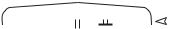
Do not lift by the fan hood. Avoid lifting fans in a way that will bend or distort fan parts. Never pass slings or timbers through the venturi of fan. Fans with special coatings or paints must be protected in handling to prevent damage.
Handling
Direct and Belt Drive Units
Lift Direct Drive unit on to the roof utilizing hooks under the horizontal supports. Evenly space the hooks using a minimum of four lifting straps. Use a spreader bar to ensure the straps do not come in contact with the unit, see Figure 1.
Figure 1
Receiving
Upon receiving the product, check to ensure all items are accounted for by referencing the delivery receipt or packing list. Inspect each crate or carton for shipping damage before accepting delivery. Alert
the carrier of any damage detected. The customer will make notation of damage (or shortage of items) on the delivery receipt and all copies of the bill of lading which is countersigned by the delivering carrier. If
damaged, immediately contact your representative. Any physical damage to the unit after acceptance is not the responsibility of the manufacturer.
Unpacking
Verify that all required parts and the correct quantity of each item have been received. If any items are
missing, report shortages to your local representative to arrange for obtaining missing parts. Sometimes it is not possible that all items for the unit be shipped together due to availability of transportation and truck space. Confirmation of shipment(s) must be limited to only items on the bill of lading.
Figure 2
Hook With
Safety Latch (Supplied by others)
 (2) Bearing Plate
Lifting Points


 (4) Drive Frame
Lifting Points
Figure 3
Screw
 Screw
Screw
2Upblast Centrifugal Roof Exhaust

When lifting a Belt Drive unit onto the roof, use either the four lifting points on the drive frame or the two lifting points on the bearing plate if present, see Figure 2 for lifting points. Access to the drive frame is accomplished by removing the screws pointed out in Figure 3. The cover can then be removed and placed on a flat surface in an area protected from strong winds.
When the Direct and/or Belt Drive unit is on the roof, move fan to desired location using lifting points and fasten securely through mounting holes in base. Shims may be necessary depending upon roofing material thickness.
The motor amperage and voltage ratings must be checked for compatibility to supply voltage prior to final electrical connection. For Direct and/or Belt Drive installations, the electrical supply should be routed through the conduit chase located between the curb cap and the bottom of the motor compartment or through the breather tube. Wiring must conform to local and national codes.
Storage
Fans are protected against damage during shipment.
If the unit cannot be installed and operated immediately, precautions need to be taken to prevent deterioration of the unit during storage. The user assumes responsibility of the fan and accessories while in storage. The manufacturer will not be responsible for damage
during storage. These suggestions are provided solely as a convenience to the user.
Indoor
The ideal environment for the storage of fans and accessories is indoors, above grade, in a low humidity atmosphere which is sealed to prevent the entry of blowing dust, rain or snow. Temperatures should be evenly maintained between 30° to 110°F (-1° to 43°C) (wide temperature swings may cause condensation and “sweating” of metal parts). All accessories must be stored indoors in a clean, dry atmosphere. Remove any accumulations of dirt, water, ice or snow and wipe dry before moving to indoor storage. To avoid “sweating” of
metal parts, allow cold parts to reach room temperature. To dry parts and packages, use a portable electric heater to get rid of any moisture buildup. Leave coverings loose to permit air circulation and to allow for periodic inspection.
The unit should be stored at least 3½ inches (89 mm) off the floor on wooden blocks covered with moisture proof paper or polyethylene sheathing. Aisles between parts and along all walls should be provided to permit air circulation and space for inspection.
Outdoor
Fans designed for outdoor applications may be stored outdoors, if absolutely necessary. Roads or aisles for portable cranes and hauling equipment are needed.
The fan should be placed on a level surface to prevent water from leaking into the fan. The fan should be elevated on an adequate number of wooden blocks so that it is above water and snow levels and has enough blocking to prevent it from settling into soft ground. Locate parts far enough apart to permit air circulation, sunlight and space for periodic inspection. To minimize water accumulation, place all fan parts on blocking supports so that rain water will run off.
Do not cover parts with plastic film or tarps as these cause condensation of moisture from the air passing through heating and cooling cycles.
Fan wheels should be blocked to prevent spinning caused by strong winds.
Inspection and Maintenance
During Storage
While in storage, inspect fans once per month. Keep a record of inspection and maintenance performed.
If moisture or dirt accumulations are found on parts, the source should be located and eliminated. At each inspection, rotate the wheel by hand ten to fifteen revolutions to distribute lubricant in motor. If paint deterioration begins, consideration should be given to touch-up or repainting. Fans with special coatings may require special techniques for touch-up or repair.
Machined parts coated with rust preventive should be restored to good condition promptly if signs of rust occur. Immediately remove the original rust preventive coating with petroleum solvent and clean with lint-free cloths. Polish any remaining rust from surface with crocus cloth or fine emery paper and oil. Do not destroy the continuity of the surfaces. Thoroughly wipe clean with Tectyl® 506 (Ashland Inc.) or the equivalent. For hard to reach internal surfaces or for occasional use, consider using Tectyl® 511M Rust Preventive, WD-40® or the equivalent.
Removing From Storage
As fans are removed from storage to be installed in their final location, they should be protected and maintained in a similar fashion until the fan equipment goes into operation.
IMPORTANT
Installation, troubleshooting and parts replacement are to be performed only by qualified personnel. Consult and follow all applicable national, state and local codes. They will supercede this document.
Upblast Centrifugal Roof Exhaust |
3 |
Dimensional Data
Direct Drive
Model Size |
Curb Cap |
Damper |
Roof/Wall |
Wall Opening |
*Approx. |
|||
Opening |
with a curb |
Weight |
||||||
|
|
|
||||||
060, 070 |
17 (432) |
8 (203) |
101⁄2 (267) |
17 (432) |
29 |
(13) |
||
080, 090, 095 |
19 (483) |
10 (254) |
121⁄2 (318) |
19 (483) |
40 |
(18) |
||
099, 101, |
19 (483) |
12 (305) |
141⁄2 (368) |
19 (483) |
67 |
(30) |
||
121, 131 |
|
|
|
|
|
|
|
|
141, 161 |
22 (559) |
16 (406) |
181⁄2 |
(470) |
22 (559) |
90 |
(41) |
|
180, 200, |
30 (762) |
18 (457) |
201⁄2 |
(521) |
30 (762) |
142 (64) |
||
200HP |
|
|
|
|
|
|
|
|
240, 240HP |
34 (864) |
24 (610) |
261⁄2 |
(673) |
N/A |
175 (79) |
||
300, 300HP |
40 (1016) |
30 (762) |
321⁄2 |
(826) |
N/A |
313 |
(142) |
|
•All dimensions are in inches (millimeters). *Approximate weight shown in lbs. (kg.) is the largest cataloged open drip proof motor.
•“Curb Cap” is the inside dimension of the curb cap
•The roof curb should be 1½ in. (38 mm) less than the curb cap to allow for roofing and flashing.
•Roof/wall opening is a square dimension.
Belt Drive
Model Size |
Curb Cap |
Shaft |
Damper |
Roof/Wall |
Wall Opening |
*Approx. |
||
Bearings |
Opening |
with a curb |
Weight |
|||||
|
|
|
||||||
099, 101, |
|
|
|
|
|
|
|
|
101HP, 121, |
19 (483) |
3⁄4 (19) |
12 (305) |
141⁄2 (368) |
19 (483) |
66 |
(30) |
|
131 |
|
|
|
|
|
|
|
|
|
|
|
|
|
|
|
|
|
141, 141HP, |
22 (559) |
3⁄4 (19) |
16 (406) |
181⁄2 (470) |
22 (559) |
87 |
(39) |
|
161, 161HP |
||||||||
|
|
|
|
|
|
|
||
|
|
|
|
|
|
|
|
|
161XP |
22 (559) |
1 (25) |
16 (406) |
181⁄2 (470) |
22 (559) |
87 |
(39) |
|
180 |
30 (762) |
3⁄4 (19) |
18 (457) |
201⁄2 (521) |
30 (762) |
126 (57) |
||
180HP |
30 (762) |
1 (25) |
18 (457) |
201⁄2 (521) |
30 (762) |
126 (57) |
||
200 |
30 (762) |
3⁄4 (19) |
18 (457) |
201⁄2 (521) |
30 (762) |
142 (64) |
||
200HP |
30 (762) |
1 (25) |
18 (457) |
201⁄2 (521) |
30 (762) |
142 (64) |
||
220, 220HP, |
|
|
|
|
|
|
|
|
240, 240HP, |
34 (864) |
1 (25) |
24 (610) |
261⁄2 (673) |
34 (864) |
175 (79) |
||
240 XP |
|
|
|
|
|
|
|
|
|
|
|
|
|
|
|
|
|
300, 300HP, |
40 (1016) |
1 (25) |
30 (762) |
32½ (826) |
40 (1016) |
313 |
(142) |
|
300XP |
||||||||
|
|
|
|
|
|
|
||
|
|
|
|
|
|
|
|
|
360, 360HP, |
46 (1168) |
11⁄4 (32) |
36 (914) |
381⁄2 (978) |
N/A |
440 |
(200) |
|
360XP |
||||||||
|
|
|
|
|
|
|
||
|
|
|
|
|
|
|
|
|
420 |
52 (1321) |
11⁄4 (32) |
42 (1067) |
441⁄2 (1130) |
N/A |
578 |
(262) |
|
480 |
58 (1473) |
11⁄2 (38) |
48 (1219) |
501⁄2 (1283) |
N/A |
675 |
(306) |
|
•All dimensions are in inches (millimeters). *Approximate weight shown in lbs. (kg.) is the largest cataloged open drip proof motor.
•“Curb Cap” is the inside dimension of the curb cap
•The roof curb should be 1½ in. (38 mm) less than the curb cap to allow for roofing and flashing.
•Roof/wall opening is a square dimension.
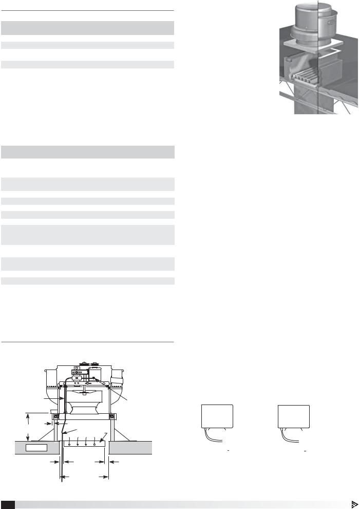
Installation
General Ventilation Installation
Screw

 Screw
Screw
Conduit |
|
Factory Wired |
|
Chase |
|
||
|
Motor to |
||
|
|
||
|
|
Disconnect |
|
3/4 in. |
|
|
|
(19 mm) |
Wiring by |
|
|
8 or 12 in. min. |
|
||
Others |
|
||
(203 or 305 mm) |
|
||
Damper |
|
||
|
|
||
Roof Deck |
|
|
|
1¼ in. |
Recommended |
1¼ in. |
|
(32 mm) |
Duct and |
(32 mm) |
|
Damper Size |
|||
|
|
||
|
Recommended |
|
|
|
Roof Opening |
|
Figure 4 - Typical Roof Mounting Installation
4Upblast Centrifugal Roof Exhaust
1.On the roof surface, cut an appropriate sized hole and follow manufacturer’s instructions on curb installation. Caulk and flash the curb to ensure a water tight seal.
2.If unit is equipped with a backdraft damper, it should be installed now.
3.Remove motor cover. Access to the motor compartment is
Figure 5 - Roof Curb Installation
accomplished by
removing the screws as shown in Figure 3, page 2.
4a. On belt drive fans, use the lifting lugs on the drive frame or bearing plate to lift and place the unit on top of roof curb. Refer to Figure 2, page 2.
4b. On direct drive fans, lift and place the unit on top of roof curb using hooks under the horizontal supports. Refer to Figure 1, page 2.
5.Secure fan to curb using a minimum of eight lag screws, metal screws or other suitable fasteners. Shims may be required depending upon curb installation and roofing material.
6.Verify power line wiring is de-energized before connecting fan motor to power source.
7.For commercial kitchen and UL Listed emergency smoke control applications, the electrical supply must enter the motor compartment through
the breather tube. For other non-flammable applications, the electrical supply can be routed through the conduit chase between the curb cap and the bottom of the motor compartment.
8.Connect power supply wiring to the motor as indicated on the motor nameplate or terminal box cover. Check the power source for compatibility with the requirements of your equipment.
9.Check fan wheel for free rotation, recenter if necessary. Check setscrew(s) for tightness.
10.Check all fasteners for tightness.
11.Mount and wire safety disconnect switch under motor cover. Wire control switches at ground level, refer to Figure 6.
MOTOR |
|
|
|
MOTOR |
|
|
|
|
||||||||||
|
|
|
|
|
|
|
SUPPLY VOLTAGE |
|
|
|
|
|
|
|
SUPPLY VOLTAGE |
|||
|
115/208-230/60/1 |
|
|
|
|
|
|
|
||||||||||
|
208-230/460/60/3 |
|||||||||||||||||
|
J-BOX |
|
J-BOX |
|||||||||||||||
|
|
|
|
|
|
|
|
L1 |
|
|
|
|
|
|
|
|
L1 |
|
|
|
|
|
|
|
|
|
|
|
|
|
|
|
|
||||
|
|
|
|
|
|
|
|
|||||||||||
|
|
|
|
|
|
|
|
L2 |
|
|
|
|
|
|
|
|
|
L2 |
|
|
|
|
|
|
|
|
|
|
|
|
|
|
|
|
L3 |
||
|
|
|
|
|
|
|
|
|
|
|
|
|
|
|
|
|
||
|
|
|
|
|
|
|
|
|
|
|
|
|
|
|
|
|
|
|
Figure 6 - Typical Wiring Diagram
12. Replace motor cover.
 Loading...