


Document 470399
Kitchen Hoods
Type I and Type II
Installation, Operation and Maintenance Manual
Please read and save these instructions for future reference. Read carefully before attempting to assemble, install, operate or maintain the product described. Protect yourself and others by observing all safety information. Failure to comply with these instructions will result in voiding of the product warranty and may result in personal injury and/or property damage.
Type I |
Type II |
General Safety Information
Only qualified personnel should install this system. Personnel should have a clear understanding of these instructions and all applicable local and national building and fire codes. Personnel should be aware of general safety precautions. SMACNA guidelines should be followed for hanging and supporting the hood. If more information is needed, contact a licensed professional engineer before moving forward.
DANGER
Always disconnect power before working on or near any electrical components in the hood. Lock and tag the disconnect switch or breaker to prevent accidental power up.
NOTE
Follow all local electrical and safety codes, as well as the National Electrical Code (NEC), and the latest edition of the National Fire Protection Agency Standard for Ventilation Control and Fire Protection
of Commercial Cooking Operations (NFPA 96). Follow the Canadian Electrical Code (CEC) and ULC-S650 if installing this product in Canada.
Kitchen Hoods • Type I and Type II |
1 |

Receiving
Upon receiving the product, check to ensure all items are accounted for by referencing the delivery receipt or packing list. Inspect each crate or carton for shipping damage before accepting delivery. Alert the carrier
of any damage detected. The customer will make a notation of damage (or shortage of items) on the
delivery receipt and all copies of the bill of lading which is countersigned by the delivering carrier. If damaged, immediately contact your Accurex Representative. Any physical damage to the unit after acceptance is not the responsibility of Accurex, LLC.
Unpacking
Verify that all required parts and the correct quantity of each item have been received. If any items are missing, report shortages to your local representative to arrange for obtaining missing parts. Sometimes it is not possible that all items for the unit be shipped together due to availability of transportation and truck space. Confirmation of shipment(s) must be limited to only items on the bill of lading. Filters are shipped on a separate skid in their original packaging. Do not
remove factory packaging or install filters until just prior to commissioning. Remove all other shipping/packing materials.
Handling
Units are to be rigged and moved by the lifting brackets provided or by the skid when a forklift is used. Location of brackets varies by model and size. Handle in such
a manner as to keep from scratching or denting. Damaged finish may reduce ability of unit to resist corrosion.
Storage
Units are protected against damage during shipment. If the unit cannot be installed and operated immediately, precautions need to be taken to prevent deterioration of the unit during storage. The user assumes responsibility of the unit and accessories while in storage. The manufacturer will not be responsible for damage during storage.
The ideal environment for storage of the hood and accessories is indoors, above grade in a clean, dry atmosphere that is sealed from the elements. While in storage, inspect equipment routinely. If any moisture, dirt or other accumulations are found on the hood or any of the parts, the source should be located and eliminated.
Removing from Storage
As equipment is removed from storage to be installed in their final location, it should be protected and maintained as outlined in the Handling section above.
2Kitchen Hoods • Type I and Type II
Table of Contents
Receiving, Unpacking, Handling and Storage . . . . . 2
Removing from Storage . . . . . . . . . . . . . . . . . . . . . . . 2 Canopy Hood Weights . . . . . . . . . . . . . . . . . . . . . . . . 3 Proximity Hood Weights . . . . . . . . . . . . . . . . . . . . . . . 4
Supply Plenum
Weights and Dimensions . . . . . . . . . . . . . . . . . . . . . . 4 Prior to Installation . . . . . . . . . . . . . . . . . . . . . . . . . . . 5
Wall or Single Island Canopy Hoods
Hood Installation Overview . . . . . . . . . . . . . . . . . . . 5-6 Filler Panel Installation . . . . . . . . . . . . . . . . . . . . . . . . 7
Clearance Reduction Methods
Top, Back, Front and End . . . . . . . . . . . . . . . . . . . . 7-8
Installing Duct Collars
Exhaust Duct Collars . . . . . . . . . . . . . . . . . . . . . . . . . 8 Integral Supply Duct Collars . . . . . . . . . . . . . . . . . . . . 8
Installing the Back Supply Plenum
Install the Supply Duct Collar . . . . . . . . . . . . . . . . . . . 9 Hang the Plenum . . . . . . . . . . . . . . . . . . . . . . . . . . . . 9 Ductwork . . . . . . . . . . . . . . . . . . . . . . . . . . . . . . . . . . . 9
Continuous Capture Plenum Hoods . . . . . . . . . . . . . 9 Installing Front/Side External Supply Plenums
Using the Uni-strut . . . . . . . . . . . . . . . . . . . . . . . . . . 10 Using Hanger Brackets and Threaded Rod . . . . . . . 10 Installing the Supply Duct Collar to the Plenum. . . . 10
Installing Backsplash Panels
Flat Backsplash Panels. . . . . . . . . . . . . . . . . . . . . . . 11 Insulated Backsplash Panels . . . . . . . . . . . . . . . . . . 11 Installing End Skirts . . . . . . . . . . . . . . . . . . . . . . . . . 12
Electrical Connections
Hood Lights / Fan and/or Thermal (Tempering) Switches / Keypads or Touchscreens (Vari-Flow). . . 12
Installing Enclosure Panels . . . . . . . . . . . . . . . . . . . 13 Double Island Canopy Style Hoods
Installing U-Channel Strips . . . . . . . . . . . . . . . . . . . . 13
Proximity (Backshelf) Hoods . . . . . . . . . . . . . . . . . . 14 Plate Shelf with Duct Enclosure Installation . . . . . . . 14
Balancing the Kitchen Exhaust System . . . . . . . . . 15 Testing Hood Air Volume - Procedures
with Baffle Filters (GH Series) . . . . . . . . . . . . . . 16-17 with High Velocity Cartridge Filters (GK Series) 18-19 with High Efficiency Filters (GX and GG Series) 20-21 Perforated Face Supply . . . . . . . . . . . . . . . . . . . . . . 22 Short Circuit Hoods . . . . . . . . . . . . . . . . . . . . . . . . . 23
Exhaust Air Balancing Baffles . . . . . . . . . . . . . . . . . 24 Wiring Diagrams
Amerex® Wiring Plan View. . . . . . . . . . . . . . . . . . . . 25 Ansul® Wiring Plan View . . . . . . . . . . . . . . . . . . . . . 26 Wiring Plan View for Kitchen Systems . . . . . . . . . . . 27 Wiring for Switch Panels and Circuit Diagrams . . . . 28
Maintenance
Daily, Weekly, Periodic . . . . . . . . . . . . . . . . . . . . . . . 29 Condensate Hood Baffle and Air Diffusers. . . . . . . . 29 Grease Grabber™ Filters Installation & Cleaning 29-30 Filter Washing Frequency Guide. . . . . . . . . . . . . . . . 31 Troubleshooting. . . . . . . . . . . . . . . . . . . . . . . . . . 32-33 Replacement Parts . . . . . . . . . . . . . . . . . . . . . . . . . . 34 Maintenance Log. . . . . . . . . . . . . . . . . . . . . . . . . . . . 35 Our Commitment. . . . . . . . . . . . . . . . . . . . . . . . . . . . 36

Canopy Hood Weights
|
|
|
|
Hood Depth (Multiply by Length) for Hood Weight* |
|
|
|
|||||
Hood Model |
|
|
|
|
|
|
|
|
|
|
|
|
2 ft |
2.5 ft |
3 ft |
3.5 ft |
4 ft |
4.5 ft |
5 ft |
5.5 ft |
6 ft |
6.5 ft |
7 ft |
7.5 ft |
|
|
.609 m |
.762 m |
.914 m |
1.067 m |
1.219 m |
1.372 m |
1.524 m |
1.676 m |
1.829 m |
1.981 m |
2.134 m |
2.286 m |
|
|
|
|
|
|
|
|
|
|
|
|
|
XB, XK, |
|
|
30 lbs/ft |
32 lbs/ft |
35 lbs/ft |
38 lbs/ft |
40 lbs/ft |
|
|
|
|
|
XX, XTEW |
|
|
44.64 kg/m |
47.62 kg/m |
52.09 kg/m |
56.55 kg/m |
59.53 kg/m |
|
|
|
|
|
|
|
|
|
|
|
|
|
|
|
|
|
|
XB, XK, |
|
|
36 lbs/ft |
38 lbs/ft |
41 lbs/ft |
44 lbs/ft |
46 lbs/ft |
|
|
|
|
|
XX, XTDW |
|
|
53.57 kg/m |
56.55 kg/m |
61.01 kg/m |
65.48 kg/m |
68.46 kg/m |
|
|
|
|
|
|
|
|
|
|
|
|
|
|
|
|
|
|
XB, XK, XXFW |
|
|
|
40 lbs/ft |
44 lbs/ft |
48 lbs/ft |
52 lbs/ft |
|
|
|
|
|
|
|
|
59.53 kg/m |
65.48 kg/m |
71.43 kg/m |
77.38 kg/m |
|
|
|
|
|
|
|
|
|
|
|
|
|
|
|
||||
|
|
|
|
|
|
|
|
|
|
|
|
|
XB, XK, XXCW |
|
|
|
48 lbs/ft |
51 lbs/ft |
54 lbs/ft |
57 lbs/ft |
|
|
|
|
|
|
|
|
71.43 kg/m |
75.90 kg/m |
80.36 kg/m |
84.83 kg/m |
|
|
|
|
|
|
|
|
|
|
|
|
|
|
|
||||
|
|
|
|
|
|
|
|
|
|
|
|
|
XB, XK, XXSW |
|
|
|
44 lbs/ft |
48 lbs/ft |
52 lbs/ft |
56 lbs/ft |
|
|
|
|
|
|
|
|
65.48 kg/m |
71.43 kg/m |
77.38 kg/m |
83.34 kg/m |
|
|
|
|
|
|
|
|
|
|
|
|
|
|
|
||||
|
|
|
|
|
|
|
|
|
|
|
|
|
XGEW |
|
|
39 lbs/ft |
41 lbs/ft |
44 lbs/ft |
47 lbs/ft |
49 lbs/ft |
|
|
|
|
|
|
|
58.04 kg/m |
61.01 kg/m |
65.48 kg/m |
69.94 kg/m |
72.92 kg/m |
|
|
|
|
|
|
|
|
|
|
|
|
|
|
|||||
|
|
|
|
|
|
|
|
|
|
|
|
|
XGDW |
|
|
45 lbs/ft |
47 lbs/ft |
50 lbs/ft |
53 lbs/ft |
55 lbs/ft |
|
|
|
|
|
|
|
66.97 kg/m |
69.94 kg/m |
74.41 kg/m |
78.87 kg/m |
81.85 kg/m |
|
|
|
|
|
|
|
|
|
|
|
|
|
|
|||||
|
|
|
|
|
|
|
|
|
|
|
|
|
XGFW |
|
|
|
49 lbs/ft |
53 lbs/ft |
57 lbs/ft |
61 lbs/ft |
|
|
|
|
|
|
|
|
72.92 kg/m |
78.87 kg/m |
84.83 kg/m |
90.78 kg/m |
|
|
|
|
|
|
|
|
|
|
|
|
|
|
|
||||
|
|
|
|
|
|
|
|
|
|
|
|
|
XGCW |
|
|
|
57 lbs/ft |
60 lb/ft |
63 lbs/ft |
66 lbs/ft |
|
|
|
|
|
|
|
|
84.83 kg/m |
89.29 kg/m |
93.75 kg/m |
98.22 kg/m |
|
|
|
|
|
|
|
|
|
|
|
|
|
|
|
||||
|
|
|
|
|
|
|
|
|
|
|
|
|
XGSW |
|
|
|
53 lbs/ft |
57 lbs/ft |
61 lbs/ft |
65 lbs/ft |
|
|
|
|
|
|
|
|
78.87 kg/m |
84.83 kg/m |
90.78 kg/m |
96.73 kg/m |
|
|
|
|
|
|
|
|
|
|
|
|
|
|
|
||||
|
|
|
|
|
|
|
|
|
|
|
|
|
XB, XK, XXEV |
|
|
|
|
52 lbs/ft |
54 lbs/ft |
56 lbs/ft |
58 lbs/ft |
61 lbs/ft |
63 lbs/ft |
|
|
|
|
|
|
77.38 kg/m |
80.36 kg/m |
83.34 kg/m |
86.31 kg/m |
90.78 kg/m |
93.75 kg/m |
|
|
|
|
|
|
|
|
|
|
||||||
|
|
|
|
|
|
|
|
|
|
|
|
|
XB, XK, XXFV |
|
|
|
|
61 lbs/ft |
66 lbs/ft |
68 lbs/ft |
72 lbs/ft |
75 lbs/ft |
79 lbs/ft |
|
|
|
|
|
|
90.78 kg/m |
98.22 kg/m |
101.20 kg/m |
107.15 kg/m |
111.61 kg/m |
117.56 kg/m |
|
|
|
|
|
|
|
|
|
|
||||||
|
|
|
|
|
|
|
|
|
|
|
|
|
XB, XK, XXCV |
|
|
|
|
|
|
|
|
81 lbs/ft |
84 lbs/ft |
87 lbs/ft |
90 lbs/ft |
|
|
|
|
|
|
|
|
120.54 kg/m |
125.01 kg/m |
129.47 kg/m |
133.93 kg/m |
|
|
|
|
|
|
|
|
|
|
||||
|
|
|
|
|
|
|
|
|
|
|
|
|
XB, XK, XXSV |
|
|
|
|
|
66 lbs/ft |
69 lbs/ft |
72 lbs/ft |
76 lbs/ft |
79 lbs/ft |
|
|
|
|
|
|
|
98.22 kg/m |
102.68 kg/m |
107.15 kg/m |
113.10 kg/m |
117.56 kg/m |
|
|
|
|
|
|
|
|
|
|
|
|||||
|
|
|
|
|
|
|
|
|
|
|
|
|
XO/XD1 |
20 lbs/ft |
24 lbs/ft |
28 lbs/ft |
32 lbs/ft |
36 lbs/ft |
40 lbs/ft |
44 lbs/ft |
48 lbs/ft |
52 lbs/ft |
|
|
|
29.76 kg/m |
35.72 kg/m |
41.67 kg/m |
47.62 kg/m |
53.57 kg/m |
59.52 kg/m |
65.48 kg/m |
71.43 kg/m |
77.38 kg/m |
|
|
|
|
|
|
|
|
|||||||||
|
|
|
|
|
|
|
|
|
|
|
|
|
XD2 |
|
|
43 lbs/ft |
48 lbs/ft |
53 lbs/ft |
58 lbs/ft |
63 lbs/ft |
68 lbs/ft |
73 lbs/ft |
|
|
|
|
|
63.99 kg/m |
71.43 kg/m |
78.87 kg/m |
86.31 kg/m |
93.75 kg/m |
101.20 kg/m |
108.64 kg/m |
|
|
|
|
|
|
|
|
|
|
|||||||
|
|
|
|
|
|
|
|
|
|
|
|
|
XD3 |
|
|
58 lbs/ft |
64 lbs/ft |
70 lbs/ft |
76 lbs/ft |
82 lbs/ft |
88 lbs/ft |
94 lbs/ft |
|
|
|
|
|
86.31 kg/m |
95.24 kg/m |
104.17 kg/m |
113.10 kg/m |
122.03 kg/m |
130.96 kg/m |
139.89 kg/m |
|
|
|
|
|
|
|
|
|
|
|||||||
|
|
|
|
|
|
|
|
|
|
|
|
|
*Hood weight calculations are based on standard selection. Hood height, accessories and material gauge affect overall hood weight.
Kitchen Hoods • Type I and Type II |
3 |

Proximity Hood Weights
Hood weight is determined using a simple formula. Select the figures provided in columns A and B (see tables) from the three respective categories—Hood Width, Filter Type and Hood Height—based on the hood received. Total
the three numbers in column A and the three numbers in column B. Place the sum for column A and the sum for column B in the Hood Weight equation where shown and solve for the total Hood Weight.
IMPERIAL |
|
|
A |
|
|
B |
|
|
|
||
Category 1: |
|
|
Hood Width (in.) |
|
|
|
|||||
|
23 - 25 |
|
|
1.3 |
|
|
28 |
|
|
|
|
|
26 - 28 |
|
|
1.35 |
|
|
30 |
|
|
|
|
|
29 - 32 |
|
|
1.4 |
|
|
31.5 |
|
|
|
|
|
33 - 36 |
|
|
1.45 |
|
|
33.5 |
|
|
|
|
Category 2: |
|
|
|
Filter Type |
|
|
|
||||
|
Baffle |
|
|
0.3 |
|
|
0 |
|
|
|
|
Grease-X-Tractor™ |
|
0.4 |
|
|
0 |
|
|
|
|||
|
or Cartridge |
|
|
|
|
|
|
|
|||
|
|
|
|
|
|
|
|
|
|
|
|
Grease Grabber™ |
|
1 |
|
|
|
0 |
|
|
|
||
Category 3: |
|
|
Hood Height (in.) |
|
|
|
|||||
|
24 - 27 |
|
|
0 |
|
|
|
0 |
|
|
|
|
28 - 33 |
|
|
0.08 |
|
|
5 |
|
|
|
|
|
34 - 38 |
|
|
0.16 |
|
|
10 |
|
|
|
|
|
39 - 42 |
|
|
0.24 |
|
|
15 |
|
|
|
|
|
|
|
|
|
|
|
|
|
|
|
|
Example: |
|
|
|
|
|
|
|
A |
|
B |
|
|
|
|
|
|
|
|
|||||
Category 1: Hood Width |
|
|
23 - 25 |
1.3 |
|
28 |
|||||
|
|
|
|
|
|
|
|
|
|||
Category 2: Filter Type |
|
|
|
|
Baffle |
0.3 |
|
0 |
|||
|
|
|
|
|
|
|
|||||
Category 3: Hood Height |
|
|
24 - 27 |
0 |
|
0 |
|||||
|
|
|
|
|
|
Total: |
1.6 |
|
28 |
||
Hood Weight Equation (lb.) |
|
|
|
|
|||||||
A |
x |
Length (in.) |
+ |
B |
= |
Weight (lb.) |
|||||
1.6 |
x |
48 |
+ |
28 |
= |
104.8 lb. |
METRIC |
|
A |
|
|
B |
|
|
|
||
Category 1: |
|
|
Hood Width (cm) |
|
|
|
||||
58.42 - 63.50 |
|
0.232 |
|
12.68 |
|
|
|
|||
66.04 - 71.12 |
|
0.241 |
|
13.59 |
|
|
|
|||
73.66 - 81.28 |
|
0.250 |
|
14.27 |
|
|
|
|||
83.82 - 91.44 |
|
0.259 |
|
15.18 |
|
|
|
|||
Category 2: |
|
|
|
Filter Type |
|
|
|
|||
Baffle |
|
0.054 |
|
0 |
|
|
|
|||
Grease-X-Tractor™ |
|
0.071 |
|
0 |
|
|
|
|||
or Cartridge |
|
|
|
|
|
|||||
|
|
|
|
|
|
|
|
|
||
Grease Grabber™ |
|
0.178 |
|
0 |
|
|
|
|||
Category 3: |
|
|
Hood Height (cm) |
|
|
|
||||
60.96 - 68.58 |
|
0.000 |
|
0 |
|
|
|
|||
71.12 - 83.82 |
|
0.014 |
|
2.27 |
|
|
|
|||
86.36 - 96.52 |
|
0.029 |
|
4.53 |
|
|
|
|||
99.06 - 106.68 |
|
0.043 |
|
6.80 |
|
|
|
|||
|
|
|
|
|
|
|
|
|
|
|
Example: |
|
|
|
|
|
|
|
A |
|
B |
|
|
|
|
|
|
|
||||
Category 1: Hood Width |
|
|
58.42 - 63.50 |
0.232 |
|
12.68 |
||||
|
|
|
|
|
|
|
|
|
||
Category 2: Filter Type |
|
|
|
|
Baffle |
0.054 |
|
0 |
||
|
|
|
|
|
|
|||||
Category 3: Hood Height |
|
60.96 - 68.58 |
0 |
|
0 |
|||||
|
|
|
|
|
Total: |
1.6 |
|
28 |
||
Hood Weight Equation (kg.) |
|
|
|
|
||||||
A |
x Length (cm.) |
+ |
B |
= |
Weight (kg.) |
|||||
0.286 |
x |
121.92 |
+ |
12.68 |
= |
47.5 kg. |
Supply Plenum - Weights and Dimensions
|
|
External Supply |
|
|
Weight |
|
|
|
|
|
Width |
|
|
|
Height |
|
Length per section |
|||||||||||||||
|
|
|
Plenum Type |
|
|
lbs/ft |
|
kg/m |
|
in. |
|
|
mm |
|
|
|
in. |
|
mm |
|
|
ft. |
|
|
m |
|||||||
|
|
|
|
|
|
|
|
Refer to Air Curtain |
Refer Air Curtain |
|
|
|
|
|
|
|
|
|
|
|
|
|
|
|
|
|
|
|
||||
Air Curtain Supply (ASP) |
|
Supply Plenum |
Supply Plenum |
10 to 24 |
|
254.0 to 609.6 |
|
10 |
254.0 |
|
3 to 16 |
|
.91 to 4.88 |
|||||||||||||||||||
|
|
|
|
|
|
|
|
Weight Table |
Weight Table |
|
|
|
|
|
|
|
|
|
|
|
|
|
|
|
|
|
|
|
||||
|
|
|
|
|
|
|
|
|
|
|
|
|
|
|
|
|
|
|
|
|
|
|
|
|
|
|
|
|
||||
Split Air Curtain Supply |
15.5 |
|
23.07 |
|
|
24 |
|
609.6 |
|
|
10 |
254.0 |
|
3 to 16 |
|
.91 to 4.88 |
||||||||||||||||
(Split ASP) |
|
|
|
|
|
|
|
|
|
|||||||||||||||||||||||
|
|
|
|
|
|
|
|
|
|
|
|
|
|
|
|
|
|
|
|
|
|
|
|
|
|
|
||||||
|
|
|
|
|
|
|
|
|
|
|
|
|
|
|
|
|
|
|
|
|
|
|
|
|
|
|
|
|
||||
Back Supply (BSP) |
|
35.0 |
|
52.09 |
|
|
6 |
|
152.4 |
|
|
Variable |
|
Variable |
|
3 to 16 |
|
.91 to 4.88 |
||||||||||||||
|
|
|
|
|
|
|
|
|
|
|
|
|
|
|
|
|
|
|
|
|
|
|
|
|
|
|
|
|||||
Horizontal Supply (HSP) |
14.0 |
|
20.83 |
|
|
12 |
|
304.8 |
|
|
18 |
457.2 |
|
3 to 16 |
|
.91 to 4.88 |
||||||||||||||||
|
|
|
|
|
|
|
|
|
|
|
|
|
|
|
|
|
|
|
|
|
|
|
|
|
|
|
|
|||||
Variable Supply (VSP) |
16.0 |
|
23.81 |
|
|
12 |
|
304.8 |
|
|
18 |
457.2 |
|
3 to 16 |
|
.91 to 4.88 |
||||||||||||||||
|
|
|
|
|
|
|
|
|
|
|
|
|
|
|
|
|
|
|
|
|
|
|
|
|
|
|
|
|
|
|
||
|
|
|
|
|
|
|
|
|
|
|
|
|
|
|
|
|
|
|
|
|
|
|
|
|
|
|
|
|||||
Weight |
|
|
|
|
|
|
|
|
Air Curtain Supply Plenum Width (inches) |
|
|
|
|
|
|
|
|
|
|
|
||||||||||||
|
|
|
|
|
|
|
|
|
|
|
|
|
|
|
|
|
|
|
|
|
|
|
|
|
|
|
|
|
||||
10 |
|
11 |
|
12 |
13 |
14 |
|
15 |
|
16 |
|
17 |
|
|
18 |
19 |
|
20 |
|
21 |
22 |
|
23 |
|
24 |
|||||||
|
|
|
|
|
|
|
|
|
|
|
|
|
|
|
||||||||||||||||||
|
|
|
|
|
|
|
|
|
|
|
|
|
|
|
|
|
|
|
|
|
|
|
|
|
|
|
|
|||||
|
lbs/ft |
|
8.3 |
|
8.6 |
|
8.9 |
9.2 |
9.5 |
|
9.8 |
|
10.1 |
|
10.4 |
|
10.7 |
11.1 |
|
11.3 |
|
11.6 |
11.9 |
|
12.2 |
|
12.5 |
|||||
|
|
|
|
|
|
|
|
|
|
|
|
|
|
|
|
|
|
|
|
|
|
|
|
|
|
|
||||||
|
kg/m |
|
12.35 |
|
12.80 |
|
13.24 |
13.69 |
14.14 |
|
14.58 |
|
15.03 |
|
15.48 |
|
15.92 |
16.52 |
|
16.82 |
|
17.26 |
17.71 |
|
18.16 |
18.60 |
||||||
|
|
|
|
|
|
|
|
|
|
|
|
|
|
|
|
|
|
|
|
|
|
|
|
|
|
|
|
|
|
|
||
|
|
|
|
|
|
|
|
|
|
|
|
|
|
|
|
|
|
|
|
|
|
|
|
|
|
|
|
|
|
|
|
|
4 |
|
Kitchen Hoods • Type I and Type II |
|
|
|
|
|
|
|
|
|
|
|
|
|
|
|
|
|
|
|
|
|
|
|
|||||||
Prior to Installation
Prior to installation, check with the Authorities Having Jurisdiction (AHJ) on clearance requirements to structures surrounding the hood and other equipment. Verify there is enough space to safely lift hood up into its operating position and enough clearance around the hood for components like fire system connections, hood lights, hood control components, etc. Consider access for servicing the equipment and the different components when locating the hood.
If the hood is a grease hood (Type I), the UL label located on the end panel on the inside of the hood will provide pertinent information regarding the hood installation. Information includes:
•Allowable cooking surface temperatures of the cooking equipment
•Front and side overhang/underhang requirements
•Minimum exhaust (and possibly supply) airflow requirements
•Hood lighting load information and restrictions
•Filter information
•Fire damper fusible link replacement information, if applicable
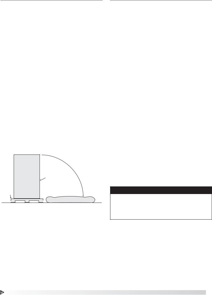
With the hood still inside its packing crate, position the unit beneath its installation location. Carefully remove the packing crate and place some protective material on the floor next to the crate to avoid damaging the hood as it is tipped on its side. Tip the hood carefully onto the protective material.
Pallet |
Bottom of Hood
Protective Material
Wall or Single Island Canopy Hoods
Hood Installation Overview
1.If the hood is provided with filler panels, shipped loose, install them now. See page 7, Filler Panel Installation. Filler panels may be integral to the hood, which requires no additional installation.
2.If the hood is equipped with Clearance Reduction Methods, refer to pages 7 and 8 for special considerations with hanging the hood.
3.If the hood is provided with hood/duct sensors or thermostats, install them now. See the Installation and Operations guide provided with the control panel.
4.If the hood was provided with either exhaust collars or supply collars that have shipped loose, it is recommended that the exhaust and supply openings are cut and collars are attached now, prior to hanging the hood. See page 8, Installing Duct Collars.
5If the hood is provided with a back supply plenum (BSP) install it now. See page 9, Installing the Back Supply Plenum.
6.If possible, connect (weld) exhaust duct to the hood while on the floor, unless it prohibits the hood from being raised into place. For information on ductwork, see page 9, Ductwork.
7.At this point, drill holes in the building structural support system or utilize uni-strut to match up with the hanger bracket holes. Then slowly and evenly raise the hood into position and insert 1/2-inch (12.7 mm) diameter threaded rod (provided by others) between the hanger brackets and structure.
For Type I hoods, the hood hanging height requirements are given on the UL label. Typical canopy hood hanging height will be 80 inches (198.12 cm) off the finished floor.
NOTE
If the hood is supplied with ceiling enclosures, the height of the enclosures will typically be the distance from the ceiling to the top of the hood. Use this dimension to find the hood’s hanging height off of the floor.
For questions regarding the supporting structure and its integrity, either the contractor or structural engineer needs to be consulted.
Kitchen Hoods • Type I and Type II |
5 |

Wall or Single Island Canopy Hoods - continued
NOTE
All hanger brackets MUST be used and the hood must be properly supported while lifting to prevent damage or distortion to the hood.
NOTE
The hood MUST be hung evenly. If hung unevenly, this may cause grease drainage problems. Provide additional support if necessary so that the hood doesn’t move in a manner that is acceptable with the Authorities Having Jurisdiction (AHJ).
WARNING
When mounting the hood or any components against the hood, never puncture or drill into the canopy. This will void the hood listing and warranty.
8.If the hood was provided in sections with the continuous capture option, once each hood section is hung, install this option now. See page 9, Continuous Capture Plenum Hoods.
9.If the hood was provided with any front or side external supply plenums (other than the back supply plenum), install these now. See page 10, Installing Front/Side External Supply Plenums.
10.Install the remainder of both the exhaust and supply ductwork. For further guidelines see page 9, Ductwork.
11.If the hood is provided with any backsplash/ sidesplash panels, install them now. See page 11, Installing Backsplash Panels.
12.If the hood is provided with any end skirts, install them now. See page 12, Installing End Skirts.
13.If the hood is a Type I hood, it will require a fire suppression system. Once the Type I hood(s) and ductwork are fully installed, appliances are in place and walls are complete, the fire system should be completed. If the hood is provided with a full factory-coordinated fire suppression system
installation, the certified fire system installer should be contacted at this time to complete the final hookups, testing and system certification based upon manufacturer’s specification and local fire codes. If the hood is not provided with either prepiping only or no fire suppression system, it is the responsibility of a certified fire system installer
to install, test and certify the system based upon manufacturer’s specification and local fire codes.
14.If the hood is provided with a control package, these will need to be installed and wired by the jobsite electrician. This typically includes wiring the hood temperature sensors, hood lights and wiring the fire suppression micro-switches. For general hood electrical connections, see page 12, Electrical Connections. If applicable, see the Installation
and Operations guide provided with the control package.
6Kitchen Hoods • Type I and Type II
15.If the hood is provided with enclosure panels, install them now. See page 13, Installing Enclosure Panels.
16.Install the rest of the hood accessories provided. This may include grease filters or condensate hood baffles, grease cups, light bulbs (provided by others unless LED tube style), light globes, and trim strips.
It is recommended that the protective plastic sheeting remain on the hood until fully installed to better protect the product from scratching and marking. Once removed, use stainless steel polish, such as BlueAway or equivalent, to clean the hood and/or remove marks or discoloration. Be sure to wipe with the grain and not against it.
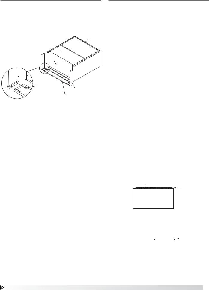
Filler Panel Installation
1.Uncrate the hood and lay it on the floor with protective material between the hood and the floor.
2.Bolt the filler panels together with 5/16 in. bolts provided in the hardware package.
3.Position the filler panels to the hood back, and tackweld them into place.
 TACK-WELDED TO HOOD BACK
5/16 IN. X 3/4 IN. BOLTS WITH WASHERS & NUTS
HOOD
 HOOD
HOOD
HOOD
RIGHT FILLER PANEL
BOTTOM FILLER PANEL
4.To allow for ease of cleaning, caulk the external seams with NSF Approved silicone caulk (GE SCS1009, or its equivalent). The caulk is not provided.
Clearance Reduction Methods
Clearance reduction methods have been evaluated and tested and are listed by UL (Underwriters Laboratory). The method of test was derived from the UL 710 test standard.
The hood may be installed with zero clearance to combustible materials if constructed in the following manner.
1.One inch (2.54 cm) thick layer of insulation of Owens Corning® Type 475, Johns Manville Type 475, IIG® MinWool-1200® Flexible Batt, or Knauf Insulation Type EI 475.
2.Insulation must be held securely in place. Pins that are welded or secured with an adhesive may be used.
3.A backsplash panel must be attached to the wall (insulated or uninsulated).
To comply with the UL Listing, the cooking appliances must be as follows:
•Maximum surface temperature is 700°F (371°C)
•Appliances are located at least 3 in. (7.62 cm) from the rear wall
•Appliances are at least 40 in. (101.6 cm) below the bottom front edge of the hood
The hood may be installed with 3 in. (7.62 cm) clearance to limited combustible materials per NFPA 96 if constructed in one of the following methods:
•3 in. (7.62 cm) rear uninsulated stand-off
•3 in. (7.62 cm) top enclosure panel system
•3 in. (7.62 cm) end uninsulated stand-off
Top Clearance Reduction Options
One inch (2.54 cm) layer of insulation installed on top of the hood (optional) meets zero inch requirements for
clearance to combustible surfaces as outlined under the clearance reductions methods.
Three inches (7.62 cm) uninsulated airspace installed on top of hood (optional) meets NFPA 96 requirements for clearance to limited combustible surfaces.
|
|
|
|
|
|
|
|
|
|
|
|
|
|
|
|
|
|
|
|
|
|
|
|
|
|
|
|
|
Kitchen Hoods • Type I and Type II |
7 |
||||
Back and Front Clearance Reduction Options
One inch (2.54 cm) layer of insulation in 3 in. (7.62 cm) back stand-off meets zero inch requirements for clearance to combustible surfaces as outlined under the clearance reduction methods.
Three inches (7.62 cm) uninsulated back stand-off meets NFPA 96 requirements for clearance to limited combustible surfaces.
One inch (2.54 cm) layer of insulation factory-installed on the front of the hood (optional) meets zero inch requirements for clearance to combustible surfaces.
End Clearance Reduction Options
One inch (2.54 cm) layer of insulation factory-installed on the end of the hood (optional) meets zero inch requirements for clearance to combustible surfaces under the clearance reduction methods.
Three inches (7.62 cm) uninsulated airspace installed on end of hood (optional). Meets NFPA 96 requirements for clearance to limited combustible surfaces.
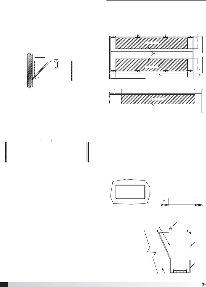
Installing Duct Collars
Exhaust Duct Collars
1.The exhaust duct connection needs to be located within 48 in. (121.92 cm) from the center of the hood length to the center of the duct connection and within shaded area as shown.
Top View of the Hood
|
Hanger Bracket |
|
3 in. |
|
Exhaust Plenum |
|
14 in. |
|
Duct cut out area |
|
Hood |
|
|
|
Width |
|
|
|
16 in. |
|
Supply Plenum |
|
|
8 in. |
Front of hood |
8 in. |
3 in. |
|
|
Hood Length 
Back View of the Hood
|
|
|
8 in. |
|
|
|
8 in. |
1 in. |
|
|
Hood Top |
||||
12 in. |
Exhaust Plenum |
|
Duct cut out area |
2.The exhaust duct connection is to be a continuous liquid-tight weld. Weld with a non-ferrous filler wire, such as silicon bronze or stainless steel filler wire.
Protect all stainless steel areas from weld splatter.
Integral Supply Duct Collars
1.The supply duct connection needs to be located within the shaded Supply Plenum area as in the drawing above.
2.The supply duct connection is tack-welded at 1 to 2 inch (2.54 to 5.08 cm) intervals or sheet metal screws at 3 to 6 in. (7.62 to 15.24 cm) spacing to the hood.
Supply duct connection to be tack welded with 1 to 2 inch tack or
sheet metal screws at 3 to 6 inch Supply Duct  spacing to hood.
Connection
3. For hoods that are insulated, the edges of the insulation must be taped after the hole is cut. (The
insulation tape |
Internal Supply |
Supply Fire Damper |
is provided by |
|
|
Chamber |
|
|
others). |
|
|
4. On combination |
|
|
hoods, make |
|
Hood |
certain the |
|
|
fire damper |
|
|
is located |
|
|
over the |
|
Insulated |
internal supply |
|
Supply |
|
Plenum |
|
chamber. |
|
|
|
|
Exhaust Capture |
8 Kitchen Hoods • Type I and Type II
Installing the Back Supply Plenum
Install the Supply Duct Collar
1. Find the center of the back supply plenum.
2. If the back supply plenum is to have |
L (MODULE LENGTH) |
|
one opening, cut the opening such |
||
L/2 |
||
that it is centered at L /2 from the |
||
L/2 |
||
|
||
plenum end. (Fig. 1) |
|
3.If the back supply plenum is to have two openings, cut openings such that they are centered at L /4 from each end of the plenum.
(Fig. 2) |
|
Fig. 1 |
4. Place the duct |
L/4 |
L (MODULE LENGTH) |
collar(s) over the |
|
|
|
L/2 |
|
opening(s), fastening |
|
|
|
|
|
with screws or |
|
L/4 |
tack-welds every |
|
|
4 to 6 in. (10.16 to |
|
|
15.24 cm). (Fig. 3) |
|
|
Hang the Plenum |
Fig. 2 |
5. Hang the back |
|
supply plenum |
|
from the ceiling. |
|
The back supply plenum |
|
needs to be mounted 31.25 in. |
|
(79.375 cm) above the finished |
|
floor. This is measured from the |
|
lowest rear edge of the back |
|
supply plenum to the finished |
|
floor. (Fig. 4) |
Fig. 3 |
Hang using threaded rod
placed through the hanger brackets.
Ductwork
Exhaust - As specified in NFPA 96, Ch. 7.5 (latest edition), exhaust duct systems must be constructed in the following manner:
Materials: Ducts shall be constructed of and supported by carbon steel not less than 1.37 mm (0.054 in.) (No. 16 MSG) in thickness, or stainless steel not less than 1.09 mm (0.043 in.) (No. 18 MSG) in thickness.
Installation: All seams, joints, penetrations, and duct to hood collar connections shall have a liquid-tight external weld. If you have an automatic fire damper, please refer to that manual for installation instructions now.
Supply - Supply ductwork (where applicable) should be connected to the hood in a manner approved by the local code authorities.
NOTE
For hoods with fire dampers in the exhaust and supply duct collars, an access panel for cleaning and inspection shall be provided in the duct. This panel shall be as close to the hood as possible but should not exceed 18 in. (45.72 cm).
For proper installation of duct collars when they are shipped unattached, see page 8.
Continuous Capture Plenum Hoods
1. Remove the support angles provided for support during shipping on the open
end panels. Install and level both hoods. 

REMOVE
SUPPORT
ANGLES ON
THE OPEN
END PANEL
FRONT HOOD
FASTENERS HOLDING THE
BACKSUPPLY TO THE WALL
31.25 INCH
CRITICAL
DIMENSION
Fig. 4
6.Fasten the back supply to the wall, going through the lower back supply wall.
•These fasteners are to help maintain the location of the back supply, and are not intended to hold the weight of the back supply unit.
•The fasteners should not interfere with the removable air diffusers.
FRONT
HOOD
2.After leveling, secure the hoods together by tackwelding and/or bolting the angles that are located at the top of the hoods along its width (Fig. 5).
3.Next, fasten the hoods together at its inside plenum profile using u-clips and bolts (Fig. 6). Caulk this joint with NSF Approved silicone caulk (GE SCS1009 or its equivalent). The caulk is not provided.
1. REM
2. RAIS
AND
|
|
|
|
|
|
|
|
|
3. FAST |
|
|
|
|
|
|
|
|
|
|
4. FAST |
|
|
|
|
|
|
|
|
|
|
& CA |
|
|
|
Fig. 5 |
|
5. CAU |
||||||
|
|
|
|
|
||||||
|
SUPPORT ANGLES |
BOLT OR WELD |
||||||||
|
|
|
|
|
|
|
|
|
|
|
|
|
|
|
|
|
|
|
|
|
|
|
|
|
|
|
|
|
|
|
|
|
|
HOOD TOP |
|
|
|
|
|
|
|||
|
|
|
|
|
|
|
||||
|
HOOD END |
|
|
|
|
|
|
|||
|
|
|
|
|
|
|
|
|
|
|
|
Fig. 6 |
|
HOOD |
CAULK |
|
BOLT |
ACORN |
NUT |
|
|
U-CLIP |
Kitchen Hoods • Type I and Type II |
9 |

Installing Front/Side External Supply Plenums
Using the Uni-strut
THREADED ROD
SUPPLIED BY OTHERS
UNI-STRUT (U-CHANNEL)
SUPPLIED BY OTHERS
EXTERNAL
SUPPLY
PLENUM
END VIEW
HOOD
The uni-strut (supplied by others) supporting the hood may be cantilevered over the end of the hood. Utilizing the external supply plenum’s hanger brackets, securely fasten to the uni-strut.
THREADED
ROD
 UNI-STRUT


 (U-CHANNEL)


Air Curtain Supply (ASP)
Horizontal Supply Plenum (HSP)
Variable Supply Plenum (VSP)
Mounted with uni-strut and threaded rod
When using the uni-strut (supplied by others), it must be bolted to the hood and external supply plenum hanger brackets.
NOTE
The uni-strut needs to be the full length of the hood and the external supply plenum.
Using Hanger Brackets and Threaded Rod
Air Curtain |
Horizontal Supply Plenum (HSP) |
Supply Plenum (ASP) |
Variable Supply Plenum (VSP) |
10 Kitchen Hoods • Type I and Type II
1.Insert 1/2 in. (12.7 mm) diameter threaded rod (by others) into hanger brackets on the external supply plenum top. Raise and hang the external supply plenum from adequate roof or ceiling supports.
NOTE
Ensure the external supply plenum is installed flush with the hood front and is plumb and level by
adjusting the threaded rod(s). There should be no gap between the bottom of the external supply plenum and the hood after installation and adjustments are completed.
2.The external supply plenum should be resting lightly against the hood. The hood is only used to position the plenum; it is not intended to support the plenum. All hanger brackets on the external supply plenum must be used and the plenum must be
properly supported while lifting to prevent damage or distortion. The external supply plenum must be level to operate properly.
NOTE
After hanging, secure the external supply plenum to the hood (or to another external supply plenum) using the supplied turnbuckle(s). Use caution tensioning the turnbuckle. Too much tension may cause the bottom of the external supply plenum to pull away from
the hood or cause the face of the hood to become deformed.
TURNBUCKLE
HOOD HANGER
 BRACKET
EXTERNAL
SUPPLY PLENUM
HANGER BRACKET
HOOD
EXTERNAL
SUPPLY
PLENUM
3.It is recommended that caulk be applied at the mating seams and surfaces of the external supply plenum, the hood, and the wall. If the external supply plenum is next to a wall, you will need to caulk around the surface next to the wall. Caulk the joints with NSF Approved silicone caulk (GE SCS1009, or its equivalent). The caulk is not provided.
Installing the Supply Duct Collar to the Plenum
Place the duct collar(s) over the opening, fastening with tack-welds at 1 to 2 in. (2.54 to 5.08 cm) intervals, or sheet metal screws at 3 to 6 in. (7.62 to 15.24 cm) intervals.
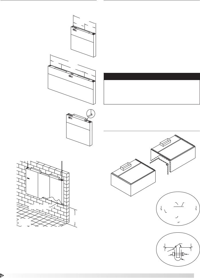
Installing Backsplash Panels
Flat Backsplash Panel |
Insulated Backsplash Panel |
|
Material: Stainless |
Material: Stainless |
1 IN. (25.4 MM) |
|
Insulation: 1 in. (25.4 mm) |
|
|
|
|
|
|
WALL |
HEIGHT
LENGTH
NOTE
•Backsplash length up to 47.25 inches (1200.15 mm) wide ship in one piece; panel lengths over
47.25 inches (1200.15 mm) ship in multiple pieces when panel height is <66 inches (1674.4 mm) or >80 inches (2032 mm).
•Backsplash length up to 48 inches (1219.2 mm) wide ship in one piece; panel lengths over 48 inches (1219.2 mm) ship in multiple pieces when panel height is ≥66 inches (1676.4 mm) or ≤80 inches (2032 mm).
1.After hood is hung into position, slide the flat flange of the backsplash panel behind the back of the hood. If the hood is provided with flat backsplash panels, divider bars will be provided. Install divider bars between panels as shown in the flat backsplash panel section view.
2.After the backsplash panel and dividers have been positioned, drill holes in the panel and fasten to the wall. (Fasteners provided by others). The holes
should be spaced to adequately secure the panel to the wall.
3.Caulk the joints between the hood and the backsplash panel with NSF Approved silicone caulk (GE SCS1009 or its equivalent). Caulk provided by others.
4.Caulk the joint between the backsplash panels when multiple panels are required with NSF Approved (GE SCS1009 or its equivalent). Caulk provided by others.
NOTE
Panels up to 45 in. (1143 mm) wide ship in one piece; over 45 in. (1143 mm) in multiple pieces.
HOOD FRONT PANEL
HOOD END PANEL 
SLIDE FLANGE
BEHIND BACK BACKSPLASH PANEL OF THE HOOD
SECTION VIEW
OF BACKSPLASH
PANEL OVERLAP
Kitchen Hoods • Type I and Type II 11
 Loading...