


Document 483298
Model XRRS
Fire Ready Hood
Installation, Operation and Maintenance Manual
Please read and save these instructions for future reference. Read carefully before attempting to assemble, install, operate or maintain the product described. Protect yourself and others by observing all safety information. Failure to comply with these instructions will result in voiding of the product warranty and may result in personal injury and/or property damage.
Listed to UL Subject 300A
General Safety Information
Personnel should have a clear understanding of these instructions and all applicable, current local and national building and fire codes before installing this product.
NOTE
All service and maintenance on the fire suppression system should be conducted by an authorized fire equipment distributor. Do not tamper with fire suppression components if not instructed to do so.
WARNING
To reduce the risk of fire, electric shock, or injury to persons, observe the following:
•Use this product only in the manner intended by the manufacturer (to cover domestic ranges used for domestic purposes).
•When cutting or drilling into wall or ceiling, do not damage electrical wiring or other hidden utilities.
•Ducted exhaust fans must always be vented to the outdoors.
•Use only rigid, metal ductwork
•This unit must be properly grounded.
To reduce the risk of range top grease fire:
•Never leave the range unattended at high settings. Boil-overs cause smoking and greasy spillovers that may ignite.
•Dense smoke from frying pans indicates cooking oil is near auto ignition – turn the burner down or off.
•Always turn the hood fan ON when part of the cooking surface is on
•Always make sure the hood grease filter is installed before cooking.
•Clean hood grease filter frequently. Do not allow grease to accumulate on filter.
•Always use proper pan size. Use cookware appropriate for the size of the surface element.
•Keep cooking areas clean and clear of combustible materials.
To reduce the risk of injury to persons in the event of a range top grease fire, observe the following:*
•SMOTHER FLAMES with a close-fitting lid, cookie sheet, or metal tray, then turn off the burner. BE CAREFUL TO PREVENT BURNS. If the flames do not go out immediately, EVACUATE AND CALL THE FIRE DEPARTMENT.
•NEVER PICK UP A FLAMING PAN. You may be burned.
•DO NOT USE WATER, including wet dishcloths or towels - violent steam explosion will result.
*Based on “Kitchen Fire Safety Tips” published by NFPA.
AVERTISSEMENT
Pour réduire le risque d’incendie, de choc électrique ou de blessure corporelle, respecter ce qui suit :
•Utiliser uniquement ce produit de la façon prévue par le fabricant (pour couvrir les cuisinières domestiques utilisées à la maison).
•Lors de la découpe ou du perçage de murs ou plafonds, ne pas endommager les câbles électriques et autres conduites masquées.
•Les caissons d’extraction à gaine d’évacuation doivent toujours être évacués vers l’extérieur.
•Utiliser uniquement un réseau de gaine rigide, en métal.
•Cet appareil doit être bien raccordé à la terre.
Pour réduire le disque d’incendie de graisse sur le dessus de la cuisinière :
•Ne jamais laisser la cuisinière sans surveillance à des réglages élevés. Les débordements causent de la fumée et des débordements de graisse qui peuvent s’enflammer.
•Une fumée dense provenant de poêles à frire indiquent que l’huile à friture s’approche de son point d’inflammation spontanée. Régler le bruleur plus bas ou l’éteindre.
•Toujours activer le ventilateur de la hotte lorsqu’une partie de la surface de cuisson chauffe.
•Toujours s’assurer que le filtre de graisse de la hotte est installé avant la cuisson.
•Nettoyer fréquemment la graisse du filtre de la hotte. Ne pas laisser s’accumuler la graisse sur le filtre.
•Toujours utiliser la taille appropriée de poêle à frire. Utiliser une batterie de cuisine proportionnelle à la surface de l’élément.
•Garder propre l’aire de cuisson et dégagée de toute matière combustible.
Observer les points suivants pour réduire le risque de blessures aux personnes advenant un incendie de graisse sur le dessus de la cuisinière :*
•ÉTOUFFER LES FLAMMES à l’aide d’un couvercle ajusté, d’une plaque à biscuits ou d’un plateau en métal, puis fermer le brûleur. S’ASSURER D’ÉVITER DES BRÛLURES. Si les flammes ne s’éteignent pas immédiatement, ÉVACUER LES LIEUX ET APPELER LE SERVICE D’INCENDIE.
•NE JAMAIS SAISIR UNE POÊLE EN FLAMME. Vous pourriez vous brûler.
•NE PAS UTILISER D’EAU, ni de linges à vaisselle ni de serviettes mouillées car il pourrait se produire une violente explosion de vapeur.
*Basé sur les « Kitchen Fire Safety Tips » (Conseils de sécurité sur les incendies de cuisine) publiés par la NFPA
Fire Ready Hood |
1 |

Receiving
Product should arrive in a large carton. Upon receiving the product, check to ensure all items are accounted for by referencing the delivery receipt or packing list. Inspect each crate or carton for shipping damage before accepting delivery. Alert the carrier of any damage detected. The customer will make notation of damage (or shortage of items) on the delivery receipt and all copies of the bill of lading which is countersigned by the delivering carrier. If damaged, immediately contact your Accurex Representative. Any physical damage to the unit after acceptance is not the responsibility of the manufacturer.
Unpacking
Verify that all required parts and the correct quantity of each item have been received. If any items are missing, report shortages to your local representative to arrange for obtaining missing parts. Confirmation of shipment(s) must be limited to only items on the bill of lading.
Parts Checklist
Hood with factory-installed Fire Suppression System
•Finished Top (optional)
•Ceiling Enclosures (optional)
Wall Mounting Bracket with J-Box
External Inline Fan (optional)
•One (1) 50 ft. Plug and Play Cable
Gas Disconnect (optional)
•3/4 inch Gas Valve (plugs into gas shut off assembly box)
•Gas Shut Off Assembly Box with 115VAC Range Receptacle
•Two (2) 10 ft. Plug and Play Cables
Electrical Disconnect (optional)
•Electric Shut Off Assembly Box with 250VAC Range Receptacle
•Two (2) 10 ft. Plug and Play Cables
Shipped Loose User Interface (optional)
•Recessed-Mount J Box
•One (1) 81⁄2 ft. Plug and Play Cable
Manual Pull Station (optional)
•One (1) 30 ft. Plug and Play Cable
Horn Strobe (optional)
•One (1) 8 ft. Plug and Play Cable
Wall Cap (optional)
K-Class Portable Fire Extinguisher (optional)
Fire Test Kit (optional)
Additional: Spare Fuses, Qty. 1 4A Fuse, and Qty. 1 6A Fuse
Handling
Handle hood and accessories in such a manner as to keep from scratching or chipping the coating. Damaged finish may reduce ability of unit to resist corrosion.
Storage and Install Location Requirements
Units are protected against damage during shipment. If the unit cannot be installed and operated immediately, precautions need to be taken to prevent deterioration of the unit during storage. The user assumes responsibility of the unit and accessories while in storage. The manufacturer will not be responsible for damage during storage. The suggestions are provided solely as a convenience to the user.
The ideal environment for the storage of units and accessories is indoors, above grade, in a low humidity atmosphere which is sealed to prevent the entry of blowing dust, rain, or snow. Temperatures should be evenly maintained between 32°F (0°C) and 120°F (49°C). All accessories must be stored indoors in a clean, dry location.
WARNING
The fire suppression system needs to be stored and installed in locations where the temperature will not fall below 32°F (0°C) and not exceed 120°F (49°C) for proper operation.
AVERTISSEMENT
Le système extincteur d’incendie doit être entreposé et installé dans des endroits où la température ne descend pas sous 0°C (32°F) et ne dépasse pas 49°C (120°F) pour un bon fonctionnement.
2 Fire Ready Hood

Table of Contents
Receiving, Unpacking, Parts Checklist, |
|
|
|
Handling and Storage . . . . . . . . . |
. |
. |
. 2 |
Model Number Code. . . . . . . . . . . . |
|
|
3 |
Hood Exploded View. . . . . . . . . . . . |
|
|
3 |
Ventilation and Fan Type Configurations . . . |
. |
. |
4 |
Installation |
|
|
|
General Information and Hood Weights . . |
. |
. |
. 7 |
Dimensional Data and Mounting Bracket. . . . 8 |
|||
Ductwork. . . . . . . . . . . . . . . . . 9 |
|||
Hood . . . . . . . . . . . . . . . . |
. |
. |
9 |
External Fan. . . . . . . . . . . . . |
. |
. |
10 |
Range Disconnect |
|
|
|
Gas / Electric. . . . . . . . . . . . |
. |
. |
10 |
Accessories |
|
|
|
Remote Mounted User Interface. . . . . |
. |
. 11 |
|
Finished Top. . . . . . . . . . . . . . |
|
|
11 |
Ceiling Enclosures. . . . . . . . . . |
. |
. |
11 |
Wall Cap. . . . . . . . . . . . . . . |
|
|
11 |
Manual Pull Station. . . . . . . . . . |
. |
. |
12 |
Horn Strobe. . . . . . . . . . . . . . . 12 |
|||
Fire Extinguisher . . . . . . . . . . . |
. |
. |
12 |
Electrical Connections |
|
|
|
Hood Power. . . . . . . . . . . . . |
. |
. |
13 |
Fan Power - Integral or External Fan. . . . . |
|
|
13 |
Range Disconnect |
|
|
|
Gas / Electric. . . . . . . . . . . . |
. |
13-14 |
|
Accessories |
|
|
|
Remote Mounted User Interface. . . . . |
. |
. 15 |
|
Manual Pull Station. . . . . . . . . . |
. |
. |
15 |
Horn Strobe. . . . . . . . . . . . . . . 15 |
|||
Other External Devices |
|
|
|
Supply Fan Interlock Contacts . . . . . |
. |
. |
15 |
Fire/Fault Contacts . . . . . . . . . . |
. |
. |
15 |
Fan Calibration . . . . . . . . . . . . . |
|
|
16 |
Aiming the Nozzles . . . . . . . . . . |
. |
. |
17 |
Operation. . . . . . . . . . . . . . . . |
|
|
17 |
Unit Pre-Suppression Functions. . . . . |
. |
. |
17 |
Arming the System. . . . . . . . . . . . . . . . . . . . . . . . |
18 |
||
User Interface Navigation |
|
|
|
Hood Lights Operation . . . . . . . . |
. |
. |
20 |
Fan Operation . . . . . . . . . . . . . . 20 Range Operation. . . . . . . . . . . . . 20
Fire System Discharge . . . . . . . . . . |
|
|
21 |
System Faults . . . . . . . . . . . . . . 21 |
|||
Service Settings.. . . . . . . . . |
. . |
21-23 |
|
Fire Prevention Tips. . . . . . . . |
. . |
. |
. 23 |
Service and Maintenance |
|
|
|
Accessing Internal Components. . . . |
. . |
. |
24 |
Fire System Diagnostics . . . . . . . |
. . |
. |
25 |
Fire System Shut Off Sequence . . . . |
. . |
. |
25 |
Fire System Detect Mode . . . . . . |
. . . . 25 |
||
Fire Alarm Sequence. . . . . . . . |
. . . . 26 |
||
After Actuation. . . . . . . . . . . |
. . |
. |
26 |
Routine Maintenance . . . . . . . . . |
. . |
. |
27 |
Troubleshooting . . . . . . . . . . . . . |
|
28-29 |
|
Parts List. . . . . . . . . . . . . . |
. . |
. |
29 |
Our Commitment. . . . . . . . . . |
Backcover |
||
Model Number Code
XRRS - W- 36 - T - E - O - N
Model |
|
|
|
|
|
|
|
|
|
|
|
|
|
|
|
|
|
|
|
|
|
|
|
|
|
|
NFPA 101 Compliance |
|
|
|
|
|
|
||||||||||||||||||||||
Residential |
|
|
|
|
|
|
|
|
|
|
|
|
|
|
|
|
|
|
|
X - Noncompliant |
|||||||
Range |
|
|
|
|
|
|
|
|
|
|
|
|
|
|
|
|
|
|
|
N - Compliant |
|||||||
Suppression |
|
|
|
|
|
|
|
|
|
|
|
|
|
|
|
|
|
|
|
|
|||||||
Configuration |
|
|
|
|
|
|
|
|
|
|
|
|
|
|
|
|
|
|
|
|
|
|
|
||||
|
|
|
|
|
|
|
|
|
|
|
|
|
|
|
|
|
|
|
|
|
|
|
|||||
W - Wall |
|
|
|
|
|
|
|
|
|
|
|
|
External Fan Type |
||||||||||||||
I - Island |
|
|
|
|
|
|
|
|
|
|
|
|
|||||||||||||||
|
|
|
|
|
|
|
|
|
|
|
|
D - Inline Duct |
|||||||||||||||
|
|
|
|
|
|
|
|
|
|
|
|
|
|
|
|
|
|
|
|
|
|
|
|||||
Length |
|
|
|
|
|
|
|
|
|
|
|
|
|
|
|
|
|
|
|
|
|
O - Fan by Others |
|||||
|
|
|
|
|
|
|
|
|
|
|
|
|
|
|
|
|
|
|
|
|
|
|
|||||
30 inches |
|
|
|
|
|
|
|
|
|
|
|
|
|
|
|||||||||||||
36 inches |
|
|
|
|
|
|
|
|
|
|
|
|
|
|
|||||||||||||
Ventilation |
|
|
|
|
|
|
|
|
|
|
|
|
|
Range Disconnect Type |
|||||||||||||
F - Integral Fan - Front Recirculation |
|
|
E - Electric |
||||||||||||||||||||||||
R - Integral Fan - Rear Discharge |
|
|
G - Gas |
||||||||||||||||||||||||
T - External Fan - Top Discharge |
|
|
|
|
|
|
|
|
|
|
|
||||||||||||||||
Example: XRRS-W-36-T-E-O-N
Accurex XRRS, wall mount, 36 inches long, with top discharge, with electric element disconnect, fan provided by others, NFPA 101 Compliant
Hood Exploded View
FIRE SUPPRESSION TANK AND |
|
|
SOLENOID RELEASE |
|
|
FIRE SUPPRESSION |
INTERNAL EXHAUST FAN |
|
CONTROL BOARD |
||
(FOR FRONT RECIRCULATING |
||
|
||
|
AND REAR DISCHARGE MODELS) |
|
|
WALL MOUNT |
|
|
BRACKET |
|
|
HOOD CONTROLS |
|
|
(PLC, RELAYS, AND |
|
|
TERMINAL BLOCKS) |
TOUCHSCREEN
USER INTERFACE
RECIRCULATING VENT (FRONT RECIRCULATING MODEL)
FIRE SUPPRESSION TEMPERATURE SENSORS (QTY 2)
LED LIGHTS (QTY 2) 
MODEL / SERIAL # |
|
|
INFORMATION |
|
|
STICKER |
|
|
FIRE SUPPRESSION |
GREASE FILTER |
|
DROPS WITH NOZZLES |
||
WALL CLAMP |
||
(QTY 2) |
||
(QTY 2) |
||
|
||
|
HOOD TEMPERATURE |
|
|
SENSOR |
Fire Ready Hood |
3 |

Ventilation and Fan Type Configurations
Roof Cap |
|
(by others) |
|
|
10 in. Ductwork |
|
(by others) |
|
12 in. to 10 in. |
External Inline Fan |
Transition |
(by others) |
|
(provided) |
|
|
10 in. to 12 in. |
|
Transition |
|
(by others) |
Soffit |
|
|
10 in. Ductwork |
Kitchen Cabinets |
(by others) |
|
|
Range Hood |
8 in. to 10 in. |
(provided) |
Transition |
|
(by others) |
|
Airflow |
External Fan | Top Discharge
(with Non-NFPA 101 Compliant Inline Fan)
External Fan |
|
(by others) |
|
|
10 in. Ductwork |
|
(by others) |
Soffit |
|
|
10 in. Ductwork |
Kitchen Cabinets |
(by others) |
|
|
Range Hood |
8 in. to 10 in. |
(provided) |
Transition |
|
(by others) |
|
Airflow |
External Fan | Top Discharge
(with Non-NFPA 101 Compliant Fan by Others)
Roof Cap |
|
(by others) |
|
|
12 in. Ductwork |
|
(by others) |
500 CFM |
|
External Inline Fan |
|
(provided) |
|
Soffit |
|
|
12 in. Ductwork |
Kitchen Cabinets |
(by others) |
|
|
Range Hood |
8 in. to 12 in. |
(provided) |
Transition |
|
(by others) |
Airflow |
|
External Fan | Top Discharge
(with NFPA 101 Compliant 500 cfm Inline Fan)
500 CFM |
|
External Fan |
|
(by others) |
|
|
12 in. Ductwork |
|
(by others) |
Soffit |
|
|
12 in. Ductwork |
Kitchen Cabinets |
(by others) |
|
|
Range Hood |
8 in. to 12 in. |
(provided) |
Transition |
|
(by others) |
|
Airflow |
External Fan | Top Discharge
(with NFPA 101 Compliant 500 cfm Fan by Others)
Soffit 
Kitchen Cabinets
Range Hood
(provided)
Airflow
5 in. x 12 in. Ductwork
(by others)
Wall Cap
(optional)
Integral Fan | Rear Discharge
Soffit 
Kitchen Cabinets
Vent with Charcoal Filter
(provided)
Range Hood
(provided)
Airflow
Integral Fan | Front Recirculation
4 Fire Ready Hood

Wiring Diagram: Electric Disconnect
Fire Ready Hood |
5 |

Wiring Diagram: Gas Disconnect
6 Fire Ready Hood
Installation
WARNING
Failure to affix the mounting bracket to studs correctly can lead to structural damage and/or serious injury. The structural integrity of
the wall is the responsibility of the contractor.
Hood Weight
30 inches |
86 lbs. |
|
|
36 inches |
93 lbs. |
|
|
AVERTISSEMENT
Si le support de fixation est mal posé |
Poids de la hotte |
||
sur les montants, il peut y avoir des |
|
|
|
dommages structuraux et/ou de |
76 cm |
39 kg |
|
graves blessures. L’entrepreneur est |
(30 po) |
(86 lb) |
|
responsable de l’intégrité structurale |
|
|
|
91,4 cm |
42,2 kg |
||
du mur. |
|||
(36 po) |
(93 lb) |
||
|
|
|
|
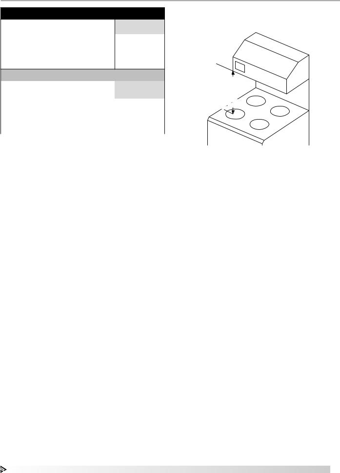
It is recommended that before drywall is hung, all electrical cables that need to be run within the wall should be run through the wall to their corresponding components. Mount the control j-box to line up with the right corner of the hood mounting bracket and run cables for these components into this box through the grommets. Confirm all critical mounting points will need to be secured through studs or utilize dry wall hangers. Hood weight should be supported by at least two (2) studs. Hood needs to be centered above the range and within the height requirements shown. Make sure that with integral fan – rear discharge configurations, the studs and control j-box do not interfere with the rear discharge duct.
After drywall is hung, affix mounting bracket to wall using the necessary field provided fasteners through the critical mounting points.
Minimum Spacing:
24 inches
Maximum Spacing:
30 inches
Measure vertical distance from bottom of hood to cooking surface
Hood to Cooking Surface
Spacing Recommendation
Fire Ready Hood |
7 |
Dimensional Data
|
8.375 |
|
|
3.375 |
2.376 |
C |
|
|
|
8.375 |
7.248 |
2.376 |
|
|
C |
|
|
|
|
|
|
|
|
|
|
|
|
|
|||||||
|
|
|
|
|
|
|
|
|
|
|
|
|
|
|
|
|
|
1.650 |
A |
|
|
|
|
|
|
|
1.650 |
A |
|
|
|
|
|
|
|
3.000 |
B |
|
|
|
|
|
5.114 |
|
3.000 |
|
A |
|
|
|
|
|
5.114 |
|
|
|
|
|
|
|
|
|
|
|
|
|
|
||||
|
|
|
|
|
|
|
|
|
|
|
|
|
|
|
|
|
|
|
|
|
|
|
|
A |
1.223 |
12.275 |
|
|
E |
|
2.750 |
A |
|
|
1.223 |
4.625 |
E |
|
|
2.750 |
4.625 |
|
A |
A |
E |
|
|
||||||
|
A |
A |
|
|
|
|
|
|
|
12.275 |
|||||||
|
|
|
|
|
|
E |
|
|
|
|
|
|
|
|
|
||
|
|
|
|
|
|
|
|
|
|
|
|
|
|
|
|
||
|
|
|
|
|
|
|
|
|
|
A |
|
A |
|
|
A |
|
|
D |
B |
|
|
A |
A |
B |
D |
|
D |
|
A |
|
|
D |
|||
|
|
|
|
|
|
|
|
|
|
|
|
||||||
1.813 |
|
|
4.000 |
|
|
1.813 |
|
|
4.813 |
4.000 |
4.000 |
|
|
4.000 |
4.813 |
|
|
4.000 |
|
|
4.000 |
|
|
|
|
|
|
|
|
||||||
|
|
|
|
|
|
|
|
|
|
33.625 |
|
|
|
||||
|
|
|
|
27.625 |
|
|
|
|
|
|
|
|
|
|
|||
|
|
|
|
|
|
|
|
|
|
|
|
|
|
|
|
||
|
|
|
|
|
|
|
|
|
|
|
|
|
|
|
|
|
|
|
30 Inch Integral Fan | Front Recirculation |
|
|
36 Inch Integral Fan | Front Recirculation |
|
||||||||||||
|
8.375 |
|
|
3.375 |
2.376 |
C |
|
|
|
8.375 |
7.248 |
2.376 |
|
|
C |
|
|
|
|
|
|
|
|
|
|
|
A |
|
|
|
|
|
|
|
|
1.650 |
A |
|
|
|
|
|
|
|
1.650 |
|
|
5 x 12 INCH |
|
|
|
|
|
|
|
|
5 x 12 INCH |
|
|
|
|
|
|
|
|
|
|
5.114 |
|||
|
|
|
|
|
|
5.114 |
|
3.000 |
|
|
REAR DISCHARGE |
|
|
|
|||
3.000 |
B |
|
|
REAR DISCHARGE |
|
|
|
A |
|
FAN DUCT |
|
|
|
|
|||
|
|
|
FAN DUCT |
|
|
|
|
|
|
|
|
|
|
|
|||
|
|
|
|
|
|
A |
1.223 |
|
|
|
|
|
2.750 |
A |
|
|
1.223 |
4.625 |
|
E |
|
2.750 |
12.275 |
4.625 |
|
E |
A |
A |
E |
|
|
||||
|
A |
A |
|
|
|
|
|
|
|
|
12.275 |
||||||
|
|
|
|
|
|
E |
|
|
|
|
|
|
|
|
|
||
|
|
|
|
|
|
|
|
D |
|
A |
A |
A |
|
|
A |
D |
|
D |
|
|
|
A |
A |
|
D |
|
|
|
|
||||||
B |
|
|
B |
|
|
|
|
|
|
|
|
|
|
||||
|
|
|
|
|
|
|
|
|
|
|
|
|
|
|
|
||
1.813 |
|
|
|
4.000 |
|
|
1.813 |
|
|
4.813 |
4.000 |
4.000 |
|
|
4.000 |
4.813 |
|
4.000 |
|
|
|
4.000 |
|
|
|
|
33.625 |
|
|
|
|||||
|
|
|
|
27.625 |
|
|
|
|
|
|
|
|
|
|
|||
|
|
|
|
|
|
|
|
|
|
|
|
|
|
|
|
|
|
|
30 Inch Integral Fan | Rear Discharge |
|
|
|
36 Inch Integral Fan | Rear Discharge |
|
|||||||||||
|
8.375 |
|
|
3.375 |
2.376 |
C |
|
|
|
8.375 |
7.248 |
2.376 |
|
|
C |
|
|
|
|
|
|
|
|
|
|
|
|
|
|||||||
1.650 |
A |
|
|
|
|
|
|
|
1.650 |
A |
|
|
|
|
|
|
|
3.000 |
B |
|
A |
|
|
5.114 |
|
3.000 |
|
A |
|
|
|
|
|
5.114 |
|
|
|
|
|
|
|
|
|
|
|
|
|
||||||
|
|
|
6.389 |
|
|
|
|
|
|
|
|
|
|
|
|||
|
|
|
|
|
A |
1.223 |
12.275 |
|
|
|
|
6.389 |
A |
|
|
1.223 |
|
4.625 |
E |
|
A |
|
A |
4.625 |
|
E |
A |
|
A |
E |
|
|
|||
|
|
|
|
|
|
|
|
|
|
12.275 |
|||||||
|
|
|
|
|
|
E |
|
|
|
|
|
|
|
|
|
||
|
|
|
|
|
|
|
|
|
|
|
|
|
|
|
|
||
|
|
|
|
|
|
|
|
|
|
A |
|
A |
|
|
A |
|
|
D |
B |
|
|
A |
A |
B |
D |
|
D |
|
A |
|
|
D |
|||
|
|
|
|
|
|
|
|
|
|
|
|
||||||
1.813 |
|
|
4.000 |
|
|
1.813 |
|
|
4.813 |
4.000 |
4.000 |
|
|
4.000 |
4.813 |
|
|
4.000 |
|
|
4.000 |
|
|
|
|
33.625 |
|
|
|
||||||
|
|
|
|
27.625 |
|
|
|
|
|
|
|
|
|
|
|||
|
|
|
|
|
|
|
|
|
|
|
|
|
|
|
|
||
|
|
|
|
|
|
|
|
|
|
|
|
|
|
|
|
|
|
|
30 Inch External Fan | Top Discharge |
|
|
|
36 Inch External Fan | Top Discharge |
|
|||||||||||
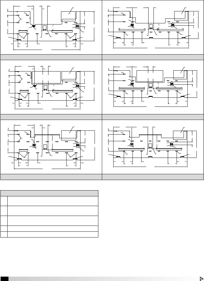
Dimensions shown are in inches.
Mounting Bracket Key
ACritical mounting points must be secured to studs or drywall hangers
BUtilize one of these two critical points for securing to stud or drywall hangers. (Three total)
CLocation for factory provided 4 inch high x 6 inch wide x 3-1/2 inches deep control j-box
DHood support tabs
EHood latch connections
1.Before mounting, situate mounting bracket on wall making sure critical mounting points are met and distance from bottom of bracket to cooking surface is between 24 and 30 inches.
2.Cut out space in wall for factory provided control j-box and secure in place.
3.Secure mounting bracket to wall using the proper field provided fasteners through all critical mounting points shown in the drawings.
8 Fire Ready Hood

Ductwork (if applicable)
Running ductwork will be required for hoods configured for external fans. A small rectangular piece of duct spanning the width of the wall will be required for integral fan – rear discharge configurations (discharging through the back wall). Check the individual hood drawings to see what fan type is provided with your system.
Hood Length |
NFPA 101 |
Ventilation |
External Fan |
CFM |
Duct Size |
Duct Length |
|
(in.) |
Compliance |
Type |
(Minimum) |
(Maximum) |
|||
|
|
||||||
|
|
|
|
|
|
|
|
|
No |
Integral Fan – Front Recirculating |
Not applicable |
250 |
Not applicable |
Not applicable |
|
|
|
|
|
|
|
|
|
|
No |
Integral Fan – Rear Discharge |
Not applicable |
250 |
5 x 12 in. |
2 ft. |
|
|
|
|
|
|
|
|
|
|
No |
External Fan - Top Discharge |
Inline |
250 |
10 in. round |
35 ft. |
|
|
(diameter) |
||||||
|
|
|
|
|
|
||
|
|
|
|
|
|
|
|
|
No |
External Fan - Top Discharge |
Fan by Others |
250 |
10 in. round |
External fan by others should be sized |
|
30 |
(diameter) |
based on hood and duct static pressure |
|||||
|
|
|
|
||||
|
|
|
|
|
|
|
|
|
Yes |
Integral Fan - Rear Discharge |
Not applicable |
500 |
5 x 12 in. |
2 ft. |
|
|
|
|
|
|
|
|
|
|
Yes |
External Fan - Top Discharge |
Inline |
500 |
12 in. round |
35 ft. |
|
|
(diameter) |
||||||
|
|
|
|
|
|
||
|
|
|
|
|
|
|
|
|
Yes |
External Fan - Top Discharge |
Fan by Others |
500 |
12 in. round |
External fan by others should be sized |
|
|
(diameter) |
based on hood and duct static pressure |
|||||
|
|
|
|
|
|||
|
|
|
|
|
|
|
|
|
No |
Integral Fan – Front Recirculating |
Not applicable |
300 |
Not applicable |
Not applicable |
|
|
|
|
|
|
|
|
|
|
No |
Integral Fan – Rear Discharge |
Not applicable |
300 |
5 x 12 in. |
2 ft. |
|
|
|
|
|
|
|
|
|
|
No |
External Fan - Top Discharge |
Inline |
300 |
10 in. round |
35 ft. |
|
|
(diameter) |
||||||
|
|
|
|
|
|
||
|
|
|
|
|
|
|
|
|
No |
External Fan - Top Discharge |
Fan by Others |
300 |
10 in. round |
External fan by others should be sized |
|
36 |
(diameter) |
based on hood and duct static pressure |
|||||
|
|
|
|
||||
|
|
|
|
|
|
|
|
|
Yes |
Integral Fan - Rear Discharge |
Not applicable |
500 |
5 x 12 in. |
2 ft. |
|
|
|
|
|
|
|
|
|
|
Yes |
External Fan - Top Discharge |
Inline |
500 |
12 in. round |
35 ft. |
|
|
(diameter) |
||||||
|
|
|
|
|
|
||
|
|
|
|
|
|
|
|
|
Yes |
External Fan - Top Discharge |
Fan by Others |
500 |
12 in. round |
External fan by others should be sized |
|
|
(diameter) |
based on hood and duct static pressure |
|||||
|
|
|
|
|
|||
|
|
|
|
|
|
|
All ductwork will need to be provided in the field. Installing ductwork must be done by qualified person(s) in accordance with all applicable codes and standards, including fire-rated construction. All ductwork, per IMC Section 505 should be constructed of sheet metal, have smooth inner walls, be air tight, and be independent of all other exhaust ductwork systems.
To minimize static pressure losses and promote adequate airflow, minimize duct run lengths where possible.
For external fan configurations, duct should be connected to the 8 inch collar adapter on the hood mounting bracket. Transitions should be utilized to expand duct to duct size minimum requirements noted in table above.
Hood
1.Remove hood from crating. Remove the grease filter.
2.Carefully lift it onto the lower hood tabs on the wall mounting bracket.
2.While holding the hood up, hook the safety cable to the chain link on the mounting bracket and screw nut to close the link. The hood is now in the service position.
3.To put the hood into operation position, lift the hood up, and one at a time re-hook the clamps and pull the clamps tight until they lock. Make sure the safety bolt lever is located inside the notch in the hood mounting bracket. See page 22 for pictures and more information.
4.When all construction is complete, remove protective plastic sheeting from hood stainless steel. Clean (using alcohol and rag) and polish (using stainless steel polish) the hood. When cleaning or polishing, be sure to wipe with the grain and not against it.
Fire Ready Hood |
9 |
 Loading...