

Page 1
Document 470391
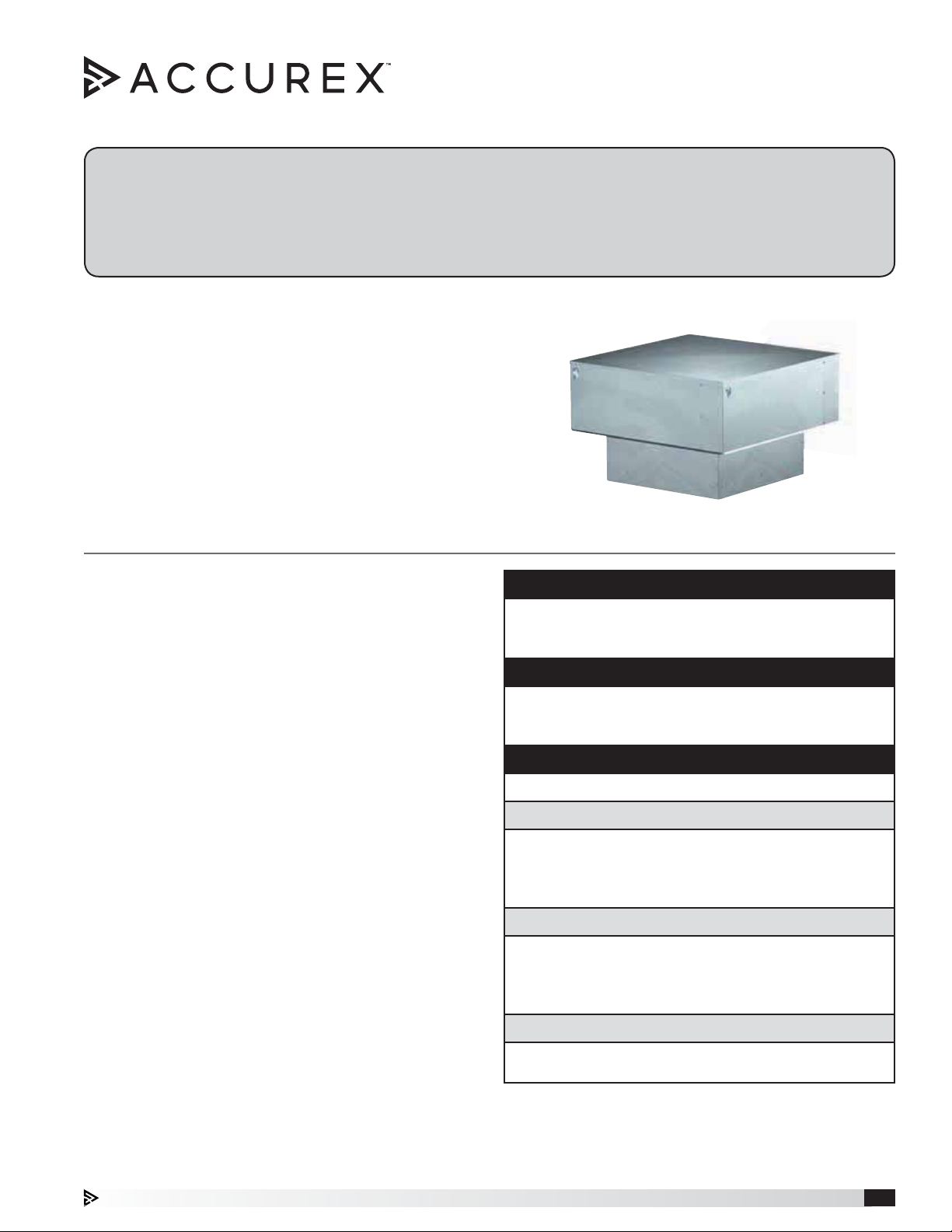
Model XRS
Roof Supply Fan
Installation, Operation and Maintenance Manual
Please read and save these instructions for future reference. Read carefully before attempting to assemble, install,
operate or maintain the product described. Protect yourself and others by observing all safety information. Failure
to comply with these instructions will result in voiding of the product warranty and may result in personal injury
and/or property damage.
Centrifugal Supply Fans
Fans are specifically designed for filtered roof supply
applications. Fans feature permanent washable
aluminum filters for years of reliable use and doublewidth forward-curved wheels for high efficiency and
low sound. Available with straight-sided hood or
architectural louvered penthouse housing.
General Safety Information
Only qualified personnel should install this fan.
Personnel should have a clear understanding of these
instructions and should be aware of general safety
precautions. Improper installation can result in electric
shock, possible injury due to coming in contact with
moving parts, as well as other potential hazards. Other
considerations may be required if high winds or seismic
activity are present. If more information is needed,
contact a licensed professional engineer before moving
forward.
1. Follow all local electrical and safety codes, as well as
the National Electrical Code (NEC) and the National
Fire Protection Agency (NFPA), where applicable.
Follow the Canadian Electric Code (CEC) in Canada.
2. The rotation of the wheel is critical. It must be free
to rotate without striking or rubbing any stationary
objects.
3. Motor must be securely and adequately grounded.
4. Do not spin fan wheel faster than max cataloged fan
RPM. Adjustments to fan speed significantly affect
motor load. If the fan RPM is changed, the motor
current should be checked to make sure it is not
exceeding the motor nameplate amps.
5. Do not allow the power cable to kink or come in
contact with oil, grease, hot surfaces or chemicals.
Replace cord immediately if damaged.
6. Verify that the power source is compatible with the
equipment.
7. Never open access doors to a duct while the fan is
running.
DANGER
Always disconnect, lock and tag power source before
installing or servicing. Failure to disconnect power
source can result in fire, shock or serious injury.
CAUTION
When servicing the fan, motor may be hot enough
to cause pain or injury. Allow motor to cool before
servicing.
CAUTION
Precaution should be taken in explosive atmospheres.
DANGER
Pour écarter les risques d’incendie, de choc électrique
ou de blessure grave, veiller à toujours débrancher,
verrouiller et étiqueter la source de courant avant
l’installation ou l’entretien.
ATTENTION
Lors de toute intervention sur la soufflante, le moteur
peut être suffisamment chaud pour provoquer une
douleur voire une blessure. Laisser le moteur refroidir
avant toute maintenance.
ATTENTION
Faire preuve de précaution dans les atmosphères
explosives.
Roof Supply Fan 1
Page 2
Receiving
Upon receiving the product, check to ensure all items
are accounted for by referencing the delivery receipt or
packing list. Inspect each crate or carton for shipping
damage before accepting delivery. Alert the carrier
of any damage detected. The customer will make
notification of damage (or shortage of items) on the
delivery receipt and all copies of the bill of lading which
is countersigned by the delivering carrier. If damaged,
immediately contact your Representative. Any physical
damage to the unit after acceptance is not the
responsibility of the manufacturer.
Unpacking
Verify that all required parts and the correct quantity
of each item have been received. If any items are
missing, report shortages to your local representative to
arrange for obtaining missing parts. Sometimes it is not
possible that all items for the unit be shipped together
due to availability of transportation and truck space.
Confirmation of shipment(s) must be limited to only
items on the bill of lading.
Handling
Fans are to be rigged and moved by the lifting brackets
provided or by the skid when a forklift is used. Location
of brackets varies by model and size. Handle in such
a manner as to keep from scratching or chipping the
finish. Damaged finish may reduce the ability of the fan
to resist corrosion.
Fans should never be lifted by the shaft, fan housing,
motor, belt guard, windband or accessories.
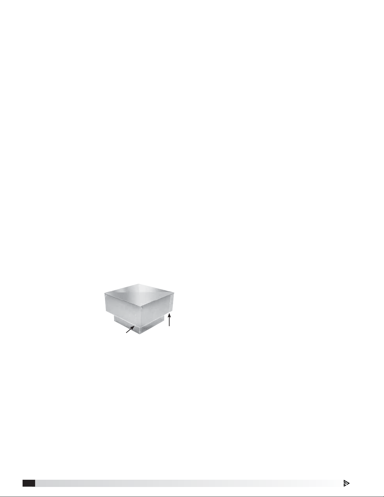
Lifting
Lifting the fans must
be done with care to
avoid damaging the
housing. For model
Straight-housing
models attach four
lifting devices under
the outer housing,
each device beneath
the vertical row of fasteners as depicted in Figure 1.
Lifting devices should be a minimum of 3 inches wide to
avoid damaging the sheet metal housing.
Do not lift this model near the center of the outer
housing.
For Louvered Penthouse models attach a minimum of
four lifting devices under an exterior louver panel, each
device near the corner of the louvered housing.
Figure 1
Lift Here
Lift Here
Storage
Fans are protected against damage during shipment. If
the unit cannot be installed and operated immediately,
precautions need to be taken to prevent deterioration of
the unit during storage. The user assumes responsibility
of the fan and accessories while in storage. The
manufacturer will not be responsible for damage during
storage. These suggestions are provided solely as a
convenience to the user.
Indoor - The ideal environment for the storage of
fans and accessories is indoors, above grade, in a
low humidity atmosphere which is sealed to prevent
the entry of blowing dust, rain or snow. Temperatures
should be evenly maintained between 30° to 110°F
(-1° to 43°C). Wide temperature swings may cause
condensation and “sweating” of metal parts. All
accessories must be stored indoors in a clean, dry
atmosphere.
Remove any accumulations of dirt, water, ice or snow
and wipe dry before moving to indoor storage. To avoid
“sweating” of metal parts allow cold parts to reach room
temperature. To dry parts and packages use a portable
electric heater to get rid of any moisture buildup. Leave
coverings loose to permit air circulation and to allow for
periodic inspection.
The unit should be stored at least 3½ in. (89 mm) off the
floor on wooden blocks covered with moisture proof
paper or polyethylene sheathing. Aisles between parts
and along all walls should be provided to permit air
circulation and space for inspection.
Outdoor - Fans designed for outdoor applications may
be stored outdoors, if absolutely necessary. Roads or
aisles for portable cranes and hauling equipment are
needed.
The fan should be placed on a level surface to prevent
water from leaking into the fan. The fan should be
elevated on an adequate number of wooden blocks so
that it is above water and snow levels and has enough
blocking to prevent it from settling into soft ground.
Locate parts far enough apart to permit air circulation,
sunlight and space for periodic inspection. To minimize
water accumulation, place all fan parts on blocking
supports so that rain water will run off.
Do not cover parts with plastic film or tarps as these
cause condensation of moisture from the air passing
through heating and cooling cycles.
Fan wheels should be blocked to prevent spinning
caused by strong winds.
Roof Supply Fan2
Page 3
Inspection & Maintenance During Storage
While in storage, inspect fans once per month. Keep a
record of inspection and maintenance performed.
If moisture or dirt accumulations are found on parts,
the source should be located and eliminated. At each
inspection, rotate the wheel by hand ten to fifteen
revolutions to distribute lubricant in motor and bearings.
If paint deterioration begins, consideration should
be given to touch-up or repainting. Fans with special
coatings may require special techniques for touch-up or
repair.
Machined parts coated with rust preventive should be
restored to good condition promptly if signs of rust
occur. Immediately remove the original rust preventive
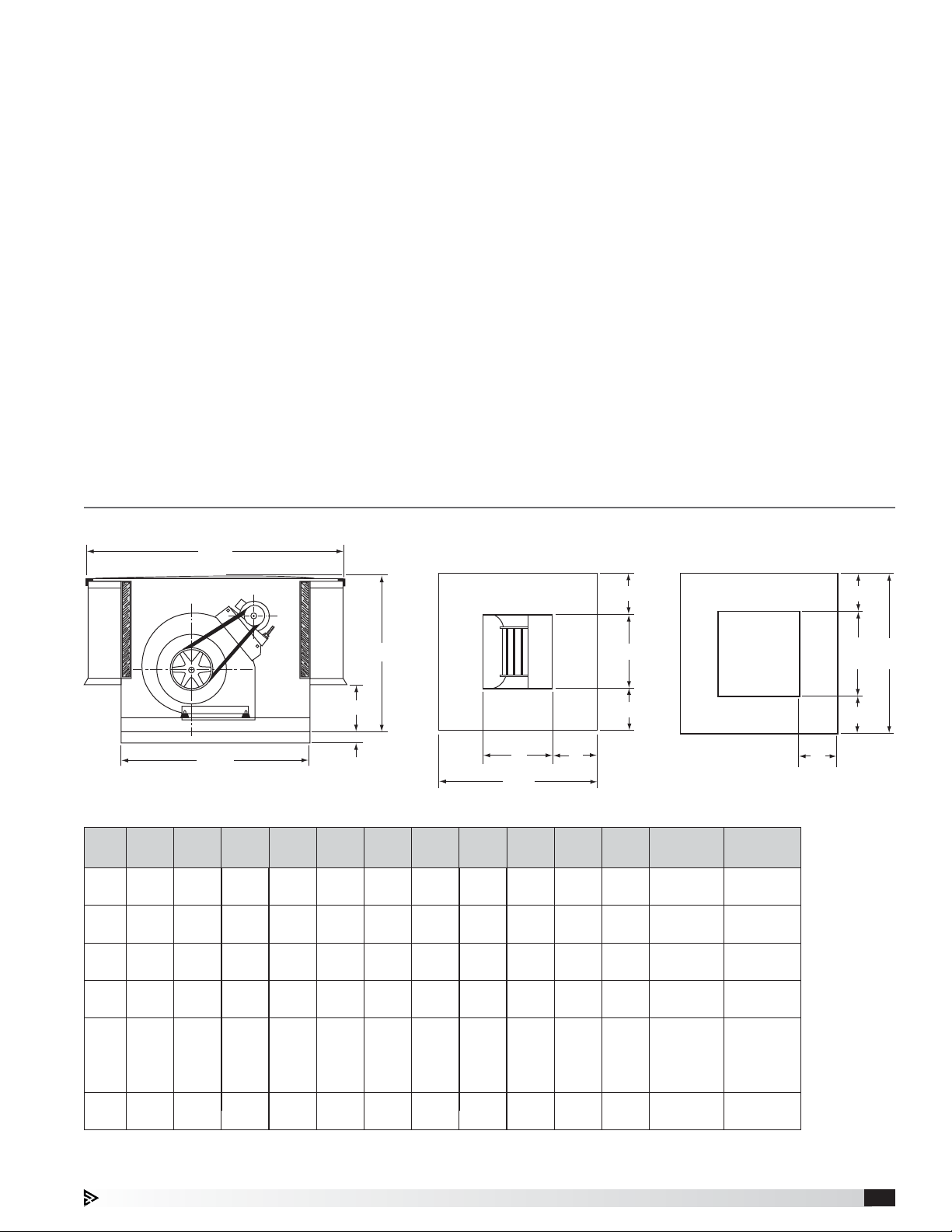
Dimensional Data
coating with petroleum solvent and clean with lint-free
cloths. Polish any remaining rust from surface with
crocus cloth or fine emery paper and oil. Do not destroy
the continuity of the surfaces. Thoroughly wipe clean
®
with Tectyl
506 (Ashland Inc.) or the equivalent. For
hard to reach internal surfaces or for occasional use,
consider using Tectyl
®
511M Rust Preventive, WD-40®
or the equivalent.
Removing from Storage
As fans are removed from storage to be installed in their
final location, they should be protected and maintained
in a similar fashion until the fan equipment goes into
operation.
B SQ.
C
D
21/2 in.
SQ.
A
Fan
SizeA SQ.B SQ.
26 351⁄8 231⁄4 101⁄4 121⁄4 103⁄4 75⁄8 67⁄8 241⁄2 121⁄4 61⁄8 (4) 12x20 145
90
(660) (892) (591) (260) (311) (273) (194) (175) (662) (311) (156) (305x508) (66)
100
120
150
180
200
30 411⁄8 231⁄4 101⁄4 135⁄8 117⁄8 91⁄16 83⁄16 281⁄2 141⁄4 71⁄8 (4) 12x25 173
(762) (1045) (591) (260) (346) (302) (230) (208) (724) (362) (181) (305x635) (78.5)
34 471⁄8 271⁄4 101⁄4 161⁄8 137⁄8 101⁄16 815⁄16 321⁄2 181⁄4 71⁄8 (4) 16x25 225
(864) (1197) (692) (260) (410) (352) (256) (227) (826) (464) (181) (406x635) (102)
40 531⁄8 311⁄4 101⁄4 191⁄8 161⁄2 111⁄4 107⁄16 381⁄2 201⁄4 91⁄8 (8) 16x20 336
(1016) (1349) (794) (260) (486) (419) (286) (265) (978) (514) (232) (406x508) (152)
46 611⁄8 341⁄4 121⁄4 221⁄2 191⁄2 101⁄8 113⁄4 441⁄2 261⁄4 91⁄8
(1168) (1153) (870) (311) (571) (495) (257) (298) (1130) (667) (232) (4) 20x20 (181)
52 731⁄8 391⁄4 121⁄4 231⁄4 251⁄4 133⁄8 143⁄8 501⁄2 301⁄4 101⁄8 (8) 20x25 620
(1321) (1857) (997) (311) (591) (641) (340) (365) (1283) (768) (257) (508x635) (281)
CDFGHJ
All dimensions are in inches (millimeters). Pounds (kg).
Base of Unit
A
G
SQ.
K
SQ.L SQ.
Optional Duct Adapter
J
F
J
H
Nominal
M
Filter
(4) 16x20
(406x508)
(508x508)
Weight
400
M
L
SQ.KSQ.
M
M
Roof Supply Fan 3
Page 4

Installation
Electrical Connection
Move the fan to its intended location and fasten it
securely through mounting holes provided in the
fan base. Shims may be necessary depending
upon thickness of the roofing material. For ducted
applications, an optional duct adapter (if provided)
is attached and holds the ductwork in place prior to
installing the unit. The diagram below shows a typical
installation with prefab roof curb and ductwork.
Access to the motor compartment is made by releasing
four latches which secure the cover. The cover should
be placed in an area where wind will not blow it off the
roof.
Typical Installation
Prepunched mounting
holes and 21⁄2 in. skirt
to aid in installation.
Ductwork (by others)
Duct adapter (optional)
allows ductwork to
be completed prior to
setting unit on curb.
Roof curb
The electrical supply must be compatible with the fan
motor with regard to voltage, phase and amperage
capacity. Moreover, the electrical supply line must
be properly fused and conform to local and national
electrical codes.
Electrical lead-in wires should be routed through the
pre-punched hole in the optional duct adapter (if
provided) and the punched hole in the bottom of the fan
housing. Electrical wires must be located so as not to
rub on moving components. The electrical supply line
is connected to an optional safety disconnect switch (if
provided) or wired directly to the motor.
Wiring should be secured inside the fan to prevent
interference with the drive components. All wiring must
conform to local and national codes.
1
1
1
⁄2
⁄2
⁄2
Recommended
Roof Opening
15
(381)
17
(432)
21
(533)
23
(584)
29
(737)
33
(838)
Duct Size ID
12
(305)
14
(356)
18
(457)
20
(508)
26
(660)
30
(762)
Fan Size Curb Size*
90
100
120
150
180
200
All dimensions are in inches (millimeters).
* Recommended curb size shown is outside curb dimension without roofing
and flashing.
Note: In cases where extreme snow depths may be encountered, extended
base may be required to raise unit or condensation pans may be required in
ductwork.
24
(662)
281⁄2
(724)
321⁄2
(826)
38
(978)
441⁄2
(1130)
50
(1283)
Nominal
Damper Size
12 x 12
(305x305)
14 x 14
(356x356)
18 x 18
(457x457)
20 x 20
(508x508)
26 x 26
(737x737)
30 x 30
(838x838)
Roof Supply Fan4
Page 5

Mounting for Severe Duty Installations
IMPORTANT
Installation instructions for seismic ratings are only recommendations. Final design must be determined by
Structural Engineer of Record (SEOR) including requirements for curb construction, mounting of unit to curb and
mounting of curb to structure.
Fan to Curb: Three (3) fasteners are required
per side on all sides. Must be equally spaced.
Roof Supply Fan
1.25
1.25
Curb Corner
Anchor Detail
Roof Curb
Model SD, SDP, GPF or Equivalent
18 ga. Min.
24 in. (610 mm) Tall Max.
Welded Steel Construction
Seismic Ratings
Curb to Deck: Fasteners need to be located on two
opposite ends of the curb.
Roof Curb Roof Curb
3/8 in. (10 mm) S.S. Hilti Kwik Bolt 3
Expansion Anchors
Min. 2-1/2 in. (64 mm) Engagement
2000 Min. PSI
Concrete
Concrete
Deck Anchoring
Roof Curb
Wood Timber
Min. 4 in. (102 mm)
Nominal Thickness
Min. G = 0.42
G = specific gravity
of lumber
Deck Anchoring
Timber Anchoring
1/4 in. - 14 Self-Drilling Screw
Min. 1/2 in. (13 mm) of Threads Through
Roof Truss
1/8 in. (3 mm) Thick
or 12 ga. Min.
Steel
3/8 in. (10 mm) Lag Bolt (Zinc Plated)
Min. 3 in. (76 mm) Thread Engagement
Fan Size Curb Cap Size
26x26 to 34x34
(660x660 to 864x864 mm)
40x40
(1016x1016 mm)
46x46 to 52x52
(1168x1168 to 1321x1321 mm)
26x26 to 34x34
(660x660 to 864x864 mm)
40x40
(1016x1016 mm)
46x46 to 52x52
(1168x1168 to 1321x1321 mm)
26x26 to 34x34
(660x660 to 864x864 mm)
40x40
(1016x1016 mm)
46x46 to 52x52
(1168x1168 to 1321x1321 mm)
Concrete
Steel
Timber
90, 100, 120
150
180, 200
90, 100, 120
150
180, 200
90, 100, 120
150
180, 200
All dimensions are in inches (millimeters).
Fastener Size
and Type
3/8-inch S.S.
Hilti Kwik Bolt 3
Expansion
Anchors
1/4 in. - 14
Self-Drilling
Screw
3/8-inch
Lag Bolt
(zinc plated)
Fasteners
Per Side
Total
Fasteners
36
48
510
36
48
510
36
48
510
Roof Supply Fan 5
Page 6

Pre-Starting Checks
DANGER
Disconnect and secure to the “off” position all
electrical power to the fan prior to inspection or
servicing. Failure to comply with this safety precaution
could result in serious injury or death.
DANGER
Pour écarter les risques de blessure grave ou de mort,
débrancher et verrouiller l’alimentation électrique en
position « Arrêt » avant tout contrôle ou entretien.
Units with motor and drives shipped separate, refer to
Motor Mounting Instructions included in hardware bag.
Check all fasteners and set screws for tightness. Rotate
the fan wheel by hand to assure it turns freely and is
centered between the inlets. Check pulleys and belts for
proper alignment to avoid premature belt wear, noise,
vibration and power loss. Motor and fan pulleys must be
parallel and in alignment, see Figure 2.
CORRECT WRONG WRONG WRONG
Direction of fan wheel rotation is critical. A fan wheel
rotating in the wrong direction will result in reduced
airflow, motor overloading and
a
t
t
i
o
o
n
R
possible burnout. Check wheel
rotation by momentarily turning
the fan on.
Rotation should be in the same
direction as airflow at the outlet.
See housing and wheel example
in Figure 3.
Figure 3
Airflow
IMPORTANT
Supply fans should be operated only when attached
to the completed system. Without proper static
pressure loading, the motor may be overloaded and
burnout may occur.
Figure 2
Adjustable motor pulley is set at the factory for the fan
RPM specified. Fan speed can be increased by closing
or decreased by opening the adjustable motor pulley.
Two groove variable pitch pulleys must be adjusted an
equal number of turns open. Any increase in fan speed
results in an increase in horsepower required for the
motor. Motor amperage should always be checked
and compared to nameplate rating when changing fan
speed.
Roof Supply Fan6
Page 7

Maintenance
DANGER
Disconnect and secure to the “off” position all
electrical power to the fan prior to inspection or
servicing. Failure to comply with this safety precaution
could result in serious injury or death.
DANGER
Pour écarter les risques de blessure grave ou de mort,
débrancher et verrouiller l’alimentation électrique en
position « Arrêt » avant tout contrôle ou entretien.
To preserve the reliability and performance designed
into the fan, regularly scheduled maintenance should be
performed. Items to be checked at each maintenance
interval are filters, belts, bearings, fasteners, lubrication
and removal of dust and dirt.
Filters
One-inch washable aluminum mesh filters are standard
on both models. Optional two-inch filters may be
supplied on some fans. Filters should be cleaned on a
regular basis for optimum efficiency.
To remove the filters, first remove the fan cover by
releasing the four latches. Place the cover in an area
where wind will not blow it off the roof. The filters can
be lifted out and washed in a mild detergent solution.
If desired, an adhesive spray available at most filter
distributors can be applied to increase filter efficiency.
Belts
Belt tension should be checked two times during the
first 24 hours of operation and during each scheduled
maintenance thereafter. Premature belt failures are
frequently caused by improper belt tension, either too
tight or loose. The proper belt tension for operating a
V-belt is the lowest tension at which the belt will not
slip at peak load conditions. For initial tensioning, belt
deflection should be 1/64 inch for each inch of belt
span, determined by
using moderate thumb
pressure half way
between pulley centers.
For example, the belt
deflection should be 1/2
inch if the belt span is
32inches, see Figure 4.
Figure 4
Belt tension can be adjusted by loosening the motor
plate hinge bolts and adjusting the jack screws as
required. All units are supplied with either a painted
steel motor bracket or a galvanized motor plate for
larger motor frames. To adjust belt tension on units
equipped with the painted steel motor bracket, simply
adjust the single jack screw.
For units equipped with a galvanized motor plate, both
jack screws must be adjusted equally. Check pulley and
belt alignment after adjusting belt tension; Figure 2.
Belt Span
Deflection =
Belt Span
64
Lubrication
Fan bearings on all models are permanently lubricated.
Motor bearings equipped with grease fittings should be
lubricated in accordance with instructions on the motor
nameplate. Motors without grease fittings are lubricated
for life.
Cleaning
Motors and fan wheels require periodic cleaning to
remove dust and dirt which may accumulate. Motor
cleaning should be limited to the exterior surface only.
Removing dust and dirt from the motor housing assists
in motor cooling and prolongs motor life. Motors should
never be sprayed with steam, water or solvents.
Fan wheels which are left to accumulate dust and dirt
will have poor air performance, loss of efficiency and
possible damaging vibration due to an unbalanced
condition.
Periodic cleaning is a good investment in preserving the
reliability and performance designed into the fan.
Roof Supply Fan 7
Page 8

Parts List
Each fan bears a manufacturer’s nameplate with model number and serial number embossed. This information
will assist the local representative and the factory in providing service and replacement parts. Before taking any
corrective action, make certain unit is not capable of operation during repairs.
CAUTION
A fan manufactured with an explosion resistant motor
does not certify the entire unit to be explosion proof.
Refer to ULListing Mark for the fans approved usage.
Filters
Shaft Pulley
Belt
Vibration Isolators (4)
La présence d’un moteur antidéflagrant sur un
ventilateur ne garantit pas que tout l’appareil est
antidéflagrant. Pour connaître les emplois autorisés
de l’appareil, voir son marquage de conformité UL.
Blower Unit
*Motor Plate
Motor
Motor Pulley
Blower Mounting Angle
CAUTION
*Galvanized motor plate shown.
Painted steel motor bracket used on
units with smaller motor frame sizes.
Our Commitment
Our Commitment
As a result of our commitment to continuous improvement, Accurex reserves the right to change specifications
without notice.
Product warranties can be found online at accurex.com, either on the specific product page or in the Warranty
section of the website at Accurex.com/Resources/Warranty.
P.O. Box 410 Schofield, WI 54476
Phone: 800.333.1400 • Fax: 715.241.6191
Parts: 800.355.5354 • accurex.com
476370 • Grease Trap, Rev. 2, February 2013 Copyright 2014 © Greenheck Fan Corporation8 470391 • XRS, Rev. 4, January 2019 Copyright 2019 © Accurex, LLC8
 Loading...