

Page 1
Document 470404
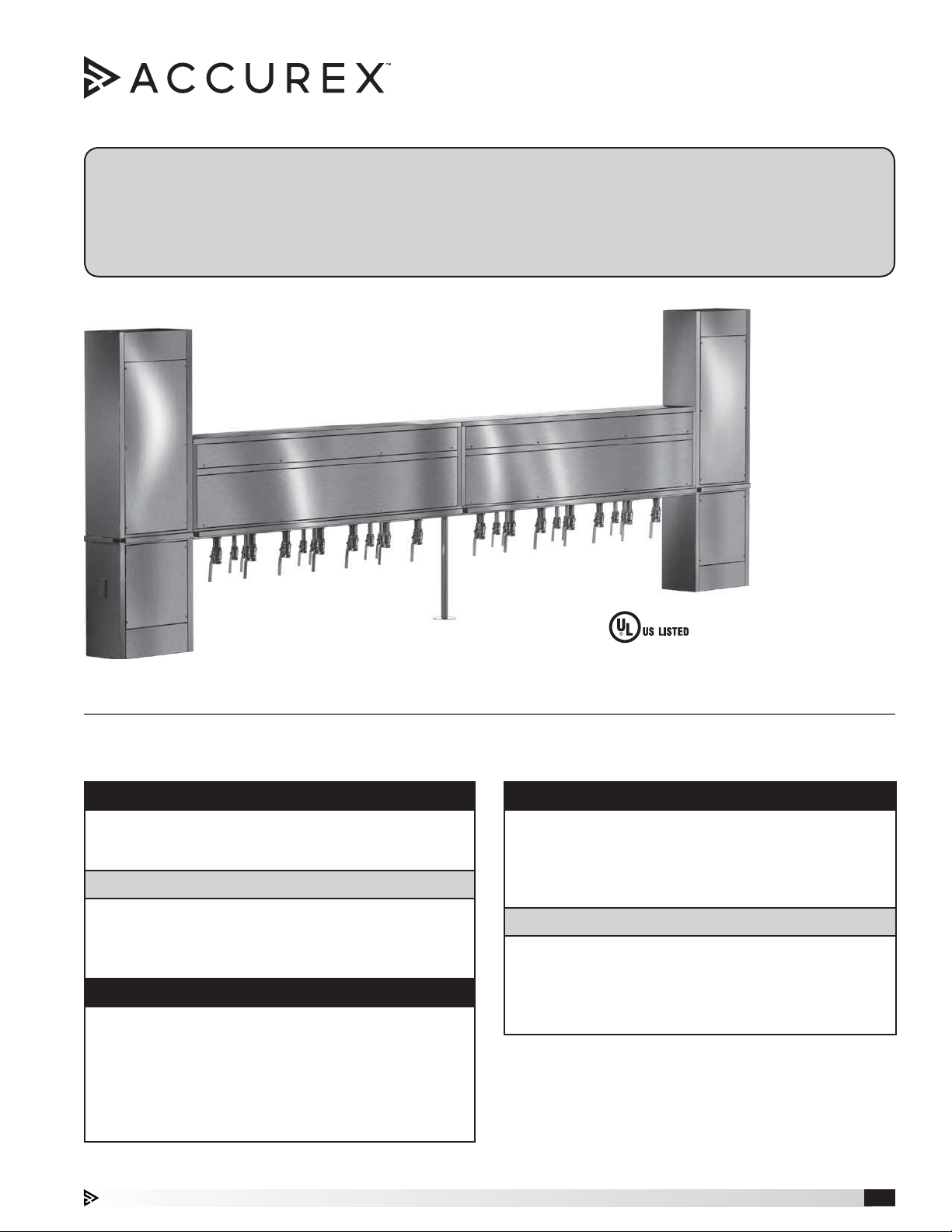
Model XM
Utility Distribution System
Installation, Operation and Maintenance Manual
Please read and save these instructions for future reference. Read carefully before attempting to assemble, install,
operate or maintain the product described. Protect yourself and others by observing all safety information. Failure
to comply with these instructions will result in voiding of the product warranty and may result in personal injury
and/or property damage.
UL Listed to UL 891
General Safety Information
Only qualified personnel should install and service this system. Personnel should have a clear understanding of these
instructions and all applicable local and national building and fire codes.
DANGER
Always disconnect lock and tag power source before
installing or servicing. Failure to disconnect power
source can result in fire, shock or serious injury.
DANGER
Pour écarter les risques d’incendie, de choc électrique
ou de blessure grave, veiller à toujours débrancher,
verrouiller et étiqueter la source de courant avant
l’installation ou l’entretien.
NOTE
Follow all local electrical and safety codes, as well
as the National Electrical Code (NEC), and the
latest edition of the National Fire Protection Agency
Standard for Ventilation Control and Fire Protection
of Commercial Cooking Operations (NFPA 96). Follow
the Canadian Electrical Code and ULC-S650 if
installing this product in Canada.
Improper installation, adjustment, alteration, service
or maintenance can cause property damage, injury
or death. Read the installation, operating, and
maintenance instructions thoroughly before installing
or servicing this equipment.
Les poses, réglages, modifications, entretiens et
réparations incorrects peuvent provoquer des dégâts
matériels, des blessures ou la mort. Bien lire les
instructions de pose, d’utilisation et d’entretien avant
l’installation ou l’entretien de ce matériel.
WARNING
AVERTISSEMENT
Utility Distribution System 1
Page 2

Table of Contents
Receiving, Handling and Storage ............... 2
Product Overview ............................ 3
Unit Configuration ........................... 4
Option and Accessory Descriptions ............. 5
Installation
Uncrating ................................. 6
Mounting and Securing. . . . . . . . . . . . . . . . . . . . . . 6
Plumbing ................................. 7
Electrical ................................7-8
Main Incoming Service ...................... 8
Control Power ............................. 8
Fire System Integration ...................... 8
Hose Installation Instructions ................. 9
Start-Up
Testing ................................... 9
Fire Fuel Shut-Off, optional ................... 10
Overcurrent Protection, optional ............... 10
Operation ................................. 11
Troubleshooting ............................ 11
Our Commitment ........................... 12
Receiving
Upon receiving the equipment, check for both obvious
and hidden damage. If damage is found, record all
necessary information on the bill of lading and file a
claim with the final carrier. If any items are missing,
report shortages to your local representative to arrange
for obtaining missing parts. Confirmation of shipment(s)
must be limited to only items on the bill of lading. Any
physical damage to the unit or missing parts found after
acceptance is not the responsibility of the manufacturer.
Handling
Move the unit slowly and carefully using the forklift
pockets on either end. Be sure to completely support
the entire unit length when moving. Do not lay the
crated unit on its side.
Storage
Units are protected against damaged during shipment.
If the unit cannot be installed and operated immediately,
precautions need to be taken to prevent deterioration of
the unit during storage. The user assumes responsibility
of the unit and accessories while in storage.
The ideal environment for storage of the UDS and
accessories is indoors, above grade in a clean, dry
atmosphere that is sealed from the elements. Store unit
standing up; do not lay the unit on its side.
Utility Distribution System2
Page 3
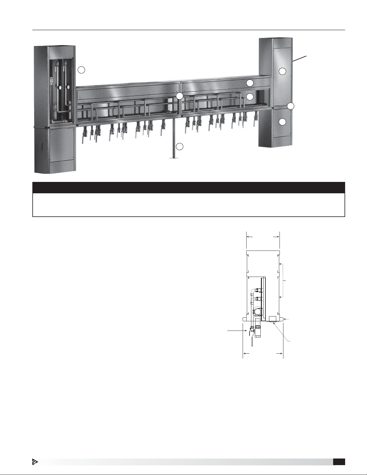
Product Overview
2
Panel Board
Breaker System
4
5
Electrical Option
1
3
6
7
4
NOTE
Utility Distribution System, or UDS, are a highly configurable and customizable product. Some instances in this
manual may make references to features which may or may not be present on your equipment. Please consult
your submittal and electrical drawings which are also provided to determine which portions of this manual apply.
1. Utility Chase – Horizontal component that is
connected between the two (2) vertical risers. This
brings the utilities to the cooking equipment in a
clean convenient way.
2. Utility Riser – Vertical components that house major
utilities, control center, fire fuel shut-off, and field
connections.
3. Pedestal (optional) – Supporting component for the
chase under the field joint(s) at the chase when the
UDS has reached a predetermined length.
4. Access Panels – Doors on the UDS that allow
access for installation or maintenance.
5. Electrical Section of Chase – All electrical (typically
wire bus or bus bar) is fed through this portion of the
utility chase. This portion is intentionally closed off
to the plumbing section of the utility chase. Electrical
sections are accessible through removable panels.
6. Plumbing Section of Chase – All plumbing (typically
includes gas, hot water, and cold water) is fed
through this portion of the utility chase. This portion
is intentionally closed off to the electrical section of
the utility chase. Plumbing sections are accessible
through removable panels.
7. Bumper Strip - Bump out strips mounted about
waist-high on the UDS to prevent cooking equipment
that is not fastened to the floor from hitting and
damaging the UDS.
Gas and Water
Plumbing Drops with
Equipment Shutoff
Per Customer Request
Typical Section View Through
Typically
12 inches
16 Gauge Stainless Steel
Removable Panels
(Both Sides on Island UDS)
Full-Length
Bumper Guards
(Both Sides on Island UDS)
Receptable Plates
Typically
14.6 inches
Utility Distribution System 3
Page 4
Unit Configuration
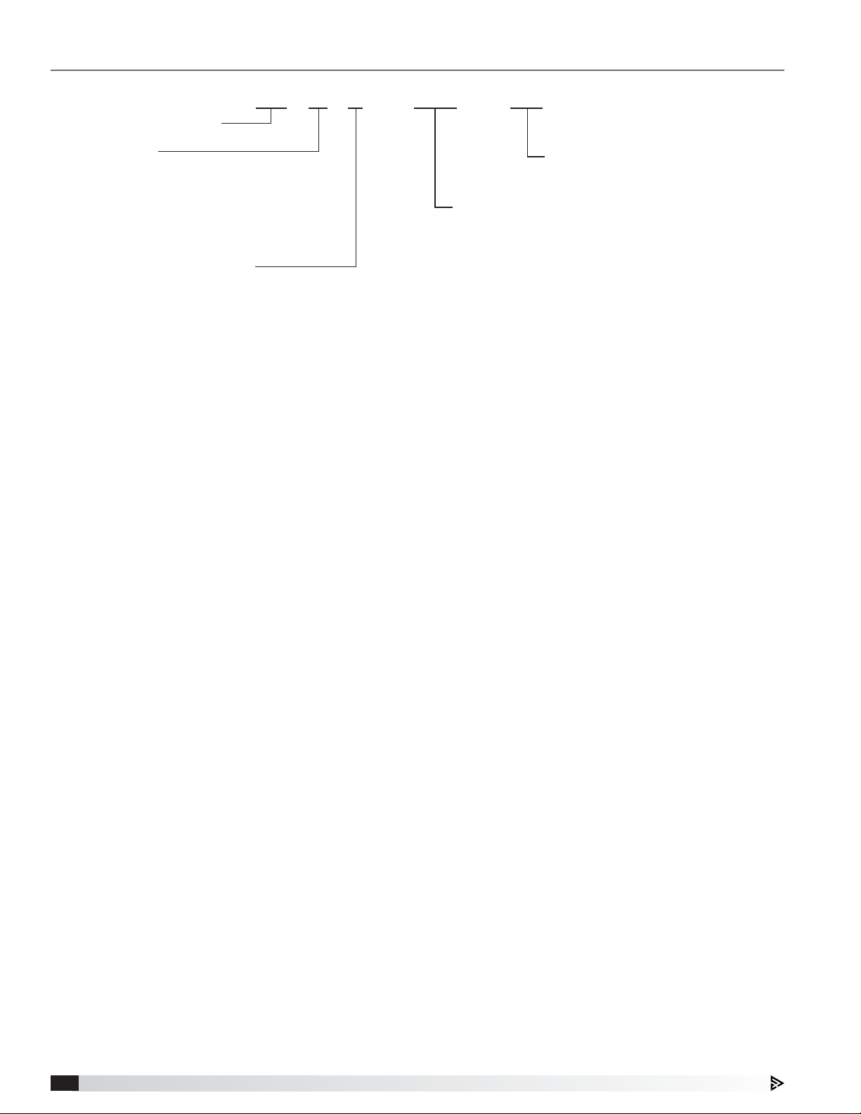
Utility Distribution System
XM W V - GHC - 132
UDS Style
C - Chase
I - Island
O - Overhead
P - Electric Pole
U - Utility Column
W - Wall
Electrical Services
B - Buss Bar
H - Point of Use with Receptacles
N - None
R - Receptacle(s) Only
V - Panelboard with Receptacles
1. Manufacturer
a. Model XM, Modular FlexConnect™ Utility
Distribution System Series
2. Style
a. (W) Wall – Mounted up against a wall with
appliances on one side only; no bumper or
electrical outlets on opposite side of utility chase (if
provided with electrical service).
b. (I) Island – Appliances on both sides; bumper and
electrical outlets on both sides of utility chase (if
provided with electrical service).
3. Electrical
a. (V) Panelboard – Electrical service panelboard
in either the right or left most riser. Typically,
this includes a shunt trip or under-voltage main
breaker and individual branch breaker(s) for
each equipment receptacle. Breakers, wiring,
and receptacles are all provided by the factory.
20A convenience outlets are provided on both
left and right riser ends. Equipment receptacles
are fastened in the specified location under the
horizontal chase.
b. (H) Point-of-Use – Incoming electrical service riser
is located on the left or right most riser. Typically,
this includes a shunt trip or under-voltage main
breaker in the riser. Individual branch breakers
for each piece of equipment are located in the
horizontal chase directly inline with the equipment
receptacle. 20A convenience outlets are provided
on both left and right riser ends.
c. (R) Receptacles Only – Unit shall include
equipment receptacles fastened in the specified
location under the horizontal chase. 20A
convenience outlets are provided on both left
and right riser ends. All wiring and/or conduit is
provided by others in the field.
Unit Length
Overall unit length in inches
Piped Services
1 to 4 characters depending upon plumbing services
A - Compressed Air
C - Cold Water
D - Drain and Vent
F - Filtered Water
G - Gas
H - Hot Water
L - Chilled Water
S - Steam/Condensate Return
4. Gas
a. (G) Gas Manifold – Either a single service through
one riser, or a looped service through both risers
is provided. Gas line is fed through the plumbing
section of the utility chase by the factory, with
gas drops every 12 inches. Typically, these are
provided with quarter turn ball valve disconnects if
used for specific appliances.
5. Water
a. (H) Hot Water – Either 3/4 or 1 inch hot water
manifold is fed through the plumbing section of
the utility chase by the factory with drops every
24inches. Typically, these are provided with
quarter turn ball valve disconnects if used for
specific appliances.
b. (C) Cold Water – Either 3/4 or 1 inch cold water
manifold is fed through the plumbing section of
the utility chase by the factory with drops every
24inches. Typically, these are provided with
quarter turn ball valve disconnects if used for
specific appliances.
6. Length
a. Length – Total length of the UDS, including risers
and utility chase by the factory.
Utility Distribution System4
Page 5

Option and Accessory Descriptions
Chilled Water Line – Additional plumbing manifold to
provide chilled water. This manifold will be insulated.
Compressed Air Line – Additional plumbing manifold
to provide compressed air.
E-Stop Emergency Shut Off – Button provided to shut
off electricity (and gas, depending on gas valve type) to
the cooking equipment.
Equipment Cord Set – Combination cord and plug
assembly that can be provided to wire into an appliance
and be plugged into the UDS.
Equipment Hoses – Flexible hoses with steel mesh
covers and quick disconnects for cooking equipment.
Fill Faucet – UDS mounted pot filler, typically used to fill
commercial kettles with water.
Filler Panel between Risers – Stainless steel paneling
to close off the area above and below the horizontal
chase.
Filtered Cold Water – Option that includes water
filter(s) within the UDS to filter contaminants out of the
cold water supply. This may be required for certain
appliances like combination ovens and steamers.
Gas Reset – Manual reset button and indicator light.
Gasketed Construction – Gasketing provided to cover
all stainless steel edges within the UDS.
Ground Fault Protection – Receptacles and breakers
with added electrical components to protect people
from line to ground electrocution.
Hose Reel – A retractable hose reel to keep a pre-rinse
spray valve assembly in a tight, contained space on the
UDS.
Looped Gas – Configuration where gas manifold is fed
from one riser, through the chase, and out the other
riser. This provides more balanced gas supply, and is
sometimes necessary with systems that need to deliver
a large amount gas for the cooking line up.
Main Breaker with Shunt Trip – Main breaker designed
to trip during a fire or if the emergency stop button is
pressed. This is standard with UDS configured with
either point-of-use or panel board electrical service.
Main Breaker with Undervoltage Trip – Available
upon special design request, this breaker is designed
to trip upon a loss or dip in control voltage. This may be
required per a local code or jurisdiction.
Make-Up Air through UDS – UDS designed with
supply collars and perforation below the horizontal
chase to provide dedicated make-up air for the kitchen
hoods around the UDS.
Peak Top on Chase – Option to include a peaked
chase top to help prevent grease from building up on
the top of the chase.
Pin and Sleeve Receptacles and Plugs – Special
type of twist-to-lock receptacle and plug that provides
a durable, fused interlock in wet and corrosive
environments.
Prison Package – For kitchens within a prison, it
is important that the system is built without any
components that could be removed and used as a
weapon. For the UDS, this typically incorporates tamper
proof fasteners, gasketed construction, and while-inuse receptacle covers.
Restraining Cables – Cable that attaches from the UDS
to the movable appliance. This helps prevent appliances
with gas and other plumbing connections from being
pulled too far away and damaging the hoses. Length of
the restraining cables need to be shorter than the length
of the plumbing hoses.
Riser Extensions – Riser extensions paneling that
extends from the top of the riser to the top of the hood
or hood enclosure panels.
Riser Extension from top
of riser to top of hood or
enclosure panels
Slim Line Unit – UDS that is 8 inches wide or narrower,
instead of the standard 12 inch width.
Status Lights – Status lights provided by each branch
circuit breaker to indicate power.
Steam/Condensate Return – Additional plumbing
manifold to provide steam/condensate return for
steamers and other types of cooking equipment.
Super Swivel – Equipment hoses designed with
a swivel adapter to prevent damage to the hose if
equipment is moved frequently.
Twist Lock Receptacles – Receptacles designed to
slip together then twist to lock into place. This keeps
the plug and receptacle from pulling apart; also waterresistant.
UDS Mounted Hood Controls – Hood and fan controls,
from fan switches to systems including motor starters or
variable frequency drives can be built into the UDS.
Uninterruptable Power Supply (UPS) – Power supply
for the control circuit within a UDS that is able to “ride
through” any temporary building power outages.
NOTE
Other options are available. For more information,
contact your local manufacturer’s representative.
Utility Distribution System 5
Page 6

Installation
Uncrating
Use caution when uncrating the UDS. Depending on
the configuration, switches and indicator lights may be
provided and protrude from the unit, use caution when
moving the unit or moving equipment around the unit.
Mounting and Securing
1. Refer to drawings and equipment layout to
determine the orientation of the UDS. Unit
orientation is important as the unit is typically
configured with drop locations specific to an initial
set and order of appliances.
2. Gently lift the unit off of the pallet and position into
place. If the UDS is broken into multiple sections, lift
each section into place.
3. Remove all access panels on raceway, riser and
pedestal to reveal internal plumbing, electrical, and
internal flanges.
4. Once sections are in position, join field joints (if
any) between sections by bolting internal flanges
together and applying NSF approved silicone caulk
(GE SCS-1009, or equivalent) over seams. Caulk is
not provided.
Chase Sections
bolt together with
(9) 5/16 inch bolt and nuts
(typically 3 top, 3 back and 3 front)
8. If a kitchen hood or hoods is/are intended to be
mounted on either side of the UDS, hang and level
the hood(s) at this time. Make sure the hood is
mounted at the specific height shown in the drawing
provided.
9. Adjust riser collar(s) if supplied and as necessary
by loosening nuts on weld studs inside riser collars,
adjusting as necessary, and re-tightening nuts.
Loosen (2) 1/4-20 nuts inside of
risers (on opposite corners) to
adjust collars. Tighten nuts when
collar is in appropriate position.
Collar slides up
and down when
fasteners are
loosened.
10. If applicable, make connections between the hood
and hood controls to the utility distribution system.
Once the fire system has been installed, tested, and
armed, wire the fire system into the UDS as well.
11. Once all electrical connections have been
completed on the hood, and all electrical and
plumbing services have been connected to the
UDS, install all filler panels and enclosure panels (if
provided) between the hoods and above the hood
and UDS.
Bottom
Filler Panel
End Filler Panel
(Each End)
5. If applicable, drill holes through unit as shown
on the drawing and secure properly to wall. This
typically is required for systems that are not
provided with risers.
6. If applicable, fasten risers to the floor.
Fasten UDS to floor
using pre-drilled holes
Bottom
of Riser
FASTENERS PROVIDED BY OTHERS
on bottom flanges.
7. Complete all plumbing and electrical installation
procedures. Reference drawing, and see pages 7
and 8.
Utility Distribution System6
Page 7

Plumbing
1. If system has field joint(s), plumbing must be
connected at the joint(s) before attaching main
service. Connect corresponding pipes by aligning
unions and tightening securely.
NOTE
Do not force the threaded connections or pull sections
together by tightening the plumbing fittings.
Field Jointed Chase
Threaded unions at field joint.
Staggered for accessibility.
2. Connect all plumbing stub-ins to the main lines.
Provide all necessary nipples, couplers, unions, etc.
to make neat and proper connections.
3. Connect all hose assemblies (if provided) to the
appropriate equipment as shown on the drawing.
Provide all necessary L’s and nipples to make neat
and proper appearance. (Please see hose installation
instructions on page 9).
4. During testing, check all plumbing for leaks and
tighten as required.
5. Replace all access panels.
NOTE
This equipment is to be installed with adequate
backflow protection to comply with federal, state or
local codes having jurisdiction.
Electrical
1. If system has field joint(s), wiring must be
interconnected at the joint(s) before attaching main
service.
a. If provided with bus bar, connect the
corresponding bus bars together with the brass
bolts and nuts provided.
b. If provided with wire bus, connect number-
matched wires from one section to the other
using the corresponding terminal blocks
provided.
Field Jointed Chase
Connections beyond field joint
are number-matched, then
folded back for shipment.
2. Connect the electrical service(s) to the system as
follows:
a. Attach main service wires to the corresponding
terminals on the main breaker and neutral bar.
b. Connect all control wiring as shown in the
electrical drawing provided with the unit.
Additional information is shown on page 8.
c. Check and tighten connections if necessary.
d. Connect all cord assemblies to the appropriate
equipment as shown on submittal drawing. Cut
cord assemblies if necessary to make a neat
appearance.
e. Test the electrical systems for proper operation.
f. Replace all access panels.
Utility Distribution System 7
Page 8

Electrical, continued
NOTE
All field wiring of electrical equipment must be done to
meet all NEC and local electrical codes.
The extent of field wiring required will depend on the
configuration of the UDS. A few options are broken
out in the next portion of this manual. Reference the
UDS electrical drawings provided with the unit for more
specific wiring details.
Main Incoming Service
UDS appliance power is typically provided from
120/208/3 and/or 460/3 60Hz power from the building
directly to the main breaker(s) within the electrical riser
from above. Service size should be shown on the UDS
drawing.
• 120/208V/3PH to main breaker, neutral lug, and
grounding bar
• 460V/3PH to main breaker and grounding bar
Control Power
The UDS needs a power source to operate all control
components. This source must come from a separate,
non-shunted breaker from the building; the power must
remain constant, even during the event of a fire.
• 120VAC, 10 amp circuit to terminals H and N
120V/1PH/60HZ
from 10A REMOTE BREAKER
L1
N
NH
from REMOTE BREAKER
*
GROUND BAR
from REMOTE BREAKER
120/208V/3PH/60HZ
L2
L1
H
HH
CBM1
208V
SERVICE A
MAIN BREAKER
460V/3PH/60HZ
L2
L1
H
HH
L3
L3
N
NEUTRAL LUG
Fire System Integration
A dedicated fire system microswitch or dry SPDT set
of fire contacts needs to be wired to the UDS. During a
fire, this will shut off fuel to the cooking equipment per
NFPA 96.
• Common on microswitch to terminal C1
• Normally-closed to terminal NC1
• Normally-open to terminal NO1
120V/1PH/10A
to FIRE SYSTEM MICROSWITCH
FS1
NC
NO
NONC
C
*
GROUND BAR
Utility Distribution System8
CBM3
460V
SERVICE B
MAIN BREAKER
Page 9

Hose Installation Instructions
1. Check sizes and quantity of hose assemblies as
shown on the drawing.
2. Make sure all plumbing 1/4 turn ball valves are in the
off position. When the handle is in-line with the pipe,
the valve is in the “on” position. When the handle is
at a right angle to the pipe, it is in the “off” position.
3. Connect all hose assemblies to the appropriate
equipment as shown on the drawing. Provide and
install necessary plumbing fittings to present a neat
appearance and to ensure that the hose assemblies
do not touch floor. To connect hoses to quick
disconnects, pull back sleeve, and push plug into
socket. To disconnect, pull back sleeve, unlocking
the coupling.
4. To ensure proper installation and minimal wear of
hoses, follow the examples shown below:
Do not offset
couplings. This
creates torsional
twisting and
undue strain
causing
premature
failure.
Allowing a sharp
bend strains and
twists the metal
hose to a point
of early failure at
the coupling.
Couplings and hose
should be installed
in the same plane
as shown.
This is the correct way
to install metal hose
for vertical traverse.
Note the single natural
loop.
Start-Up
Testing
1. After installation has been completed, including
plumbing and electrical connections, replace all
access panels in the electrical chase.
2. Make sure all breakers (including the main) are in
the off position.
3. Make sure all service and appliance ball valves are
closed.
4. Slowly open the cold water main supply ball valve
(if provided). Check for leaks between the main
ball valve and appliance ball valves. Once check is
complete, close the main supply valve.
5. Repeat step 4 for hot water and steam valves (if
provided), as well as any other plumbing valves
except for gas (if provided).
6. Turn on main service circuit breakers.
7. Turn on each branch breaker and check the status
lights (if provided) and GFCI receptacles connected
to each breaker. Continue with all branch breakers.
8. Slowly open the gas main supply ball valve until fully
open (if provided). If equipped with an electric gas
valve, press the RESET button on the fire fuel shut
off panel to allow gas to flow to the appliance ball
valves. Check for leaks.
9. At this point, hook up all equipment (plug and
cordsets, plumbing hoses). Refer to Hose
Installation Instructions found on this page.
10. Open all appliance ball valves.
11. With everything on, test appliances for proper
operation and look for any leaks.
12. If provided, test fire fuel shut-off (see page 10 for fire
fuel shut off operation).
Closing in the
diameter at the
coupling creates
double bends
causing work
fatigue failure
of fittings.
Maintain the minimum
or larger bending
diameter between
the couplings for
longest life.
Utility Distribution System 9
Page 10

Fire Fuel Shut-Off (optional)
Overcurrent Protection (optional)
Sequence of Operation
GAS "ON"
RESET
E-STOP
ALARM
after the fire system is returned to the cocked (armed)
position under normal operating conditions, the button
marked gas reset must be pressed to allow gas to flow
to all gas operated equipment. A “GAS ON” pilot light
will illuminate when gas is allowed to flow to all gas
operated equipment.
1. Electricity
Actuation of the fire system will trip
all circuit breakers equipped with
the fire-fuel shut off feature and deenergize the corresponding outlets.
Typically, this occurs only on the main
service shunt trip breaker(s) in the
UDS electrical riser. If equipped, the
audible alarm in the UDS will sound.
After the fire system is returned to the
cocked (armed) position under normal
operating conditions, these circuit
breakers will remain de-energized
until manually reset.
2. Gas
Actuation of the fire system will stop
all gas flow to the gas operated
equipment. If equipped, the audible
alarm in the UDS will sound. If the
UDS is supplied with a mechanical
gas valve, after the fire system is
returned to the cocked (armed)
position under normal operating
conditions, gas will flow to all gas
operated equipment. If the UDS is
supplied with an electric gas valve,
Testing
1. Turn all individual equipment controls to the OFF
position before attempting to connect or disconnect
any cord and plug assembly. After the cord and plug
assembly is connected, equipment may be turned
ON.
2. When the circuit breaker is in the OFF position,
the receptacle operation indicator light will not
be illuminated. To energize the outlet, turn the
circuit breaker to the ON position. The receptacle
operation indicator light will turn ON.
3. To test the connection plate, turn the circuit breaker
to the ON position and press the PUSH TO TEST
button. The circuit breaker will automatically turn to
the OFF position and the outlet will be de-energized.
4. Turn the circuit breaker back to the ON position and
the outlet will be energized. The equipment is now
ready for operation.
Current Sensor Adjustment
NOTE
Ground fault nuisance tripping may occur on certain
pieces of equipment. If this situation occurs, follow
these steps
1. Turn off ALL main services to raceway.
2. Carefully remove the screws securing the access
panel.
3. Locate the ground fault sensing relay and adjust the
potentiometer slightly clockwise.
4. Carefully replace the access panel and tighten
securely.
5. Test the circuit breaker and appliance.
IMPORTANT
After the gas has been reset, all pilot lights must be
re-lit. Failing to re-light pilots will cause gas to flow
into the kitchen.
Emergency Stop
Depressing the emergency stop switch will trip the main
shunt trip breaker(s), and stop all gas flow to the gas
operated equipment (if provided with an electric gas
valve). To reset, pull this emergency stop switch out,
then press the RESET button. The main circuit breaker
must then be reset (turned to the OFF, then to the ON
position) to re-energize the outlets.
IMPORTANT
After the gas has been reset, all pilot lights must be
re-lit. Failing to re-light pilots will cause gas to flow
into the kitchen.
Utility Distribution System10
NOTE
If intermittent tripping continues, contact the factory
for further instruction.
Page 11

Operation
Under normal operation, appliances should remain powered unless:
a. a fire or fire test occurs, or
b. the emergency stop is pressed.
If provided with fan or light controls, buttons to control the lights and/or fans will be provided. Pressing these
buttons will operate hood lights and fans. For more information, reference the drawings provided with the UDS.
Troubleshooting
Problem: Main breaker trips.
Has the main breaker been reset properly? Turn the main breaker completely off, then into the on position.
Is the breaker too small? Check the breaker size and service load and consult the UDS drawings.
Faulty wiring? Check the wiring and fire microswitch wiring.
Faulty breaker Replace main circuit breaker
Problem: Branch breaker trips.
Has the branch breaker been reset properly? Turn the branch breaker completely off, then into the on position.
Current sensor needs adjustment. If UDS is supplied with over current protection, the sensor in the raceway may
need adjustment. See page 10 for instruction on adjusting current sensor.
Problem: Main breaker will not reset.
Fire system in fire position Fire system must be reset.
Fire system microswitch is not connected Connect fire microswitch to UDS. See UDS drawings for details.
Problem: Electric gas valve will not open.
Is the system in fire condition? Check fire microswitch connections and fire system status.
Problem: Water and/or gas is not working.
Are the manual shut off valves in the
service risers on?
Are the appliance quick disconnects
attached?
Check valves to see if they are on.
Check quick disconnects behind appliances for proper installation.
Utility Distribution System 11
Page 12

Our Commitment
Our Commitment
As a result of our commitment to continuous improvement, Accurex reserves the right to change specifications
without notice.
Product warranties can be found online at accurex.com, either on the specific product page or in the Warranty
section of the website at Accurex.com/Resources/Warranty.
P.O. Box 410 Schofield, WI 54476
Phone: 800.333.1400 • Fax: 715.241.6191
Parts: 800.355.5354 • accurex.com
12
470404 • UDS Model XM, Rev. 2, July 2018 © 2018 Accurex, LLC12
 Loading...