

Page 1
Document 482584
Grease Trapper ESP™
Kitchen Exhaust Pollution Control System
Installation, Operation and Maintenance Manual
Please read and save these instructions for future reference. Read carefully before attempting to assemble, install,
operate or maintain the product described. Protect yourself and others by observing all safety information. Failure
to comply with these instructions will result in voiding of the product warranty and may result in personal injury
and/or property damage.
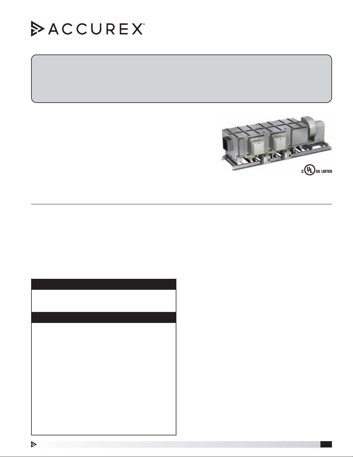
Grease Trapper ESP™
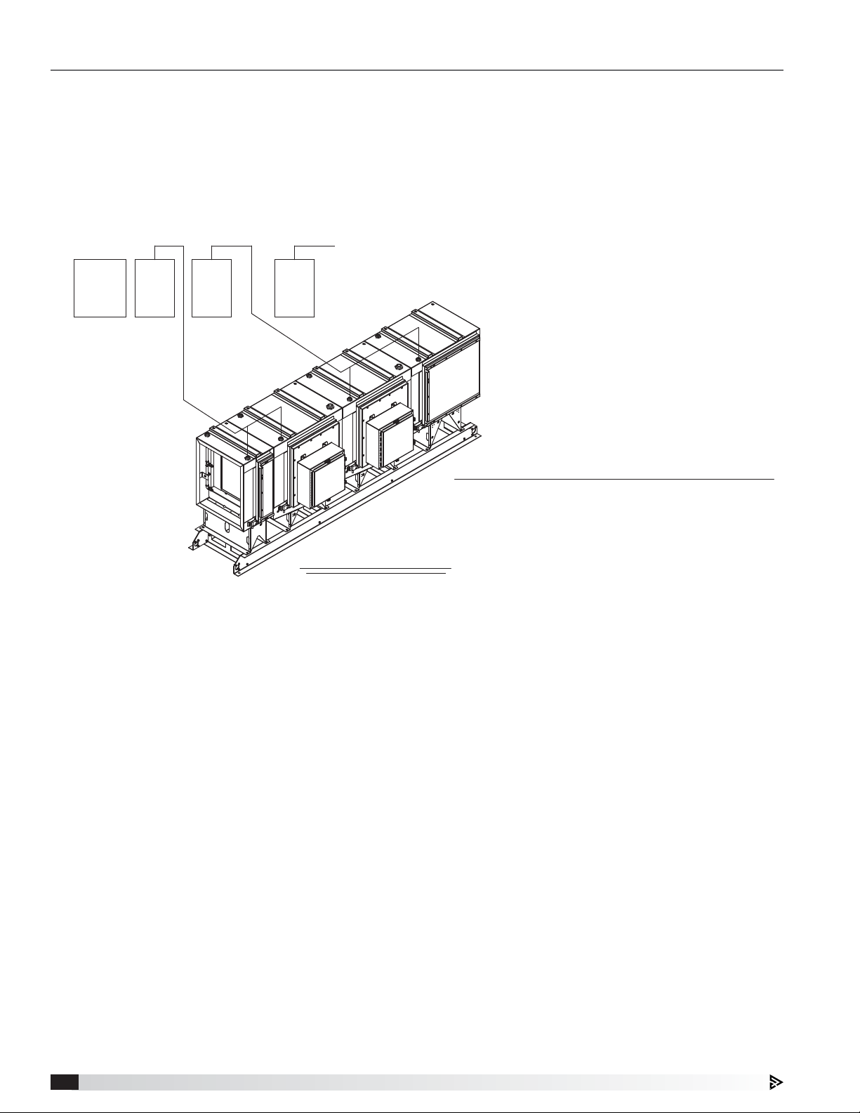
The Grease Trapper ESP™ is a pre-engineered electrostatic precipitator
type pollution control unit with integral exhaust fan (available without
exhaust fan as an option). The unit is designed to remove grease and
smoke particles as well as odor from the kitchen exhaust airstream.
This installation manual covers procedures for receiving, installing, and
maintaining the unit.
For additional instructions and maintenance information on the integral
exhaust fan, when applicable, refer to the fan nameplate to determine
model type and visit accurex.com to download the corresponding manual.
General Safety Information
Only qualified personnel should install this system.
Personnel should have a clear understanding of these
instructions and should be aware of general safety
precautions. Improper installation can result in electric
shock, possible injury due to coming in contact with
moving parts, as well as other potential hazards. Other
considerations may be required if high winds or seismic
activity are present. If more information is needed,
contact a licensed professional engineer before moving
forward.
DANGER
Always disconnect power before working on or near
this equipment. Lock and tag the disconnect switch or
breaker to prevent accidental power up.
CAUTION
To reduce the risk of fire, electric shock, and injury be
sure to follow the cautions below:
• Before servicing, make sure the unit is properly
grounded.
• When servicing the fan, motor may be hot enough
to cause pain or injury. Allow motor to cool before
servicing.
• Do not operate this unit in an explosive atmosphere.
• Keep all flammable materials (such as gasoline)
away from the unit.
• Do not use flammable cleaner on or near the unit.
• The unit should be inspected frequently and the
unit and cells should be manually cleaned at proper
intervals to prevent a fire.
• Operating temperatures of the airstream should not
exceed 130°F.
1. Follow all local electrical and safety codes, as well as
the National Electrical Code (NEC), the National Fire
Protection Agency (NFPA), where applicable. Follow
the Canadian Electrical Code (CEC) in Canada.
2. The rotation of the fan wheel is critical. It must
be free to rotate without striking or rubbing any
stationary objects.
3. Fan motor must be securely and adequately
grounded.
4. Do not spin fan wheel faster than maximum
cataloged fan rpm. Adjustments to fan speed
significantly affects motor load. If the fan RPM is
changed, the motor current should be checked to
make sure it is not exceeding the motor nameplate
amps.
5. Do not allow the wires to kink or come in contact
with oil, grease, hot surfaces or chemicals. Replace
immediately if damaged.
6. Verify that the power source is compatible with the
equipment.
7. Never open access doors to a duct while the fan is
running.
8. The precipitator contains safety electrical interlock
switches at all maintenance access doors. Do not
attempt to defeat these interlocks.
Grease Trapper ESP™ Kitchen Exhaust Pollution Control System 1
Page 2

Receiving
Upon receiving the product, check to make sure all
items are accounted for by referencing items shown
on the packing list. Inspect each crate for shipping
damage before accepting delivery. Notify the carrier if
any damage is noticed. The carrier will make a notation
on the delivery receipt acknowledging any damage
to the product. All damage should be noted on all the
copies of the bill of lading which is countersigned by
the delivering carrier. A Carrier Inspection Report should
be filled out by the carrier upon arrival and filed with
the Traffic Department. If damaged upon arrival, file
claim with carrier. Any physical damage to the unit after
acceptance is not the responsibility of manufacturer.
Unpacking
Verify that all required parts and the correct quantity
of each item have been received. If any items are
missing, report shortages to your local representative to
arrange for obtaining missing parts. Sometimes it is not
possible that all items for the unit be shipped together
due to availability of transportation and truck space.
Confirmation of shipment(s) must be limited to only
items on the packing list. Remove all other shipping/
packing materials including fan tie down straps.
Handling
Units are to be rigged and moved by the lifting brackets
provided or by the skid when a forklift is used. Location
of brackets varies by model and size. Handle in such
a manner as to keep from scratching or chipping the
coating. Damaged finish may reduce ability of unit to
resist corrosion.
Storage
Units are protected against damage during shipment. If
the unit cannot be installed and operated immediately,
precautions need to be taken to prevent deterioration of
the unit during storage. The user assumes responsibility
of the unit and accessories while in storage. The
manufacturer will not be responsible for damage during
storage. These suggestions are provided solely as a
convenience to the user.
INDOOR
The ideal environment for the storage of units and
accessories is indoors, above grade, in a low humidity
atmosphere which is sealed to prevent the entry of
blowing dust, rain, or snow. Temperatures should
be evenly maintained between 30°F (-1°C) and
110°F (43°C) (wide temperature swings may cause
condensation and “sweating” of metal parts). All
accessories (including the main control panel and the
keypad/touchscreen user interface) must be stored
indoors in a clean, dry atmosphere.
Remove any accumulations of dirt, water, ice, or snow
and wipe dry before moving to indoor storage. To avoid
“sweating” of metal parts, allow cold parts to reach
room temperature. To dry parts and packages use a
portable electric heater to get rid of any moisture build
up. Leave coverings loose to permit air circulation and
to allow for periodic inspection.
OUTDOOR
Units designed for outdoor applications may be stored
outdoors, if absolutely necessary. Roads or aisles for
portable cranes and hauling equipment are needed.
The unit should be placed on a level surface to prevent
water from leaking into it. The unit should be elevated
on an adequate number of wooden blocks so that it is
above water and snow levels and has enough blocking
to prevent it from settling into soft ground. Locate parts
far enough apart to permit air circulation, sunlight,
and space for periodic inspection. To minimize water
accumulation, place all unit parts on blocking supports
so that rain water will run off.
Do not cover parts with plastic film or tarps as these
cause condensation of moisture from the air passing
through heating and cooling cycles.
NOTE
The main electrical panel, if stored, shall be stored
indoors only in a dry environment protected from the
elements.
Inspection & Maintenance during Storage
While in storage, inspect equipment once per month.
Keep a record of inspection and maintenance
performed.
If moisture or dirt accumulations are found on parts,
the source should be located and eliminated. At each
inspection, rotate the fan wheel by hand ten to fifteen
revolutions to distribute lubricant on motor. Every three
months, the fan motor should be energized. If paint
deterioration begins, consideration should be given to
touch-up or repainting. Fans with special coatings may
require special techniques for touch-up or repair.
Machined parts coated with rust preventive should be
restored to good condition promptly if signs of rust
occur. Immediately remove the original rust preventive
coating with petroleum solvent and clean with lintfree cloths. Polish any remaining rust from surface
with crocus cloth or fine emery paper and oil. Do not
destroy the continuity of the surfaces. Wipe thoroughly
clean with Tectyl
For hard to reach internal surfaces or for occasional
use, consider using Tectyl® 511M Rust Preventive or
WD-40® or the equivalent.
®
506 (Ashland Inc.) or the equivalent.
Removing from Storage
As units are removed from storage to be installed
in their final location, they should be protected and
maintained in a similar fashion, until the equipment goes
into operation. Prior to installing the unit and system
components, inspect the unit assembly to make sure it
is in working order.
1. Check all fasteners, set screws on the fan, wheel,
bearings, drive, motor base, and accessories for
tightness.
2. Rotate the fan wheel(s), where applicable, by hand
and assure no parts are rubbing.
Grease Trapper ESP™ Kitchen Exhaust Pollution Control System2
Page 3
Table of Contents
Grease Trapper ESP System Function . . . . . . .3
System Components
Unit Body . . . . . . . . . . . . . . . . . . . . . . .4
ESP Cells . . . . . . . . . . . . . . . . . . . . . . .4
Impingement Filters / Mist Eliminator / Filters /
Carbon Trays . . . . . . . . . . . . . . . . . . . . .4
Component Quantities . . . . . . . . . . . . . . . .4
Remote Mounted Detergent Dispenser. . . . . . . .4
Remote Mounted System Control Panel . . . . . . .5
Fire Cabinet . . . . . . . . . . . . . . . . . . . . . .5
PCU Field Assembly
Unit Modules . . . . . . . . . . . . . . . . . . . . .5
Terminal Enclosure . . . . . . . . . . . . . . . . . .6
Attaching Fan . . . . . . . . . . . . . . . . . . . . .6
Installation
Rigging and Placing Equipment . . . . . . . . . . .7
Ductwork Connections . . . . . . . . . . . . . . . .7
Cells and Carbon Trays . . . . . . . . . . . . . . . .7
Plumbing Connections
Detergent Dispenser . . . . . . . . . . . . . . . . .8
Wash Manifolds . . . . . . . . . . . . . . . . . . . .9
Electrical . . . . . . . . . . . . . . . . . . . . . . .9
Fire System
Ansul® . . . . . . . . . . . . . . . . . . . . . . . 10
Initial System Start-Up . . . . . . . . . . . . . . . 11
Sequence of Operation
Normal . . . . . . . . . . . . . . . . . . . . . . . 11
Wash . . . . . . . . . . . . . . . . . . . . . . . . 12
Controller Setup and Tutorial . . . . . . . . . 13-14
A.
B. Input/Output . . . . . . . . . . . . . . . . . 15
C.
D. Manufacturer . . . . . . . . . . . . . . . . 21
Keypad Navigation . . . . . . . . . . . . . . . . . 22
Touch Screen Navigation . . . . . . . . . . . 23-26
Variable Frequency Drive Information . . . . 27-28
BMS Points List . . . . . . . . . . . . . . . . . . . 29
Maintenance . . . . . . . . . . . . . . . . . . 30-31
Unit Layout . . . . . . . . . . . . . . . . . . . . . 31
Field Wiring Diagrams . . . . . . . . . . . . . 32-33
Wash Water Plumbing Schematic
Drain Line Plumbing . . . . . . . . . . . . . . . . 34
Detergent Dispenser Assembly . . . . . . . . . . . 34
Troubleshooting . . . . . . . . . . . . . . . . . . 35
Maintenance Log . . . . . . . . . . . . . .Backcover
Our Commitment . . . . . . . . . . . . . .Backcover
Clock. . . . . . . . . . . . . . . . . . . . . 15
Service. . . . . . . . . . . . . . . . . . 16-21
Grease Trapper ESP
System Function
Grease Trapper ESP is an electrostatic precipitator
pollution control unit (PCU), with an additional carbon
filtration module designed for two specific functions:
• Remove smoke/grease particles from kitchen exhaust
• Remove odor from kitchen exhaust
NOTE
• Grease Trapper ESP must be connected to a listed
exhaust hood assembly and must be installed in
accordance with local building codes, NFPA 96
and NEC.
• The unit must be installed with a minimum 12 inch
clearance to combustible materials on top of unit
and six inches on the sides and bottom.
A mechanical impingement pre-filter removes large
airborne particles from the incoming airstream prior to
reaching the ionizer cell. The permanent electrostatic
collector section removes grease and smoke particles
from the airstream using a high voltage ionizer cell(s).
The ionizer imparts a positive charge on the grease and
smoke particles as they pass. These particles are then
repelled by positively charged plates and collected on
negatively charged plates. Upon completion of each
cooking day, a wash sequence is initiated for the selfcleaning function of the electrostatic cell via the remote
mounted control panel. The mesh mist eliminator filter
prevents wash water from entering the carbon filtration
section(s) of the unit.
NOTE
Do not use this unit for applications with high
concentrations of water vapor, or other matter, that
is highly conductive if condensed in the airstream.
Heavy water vapor can causing continuous electrical
shorting within the ESP cells, which does not allow
the unit to collect cooking particulate and perform
asdesigned.
There are two configuration options for the Grease
Trapper ESP PCU’s. The standard unit will have two
ESP modules and one carbon filtration section for use
with light, medium and heavy duty cooking. For solid
fuel applications which will contain a greater quantity
of grease, smoke and odors, the solid fuel unit should
be selected. The solid fuel unit will contain three ESP
modules and two carbon filtration modules.
NOTE
This unit should NOT be installed in applications
where incoming airstream at the inlet of the unit is
capable of exceeding 130°F.
NOTE
Grease Trapper ESP is designed to remove submicron, airborne particulate generated from cooking
processes. This system is NOT INTENDED to
eliminate regular hood and ductwork cleaning and
service. Improper care and maintenance of this
system and associated hoods and ductwork may
present a fire hazard.
Grease Trapper ESP™ Kitchen Exhaust Pollution Control System 3
Page 4
System Components
NOTE
The installation criteria for each of the system
components shown below should be considered
when selecting a site for install. For further detail on
installing the components, refer to the INSTALLATION
section on page 7.
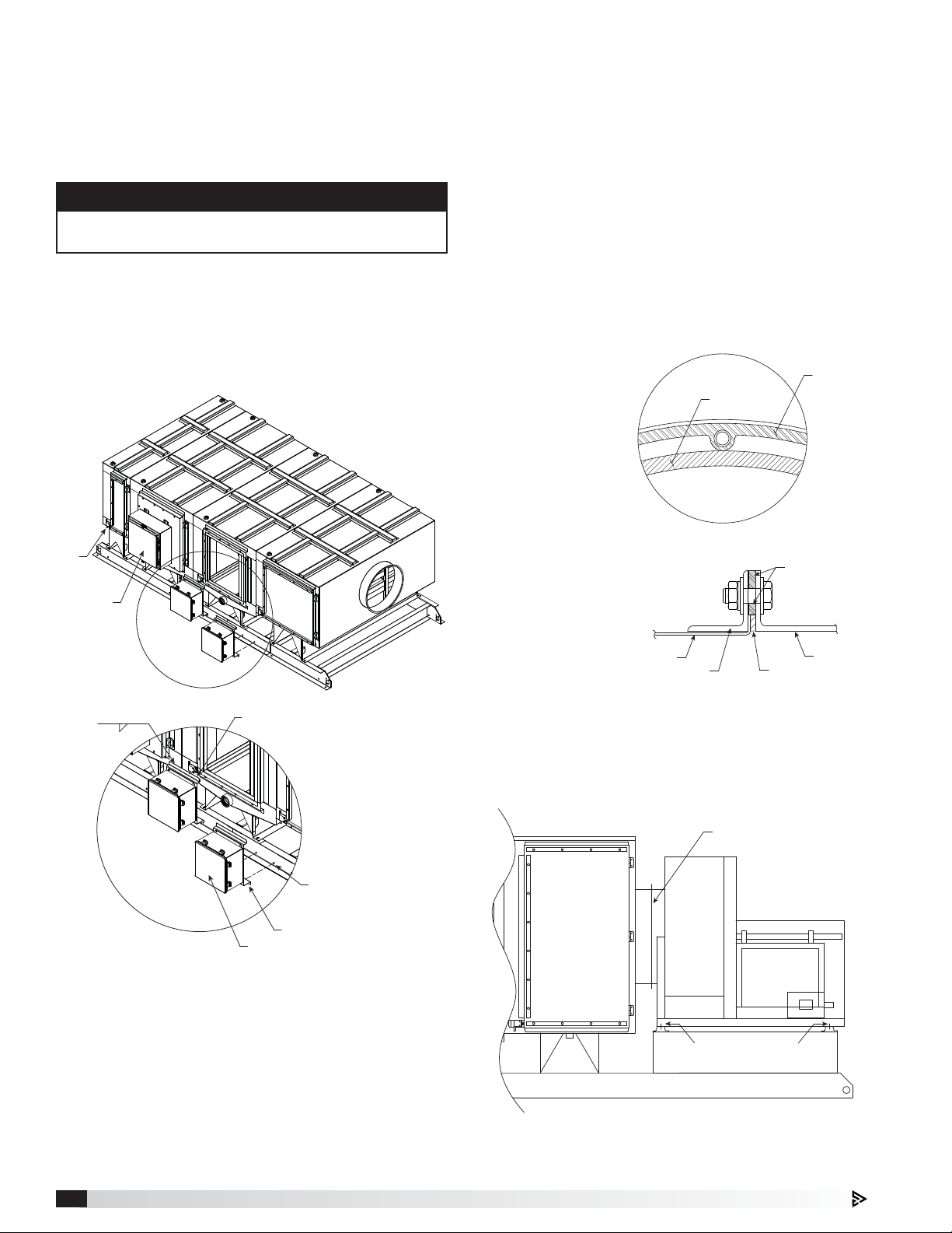
Unit Body
The unit body is shipped on a mounting rails ready for
installation. If the unit was ordered with an exhaust fan,
typically the fan will also be mounted on the same set
of rails as part of the PCU assembly. Unless specified
and built for outdoor use, the PCU must be mounted
indoors and be protected from weather. The unit should
be easily accessible for service personnel. (1) One-inch
water supply line and (1) two-inch waste water drain line
is required at the unit for the system’s wash function.
Power packs (power supply boxes) are attached to
hinged cell access doors of the cabinet assembly which
are wired to the terminal enclosure (disconnect box)
mounted to the rail below. High voltage feed-through
pins safely transfer voltage from power supply to the
cells located inside the unit. Power supplies are selfprotecting against overloads (which can be caused
by contaminant build up that leads to short circuits in
ionizer and collector sections) and are self regulating
from AC input voltage variations from 108 - 264 VAC.
Impingement Filters / Mist Eliminator
Filters / Carbon Trays
Impingement filters and mist eliminator filters will ship
installed in the unit. Carbon trays will ship in a separate
container. Filter quantities for each stage are based on
unit size.
Each carbon filter is a 20 x 20 x 2 inch, 12 lbs, and
contains coconut shell carbon, standard. Max designed
velocity across each filter is 90 ft/min.
Component Quantities
STANDARD UNIT
Housing
Size
15 121 6
30 2 4 2 12
45 3 6 3 18
60 4 8 4 24
90 6 12 6 36
Impingement
Filter
ESP
Cell
Mist Eliminator
Filter
SOLID FUEL UNIT
15 1 3 1 12
30 2 6 2 24
45 3 9 3 36
60 4 12 4 48
90 6 18 6 72
2" Deep
Carbon
Trays
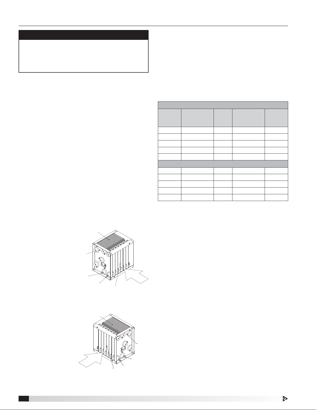
ESP Cells
ESP cells will ship in separate crate to protect them
during shipping. Cell quantities for each stage are based
on unit size.
Cells have an ionizer
section and collector
section. Ionizer section
includes spiked
ionizer plates that are
charged with 12,000
VDC. Collector section
includes alternating
plates between ground
(0 VDC) and 6,000VDC
potential. Cells are fed voltage through high voltage
feed-through pins that are insulated from the unit
housing. These pins
contact brass plungers
located on the side
of the cell near the
bottom. If a module has
multiple cells, power is
passed from cell to cell
through these brass
plungers coming into
contact with the pins on
nextcell.
The total current to both the ionizer section and
collector section is below 6 mA.
Grease Trapper ESP™ Kitchen Exhaust Pollution Control System4
Collector Section
Stamped
Airflow
Direction
Indicator
Collector
Brass Plunger
Ionizer
Brass Plunger
Airflow
Ionizer Section
Left Hand Access Unit Cell
Collector Section
Airflow
Ionizer
Ionizer Section
Brass Plunger
Right Hand Access Unit Cell
Stamped
Airflow
Direction
Indicator
Collector
Brass Plunger
Remote Mounted Detergent Dispenser
A 30 gallon remote mounted detergent dispenser
equipped with 1/2 hp pump is included as part of the
electrostatic collector self-wash system. Solenoid
valves, pressure gauge, ball valve, ystrainer, and
backflow preventer are to be provided by others.
The detergent dispenser must be mounted indoors
on a solid, level foundation, as close to the cabinet
assembly as possible, and in a freeze protected location
accessible to maintenance personnel. The 1/2 inch
line from the detergent dispenser must be connected
to the water supply line prior to the precipitator. Refer
to the PLUMBING section for details on plumbing
connections.
Page 5
System Components - continued
Remote Mounted System Control Panel
The 115 VAC system control panel fed from a 30A
building breaker allows the user to interface with the
unit and controls operation, as well as monitors wash
and other functions. Field wiring connects the system
control panel to the terminal enclosures on the unit,
and works in conjunction with the unit’s power supplies
and high voltage ESP cells. The system control panel
is designed to be mounted indoors (NEMA-1) in an
area easily accessible to daily operational staff. Allow
adequate room from the face of the panels for door
swing clearance and servicing.
Fire Cabinet
The fire cabinet should be mounted as close to the
Pollution Control Unit as possible, typically within 5 feet.
Unless the fire cabinet was provided with an outdoor
cabinet and heater, the cabinet should be mounted
indoors and must be kept above freezing.
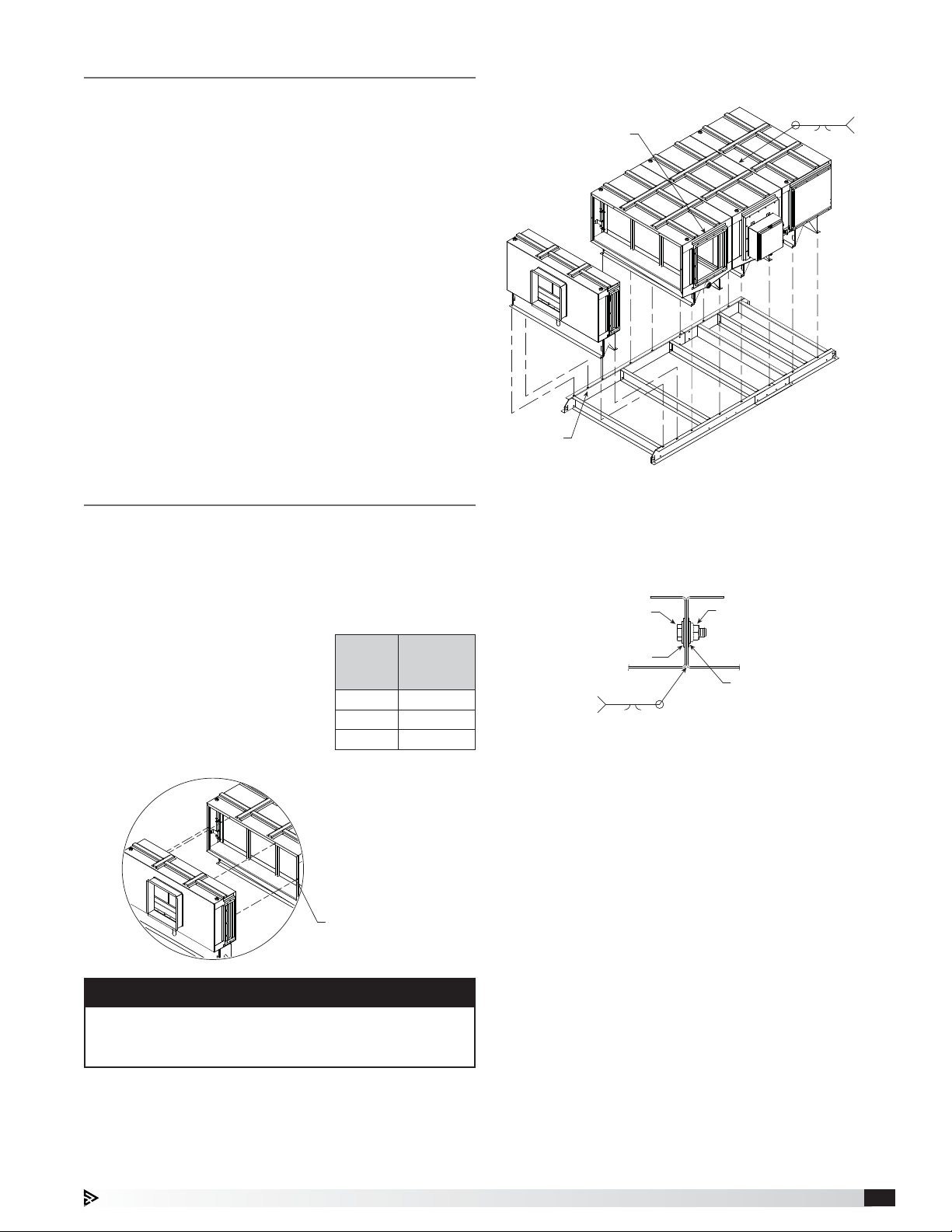
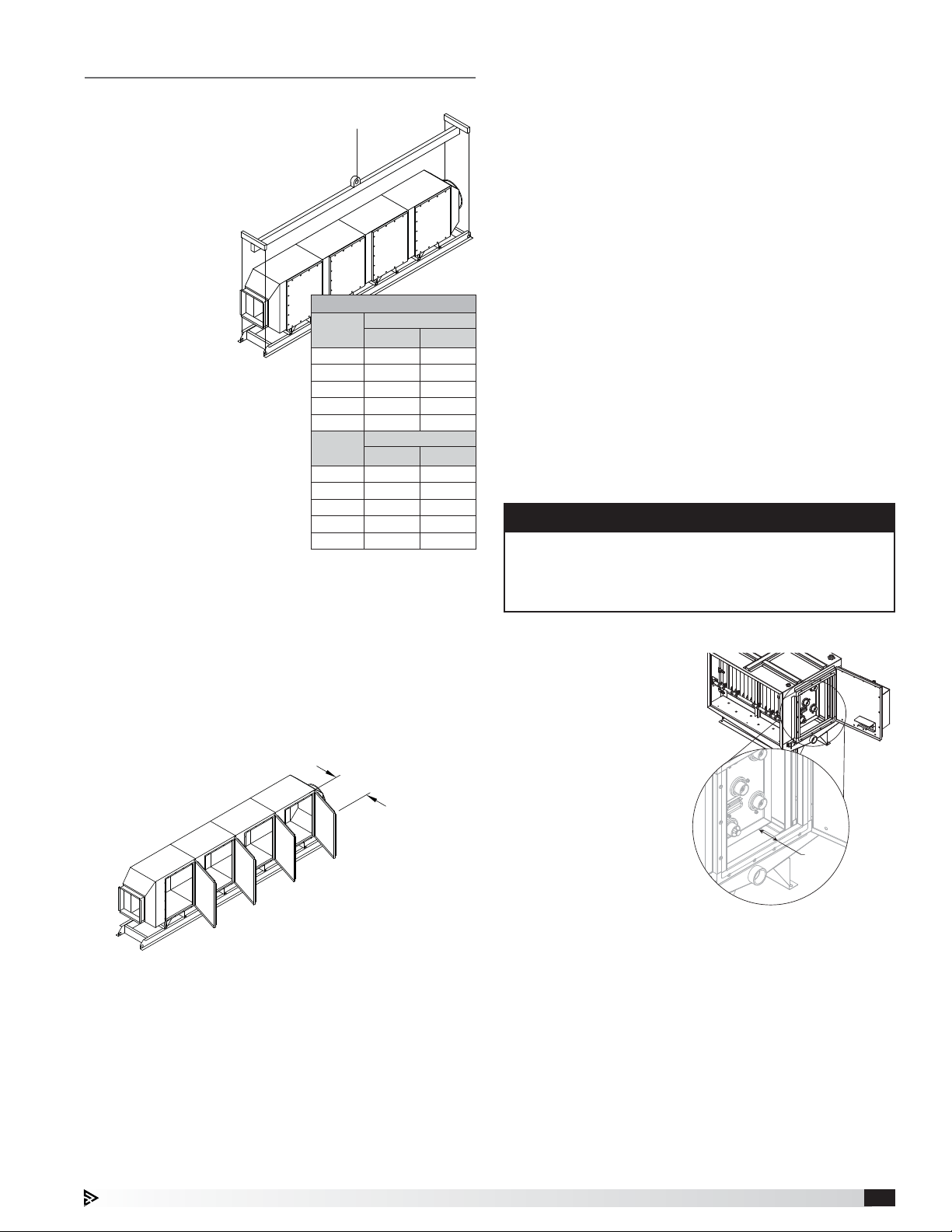
3. After rails and modules have been moved to desired
location, the modules and rails can be reassembled.
Control boxes, access doors, filters,
and ESP cells must be removed
before welding modules together
Each module is
attached to the rails
with (4) 5/16-inch fasteners
1/8
Liquid Tight
PCU Field Assembly - if applicable
If unit is shipped in sections, each section will need to
be welded in the field.
Unit Modules
1. Remove (4) 5/16 inch mechanical fasteners that
attach each module to the rails.
2. Remove 5/16 inch mechanical
fasteners that attach each
module to the next adjacent
module. PCU housing size
can be found in the model
number on tag on side of unit.
Housing
Size
15 3
30, 45 4
60, 90 6
Each module is attached
to the adjacent module
with 5/16-inch fasteners
Number of
Mechanical
Fasteners
4. It is recommended to reattach the fasteners from
step 2 to properly align the modules with each other,
but fasteners are not required when the modules are
welded together from the outside.
INTERIOR OF MODULES
5/16 inch X 1 inch SS bolt
PN# 417205
SS washer with neoprene gasket
Liquid Tight
PN# 417246
1/8
EXTERIOR OF MODULES
5/16 inch SS hex nut
PN# 415576
SS washer with neoprene gasket
PN# 417246
5. Make sure all control boxes, access doors, filters
and cells are removed from the modules before
welding modules together.
6. Fully weld modules together on all four sides on the
outside of the unit. Welds must be liquid tight.
NOTE
Doors will have to be opened and/or removed to
access fasteners inside of modules. A 1/2 inch socket
is required to remove door bolts.
Grease Trapper ESP™ Kitchen Exhaust Pollution Control System 5
Page 6
Terminal Enclosure
1/2 inch silicone gasket
1. The bottom of each terminal enclosure mount needs
to be attached to the rail with (2) 5/16 inch fasteners
(provided by factory).
2. The top of each terminal enclosure mount needs to
be welded to the side of the modules.
NOTE
Be sure terminal enclosures do not block module
drains or doors.
3. Refer to wiring diagram provided with the unit
control panel for more information. Limit switches
(mounted on each module) need to be wired to
terminal enclosures.
4. Plugs on power pack enclosure (ESP modules only)
need to be plugged into the terminal enclosures.
Limit
switch
Power pack
enclosure
1/8 2-3.5
Weld top of terminal enclosure
mount to modules
Attaching Fan
The ESP fan is shipped bolted to unit body and rails. If
the unit was requested to be disassembled in the field,
the unit body-to-fan connection has not been sealed.
1. To disassemble in the field, remove mechanical
fasteners that attach the companion flange and fan
to the unit body.
2. Remove mechanical fasteners that attach the fan to
the isolators on the rails.
After fan and unit body have been moved to desired
location, the fan can be sealed and reattached to
the unit body and rails.
3. To seal the fan to unit body connection, apply fire
rated caulk (3M Fire Barrier Sealant CP25WP+ or
equivalent) to
fan inlet flange.
Make sure to
apply caulk
1/2 inch
silicone gasket
around each bolt
hole. Caulk to be
located outside
of silicon gasket
Seam on gasket to be
located on side of unit
mounted during
step 4.
4. Attach 1/2 inch silicone gasket around fan inlet
flange. Silicone gasket
to be located inside
of caulk applied
in step 3 (seam
of gasket to be
located on the
side of unit).
Transition collar
Companion flange
5. To reassemble locate fan on isolators on rails.
6. Reattach fasteners for companion flange removed in
step 1.
7. Reattach fasteners attaching fan to isolators
removed in step 2.
Liberally apply
fire caulk to
outside portion
of companion
flange and
around each
individual
bolt hole
Fire rated caulk
Fan
Fasteners attaching fan to ESP
transition are evenly spaced
around fan inlet
Connect bottom of terminal
mounting bracket to rails with
(2) 5/16 inch fasteners each
(provided by others)
Terminal enclosure mount
Terminal enclosure
Fasteners attach the fan to
the isolators on each corner
of the fan
Grease Trapper ESP™ Kitchen Exhaust Pollution Control System6
Page 7
Installation
4 inches
Rigging and Placing Equipment
1. The unit is furnished with lifting lugs
at the four corners. For corner
weights, reference the unit’s
submittal drawings.
2. Use a crane and a
set of spreader
bars hooked to
all four factory
lifting lugs to lift
the unit.
3. Field weight will
vary depending
upon final
selections
such as fan
type, accessories, etc.
Approximate weights are
shown in the table.
4. The unit can be positioned
on a base or roof deck
suitable for this purpose.
5. The unit must be anchored
to its base/roof deck.
6. Alternatively, the unit may be suspended from
an adequate overhead structure, using suitable
undercarriage or hanging rods (by others). If
suspended a cradle or support structure must be
provided by others to support unit from bottom. All
hanger brackets/lifting lugs must be used to ensure
proper support. The unit must also be hung level to
ensure proper operation.
7. A service clearance of 36 inches must be provided
on the access door side of the unit.
8. A minimum 12inch clearance must be maintained
between the top and 6 inches on each side and
bottom of this unit and any combustible material.
Approximate Weight
Housing
Housing
STANDARD UNIT
Size
15 1410 641
30 1710 777
45 2120 964
60 2765 1257
90 3315 1507
Size
15 1860 845
30 2295 1043
45 2860 1300
60 3660 1664
90 4390 1995
36 inches
lbs kg
SOLID FUEL UNIT
lbs kg
Ductwork Connections
Ductwork must conform to IMC and SMACNA guidelines.
All factory-built grease duct needs to be constructed
in accordance with ANSI/UL 1978 and should be
manufactured and installed in accordance with their
listing.
All field-built grease ductwork must be constructed in
the following manner per NFPA 96, unless otherwise
specified by the local authority having jurisdiction (AHJ):
Materials - Ducts shall be constructed of and supported
by carbon steel not less than 1.37 mm (0.054 in.) (No.
16 MSG) in thickness or stainless steel not less than
1.09mm (0.043 in.) (No. 18 MSG) in thickness.
Installation - All seams, joints, penetrations, and duct-
to-hood collar connections shall have a liquid-tight
external weld.
Units intended for indoor mounting have an outlet
mounting flange provided on the outlet of the fan. Outlet
ductwork from the exhaust fan is required to be per the
above mentioned methods unless otherwise specified by
the local authority having jurisdiction (AHJ).
NOTE
Ductwork should be properly insulated to prevent
formation of condensation through temperature
change. Condensation that occurs in ductwork will
short circuit ionizing-collecting cells.
Cells and Carbon Trays
Open ESP cell and carbon
tray access doors using
1/2inch socket wrench to
remove all bolts.
Insert cells into the ESP
module(s) in the unit,
making sure the brass
plungers are on the
bottom facing towards
you and the airflow arrow
stamped on each cell is
pointing towards the fan.
ESP cells should be pushed
in by the one next in the row.
For example, the second cell pushes the first cell,
third cell pushes the second, etc. The last cell installed
should be no more than 4 inches (±1/8inch) from the
edge of the cell to the edge of the frame.
Insert carbon trays into the carbon module(s) in the unit.
Make sure trays are inserted where gasketing material is
orientated on the left and right hand side, NOT the top
and bottom, so there is a seal against the filter next to
them.
After all cells and filters are properly installed, refasten
unit doors. Torque the bolts to 60-70 in-lbs. Bolts should
be started by hand prior to using an impact driver or
socket.
Grease Trapper ESP™ Kitchen Exhaust Pollution Control System 7
Page 8
Plumbing Connections
NOTE
All water piping exposed to freezing temperatures
must be trace heated and insulated to prevent
damage to the unit.
Once all system components are installed, plumbing
connections for the system can be made. It is
recommended that plumbing connections be done prior
to making electrical connections.
From the building, a 1-inch (refer to drawings) hot
water line is required for connecting the wash system.
Recommended water temperature is 140-180°F at 40
psi pressure. Make sure water pressure does not exceed
50 psi. Refer to the chart for information on water and
detergent quantity requirements. Install the quarter
turn ball valve (by others) at the incoming water source
to allow the water to be turned off for servicing. Next,
install the strainer (by others), backflow preventer (by
others), pressure gauge (by others), and 24 VAC solenoid
valve (by others) respectively. Locate these items along
the incoming water line in a location convenient for
inspection/servicing.
Approximate Water and Detergent Used per Wash Cycle (gallons)*
Housing
Size
15 70 1 105 2
30 140 1 210 2
45 210 2 315 4
60 220 2 330 4
90 330 2 495 4
Water usage numbers shown above are assuming factory default
wash cycle times. Actual water and detergent required may be
different based on the cooking load, appliance type, and cooking
frequency/time.
*Assuming 40 psi water pressure
STANDARD UNIT SOLID FUEL UNIT
Water Detergent Water Detergent
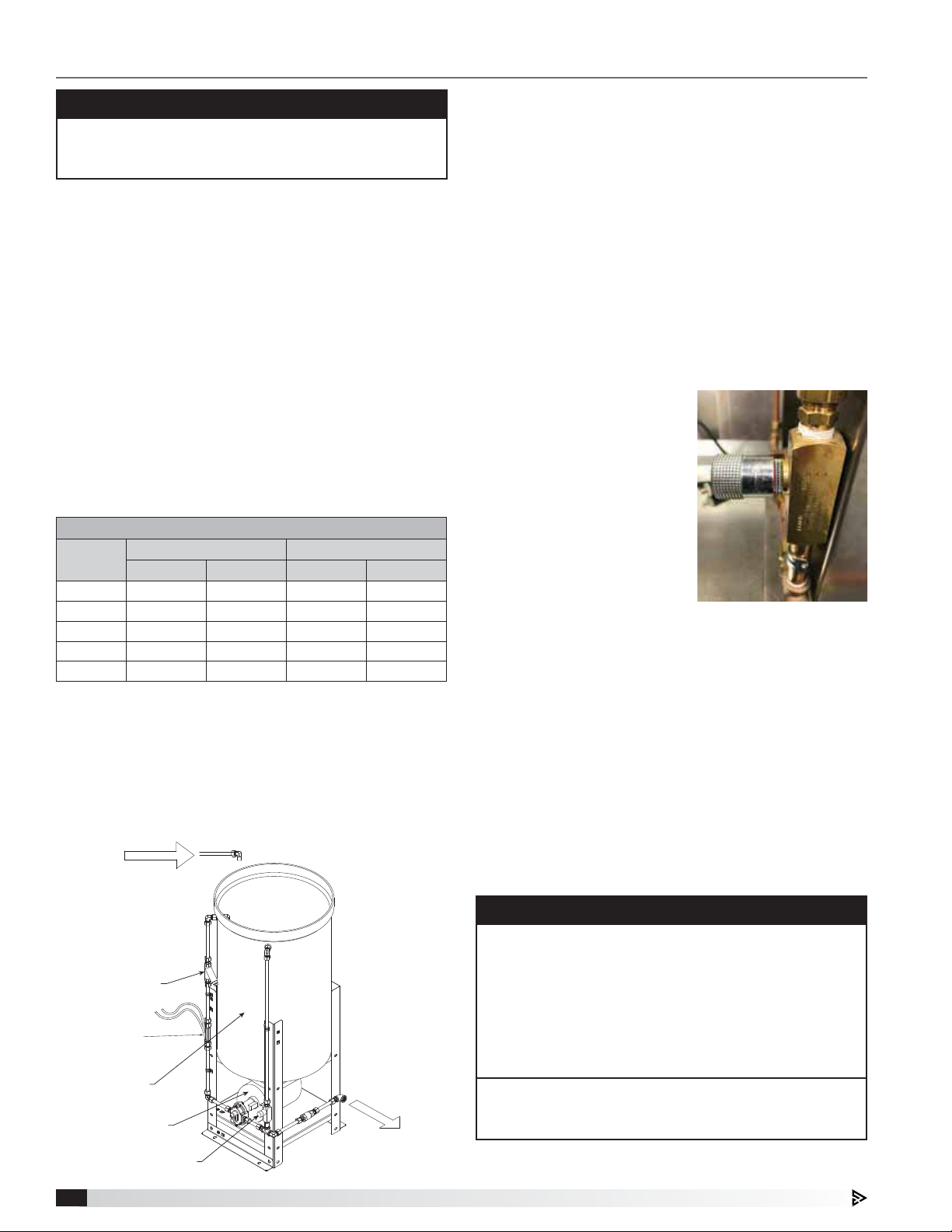
Detergent Dispenser
The detergent dispenser supplies detergent to the wash
system during the WASH mode.
1/2-inch
Hot Water
Fill Line
(Recommended
To Make It
Easier For
Detergent
Dillution)
Y-strainer
With Sediment Trap
Detergent
Flow Switch
Detergent Tank
Detergent Pump
1/2-inch
Detergent
Injection
Line (Connect
To 1-inch
Water Line)
When the unit is washing and the wash sequence is
calling for detergent, a pump housed underneath the
detergent tank pumps the detergent into the hot water
line. A Y-strainer is responsible for removing debris
and sediment from reaching the pump. A flow switch
determines if detergent is flowing when detergent is
being injected (if the flow switch doesn't close within
a time period upon detergent pump running, this will
trigger a low detergent fault). A detergent flow valve is
responsible for diverting some detergent back into the
tank. Turning the flow valve knob clockwise (closing
the valve) will force more detergent into the hot water
line and to the unit during a wash. Turning the flow
valve knob counter-clockwise (opening the valve) will
force more detergent back into the tank during a wash.
A series of colored rings on the flow control valve
indicate how opened/closed
the valve currently is. This can
be adjusted as needed based
on the detergent required for
the wash cycle, but should
start with setting the valve so
that the red ring is visible,
(see Flow Valve image) which
should equate to roughly
0.6GPM. Adjustments to the
flow control setting should be
done in small increments over
a period of several wash cycles.
Flow Valve
This flow valve may be locked into place by a black
hex head set screw located on the bottom of the flow
valve, just below the adjustable knob. Loosen the set
screw before making an adjustment using a 2-mm
Allenwrench.
From the pump located on the base of the detergent
dispenser, connect a 1/2-inch piping connection for
the detergent supply to the 1-inch water supply line.
A quarter turn ball valve (by others) can be installed
on this line if necessary for servicing. The connection
of the 1/2-inch detergent supply line to the 1-inch
water supply line should be made within 10 feet of the
cabinetassembly.
NOTE
Upon the system detecting no detergent flow for
the detergent alarm delay time, the system will go
into a low detergent alarm and the detergent pump
will be immediately shut off. The low detergent fault
can be manually reset (see page 14 for details), or it
will automatically reset if detergent flow is detected
upon the next wash cycle when detergent injection is
takingplace.
Pump should be located as close to unit as possible,
on same floor. Maximum distance recommended from
detergent pump to unit is 10 feet.
Detergent Flow Valve
Grease Trapper ESP™ Kitchen Exhaust Pollution Control System8
Page 9
Plumbing Connections - continued
Electrical
Wash Manifolds
The unit is supplied with 1-inch wash headers located
at the top of each ESP module. Connect the hot water
supply line to the wash headers at the top of the
ESP module. Bring a 2-inch waste water drain piping
connection with P trap to the drain pipe on the side of
the ESP module. The trap drain line water column for
the drain should be sized for the total system resistance
plus 1 in. wg.
For more information, refer to the plumbing schematic
located on page 34.
The Grease Trapper ESP PCU will be supplied with
a detergent tank and pump and connection headers
on each module. All other plumbing components and
piping will be provided by others. Follow all applicable
plumbing codes and best practices when installing
system.
Required Plumbing Components
(Provided by Others)
Quantity Item Description
3 Ball Valve
1 Y Strainer
2 Backflow Preventer or Check Valve
1 Pressure Gauge
4 24 VAC Solenoid Valves - Standard Unit
5 24 VAC Solenoid Valves - Solid Fuel Unit
Once all system components are installed, electrical
connections for the system can be made. It is
recommended that plumbing connections be done prior
to making electrical connections.
CAUTION
RISK OF ELECTRIC SHOCK. All wiring to be done by
qualified personnel only.
NOTE
All wiring must be done according to the equipment
data plate information, NEC (National Electrical Code
NFPA 70), and local codes.
NOTE
All wiring must be permanently installed in conduit.
Under no circumstances should extension cords be
used to connect the source of electrical supply to the
equipment.
NOTE
An earth ground must be provided to the unit
assembly housing and main control panel. If shipped
loose for remote mounting, terminal enclosures must
be provided with earth ground. The detergent pump
motor and solenoid valve must also be appropriately
grounded.
The Grease Trapper ESP PCU will require additional field
wiring for proper installation. The main control panel
will be shipped loose and is designed to be mounted
indoors. A typical field wiring diagram is shown on page
32. Refer to the unit specific wiring diagram located on
the inside of the door of the system control panel for
unit specific wiring that is required.
Grease Trapper ESP™ Kitchen Exhaust Pollution Control System 9
Page 10
Fire System
The Pollution Control Unit (PCU) is furnished with factory pre-piped fire suppression nozzles. Field connection, tanks,
controls, fusible link detectors, and commissioning is provided and installed, based on specifications at time of
order. The Authority Having Jurisdiction (AHJ) may require additional protection.
The fire system must be installed and operational to maintain the UL Listing of the unit. Refer to the drawings below
for information on field piping the fire system to the unit. The release and tanks should be mounted no more than
5feet away from the PCU unit.
ANSUL
To duct nozzles
(duct nozzles by Distributor)
RELEASE
TANK TANK TANK
FIRE SYSTEM DISTRIBUTOR / FIRE SYSTEM INSTALLER:
There are two quik-seals on each module. Connection to
only one of the quik-seals on each module is required.
Multiple quik-seals are provided for situations where
there are obstructions to the connection point.
TYPICAL DRAWING
• Do not install fire piping in front of doors on module. Must have 36 inches of clearance.
Grease Trapper ESP™ Kitchen Exhaust Pollution Control System10
Page 11
Initial System Start-Up
1. Verify unit is installed properly and all field water
and electrical connections have been made.
2. Check that all ESP cells have been installed
properly. There is a directional arrow that indicates
the direction of the proper airflow. If cells are not
installed in the proper direction, the unit will not
operate correctly.
3. Close and properly fasten the doors on the unit to
ensure the door limit switches are closed.
4. Turn on electrical power to control cabinet and
exhaust fan.
5. Turn on fan disconnect.
6. Turn on the disconnect switch on the PCU terminal
enclosures to energize the power packs.
7. Press the fan button on the user interface to start
the fan. The green indicator lights on the terminal
enclosure(s) should illuminate indicating the power
supply is powering cells. Some electrical arcing
(audible snapping and cracking) is normal at
initial power up as leftover debris in the duct and
unit may occasionally get caught inside the cells.
When the ionizer section on an ESP cell is arcing,
the green indicator light on the terminal box will
shut off, and the red indicator light will illuminate
temporarily. When the collector section of an
ESP cell is arcing, the green indicator light on the
terminal box will shut off, and both the red and
green indicator lights will remain off temporarily.
Arcing should subside after a short period of
time. If arcing continues, reference page 35 for
troubleshooting assistance.
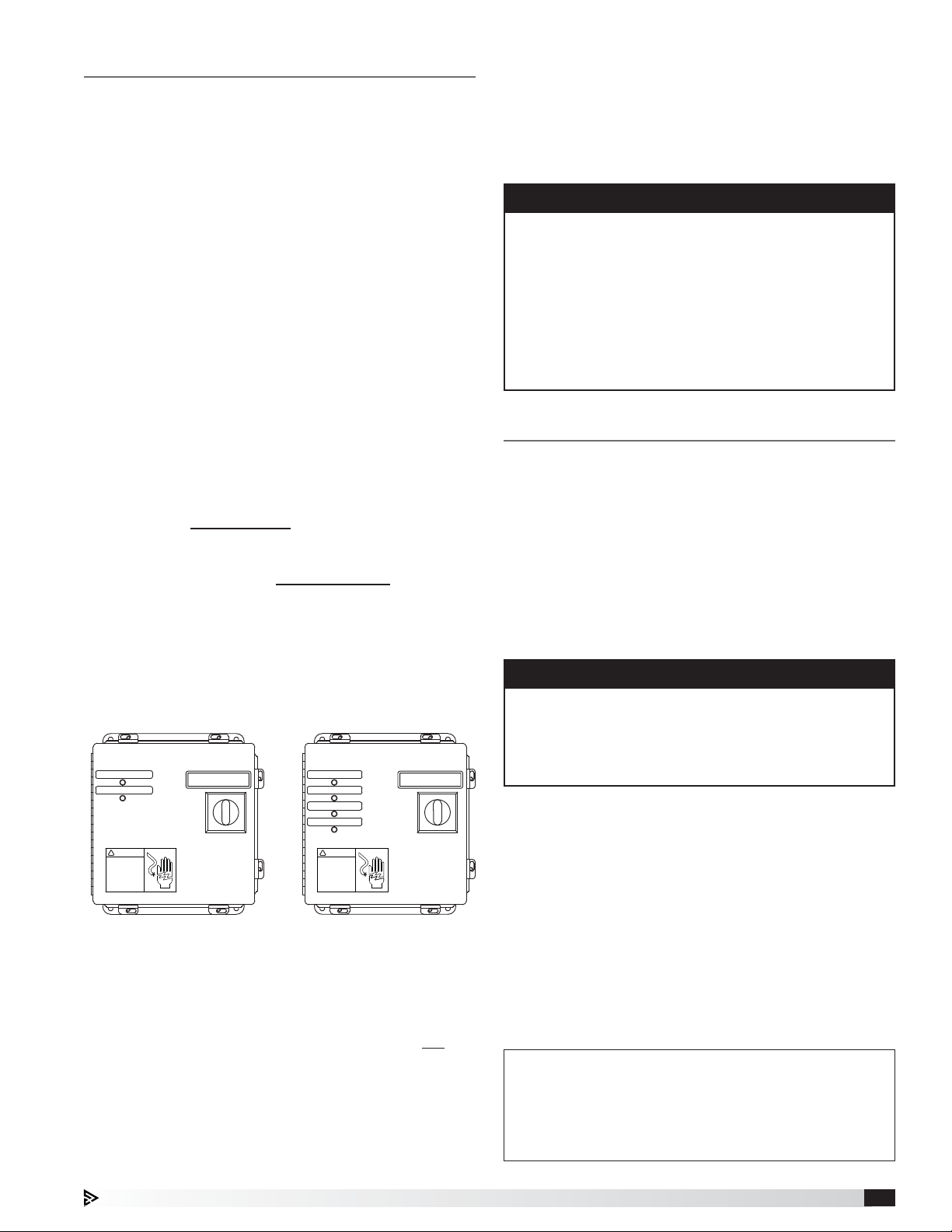
POWER SUPPLY OFF/FAULT
POWER SUPPLY ON
!
DANGER
High
Voltage
Housing Size
15, 30, 45
DO NOT REMOVE THIS PANEL
Unless electrical switch is in the OFF position.
Failure to do so will damage switch.
ON
OFF
POWER SUPPLY OFF/FAULT
POWER SUPPLY ON
POWER SUPPLY OFF/FAULT
POWER SUPPLY ON
!
DANGER
High
Voltage
Housing Size
60, 90
DO NOT REMOVE THIS PANEL
Unless electrical switch is in the OFF position.
Failure to do so will damage switch.
ON
OFF
• RED indicates an ionizer fault within a cell
• GREEN indicates normal operation
• NO LIGHTS indicates power supply is off OR
collector fault within a cell
8. The indicating lights on the terminal enclosure(s)
will indicate status of the power supplies. Terminal
enclosure indicator lights will remain off unless fan
is running.
9. Check for alarms on the system controller. Correct
any alarms that may be displayed (See page 14
fordetails).
10. System should now be ready for operation.
NOTE
As a safety precaution, the system will only operate
in the NORMAL mode when the access doors of
the unit are completely closed and the terminal box
disconnect switch is in the ON position.
If the plunger of the safety switch on all of the doors
is not fully depressed, the red FAULT light on the
main controller (PLC) will illuminate and the unit will
not start. Do not attempt to operate the unit with the
access doors open or bypass the safety.
Sequence of Operation
The operation of the Grease Trapper ESP system falls
into two main categories:
1. NORMAL: System collects smoke and grease
particulate from the airstream.
The unit can be started by pressing the fan button on
the user interface or by closing the remote run contact
(terminals RE-1A and RE-1B). The remote run command
is a contact that can be wired to the kitchen control
panel, timeclock, or any other contact closure desired to
call for the system to run.
NOTE
BOTH the keypad fan button needs to be disengaged
AND the remote run contact needs to be open in
order for the fan to shut off. A call for the fan to run
will not allow for a wash to start, which will prevent
the cells from being cleaned.
During normal operation, as the grease enters the
unit, it will pass through an impingement filter that is
designed to remove the large grease particles. After
passing through the impingement filter, it will enter the
ESP module(s) which will remove the grease particles
and smoke from the airstream through a process
of electrostatic precipitation. Upon leaving the ESP
modules, the air then passes through a mist eliminator
filter which stops water from entering the carbon filters
during the wash down process and also helps protect
the carbon filter section from grease build-up. The air
then enters the carbon filtration section which removes
the odors from the airstream.
Normal Mode
• Exhaust Fan - Running
• Terminal Enclosure Indicator Lights - Green
• Main Solenoid Valve - Closed
• Detergent Pump - Off
Grease Trapper ESP™ Kitchen Exhaust Pollution Control System 11
Page 12

Sequence of Operation - continued
2. WASH: System goes through cycles to clean and
dry dirty ionizing-collecting cells
The wash cycle is recommended to be performed
daily on the unit and uses an automated wash down
sequence to remove the grease that has been collected
on the ESP cells. The length of time and frequency of
washing will be determined by the grease load in the
airstream. The times shown are the factory settings but
can be adjusted as needed based on site conditions.
The wash cycle can be started three different ways:
1. User presses the wash button on the keypad or
touch screen.
2. An external wash contact is closed (terminals WS-1A
and WS-1B).
3. The controller can be set up to wash the unit
automatically based on a schedule set up on the
controller.
The wash sequence will wash each ESP module using
the steps below. For units with multiple ESP modules,
the wash sequence will repeat itself for each module
with the exception of the drip dry and fan dry sequence.
The drip dry and fan dry portion will start once all of the
modules have completed washing and are used to dry
the entire unit before placing it back into service.
Wash Override: The wash sequence can be stopped
by pressing the wash button on the user interface. This
will cancel the wash sequence and return the PCU to
normal operation. When calling for a wash or during the
wash sequence if the fan is turned on either by the fan
button, remote fan enable contact, or the fire system is
activated the wash sequence will stop and the exhaust
fan will turn on.
Pre-Soak
• Exhaust Fan - Off
• Terminal Box Indicator Lights - Off
• Main and ESP Module Solenoid Valve - Open
• Detergent Pump - Off
• Time - 3 minutes
Detergent
• Exhaust Fan - Off
• Terminal Box Indicator Lights - Off
• Main and ESP Module Solenoid Valve - Open
• Detergent Pump - On
• Time - 30 seconds (Housing sizes 15 and 30)
1 minute (Housing sizes 45, 60 and 90)
Rinse
• Exhaust Fan - Off
• Terminal Box Indicator Lights - Off
• Main and ESP Module Solenoid Valve - Open
• Detergent Pump - Off
• Time - 4 minutes
Detergent
• Exhaust Fan - Off
• Terminal Box Indicator Lights - Off
• Main and ESP Module Solenoid Valve - Open
• Detergent Pump - On
• Time - 30 seconds (Housing sizes 15 and 30)
1 minute (Housing sizes 45, 60 and 90)
Soak
• Exhaust Fan - Off
• Terminal Box Indicator Lights - Off
• Main and ESP Module Solenoid Valve - Closed
• Detergent Pump - Off
• Time - 3 minutes
Rinse
• Exhaust Fan - Off
• Terminal Box Indicator Lights - Off
• Main and ESP Module Solenoid Valve - Open
• Detergent Pump - Off
• Time - 4 minutes
Drip Dry
• Exhaust Fan - Off
• Terminal Box Indicator Lights - Off
• ESP Module Solenoid Valve - Closed
• Detergent Pump - Off
• Time - 1 minute
Fan Dry
• Exhaust Fan - On
• Terminal Box Indicator Lights - Off
• ESP Module Solenoid Valve - Closed
• Detergent Pump - Off
• Time - 90 minutes
Soak
• Exhaust Fan - Off
• Terminal Box Indicator Lights - Off
• Main and ESP Module Solenoid Valve - Off
• Detergent Pump - Off
• Time - 3 minutes
Grease Trapper ESP™ Kitchen Exhaust Pollution Control System12
Page 13

Controller Setup and Tutorial
The user can access the main menu by pressing the
button.
Within the programmable logic controller, factory set
points can be modified to configure the system for
specific functions if necessary. All parameters are
shown in this section.
Some of the menus require the user to enter a password
in order to enter the menu. The service password is
1000 and is entered by pressing the
number and to advance the cursor, press the button.
Escape Allows the user to exit the current menu, jumping to the Main Menu.
to change the
Keypad Navigation
The DDC controller is located in the unit control panel.
The face of the controller has six buttons, allowing the
user to view unit conditions and alter parameters. The
DDC controller is pre-programmed with easy to use
menus.
!
Ì
To change the display contrast, hold the Alarm
Program
and arrows.
If equipped, the keypad user interface connects via a
factory-provided RJ-25 cable to the J10 port on the
controller.
Information regarding most of the settings within the
Controller U1 are provided in this Installation, Operation
and Maintenance Manual.
buttons simultaneously while pressing the
and
Up | Down
!
Ì
Exhaust 1 Setpoints
Temp Speed
Low: 90.0°F 50.0%
High: 115.0°F 100.0%
Current Temp: 70.0°F
Exhaust 1 Setpoints
Temp Speed
Low: 90.0°F 50.0%
High: 115.0°F 100.0%
Current Temp: 70.0°F
Alarm
Enter
Program Pressing the Program button allows the user to enter the Main Program Menu.
The arrow buttons allow the user to scroll through different screens and adjust
parameters.
Button will blink red, indicating an alarm condition. Press to review current alarms. To
review previous alarms, access the DATA LOGGER in the alarm menu.
A. In screens with adjustable parameters, pressing the Enter button moves the cursor
from the upper left corner of the screen to the parameter. The arrow buttons can then
be used to adjust the parameter.
B. To move to the next parameter on the same screen, press the Enter button.
C. To save the change, press the Enter button until the cursor moves back to the upper
left corner of the screen.
Example of Parameter Adjustment
Once you enter into a menu that has adjustable parameters, the cursor always
begins in the upper left corner of the display and will be blinking. Press the
button to move the cursor down for parameter adjustment.
Once the cursor has reached the desired parameter, press the buttons to
adjust the value.
Exhaust 1 Setpoints
Temp Speed
Low: 90.0°F 50.0%
High: 115.0°F 100.0%
Current Temp: 70.0°F
When satisfied with the adjustment, press the button to save the parameter.
When finished, make certain the cursor is in the upper left corner. If the
cursor is not in the upper left corner, the changes will not be saved. The
cursor must be in the upper left corner to enable screen advancement.
Grease Trapper ESP™ Kitchen Exhaust Pollution Control System 13
Page 14

Main Menu Overview
If the PCU panel is configured with a touch screen, the controller will revert back to a PCU status loop. This loop
includes several screens to view the operating conditions of the unit. If configured, scroll through the menu screens
by using
appear for every system.
buttons. Screens with a dashed line border are dependent upon the configuration and may not
PCU Exhaust Fan
Exhaust: On
Speed: XXX%
System Status:
***
!
button will flash red on the controller and the keypad (if connected).
Ì
Ì
If an alarm occurs, the
Alarms
Press DOWN to review current
alarm(s).
Press ESC to exit.
Press ALARM to reset.
ALARM
***
Exhaust Fan Alarm
Check exhaust fan starter
No active alarm
Press ENTER key
to access ALARM
HISTORY log.
or VFD.
Alarms
PCU STATUS :
This screen will display the status of the PCU exhaust fan as well as display fan
speed.
Example of Alarms
To navigate to the alarm menu, press the
scroll through any current alarms. Once the problem causing the alarm has been
corrected, all alarms except low detergent will automatically clear. Pressing the
!
button will clear the low detergent fault if it needs to be manually cleared. If the
alarm cannot be cleared, the cause of the alarm has not been fixed.
This is an example of an exhaust fan fault.
This screen appears if there are no active alarms.
To view all saved alarms, press the button to enter the DATA LOGGER. For
more information, see the Data Logger menu.
!
button once. Press the
Ì
button to
Alarm Alarm Description
Low Detergent No detergent flow or empty detergent tank*
Fan Fault Failure of the exhaust fan
PCU Door Fault One of the doors to the unit is open
Power Supply Failure Power supply has failed
Fire Detected Indicates fire in either the kitchen or PCU unit
*Depending on the software version for the controller provided with your specific system, the low detergent
alarm may have to be cleared manually. If your system requires you to clear the fault manually, fill the
detergent tank with the 1:1 detergent/water mix, then clear the alarm from the system from the user interface.
If your system automatically clears low detergent faults, fill the detergent tank with 1:1 detergent/water mix,
and the fault will be cleared upon the next wash cycle.
Grease Trapper ESP™ Kitchen Exhaust Pollution Control System14
Page 15

A. Clock
The Clock menu allows the user to view and alter the time and date. The user can
also adjust the daylight savings time setting.
Clock
02:00:00PM 01/01/18
Date: MM/DD/YY
Hour: 15:30
Day: Monday
Clock
DST: Enable
Transition time: 60min
Start: LAST SUNDAY
in MARCH at 2.00
End: LAST SUNDAY
in OCTOBER at 3.00
Holiday Configuration
Number: 4
Wash and fan schedules will
not operate during holidays.
Holiday X
1: 0/ 0 - 0/ 0
2: 0/ 0 - 0/ 0
3: 0/ 0 - 0/ 0
4: 0/ 0 - 0/ 0
THE CLOCK SCREEN ALLOWS THE USER TO ADJUST THE TIME AND DATE.
The time/date will not be adjustable on the controller if the user interface is the
touch screen.
THIS SCREEN ALLOWS THE USER TO ADJUST DAYLIGHT SAVINGS TIME SETTING.
The Daylight Savings time feature can be adjusted to meet the current daylight
savings time requirements.
THIS SCREEN ALLOWS THE USER TO ADD AND ADJUST HOLIDAY TIMES.
The user can add up to 16 holidays. Adding holidays will prevent the wash and fan
scheduler controlling the wash/fan during the days selected.
B. Input/Output
Analog Input
Fan Speed (AIN1)
Input Ch: B001 0.0%
Digital Input
On / Off (DIN1)
DI 1 Status: Open
Relay Output
Exhaust Relay (DOUT1)
Relay 1 Status: OFF
Analog Output
Fan Speed (AOUT1)
Output: 5.00vdc
The Input/Output menu allows the user to quickly view the status of the controller
inputs and outputs.
To manually control I/O values, go to the Service menu > Service settings >
I/O Manual Control.
Similar screens appear for all controller inputs and outputs.
Your controller may not utilize the input shown. See unit wiring diagram for your
specific configuration.
Similar screens appear for all controller inputs and outputs.
Your controller may not utilize the input shown. See unit wiring diagram for your
specific configuration.
Similar screens appear for all controller inputs and outputs.
Your controller may not utilize the output shown. See unit wiring diagram for your
specific configuration.
Similar screens appear for all controller inputs and outputs.
Your controller may not utilize the output shown. See unit wiring diagram for your
specific configuration.
Grease Trapper ESP™ Kitchen Exhaust Pollution Control System 15
Page 16

C. Service
The Service menu allows the user to access several sub-menus regarding controller
information, controller overrides, operating hours, BMS configuration, I/O manual
management and wash settings. By accessing the BMS Configuration sub-menu,
the user can adjust BMS protocol settings. (BACnet®, LonWorks®, Modbus)
C. Service
a. System Information
Information
Accurex, LLC.
Version: 1.0.006
Date 07/19/19
Bios: 6.27 09/07/04
Boot: 5.00 09/07/04
C. Service
b. Power Supply
Power Supply Settings 1
Power Supply Operating
Signal Voltage
Pass1: 3.0vdc (12.0kV)
Pass2: 3.0vdc (12.0kV)
Pass3: 3.0vdc (12.0kV)
Power Supply Settings 2
Power supply initial reset
attempts before alarm: 10
The System Information sub-menu displays information about the controller and
the program loaded on the controller.
THIS SCREEN SHOWS VERSION, BOOT AND BIOS INFORMATION. BIOS AND BOOT PERTAIN
TO THE CONTROLLER’S FIRMWARE AND OPERATING SYSTEM.
The Power Supply sub-menu allows the user to view and adjust the power supply
settings.
THIS SCREEN ALLOWS THE USER TO ADJUST OUTPUT SIGNAL POWER TO THE POWER
SUPPLIES AND THE CORRESPONDING KV OUTPUT.
This should only be adjusted on factory advisement only. Default is 3.0vdc (12kV).
THIS SCREEN ALLOWS THE USER TO ADJUST POWER SUPPLY RESET ATTE MP TS UPON A
FAULT BEFORE ENTERING ALARM.
Default is 10 attempts.
Power Supply Settings 3
Power supply alarm
reset delay: 10 minutes
C. Service
c. Wash Settings
Wash Settings 1
Pre-Soak: 180 sec
Detergent: 60 sec
Soak: 180 sec
Rinse: 240 sec
Dry: 60 min
Drain Time: 60 sec
Grease Trapper ESP™ Kitchen Exhaust Pollution Control System16
THIS SCREEN ALLOWS THE USER TO ADJUST POWER SUPPLY RESET DELAY AFTER A
POWER SUPPLY ALARM HAS OCCURRED.
Default is 10 minutes.
The Wash Settings sub-menu allows the user to view and adjust the wash times.
THIS SCREEN ALLOWS THE USER TO ADJUST SETTINGS FOR A UNIT WAS H. DEFAULT
TIMES ARE PROVIDED ON PAGE 12 OF THIS MANUAL.
Pre-Soak: Time for spraying cell(s) with water.
Detergent: Time for spraying cell(s) with water with detergent injected into the
water line.
Soak: Time to allow the cells to soak (water and detergent stop).
Rinse: Time for spraying the cell(s) with water to remove debris and detergent.
Dry: Time for turning on the fan after a wash to dry out the cells.
Drain: This time begins simultaneously with the dry time. During this drain time,
the drain solenoid valve will open allowing any excess water in the main line to
drain.
Page 17

Wash Settings 2
Auto Wash: Yes
Auto Wash Time: 2:00am
Days/Week
Mo Tu Wd Th Fr Sa Su
THIS SCREEN ALLOWS THE USER TO ADJUST SETTINGS REGARDING THE AUTO WASH
FEATURE WHICH STARTS A WASH AUTOMATICALLY AT A SPECIFIC TIME A DAY.
Auto Wash: Enable or disable the auto wash feature.
Auto Wash Time: Adjust the time of day the wash will start. Note the wash will
only begin if the fan is not on.
Days/Week: Adjust which days per week the auto wash should occur. Black
(filled in) boxes indicate enabled for that day, white (open) boxes indicate disabled
for that day.
Last Washes
Last Complete Wash
00:00:00am 00/00/00
Last Aborted Wash
00:00:00am 00/00/00
Reason: None
THIS SCREEN ALLOWS THE USER TO VIEW LAST COMPLETED SUCCESSFUL WASH CYCLE,
LAST WASH CYCLE THAT WAS STOPPED SHORT, AND THE REASON WHY THE LAST WASH
CYCLE WAS STOPPED SHORT.
Last Complete Wash: Date and time stamp of last completed, successful wash
cycle.
Last Aborted Wash: Date and time stamp when last wash cycle was stopped.
Reason: Reason for the last wash cycle stopping short OR prevented from
starting. Reasons can include:
a. Keypad Wash Bn – Wash button on keypad was pressed, stopping the wash
cycle
b. Open Unit Door – Door on unit body was left open or opened during the wash
cycle
c. Keypad Fan Run – Fan button on keypad was pressed before the wash cycle
was attempted to start, or pressed while the wash cycle was in process,
overriding the fan to turn on and therefore stopping the wash cycle
d. DI Fan Run – Digital input (Fan On/Off, Digital Input 1) was detected as closed
before wash cycle was attempted to start, or closed while the wash cycle was
in process, overriding the fan to turn on and therefore stopping the wash cycle
e. Program Change – If wash control is disabled in the factory settings, this will
stop a wash from completing
f. Fire Active – If kitchen fire is detected, it will prevent a wash from occurring or
stop a wash from completing
Wash Log History
Press ENTER key to
access log history of
completed washes.
Clear Wash Log History
This will clear the wash log
history.
Continue? NO
THIS SCREEN ALLOWS THE USER TO VIEW LAST COMPLETED SUCCESSFUL WASH
CYCLES, PROVIDED WITH A DATE AND TIME STAMP.
Pressing enter will bring up the successful wash log history. Pressing up/down
arrows will cycle through each successful wash date/time stamp. The log only
records successfully completed wash cycles. All aborted wash cycles will not be
recorded.
NOTE
The log is capable of logging up to 100 washes. Once
100 is reached, the program will overwrite the oldest
wash date/time stamp logged.
THIS SCREEN ALLOWS USER TO CLEAR THE WASH LOG HISTORY. PRESSING ENTER TO
NAVIGATE DOWN TO “NO”, AND CHANGING TO “YES” ON THIS SCREEN WILL CLEAR ALL
RECORDED SUCCESSFUL WASH CYCLE DATE/TIME STAMPS.
Grease Trapper ESP™ Kitchen Exhaust Pollution Control System 17
Page 18

Low Det Settings 1
Washes during low detergent
alarm: 0
Last wash on low det:
00:00:00am 00/00/00
Reset Det Count: OFF
THIS SCREEN ALLOWS USER TO VIEW LOW DETERGENT INFORMATION RECORDED WITH
WASH SYSTEM.
Washes during low detergent alarm: Counts number of times wash cycle was
completed during a low detergent alarm.
Last wash on low detergent: Date and time stamp when last wash cycle was
stopped short OR prevented from starting.
Reset detergent count: Changing this from “OFF” to “ON” will change the count
for “Washes during low detergent alarm” back to 0.
Low Det Settings 2
Det Alm Delay: 15s
Wash Settings 3
ESP cell power supply
delay time after wash
cycle is aborted: 90 min
Test Wash Setup
Pre-Soak: 10 sec
Detergent: 10 sec
Soak: 10 sec
Rinse: 10 sec
Dry: 1 min
Drain: 10 sec
Start Test Wash? NO
THIS SCREEN ALLOWS THE USER TO ADJUST THE DELAY TIME TO INITIATE A LOW
DETERGENT FAULT AFTER DETECTING NO DETERGENT FLOW.
Default is 15 seconds.
THIS SCREEN ALLOWS THE USER TO ADJUST THE DELAY TIME BEFORE CELLS CAN BE
POWERED AGAIN IF A WASH CYCLE IS STOPPED PREMATURELY.
Default setting is 90 minutes.
THIS SCREEN ALLOWS THE USER TO ADJUST SETTINGS FOR A UNIT TEST WAS H AND
ALSO START A TEST WASH. TEST WASH ES ALLOW FOR EXPEDITED SEQUENCE TIMES TO
QUICKLY MONITOR A FULL WASH SEQUENCE. CHANGING “NO” TO “YES” WILL START
A TEST WASH. DURING A TEST WASH, PRESS THE BACK BUTTON TO ABORT THE TEST
WASH SEQUENCE.
C. Service
d. BMS Configuration
BMS Configuration
Protocol: BACnet MSTP
BACnet Plugin? YES
MODBUS SETUP
Address: 1
Baudrate 9600
The BMS Configuration sub-menu allows the user to view and alter BMS protocol
settings. If the BMS protocol is BACnet or Modbus, additional screens allow
further configuration. See below for details. To access the BMS Configuration
sub-menu, enter the service password (Default=1000).
THIS SCREEN ALLOWS THE USER TO SELECT THE BMS PROTOCOL. ALL BMS
PROTOCOLS REQUIRE A COMMUNICATIONS CARD INSTALLED IN THE SERIAL CARD
PORT, LOCATED ON THE FACE OF THE CONTROLLER.
If the protocol is BACnet MSTP or BACnet IP/Eth, the user can change common
BACnet parameters via the controller. The BACnet Plugin must be set to YES.
THIS SCREEN ALLOWS THE USER TO ADJUST MODBUS PAR AMETERS.
This screen only appears if the selected BMS protocol is set to Modbus.
The address is the Modbus address of the card installed in the SERIAL CARD port
located on the face of the controller. (Factory Default = 1).
The Baud Rate should be set to the BMS baud rate. (Factory Default = 9600).
Grease Trapper ESP™ Kitchen Exhaust Pollution Control System18
Page 19

MSTP SETUP
Instance: 77000
Baudrate 38400
MAC Addr: 0
MaxMasters: 127
MaxInfoFrames: 20
THIS SCREEN ALLOWS THE USER TO ADJUST BACNET MSTP PARAMETERS.
This screen only appears if the selected BMS protocol is set to BACnet MSTP and
BACnet Plugin = YES.
If a BACnet MSTP card has been installed, the default parameters can be changed
via the controller display. Factory settings are shown in the screen to the left.
To view current parameters:
BACnet Read/Write
1. Power on controller and allow several minutes to initialize.
2. Go to BMS Configuration menu and view BACnet Read/Write screen.
Function: Read
Update? Yes
*Cycle unit power to confirm
write command.
3. Change Function to Read and Update? to YES.
Current BACnet MSTP parameters should now be displayed in the BACnet MSTP
SETUP screen. If all values appear to be zeros, consult the factory. (Make sure you
have allowed several minutes for the controller to initialize).
Values may appear to be zero prior to setting the Function to READ.
To change BACnet MSTP parameters:
1. Power on controller and allow several minutes to initialize.
2. Go to BMS Configuration menu and view MSTP SETUP screen.
3. Move cursor to desired parameter by pressing the
4. Once desired parameters have been entered, go to BACnet Read/Write
5. Reboot the controller by cycling power to the unit. Allow several minutes for
6. View MSTP parameters. If changed values did not save, contact the factory.
buttons. Press
to select the parameter to change. Press the buttons to adjust the
parameter. Press to save adjusted value.
screen. Change Function to Write and Update? to YES.
the controller to initialize.
TCP/IP SETUP
Instance: 77000
IP set by: DHCP
IP: 128.2.104.134
Subnet: 255.255.000.000
Gatewy: 128.2.0.12
THIS SCREEN ALLOWS THE USER TO ADJUST BACNET IP PARAM ETER S.
This screen only appears if the selected BMS protocol is set to BACnet IP/Eth and
BACnet Plugin = YES.
If a BACnet IP card has been installed, the default parameters can be changed
via the controller display. The card is in DHCP mode from the factory. Once
communication is established, the user can enter static IP parameters.
TCP/IP SETUP
To view current parameters:
1. Power on controller and allow several minutes to initialize.
DNS 1: 192.168.001.001
DNS 2: 192.168.001.001
Type: IP
2. Go to BMS Configuration menu and view BACnet Read/Write screen.
3. Change Function to Read and Update? to YES.
Current BACnet IP parameters should now be displayed in the BACnet TCP/IP
SETUP screen. If all values appear to be zeros, consult the factory. (Make sure you
have allowed several minutes for the controller to initialize).
*Values may appear to be zero prior to setting the Function to READ.
BACnet Read/Write
To change BACnet TCP/IP parameters:
1. Power on the controller and allow several minutes to initialize.
Function: Read
Update? Yes
*Cycle unit power to confirm
write command.
2. Go to BMS Configuration menu and view TCP/IP SETUP screen.
3. Move cursor to desired parameter by pressing the
4. Once desired parameters have been entered, go to BACnet Read/Write
5. Reboot the controller by cycling power to the unit. Allow several minutes for
6. View TCP/IP parameters. If changed values did not save, contact the factory.
buttons. Press
to select the parameter to change. Press the buttons to adjust the
parameter. Press to save adjusted value.
screen. Change Function to Write and Update? to YES.
the controller to initialize.
Grease Trapper ESP™ Kitchen Exhaust Pollution Control System 19
Page 20

C. Service
e. Service Settings
a. Fan Operation
b. I/O Manual Control
c. Sensor Calibration
d. User Save/Restore
e. Alarm History Reset
The Service Settings sub-menu allows the user to adjust fan operation settings,
set a fan on/off schedule, manually enable/disable input and outputs, calibrate
sensors, create or restore user settings and the alarm history log.
C. Service
e. Service Settings
a. Fan Operation
Auto Fan Off Settings
Auto Fan Off? No
Run Hours: 8 hours
Note: This will only shut the
fan off if the fan was powered
on by the keypad (NOT DI)
Fan Scheduling
Fan On: NO
8:00am
Fan Off: NO
10:00pm
Days/Week
Mo Tu Wd Th Fr Sa Su
The Fan Operation sub-menu allows the user to adjust fan settings.
THIS SCREEN ALLOWS THE USER TO ADJUST SETTINGS REGARDING THE AUTO OFF
FEATURE WHICH STOPS THE FAN IF STARTED FROM THE USER INTERFACE AFTER A
SPECIFIC AMOUNT OF TIME.
Auto Fan Off?: Enable or disable the auto fan off feature. (Default is No).
Run Hours: Adjust fan run time before the fan automatically shuts off. (Default =
8hours).
THIS SCREEN ALLOWS THE USER TO SET A FA N ON/OFF SCHEDULE FOR THE WEEK.
Fan On: Enable or disable the fan turning on at a specific time. Time can be
adjusted below for fan on setting. (Default is NO, with 8:00am start time).
Fan Off: Enable or disable the fan turning off at a specific time. Time can be
adjusted below for fan off setting. (Default is NO, with 10:00pm start time).
Days/Week: Adjust which days per week the auto wash should occur. Black
(filled in) boxes indicate enabled for that day, white (open) boxes indicate disabled
for that day.
C. Service
e. Service Settings
b. I/O Manual Control
Analog Input
PS1 Status (AIN 4)
Manual Control B004:OFF
Manual Position 0.0
Value 2.50vdc
Digital Input
On / Off (DIN 1)
Manual DI 1: OFF
Manual Position: CLOSED
DI 1 Status: Open
In I/O Manual Control, the user will be able to adjust inputs/outputs.
NOTE: The manual adjustment of these input and/or outputs should only be
adjusted in the event of troubleshooting. We suggest these parameters only be
changed with the advice of factory personnel.
Manual Control: Allows the user to override the analog input for troubleshooting.
Manual Position: The value to force the input to when in an override state.
Value: The current value of the analog input.
Manual DI: Allows the user to override the digital input for troubleshooting.
Manual Position: The value to force the input to when in an override state.
Status: The current value of the digital input.
Grease Trapper ESP™ Kitchen Exhaust Pollution Control System20
Page 21

Relay Output
Exhaust Relay (DOUT 1)
Manual Relay 1: OFF
Manual Position OFF
Relay 1 Status: OFF
Manual Relay: Allows the user to override the relay output for troubleshooting.
Manual Position: The value to force the output to when in an override state.
Status: The current value of the relay output.
Analog Output 1
Fan Speed (AOUT 1)
Mode: Auto
Manual Value 0.00vdc
Output: 0.00vdc
C. Service
e. Service Settings
c. Sensor Calibration
Analog Input
Fan Speed (AIN1)
Input B01
Offset 0.0
Value 100.0
C. Service
e. Service Settings
d. User Save/Restore
Mode: Allows the user to override the analog output for troubleshooting.
Manual Value: The value to force the output to when in an override state.
Output: The current value of the analog output.
In Sensor Calibration, the user will be able to adjust analog inputs offsets.
Offset: This adjustable value can be used to calibrate the input with an offset
value. (Factory Default = 0.0)
Value: This is the current value of the input. (Offset adjustment is added).
Similar screens are available for the remaining analog inputs.
In User Save/Restore mode, the user will be able to save and restore the default
parameters stored in memory.
User Save/Restore
Save? No
Restore? No
Enable Auto Save: Yes
C. Service
e. Service Settings
e. Alarm History Reset
Alarm History Reset
This will clear the
alarm history.
Continue? NO
D. Manufacturer
If the user would like to save their settings, move the cursor to the SAVE position
and change to YES. This will save all of the current parameters into memory as
Service Settings. If the user would like to restore to these values at some point
in the future, moving the cursor to the RESTORE position and selecting ON, will
restore the controller to the user-saved defaults.
THIS SCREEN ALLOWS THE USER TO CLEAR THE ALARM FROM MEMORY.
If the user would like to clear the alarm log, move the cursor to the OFF position
and change to YES.
The Manufacturer menu allows the user to access several sub-menus regarding
controller configuration, I/O configuration, factory settings, controller initialization
pages, and factory save/restore pages. These changes are to be completed under
factory advisement only!
Grease Trapper ESP™ Kitchen Exhaust Pollution Control System 21
Page 22

Keypad Navigation
SYSTEM FAULT
SYSTEM FAULT
FAN WASH
MENU
MENU
NAV
NAV
When ‘BUTTON(S)’ are mentioned in the description below, we are referring to the ‘squares’ on the keypad.
The following information details the Daily Operations of the Grease Trapper ESP keypad buttons and their functions.
FAN - Momentarily pressing the ‘FAN’ button will turn
on the PCU unit. If the fan is on, the background behind
‘FAN’ text will be dark. To turn the system off, press the
‘FAN’ button.
WASH - Momentarily pressing the ‘WASH’ button will
start the automatic washdown sequence. If the wash
sequence is in process, the background behind ‘WASH’
text will be dark. To cancel the wash sequence, press
the ‘WASH’ button.
MORE, if equipped - Momentarily pressing the ‘MORE’
button will navigate to an additional screen
BACK, if equipped - Momentarily pressing ‘BACK’
button will navigate to the previous screen.
Display functionality and control:
To change the display contrast, hold the buttons next
to the Alarm
while pressing the buttons next to the
!
and Program icons simultaneously
Ì
and arrows.
The down arrow will make the screen lighter and the up
arrow will make the screen darker.
Upon any alarm, the ‘SYSTEM FAULT’ red LED light on
the face of the keypad starts flashing. Once all alarms
are corrected and any low detergent alarm is manually
reset, this LED will stop flashing and no longer be
illuminated.
Through the middle of the screen, system status
messages will be displayed as a reference. These
system statuses will include:
• Current alarms
• Power Supply Status
• Exhaust Fan Status
• Wash Sequence
The keypad also includes indicators next to the buttons
that correspond to the buttons on the controller. These
can be used to navigate through the controller using the
keypad. To access the main menu, simply press and
hold the button next to the Program
icon for five
seconds or until the screen changes to the main menu.
Grease Trapper ESP™ Kitchen Exhaust Pollution Control System22
Page 23

AM
ON/O
ON/O
DO
ORS
S
US
WAS
S
US
S
US
S
USANS
US
PO
T
I
G
E
Touch Screen Navigation
N
ON/O
ON/O
I
S
US
Y
S
US
DO
ORS
S
S
S
US
S
US
GREASE TRAPPER ESP MAIN PAGE 10:11
REASE TRAPPER ESP MAIN PAG
DETERGEN
FAN
STATUS
TAT
POWER SUPPLY 6 ON
WER SUPPLY 6 ON
FAN
AN
ON/OFF
FF
POWER SUPPLY
POWERSUPPLY
STATUS
WASH
WASH
ON/OFF
FF
DOOR SAFETY
AFETY
STATUS
TAT
TAT
WASH
STATUS
TAT
DETERGENT
INDICATOR
NDICATOR
H
10:11 AM
FIRE
STATUS
TAT
FIRE STATUS INDICATOR – green indicates
normal operation and red indicates a fire has
FIRE
STATUS
TAT
been detected.
HELP – displays a help menu and navigation
tips.
ESP WASH STATUS - navigates to a screen
IRE
showing wash status and countdown timers.
ESP Wash Status Indicators: As the system
is in the wash mode, the indicators will
change colors based on the state of washing.
Green indicates the mode of operation.
Momentarily press or tap to access the menu or enable
or disable the action of the associated icon. All icons
surrounded by blue are momentary push buttons.
FAN
FA
ON/OFF
FAN ON/OFF - turns the unit on and off.
FF
When the unit is in operation, the fans in the
icon will spin indicating the unit is operating.
Tapping the icon again will cause the unit to
turn off.
WASH
WASH
ON/OFF
WASH OFF - starts or stops the wash
FF
sequence. Pressing the button will begin the
automated wash sequence to clean the unit.
Tapping the icon again will abort the wash
sequence.
DETERGENT
DETERGENT
INDICATOR
NDICATOR
DETERGENT INDICATOR - monitors the
detergent level in the detergent tank and flow
of the detergent pump. Green will indicate
there is sufficient detergent in the tank. When
the detergent alarm is active, the icon will display low
across it. Refill the tank or check detergent lines for
blockages as needed to remove low detergent alarm.
FAN STATUS INDICATOR – green is normal
operation and red indicates an alarm or the
FAN
AN
STATUS
TAT
fan is stopped.
POWER SUPPLY STATUS INDICATOR-
green indicates power supply is on and
POWER SUPPLY
POWERSUPPL
STATUS
TAT
red indicates the power supply is off or in a
fault condition. If the power supply is being
delayed on due to a wash cycle being stopped short, a
count down timer associated with this delay will appear
above this icon indicating “PS ON DELAY”
GREASE TRAPPER ESP WASH STATUS
WASH
DETERGENT
SPRAY
SPRAY
SPRAY
DRAIN
STATUS
INJECTION
PASS 1
PASS 2
PASS 3
DRY
OFF
CYCLE
NAVIGATION BAR – pulls up a hidden
menu allowing access to alarms, home,
and settings/configuration/information screens. This is
available on every screen.
RESET ALARMS
The alarm icon directs you to the alarms screen. This
icon will illuminate red and blink when an alarm has
been triggered.
The middle icon directs you to the home screen.
The icon on the far right allows navigation to the
settings/configuration/information menu screen.
Pressing either of the black arrows to the right and left
of these three buttons will hide the navigation menu bar.
DOOR SAFETY STATUS INDICATOR –
green is normal operation.
DOOR SAFETY
AFETY
STATUS
TATU
WASH STATUS INDICATOR – green
indicates normal operation.
WASH
WASH
STAT US
TAT
Grease Trapper ESP™ Kitchen Exhaust Pollution Control System 23
Page 24

Service Password Screen
NOTE
The Service Password must be entered to access the
SETTINGS, CONFIGURATION and INFORMATION
screen. The default service password is 1000.
Settings
• Fan Settings
FAN SETTINGS
AUTO FAN OFF: YES
RUN HOURS: 1
Service Password Verification Required
Insert Password:
0
VERIFY
For technical support, please call: 1-800-371-6858.
Have your serial number ready.
Active Alarms Example
ACTIVE ALARMS
DATE/TIME DESCRIPTION
3/17/2018 11:12:25 AM Fire Detected - Fire system discharged or issue with microswitch (terminals C1 & NC1).
Exhaust Fan Alarm - Check exhaust motor starter(s) or VFD(s) for fault.3/17/2018 11:12:16 AM
RESET ALARMS
General Information
Any field surrounded by a box with a white fill indicates
that it is editable.
If an editable field displays a numerical value and the
user taps the field, a number keypad will display. After
entering the desired value, press the Enter button.
If the editable field is an alphanumeric value, a standard
keyboard will display. After entering the desired value,
press the Enter button.
The field may also display a multiple choice ON/OFF, or
a checkmark box. For the ON/OFF fields, press the box
opposite of the checked box to change the option from
either OFF to ON or visa versa.
NOTE: THIS WILL ONLY SHUT THE FAN OFF IF THE FAN
WAS POWERED ON BY THE KEYPAD. THIS WILL NOT
OVERRIDE THE FAN ENABLE INPUT (RE1A AND RE-1B).
Auto Fan Off: Enable or disable the auto fan off
feature.
Run Hours: Adjust fan run time before the fan
automatically shuts off.
• Power Supply Settings
POWER SUPPLY SETTINGS
POWER SUPPLY OPERATING
SIGNAL VOLTAGE
PASS 1: 3.0 VDC 12.0 KV
PASS 2: 3.0 VDC 12.0 KV
PASS 3: 3.0 VDC 12.0 KV
POWER SUPPLY INITIAL RESET
ATTEMPTS BEFORE ALARM
2
POWER SUPPLY ALARM RESET
DELAY
2 MINUTES
Power Supply Operating Signal Voltage: Adjustable
output signal power to power supplies and the
corresponding kV output.
Power Supply Initial Reset Attempts before Alarm:
Adjustable power supply reset attempts upon a fault
before entering an alarm for the power supplies.
Power Supply Alarm Reset Delay: Adjustable time
delay after a power supply alarm has occurred in which
the system attempts to retry the power supplies.
• General Wash Settings
SETTINGS, CONFIGURATION & INFORMATION
SETTINGS CONFIGURATION INFORMATION
FAN SETTINGS
POWER SUPPLY
SETTINGS
GENERAL WASH
SETTINGS
DATE/TIME
FAN SCHEDULE
SYSTEM
ALARMS
GENERAL WASH SETTINGS
SETTINGS TEST WASH
WASH SCHEDULE
AND TIMING
TEST WASH
SETUP
Navigating to the Wash Schedule and Timing screen will
allow the user to adjust the auto wash settings and the
timing sequences within the wash cycle. Navigating to
the Test Wash Setup screen will allow the user to adjust
test wash timing sequences and start a test wash.
Grease Trapper ESP™ Kitchen Exhaust Pollution Control System24
Page 25

• Wash Schedule and Timing Settings
WASH SCHEDULE AND TIMING SETTINGS
AUTO WASH ACTIVE: YES
AUTO WASH TIME: 2 : 00 AM
MONDAY TUESDAY WEDNESDAY THURSDAY FRIDAY SATURDAY SUNDAY
PRE-SOAK
TIME
180
SECONDS
DETERGENT
SECONDS
SOAK
TIME
60
SECONDS
RINSE
TIME
TIME
180
240
SECONDS
DRY
TIME
60
SECONDS
DRAIN
TIME
60
SECONDS
Auto Wash Active: Enable or disable the auto wash
feature.
Auto Wash Time: Adjust the time of day the wash will
start. Note the wash will only begin if the fan is not on.
Days/Week: Adjust which days per week the auto
wash should occur. Boxes with check marks indicate
enabled for that day, white boxes without check marks
indicate disabled for that day.
Wash Sequence Timers: The times for the various
wash sequences can be adjusted as needed based on
site conditions. To adjust the time press the white area
that contain the numbers. A pop-up window will open
with a keypad to allow adjustment to the start time.
• Test Wash Setup
Configuration
• Date/Time
DATE / TIME
ADJUST DATE: 3 / 17 / 16
ADJUST TIME: 11 : 06 AM
UPDATE
DATE/TIME
Adjust Date: Adjust the date. DD/MM/YY format.
Adjust Time: Adjust the time.
To store the adjusted date and time in both the touch
screen and the main controller, press “UPDATE DATE/
TIME’.
• Fan Schedule
FAN SCHEDULE
FAN ON: NO
FAN ON TIME: 8 : 00 AM
FAN OFF: NO
FAN OFF TIME: 10 : 00 PM
MONDAY TUESDAY WEDNESDAY THURSDAY FRIDAY SATURDAY SUNDAY
03/17/16 11:06:51 AM
TEST WASH SETUP
START/STOP
TEST WASH
PRE-SOAK
TIME
10
SECONDS
DETERGENT
SECONDS
SOAK
TIME
10
SECONDS
RINSE
TIME
TIME
10
SECONDS
DRY
DRAIN
TIME
10
SECONDS
TIME
1
10
SECONDS
Press the “START/STOP TEST WASH” button to start or
stop a test wash.
Test Wash Sequence Timers: The times for the
various wash sequences can be adjusted as needed for
the test wash cycle. To adjust the time press the white
area that contain the numbers. A pop-up window will
open with a keypad to allow adjustment to the start
time.
Fan On: Enable or disable the fan turning on at a
specific time.
Fan On Time: Time during the day when fan will turn
on.
Fan Off: Enable or disable the fan turning off at a
specific time.
Fan Off Time: Time during the day when the fan will
turn off.
Days/Week: Adjust which days per week the auto
wash should occur. Boxes with check marks indicate
enabled for that day, white boxes without check marks
indicate disabled for that day.
Grease Trapper ESP™ Kitchen Exhaust Pollution Control System 25
Page 26

Information
• System Information
SYSTEM INFORMATION
ACCUREX SYSTEMS
VERSION: 1.00
DATE OF RELEASE: 5/29/2018
BOOT: 5.02
BIOS: 6.40
FOR TECHNICAL SUPPORT, PLEASE CALL: 1-800-371-6858
HAVE YOUR SERIAL NUMBER READY.
Displays important system information including
firmware and software versions.
• Alarms
ACTIVE ALARMS
DATE/TIME DESCRIPTION
3/17/2018 11:12:25 AM Fire Detected - Fire system discharged or issue with microswitch (terminals C1 & NC1).
Exhaust Fan Alarm - Check exhaust motor starter(s) or VFD(s) for fault.3/17/2018 11:12:16 AM
RESET ALARMS
This screen will display all current alarms. In the event
of an alarm, the alarm screen will automatically be
displayed. The alarm description, date and time are
provided for each fault. If no faults exist, ‘No Active
Alarms’ will be displayed. Once a fault is corrected, all
alarms will automatically cleared EXCEPT for the low
detergent alarm. The low detergent alarm needs to
be manually reset by pressing the ‘RESET ALARMS’
button.
Grease Trapper ESP™ Kitchen Exhaust Pollution Control System26
Page 27

Variable Frequency Drive (VFD) Information
A Yaskawa V1000 (200-230 VAC and 460 VAC) or Yaskawa A1000 (575 VAC) variable frequency drives (VFDs) will be
provided if the PCU is configured to use a VFD to control the exhaust fans. These drives will come programmed from
the factory, and little to no adjustment will be necessary in most cases. For more in-depth information on wiring and
programming these drives, please utilize the Quick Start Guide provided with the package. This quick start guide and
other technical manuals can also be found on the Yaskawa website at www.yaskawa.com.
Parameter Description Default Value Factory Adjustment
b1-07 LOCAL/REMOTE Run Selection 00 01
b1-17 Run Command at Power Up 00 01
C1-01 Acceleration Time 1 10.00 seconds 30.00 seconds
C1-02 Deceleration Time 1 10.00 seconds 30.00 seconds
E1-01 Input Voltage Dependent on drive type Dependent on motor voltage*
E2-01 Motor Rated Current Dependent on drive type Dependent on motor FLA (full load amperage)*
L2-01 Momentary Power Loss Operation Selection 00 02
L5-01 Number of Auto Restart Attempts 00 10
*See PCU wiring diagram for more information.
Resetting the VFD Faults
Upon a VFD fault, first determine the cause of the fault and correct. Typically, if the drive detects a fault, it will remain
inoperable until that fault has been corrected and the drive has been reset.
Once a fault has been corrected, the easiest way to clear the displayed fault on the VFD is to shut off power to the
drive from the power source (breaker). Wait for the VFD to fully discharge and then restore the power.
Upon correcting a minor fault, recycling power may not be necessary. Simply press
RESET
, then press
LO
RE
twice.
Grease Trapper ESP™ Kitchen Exhaust Pollution Control System 27
Page 28

Model V1000
F 0.00
ESC
ALM
DRV FOUT
REV
STOP
ENTER
LO
RE
RUN
RESET
PAr
ESC
ALM
DRV FOUT
REV
STOP
ENTER
LO
RE
RUN
RESET
C 1-01
ESC
ALM
DRV FOUT
REV
STOP
ENTER
LO
RE
RUN
RESET
F 0.00
ESC
ALM
DRV
ESC
ALM
DRV FOUT
REV
STOP
ENTER
LO
RE
RUN
RESET
Changing Parameters
ALM
REV
Step 1: V1000 Digital Operator
power-up state.
Step 2: Select Parameter Menu
Press
two times until the digital
operator show the parameter menu
(PAr) then press
ENTER
.
Step 3: Select Parameter
RESET
Press
to select the digit you would
like to change. Next use and to
select the parameter group, sub-group
or number.
Once the parameter you wish to change is displayed on
the screen and the digit furthest to the right is flashing,
press
ENTER
.
Step 4: Change Parameter Value
Press
RESET
to select the digit of the
parameter value you would like to
change.
ESC
RESET
RUN
0010.0
DRV FOUT
LO
RE
ENTER
STOP
Monitor Motor Frequency and Motor Current
Step 1: V1000 Digital Operator
power-up state:
Step 2: Output Frequency
Press
until the FOUT LED turns on.
The display now shows the actual drive
output frequency in hertz (Hz).
Step 3: Motor Current
Press again will show the motor
output current. The ‘A’ behind the value
means ‘Amps’.
ESC
RESET
16.56
RESET
RUN
RUN
0.8A
ENTER
STOP
ENTER
STOP
LO
RE
LO
RE
ALM
DRV FOUT
REV
REV
FOUT
Modify the parameter value using
ENTER
to save the new value.
Model A1000
Changing Parameters
Step 1: A1000 Digital Operator
power-up state.
Step 2: Select Parameter Menu
Press two times until the digital
operator shows the programming
menu, then press
Step 3: Select Parameter
Press
to select the digit you would
RESET
like to change. Next use and to
select the parameter group, sub-group
or number.
One the parameter you wish to change
is displayed on the screen and the digit
furthest to the right is flashing, press
Grease Trapper ESP™ Kitchen Exhaust Pollution Control System28
ENTER
.
and
ENTER
and press
DIGITAL OPERATOR JVOP-180
- MODE - DRV Rdy
Fref Ref (AI)
U1-01= 0.00 Hz
U1-02 0.00 Hz
U1-03 0.00A
JOG FWD
F1 F2
ESC
RESET
RUN
DIGITAL OPERATOR JVOP-180
- MODE - PRG
Programming
HELP FWD DATA
F1 F2
ESC
RESET
RUN
DIGITAL OPERATOR JVOP-180
- PRMSET - PRG
C1-01= 10.0 sec
Accel Time 1
F1 F2
ESC
RESET
RUN
.
Step 4: Change Parameter Value
RESET
Press
to select the digit of the
parameter value you would like to
change.
Modify the parameter value using
and
and press
ENTER
to save the
new value.
Monitor Motor Frequency and Motor Current
With the drive running, press until
reaching the Monitor Menu. This will
STOP
STOP
ENTER
ENTER
RSEQ
RREF
ALM
LO
RE
ALM
LO
RE
display output frequency and amperage
ALM
FWD
LO
RE
ENTER
STOP
of the motor.
DIGITAL OPERATOR JVOP-180
- PRMSET - PRG
Accel Time 1
C1-01= 0010.0 sec
(0.0 - 6000.0)
“10.0 sec”
F1 F2
ESC
RESET
RUN
DIGITAL OPERATOR JVOP-180
- MODE - DRV Rdy
Fref Ref (AI)
U1-01= 60.00 Hz
U1-02 60.00 Hz
U1-03 2.07A
JOG FWD
F1 F2
ESC
RESET
RUN
ALM
FWD
LO
RE
ENTER
STOP
ALM
RSEQ
RREF
LO
RE
ENTER
STOP
Page 29

BMS Points List • Grease Trapper ESP v1.00 Modbus / BACnet®
BACnet Device Instance: 77000 (default)
Type
Analog = AV, Integer = AV, Digital = BV
Instance Name Units Register
Analog 20 Exhaust_Fan_Speed percent 40021 R Exhaust Fan Speed Percentage
Inactive
Text
Active
Text
Digital 101 Remote_Enable Off On 10102 R/W Remote Fan Enable (0: Off; 1: On)
Digital 102 Fire_Status Off On 10103 R Fire System Status (0: Ok; 1: Fire)
Digital 103 Wash_Enable Off On 10104 R/W Wash Enable (0: Off; 1: On)
Digital 104 Detergent_Low Off On 10105 R Detergent Status (0: Ok; 1: Empty)
Digital 105 Exhaust_Fan_Fault Off On 10106 R Exhaust Fan Fault
Digital 106 Door_Switches Off On 10107 R Door Interlock Switches (1: Ok; 0: Door Open)
Digital 130 Exhaust_Active Off On 10108 R Exhaust Fan Status (0: Off; 1: On)
Digital 131 Pass1_Power_Supply Off On 10109 R Power Supply Pass 1 Status (0: Off; 1: On)
Digital 132 Pass2_Power_Supply Off On 10132 R Power Supply Pass 2 Status (0: Off; 1: On)
Digital 133 Pass3_Power_Supply Off On 10133 R Power Supply Pass 3 Status (0: Off; 1: On)
Digital 134 Wash_Sequence_Active Off On 10134 R Wash Status (0: Off; 1: Wash Cycle Active)
Modbus - RTU/TCP
Address: 1 (default)
Read
Write
Description
Grease Trapper ESP™ Kitchen Exhaust Pollution Control System 29
Page 30

Maintenance
NOTE
Maintenance frequency will vary based on site
conditions. Adjust frequency as needed.
NOTE
It is recommended to visually inspect the cells at least
once a week for the first month of the unit operation.
Increase or decrease the wash times based on how
clean the cells are upon inspection.
Routine service is required in order to ensure optimum
performance and reliability of the system.
Impingement and Mist Eliminator Filters: These
metal filters should be removed and thoroughly cleaned
at a minimum of two (2) week intervals, removing any
grease and particulate buildup.
Ionizing-Collecting Cells: The ionizing-collecting cells
should be inspected for grease build-up on a monthly
basis. This monthly inspection should be done after the
system has completed a wash cycle. If grease build-up
is apparent, remove cells and clean manually. The
cells should be removed and manually cleaned every
6months minimum.
Carbon Trays: Carbon tray changeout frequency is
dependent on volume of cooking. Replace when an
increase in odor breakthrough is first noticed. Change
out should range between 3 and 6 months for typical
cooking applications. Change out may be more frequent
for heavy grease applications.
If opting to refill carbon trays instead of replacing them,
follow the below steps:
1. Locate and remove
fastener on 2-inch
prefilled carbon tray.
2. Slide the filter tray
top out of the filter.
3. Remove the
old charcoal,
andreplace.
2-inch Deep
Carbon Tray
4. Replace tray top
and fastener.
System Fan/Motor: Fan, motor and drives should
be inspected, serviced and cleaned according to the
manufacturer’s instructions, annually.
Wash System Detergent: Manufacturer recommends
Zep X701 detergent, manufactured by Zep Incorporated.
This detergent has been specifically formulated for this
type of equipment, and will help ensure successful
operation and optimum performance. In normal
applications, the X701 cleaning solution can be diluted
at a 1:1 ratio of chemical to water. Upon inspection of
the cells, if it appears they are not being fully cleaned
during the wash cycle, it is recommended the detergent
3
1
2
add timer be increased, the detergent flow control valve
adjusted, or the detergent strength increased. Zep X701
should also be used to manually clean the impingement
and mist eliminator filters. Substituting other types of
detergent may result in decreased system performance,
system shut down and voiding of the unit warranty.
To access the impingement and mist eliminator filters
and ESP cells, follow these instructions.
1. Turn fan off using keypad.
2. Turn terminal box switch to “Off” to remove
residual charge from cells. The indicating lights
should turn off indicating power has been removed
from the power supply. Follow all applicable lock
and tag-out procedures to safely “Lock Out” the
system to avoid potential injury.
3. Remove fasteners from door and open the access
door to the filters.
4. Short the cells to ground to ensure any residual
charge is removed before handling the cells.
5. Slide the metal mesh filters from the tracks.
6. Thoroughly clean the metal mesh filters using hot
water and a Zep X701 detergent solution.
7. Reinstall the filters in the tracks.
8. Remove the door fasteners to access ESP cells.
9. Carefully remove cells from the module. Each
cell weighs approximately 35 lbs.; use caution
when handling. Use care not to bend or dent the
collecting plates or framework.
10. Carefully inspect the cell for bent collector plates.
Bent plates may be carefully straightened by hand,
using needle-nose pliers.
11. Inspect the cell for residual grease that was not
removed during the wash process. Excessive
grease buildup indicates that wash times may need
to be increased on the units. For excessive buildup the cells may need to be removed from the
cabinet and manually cleaned.
12. Reinstall the cell to the location from which it was
removed. There is an airflow arrow on the cell
endplate.
13. Close the access door completely to ensure the
door limit switches are closed and install the
doorfasteners.
NOTE
Torque bolts to 60-70 in-lbs. Do not over torque.
First, start threading bolts by hand to prevent crossthreading.
Grease Trapper ESP™ Kitchen Exhaust Pollution Control System30
Page 31

Maintenance
Replacement Parts Ordering
Replacement parts can be obtained through the Parts
Department, 800-355-5354 or your local authorized
Accurex Sales Representative. To locate your local
Representative, visit accurex.com
Description Part Number
Hex Cap Bolts for ESP Module Doors
(5/16 inch - 18 x 2.25 inch SS)
Hex Cap Bolts for Impingement and
Carbon Module Doors
(5/16 inch - 18 x 1.5 inch SS)
Washers for All Module Doors 417209
Green Indicator Light for Terminal
Enclosure
Red Indicator Light for Terminal
Enclosure
Auto Cell Discharge Contactor 383758
Auto Cell Discharge Resistor 386232
Auto Cell Discharge Resistor Mount 386233
Main Control Panel Fuse, 3A 380750
Main Control Panel Fuse, 20A 380341
Main Control Panel Fuse, 30A 380295
Main Control Panel Fuse Block 385762
Main Control Panel Fuse Block Cover 384006
417307
417187
386276
386277
20 x 20 x 1-inch Impingement Filter 913732
ESP Cell, left side door* 879791
ESP Cell, right side door* 879792
20 x 20 x 1-inch Mist Eliminator Filter 482432
20 x 20 x 2-inch Pre-Filled Carbon Tray 483439
Power Supply 386230
ESP Feed Thru Pin for Power Pack 386160
Plastic Isolator for ESP Cell 386224
5 Gallon Container of Detergent HAZ2882
1/2 HP 1PH TEFC Detergent Pump
Motor
329331
*Door access is determined by standing at unit inlet with
air hitting you in back.
Unit Layout - Elevation Views
STANDARD UNIT
IMPINGEMENT
AIRFLOW
SOLID FUEL UNIT
IMPINGEMENT
AIRFLOW
ELECTROSTATIC
PRECIPITATOR
ELECTROSTATIC
PRECIPITATOR
ELECTROSTATIC
PRECIPITATOR
ELECTROSTATIC
PRECIPITATOR
CARBON
FILTER
ELECTROSTATIC
PRECIPITATOR
CARBON
FILTER
CARBON
FILTER
Grease Trapper ESP™ Kitchen Exhaust Pollution Control System 31
Page 32

Field Wiring Diagrams
Field diagrams are provided as general drawings. For unit specific drawings, consult wiring diagrams found on the
unit control panels.
STANDARD UNIT
MOD 1 MOD 4
ESP PASS 1 ESP PASS 2
POWER PACK POWER PACK
FAN
STATUS
LIGHTS
RECEPT.
DOOR
LIMIT
SWITCH
DISCONNECT
SWITCH
POWER PACK
DOOR
SWITCH
RECEPT.
DISCONNECT
SWITCH
STATUS
LIGHTS
TERMINAL BOX
LIMIT
DOOR
LIMIT
SWITCH
DOOR
LIMIT
SWITCH
POWER PACK
TERMINAL BOX
CONTROL PANEL MAIN POWER
FIELD WIRED
FACTORY SUPPLIED
AND WIRED
BUILDING COMMUNICATIONS
KEYPAD OR TOUCHSCREEN
FIRE SYSTEM SIGNAL
DETERGENT TANK ASSEMBLY
MAIN CONTROL BOX
INDOOR MOUNTED
WASH & DRAIN SOLENOIDS
KITCHEN CONTROL PANEL FAN SIGNAL
FAN POWER
SOLID FUEL UNIT
MOD 1 MOD 5 MOD 6
ESP PASS 1 ESP PASS 2 ESP PASS 3
POWER PACK POWER PACK
POWER PACK
DOOR
LIMIT
SWITCH
FIELD WIRED
FACTORY SUPPLIED
AND WIRED
Grease Trapper ESP™ Kitchen Exhaust Pollution Control System32
DOOR
LIMIT
SWITCH
POWER PACK
DOOR
LIMIT
SWITCH
RECEPT.
DISCONNECT
SWITCH
STATUS
LIGHTS
TERMINAL BOX
POWER PACK POWER PACK
TERMINAL BOX TERMINAL BOX
STATUS
LIGHTS
RECEPT.
DOOR
SWITCH
DISCONNECT
SWITCH
CONTROL PANEL MAIN POWER
BUILDING COMMUNICATIONS
KEYPAD OR TOUCHSCREEN
FIRE SYSTEM SIGNAL
DETERGENT TANK ASSEMBLY
WASH & DRAIN SOLENOIDS
KITCHEN CONTROL PANEL FAN SIGNAL
FAN POWER
LIMIT
DOOR
LIMIT
SWITCH
RECEPT.
DISCONNECT
SWITCH
STATUS
LIGHTS
MAIN CONTROL BOX
INDOOR MOUNTED
DOOR
LIMIT
SWITCH
FAN
Page 33

FIRE SYSTEM CABINET WIRING OUTDOOR
CABINET HEATER CONTROL
L1
CONTROL INPUT: 115VAC, 15AMPS FROM BREAKER
N
H
BK
T1
2
1
11
TC1
12
TC1
2423
THERMOSTAT PROGRAMMING INSTRUCTIONS
PARAMETER SETTING DESCRIPTION
St1 40.0 Setpoint Value Probe 1
St2 3.0 Setpoint Value Probe 2
St3 3.0 Setpoint Value Probe 3
r01 5.0 Differential Probe 1
r02 1.0 Differential Probe 2
r03 1.0 Differential Probe 3
r4 -50.0 Minimum Setpoint Value
r5 150.0 Maximum Setpoint Value
c01 inu Mode Probe 1
c02 inu Mode Probe 2
c03 inu Mode Probe 3
c11 0.0 Minimum Output 1 Stop Time
c12 0.0 Minimum Output 2 Stop Time
c13 0.0 Minimum Output 3 Stop Time
c21 5.0 Minimum Output 1 On Time
c22 0.0 Minimum Output 2 On Time
c23 0.0 Minimum Output 3 On Time
c31 10.0 On Time Fault Probe 1 Cycle
c32 0.0 On Time Fault Probe 2 Cycle
c33 0.0 On Time Fault Probe 3 Cycle
c41 0.0 Off Time Fault Probe 1 Cycle
c42 0.0 Off Time Fault Probe 2 Cycle
c43 0.0 Off Time Fault Probe 3 Cycle
PO F Temp Scale
P11 0.0 Probe 1 Calibration
P12 0.0 Probe 2 Calibration
P13 0.0 Probe 3 Calibration
P2 YES Decimal Point
P31 YES Probe 1 Present
P32 NO Probe 2 Present
P33 NO Probe 3 Present
H2 NO Keypad Protection
H4 0 Serial Comminications Address
H5 0 Keypad Code
H6 Pt1 Type of Probe
PARAMETER PROGRAMMING
• Press and hold Set for 30 seconds or until 00 appears blinking
• Press Set key to enter parameter list
• With Sand Tgo to the desired parameter on the list of parameters
• Press Set to see the current set value
• Press either Sor Tto set the desired new value
• Press Set to confirm it and exit to the parameter list
• Press Set plus Tto quit programming or wait 1 minute (keyboard
timeout).
TORQUE: FIELD WIRING:
TERMINAL BLOCKS = 8 LB.IN
GROUNDING BLOCKS = 8 LB.IN
FACTORY WIRING
FIELD WIRING
LABEL
DESCRIPTION
TC1
Dwyer Controller
T1
PT1000 Temperature Sensor
VFD
Variable Frequency Drive
CH Cabinet Heater (250 Watts)
DS1 Disconnect
PS# Pressure Switch
LT# Status Light
FS1 Fire System Microswitch 1
FS2 Fire System Microswitch 2
USE MINIMUM
60° Copper Wire
WIRE COLOR
BK - black
BL - blue
BR - brown
OR - orange
PR - purple
RD - red
YW - yellow
WH - white
N
BK
BK
CABINET HEATER THERMOSTAT
CH
N
L
BK
HEATER
FIRE SYSTEM WIRING - ANSUL ELECTRIC RELEASE
FS1
FS2
NC
NO
COM
NOT USED
NC
NO
COM
NOT USED
115/1 POWER FOR ELECTRIC RELEASE
(FROM KITCHEN FIRE SYSTEM)
ACTUATION LINE
(TO/FROM KITCHEN FIRE SYSTEM)
TO ELECTRIC RELEASE SOLENOID
Grease Trapper ESP™ Kitchen Exhaust Pollution Control System 33
Page 34

Wash Water Plumbing Schematic (not to scale)
PASS 1
1 INCH SOLENOID
VALVE
ESP
MODULE 1
FIELD PROVIDED
MAIN 1 INCH SOLENOID VALVE
PASS 2
1 INCH SOLENOID
VALVE
ESP
MODULE 2
2 INCH DRAIN LINE
CHECK VALVE
1/2 INCH BALL VALVE
DRAIN SOLENOID VALVE
1 INCH, 140°F, 40 PSI
WATER SUPPLY LINE
(BY OTHERS)
PRESSURE GAUGE, 0-100 PSI
1/2 INCH BALL VALVE
1/2 INCH LINE
(DETERGENT INJECTION)
1 INCH BALL VALVE
1 INCH Y STRAINER
1 INCH BACKFLOW PREVENTER
1/2 INCH LINE
(DETERGENT WATER DILUTION/FILL)
DETERGENT
DISPENSER
Plumbing Notes:
1. Trapped drain line water column to be sized for total system loss + 1.0 in. wg
Drain shall be plumbed to an approved grease interceptor.
2. Water supply and drain piping exposed to freezing must be trace heated and insulated.
3. All piping, backflow preventer, pressure gauges, ball valves and solenoid valves (24 VAC) are provided by others.
4. All solenoid valves provided in the field shall be equipped for outdoor or indoor environment, based on whether the unit is mounted indoors
oroutdoors.
DETERGENT DISPENSER ASSEMBLY
24.7
(4X) 0.4 x 0.6
MOUNTING SLOTS
ANCHOR TO FLOOR
FLOW SWITCH
12.9
19.2
21.3
23.3
Dimensions shown are in inches.
Detergent Dispenser Notes:
1. Detergent dispenser must be located indoors in a freeze proof area.
These components must also be located in an area convenient for monitoring/servicing.
2. Reservoir shall be polypropylene with removable lid.
3. Maximum allowable horizontal distance from detergent pump to unit = 10 feet.
4. Maximum allowable vertical distance from detergent pump to unit = 10 feet.
58.2
9.0
2.6
FLOW
CONTROL
VALVE
Grease Trapper ESP™ Kitchen Exhaust Pollution Control System34
Page 35

Troubleshooting
Problem: Cells shorting immediately (red terminal enclosure light illuminating) and power supplies never reset
Run through a wash, making sure detergent level is full. If cells are still dirty, safely
Cells are dirty/clogged
Cells are not installed correctly Safely remove cells and make sure they are installed correctly, see page 7.
High voltage cables are flip-flopped
Dry portion of wash cycle was bypassed
Problem: When running unit, green indicator on terminal enclosure illuminates, then after a few seconds turns off,
then repeats
Power supply is not providing correct voltage
back to control panel
Problem: Indicator lights (LEDs) on terminal enclosures not illuminating
Wiring not matching polarity of LEDs Switch the leads on the LEDs located on the cover of the terminal enclosure(s).
Disconnects not on Turn on disconnects on terminal enclosures
removing cells and manual cleaning/spraying may be necessary. If air compressor
is available on site, spray out cells thoroughly of any dust and debris.
Confirm high voltage cable polarity is correct (from power supplies to unit pins).
Pink cable plugged into the port on the power supply labeled ‘IONIZER’ should
connect to the pin labeled ‘IONIZER’, and pink cable plugged into the port on
the power supply labeled ‘COLLECTOR’ should connect to the pin labeled
‘COLLECTOR’.
If the unit dry portion of the wash cycle was bypassed, the cells may still be wet.
Run the fan for 60 – 90 minutes to dry out the cells.
Possible faulty or incorrectly programmed power supply. Contact factory for
further troubleshooting assistance.
Faulty LEDs or faulty power supply
Test voltage to LEDs and to input power of power supply when unit is on.
Replace LEDs/power supply if faulty.
Problem: Power supplies operating (green), but cells don’t appear to be collecting contaminants
Feed thru pins aren’t coming into contact
with cells
Make sure cells are installed per instructions on page 7, make sure back-stops
are adjusted so last cell installed is 4 inches away from edge of unit frame
Problem: Cells not fully clean after completed wash cycle
Detergent empty Check to see if there is a low detergent alarm, refill detergent if empty
Incorrect detergent used Make sure detergent used is the recommended Zep X701
Wash sequences are too short for cooking
duty
Water temperature or pressure incorrect Make sure water temperature is 140°F and 40 psi
Increase wash sequence times
Problem: Wash cycle won’t start via button, digital input, nor the wash scheduler
Fans are running Fans need to be turned off before wash can be started
System in fire mode
Wash cycle is starting, but water isn’t turned
on to unit
Check for fire micro-switch wiring (normally-closed contact between C1 and
NC1).
Confirm wash is running by referencing keypad/touchscreen. Check hot water
shut off valves feeding the unit.
Problem: Unit not washing
Something is preventing the wash from
occuring
Review wash history pages on controller, see page 17-18 for more details.
Grease Trapper ESP™ Kitchen Exhaust Pollution Control System 35
Page 36

Our Commitment
Our Commitment
As a result of our commitment to continuous improvement, Accurex reserves the right to change specifications
without notice.
Product warranties can be found online at accurex.com, either on the specific product page or in the Warranty
section of the website at Accurex.com/Resources/Warranty.
P.O. Box 410 Schofield, WI 54476
Phone: 800.333.1400 • Fax: 715.241.6191
Parts: 800.355.5354 • accurex.com
36
482584 • Grease Trapper ESP™ Pollution Control, Rev. 3, July 2019 © 2019 Accurex, LLC36
 Loading...