

Page 1
Document 481488
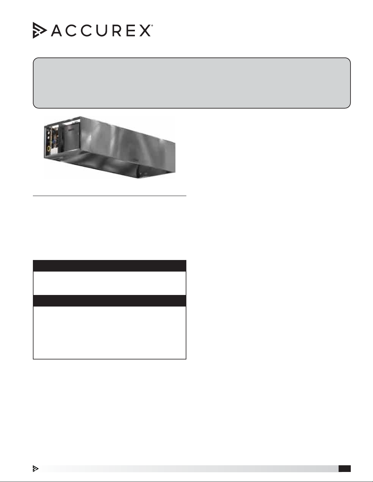
Auto Scrubber
Auto-Cleaning Hood
Installation, Operation and Maintenance Manual
Please read and save these instructions for future reference. Read carefully before attempting to assemble, install,
operate or maintain the product described. Protect yourself and others by observing all safety information. Failure
to comply with these instructions will result in voiding of the product warranty and may result in personal injury
and/or property damage.
Unpacking
Verify that all required parts and the correct quantity
of each item have been received. If any items are
missing, report shortages to your local representative
to arrange for obtaining missing parts. Sometimes it
General Safety Information
Only qualified personnel should install this system.
Personnel should have a clear understanding of these
instructions and all applicable local and national building
and fire codes. Personnel should be aware of general
safety precautions. SMACNA guidelines should be
followed for hanging and supporting the hood. If more
information is needed, contact a licensed professional
engineer before moving forward.
DANGER
Always disconnect power before working on or near a
unit. Lock and tag the disconnect switch or breaker to
prevent accidental power up.
NOTE
Follow all local electrical, plumbing and safety codes,
as well as the National Electrical Code (NEC) and the
latest edition of the National Fire Protection Agency
Standard for Ventilation Control and Fire Protection of
Commercial Cooking Operations, (NFPA 96). Follow
the Canadian Electrical Code (CEC) and ULC-S650 if
installing this product in Canada.
Receiving
Upon receiving the product, check to ensure all items
are accounted for by referencing the delivery receipt or
packing list. Inspect each crate or carton for shipping
damage before accepting delivery. Alert the carrier
of any damage detected. The customer will make
a notation of damage (or shortage of items) on the
delivery receipt and all copies of the bill of lading which
is countersigned by the delivering carrier. If damaged,
immediately contact your Accurex Representative. Any
physical damage to the unit after acceptance is not the
responsibility of Accurex, LLC.
is not possible that all items for the unit be shipped
together due to availability of transportation and truck
space. Confirmation of shipment(s) must be limited
to only items on the bill of lading. Filters are shipped
on a separate skid in their original packaging. Do not
remove factory packaging or install filters until just prior
to commissioning. Remove all other shipping/packing
materials.
Handling
Units are to be rigged and moved by the lifting brackets
provided or by the skid when a forklift is used. Location
of brackets varies by model and size. Handle in such
a manner as to keep from scratching or denting.
Damaged finish may reduce ability of unit to resist
corrosion.
Storage
Units are protected against damage during shipment. If
the unit cannot be installed and operated immediately,
precautions need to be taken to prevent deterioration of
the unit during storage. The user assumes responsibility
of the unit and accessories while in storage. The
manufacturer will not be responsible for damage during
storage.
The ideal environment for storage of the hood and
accessories is indoors, above grade in a clean, dry
atmosphere that is sealed from the elements. While in
storage, inspect equipment routinely. If any moisture,
dirt or other accumulations are found on the hood or
any of the parts, the source should be located and
eliminated.
Removing from Storage
As equipment is removed from storage to be installed
in their final location, it should be protected and
maintained as outlined in the Handling section above.
Auto Scrubber 1
Page 2

Table of Contents
Auto Scrubber Hood Function
General Safety Information . . . . . . . . . . . . . . 1
Receiving/Unpacking/Handling . . . . . . . . . . . 1
Storage/Removing from Storage . . . . . . . . . . 1
Auto Scrubber Hood Function . . . . . . . . . . . . . 2
System Components
Hood. . . . . . . . . . . . . . . . . . . . . . . . . 3
Auto Scrubber Control Panel . . . . . . . . . . . . 3
Backflow Preventer . . . . . . . . . . . . . . . . . 3
User Interface . . . . . . . . . . . . . . . . . . . . 3
Hood Weights . . . . . . . . . . . . . . . . . . . . . 3
Supply Plenum Weights and Dimensions . . . . . . . 4
Prior to Installation . . . . . . . . . . . . . . . . . . . 5
Unpacking . . . . . . . . . . . . . . . . . . . . . . . 5
Hood Installation Overview . . . . . . . . . . . . . 6-7
Filler Panel Installation . . . . . . . . . . . . . . . . . 7
Clearance Reduction Method . . . . . . . . . . . . 7-8
Top Clearance Reduction Options . . . . . . . . . 7
Back and Front Clearance Reduction Options . . . 8
End Clearance Reduction Method . . . . . . . . . 8
Installing Duct Collars
Exhaust Duct Collars . . . . . . . . . . . . . . . . 8
Supply Duct Collars to the Plenum . . . . . . . . . 8
Installing Back Supply Plenum . . . . . . . . . . . . 9
Ductwork
Exhaust/Supply . . . . . . . . . . . . . . . . . . . 9
Continuous Capture Plenum Hoods . . . . . . . . . . 9
Installing Front/Side External Supply Plenums . . . .10
Uni-Strut . . . . . . . . . . . . . . . . . . . . . . .10
Hanger Brackets and Threaded Rod . . . . . . . .10
Supply Duct Collar . . . . . . . . . . . . . . . . .10
Installing Backsplash / Side Splash Panels . . . . . .11
Installing End Skirts . . . . . . . . . . . . . . . . . .12
Plumbing
Connections . . . . . . . . . . . . . . . . . . . . .13
Detergent Tank Installation . . . . . . . . . . . . .13
Detergent Requirements . . . . . . . . . . . . . .13
Preventative Maintenance . . . . . . . . . . . . . .13
Typical Plumbing Connection Layout . . . . . . . .14
Electrical Connections
Wiring . . . . . . . . . . . . . . . . . . . . . .15-16
Typical Electrical Connection Layout . . . . . . . .17
Installing Ceiling Enclosure Panels . . . . . . . . . .18
Double Island Canopy Style Hoods . . . . . . . . . .18
Initial System Start-Up . . . . . . . . . . . . . . . . .19
System Operation
Fan Operation . . . . . . . . . . . . . . . . . . . .19
Hood Light Operation . . . . . . . . . . . . . . . .19
Wash Operation . . . . . . . . . . . . . . . . . . .20
Wash Sequence of Operation . . . . . . . . . . . 21-22
Airflow Testing Procedure . . . . . . . . . . . . . . .23
Additional Wiring Schematics
Ansul® and Amerex® Wiring Plan View . . . . . .24
Maintenance
Filters and Capture Tank . . . . . . . . . . . . . .25
Auto Scrubber Start-Up Checklist . . . . . . . . . . .26
Troubleshooting . . . . . . . . . . . . . . . . . . 27-29
Replacement Parts. . . . . . . . . . . . . . . . . . .30
Maintenance Log. . . . . . . . . . . . . . . . . . . .31
Our Commitment. . . . . . . . . . . . . . . Backcover
Accurex’s Auto Scrubber hoods are designed for three
primary functions:
• Capture and contain the effluent produced by the
cooking process.
• Remove grease and other contaminants from the
airstream with either one or multiple stages of
mechanical filters.
• Wash the filters and other surfaces within the exhaust
plenum to remove contaminants.
NOTE
The wash sequence of the hood is not designed for
fire suppression and will not engage in the event of
afire.
NOTE
For information on the complete wash cycle, please
refer to the Wash Sequence of Operation, pages 21
and 22.
Auto Scrubber2
Page 3
System Components Hood Weights
Hood
The hood is shipped from the factory pre-piped and
ready to install. All wash components within the hood
are complete and ready for connection to hot water,
sanitary sewer drain and the electrical sources. If the
Auto Scrubber Control Panel is mounted on the hood,
wiring from the control panel to the hood lights, valves
and sensors is completed by Accurex. All field plumbing
and wiring must conform to plumbing and electrical
codes.
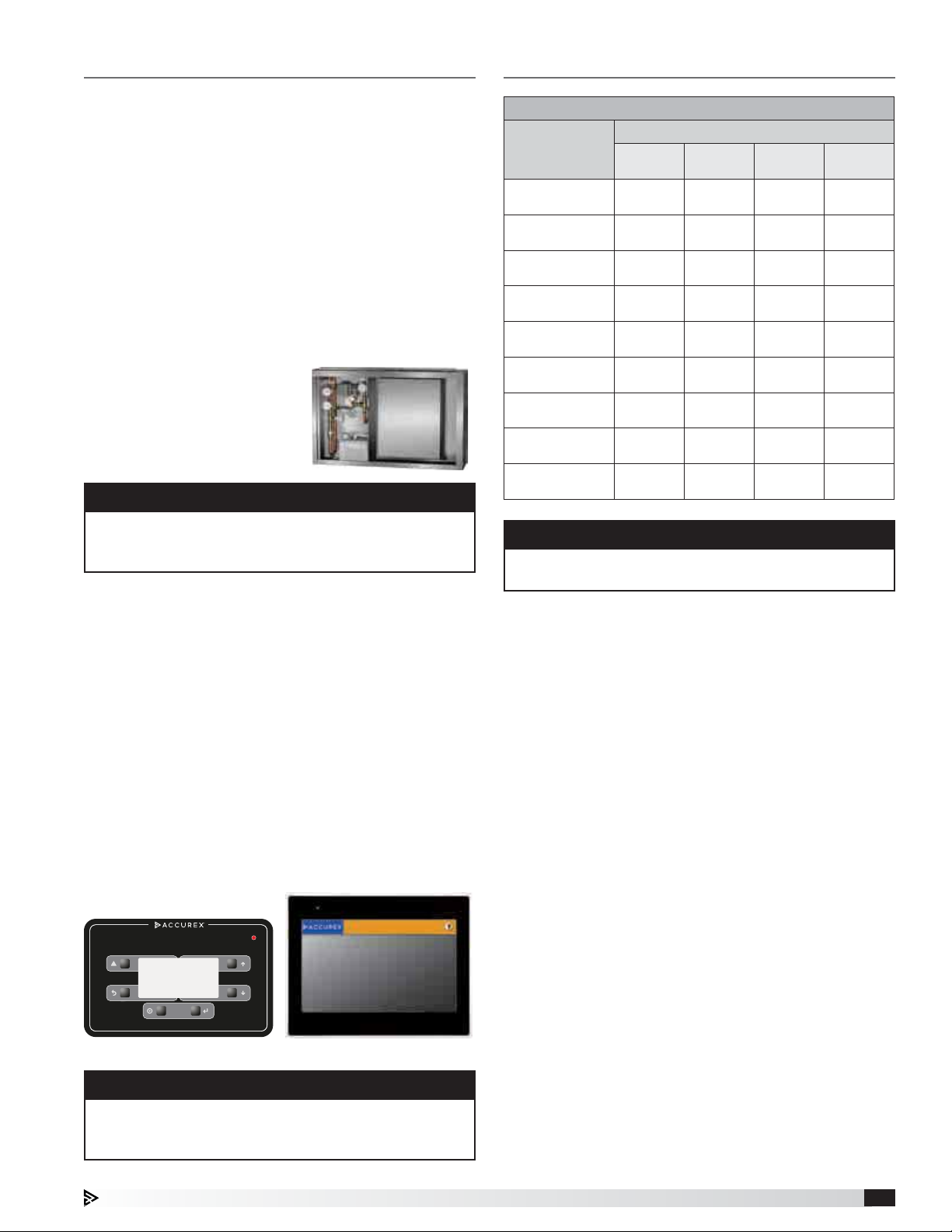
Auto Scrubber Control Panel (ASCP)
The control cabinet contains the water and electrical
components, including the Programmable Logic
Controller (PLC), that controls
the wash sequencing and
operations. The control
cabinet also includes the
detergent reservoir, detergent
pump, and other water piping.
NOTE
Filters are shipped loose with the hood and installed
in the field. To install the filters, perform the sequence
of steps outlined on page 25 in reverse.
Backflow Preventer
A backflow preventer will be shipped loose with the
ASCP and will need to be installed in-line with the hot
water supply to the ASCP to prevent detergent from
back-feeding into the building water supply. Plumbing
instructions begin on page 13.
Hood Weights
Hood Width
inches (cm)
48
(121.92)
51
(129.54)
54
(137.16)
57
(144.78)
60
(152.40)
63
(160.02)
66
(167.64)
69
(175.26)
72
(182.88)
4 feet
lbs. (kg)
244
(110.7)
250
(113.4)
256
(116.1)
262
(118.8)
268
(121.6)
274
(124.3)
280
(127.0)
286
(129.7)
292
(132.4)
Length
8 feet
lbs. (kg)
398
(135.2)
404
(183.3)
410
(186.0)
416
(188.7)
422
(191.4)
428
(194.1)
434
(196.9)
440
(199.6)
446
(202.3)
12 feet
lbs. (kg)
553
(250.8)
559
(253.6)
565
(256.3)
571
(259.0)
577
(261.7)
583
(264.4)
594
(269.4)
600
(272.2)
606
(274.9)
CAUTION
To ensure proper structural support, all hanger
brackets must be used for hanging the hood.
16 feet
lbs. (kg)
707
(320.7)
713
(323.4)
719
(326.1)
725
(328.9)
731
(331.6)
737
(334.3)
743
(337.0)
749
(339.7)
755
(342.5)
User Interface
The user interface will be either a keypad with LCD
screen or touch screen. It can be mounted on the Auto
Scrubber control cabinet, hood or shipped loose for
remote mounting. It will provide a WASH button (WASH
ON/OFF with touch screen), and a means of turning
on/off hood fans and lights, if applicable. It also includes
system alarm notifications to alert of any faults on the
system, such as a low detergent alarm.
SYSTEM FAULT
MENU
NAV
Keypad Touch Screen
NOTE
For detailed information on the Auto Scrubber Control
Panel (ASCP), please refer to the Accurex website,
www.accurex.com
Auto Scrubber 3
Page 4
Supply Plenum Weights and Dimensions
External Supply
Plenum Type
Air Curtain Supply (ASP)
Split Air Curtain Supply
(Split ASP)
lbs/ft kg/m in. mm in. mm ft. m
Refer to Air Curtain
Supply Plenum
Weight Table
15.5 23.07 24 609.6 10 254.0 3 to 16 .91 to 4.88
Weight Width Height Length per section
Refer Air Curtain
Supply Plenum
Weight Table
10 to 24 254.0 to 609.6 10 254.0 3 to 16 .91 to 4.88
Back Supply (BSP) 35.0 52.09 6 152.4 Variable Variable 3 to 16 .91 to 4.88
Horizontal Supply (HSP) 14.0 20.83 12 304.8 18 457.2 3 to 16 .91 to 4.88
Variable Supply (VSP) 16.0 23.81 12 304.8 18 457.2 3 to 16 .91 to 4.88
Weight
10 11 12 13 14 15 16 17 18 19 20 21 22 23 24
Air Curtain Supply Plenum Width (inches)
lbs/ft 8.3 8.6 8.9 9.2 9.5 9.8 10.1 10.4 10.7 11.1 11.3 11.6 11.9 12.2 12.5
kg/m 12.35 12.80 13.24 13.69 14.14 14.58 15.03 15.48 15.92 16.52 16.82 17.26 17.71 18.16 18.60
Auto Scrubber4
Page 5
Prior to Installation
Unpacking
Prior to installation, check with the Authorities Having
Jurisdiction (AHJ) on clearance requirements to
structures surrounding the hood and other equipment.
Verify there is enough space to safely lift the hood up
into its operating position and enough clearance around
the hood for components like fire system connections,
hood lights, hood control components, plumbing
connections, etc. Consider access for servicing the
equipment and the different components when locating
the hood.
The UL label located on the end panel on the inside of
the hood will provide pertinent information regarding the
hood installation. Information includes:
• Allowable cooking surface temperatures of the
cooking equipment
• Front and side overhang requirements
• Minimum exhaust airflow requirements
• Hood lights load information and restrictions
• Filter information
• Fire damper fusible link replacement information, if
applicable
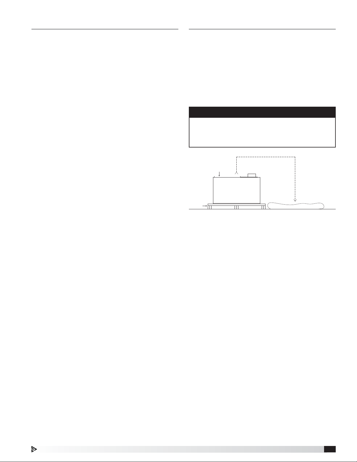
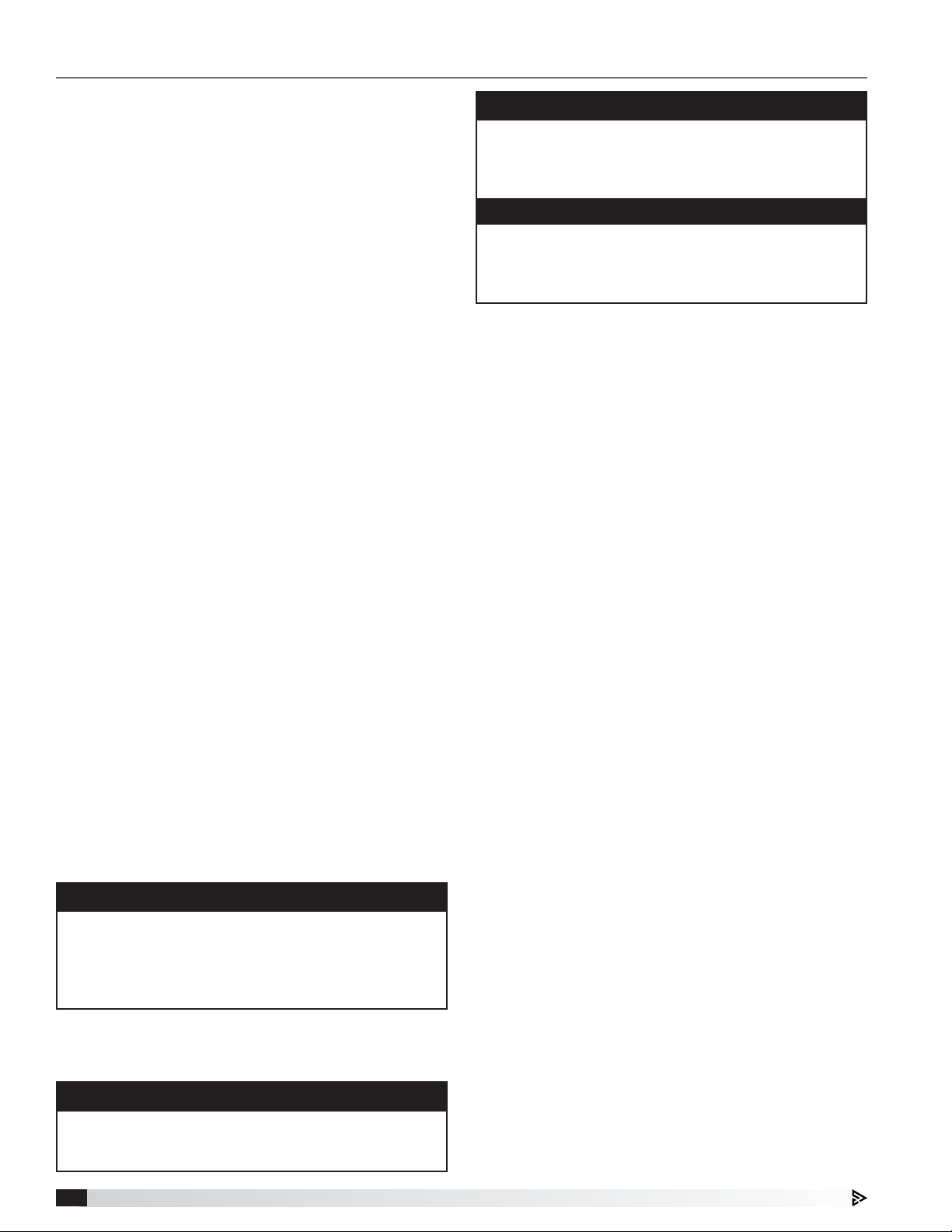
Carefully remove the top of the crate and set aside all
accessories in the crate such as backsplash panels,
control packages, and boxes with loose parts. When
removing the hood from the crate, place protective
material on the floor next to the crate to avoid damaging
the hood.
Lift the hood only by utilizing the hanger brackets. Make
sure the hood weight is evenly distributed. Slowly lift
the hood out of the crate and place on the protective
material.
NOTE
If using straps, the straps should not interfere with
plumbing on the top of the hood in an effort to prevent
internal piping damage which could cause future
leaks.
Top of Hood
Pallet
Protective Material
Auto Scrubber 5
Page 6
Hood Installation Overview
It is recommended that the protective plastic sheeting
remain on the hood until fully installed to better protect
the product from scratching and marking. Once
removed, use stainless steel polish, such as BlueAway
or equivalent, to clean the hood and/or remove marks
or discoloration. Be sure to wipe with the grain and not
against it.
1. If the hood is provided with filler panels, shipped
loose, install them now. See page 7, Filler Panel
Installation. Filler panels may be integral to the
hood, which requires no additional installation.
2. If the hood is equipped with Clearance Reduction
Methods, refer to pages 7 and 8 for special
considerations with hanging the hood.
3. If the hood is provided with hood/duct sensors or
thermostats that were shipped loose, install them
now. See the Installation and Operations guide
provided with the control panel.
4. If the hood was provided with either exhaust
collars or supply collars that have shipped loose,
it is recommended that the exhaust and supply
openings are cut and collars are attached now,
prior to hanging the hood. See Installing Duct
Collars on page 8.
5 If the hood is provided with a back supply plenum
(BSP) install it now. See page 9, Installing the Back
Supply Plenum.
6. If possible, connect (weld) exhaust duct to the
hood while on the floor, unless it prohibits the hood
from being raised into place. For information on
ductwork, see page 9, Ductwork.
7. At this point, drill holes in the building structural
support system or utilize uni-strut to match up with
the hanger bracket holes. Then slowly and evenly
raise the hood into position and insert 1/2-inch
(12.7mm) diameter threaded rod (provided by
others) between the hanger brackets and structure.
The hood hanging height requirements are given on
the UL label. Typical canopy hood hanging height
will be 80inches (198.12cm) off the finished floor.
NOTE
If the hood is supplied with ceiling enclosure panels,
the height of the enclosures will typically be the
distance from the ceiling to the top of the hood. Use
this dimension to find the hood’s hanging height off of
the floor.
For questions regarding the supporting structure and
its integrity, either the contractor or structural engineer
needs to be consulted.
NOTE
All hanger brackets MUST be used and the hood must
be properly supported while lifting to prevent damage
or distortion to the hood.
NOTE
Ensure the hood is hung evenly to prevent drainage
problems. Provide adequate support so that the hood
does not move in a manner that is unacceptable to
the Authorities Having Jurisdiction (AHJ).
WARNING
When mounting the hood or any components against
the hood, never puncture or drill into the canopy
unless otherwise instructed in this manual. Doing so
will void the hood listing and warranty.
8. If the hood was provided in sections with the
continuous capture option, once each hood
section is hung, install this option now. See page 9,
Continuous Capture Plenum Hoods.
9. If the hood was provided with any front or side
external supply plenums (other than the back
supply plenum), install these now. See page 10,
Installing Front/Side External Supply Plenums.
10. Install the remainder of both the exhaust and
supply ductwork. For further guidelines see page 9,
Ductwork.
11. If the hood is provided with any backsplash/
sidesplash panels, install them now. See page 11,
Installing Backsplash Panels.
12. If the hood is provided with any end skirts, install
them now. See page 12, Installing End Skirts.
13. This is a Type I hood and it requires a fire
suppression system. Once the hood(s) and
ductwork are fully installed, appliance(s) are in
place and walls are complete, the fire system
should be completed.
If the hood is provided with a full factory-
coordinated fire suppression system installation,
the certified fire system installer should be
contacted at this time to complete the final
hookups, testing and system certification based
upon manufacturer’s specification and local fire
codes.
If the hood is equipped with pre-piping only, and/
or does not include fire suppression, it is the
responsibility of a certified fire system installer
to install, test and certify the system based upon
manufacturer’s specification and local fire codes.
14. The Auto Scrubber Control Panel (ASCP), if
shipped loose, will need to be installed at this time.
Once mounted, plumbing and electrical wiring
will need to be completed by the jobsite plumber
and electrician. Typical site wiring responsibilities
include wiring hood temperature sensors, hood
lights, hood sequencing valves, fire suppression
micro-switches, and fans (if applicable) to the
control panel. Hood plumbing details are given on
page 13-14, and hood electrical wiring details are
provided on page 15-17.
Auto Scrubber6
Page 7
Hood Installation Overview, continued
Clearance Reduction Methods
15. If the hood is provided with enclosure panels,
install them now. See page 18, Installing Enclosure
Panels.
16. Install the rest of the hood accessories provided.
This may include grease filters or condensate
hood baffles, grease cups, light bulbs (provided by
others unless LED tube style), light globes, and trim
strips.
Filler Panel Installation
1. Uncrate the hood and lay it on the floor with
protective material between the hood and the floor.
2. Bolt the filler panels together with 5/16 in. bolts
provided in the hardware package.
3. Position the filler panels to the hood back, and tack-
weld them into place.
HOOD
Clearance reduction methods have been evaluated and
tested and are listed by UL (Underwriters Laboratory).
The method of test was derived from the UL 710 test
standard.
The hood may be installed with zero clearance to
combustible materials if constructed in the following
manner.
1. One inch (2.54 cm) thick layer of insulation of Owens
Corning
®
Type 475, Johns Manville Type 475, IIG®
MinWool-1200® Flexible Batt, or Knauf Insulation
Type EI 475.
2. Insulation must be held securely in place. Pins that
are welded or secured with an adhesive may be
used.
3. A backsplash panel must be attached to the wall
(insulated or uninsulated).
To comply with the UL Listing, the cooking appliances
must be as follows:
• Maximum surface temperature is 700°F (371°C)
• Appliances are located at least 3 in. (7.62 cm) from
the rear wall
• Appliances are at least 40 in. (101.6 cm) below the
bottom front edge of the hood
The hood may be installed with 3 in. (7.62 cm) clearance
to limited combustible materials per NFPA 96 if
constructed in one of the following methods:
• 3 in. (7.62 cm) rear uninsulated stand-off
• 3 in. (7.62 cm) top enclosure panel system
• 3 in. (7.62 cm) end uninsulated stand-off
Top Clearance Reduction Options
One inch (2.54 cm) layer of insulation installed on top
of the hood (optional) meets zero inch requirements for
clearance to combustible surfaces as outlined under the
clearance reductions methods.
HOOD
HOOD
TACK-WELDED TO
HOOD BACK
5/16 IN. X 3/4 IN. BOLTS
WITH WASHERS & NUTS
RIGHT FILLER PANEL
BOTTOM FILLER PANEL
4. To allow for ease of cleaning, caulk the external
seams with NSF Approved silicone caulk (GE
SCS1009, or its equivalent). The caulk is not
provided.
Three inches (7.62cm) uninsulated airspace installed on
top of hood (optional) meets NFPA 96 requirements for
clearance to limited combustible surfaces.
Auto Scrubber 7
Page 8
Back and Front Clearance
Reduction Options
One inch (2.54 cm) layer of insulation in 3 in. (7.62cm)
back stand-off meets zero inch requirements for
clearance to combustible surfaces as outlined under the
clearance reduction methods.
Three inches (7.62 cm) uninsulated back stand-off
meets NFPA 96 requirements for clearance to limited
combustible surfaces.
One inch (2.54 cm) layer of insulation factory-installed
on the front of the hood (optional) meets zero inch
requirements for clearance to combustible surfaces.
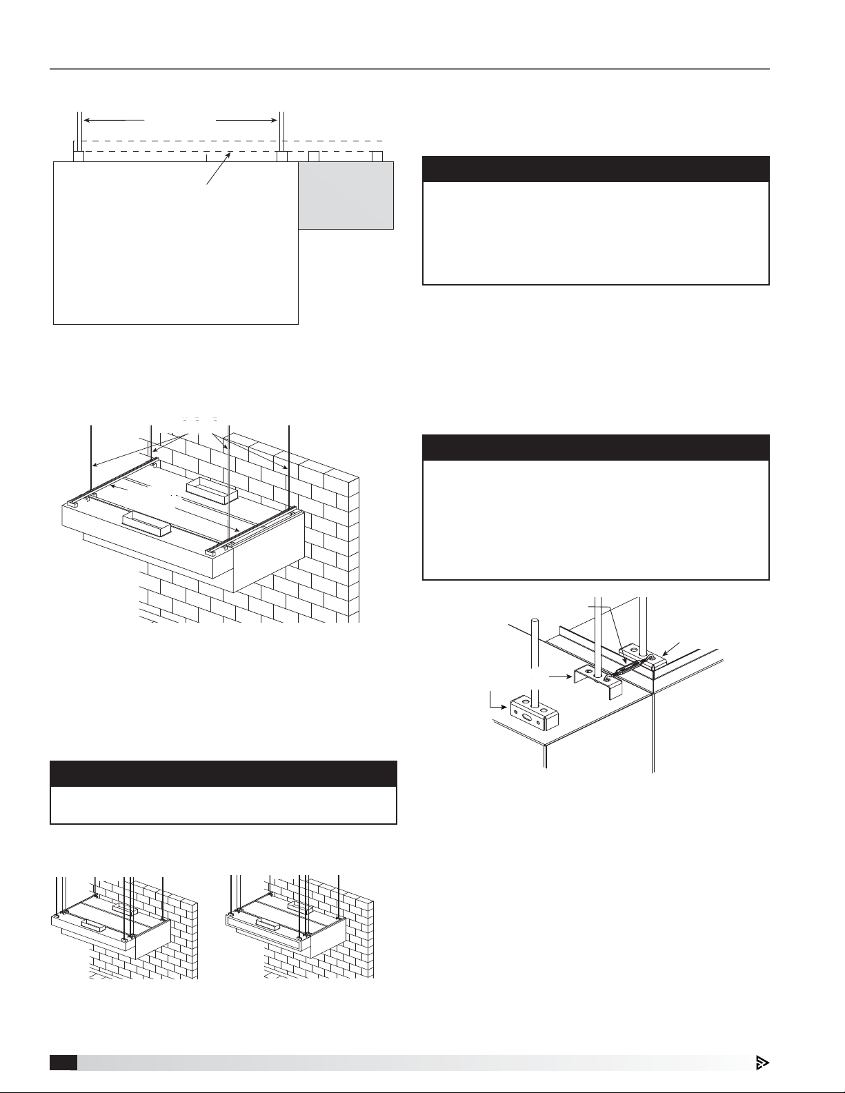
Installing Duct Collars
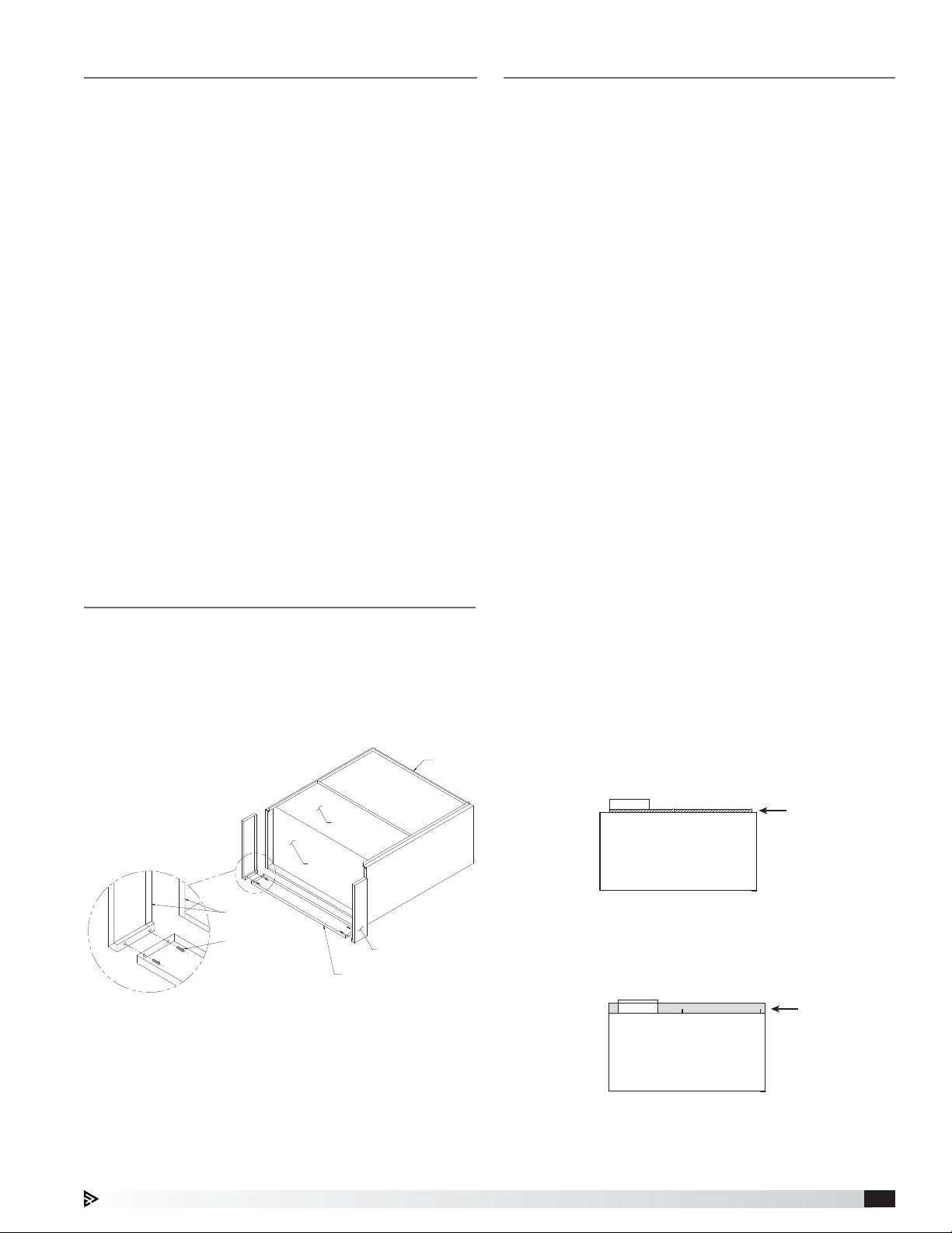
Exhaust Duct Collars
1. The exhaust duct connection needs to be located
within 48 in. (121.92 cm) from the center of the hood
length to the center of the duct connection and
within shaded area as shown.
Top View of the Hood
8 in.
Hanger Bracket
Exhaust Plenum
Duct cut out area
8 in.
14 in.
3 in.
Hood
Width
End Clearance Reduction Options
One inch (2.54 cm) layer of insulation factory-installed
on the end of the hood (optional) meets zero inch
requirements for clearance to combustible surfaces
under the clearance reduction methods.
Three inches (7.62 cm) uninsulated airspace installed on
end of hood (optional). Meets NFPA 96 requirements for
clearance to limited combustible surfaces.
Hood Length
Front of hood
NOTE
An 8x8x4-inch enclosure and sequencing solenoid
valves will be mounted on top of the Auto Scrubber
hood near the right or left-hand side. Avoid
interference with these items by keeping the exhaust
collars 20 inches from the end of the hood where
these components are mounted.
2. The exhaust duct connection is to be a continuous
liquid-tight weld. Weld with a non-ferrous filler wire,
such as silicon bronze or stainless steel filler wire.
Protect all stainless steel areas from weld splatter.
Supply Duct Collars to the Plenum
Place the duct collar(s) over the opening, fastening
with tack-welds at 1 to 2 in. (2.54 to 5.08 cm) intervals,
or sheet metal screws at 3 to 6 in. (7.62 to 15.24 cm)
intervals.
3 in.
Auto Scrubber8
Page 9
Installing the Back Supply Plenum
BOLT OR WELD
HOOD TOP
HOOD END
SUPPORT ANGLES
CAULK
BOLT
U-CLIP
HOOD
ACORN
NUT
2. RAIS
AND
3. FAST
4. FAST
5. CAU
& CAP
1. REM
HOOD FRONT
HOOD FRONT
REMOVE
SUPPORT
ANGLES ON
THE OPEN
END PANEL
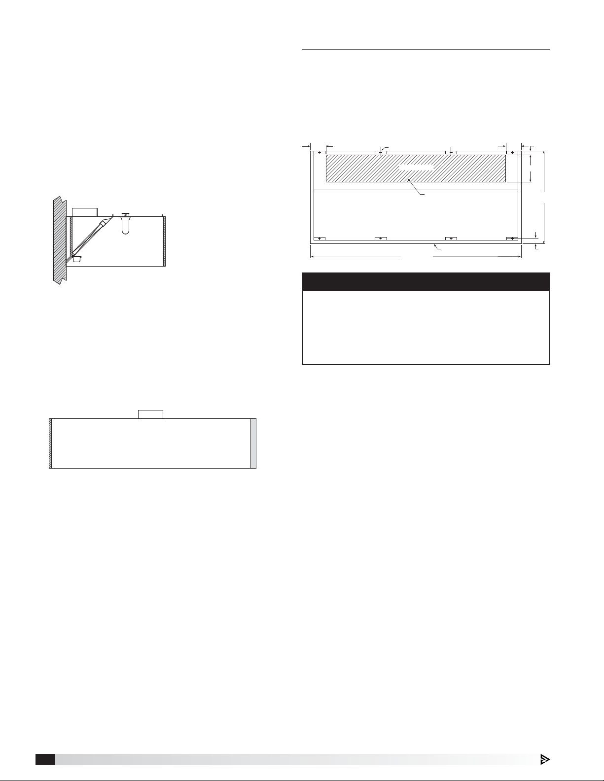
Ductwork
Install the Supply Duct Collar
1. Find the center of the back supply plenum.
2. If the back supply plenum is to have
one opening, cut the opening such
that it is centered at L /2 from the
plenum end. (Fig.1)
3. If the back supply plenum is to have
two openings, cut openings such
that they are centered at L /4 from
each end of the plenum.
(Fig. 2)
4. Place the duct
L/4
collar(s) over the
opening(s), fastening
with screws or
tack-welds every
4 to 6 in. (10.16 to
15.24cm). (Fig. 3)
Hang the Plenum
Fig. 2
5. Hang the back
supply plenum
from the ceiling.
The back supply plenum
needs to be mounted 31.25in.
(79.375 cm) above the finished
floor. This is measured from
the lowest rear edge of the
back supply plenum to the
finished floor. (Fig. 4)
Hang using threaded rod
placed through the hanger brackets.
6. Fasten the back supply to the wall, going through the
lower back supply wall.
L (MODULE LENGTH)
L/2
Fig. 1
L (MODULE LENGTH)
L/2
Fig. 3
L/2
L/4
Exhaust - As specified in NFPA 96, Ch. 7.5 (latest
edition), exhaust duct systems must be constructed in
the following manner:
Materials: Ducts shall be constructed of and supported
by carbon steel not less than 1.37 mm (0.054 in.) (No.
16 MSG) in thickness, or stainless steel not less than
1.09 mm (0.043 in.) (No. 18 MSG) in thickness.
Installation: All seams, joints, penetrations, and duct to
hood collar connections shall have a liquid-tight external
weld. If you have an automatic fire damper, please refer
to that manual for installation instructions now.
Supply - Supply ductwork (where applicable) should
be connected to the hood in a manner approved by the
local code authorities.
NOTE
For hoods with fire dampers in the exhaust and
supply duct collars, an access panel for cleaning and
inspection shall be provided in the duct. This panel
shall be as close to the hood as possible but should
not exceed 18 in. (45.72 cm).
For proper installation of duct collars when they are
shipped unattached, see page 8.
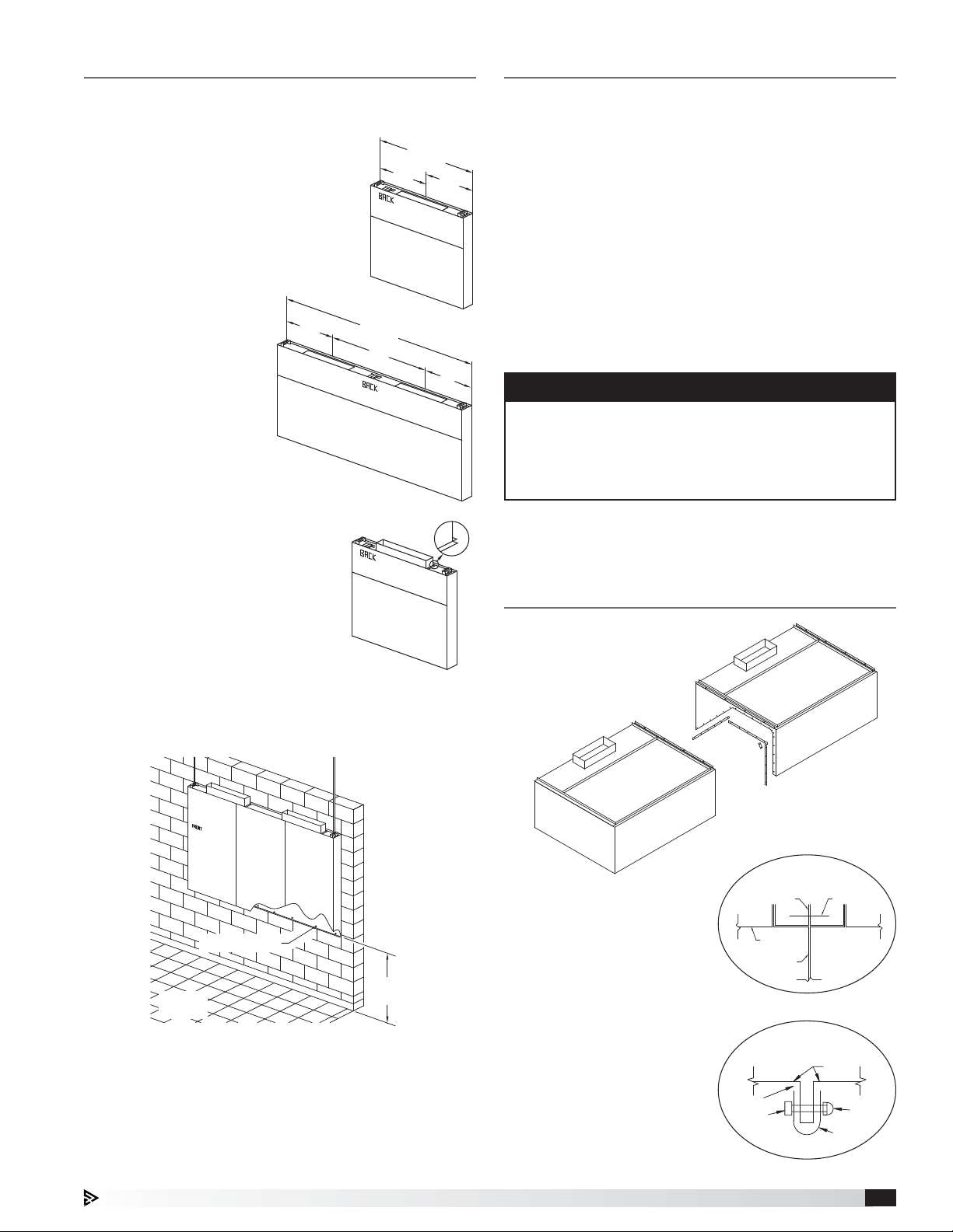
Continuous Capture Plenum Hoods
1. Remove the support angles
provided for support during
shipping on the open
end panels. Install
and level both
hoods.
FASTENERS HOLDING THE
BACKSUPPLY TO THE WALL
31.25 INCH
CRITICAL
Fig. 4
DIMENSION
• These fasteners are to help maintain the location of
the back supply, and are not intended to hold the
weight of the back supply unit.
• The fasteners should not interfere with the
removable air diffusers.
2. After leveling, secure the
hoods together by tackwelding and/or bolting the
angles that are located at
the top of the hoods along
its width (Fig. 5).
3. Next, fasten the hoods
together at its inside
plenum profile using
u-clips and bolts (Fig.6).
Caulk this joint with NSF
Approved silicone caulk
(GE SCS1009 or its
equivalent). The caulk is
not provided.
Fig. 5
Fig. 6
Auto Scrubber 9
Page 10
Installing Front/Side External Supply Plenums
Using Uni-strut
THREADED ROD
SUPPLIED BY OTHERS
UNI-STRUT (U-CHANNEL)
SUPPLIED BY OTHERS
END VIEW
HOOD
The uni-strut (supplied by others) supporting the hood
may be cantilevered over the end of the hood. Utilizing
the external supply plenum’s hanger brackets, securely
fasten to the uni-strut.
THREADED
THREADED
ROD
ROD
UNI-STRUT
UNI-STRUT
(U-CHANNEL)
(U-CHANNEL)
EXTERNAL
SUPPLY
PLENUM
1. Insert 1/2 in. (12.7 mm) diameter threaded rod (by
others) into hanger brackets on the external supply
plenum top. Raise and hang the external supply
plenum from adequate roof or ceiling supports.
NOTE
Ensure the external supply plenum is installed
flush with the hood front and is plumb and level by
adjusting the threaded rod(s). There should be no gap
between the bottom of the external supply plenum
and the hood after installation and adjustments are
completed.
2. The external supply plenum should be resting
lightly against the hood. The hood is only used to
position the plenum; it is not intended to support the
plenum. All hanger brackets on the external supply
plenum must be used and the plenum must be
properly supported while lifting to prevent damage or
distortion. The external supply plenum must be level
to operate properly.
NOTE
After hanging, secure the external supply plenum to
the hood (or to another external supply plenum) using
the supplied turnbuckle(s). Use caution tensioning the
turnbuckle. Too much tension may cause the bottom
of the external supply plenum to pull away from the
hood or cause the face of the hood to become
deformed.
Air Curtain Supply (ASP)
Horizontal Supply Plenum (HSP)
Variable Supply Plenum (VSP)
Mounted with uni-strut and threaded rod
When using uni-strut (supplied by others), it must be
bolted to the hood and external supply plenum hanger
brackets.
NOTE
The uni-strut needs to be the full length of the hood
and the external supply plenum.
Using Hanger Brackets and Threaded Rod
Air Curtain
Supply Plenum (ASP)
Horizontal Supply Plenum (HSP)
Variable Supply Plenum (VSP)
TURNBUCKLE
TURNBUCKLE
HOOD HANGER
HOOD HANGER
BRACKET
BRACKET
EXTERNAL
EXTERNAL
SUPPLY PLENUM
SUPPLY PLENUM
HANGER BRACKET
HANGER BRACKET
HOOD
EXTERNAL
SUPPLY
PLENUM
3. It is recommended that caulk be applied at the
mating seams and surfaces of the external supply
plenum, the hood, and the wall. If the external supply
plenum is next to a wall, you will need to caulk
around the surface next to the wall. Caulk the joints
with NSF Approved silicone caulk (GE SCS1009, or
its equivalent). The caulk is not provided.
Installing the Supply Duct Collar to
thePlenum
Place the duct collar(s) over the opening, fastening
with tack-welds at 1 to 2 in. (2.54 to 5.08 cm) intervals,
or sheet metal screws at 3 to 6 in. (7.62 to 15.24 cm)
intervals.
Auto Scrubber10
Page 11

Installing Backsplash/Sidesplash Panels
Flat Backsplash/Sidesplash Panel
Material: Stainless
NOTE
• Panel length up to 47.25 inches (1200.15mm) wide
ship in one piece; panel lengths over 47.25inches
(1200.15mm) ship in multiple pieces when panel
height is <66 inches (1674.4 mm) or >80inches
(2032mm).
• Panel length up to 48 inches (1219.2 mm) wide
ship in one piece; panel lengths over 48inches
(1219.2mm) ship in multiple pieces when panel
height is ≥66 inches (1676.4 mm) or ≤80 inches
(2032 mm).
Insulated Backsplash/Sidesplash Panel
Material: Stainless
Insulation: 1 in. (25.4 mm)
Panels up to 45 in. (1143 mm) wide ship in one piece;
over 45 in. (1143 mm) in multiple pieces.
HOOD END PANEL
1 IN. (25.4 MM)
WALL
HEIGHT
LENGTH
NOTE
HOOD FRONT PANEL
1. After hood is hung into position, slide the flat flange
of the backsplash/sidesplash panel behind the
back/side of the hood. If the hood is provided with
flat backsplash/sidesplash panels, divider bars will
be provided. Install divider bars between panels
as shown in the flat backsplash/sidesplash panel
section view.
2. After the panels and dividers have been positioned,
drill holes in the panel and fasten to the wall.
(Fasteners provided by others). The holes should be
spaced to adequately secure the panel to the wall.
3. Caulk the joints between the hood and the panel
with NSF Approved silicone caulk (GE SCS1009 or
its equivalent). Caulk provided by others.
4. Caulk the joint between the panels when multiple
insulated panels are required with NSF Approved
(GE SCS1009 or its equivalent). Caulk provided by
others.
SLIDE FLANGE
BEHIND BACK
OF THE HOOD
BACKSPLASH PANEL
SECTION VIEW
OF BACKSPLASH
PANEL OVERLAP
Auto Scrubber 11
Page 12

Installing End Skirts
1. After the hood is hung in position, line up the top of
the end skirt with the end panels of the hood.
2. Drill a hole in the hood end panel to line up with
the hole in the end skirt. Attach the end skirt with a
1/4in. bolt and cap nut to the inside of the hood, or
tack-weld the end skirt to the hood.
3. Position the end skirt against the wall and attach.
The method depends on the wall construction.
(Fasteners provided by others).
4. Caulk the internal joint formed by the end skirt and
the hood end panel with NSF Approved silicone
caulk (GE SCS1009 or its equivalent). The caulk is
not provided.
5. To allow for ease in cleaning, also caulk all the
external seams.
HOLE DRILLED
BY INSTALLER
1/4 INCH BOLT AND CAP NUT
SUPPLIED BY MANUFACTURER
FULL END SKIRT
ATTACH TO WALL
FASTENERS BY OTHERS
HEMMED EDGE
Auto Scrubber12
Page 13

Plumbing Connections
TOP VIEW OF AUTO SCRUBBER CONTROL PANEL (ASCP)
4
5
FRONT VIEW OF AUTO SCRUBBER CONTROL PANEL (ASCP)
22
8
1. Electrical Control Cabinet 5. Hot Water Inlet Connection
2. Detergent Pump 6. Cold Water Outlet Connection to Hood
3. Detergent Tank 7. Cold Water Inlet Connection
4. Hot Water Outlet Connection to Hood 8. Inlet Valve
1. Install the factory
6
1
7
1
3
FROM 1 INCH
HOT WATER SUPPLY
provided backflow
preventer (shipped
loose) and drain
TO ASCP 1 INCH
HOT WATER INLET
connection per
local codes.
Backflow Preventer
2. Bring 1-inch hot water supply line to the backflow
preventer.
3. Plumb 1-inch line from outlet of backflow preventer
to the hot water inlet in the control cabinet.
4. If the cabinet is remote mounted, connect the hot
water outlet on the controls cabinet to the hot water
inlet on the top of the hood.
5. If system is configured for cold water mist, bring
0.75-inch water piping to the cold water mist inlet in
the control cabinet.
6. If the cabinet is remote mounted and the system
is configured for cold water mist, connect the cold
water mist outlet on the controls cabinet to each
hood with a cold water mist solenoid valve
7. Plumb 2-inch drain on each hood to grease trap
(floor).
NOTE
• Hot water temperature should be 140°F.
• While the hood is washing, water pressure in the
control panel should be between 40 and 70 PSI.
• Cold mist water pressure should be between 20
and 40 PSI.
Detergent Tank Installation
The detergent tank is located in the plumbing section
of the ASCP. The tank provided can hold up to
2.5gallons of detergent. It will need to be checked
periodically depending on detergent use and filled with
the recommended chemical detergent. The tank is also
equipped with a float that will trigger an alarm to warn
the user when detergent is low.
Steps for removal and installation of the detergent tank
are as follows:
Removal:
1. Disconnect the two float switch wires at the quick
connect electrical fittings.
2. Remove the 1/4-inch detergent line that enters the
tank thru the screw on cap.
3. Lift out the detergent tank from the utility cabinet.
4. Unscrew the 63 mm cap from the tank; this will
remove the float assembly.
5. Fill the tank with the approved detergent.
Install:
1. Install the 63 mm cap and float assembly into the
detergent tank.
2. Lift the detergent tank back into the utility cabinet.
3. Install the 1/4-inch detergent line thru the hole in the
63 mm cap.
4. Connect the two float switch wires at the quick
connect electrical fittings.
Detergent Requirements
Detergent model X-701 manufactured by ZEP, Inc., is
recommended by Accurex for use in the wash system.
This product is biodegradable, non-caustic, and safe
for kitchen staff to use. If X-701 detergent is not used,
the cleanliness of the exhaust plenum and filters cannot
beguaranteed.
NOTE
• X-701 is manufactured by ZEP, Inc., Atlanta, GA,
USA. For details and ordering information, call
1-800-371-6858.
• If washed once a day, the 2.5 gallon detergent tank
will last approximately 24 to 30 days depending on
filter type.
Preventative Maintenance
The following practices will prolong the life of the
detergent pump:
• Keep detergent tank filled.
• Avoid spilling detergent on the exterior of the pump.
• Clean the detergent tank at least every six months.
• Clean the detergent line strainer at least every six
months.
• Check tightness of all fittings periodically.
The detergent pump motor has sealed bearings which
do not require lubrication.
Auto Scrubber 13
Page 14

Typical Plumbing Connection Layout
Building
Water
Supply
DD
Backflow Preventer
Provided by Accurex; field installed
Drain required for backflow preventer
Plumbing connections made here
C
B
BAA
C
E
E
First Auto
Scrubber Hood
Auto Scrubber Control Panel
(ASCP)
Plumbing Key
Hot Water Piping
Cold Water Piping
HOT WATER CONNECTIONS:
A 1-inch hot water supply from building to Backflow Preventer
B 1-inch hot water piping from Backflow Preventer to control cabinet
C 1-inch hot water piping from control cabinet to hood(s)
COLD WATER CONNECTIONS, optional with continuous cold water mist
D 3/4-inch cold water supply from building to control cabinet
E 3/4 inch cold water piping from control cabinet to hood(s)
DRAIN CONNECTIONS FROM AUTO SCRUBBER HOOD(S):
F 2-inch male NPT connection to building drain with grease trap (one per hood section)
FF
Each additional
Auto Scrubber Hood
(if applicable)
F
F
Auto Scrubber14
Page 15

Electrical Connections
NOTE
All wiring of electrical equipment must be done to
meet NEC and local codes.
NOTE
It is recommended that shielded wire be used for all
low voltage connections (24V or less) to prevent signal
interference with other high voltage circuits.
WARNING
All 115 VAC field wiring (or higher) must be high
temperature rated and must be routed through hard
or flex conduit. All low voltage field wiring should be
plenum rated if not routed through conduit. All field
wiring should not come in contact with the surface of
the hood.
This section will provide some field wiring information
for connections directly to the hood. For all other wiring
connection requirements for the Auto Scrubber Control
Panel (ASCP), please refer to both the Auto Scrubber
Control Panel Installation, Operation and Maintenance
manual and the job specific wiring diagram located on
the inside door of the control cabinet.
Hood Lights
If the hood is provided with lights, a junction box will be
located on top of the hood for field connections. Use
minimum 14 AWG copper wire. Light bulbs will not be
provided (unless equipped with LED tube style fixtures).
For incandescent or compact fixtures, standard light
bulbs up to 100 watts may be used.
• 115 VAC, power for hood lights, one per light circuit
(Terminals H1, N1 | H2, N2 | H3, N3 | H4, N4)
• 115 VAC, power to lights, one per light circuit
(Terminals B1, W1 | B2, W2 | B3, W3 | B4, W4)
EACH CANOPY LIGHTING CIRCUIT MUST NOT EXCEED 15A TOTAL CURRENT
LIGHT CIRCUIT 1: 115 VAC, 15 AMPS FROM BREAKER
R__
11
H1 W1B1
14
HOOD LIGHT
RELAY 1
HOOD LIGHT(S)
WH 14GABK 14GA BK 14GA
G
N1
Keypad - if equipped
• Connect factory provided cable from back of keypad
to CAREL® PCO5+ controller (Terminal J10)
CONNECT FACTORY PROVIDED RJ25 CABLE
TO J10 ON PCO5+ AND BACK OF KEYPAD
PCO5+ J10 KEYPAD
35 Foot Cable Provided
75 or 150 Foot Cable is Optional
Touch Screen - if equipped
Power Wiring
• Connect factory provided 2-wire cable from Vari-Flow
(Terminals TS24, TSC) to touch screen
(Terminals G, GO)
Control Wiring
• Connect factory provided 3-wire cable from Vari-Flow
(Terminals -, +, GND) to touch screen
(Terminals -, +, GND)
POWER WIRING
TOUCH
TS24
TSC
SCREEN
GO
G
CONTROL WIRING
TOUCH
-
+
GND
J25 (BMS2)
SCREEN
-
+
GND
LIGHT CIRCUIT 2: 115 VAC, 15 AMPS FROM BREAKER
R__
11
BK 14GA
H2 B2 N2W2
LIGHT CIRCUIT 3: 115 VAC, 15 AMPS FROM BREAKER
BK 14GA BK 14GA
H3 B3 N3W3
LIGHT CIRCUIT 4: 115 VAC, 15 AMPS FROM BREAKER
BK 14GA BK 14GA
H4 B4 N4W4
14
HOOD LIGHT
RELAY 2
R__
11
14
HOOD LIGHT
RELAY 3
R__
11
14
HOOD LIGHT
RELAY 4
WH 14GABK 14GA
HOOD LIGHT(S)
WH 14GA
HOOD LIGHT(S)
WH 14GA
HOOD LIGHT(S)
CAUTION
For multiple hood systems that have more than 14
lights total, incandescent or fluorescent, the hood
lights must be wired to multiple circuits. Each circuit
must have less than 14 lights total.
Auto Scrubber 15
Page 16

Electrical Connections, continued
Solenoids and Temperature Sensors
Each Auto Scrubber hood will include an 8x8x4
enclosure factory wired to the hood solenoids and
sensors. If the Auto Scrubber Control Panel (ASCP) is
not mounted on the hood, the field will need to wire
from the 8x8x4 enclosure back to the ASCP. The hood
sensors and solenoids are low voltage, therefore,
18gauge stranded wire is recommended. The two wires
of each hood sensor are not polarity sensitive.
The wiring diagram provided with the ASCP will display
a table showing which sensors/solenoids connect to
each hood. If more than one hood is being controlled,
be sure that the appropriate sensor/solenoid is wired to
the appropriate terminals as depicted on this diagram.
Wash Hood Solenoids
• Wire between control panel terminal WO-_A and
hood j-box terminal WO-_A
• Wire between control panel terminal WO-_B and
hood j-box terminal WO-_B
• Wire between control panel terminal 24C and hood
j-box terminal 24C
• Wire between control panel terminal GND and hood
j-box terminal GND
Wash Hood Temp Sensor 1 – if equipped
• Wire between control panel terminal T_-A and hood
j-box terminal T_-A
• Wire between control panel terminal T_-B and hood
j-box terminal T_-B
Wash Hood Temp Sensor 2 – if equipped
• Wire between control panel terminal T_-A and hood
j-box terminal T_-A
• Wire between control panel terminal T_-B and hood
j-box terminal T_-B
MAIN
CONTROL
WO-_A
WO-_B
J-BOX
HOOD #_
WO-_A
WO-_B
WASH SOL _
SV_
WASH SOL _
SV_
NOTE
The resistive temperature detectors (RTD), or sensor
probes, should not be exposed to direct flame. The
RTD’s are rated up to 250°F.
CAUTION
Exposing the sensor to direct flame may render the
sensor inoperable and will void the warranty.
24C
GND
T_-A
T_-B
T_-A
T_-B
Auto Scrubber16
24C
GND
T_-A
T_-B
T_-A
T_-B
T_
T_
Page 17

Typical Electrical Connection Layout
Electrical connections made in here
A
A
Building
Breaker
Panel
(by others)
Wiring Key
High Voltage (115V)
Low Voltage (24V)
B
B
C
C
D
D
E
E
Auto Scrubber Control Panel
(ASCP)
SYSTEM FAULT
or
MENU
FF
NAV
User Interface
(Keypad or Touch Screen)
G
G
H
H
I
I
First Auto
Scrubber Hood
G
G
H
H
I
I
Each additional
Auto Scrubber Hood
(if applicable)
J
J
Exhaust Fan(s)
NOTE: Exhaust fan wiring will
depend on type of exhaust fan
A 115/1, 15A Circuit (Control Power)
B 115/1, 15A Circuit (Light Power)
C Input Power for Exhaust Fan(s) (if applicable)
D Input Power for Supply Fan(s) (if applicable)
E Input Power for Supply Fan(s) Controls (if applicable)
F Control Wiring to User Interface (Keypad or Touch Screen)
Cable(s) provided by Accurex
G Power to Hood Lights
H Control Wiring to Wash Solenoids
I Control Wiring to Temperature Sensors
J Output Power to Exhaust Fan(s) (if applicable)
K Output Power to Supply Fan(s) (if applicable)
L Control Wiring to Supply Fan(s) (if applicable)
KLK
L
Supply Fan
NOTE: Supply fan wiring will
depend on type of supply fan
Auto Scrubber 17
Page 18

DOUBLE ISLAND CLIP
Installing Ceiling Enclosure Panels
Double Island Canopy Style Hoods
Before installing the enclosure panels, make sure
the hood is hung in position with all the ductwork
attached and all fire system and electrical connections
completed.
1. Position the end enclosure panels on the hood, and
clamp into place with clamps provided or tack-weld
the panels into place.
2. Fasten the end enclosure panels to the wall; method
depends on wall construction. (Fasteners provided
by others).
If the hood is a double island, bolt the end enclosure
panels together. (Fasteners provided by others).
3. Position the front enclosure panel(s) on the hood,
and bolt to the end enclosure panels with the 5/16 in.
bolts provided in the hardware package.
4. Tack-weld or clamp the front enclosure panel(s)
to the hood. If clamps are used, they must be
positioned 4in. (10.16 cm) from the ends and in the
center of the front enclosure panel.
5. To allow for ease of cleaning, caulk the external
seams with NSF Approved silicone caulk
(GE SCS1009, or its equivalent). The caulk is not
provided.
NOTE
Before hanging the hoods, please verify the hood
marks to ensure the correct hood is hung on the
correct side.
A double island hood is created by installing two
wall style hoods back to back. Use the installation
procedure described for single island canopy hoods;
install and level both hoods. After leveling, secure the
hoods together by tack-welding and/or bolting the rear
mounting brackets together. Double island hoods may
also be provided with a U-Channel to seal the seam
between the two hoods.
Installing U-Channel Strip
1. After the hood is hung in position and leveled, apply
caulk to the inside edge of the double island clip.
2. Position and install the clip by tapping into position
along clip (friction fit).
3. Caulk edges to seal out grease and allow for ease
of cleaning. Caulk with NSF Approved silicone caulk
(GE SCS1009 or its equivalent). The caulk is not
provided.
NOTE
Installation instructions may not be applicable for
concrete ceilings.
BOLT PANELS TOGETHER
WITH 5/16 INCH BOLTS
SUPPLIED BY MANUFACTURER
CLAMP PANELS TO HOOD
STANDING SEAM WITH HARDWARE
SUPPLIED BY MANUFACTURER
END ENSLOSURE
PANEL
HOOD TOP
FRONT ENCLOSURE PANEL
END ENSLOSURE
PANEL
ITEM-1B
ITEM-1A
HOOD FRONT
HOOD-1A
HOOD-1B
SILICONE CAULK
(GE SCS1009)
DOUBLE ISLAND CLIP
ATTACH TO WALL
FASTENERS BY OTHERS
HOOD BACK
Auto Scrubber18
Page 19

Initial System Start-Up
System Operation
1. Clean the control cabinet of any debris that may
have entered the cabinet during installation.
2. Add detergent to the detergent tank in the cabinet.
3. Turn power on to the hood and control cabinet and
fans (if applicable).
4. Check electrical power is correct for hood controls,
lights (if applicable) and fans (if applicable).
5. Confirm the CAREL controller is operational; display
should be illuminated.
6. If the system is controlling fans, turn the fans on via
the user interface. Check fan rotation and confirm
exhaust and supply air volumes are correct (per
design). After this has been completed, turn the
fans off.
7. Turn on water supply.
8. Prime the detergent pump. On the CAREL
controller, navigate to Service > Wash Settings >
“Prime Detergent Pump” menu screen. Changing
“OFF” to “ON” will start the detergent pump.
Monitor the detergent
line and press the ESC
key once the detergent
reaches the hot water
line. This will stop the
detergent pump.
Prime Detergent Pump
Prime the detergent
pump? OFF
Change NO to YES to
start detergent pump.
9. If the filter access doors are not installed, install
them now. Instructions for installing filters and
access doors can be found on page 25.
NOTE
Ensure the access doors are installed before starting
any wash cycles. Running a wash cycle without the
doors in place will result in water spraying on the
cooking line-up/area below the hood.
10. Run a test wash. On the CAREL controller,
navigate to Service > Wash Settings > Hood Test
Wash Setup menu
screen. Adjust the
times as necessary on
the screen; change NO
to YES. A test wash
will start.
While the hood is washing, ensure water is not leaking
through the edges of the access doors or anywhere
else in the exhaust plenum. Ensure the grease drain and
trap are not plugged, or kitchen flooding may occur.
Water pressure while the hood is washing should
be between 40 and 70 PSI. Monitor the inlet pressure
and temperature gauge in the ASCP through one wash
cycle.
At any time, the test wash can be aborted by pressing
the ESC key.
Hood Test Wash Setup
Seq Time: 30s
Seq Det Time: 10s
Drip Dry Time: 10s
Fan Dry Time: 15s
Start Test Wash? NO
NOTE
The information given in this section provides basic
instructions for operating the user interface provided
with the Auto Scrubber Control Panel (ASCP). For
more detailed information regarding the operation of
the control panel, as well as all electrical and plumbing
requirements, please reference the Auto Scrubber
control panel Installation, Maintenance and Operation
Manual. This manual will ship with the control package
and can also be found on accurex.com
Fan Operation (if equipped)
If the hood system is equipped with fan control, start/
stop the fans exhausting and supplying the hoods from
the user interface.
KEYPAD - Press the button next to the “ALL HOODS”
text on the keypad to start/stop all of the hoods. If the
keypad has a button labeled “HOODS”, pressing this
button will navigate to a set of screens where the user
can individually start/stop different fans.
TOUCH SCREEN - Press the “ALL HOODS ON/OFF”
icon on the touch screen to start/stop all of the hoods.
If the touch screen has a icon labeled “INDIVIDUAL
HOOD SYSTEMS ON/OFF”, pressing this will navigate
to a screen where the user can individually start/stop
different fans.
Hood Light Operation (if equipped)
If the hood system is equipped with light control, turn
on/off the hood lights from the user interface.
KEYPAD - Press the button next to “ALL LIGHTS” text
on the keypad to will turn on/off all hood lights. If the
keypad has a button labeled “LIGHTS”, pressing this
button will navigate to a set of screens where the user
can individually start/stop different hood light circuits.
TOUCH SCREEN - Press the “ALL LIGHTS ON/OFF”
icon on the touch screen to turn on/off all hood lights. If
the touch screen has a icon labeled “INDIVIDUAL LIGHT
ON/OFF”, pressing this will navigate to a screen where
the user can individually turn on/off different hood light
circuits.
Auto Scrubber 19
Page 20

Wash Operation (if equipped)
A hood wash can be initiated through a number of
different options.
Wash by Button (Factory default = ON): A wash can
be initiated through pressing either the “WASH” button
(if equipped with a keypad) or by pressing “WASH ON/
OFF” icon (if equipped with a touch screen).
Wash by Digital Input (Factory default = OFF): A wash
can be initiated through engaging a configured digital
input on controller. For the correct terminals to wire this
digital input, please reference the Auto Scrubber Control
Panel wiring diagram.
Wash by BMS Interface (Factory default = OFF): A
wash can be initiated through engaging a BMS read/
write point. Point lists can be found in the Auto
Scrubber Control Panel IOM.
Wash by Scheduler (Factory default = OFF): A wash
can be initiated daily at a specific time. If this option
is enabled, this time can be field adjusted within the
controller and touch screen, if equipped.
Wash by Auto Start (Factory default = ON): Each
individual hood can be washed after that hood’s fan(s)
has been running for a pre-determined time (factory
default is 8 hours). This time setting and the maximum
allowable auto start washes can be field adjusted within
the controller and touch screen, if equipped.
A fan exhausting an Auto Scrubber hood cannot be
controlled by the user (turned on and off) while that Auto
Scrubber hood is washing. If multiple Auto Scrubber
hoods are employed, a fan linked to an Auto Scrubber
hood which is not currently washing can be controlled
by the user (turned on and off) as normal.
NOTE
Duct sumps may be controlled by this Auto Scrubber
system. A duct sump is a grease reservoir installed in
low points of grease duct which also requires routine
wash downs.
When duct sumps are washing, fans cannot run, unless:
• A kitchen fire is detected
• A sensor linked to any Auto Scrubber hood fails, or
any temperature sensor exceeds the temperature
interlock on setpoint
• If the Auto Scrubber control panel is equipped with no
fan controls (ASCP-W) and the fan input is triggered
NOTE
Auto Start will only enable to Auto Scrubber hoods. It
cannot be used to engage duct sump washes.
With exception to the Auto Start option, when a wash
cycle has been initialized the Auto Scrubber hoods will
be washed in order starting with Auto Scrubber hood 1.
If duct sumps are also connected to this system, they
will be washed in order after the Auto Scrubber hoods
have been washed.
A wash cycle can be stopped at any time by pressing
the “WASH” button (if equipped with a keypad) or by the
“WASH ON/OFF” icon (if equipped with a touch screen).
An Auto Scrubber hood will be prevented, or abort
operating in the wash cycle, should one of the following
events occur:
• A kitchen fire alarm is detected.
• A sensor linked to the Auto Scrubber hood fails.
• The option to disable a wash during temperature
interlock is on (factory defaulted on) and a sensor
linked to the Auto Scrubber hood exceeds the
temperature interlock on setpoint.
• If the Auto Scrubber control panel is equipped
with no fan controls (ASCP-W) and the fan input is
triggered.
Auto Scrubber20
Page 21

Wash Sequence of Operation
NOTE
The previously stated items regarding ending a wash cycle/skipping a hood wash still apply. Please use this in
conjunction with the information found in System Operation section found on pages 19 and 20.
WASH CYCLE ENABLED
• by User Interface Wash Button
• by Digital Input
• by BMS Interface
• by Scheduler
Hood Pre-Wash Delay
Pre-Soak
Solenoid 1 Opens
Pre-Soak Spray Time
Solenoid 1 Closes
Soak Time
Wash Top of Filters
Solenoid 1 Opens
Top of Filters
Wash Time
Solenoid 1 Closes
Between Sequence
Delay
Wash Bottom of Filters
Solenoid 2 Opens
Bottom of Filters
Wash Time
Delay for 30 seconds
Detergent pump ON
Pre-Soak Detergent
Injection Time
Detergent pump OFF
Delay for 5 seconds
Detergent pump ON
Top Wash Detergent
Injection TIme
Detergent pump OFF
Delay for 5 seconds
Detergent pump ON
Start next Auto Scrubber
Hood Wash
Start Sump Washes
Turn off all fan(s)
Sump Pre-Wash Delay
Sump Solenoid Opens
Wash Sump
Sump Wash
Time
Sump Solenoid Closes
Another Sump
available to be
washed?
NO
YES
Delay for 5 seconds
Detergent pump ON
Sump Detergent
Injection Time
Detergent pump OFF
Between Sump
Delay
Solenoid 2 Closes
Drip Dry Time
Fan Dry Enable
ON (Default)
Fans controlling Auto
Scrubber Hood ON
Fan Dry Time
Fans controlling Auto
Scrubber Hood OFF
Bottom Wash Detergent
Detergent pump OFF
OFF
WASH CYCLE COMPLETED
Injection TIme
Another
Auto Scrubber
hood available to
be washed
Sumps available
to be washed?
WASH CYCLE COMPLETED
NO
YES
NO
Auto Scrubber 21
Page 22

Wash Sequence of Operation, continued
HOOD WASH ENABLED BY
AUTO START FEATURE
• Auto Scrubber hood fans have
been running for minimum time
(Default = 480 minutes) and have
been shut off
Hood Pre-Wash Delay
Pre-Soak
Solenoid 1 Opens
Pre-Soak Spray Time
Solenoid 1 Closes
Soak Time
Wash Top of Filters
Solenoid 1 Opens
Top of Filters Wash Time
Solenoid 1 Closes
Between Sequence Delay
Wash Bottom of Filters
Solenoid 2 Opens
Bottom of Filters
Wash Time
Solenoid 2 Closes
Drip Dry Time
Fan Dry
Delay for 30 seconds
Detergent pump ON
Pre-Soak Detergent
Injection Time
Detergent pump OFF
Delay for 5 seconds
Detergent pump ON
Top Wash Detergent
Injection Time
Detergent pump OFF
Delay for 5 seconds
Detergent pump ON
Bottom Wash Detergent
Detergent pump OFF
OFF
AUTO START HOOD WASH
Injection Time
COMPLETED
Wash Cycle Factory Default Times
Time (seconds) Based on Filter Type
Wash Cycle
Stage
Pre-Wash Delay 10 10
Pre-Soak Spray 60 60
Pre-Soak Detergent 30 30
Soak 60 60
Top Wash 120 350
Top Wash Detergent 60 150
Between Sequence
Delay
Bottom Wash 120 240
Bottom Wash
Detergent
Drip Dry 60 60
Fan Dry 120 120
The wash times are based on filter cleaning tests
using filters coated heavily with oil and then bakedon using high temperatures. Actual required cleaning
times will vary based on cooking equipment, fuel
type, cooking frequency, and the food prepared. The
table shown above should be used as a starting point.
After a few weeks, the field can make adjustments as
necessary based on the cleanliness of the filters upon
removal/inspection (see Maintenance on page 25).
Baffle
Grease-X-Tractor™
Energy Recovery
-5 -5
60 60
NOTE
Grease Grabber™
Fans controlling Auto
Scrubber Hood ON
Fan Dry Time
Fans controlling Auto
Scrubber Hood OFF
Auto Scrubber22
ON (Default)
Page 23

Airflow Testing Procedure
After the appropriate number of readings have been
taken from the inlet slot of the hood, an average reading
can be calculated by summing the velocity readings and
dividing the total value by the number of readings taken.
Short Ridge Meter Components
For measuring exhaust airflow rates (cubic feet per
minute = CFM), use a short ridge meter to measure
velocities along the inlet slot of the hood. To ensure
accurate data, all appliances should be on. Multiple
locations need to be tested as outlined below to ensure
an accurate reading.
To take velocity
readings along the
length of the hood, the
short ridge meter must
be evenly spaced along
the length of each door
to provide two readings
per door. Vertical
Hood Length
48 to 69 inches 2
70 to 109 inches 4
110 to 139 inches 6
140 to 174 inches 8
175 to 192 inches 10
Number of Test
Locations
placement of the short
ridge meter along the inlet slot is shown.
Average Velocity =
Sum of Velocity Readings
Number of Readings
Next calculate the total hood airflow volume (CFM) by
using the following equation:
Hood CFM = [(Length of Hood in inches x 3.398) x
(Average inlet slot velocity x 3.06)] 144
NOTE
The constants 3.398 and 3.6 are factory derived for
use with the Auto Scrubber hood.
Calculation Example:
Four (4) inlet slot velocity readings (minimum)
Hood Length
Test Location
(left to right; in inches)
Velocity Reading (fpm)
6 274869
224 242 228 236
Average Velocity (FPM) =
(224 + 242 + 228 + 236) 4 = 233 FPM
Hood Exhaust Rate (CFM) =
[(96 x 3.398) x (233 x 3.6)] 144 = 1900 CFM
96 inches
Auto Scrubber 23
Page 24

Additional Wiring Schematics
Ansul® Wiring Plan View
Snap-Action Switches may be wired as shown.
Typical examples shown.
Equipment
NO
115 VAC
N
NC
Alarms
NO
NC
Fans
Electric gas valve - If reset relay is
used, see option A or B at right.
Mechanical gas shut off valve does not
require electrical connection.
NO
Input
NC
Power to cooking
equipment
Shunt Trip Breaker
Input
Voltage Free
Contacts for
Building Alarm(s)
Amerex® Wiring Plan View
Power Source
PRM
Microswitch
Installer provided Junction Boxes
Basic Wiring Diagram
Red (Common)
Yellow (N.O)
Microswitch
Power Source
Black (N.C.)
NOTE: Do not use yellow wire on miroswitch in normal
installation. The yellow wire is to be used only for extinguisher
alarm, lights, circuits, etc.
Manual Reset Relay
Manual Reset Relay
Electric Gas Valve
Gas Valve
NO
NC
If prohibited by local codes, do not shut down
exhaust fans with this method of wiring.
Manual Reset Relay
Part No. 426151
AB
Relay Coil
6
9
3
4
7
1
Electrical Rating
1/3 HP, 10 AMP, 115 VAC
1/2 HP, 10 AMP, 240 VAC
13 AMP, 28 VDC
Reset
115 VAC
N
Power
Indicator
GND
Screw
Input
Manual Switch
Black
Red
Brown
5
4
3
2
1
Gas Valve
See Note 3
Power to
fan(s)
Fan Starter
Ansul Snap-Action Switch
Part No. 423878
Switch contacts shown with Ansul
Automan in the cocked position
115 VAC/60Hz
L2 Neutral
L1 Hot
Basic Wiring Diagram
Manual Reset Relay
Red (Common)
Yellow (N.O)
Microswitch
NOTES:
1. Denotes field installation
2. Denotes factory installation
3. GAS VALVE: UL Listed electronically-operated safety valve for natural or LP Gas as needed of
appropriate pressures and temperature rating, 115V/60 Hz or Amerex gas valves,
PN 12870, 12871, 12872, 12873, 12874, 12875 and 12876.
4. K1a and K1b are N.0. when K1 is de-energized.
120V/60HZ
Black (N.C.)
L1
L2
K1b
Current Draw Max:
8A Resistive
8A Inductive
115 VAC
K1
Ka
Push Button Switch
Gas Valve
(see note 3)
Note:
1. Denotes eld installation.
2. Denotes factory installation.
3. Gas Valves: “UL Listed electrically- operated safety valve for natural or LP gas
as needed, of appropriate pressure and temperature rating, 115V/60Hz”
or Ansul gas valves.
4. Do not use black wire on snap-action switch in normal installation. Black
wire may only be used for extraneous alarm, light circuits, etc.
Auto Scrubber24
Page 25

Maintenance
Filters
The first or primary stage (baffle or Grease-X-Tractor™)
filters and second stage (Grease Grabber™) bead filters
(if applicable) need to be inspected one week after start
up, then once every two weeks to make certain the
filters are positioned correctly (no gaps between filters)
and that the wash system is adequately cleaning the
filters.
To inspect the filters, remove all access doors. Each
door is held in place with two cammed latch handles.
Turn the handles and remove the doors.
Image 1
Once the doors are removed the filters can be removed.
If the hood contains second stage filters, these will also
need to be removed. While holding the handles of the
filter, push the filter up and lift the bottom of the filter out
of its track. Then pull the filter out of the hood.
3, 4 and 5. Repeat this for all the second stage filters.
Images 1 and 2.
Image 2
Images
Capture Tank
The interior surfaces of the hood capture tank should be
wiped down weekly.
Image 3 Image 4
Once the second stage
filters are out, (
Image 5)
the first stage filters can
be removed in the same
Image 5
manner.
Image 6.
Depending on the equipment
under the hood, it might be
easier to remove the filters
from the left or right side.
In that case, slide the filters
Image 6
towards the end that allows
for easier removal.
After inspection, insert the filters back into the hood.
Primary filters go in first, then the second stage filters (if
applicable). After installing all the filters, make sure the
filters are positioned correctly in the hood. There should
be no gaps between the filters.
If for some reason the filters don’t seem to be getting
adequately cleaned, or if the filters appear damaged,
consult the factory.
Auto Scrubber 25
Page 26

Auto Scrubber Start-Up Checklist
Check boxes when item has been verified and reviewed
with customer.
Hook-Up
Electrical Connections
• Confirm all electrical connections are made per Auto
Scrubber Control Panel (ASCP) wiring diagram.
• Turn on all hood, light and fan power (if
applicable).
• Check voltages on incoming lines to confirm
these are correct.
Plumbing Connections
• Plumb 1-inch hot water piping to backflow
preventer, then from backflow preventer to inlet hot
water connection in control cabinet.
• Plumb 0.75-inch cold water piping to inlet cold
water mist connection in controls cabinet (if
applicable).
• Plumb water connections from controls cabinet to
each hood.
• Plumb 0.75-inch cold water piping to cold water
mist connection in controls cabinet (if applicable).
Detergent
• Detergent tank filled with proper detergent.
• Low detergent tubing and strainer should be at the
bottom of the detergent tank.
• Prime detergent pump.
Miscellaneous
Fire Mode Test
• Trip fire system microswitch. Confirm fan/light
operation (if applicable) and wash stopping when in
fire mode.
• Alarm message should appear on user interface and
main controller.
Low Detergent Mode
• If removing the float from the tank, the user interface
and controller should display a low detergent alarm.
Replacing the float in the tank (filled with detergent),
the low detergent alarm should disappear.
Hood Access
• Confirm the hood access panels fit tightly to prevent
water from spraying out of the exhaust plenum onto
appliances.
Cleaning
• Is the hood cleaning properly? If not, refer to
troubleshooting guide on pages 25 through 27.
Start-Up
Test Fan/Light Control Modes (if applicable)
• Confirm fan operation/rotation when enabled/
disabled by user interface.
• Confirm hood light operation when enabled/disabled
by user interface.
Run Test Wash
• Test wash instructions on page 20.
• Confirm solenoids and detergent pump are engaging
correctly based upon sequence of operation found
on pages 21 and 22.
_________ Record hot water pressure during wash.
Should be between 40-70 PSI
_________ Record cold water mist water pressure, if
equipped. Should be between 20-40 PSI
_________ Record hot water temperature during
wash. Should be 140°F
• Adjust water pressure if needed using throttling
valve. For cold water mist only.
Auto Scrubber26
Page 27

Troubleshooting
Problem: Exhaust fan is not operating or is not operating at design levels.
Is the fan receiving power? Replace fuses, reset circuit breakers, check disconnect.
Is the belt loose or broken? Replace or tighten belt.
Is the fan rotating in correct direction? Have the electrician correctly wire the fan.
Is the make-up air operating?
Does the airflow need to be increased? Adjust or replace pulleys to increase fan RPM, install a larger motor.
Does the fan vibrate?
Problem: Hood is full of smoke. There is smoke coming out of the edges of the hood.
Is the fan operating at design levels? See exhaust fan troubleshooting section.
Is the fan correctly sized?
Are the filters in good condition? Clean filters, replace damaged filters, properly position filters.
Is there sufficient make-up air?
(Kitchen should be in a slight negative
but not excessive. Check to see if there
is a strong draft through an open door).
Does the current cooking equipment match
the original design?
Are there multiple hoods on one fan?
Are there closed dampers in the duct? Open dampers.
Is the ductwork complex or to small? Change to a higher static fan, modify the ductwork.
Is the ductwork obstructed? Clear obstruction.
Problems with make-up air may interfere with the exhaust fan. Check the
manufacturer’s installation manual.
Clean the fan wheel/blade, replace fan wheel if damaged, check for loose bolts,
check for broken or damaged components, check for rags and other foreign
objects.
Refer to test and balance report, design specifications and fan curves; have an
electrician check the motor amperage; try removing the filter temporarily to see
if capture improves. (Make sure to replace filter to prevent risk of fire!); switch to
different filters with lower static pressure.
Check make-up air unit. Increase make-up air.
Make-up air should be evenly distributed throughout the kitchen.
Adjust or replace fan to match the cooking equipment load.
One hood may be over exhausting and the other hood not drawing enough.
Restrict second hood to help problem hood.
Problem: Smoke blows away before reaching the bottom of the hood.
Are there cooling fans directed at the hood
or cooking equipment?
Are there ceiling diffusers directing air at
the hood?
Are there open windows or doors? Close windows and doors.
Are there cross drafts or other drafts in the
kitchen?
Is the hood near a main walkway?
Are there pass-thru windows near
the hood?
Is the make-up air entering through an
attached plenum?
Turn off or redirect fans.
Move diffusers to more neutral area or replace with a diffuser that directs air away
from the hood.
Find source of the draft and eliminate, add side skirts to hood (test with
cardboard; use stainless for permanent side skirts); increase the amount of
overhang on the spillage side; add a 6 in. (152.4 mm) lip around the base of the
hood (test with cardboard; use stainless for permanent side skirts); make-up air
should be spread out evenly through the kitchen.
Add side skirts to hood (test with cardboard first); increase the amount of
overhang on spillage side.
Adjust amount and locations of make-up air to eliminate drafts through the passthru windows.
Try turning off or reducing the amount of make-up air; block off portions of the
supply to direct air away from the problem area (test with cardboard).
Auto Scrubber 27
Page 28

Troubleshooting
Problem: Pilot lights are being blown out or cooking equipment is being cooled by make-up air.
Try turning off or reducing the amount of make-up air; block off portions of the
Are there drafts from make-up air?
Problem: Cold air can be felt by the cook at the hood.
Is the make-up air entering through an
attached plenum?
Problem: The kitchen gets hot.
Is the hood capturing?
Is the make-up air entering through an
attached plenum?
Problem: Cooking odors in the dining area.
Is the hood capturing?
Is there a draft through doors between the
kitchen and dining area?
supply to direct air away from the problem area (test with cardboard first); remove
any obstructions in front of supply that directs air toward cooking equipment.
Try turning off or reducing the amount of make-up air; heat the supply air.
Hood is not drawing enough air, see sections on fan performance and hood
capture.
Try turning off or reducing the amount of make-up air; cool the supply air.
Hood is not drawing enough air, see sections above on fan performance and
hood capture.
Decrease make-up air in the kitchen; increase exhaust air through hood.
Problem: Grease is running off the hood.
Is there grease on top of the hood? Exhaust duct is not correctly welded.
Is the caulk missing or damaged? Clean problem area and recaulk.
Problem: Hood is noisy.
Is the fan running in the correct direction? See exhaust fan troubleshooting section.
Are the filters in place? Replace missing filters.
Is the hood over exhausting? Slow down fan (see exhaust fan troubleshooting section)
Auto Scrubber28
Page 29

Troubleshooting
Problem: An Auto Scrubber hood is not washing routinely (wash cycle not activating).
Is the system in fault?
Are you relying on the hood to wash
manually?
Are you relying on the hood to wash
automatically?
Are the wash solenoids opening/closing?
Problem: Auto Scrubber hood is washing routinely but is not cleaning the filters properly.
Is the water temperature hot enough?
Is the detergent empty?
Detergent alarm will be present
Are you using the correct detergent? Use recommended detergent; see page 13.
Are the cooking loads very heavy?
Are the nozzles clogged? Clean/replace the nozzles.
Fire, high temperature and sensor faults will prevent a wash from starting. Correct
these faults.
In the control panel Wash Enable option, verify the setting for “Wash by Button” is
set to ON.
Ensure (recommended after start up) the kitchen employees are pressing the
WASH button daily.
In the control panel Wash Enable option, verify “Wash by BMS”, if the BMS is
controlling the hood wash, or “Wash by Scheduler” or “Wash by Auto Start” are
set to ON. Adjust these settings with factory advice.
Check voltage at each solenoid to confirm voltage when a solenoid should be
opening. If the solenoid is receiving voltage but the valve is not opening, the valve
may be stuck and need replacement.
Correct water temperature plumbing to the hood.
Adjust delay times between Auto Scrubber hoods to allow for the facility hot
water heater to be able to heat longer.
Refill the detergent
Increase the washing frequency.
Increase the wash cycle and detergent timers for each sequence.
Problem: Hood is leaking water.
Are the access doors in place? Make sure the access doors are in place and completely sealed.
Is condensation forming in the hood?
Where is the hood leaking water? Contact the factory for further advice if the access doors are in place.
Hood should not be washed when food equipment is warm (not hot).
Water pressure may be too high. Reduce the water pressure.
Auto Scrubber 29
Page 30

Parts List
Part
Number
385987 Detergent Float
481461 Wash Nozzle
456767 Cold Water Mist Nozzle
481463 24V Coil for Solenoid
381050 3/4-inch Solenoid Valve
456765 Pressure Gauge
479363 Temperature Gauge
851709 16H x 16W Grease-X-Tractor™ SS Filter
851710 16H x 20W Grease-X-Tractor™ SS Filter
852881 16H x 16W Grease Grabber™ Second Stage Filter
852880 16H x 20W Grease Grabber™ Second Stage Filter
457627 16H x 16W Stainless Steel Baffle Filter
457629 16H x 20W Stainless Steel Baffle Filter
Description
Auto Scrubber30
Page 31

Maintenance Log
Date ___________________Time _____________ AM/PM
Notes: ___________________________________________
_________________________________________________
_________________________________________________
_________________________________________________
_________________________________________________
Date ___________________Time _____________ AM/PM
Notes: ___________________________________________
_________________________________________________
_________________________________________________
_________________________________________________
_________________________________________________
Date ___________________Time _____________ AM/PM
Notes: ___________________________________________
_________________________________________________
_________________________________________________
_________________________________________________
_________________________________________________
Date ___________________Time _____________ AM/PM
Notes: ___________________________________________
_________________________________________________
_________________________________________________
_________________________________________________
_________________________________________________
Date ___________________Time _____________ AM/PM
Notes: ___________________________________________
_________________________________________________
_________________________________________________
_________________________________________________
_________________________________________________
Date ___________________Time _____________ AM/PM
Notes: ___________________________________________
_________________________________________________
_________________________________________________
_________________________________________________
_________________________________________________
Date ___________________Time _____________ AM/PM
Notes: ___________________________________________
_________________________________________________
_________________________________________________
_________________________________________________
_________________________________________________
Date ___________________Time _____________ AM/PM
Notes: ___________________________________________
_________________________________________________
_________________________________________________
_________________________________________________
_________________________________________________
Date ___________________Time _____________ AM/PM
Notes: ___________________________________________
_________________________________________________
_________________________________________________
_________________________________________________
_________________________________________________
Date ___________________Time _____________ AM/PM
Notes: ___________________________________________
_________________________________________________
_________________________________________________
_________________________________________________
_________________________________________________
Date ___________________Time _____________ AM/PM
Notes: ___________________________________________
_________________________________________________
_________________________________________________
_________________________________________________
_________________________________________________
Date ___________________Time _____________ AM/PM
Notes: ___________________________________________
_________________________________________________
_________________________________________________
_________________________________________________
_________________________________________________
Date ___________________Time _____________ AM/PM
Notes: ___________________________________________
_________________________________________________
_________________________________________________
_________________________________________________
_________________________________________________
Date ___________________Time _____________ AM/PM
Notes: ___________________________________________
_________________________________________________
_________________________________________________
_________________________________________________
_________________________________________________
Auto Scrubber 31
Page 32

Our Commitment
Our Commitment
As a result of our commitment to continuous improvement, Accurex reserves the right to change specifications
without notice.
Product warranties can be found online at accurex.com, either on the specific product page or in the Warranty
section of the website at Accurex.com/Resources/Warranty.
P.O. Box 410 Schofield, WI 54476
Phone: 800.333.1400 • Fax: 715.241.6191
Parts: 800.355.5354 • accurex.com
32
481488 • Auto Scrubber, Rev. 3, December 2019 © 2019 Accurex, LLC32
 Loading...