


PAPER SHREDDER
S16
ILLUSTRATED
PARTS LIST
AND
SERVICE INSTRUCTIONS
Acco Service Division,
Halesowen Industrial Estate, Hereward Rise, Halesowen, West Midlands B62 8AN
Telephone 0845 658 6600 Fax 0121 501 3991
DEM Page 1 of 43 FEBRUARY 07

CONTENTS
HEADING PAGE No
ILLUSTRATED PARTS LIST INDEX 3
SERVICE INSTRUCTIONS INDEX 4
PREFACE 5
INSTALLATION 17
MODEL SPECIFICATION 38
WIRING DIAGRAMS 39 TO 42
AMENDMENT RECORD 43
DEM Page 2 of 43 FEBRUARY 07

PAPER SHREDDER INDEX
S16
ILLUSTRATED PARTS LIST
SECTION INDEX
1
2 CASING ASSEMBLY 8 & 9 2
3 CUTTING HEAD 10 & 11 2
4 BIN ASSEMBLY 12 & 13 2
5 ELECTRICS 14 - 16 2
FRAME AND COVER PANELS ASSEMBLY
PAPER SHREDDER INDEX
S16
PAGE No ISSUE NO
6 & 7
2
DEM Page 3 of 43 FEBRUARY 07

SERVICE INSTRUCTIONS
SECTION INDEX
1 INSTALLATION AND SAFETY 17 2
2 LUBRICATION OF CUTTING HEAD 18 2
3 FEED CHUTE REMOVAL AND REPLACEMENT 19 2
4 REMOVAL OF CASING 20 & 21 2
5 CUTTING HEAD ADJUSTMENT 22 2
6 REPLACING DRIVE BELT 23 2
7 REPLACING CUTTING HEAD 24 2
8 REPLACING GEARBOX 25 & 26 2
9 CUTTERS AND STRIPPER REPLACEMENT 27 2
10 MOTOR REPLACEMENT 28 2
11 SWITCH PANEL REPLACEMENT 29 2
12 ELECTRONIC ADJUSTMENTS (REED
13 ELECTRONIC ADJUSTMENTS (SENSING COIL) 32 2
14 PCB REPLACEMEMT (REED SWITCHES) 33 2
SWITCHES)
15 PCB REPLACEMENT (SENSING COIL) 34 2
16 CONTACTOR REPLACEMENT 35 2
17 HINGED GATE SAFETY REPLACEMENT 36 2
18 BIN FULL SWITCH REPLACEMENT 37 2
PAGE No ISSUE NO.
30 & 31 2
19 FACTORY POTENTIOMETER SETTINGS 38 2
19 SPECIFICATION 38 2
20 WIRING DIAGRAMS 39 TO 42 2
PAPER SHREDDER INDEX
DEM Page 4 of 43 FEBRUARY 07

S16
PREFACE
SERVICE PREPARATION
This manual provides the instructions for the replacement of all the components that may become worn or
damaged during normal usage of the machine.
“Illustrated Parts Lists”
with supporting diagrams to show the location of the components.
“Service Instructions”
with supporting pictorial diagrams for added clarity
WARNING
1. Check the machine RATING PLATE DETAILS are compatible with the electrical mains supply.
2. Disconnect the electrical mains supply before removing any covers.
3. The machine MUST
NOTE: THE ELECTRIC MOTOR IS PROTECTED BY AN AUTOMATIC THERMAL OVERLOAD CUT-OUT
Product Testing after Servicing or Repair.
IMPORTANT. If any electrical component has been changed, an electrical connection broken and
remade, or any wiring disturbed, the product being repaired or serviced must be flash tested or PAT
tested. This test must be carried before a product is handed back or returned to the customer or
returned to stock. The test must be appropriate for the machine being repaired. E.g. double insulated
or earthed. A competent person should conduct the test and keep a log of all machines tested, the
serial number of the machine, the details of the test, the test results and the date the test was carried
out.
- For each machine give full details of the replacement part numbers
- For each machine give the recommended servicing procedure
have a sound Electrical Earth Connection.
ILLUSTRATED PARTS LIST
DEM Page 5 of 43 FEBRUARY 07
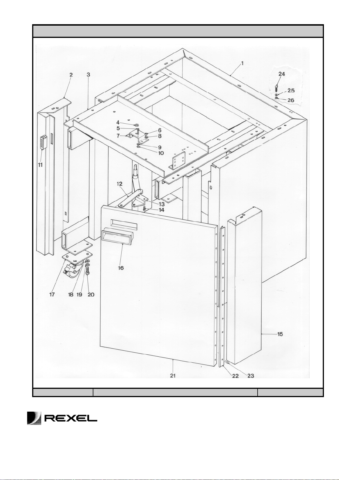
PAPER SHREDDER S16 SECTION 1
FRAME & COVER PANELS ASSEMBLY
NO PART NO DESCRIPTION QTY COMMENTS
1 25384 REAR COVER PANEL 1
2 25400 LH FRONT COVER PANEL ASSY 1
3 A25065 FRAME ASSEMBLY 1
4 TRU67 GRIP RING 1
5 SCM43 M3 X 20 POZI PAN SCREW 2
6 NM8 M5 NUT 4
7 25238 SAFETY SWITCH BRACKET 1
8 SHK3 M5 SHAKEPROOF WASHER 8
9 SHK1 M3 SHAKEPROOF WASHER 4
10 NM7 M3 NUT 2
11 SL23-12 DOOR CATCH MAGNET 1
12 25418 LINKAGE ASSEMBLY 1
13 25244 LINKAGE BRACKET 1
14 SCM40 M5 X 12 POZI HEAD SCREW 4
15 D25398 RH FRONT COVER PANEL ASSY 1
16 SL18-281 HANDLE 1
17 SL18-184 LOCKING CASTOR 2
SL18-297 NON-LOCKING CASTOR 2
18 PLN5 M8 PLAIN WASHER 16
19 SHK5 M8 SHAKEPROOF WASHER 16
20 SCM38 M8 x 16 HEX HEAD SCREW 16
21 D25402 DOOR ASSEMBLY 1
22 25419 HINGE 1
23 RTS37 POP RIVET 20
24 SCM15 M6 x 12 SCREW HEX HEAD 11
25 PLN4 M6 PLAIN WASHER 11
26 SHK4 M6 SHAKEPROOF WASHER 11
ISSUE 2
PAPER SHREDDER S16 SECTION 1
ILLUSTRATED PARTS LIST
DEM Page 6 of 43 FEBRUARY 07
FRAME & COVER PANELS ASSEMBLY
ISSUE 2
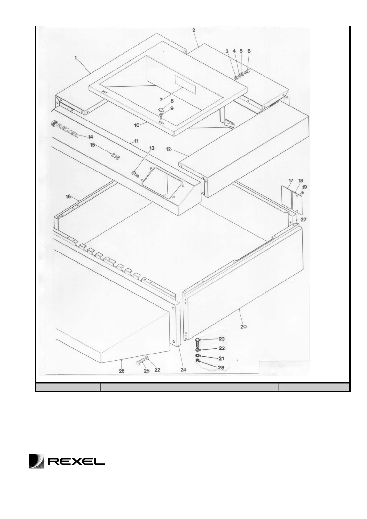
PAPER SHREDDER S16 SECTION 2
ILLUSTRATED PARTS LIST
CASING ASSEMBLY
DEM Page 7 of 43 FEBRUARY 07
NO PART
DESCRIPTION QTY COMMENTS
NO
25467 TOP COVER ASSY COMPLETE 1 Consists of Item Nos.
1 25397 SIDE PANEL UPPER CASE LH 1
2 25396 REAR PANEL UPPER CASE 1
3 NM8 M5 HEXAGON NUT 2
4 SHK3 M5 SHAKEPROOF WASHER 2
5 PLN3 M5 PLAIN WASHER 2
6 39019 LOCATING PEG 2
7 D000309 OILING/WARNING DECAL 1
8 45659 PLASTIC CAP 2
9 SCM122 M5 x 20 SOCKET CAP SCREW 2
10 A25434 FEED CHUTE 1
11 25394 FACIA PANEL 1
12 25080 SIDE PANEL UPPER CASE RH 1
13 SCM81? M4 x 12 COUNTERSUNK RAISED
HEAD SCREW
14 1000748 REXEL LOGO DECAL 1
15 D000238? FACIA DECAL 1
16 25072 SIDE PANEL CASE LH 1
17 D000157 ? INSTRUCTION DECAL 1
18 RPS16 RATING PLATE 1
19 RTS19 POP RIVET 2
20 25073 SIDE PANEL CASE RH 1
21 PLN4 M6 PLAIN WASHER 4
22 SHK4 M6 SHAKEPROOF WASHER 8
23 SCM13? M6 x 40 HEXAGON HEAD SCREW 4
24 25143 FRONT PANEL CASE S/W ASSY 1
25 SCM31 M6 x 30 HEXAGON HEAD SCREW 4
26 25094 FEED SHELF 1
27 25075 REAR PANEL 1
28 NM5 M6 HEXAGONAL NUT 4
ISSUE 2
PAPER SHREDDER S16 SECTION 2
ILLUSTRATED PARTS LIST
CASING ASSEMBLY
4
DEM Page 8 of 43 FEBRUARY 07
ISSUE 2
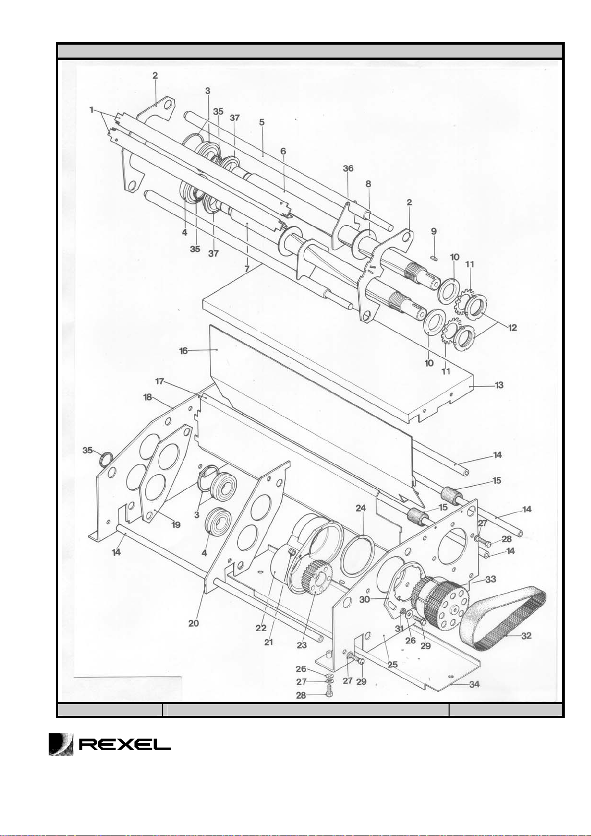
PAPER SHREDDER S16 SECTION 3
ILLUSTRATED PARTS LIST
CUTTING HEAD
DEM Page 9 of 43 FEBRUARY 07
NO PART
DESCRIPTION QTY COMMENTS
NO
25449 CUTTING HEAD COMPLETE 1 Comprising Item Nos.
1 D25435 INFEED EXTENSION 1 2
2 D25440 PAPER GUIDE 2 UP TO S/N 661559
3
4 BR15 BEARING 2
5 D25443 STRIPPER BAR 2
6 D25445 CUTTER DRIVE SHAFT 1
7 D25446 CUTTER DRIVEN SHAFT 1
8 D25437 CUTTER 268
9 KEY31? KEY 8 x 7 x 18 (ROUND ONE END) 2
10 D25444 COLLAR 2
11 TAB5 TAB WASHER 40 2
12 NM29 NUT NOTCHED M40 x 1.5 2
13 D25436 MOT O R DUST COVER 1
14 45966 TIE ROD 4
15 45535 SUPPORT BUSH 2 NOLONGER FITTED
16 D25427 BIN FULL FLAP 1
17 D25448 DEFLECTOR PLATE 1
18 A25429 SIDE PLATE LH ASSEMBLY 1 COMPRISING
19 D25439BI STRIPPER LOCATION PLATE LH 1
20 D25438 STRIPPER LOCATION PLATE RH 1
21 NM22 NUT NYLOC M8 2
22 D25442 GEARBOX COVER 1
23 45737 2ndSTAGE PLANET CARRIER 1
24 TRU84 GEAR CASING CIRCLIP 1
25 A25428 SIDE PLATE RH ASSEMBLY 1 COMPRISING
26 PLN5/L WASHER PLAIN 6
27 SHK5 SHAKEPROOF WASHER 16
28 SCM32 M8 x 20 HEX HEAD SCREW 8
29 SCM38 M8 x 16 HEX HEAD SCREW 10
30 45541 DE-JAM KICK PLATE 1
31 45539BI SPACER 2
32 SL22-82 BELT 1
33 45667 GEARBOX COMPLETE 1
34 D25441 REAR HEAD SUPPORT PANEL 1
35 TRU70 CIRCLIPS 3
36 D45973 STRIPPERS 268
37 45585 COLLARS 2
D25454
BR22
PAPER GUIDE
BEARING C/W SNAP RING
2
2
FROM S/N 661559
ISSUE 2
PAPER SHREDDER S16 SECTION 3
ILLUSTRATED PARTS LIST
DEM Page 10 of 43 FEBRUARY 07
CUTTING HEAD
ISSUE 2
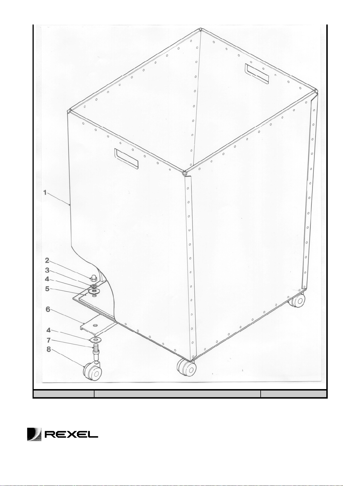
PAPER SHREDDER S16 SECTION 4
ILLUSTRATED PARTS LIST
BIN ASSEMBLY
DEM Page 11 of 43 FEBRUARY 07
NO PART
DESCRIPTION QTY COMMENTS
NO
1 25386 FIBRE BIN 1
2 D-NUT36 M8 DOME NUT 4
3 SHK5 M8 SHAKEPROOF WASHER 4
4 PLN27 WASHER LARGE 8
5 25452 BASE REINFORCEMENT 1
6 25413 BASE STIFFENER 2
7 SL18-344 CASTOR STEM INSERT (M8 x 15) 4
8 SL18-345 CASTOR 4
ISSUE 2
PAPER SHREDDER S16 SECTION 4
ILLUSTRATED PARTS LIST
BIN ASSEMBLY
DEM Page 12 of 43 FEBRUARY 07
ISSUE 2
PAPER SHREDDER S16 SECTION 5
ILLUSTRATED PARTS LIST
ELECTRICS
DEM Page 13 of 43 FEBRUARY 07

NO PART
DESCRIPTION QTY COMMENTS
NO
25455 SWITCH/CONTROL UNIT
COMPLETE
1 NM7 NUT M3 2
2 SKH1 SHAKEPROOF WASHER 6
3 SL8-107 MICROSWITCH 1
4 SCM78 SCREW M3 x 16mm POZI PAN 4
5 SL6-33 CAPACITOR 90-112uF 1 TO S/N 690498
6 NM5 NUT M6 2
7 SHK4 SHAKEPROOF WASHER 2
8 PLN4 PLAIN WASHER 2
9 SCM87 SCREW M6 x 16mm 2
10 SL6-22 CAPACITOR 16uF 1 TO S/N 930900
SL6-53 CAPACITOR 15uF 1 FROM S/N 930900
11 PEG6 PIN 30 x 5mm 1
12 SL26-10 MOTOR FAN 1
13 SL20-255 MOTOR 600W 220-240V 1 C/W CAPACITORS (2) UP TO S/N 690498
SL20-265 MOTOR 600W 220-240V 50Hz 1 FROM S/N 690498 TO S/N 930900
SL20-309 MOTOR 600W 220-240V 50Hz 1 FROM S/N 930900
14 SHK6 SHAKEPROOF WASHER M8 4
15 SCM38 SCREW M8 x 16mm HEX HEAD 4
16 KEY 1 KEY 5 x 5 x 40mm 1
17 SCM27 SOCKET SET SCREW M5 x 10mm 1
18 45621 MOTOR PULLEY 1
19 SL9-11 6-WAY TERMINAL BLOCK 1 T O S/N 930900
20 SCM43 SCREW M3 x 20mm POZI PAN 2 TO S/N 930900
21 NM13 NUT M3 PILLAR TYPE 4 TO S/N 930900
22 SL5-67 CONTACTOR 2 TO S/N 930900
SL5-80 CONTACTOR 115V 2
23 NM8 M5 NUT 8 TO S/N 930900
24 SHK3 SHAKEPROOF WASHER M5 8 TO S/N 930900
25 PLN3 PLAIN WASHER M5 8 TO S/N 930900
26 23516 INSULATION - SAFETY SWITCH 1
27 SL8-72 SAFETY SWITCH 1
28 SCM6? M4 x 30mm POZI PAN SCREW 2
29 SCR559B 2BA x 1” BRASS SCREW 1
30 X1466 INSULATION 2 TO S/N 930900
31 SL9-19 16A TERMINAL BLOCK 1 TO S/N 930900
32 SL5-69 MECHANICAL INTERLOCK 1 TO S/N 930900?
33 V2132/1 EARTH TAG 1 TO S/N 930900
34 NUT 42B 2BA BRASS NUT 3
35 SL17-41 SHELL CLAMP 4 T O S/N 930900
36 PLN3B 2BA PLAIN BRASS WASHER 3
37 SL17-131? BAR CLAMP 2
38 SHK2? SHAKEPROOF WASHER M4 1
39 NM3? M4 NUT 1
40 SL4-28 CABLE 1 T O S/N 930900
SL4-29 CABLE 115V 1 T O S/N 930900
41 SL17-112 SELF-ADHESIVE CABLE CLIP 3 TO S/N 930900
SL17-111 SELF-ADHESIVE CABLE CLIP 3 FROM S/N 930900
42 SL17-126 CABLE ENTRY CLAMP 1 TO S/N 930900
43 SL17-127 ENTRY CLAMP BUSH 1 TO S/N 930900
44 SCM22 SCREW M6 x 20mm HEX HEAD 1 TO S/N 930900
ISSUE 2
PAPER SHREDDER S16 SECTION 5
ILLUSTRATED PARTS LIST
ELECTRICS
1
DEM Page 14 of 43 FEBRUARY 07

ISSUE 2
PAPER SHREDDER S16 SECTION 5
ILLUSTRATED PARTS
LIST
ELECTRICS
DEM Page 15 of 43 FEBRUARY 07

NO PART
DESCRIPTION QTY COMMENTS
NO
45 D000200 CONTROL PANEL DECAL 1 T O S/N 930900
1000728 S16 SWITCH DECAL 1 FROM S/N 930900
46 SL10-45 RED NEON INDICATOR LIGHT 1
SL10-62 RED NEON LIGHT 115V 1
47 SL10-46 RED LED INDICATOR LIGHT 1 TO S/N 930900
48 SL8-117 EMERGENCY STOP SWITCH 1
49 SCM81 M4 x 12mm COUNTERSUNK
RAISED HEAD SCREW
50 25350 SWITCH BRACKET S/W ASSY 1
51 SL17-147 SWITCH PANEL 1 TO 23/12/94
SL17-242 SWITCH PCB 1 FROM 2/1/95 TO S/N 930900
SL17-319 SWITCH PCB 1 FROM S/N 930900
52 SL8-118 SWITCH MOUNTING CONNECTOR 1
53 SL8-119 DP CONTACTOR BLOCK 1
54 W142 WIRING KIT 1 TO S/N 930900
W159 WIRING KIT 115V 1
WD283 WIRING DIAGRAM 1 TO S/N 930900
WD294 WIRING DIAGRAM 1 FROM S/N 930900
55 SL17-143 PCB LUG SUPPORT 4
56 25290 PCB BRACKET S/W ASSEMBLY 1 TO S/N 930900
SL17-320 PCB PILLAR 1 FROM S/N 930900
SL17-321 PCB PILLAR 3 FROM S/N 930900
57 SL17-182 CONTROL PCB 1 TO 23/12/94
SL17-243 CONTROL PCB 1 FROM 2/1/95 TO S/N 930900
SL17-238 CONTROL PCB 115V 1
SL17-318 CONTROL LED PCB 1 FROM S/N 930900
58 SL18-198 CABLE CLAMP 2
59 SCR543 NO.6 x ¼” POZI PAN (TYPE Z) 2
60 1000880 INLET SOCKET BRACKET 1 FROM S/N 930900 (NOT SHOWN)
61 SL12-51 APPLIANCE INLET SOCKET 1 FROM S/N 930900 (NOT SHOWN)
62 SL15-22 10 AMP FUSE SEMI DELAY 1 FROM S/N 930900 (NOT SHOWN)
63 1000762 SAFETY CICUIT 1 FROM S/N 930900 (NOT SHOWN)
4
ISSUE 2
PAPER SHREDDER S16 SECTION 1
SERVICE INSTRUCTIONS
DEM Page 16 of 43 FEBRUARY 07

INSTALLATION NOTES
POWER SUPPLY
Check that the details marked on the machine rating plate conform with the electrical mains supply.
Single phase power supply operation - 115v. 1ph. 60Hz
240v. 1ph. 50Hz
This machine must be earthed.
SAFETY PRECAUTIONS
1. Before ‘testing’ or ‘using’ the machine, the locking castor wheels MUST be securely locked in the
LOCKED POSITION; this is achieved by depressing the locking levers on the two castor wheels
at the front of the machine. When the castor wheels are securely locked the machine is prevented
from moving on the floor in the event of the paper cutters becoming jammed.
2. DISCONNECT the electrical mains supply plug from its socket before commencing any services.
3. PAT TEST after any servicing.
NOTE: THE ELECTRIC MOTOR IS PROTECTED BY AN AUTOMATIC OVERLOAD CUTOUT.
PAPER SHREDDER S16 SECTION 2
SERVICE INSTRUCTIONS
DEM Page 17 of 43 FEBRUARY 07

LUBRICATION OF CUTTING HEAD
To avoid a build-up of paper dust, the cutting head should be cleaned thoroughly on a regular basis
followed by the application of a small amount of shredder oil to lubricate the cutters. Oil penetration
can be assisted by running the machine in reverse and forward modes alternatively.
When the machine is used regularly it is recommended that cleaning and oiling is carried out at
weekly intervals.
At six monthly intervals chains, sprockets and gears should be cleaned and re-coated with Rexel
Shredder Oil.
DEM Page 18 of 43 FEBRUARY 07

PAPER SHREDDER S16 SECTION 3
SERVICE INSTRUCTIONS
FEED CHUTE REMOVAL AND REPLACEMENT
1. Remove the two plastic screw covers (1, fig. 1) by prising upwards with s screwdriver.
2. Remove the two set screws (2, fig. 1), lift front of feed chute, slide forward to unplug at the rear
and lift free.
3. Assemble in reverse sequence.
4. NOTE: if replacing feed chute the two plugs (3, fig.1) can be removed and refitted to a new feed
chute by removal of nuts and washers (4,5,6, fig.1).
DEM Page 19 of 43 FEBRUARY 07

PAPER SHREDDER S16 SECTION 4
SERVICE INSTRUCTIONS
REMOVAL OF CASING
1. Remove the four screws (1, fig. 2), securing the operating switches assembly to facia
panel.
2. Lower the switch assembly to the inside of the machine.
3. Open the hinged door and withdraw the waste bin (1, fig.3).
4. Remove the four nuts and washers (1, fig.4) securing the casing to the frame assembly.
These are situated within the main frame, upper section.
PAPER SHREDDER S16 SECTION 4
SERVICE INSTRUCTIONS
5. Remove the casing from the main frame assembly (2, fig.4).
6. Assemble in reverse sequence.
DEM Page 20 of 43 FEBRUARY 07

DEM Page 21 of 43 FEBRUARY 07

PAPER SHREDDER S16 SECTION 5
CUTTING HEAD ADJUSTMENT
Ensure that machine is disconnected from the electricity supply.
Too much clearance between adjacent cutters can cause incorrect shredding.
To rectify:-
1. Remove the casing (section 2 page 4).
2. Prose open locking washers on both shafts on the gearbox end.
3. Tighten locknuts equally to a finger tight position using a ‘C’ spanner or by pushing on
notches with a screwdriver.
SERVICE INSTRUCTIONS
4. Peen over locking tabs on to locknuts to secure in position.
5. Run amchine and test for quality of cut.
6. If cut quality is unacceptable repeat stages 2-5 and tighten lock nuts equally in one notch
steps until an accceptable quality of cut is obtained.
7. Refit casing and test operation.
DEM Page 22 of 43 FEBRUARY 07

PAPER SHREDDER S16 SECTION 6
SERVICE INSTRUCTIONS
REPLACING DRIVE BELT
1. Remove the casing (section 2, page 4).
2. NOTE: The gearbox pulley and motor drive are on fixed centres. To remove belt, slaken
socket set screw securing motor pulley and wind belt off gearbox pulley as shown (fig. 5).
3. to fit replacement belt, position motor pulley half way onto motor shaft. Fit belt and ‘wind’
onto gearbox pulley.
4. Align motor pulley with gearbox and secure with grub screw.
5. Refit cover and test.
DEM Page 23 of 43 FEBRUARY 07

PAPER SHREDDER S16 SECTION 7
SERVICE INSTRUCTIONS
REPLACING CUTTING HEAD
1. Remove the casing (section 2, page 4).
2. Remove the motor dust cover and lift out the bin full flap.
3. Note and disconnect motor wires from the rear terminal block, capacitor and earth screw.
Disconnect the wires from the bin full switch.
4. Remove the drive belt (section 2, page 6) and motor (section 2, page 12).
5. Unscrew 4 cutting head fixing screws and lift out the cutting head assembly. NOTE: 4
holes are provided in the sideplates for lifting with a hoist if required.
6. Replace the new cutting head assembly and reassemble in the reverse sequence.
7. Test the operation and adjust the cutter tension if necessary.
DEM Page 24 of 43 FEBRUARY 07

PAPER SHREDDER S16 SECTION 8
SERVICE INSTRUCTIONS
REPLACING GEARBOX
1. Remove the cutting head unit (section 2 page 7), drive belt (section 2 page 6), and motor
(section 2 page 10).
2. Support the cutting head with the gearbox uppermost and remove the screws securing the
de-jam plate, gearbox cover and tie rods. Lift away the side plate and gearbox assembly.
(Fig 6)
3. Remove the circlip securing the gearbox and withdraw the gearbox from the side frame.
Retain the de-jam plate.
4. On separation of the gearbox, part of the gear train may remain in the gearbox position.
Remove the gears and clean gearbox cover.
NOTE: Examine the shaft bearings and 1/1 gears for wear and replace if required.
5. Should the gears have become dislodged from the replacement gearbox position the
centre dowel gear as shown (fig. 7) into drive pulley, locate the centre dowel and engage
assembled 1st stage gear. Pack with LM2 grease. Engage the assembled 2nd stage
planet gear carrier with the 1st stage drive gear.
Restrain the gear carrier and rotate the drive pulley to seat the gears.
6. Align the de-jam plate with the gear casing and secure with the new circlip to the side
frame.
7. Offer the side frame assembly to the gearbox cover and rotate the drive pulley to locate
the gears.
8. Locate the de-jam plate with the gearbox mounting holes and secure.
9. Reassemble the remaining components in the reverse sequence.
DEM Page 25 of 43 FEBRUARY 07

PAPER SHREDDER S16 SECTION 8
SERVICE INSTRUCTIONS
REPLACING GEARBOX CONT’D
DEM Page 26 of 43 FEBRUARY 07

PAPER SHREDDER S16 SECTION 9
SERVICE INSTRUCTIONS
CUTTERS AND STRIPPER REPLACEMENT
1. Remove the cutting head (section 2, page 7) and gearbox and sideframe assembly
(section 2 page 8).
2. Remove the 1/1 gears and gearbox cover assembly.
3. Prise open the locking washers and unscrew the locknuts on both shafts. Remove the
collars from both shafts and lift away the paper guide plate and infeed extensions.
4. NOTE
: The assembly order of cutter s and stripper and remove cutters and strippers as
required.
5. Reassemble the new cutters and stripper onto the shafts in the original order of assembly
(i.e in stacks of 4 components).
6. Reassemble the cutting head and test the operation.
7. Adjust the cutter clearance (section 2 page ) as necessary to give a good quality cut.
DEM Page 27 of 43 FEBRUARY 07

PAPER SHREDDER S16 SECTION 10
SERVICE INSTRUCTIONS
MOTOR REPLACEMENT
1. Remove the casing (section 2 page 4), the motor dust guard and the bin full flap.
2. Remove the drive belt and motor pulley (section 2 page 6).
3. Note the wiring connections and disconnect the motor wires from the terminal block,
capacitor and the motor earth screw.
4. Remove the screws securing the motor to the side frame.
5. Lift away the motor and fit the replacement, ensuring that the details on the motor rating
plate are correct for the machine.
6. Reconnect motor wires as originally fitted and reassemble the machine.
7. Run the machine and test the operation.
NOTE: Should the motor operate in reverse on test, interchange the black and
red motor wires.
DEM Page 28 of 43 FEBRUARY 07

PAPER SHREDDER S16 SECTION 11
SERVICE INSTRUCTIONS
SWITCH PANEL REPLACEMENT
1. Remove the casing (section 2 page 4).
2. Disconnect the ten way ribbon plug from the PCB (1, fig.9).
3. Note the wiring connections and disconnect the four wires (2, fig.9) from the emergency
stop switch.
4. Replace with the new switch panel and reconnect the wires as originally fitted (refer to
WD221, fig.9A).
5. Reassemble the machine in the reverse sequence.
6. Run the machine and test the operation.
DEM Page 29 of 43 FEBRUARY 07
Fig 9
Fig 9a

PAPER SHREDDER S16 SECTION 12
SERVICE INSTRUCTIONS
ELECTRONIC ADJUSTMENTS (REED SWITCHES)
Two sensors are mounted on the printed circuit board (PCB) 91, fig.11), each of which
comprise a coil supported on a terminal block and encircling a reed switch. One sensor
detects the high current present in the event of a phase failure, the other detecting the high
current drawn when the motor stalls due to the jamming of the cutting head. The magnetic
field from the coils operates the reed switches that form part of the logic circuit controlling the
contactors which directly switch the motor. (Warning: the glass encapsulated reed switch is
fragile). In the event of a phase failure, the machine will cease to operate, and the control
‘STOP’ button will illuminate.
When jamming occurs, after a short pause, the motor will automatically reverse momentarily
and then stop, the unshredded paper having been returned to the feed chute. The
illuminated controls will now indicate the ‘STOP’ mode. Manual reverse can be obtained by
pressing the reverse button on the control panel to give momentary reverse and then stop.
The waste container door is linked to a safety switch which is connected in the logic circuit
and when open also reverts the machine to the ‘[STOP’ mode. This condition is indicated by
an illumination on the switch control panel/
A ‘Fail-Safe’ circuit is incorporated within the logic circuit to detect any interruption in the
power supply which causes the machine to suddenly cease working. When the power
supply is restored the machine will automatically be re-set into the ‘STOP’ mode.
Machine not cutting required number of sheets
to establish whether the fault is mechanical or electrical both sensors on the PCB should be
temporarily short circuited as in fig.10. The machine should now be checked on mechanical
setting for maximum number of sheets cut and, if satisfactory, will indicate that the fault is
electronic, and adjustment is required. During the test avoid stalling the motor for a
prolonged period. If the maximum cut is not satisfactory, the problem is mechanical.
Adjustment
Revert the sensor connections to the original circuit before proceeding. Correct adjustment is
attained by slackening the terminal block securing screw(1,fig 11) and slightly rotating the
block to adjust the position of the coil relative to the reed switch (2, fig 11). Adjustment of the
coil towards either end of the switch will increase the quantity of sheets cut. Returning the
coil towards the centre decreases the quantity. When the coil is set, tighten the terminal
block securing screw.
This is the only adjustment on the PCB, should any other problems be encountered with the
electronics the complete PCB should be replaced.
ELECTRONIC ADJUSTMENTS (REED SWITCHES) CONT’D
DEM Page 30 of 43 FEBRUARY 07

PAPER SHREDDER S16 SECTION12
PAPER SHREDDER S16 SECTION 13
SERVICE INSTRUCTIONS
SERVICE INSTRUCTIONS
ELECTRONIC ADJUSTMENTS (SENSING COILS)
DEM Page 31 of 43 FEBRUARY 07

The sensor is mounted on the printed circuit board (PCB) (fig 11b) and detects the high
current drawn when the motor stalls due to the cutting head jamming. The magnetic field of
the wire passing through the coil is sensed by the coil and operates the potentiometer, which
forms part of the logic circuit controlling the contactors which switch the motor.
When jamming occurs, after a short pause, the motor will automatically reverse momentarily
and then stop; the unshredded paper having been returned to the feed chute. The
illuminated controls will now indicate the “STOP” mode. Manual reverse can be obtained by
pressing the reverse button on the control panel to give momentary reverse and then stop.
The waste container door is linked to a safety switch which is connected in the logic circuit
and when open also reverts the machine to the “STOP” mode. This condition is indicated by
an illuminated on the switch control panel.
A “Fail-Safe” circuit is incorporated within the logic circuit, to detect any interruption in the
power supply that may cause the machine to suddenly cease working. When the power
supply is restored the machine will automatically be reset into the “STOP” mode.
Machine Not Cutting the Required Number of Sheets
Each machine is set at the factory to achieve the cutting of the maximum number of sheets.
The electrical control is achieved by setting the potentiometer on the PCB (fig 11b). The
electrical setting is checked using the 2-pin test plug located by the potentiometer and
checking the electrical resistance (ohms); compare the value with the factory setting value.
N.B. The setting screw located on the top of the potentiometer is used to achieve adjustment
if necessary. Turning the screw clockwise will increase the maximum number of sheets cut.
Should any other problems be encountered with the electronics, the complete PCB should be
replaced.
PAPER SHREDDER S16 SECTION 14
SERVICE INSTRUCTIONS
DEM Page 32 of 43 FEBRUARY 07

PAPER SHREDDER S16 SECTION 15
PRINTED CIRCUIT BOARD REPLACEMENT – REED SWITCH
1. Remove casing (ref section 3)
2. Note wiring connections and disconnect the two wires from the terminal block on the
PCB (1, fig 12).
3. Disconnect the 8-way plug (2, fig 12) and the 10-way ribbon plug (3, fig 12) from the
PCB.
4. Remove the PCB from its support and replace with the new board.
5. Reconnect wires and plugs as originally fitted (refer to wiring diagram).
6. Reassemble machine in reverse sequence. Carry out PAT test, run machine and test
operation.
SERVICE INSTRUCTIONS
DEM Page 33 of 43 FEBRUARY 07

PRINTED CIRCUIT BOARD REPLACEMENT – SENSING
COIL
1. Remove casing (ref section 3)
2. Note wiring connections and disconnect at the (7 Connectors) terminal block on the
PCB
3. Disconnect the 10-way ribbon plug from the PCB.
4. Disconnect the Over Current Wire from the Auto Reset Switch and remove from the
centre of the Over Current Coil.
5. Remove the PCB from its support and replace with the new board.
6. Reconnect wires and plugs as originally fitted (refer to wiring diagrams).
7. Reassemble the machine in the reverse sequence. Carry out PAT test, run the
machine and test the operation.
PAPER SHREDDER S16 SECTION 16
SERVICE INSTRUCTIONS
CONTACTOR REPLACEMENT
DEM Page 34 of 43 FEBRUARY 07

1. Remove casing (ref section 3).
2. Note wiring connections and disconnect all wires from
contactor(s) to be replaced (1, fig 13).
3. Remove the eight screws, nuts and washers (2, fig 13) securing both contactors to the
main frame.
4. Remove the mechanical interlock clips from between the two contactors using pliers,
separate the contactors and remove the mechanical interlock unit (3,fig 13).
5. Replace the contactor(s) as required and reassemble the mechanical interlock and
clips.
6. Reconnect wiring as originally fitted (refer to wiring diagrams).
7. Reassemble machine in reverse sequence. Run machine and test for operation.
PAPER SHREDDER S16 SECTION 17
SERVICE INSTRUCTIONS
DEM Page 35 of 43 FEBRUARY 07

HINGED GATE SAFETY SWITCH REPLACEMENT
1. Remove casing (section 3).
2. Remove the four screws, nuts and washers (1, fig 14) securing the switch bracket to
the main frame.
3. Remove the switch and bracket assembly ( 2, fig 14) and also the shaft support
bracket (3, fig 14).
4. Separate the switch and insulating cover from the bracket by removing the two screws
and nuts (4, fig 14).
5. Disconnect the leads from the switch.
6. Replace with new switch and connect the wiring.
7. Assemble in reverse sequence and test operation.
PAPER SHREDDER S16 SECTION 18
SERVICE INSTRUCTIONS
DEM Page 36 of 43 FEBRUARY 07

BIN FULL SWITCH REPLACEMENT
1. Remove casing (section 3).
2. Disconnect switch from the switch located on the left hand side frame.
3. Remove the two screws securing switch and insulating cover to bracket.
4. Replace with the new switch and reconnect the wiring. Test operation.
5. Assemble in reverse sequence.
DEM Page 37 of 43 FEBRUARY 07

PAPER SHREDDER S16 SECTION 19
FACTORY POTENTIOMETER SETTINGS
All machines are set in the factory to achieve the maximum number of sheets
cut by adjusting the potentiometer to the value shown below.
Individual machines may require adjustment to suit the site conditions, by either
increasing or decreasing the resistance value as required.
MACHINE
SUPPLY RESISTANCE (k ohm)
S16 230V 50HZ 950
S16 115V 60Hz 500-600
These values are for reference only and are not intended to represent the
values required by an individual machine site.
SPECIFICATION
MODEL S16
Power Supply 220-240V 50 Hz
Height 1170 mm
Width 735 mm
Depth
With shelf
Weight 140Kg
Motor Power 600W
Particle Size 6 mm Strip
Speed 12 m/min
Max Sheets (A4 70gsm) 40
660 mm
980 mm
Dimensions of Waste Container (HxDxW) 715 x 510 x 600 mm
Waste Container Capacity 0.205 m3
DEM Page 38 of 43 FEBRUARY 07

PAPER SHREDDER S16 SECTION 20
WIRING DIAGRAMS
Wiring Diagram 115V with Sensing Coil
DEM Page 39 of 43 FEBRUARY 07

PAPER SHREDDER S16 SECTION 20 CONT’D
WIRING DIAGRAMS
Wiring Diagram 220-240V with Sensing Coil
( From 2/1/95 S/N 690488 To S/N 930900)
DEM Page 40 of 43 FEBRUARY 07

PAPER SHREDDER S16 SECTION 20 CONT’D
WIRING DIAGRAMS
Wiring Diagram 220-240V with Reed Switch
(To 23/12/94 S/N 690488)
PAPER SHREDDER S16 SECTION 20 CONT’D
DEM Page 41 of 43 FEBRUARY 07

SERVICE INSTRUCTIONS
WIRING DIAGRAMS
Wiring Diagram 220-240V
( From S/N 930900)
DEM Page 42 of 43 FEBRUARY 07

PAPER SHREDDER S16
AMENDMENT RECORD SHEET
ISSUE
NO
DECRIPTION SERIAL
NO
CARO NO
1 Original - 2 PCB with sensing coil and new motor 690488
3 LED PCB and new motor 930900
DEM Page 43 of 43 FEBRUARY 07
 Loading...