

Page 1

Copyright and Warranty Notice
The information in this document is subject to change without notice and does not
represent a commitment on part of the vendor, who assumes no liability or
responsibility for any errors that may appear in this manual.
No warranty or representation, either expressed or implied, is made with respect to
the quality, accuracy or fitness for any particular part of this document. In no event
shall the manufacturer be liable for direct, indirect, special, incidental or
consequential damages arising from any defect or error in this manual or product.
Product names appearing in this manual are for identification purpose only and
trademarks and product names or brand names appearing in this document are
property of their respective owners.
This document contains materials protected under International Copyright Laws. All
rights reserved. No part of this manual may be reproduced, transmitted or
transcribed without the expressed written permission of the manufacturer and
authors of this manual.
If you do not properly set the motherboard settings causing the motherboard to
malfuncti on or f ail, we cannot guaran t e e an y responsibil it y.
Page 2

Page 3

BE6-II Motherboard User’s Manual
Table of Contents
CHAPTER 1. INTRODUCTION OF BE6-II FEATURES 1-1
EATURES OF THIS MOTHERBOARD
1-1. F
PECIFICATIONS
1-2. S
1-3. L
1-4. T
AY OU T DIAGRAM
HE SYSTEM BLOCK DIAGRAM
CHAPTER 2. INSTALLING THE MOTHERBOARD 2-1
NSTALLING THE MOTHERBOARD TO THE CHASSIS
2-1. I
NSTALLATION OF THE PENTIUM
2-2. I
NSTALLING SYSTEM MEMORY
2-3. I
2-4. C
2-5. CPU
ONNECTORS
FREQUENCY SETTINGS
, H
EADERS AND SWITCHES
II/III, C
ELERONTM
CPU 2-3
CHAPTER 3. INTRODUCTION OF THE BIOS 3-1
OFTMENU
3-1. S
TAN DAR D
3-2. S
3-3. A
3-4. A
3-5. I
3-6. P
3-7. P
3-8. PC H
3-9. L
3-10. L
3-11. S
3-12. S
3-13. E
DVANCED
DVANCED CHIPSET FEATURES SETUP MENU
NTEGRATED PERIPHERALS
OWER MANAGEMENT SETUP MENU
N
P/PCI C
OAD FAIL-SAFE DEFAULTS
OAD OPTIMIZED DEFAULTS
ET PASSWORD
AV E
XIT WITHOUT SAV I N G
ONFIGURATIONS
EALTH STATUS
XIT SETUP
& E
™ III S
CMOS F
BIOS F
ETUP
EATURES SETUP MENU
EATURES SETUP MENU
1-1
1-2
1-5
1-6
2-2
2-3
2-6
2-19
3-4
3-9
3-14
3-20
3-24
3-29
3-37
3-42
3-43
3-43
3-44
3-45
3-46
MN-171-2A2-71 Rev. 1.02
Page 4

APPENDIX A BIOS FLASHING USER INSTRUCTIONS
APPENDIX B INSTALLING THE HIGHPOINT XSTORE PRO
UTILITY
APPENDIX C HARDWARE MONITORING FUNCTION (INSTALLING
THE WINBOND HARDWARE DOCTOR UTILITY)
APPENDIX D INSTALLING THE DRIVER FOR ULTRA ATA/66
APPENDIX E THE THERMAL CABLE
APPENDIX F BX 133 OVERCLOCKING GUIDE
APPENDIX G HOW TO GET TECHNICAL SUPPORT
APPENDIX H TROUBLESHOOTING (NEED ASSISTANCE?)
Page 5

Introduction of BE6-II Features 1-1
Chapter 1. Introduction of BE6-II Features
1-1.Features of This Motherboard
The motherboard is designed for a new generation CPUs. It supports the Intel SLOT1
structure (Pen tium
II/III a nd Ce leron
TM
processors), up to 768MB of memory, super I/O,
and Green PC functions. The motherboard provides high performance for server systems
and meets the requirements for desktop system for mult imedia in the future.
The BE6-II has the HPT366 Ultra ATA/66 Chipset built-in. This means, the BE6-II will
support Ultra ATA/66 IDE devices. Ultra ATA/66 is the new standard for IDE devices. It
enhances existing Ultra ATA/33 technology by increasing both performance and data
integrity. This new high-speed i nterface doubl e s the Ultra ATA/33 bur st data transfer rate to
66.6 Mbytes/sec. The result is maximum disc performance using the current PCI local bus
environment. Another benefit is, you can connect another four IDE devices in your system
either Ultra ATA/33 IDE devices or Ultra ATA/66 IDE devices. You will have more
flexibility to expand your computer system.
The BE6-II has built-in hardware monitoring functions (you can refer to
Appendix C
for
detailed information), they can monitor and protect your computer insuring a safe
computing environment. The BE6-II also supports the PS/2 keyboard, PS/2 mouse,
password and hot key wake up features (you can refer to section 3-5 for detailed
information) , letti ng y ou e asily w ake up y our syste m by these devices . The mothe rboard can
provide high pe r f o r m ance for workstations and meets t he requirements f o r de sktop system s
for multimedia in the future.
The BE6-II uses the ABIT newest BIOS technology – CPU Soft Menu
CPU Soft Menu
TM
III technology not only lets you configure CPU settings easily but also
TM
III. The ABIT
lets you have a grea ter choice of C PU FSB clock setti ngs. It provides 12 0 different CPU
FSB clock settings . From 84 to 200 MHz, the increment for CPU FSB clock settings is
1Mhz by 1MHz (you can refer to section 3 -1 for det ailed information).
Sets Yo u Free From the Y2K Threat
The potential threat of Year 2000 (Y2K) problems are making everyone very nervous. The
Y2K issue applies to almost any device, firmware, or software that operates on or with year
based dates. This problem is caused by a design flaw in the Real Time Clock (RTC) unit.
The RTC only changes the last two digits of the yea r code, but not the century information.
As a result, when it comes to 12:00 AM January 1, 2000 the RTC will switch from
December 31 11:59 PM 1999 t o 12:00 AM January 1 1900.
User’s Manual
Page 6

1-2 Chapter1
Y2K compliance deals with the date change over from 31 December 1999 to 1 January 2000,
and with recording and reporting of all dates from the RTC including leap year dates. This
motherboard is free from the Y2K problem because its BIOS are Y2K compliant.
Please Note
If the operating system or application software cannot handle Year 2000 dates, you will
still be facing the Y2K threat because it is not a hardware problem that relates to the
motherboard itself. According to Award BIOS, it is BIOS source code released after 31
May 1995 complies with all known Y2K issues; however, it may still fail the 2000.exe
test. Award has modified its BIOS source code to accommodate the requirements of
2000.exe. Award BIOS source code issued later than 18 November 1996 passes the
NTSL 2000.exe test program.
1-2. Specifications
1. CPU
! Supports Intel Pentium III 450 ~ 800 MHz Processor cartridge.
! Supports Intel
! Supports Intel
! Supports 66 and 100MHz CPU external clock speeds
Pentium II 233 ~ 450 MHz Processor cartridge.
®
Celeron™ 266 ~ 533MHz processors (Based on 66MHz PPGA package)
2. Chipset
! Intel® 440BX chipset (82443BX and 82371EB)
! HPT366 Ultra DMA66 IDE controller supports four Ultra DMA66 devices
! Supports Ultra DMA/33 IDE protocol
! Supports Advanced Configuration and Power Management Interface (ACPI)
! Accelerated Graphics Port connector supports AGP 1x and 2x mode (Sideband) 3.3V
device
3. Memory (System Memory)
! Three 168-pin DIMM sockets support SDRAM modules
! Supports up to 768MB MAX. (8, 16, 32, 64, 128, 256 MB SDRAM)
! Supports ECC
4. System BIOS
! CPU SOFT MENU™ III, can easily set the processor parameters
! AWARD 6.0 Version BIOS
BE6-II
Page 7

Introduction of BE6-II Features 1-3
Supports Plug-and-Play (PnP)
!
Supports Advanced Configuration Power Interf ace (ACPI)
!
Supports Desktop Mana gem ent Interface (DMI)
!
Year 2000 compliant
!
5. Multi I/O Functions
2x Channels of Bus Master IDE Ports supporting up to four Ultra DMA 33/66 devices
!
2x Channels of Bus Master IDE Ports supporting up to four Ultra DMA 33 devices
!
PS/2 Keyboard and PS/2 Mouse Connectors
!
1x Floppy Port ( up to 2.88MB)
!
1x Parallel Port (EPP/ECP)
!
2x Serial Ports
!
2x USB Connectors
!
6. Miscellaneous
AT X form factor
!
One AGP slot, five PC I slots a nd one ISA slot
!
Supports PS/2 keyboard, PS/2 mouse, password and hot key wake-up functions
!
Built-in Wake on LAN header
!
Built-in IrDA TX/RX header
!
Built-in SB-Link
!
Built-in Wake On Ring header
!
Built-in two SMBus headers
!
Hardware monitoring:Included fan speed, voltages, CPU and system environment
!
temperature
One Thermal Sensor Cable i n cluded
!
Board size: 305 * 200mm
!
™
header
User’s Manual
Page 8

1-4 Chapter1
""""
Supports Wake On LAN, Keyboard or Mouse, but your ATX power supply 5V
standby power must be able to provide at least a 720mA current capacity.
Otherwise, the functions may not work normally.
""""
PCI slot 5 and HPT 366 IDE controller use the same bus master control signals.
""""
PCI slot 3 shares IRQ signals with the HPT366 IDE controller (Ultra ATA/66). The
driver for HPT 366 IDE controller supports IRQ sharing with other PCI devices.
But if you inst all a PCI card th at doe sn’ t a llo w IR Q sharin g with othe r de vi ces into
PCI slot 3, you may encounter some problems. Furthermore, if your Operating
System doesn’t allow peripheral devices to share IRQ signals with each other-Windows NT for example, you can’t install a PCI card into PCI slot 3.
""""
PCI slot 5 shares IRQ signals with the PCI slot 2
""""
HPT 366 IDE controller is designed to support high-speed mass storage. Thus we
don’t suggest you connect non-disk devices that use ATA/ATAPI interfaces, such as
CD-ROM to HPT 366 IDE connector (IDE3&IDE4).
Above 66MHz/100MHz bus speeds are supported but not guaranteed due to the PCI and
#
chipset specif ic ations.
Sound Blaster
#
States and certain other countries. Sound Blaster - LINK
™
is a registered trademark of Creative Technology Ltd. in the United
™
and SB-LINK™ are
trademarks of Creative Technology Ltd.
Specifications and information contained in this manual are subject to change without
#
notice.
Note
All brand names and trademarks are the property of their respective owners.
BE6-II
Page 9
Introduction of BE6-II Features 1-5
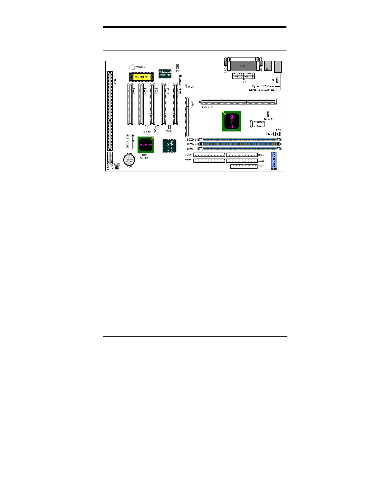
1-3. Layout Diagram
Figure 1-2. Motherboard component location
User’s Manual
Page 10
1-6 Chapter1
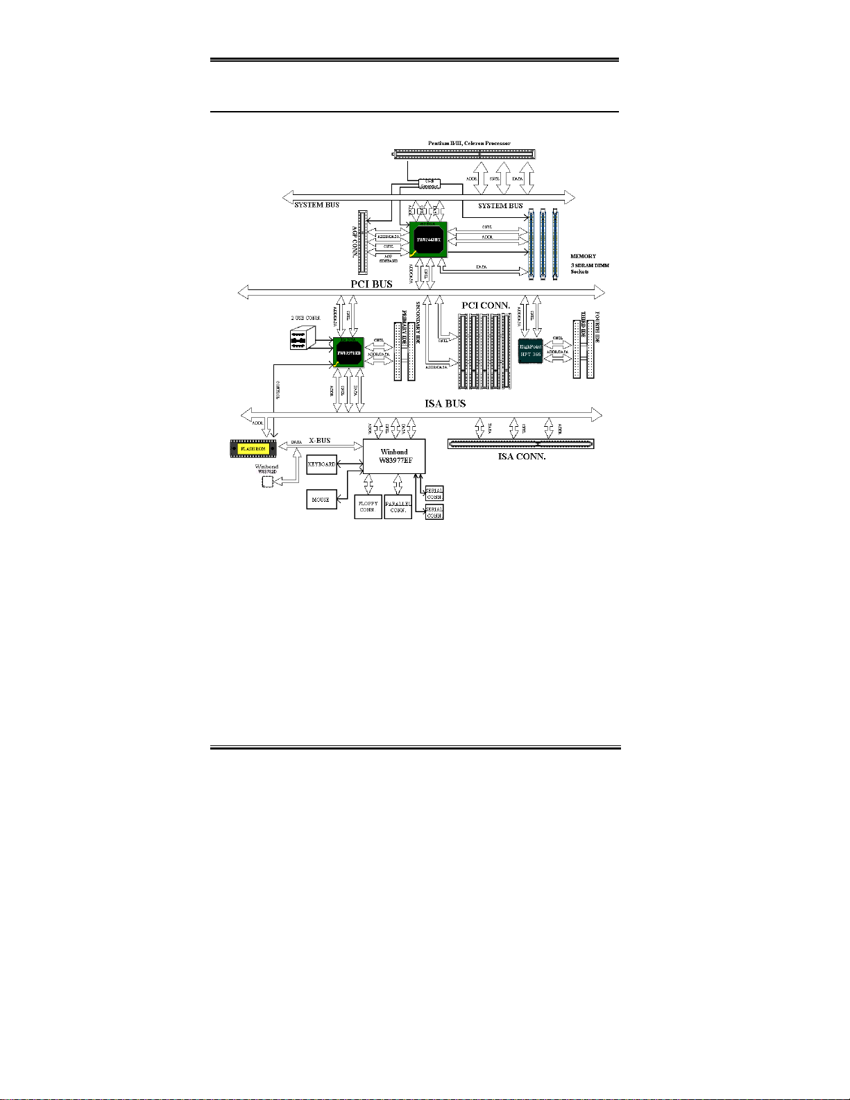
1-4. The System Block Diagram
BE6-II
Figure 1-3. System diagram of the 440BX chipset
Page 11

Installing the Motherboard 2-1
Chapter 2. Installing the Motherboard
This BE6-II motherboard not only provides all standard equipment for classic personal
computers, but also pr ovides great flexibilit y for meeting future upgrade dema nds. This
chapter will int roduce step by step all the stand ard equipment and will also presen t, as
completely as possible, future upgrade capabilities. This motherboard is able to support all
Intel
Pentium II/III processors and Intel Celeron processor now on th e market. (For
details, see specifications in Chapter 1.)
This chapter is organized according the following features:
2-1 Installing the Motherboard to the Chassis
2-2 Installati on of the Pentium
2-3 Installing System Memory
2-4 Connectors, Headers and Switches
2-5 CPU Frequency Settings
$$$$
$$$$
$$$$$$$$
Before you install or un plug any connect ors or add-on card s, please remember t o turn the
ATX power supply switch off (fully turn the +5V standby power off), or take the power cord
off. Otherwise, you may cause the motherbo ar d co m ponents or add-o n cards to malfunc tio n
or be damaged.
II/III, Celeron CPU
Before Proceeding with the Installation
$$$$
$$$$
$$$$$$$$
%%%%
User Friendly Instructions
Our objecti ve is to enab le th e novi ce comp uter u ser t o perfo rm th e ins ta llation by h ims elf.
W e have atte mp ted to wr ite t his doc ume nt in a ve ry cle ar, concise and de scr ipt ive man ner to
help overcome any ob st a c les you ma y fac e d u rin g inst a llati on . Pleas e read ou r ins t ruct ions
carefully and follow them step-by-step.
User’s Manual
Page 12
2-2 Chapter2
2-1. Installing the Motherboard to the Chassis
Most computer chassis will have a base on which there will be many mounting holes that
allows the motherboard to be securely attached and at the same time, prevents short circuits.
There are two ways to attach the motherboard to the base of chassis:
with studs
!
or with spacers
!
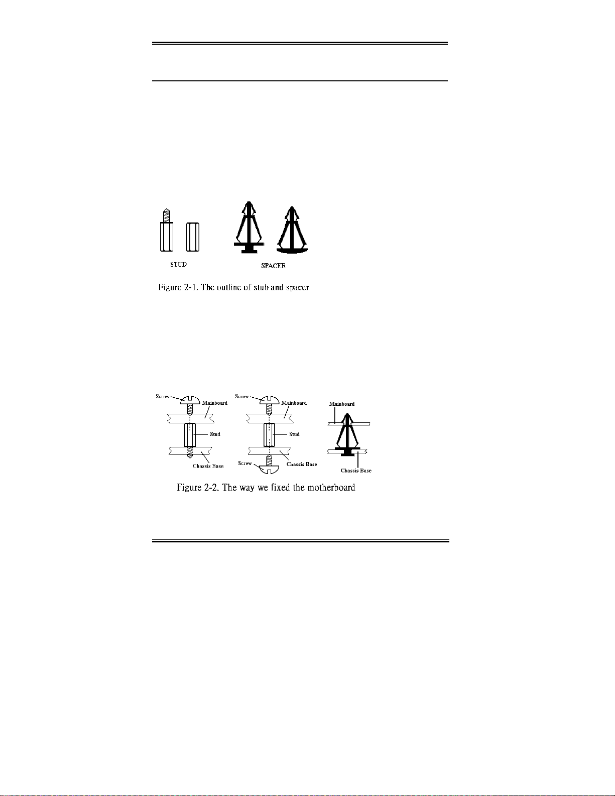
Please refer to the figure 2-1 that shows the studs and spacers, they may have several types,
but all look like t he figures below:
In principle, the best way to attach the
motherboard is with studs, and only if
you are unable to d o this should you
attach th e board with spacer s. Take a
careful look at the motherboard and
you will see many mounting holes on
it. Line these holes up with the
mounting holes on the base. If the
holes line up, an d the re are sc rew hol es
this means you can attach the motherboard with studs. If the holes line up and there are only
slots, this means you can only attach the motherboard with spacers. Take the tip of the
spacers and insert them into the slots. After doing this to all the slots, you can slide the
motherboard into po sitio n alig ned w ith the slo ts. A fter the mother boar d has be en posit ioned,
check to make sure everything is OK before putting the casing back on.
Figure 2-2 shows you the way to affix the motherboard using studs or spacers:
BE6-II
Page 13

Installing the Motherboard 2-3
Note
If the motherboard has mounting holes, but they don’t line up with the holes on the base
and there are no slots to attach the spacers, don’t worry, you can still attach the spacers
to the mounting holes. Just cut the bottom portion of spacers (the spacer may be a little
hard to cut off, so be careful of your hands). In this way you can still attach the
motherboard to th e base without worrying about s hort circuits. Sometimes you may
need to use th e pl as ti c sp rin g s to i s olat e th e s cr ew fr om t h e mo th er b oa rd P CB su rf a ce,
because the cir c uit wire may be near by the hole. Be careful, do n’ t let the screw contact
any printed ci rcuit wire or p arts on the PCB th at are n ear the fi xing h ole, otherwis e it
may damage the board or cause board malfunctioning.
2-2. Installation of the Pentium
II/III, CeleronTM CPU
The installa ti on meth od for the C PU is p rint ed on th e pack age of th e reten ti on mec hani sm
that comes with the motherboard. You can refer to it while you install the CPU. This
motherboard also supports the Celeron
TM
Celeron
Celeron
PPGA processor, you have to use a n addi tion al adapt er tha t allows you to use a
TM
PPGA processor in a slot 1 board. For this ABIT makes the SlotKET adapter.
TM
PPGA processor. If you want to install the
Note:
Installing a heat sink and cooling fan is necessary for proper heat dissipation from
!
your CPU. Failin g to install th ese items may resu lt in overheat ing and damage of
your CPU.
Please refer to your b oxed
!
processor installa tion or other document ation attached
with your CPU for detailed installing instructions.
2-3. Installing System Memory
This motherboard provides three 168-pin DIMM sites for memory expansion. The DIMM
sockets support 1Mx64 (8MB), 2Mx64 (16MB), 4Mx64 (32MB), 8Mx64 (64MB), 16Mx64
(128MB), and 32Mx64 (256 MB) or doub le si d ed DIMM m odules . Mi ni mum memory si ze
is 8MB and maxi mum mem ory size is 768 MB SDRAM . There a re th ree Memor y modu le
sockets on the system board. (Total six banks)
User’s Manual
Page 14
2-4 Chapter2
In order to create a memory array, certain rules must be followed. The following set of rules
allows for optimum configurations.
The memory array is 64 or 72 bits wide. (depending on with or without parity)
!
Those modules can be populated in any order.
!
Supports single and double density DIMMS.
!
Table 2-1. Valid Memory Configurations
Bank Memory Module Total Memory
Bank 0, 1
(DIMM1)
Bank 2, 3
(DIMM2)
Bank 4, 5
(DIMM3)
8MB, 16MB, 32MB,
64MB, 128MB, 256MB
8MB, 16MB, 32MB,
64MB, 128MB, 256MB
8MB, 16MB, 32MB,
64MB, 128MB, 256MB
8MB ~ 256MB
8MB ~ 256MB
8MB ~ 256MB
Total System Memory
8MB ~ 768MB
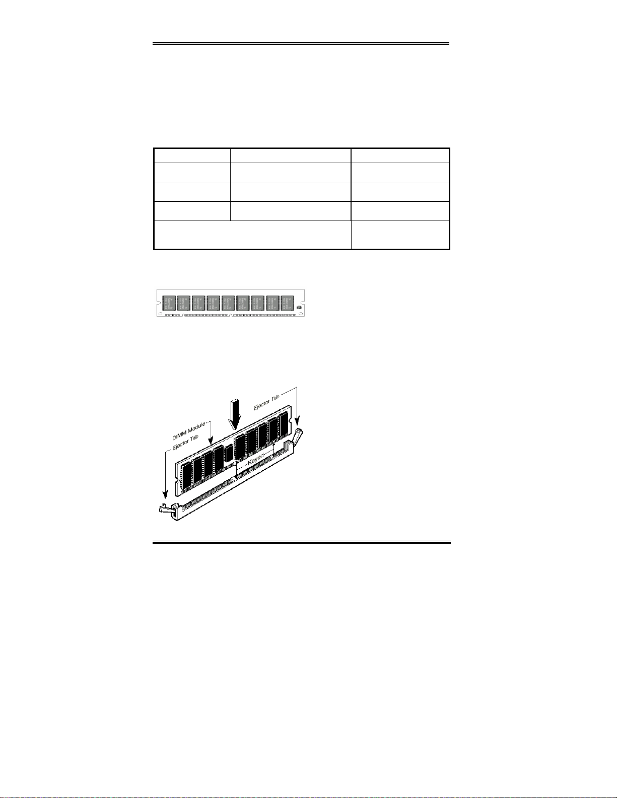
Generally, installing SDRAM modules to your motherboard is an easy thing to do. You can
refer to figure 2-3 to see what a 168-pin PC100 SDRAM module looks like.
Unlike installi ng SIMMs, DIMMs may
be "snapped" directly into the socket.
Figure 2-3 PC100 Module and Component Mark
Note: Certain DIMM sockets have minor
physical differences. If your module
doesn't seem to fit, please do not force it into the socket as you may damaged your memory
module or DIMM so cket.
The follow ing pr ocedur e w ill show y o u how to instal l a DI MM mod ule into a D I MM socke t.
Before you insta ll the memory
Step 1.
module, ple ase pl ace the com pute r pow er
switch in the
position and disconnect
off
the AC power cord from your computer.
Remove the computer’s chassis
Step 2.
cover.
Before touching any electronic
Step 3.
components, make sure you first touch
an unpainted, groun ded metal object to
discharge an y static elec trici ty stored on
your clothing or body.
Figure 2-4. Memory module installation
BE6-II
Page 15

Installing the Motherboard 2-5
Locate your computer’s 168-pin memory expansion DIMM socket.
Step 4.
Insert the DIMM modu le into the expansion so cket as shown in the i llustration.
Step 5.
Note how the module is keyed to the socket. You can refer to figure 2-4 for the
details.
This insures the D I MM modu le will be plu gged in to the soc ket in one w ay
. Firmly press th e DIMM modu le into the DIMM sock et, makin g certain t he
only
module is completely seated in the DIMM socket.
Once the DIMM modu le has been insta lled, the installa tion is complete an d the
Step 6.
computer’s cover can be replaced. Or you can continue to install other devices and
add-on cards that are mentioned in the following section.
Note
When you install a DIMM modu le fu lly i nt o the DIMM soc k et, th e ejec t tab shou ld b e
locked into the DIMM module very firmly and fit into it s indention on the bo th sides.
User’s Manual
Page 16
2-6 Chapter2
2-4. Connectors, Headers and Switches
Inside the case of any computer several cables and plugs have to be connected. These cables
and plugs are usually connected one-by-one to connectors located on the motherboard. You
need to carefully pay attention to any connection orientation the cables may have and, if any,
notice the p os iti on of th e f ir st p in of t h e con nect or. In th e exp lana ti on s that follo w, we will
describe the significance of the first pin.
We will show you all connectors, headers and switches here, and tell you how to connect
them. Please pay attention and read the whole section for necessary information before
attempting to finish all of the hardware installat ion inside the com puter chassis.
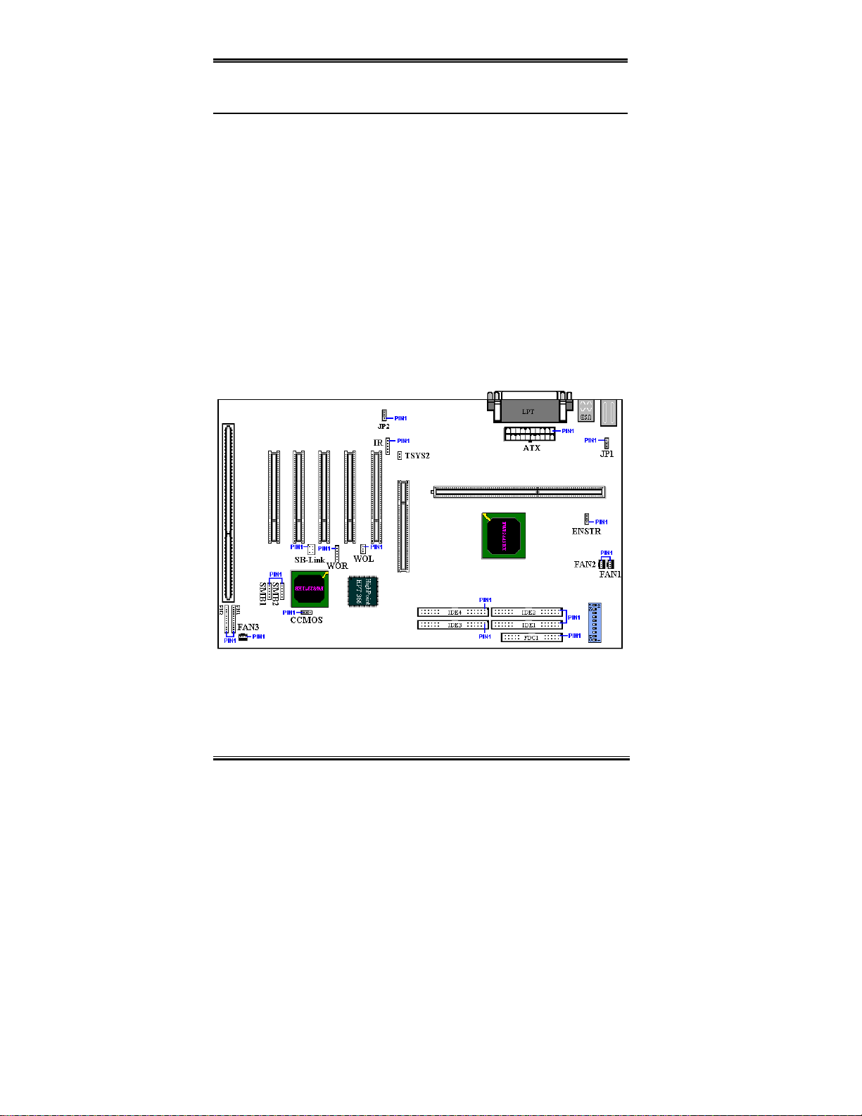
Figure 2-5 s how s y o u all of the co nnec to rs and he ade rs that w e ’l l dis cuss in t he nex t se ctio n,
you can use this diagram to visually locate each connector and header we describe.
All connectors, headers and switches mentioned here, will depend on your system
configuration. Some features you may (or may not) have and need to connect or configure
depending on the peripheral . I f y our system doe s n't hav e such add-on car ds o r s witches you
can ignore some special feature connectors.
Figure 2-5. All Connectors and Headers for the BE6-II
First, Let’s see the headers that BE6-II uses, and what their fun ctions are.
BE6-II
Page 17
Installing the Motherboard 2-7
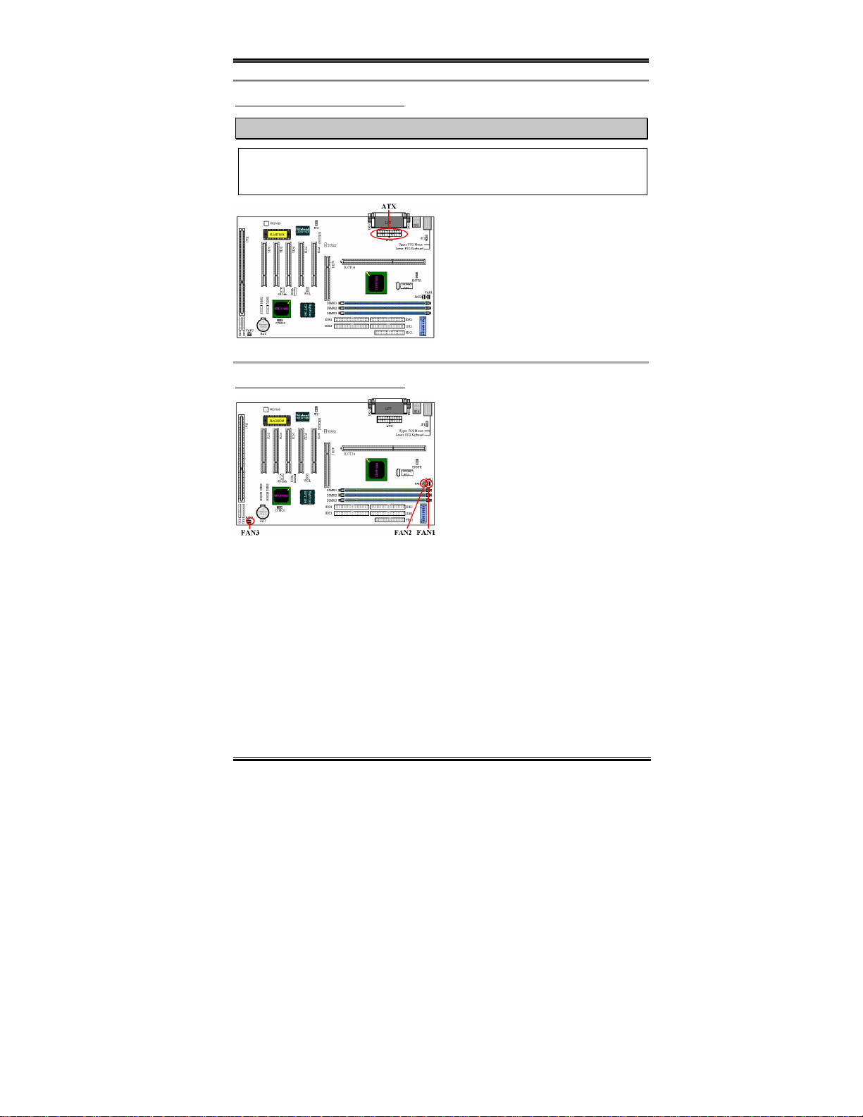
ATX: ATX Power Input Connector
Caution
If the power supply connectors are not properly attached to the ATX power supply, the
power supply or add-on cards may be damaged .
Attach the connector from the power supply
to the ATX connector here. Remember you
have to push the connector from the ATX
power supply firmly to the end with the
ATX connector, insuring that you have a
good connection.
Note: Watch the pin position and the
orientation
FAN1, FAN2 & FAN3: FAN h eader
Attach the connector from the individual
CPU fan to the header named FAN1, and
attach the con nector fr om the chas sis fan t o
FAN2 or & FAN3 header.
You must attach the CPU fan to the
processor, or your processor will work
abnormally or may be damaged by
overheating. Also, if you want the computer
case’s internal temperature to be kept steady and not too high, you had better connect the
chassis fan to reach this goal.
Note: Watch the pin position and the orientation
User’s Manual
Page 18
2-8 Chapter2
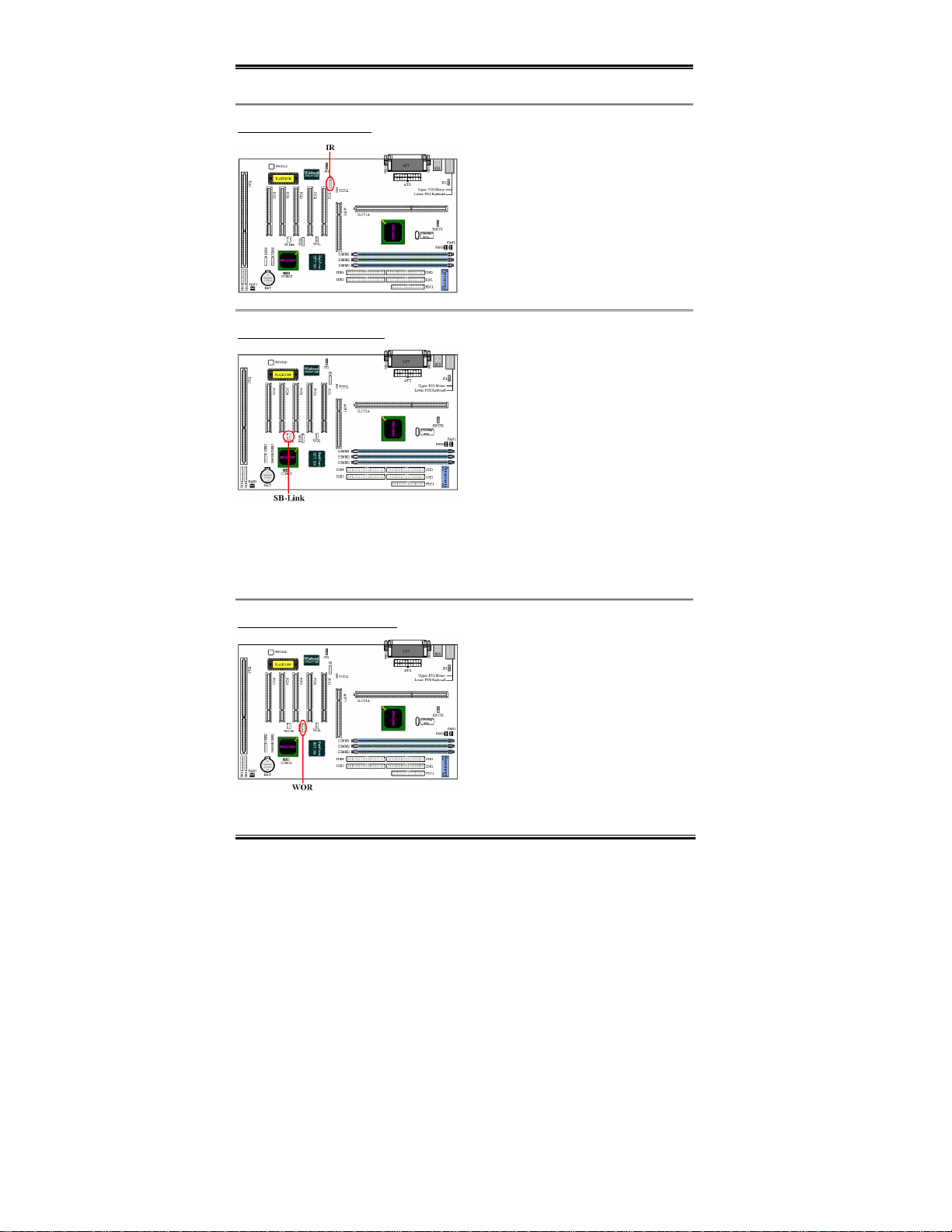
IR: IR Header (Infrared)
There is a specific orientation for pins 1
through 5, att ach the conn ector from t he IR
KIT or IR device to the IR header. This
motherboard supports standard IR transfer
rates.
Note: Watch the pin position and the
orientation
SB-Link: SB-Link
™
Header
If your PCI audio adapter supports this
feature, th en you can connect t he specific
cable from the audio adapter to this header.
SB-LINK
™
combines Intel's PC-PCI and
"Serialized IRQ" protocols. These
technolog ie s can be found in Intel's TX, LX,
BX and newer core logic chipsets. This
technology provides the DMA and IRQ
signals present in ISA Bus today, but not
available on t he PCI Bus. The SB- LINK
™
serves as a bridge between the motherboard and
PCI sound card to deliver Sound card for real-mode DOS games. Check to see if your card
supports this.
Note: Watch the pin position and the orientation
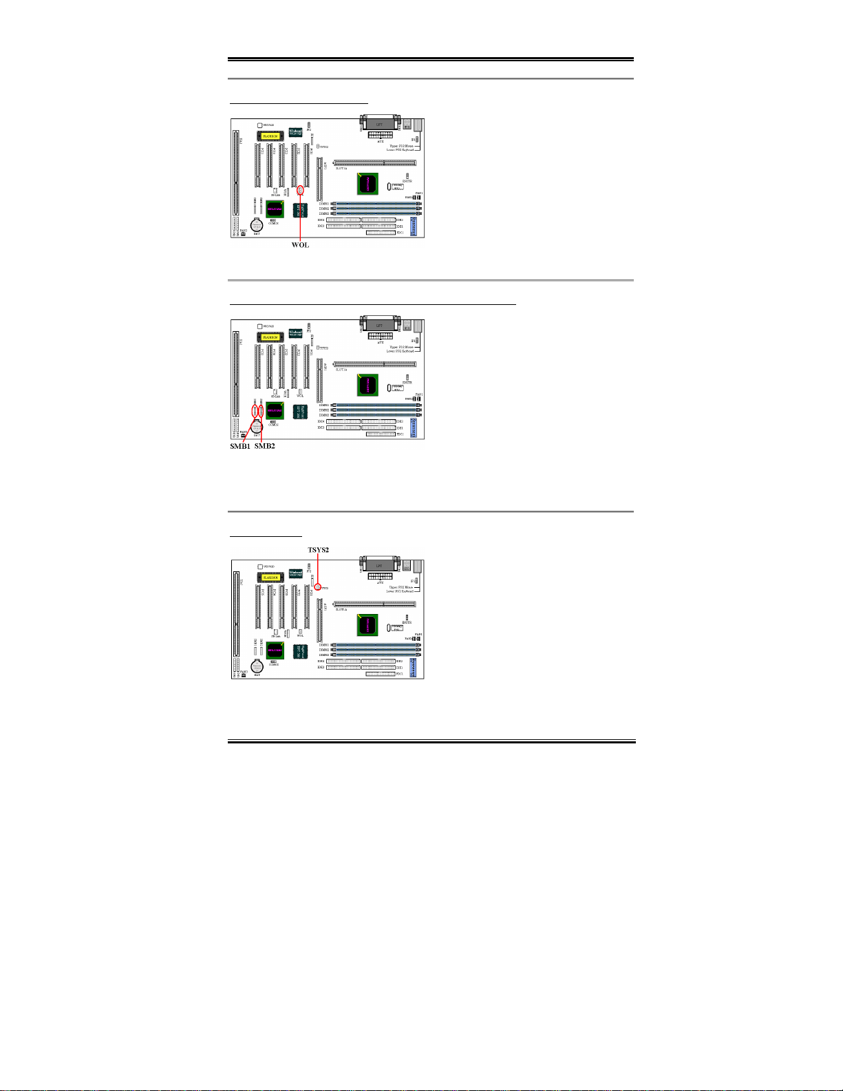
WOR: Wake On Ring Header
If you have an internal modem adapter that
supports this feature, then you c an connect
the speci fic cable f rom the inter nal mod em
adapter to th is header. This fea ture lets you
wake up your computer via remote control
through the modem.
Note: Watch the pin position and the
orientation
BE6-II
Page 19
Installing the Motherboard 2-9
WOL: Wake on LAN Header
If you have a Network adapter th at supp ort s
this feature, then you can connect the
specific ca ble from the network adapter to
this header. This feature lets you wake up
your computer via remote control th rough a
local area network. You may need a specific
utility to control the wake up event, like
using the Intel
®
LDCM® utility or other
similar utilit ies.
Note: Watch the pin position and the orientation
SMB1 & SMB2 header: System Management Bus Connector
This connector is reserved for system
management bus (SMBus). The SMBus is a
specific implementation of an I
2
C bus. I2C is
a multi-master bus, which means that
multiple chips can be connected to the same
bus and each one can act as a master by
initiating a data transfer. If more than one
master simultaneously tries to control the
bus, an arbitration procedure decides which
master gets priority.
Note: Watch the pin position and the orientation
TSYS2 header:
The TSYS2 is for you to connect an
additional thermistor to detect the
temperature in the location of your choice.
You can attach one end of the two-t hread ed
thermal cable that comes with the
motherboard to the TSYS2 header, then tape
the other end of th erm al cab le on th e d evi ce
you want to detect its temperature.
User’s Manual
Page 20
2-10 Chapter2
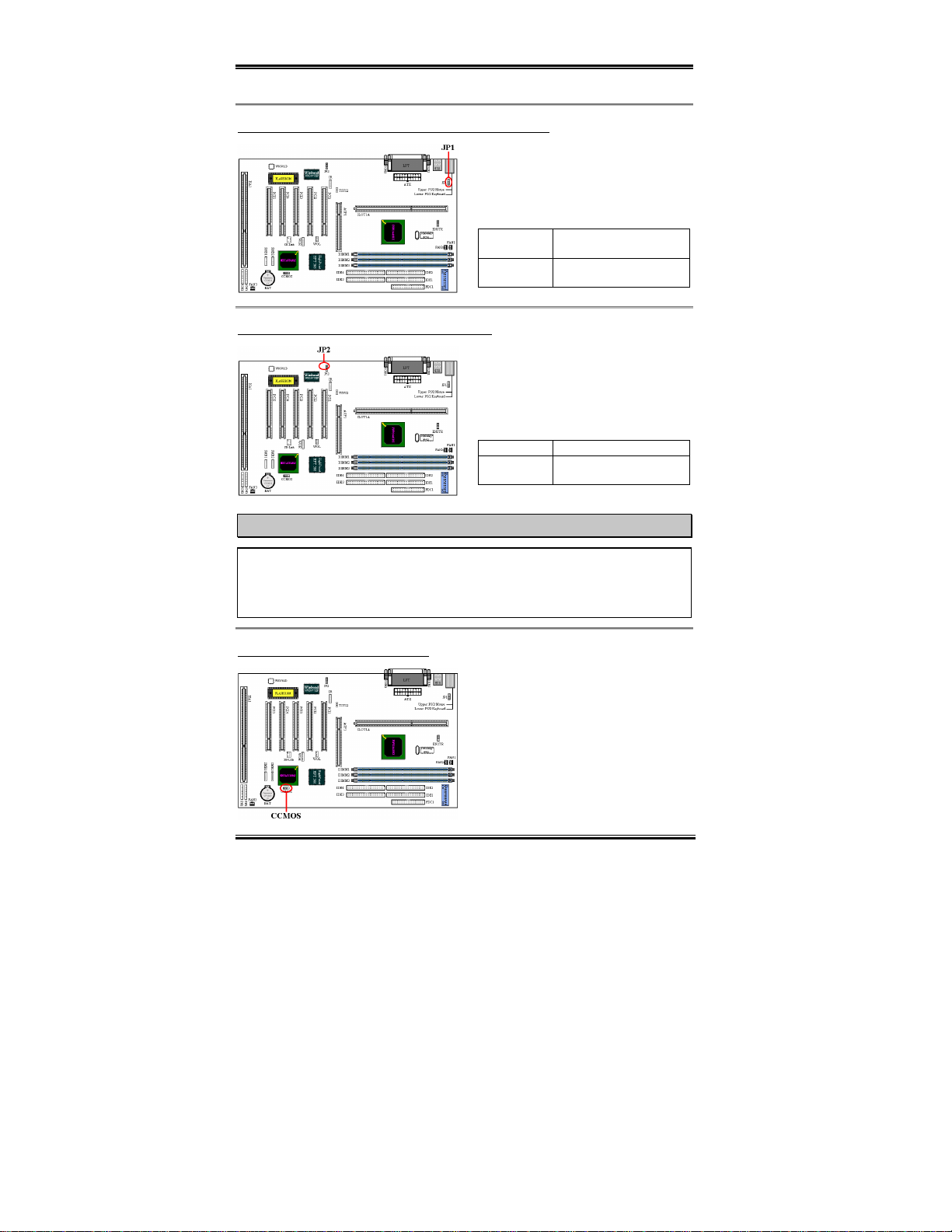
JP1 Header: Disable or Enable Keyboard/Mouse Wake Up
This header is used to Disable or Enable
keyboard/mouse wake up function. This
function has to cooperate with the BIOS
setting (see section 3-5).
Short pin 1-2 Disable keyboard/mouse
Short pin 2-3 Enable keyboard/mouse
Wake Up
Wake Up (default)
JP2 Header: Disable or Enable Power Recovery
This header is used to Disable or Enable
power recovery function. This function has
to cooperate with the BIOS setting (see
section 3-5).
Short pin 1-2 Disable power recovery
Short pin 2-3 Enable power recovery
(default)
NOTE
If you enable t he po w er re cove ry funct ion and co nne ct a Z I P dev ice to the L PT po rt, y o u
have to turn off the power of your ZIP device after you shutdown your computer.
Otherwise, the onboard battery will run down.
CCMOS: CMOS Discharge Jumper
Jumper CCM O S discharge CMOS memory.
When you install the motherboard, make
sure this jumper is set for normal operation
(pin 1 and 2 shorted). See figure 2-6.
BE6-II
Page 21
Installing the Motherboard 2-11
Normal Operation (Default) Discharge CMOS
Figure 2-6. CCMOS jumper setting
Note
Before you clear the CMOS, you have to turn th e power off first (including t he +5V
standby power). Otherwise, your system may work abnormally or malfunction.
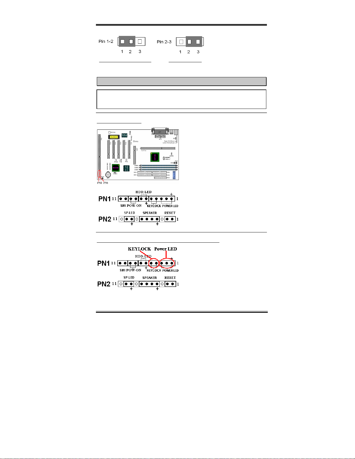
PN1 and PN2 Headers
PN1 and PN2 are for switches and indicators
for the chassis’s front panel, there are
several functi ons that come from thes e two
headers. You have to watch the pin position
and the orientation, or you may cause
system malfunction s. Figure 2 -7 shows you
the PN1 and PN2 functi ons of the pins.
Figure 2-7. The definition of PN1 and
PN2 pins
PN1 (Pin 1-2-3-4-5): Power LED and Keylock Switch Headers
There is a specific orientation for pins 1
through 3. Insert the three-threaded power
LED cable to pins 1~3, and t he tw o- threade d
keylock cable i nto pin 4 and pin 5. Check to
make sure the correct pins go to the correct
connectors on the motherboard. If you
install them with the wrong direction, the
power LED light will not illuminate correctly.
Note: Watch the power LED pin position and ori entation.
User’s Manual
Page 22
2-12 Chapter2
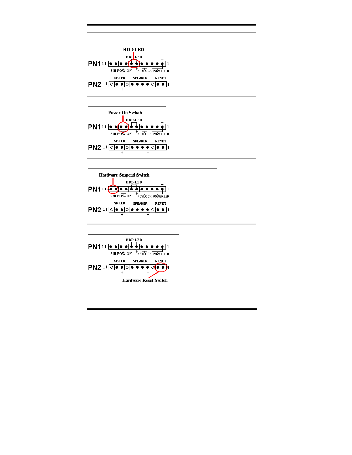
PN1 (Pin 6-7): HDD LED Header
Attach the cable f rom th e cas e’s fron t pan el
HDD LED to this header. If you install it in
the wrong direction , the LED light will not
illuminate correctly.
Note: W at c h t he HDD LED pi n position and
the orientation.
PN1 (Pin 8-9): Power on Switch Header
Attach the cable f rom th e cas e’s fron t pan el
power switch to this header.
PN1 (Pin 10-11): Hardware Suspend Switch (SMI Switch) Header
Attach the cable f rom th e cas e’s fron t pan el
suspend switch (if there is one) to this
header. Use this switch to enable/disable the
power management function by hardware.
Note: If you enable the ACPI function in the
BIOS setup, this function will not work.
PN2 (Pin 1-2): Hardware Reset Switch Header
Attach the cable f rom th e cas e’s fron t pan el
Reset switch to this header. Press and hold
the reset button for at least one second to
reset the system.
BE6-II
Page 23
Installing the Motherboard 2-13
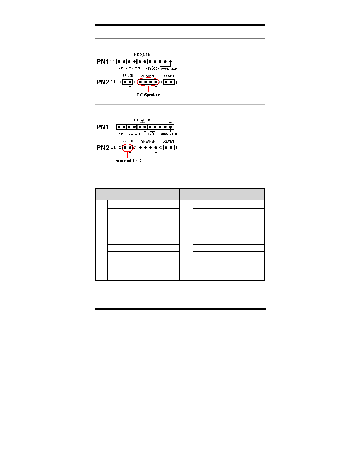
PN2 (Pin 4-5-6-7): Speaker Header
Attach the c ab le fro m t h e syst em sp ea k er t o
this header.
PN2 (Pin 9-10): Suspend LED Header
Insert the two-t hreaded suspend LED c able
into pin 9 and pin 10. If you insta ll it in the
wrong direction, the LED light will not
illuminate c orrectly.
Watch the HDD LED pin position
Note:
and the orientat io n.
For the PN1 and PN2 pin’s count-name list, please refer to table 2-2.
Table 2-2. PN1 and PN2 pin count name list
PIN Name Significance of signal PIN Name Significance of signal
PIN 1 +5VDC PIN 1 Ground
PIN 2 No connection PIN 2 Res et input
PIN 3 Ground PIN 3 No connection
PIN 4 Keyboard inhibit Signa l PIN 4 +5VDC
PIN 5 Ground PIN 5 Ground
PN1
PIN6 LED power PIN6 Ground
PIN 7 HDD active PIN 7 Speaker data
PIN 8 Ground PIN 8 No connection
PIN 9 Power On/Off signal PIN 9 +5VDC
PIN 10 +3V Standby PIN 10 Suspend LED active
PIN 11 Suspend signal
Let’s now see the I/O connectors that BE6-II uses, and what their functions are.
PN2
PIN 11 No connection
User’s Manual
Page 24
2-14 Chapter2
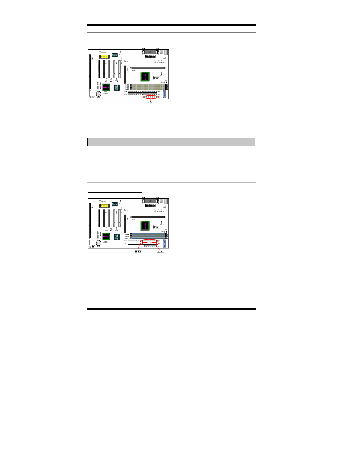
FDC1 Connector
This 34-pin connector is c alled the “
disk drive connector
360K, 5.25”, 1.2M, 5.25”, 720K, 3.5’’,
1.44M, 3.5” or 2.88M, 3.5” floppy disk
drive, you can even connect a 3 Mode
floppy disk drive (it’s a 3 1/2” drive used in
Japanese computer systems).
A floppy disk drive ribbon cable has 34
wires and two conn ectors to provide for th e connection of two flopp y disk drives. After
connecting th e single en d t o the FDC 1, c onnect th e two co nn ectors on the ot her end to th e
floppy disk drives. In general, people only install one floppy disk drive on their computer
system.
Note
A red mark on a wire typically designates the location of pin 1. You need to align the
wire pin 1 to the FDC1 connec tor pin 1, then inser t the wire c onnect or int o the FDC1
connector.
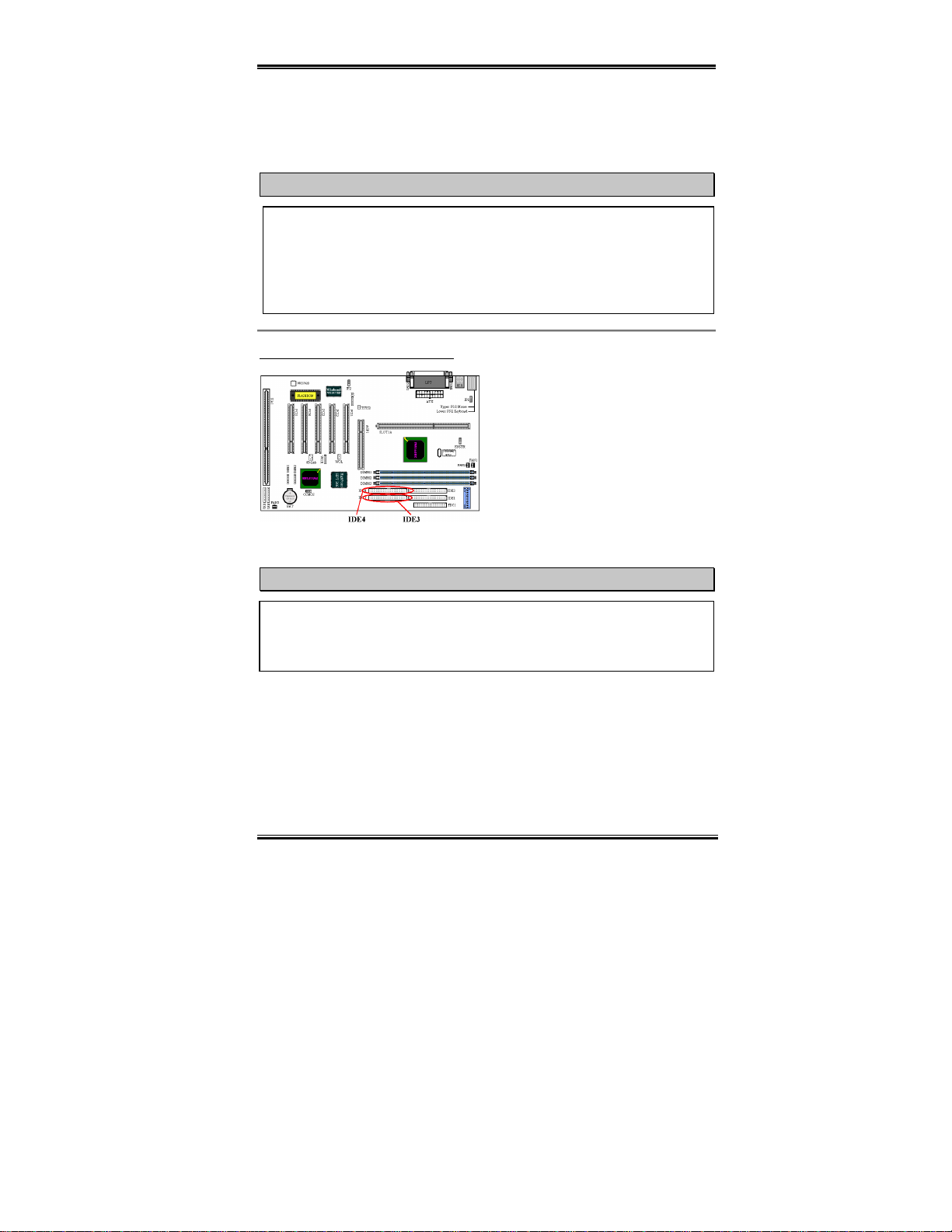
IDE1 and IDE2 Connectors
An IDE hard disk drive ribbon cable has 40
wires and two connectors to provide a
connection for two IDE hard disk drives.
After connecting the single end to the IDE1
(or IDE2), connect the two connectors on
the other end to the IDE hard disk drives (or
CD-ROM drive, LS-120, etc.).
”. You can connect a
floppy
Before you install a hard disk, there are
some things you need to be aware of:
“Primary” refers to the first connector on the motherboard, that is, the IDE1 connector on
♦
the motherbo ard.
“Secondary” refers to the second connector on the motherboard, that is, the IDE2
♦
connector on t he motherboard.
Two hard disks can be connected to each connector:
♦
The first HDD is referred to as the “Master”,
BE6-II
Page 25
Installing the Motherboard 2-15
The second H D D is referred to as the “Slave” .
For performance issues, we strongly suggest you don’t install a CD-ROM drive on the
♦
same IDE channel as a har d disk. O therw ise, the sys tem perf orma nce on th is channe l may
drop. (how much depends on your CD-ROM drive performance)
Note
The Master or S la ve st a t u s of th e h a rd di sk d ri ve i s s et on th e h a rd di sk it s elf. Plea s e
!
refer to the hard disk drive user’s manual.
A red mark on a wire typically designates the location of pin 1. You need to align the
!
wire pin 1 to the IDE1 (or IDE2) connector pin 1, then insert the wire connector into
the IDE1(or IDE 2) connector.
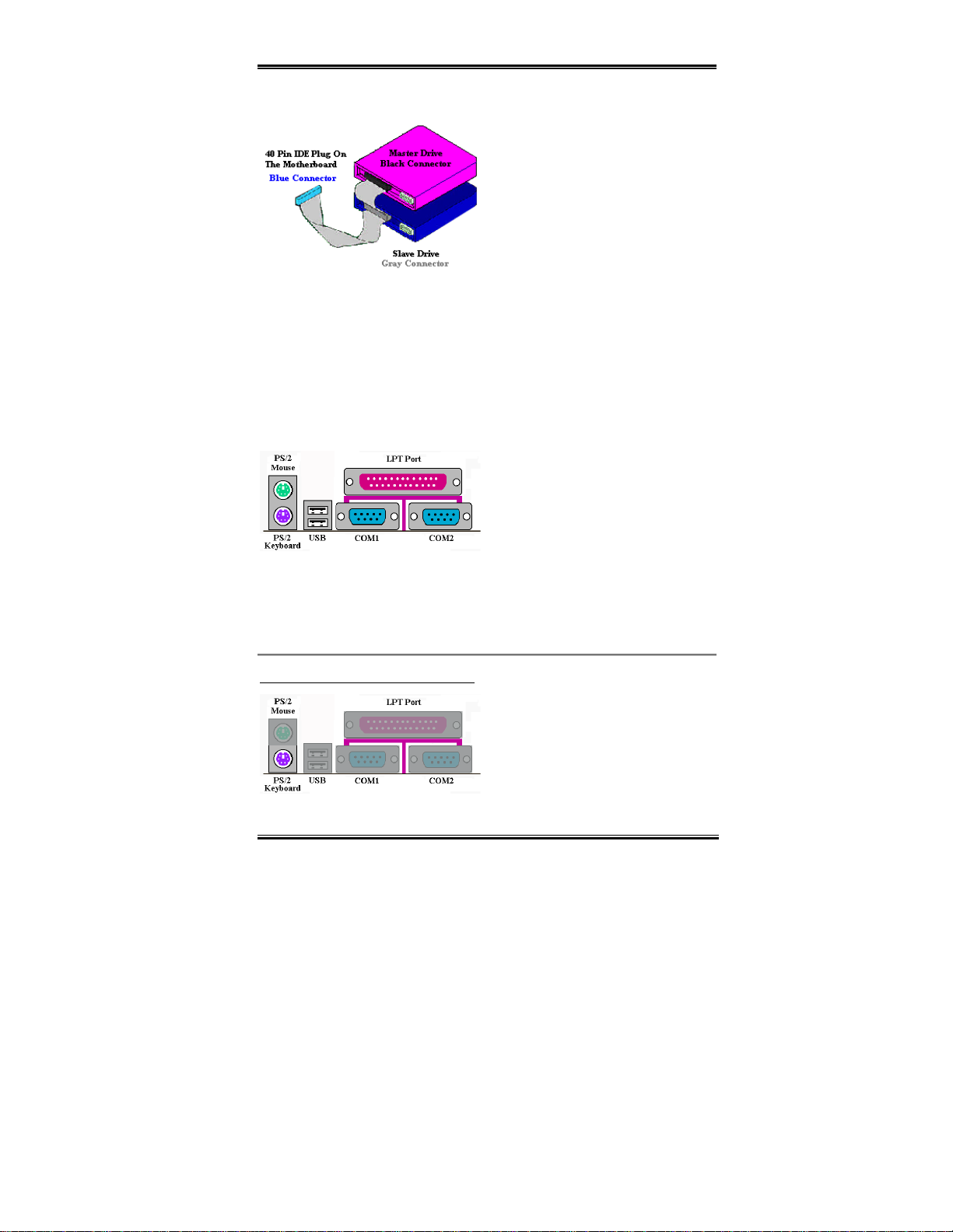
IDE3 and IDE4: ATA/66 Connec tors
The BE6-II s uppor ts the Ul tra AT A /66 (A l so
known as Ultra DMA/66) specification. It
enhances existing Ultra ATA/33 technology
by increasing both performance and data
integrity. This new high-speed interface
doubles the U l tr a ATA/33 burst data transfer
rate to 66.6 Mbytes/sec. The result is
maximum disc performance using the
current PCI loca l bus environment. Figu re
2-8 shows you the different between the Ultra ATA/33 and Ultra ATA/66 Conductor Cable.
NOTE
HPT 366 IDE controller is designed to support high-speed mass storage. Thus we don’t
suggest yo u conne ct no n- dis k de vice s t hat use AT A /ATA PI inter face s, s uch a s CD-RO M
to HPT 366 IDE connector (IDE3&IDE4).
User’s Manual
Page 26

2-16 Chapter2
Figure 2-8. The difference between Ultra ATA/33 and Ultra ATA/66 Conductor Cables
Figure 2-9 shows you a photo of an Ultra ATA/66 Conductor Cable. An Ultra ATA/66 capable cable i s a 40-pin, 80-conductor cab le with a black connec tor on one end, a blue
connector on th e other en d and a gra y connect or in th e middle. In addit ion, lin e 34 on th e
cable should be notched or cut (this may be difficult to see).
Ultra ATA/66 is backwards compatible with all Ultra ATA/33 systems, but it will be limited
in its transfe r mo de to the Ul tra AT A /33 ( Ul tra D MA Mo de 2 - 33 Mby t es /se c) o r PIO Mode
4 (16.6 Mbytes/sec). Ultra ATA/66 hard drives are 100 percent backward compatible with
both Ultra ATA/33 and DMA and with existing ATA (IDE) hard drives, CD-ROM drives,
and host systems . The Ultra ATA/66 pro to col and commands ar e designed to be co mp atible
with existi ng AT A (I DE) device s and sy stem s. A ltho ugh a new 40-pin , 80- cond uctor cabl e is
required for Ultra ATA/66, the chip set pin connector remains the same at 40. Hard drives
that support Ultra ATA/66 also support Ultra ATA/33 and legacy ATA (IDE) specifications.
Figure 2-9. P hot o of an Ult ra
ATA/66 Conductor Cable
BE6-II
There are four requirements for attaining Ultra ATA/66:
*The drive must support Ultra ATA/66.
*The motherboard and system BIOS (or an add-in
controller) must s upport Ultra ATA/66.
*The operating system must support Direct Memory
Access (DMA); Microsoft Windows 98 and Windows
95B (OSR2) support DMA.
*The cable must be 80-conductor; the length should not
exceed 18 inch es. If all the a bove requ irements are met,
you can enjoy the Ultra ATA/66 features of your
computer system.
Page 27
Installing the Motherboard 2-17
How to install the Ultra ATA/66 Cable Assembly:
The
&
into the mothe r boar d or y our s y ste m will not
work.
&
cable assemb ly has a small pola rization tab
centrally located on the body of the plastic.
This fits into the matching slot on the mating
plugs on the motherboard and the drives,
Figure 2-10. How to connect an ATA/66
Cable to the Motherboard
The red line on t he cabl e sho ul d be al igned w it h pi n #1. O n the driv es th is wi ll r esul t in t he
&
red line facing the power connector. Attach the BLUE connector to the appropriate 40 pin
IDE plug on the motherboard.
Attach the BLACK connector to the mating plug on the master hard drive. Attach the
&
GREY connect or to the mating plug on the sla ve drive (secondary hard drive, CD ROM,
or tape drive). Please refer figure 2-10.
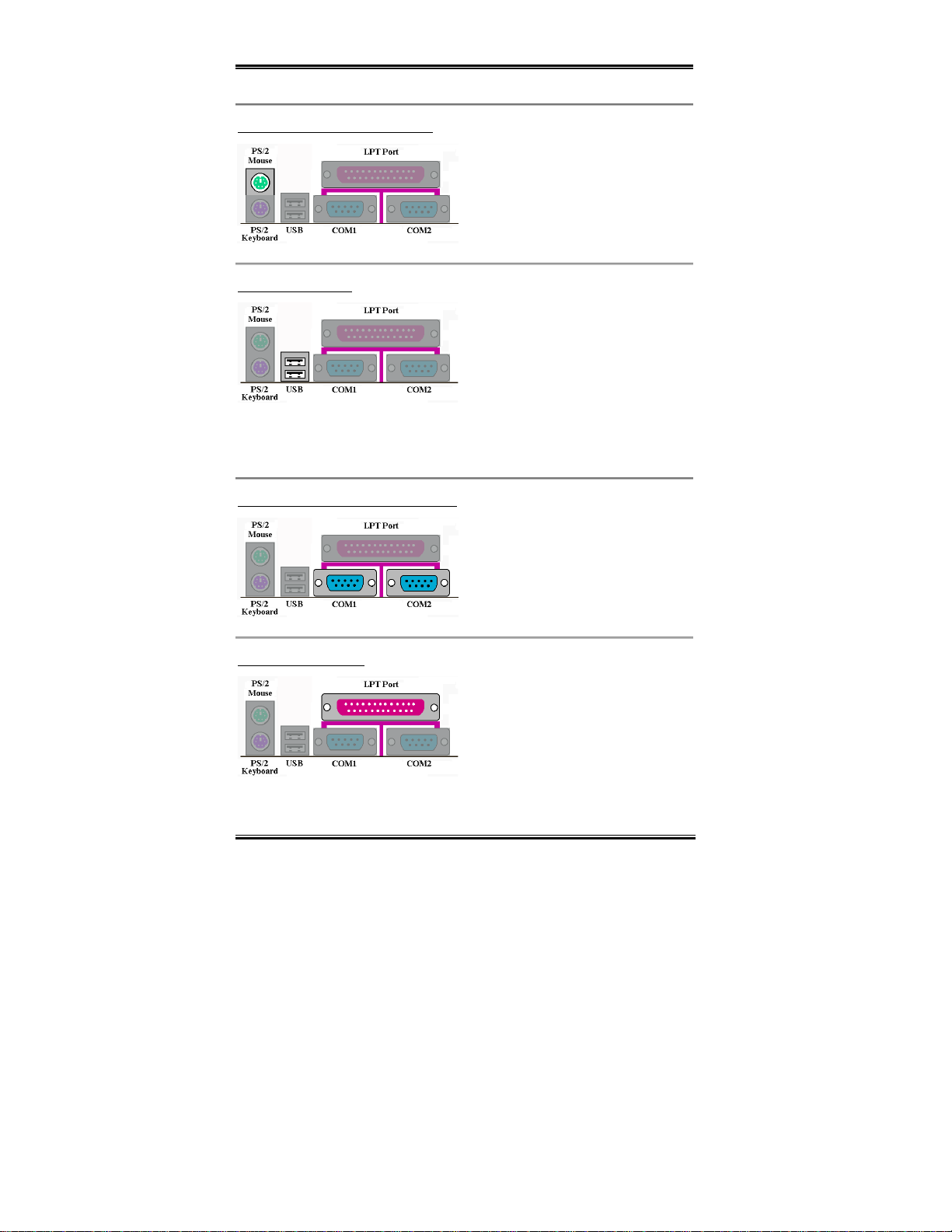
Figure 2-11. BE6-II back panel connectors
Figure 2-11 shows the BE6-II back panel connectors, these connectors are for connection to
outside devices to the motherboard. We will describe which devices will attach to these
connectors below.
thus assuring p ositi ve ma ting (pi n #1 to pi n
#1)
connector
BLUE
Each connect or on the Ultra ATA/66
MUST
be plugged
KBM Lower: PS/2 Keyboard Connector
Attach a PS/2 keyboard connector to this 6pin Din-connector. If you use an AT
keyboard, you can go to a computer s tore t o
purchase an AT to ATX converter adapter,
then you can connect your AT keyboard to
this connector. We suggest you use a PS/2
keyboard for best compatibility.
User’s Manual
Page 28
2-18 Chapter2
KBM Upper: PS/2 Mouse Connector
Attach a PS/2 mouse to this 6-pin Din-
connector.
USB Port Connectors
This motherboard provides two USB ports.
Attach the USB connector from the
individual d evice to these connect ors. You
can attach U SB devices such as a, scanner,
monitor, mouse, keyboard, hub, CD-ROM,
joystick et c. to one of each USB connec tor.
Y ou must make sure your operating system supports this feature and you may need to install
an additional driver for individual devices. Please refer to your device user’s manual for
detailed infor mation.
Serial Port COM1 and COM2 Connector
Parallel Port Connector
BE6-II
This motherboard provides two COM ports,
you can connect an external modem, mouse
or other devices that support this
communication protocol.
This parallel port is also called an “LPT”
port, because it usually connects to the
printer. You can connect oth er devices that
support this c ommunic ation p rotoc ol, like a
scanner, M.O. drive, etc.
Page 29

Installing the Motherboard 2-19
2-5. CPU Frequency Settings
The BE6-II provides two ways to configure CPU settings. One uses the ABIT CPU Soft
Menu III techn ology, the other us es DIP Switches. You can use the DS10 to enable or
disable Soft Menu III.
NOTE
When you enable Soft Menu III, all DIP switches must be set to OFF.
DIP SW (DS1~DS8): DIP Switch for Setting CPU Frequency
The follow ing tabl es w ill prese nt the a djust ment f or the CPU fr equency and m ult iplie r fac tor.
(The default settings are all “OFF.”)
Multiplier
Factor
1.5 ON OFF ON ON 66 OFF OFF OFF OFF
2.0 OFF ON ON OFF 75 OFF ON OFF OFF
2.0 ON OFF OFF ON 83 ON OFF OFF OFF
2.5 OFF OFF ON OFF 100 OFF OFF ON OFF
3.0 OFF ON OFF OFF 103 ON ON ON OFF
3.5 OFF OFF OFF OFF 112 OFF ON ON OFF
4.0 OFF ON ON ON 124 ON ON OFF OFF
4.5 OFF OFF ON ON 133 ON OFF ON OFF
5.0 OFF ON OFF ON
5.5 OFF OFF OFF ON
6.0 ON ON ON OFF
6.5 ON OFF ON OFF
7.0 ON ON OFF OFF
7.5 ON OFF OFF OFF
8.0 ONONONON
AGP Frequency
The DS9 lets you set the frequency ratio between AGP clock and the Front Side Bus (CPU
Bus). Generally, if you set the CPU FSB clock to 66MHz, you ought to set this switch to
“OFF (1/1)”. If you set the CPU FSB clock to 100Mhz or higher, you ought to set this switch
to “ON (2/3)”
DS1DS2DS3DS4
External
Clock
Frequency
DS5DS6DS7DS8
User’s Manual
Page 30

2-20 Chapter2
DS9
ON AGP Clock / Front Side Bu s = 2/3
OFF AGP Clock / Front Sid e Bus = 1/1
Soft Menu III
The DS10 lets you enable or disable Soft Menu III. The Soft Menu III allows you to
configure the CPU settings easily through BIOS setup (refer to section 3-1). When you
enable Soft Menu III, all DIP switches must be set to OFF.
DS10
ON Disable Soft Menu III
OFF Enable Soft Menu III
BE6-II
Page 31

Introduction of th e BIO S 3-1
Chapter 3. Introduction of the BIOS
The BIOS is a program located on a Flash Memory chip on the motherboard. This program
will not be lost when you turn the computer off. This program is also referred to as the
“boot” program. It is the only channel for the hardware circuit to communicate with the
operating system. Its main function is to manage the setup of the motherboard and interface
cards parameter s, incl ud ing s impl e par ame ter s such as t ime, date , har d disk d rive , as w e ll as
more complex paramet ers su ch a s hard ware synch ron i zati on, devi c e opera ti n g mode,
SOFT MENU™ III
or will ope r ate at its best, onl y if all the se parameters ar e co r r e ctly and optimal ly configured
through the BIOS.
Do not change the parameters inside the BIOS unless you fully understand
''''
their meanings and consequences.
The parameters inside the BIOS are used to setup the hardware synchronization or a
device’s operating mode. If the parameters are not correct, they will produce errors, the
computer will crash, and so metime s yo u will even not be able to boot the compu ter af ter
it has crashed. We recommend that you do not change the parameters inside the BIOS
unless you are very familiar with them. If you are not able to boot your computer
anymore, please refer to t he “CMOS Discharge Jumper” in Section 2-4, Cha pter 2.
features and setu p of CP U sp eed . Th e comp ut er wi ll op er at e n or ma ll y,
CPU
When you start the computer, it is controlled by the BIOS program. The BIOS first operates
an auto-diagnostic test called POST (Power On Self Test) for all the necessary hardware, it
then configures the parameters of the hardware synchronization, and detects all the
hardware. Only when thes e tasks a re complet ed does i t give up cont rol of the c omputer t o
the program of the next level, which is the operating system (OS). Since the BIOS is the only
channel for hardware and software to communicate, it is the key factor for system stability,
and in insuring that your system performs at its best. After the BIOS has achieved the
auto-diagnostic and auto-detection operations, it will display the following message :
PRESS DEL TO ENTER SETUP
The message will be displayed for three to five seconds, if you press the
access the BIOS Setup menu. At that moment, the BIOS will display the following screen:
key, you will
Del
User’s Manual
Page 32

3-2 Chapter3
Note
To improve stabil i ty and functions , BIOSes ar e constantly impr o v ing , therefore; the
(
BIOS screens i n this chapter m ay not fully match your current BIOS screen.
All default setting is use the
)
Fail-Safe Defaults
, some items defa ult values will be changed.
Load Optimized Defaults
settings. If you use the
Load
Figure 3-1. CMOS Setup Utility Main Screen Shot
This motherboard uses a totally different operating interface so the Award BIOS screens are
different than in other versions. It provides more functions with increased user friendliness.
In the BIOS Setup main men u in Figure 3- 1, you can see severa l option s. We will explain
these option s st ep b y step in th e f ollowing p ages of t hi s chap ter, but let u s firs t see a short
description of the function keys you may use here:
!
Press
(up, down, and right) to choose the option you want to confirm or to modify
!!!!""""####$$$$
in the main m enu .
Press the
!
key to select the item you wan t. Si mply move th e highli ght to the field
Enter
you want to select, and press Enter.
!
Press
when you have completed setting up the BIOS parameters to save them and exit
F10
the BIOS Setup menu.
Press
!
Press F1 to display the Genera l Help screen.
!
In addition to the
Esc
to
Exit
the BIOS Setup.
Item Help
window, more information can be provided for the alternate
BE6-II
Page 33

Introduction of th e BIO S 3-3
function by pressing the F1 key in any menu in the BIOS.
Press F5 to reset current screen settings to their Setup Default values.
!
Press F6 to return to the
!
causing a syste m bo ot f a ilur e, use this f unct ion ke y to qu ickl y r etur n to t he s y ste m de faul t
settings.
Press F7 to quickly set the system to the
!
Fail-Safe Default
setting i.e. if you use t he wrong settings
Optimized Defaults
In some setup menu screens, you can see the
scroll bar on the ri ght side of the window.
You can use the * and + keys or the up and
down arrow keys to scroll the screen to view
more help information or functions to select.
You may see the right cursor symb ol app ea r
on the left side of some items, indicating that
additional information or options can be
select in a Sub-Menu for this item.
setting.
Note
The item heading in the square outlet represents the default setting for that field
Computer Knowledge: CMOS Data
Maybe you have heard of someone losing CMOS DATA. What is the CMOS? Is it
important? CMOS is the memory in which the BIOS parameters that you have
configured are stored. This memory is passive, you can both read its data, and store data
in it. But this memory has to be powered by a battery in order to avoid data loss when
the computer is turned off. If the CMOS battery dies, you will loose all CMOS data. We
therefore recommend that you write down all the parameters of your hardware, or you
put a label with these parameters on your hard disk.
User’s Manual
Page 34

3-4 Chapter3
3-1. SoftMenu III Setup
™
The CPU can be setup through a programmable switch (
CPU SOFT MENU
replaces the traditional manual hardware configuration. This feature allows the user to more
easily complete the installation procedures. You can install the CPU without configuring any
jumpers or switches. The CPU must be setup according its specifications.
III
), that
Figure 3-2. CPU Soft Menu
TM
III Screen Shot
System Processor Type:
➤ Intel Pentium III
➤ Intel Pentium II
➤ Intel Celeron
MMX
MMX
MMX
CPU Operating Frequency:
This option sets the CPU speed.
In this field, the CPU speed is indicated like this: CPU speed = External clock * Multiplier
factor, select the CPU speed according the type and the speed of your CPU.
For Intel Pentium II and Celeron™ PPGA MMX processors, you can choose the following
settings:
BE6-II
Page 35

Introduction of the BIOS 3-5
➤233 (66) ➤266 (66) ➤300 (66) ➤333 (66) ➤300 (100)
➤350 (100) ➤400(100) ➤450 (100) ➤366 (66) ➤400 (66)
➤433 (66) ➤466 (66) ➤500 (66) ➤533 (66) ➤533 (133)
➤500 (100) ➤550 (100) ➤600(100) ➤600 (133) ➤650 (100)
➤667 (133) ➤700 (100) ➤750 (100) ➤800 (100) ➤733 (133)
➤800 (133) ➤User Define
Note
CPU bus speed above 66MHz/100MHz supported but not guaranteed due to the PCI
and chipset specs.
User defined external clock and multiplier factor:
➤➤➤➤
User Defined:
When you choose the User Define, you will be able to set the following five items.
!!!!
!!!!
!!!!!!!!
The wrong settings of the multiplier and external clock in certain circumstances may
cause CPU damage. Setting the working frequency higher than the PCI chipset or
processor specs, may cause abnormal memory module functioning, system hangs,
hard disk drive data lose, abnormal functioning of the VGA card, or abnormal
functioning with other add-on cards. Using non-specification settings for your CPU is
not the intention of this explanation. These should be used for engineering testing, not
for normal applications.
War ni ng
!!!!
!!!!
!!!!!!!!
If you use non-specification settings for normal operation, your system may not be
stable, and may effect system reliability. Also, we do not guarantee the stability and
compatibility for settings that are not within specification, and any damage of any
elements on the motherboard or peripherals, is not our responsibility.
✏✏✏✏
CPU FSB Clock:
➤66MHz (1/2) ➤75MHz (1/2) * ➤83MHz (1/2)*
➤84Mhz ~ 200MHz
Note
CPU bus speed above 66MHz/100MHz supported but not guaranteed due to the PCI
and chipset specs.
User’s Manual
Page 36

3-6 Chapter3
✏✏✏✏
Multiplier Factor:
You can choose the following multiplier factors:
➤ x 2 ➤ x 2.5 ➤ x 3 ➤ x 3.5 ➤ x 4 ➤ x 4.5 ➤ x 5 ➤ x 5.5 ➤ x 6
➤ x 6.5 ➤ x 7 ➤ x 7.5 ➤ x 8
✏✏✏✏
SEL100/66# Signal
Two options are available: Default and Low. The default setting is “Default”.
✏✏✏✏
PCI Clock/CPU FSB Clock
Three options are available: 1/2, 1/3 and 1/4. This item lets you set the PCI bus clock.
It correlates with the CPU FSB clock you set. For example, if you set the CPU FSB
clock to 100MHz and choose 1/3 here, the PCI bus clock will be 33.3 MHz.
✏✏✏✏
AGP Clock/CPU FSB Clock
Two options are available: 1/1 and 2/3. This item lets you set the AGP clock. It
correlates with the CPU FSB clock you set. The default setting is “1/1”. In this case,
the AGP clock will equal to the CPU FSB clock. If you choose “2/3”, the AGP clock
will be the CPU FSB clock divided by 3 and times 2. Generally, if you set the CPU
FSB clock to 66MHz, you ought to select “1/1”. If you set the CPU FSB clock to
100Mhz or higher, you ought to select “2/3”.
✏✏✏✏
AGP Transfer Mode
This function allows the user to determine the capability of the AGP device.
Selecting “Default” gives optimized performance. The video driver will decide the
data transfer mode automatically. If the CPU FSB clock exceeds 125MHz, setting
AGP Transfer Mode to “Normal” will result in a more stable system.
✏✏✏✏
CPU Core Voltage
This item lets you select the CPU core voltage manually. You can change values in
the “
CPU Core Voltage
” option lists by using the arrow up and down keys.
!!! Warning !!!
You must check the CPU document to make sure your CPU core voltage before
you want to adjust this item. Incorrect CPU core voltage settings in certain
circumstances may cause CPU damage.
✏✏✏✏
I/O Voltage
This item lets you select the voltage supplied to the DRAM, chipset and AGP. You
can change values in the “
I/O Voltage
” option lists by using the arrow up and down
keys.
BE6-II
Page 37

Introduction of the BIOS 3-7
!!! Warning !!!
Using a higher voltage may result in the shortening of your computer
components’ life. We strongly suggest you leave this item on default setting.
✏✏✏✏
In-Order Queue Depth
Two options are available: 1 and 8. This item lets you set cache buffer for CPU data
processing. If you are not well acquainted with this item setting, please leave it on
the default setting (8).
✏✏✏✏
Level 2 Cache Latency:
Sixteen setting are available, Default, and 1 to 15. This item can let you adjust the
processor L2 cache speed, the larger the value, the faster the L2 cache will run. You
have to be aware that if you set the L2 cache speed too fast, it will cause the L2 cache
to fail. If the L2 cache fails it will cease to run until you reset the value, but the
processor and L1 cache will still function, just not as well. To make sure your L2
cache functions properly please choose an appropriate setting. The default setting is
Default.
Normally, we do not recommend that you use the “User Define” option to setup CPU speed
and multiplier factors This option is for setup of future CPUs whose specifications are still
unknown. The specifications of all present CPUs are included in the default settings. Unless
you are very familiar with all CPU parameters, it is very easy to make mistakes when you
define the external clock and the multiplier factor by yourself.
Solution in case of booting problem due to invalid clock setup:
Normally, if the CPU clock setup is wrong, you will not be able to boot. In this case, turn the
system off then on again. The CPU will automatically use its standard parameters to boot.
You can then enter the BIOS Setup again and set up the CPU clock. If you can’t enter the
BIOS setup, you must try turning the system on a few times (3~4 times) or press
“INSERT“ key when turning on and the system will automatically use its standard
parameters to boot. You can then enter BIOS SETUP again and set up the new parameters.
When you change your CPU:
This motherboard has been designed in such a way that you can turn the system on after
having inserted a CPU in the socket without having to configure any jumpers or DIP
switches. But if you change your CPU, normally you just have to turn off the power supply,
change the CPU and then, set up the CPU parameters through
if the new CPU is slower than the old one (and is same brand and type), we offer you two
methods to successfully complete the CPU change operation.
SOFT MENU
™
. However,
III
User’s Manual
Page 38

3-8 Chapter3
Method 1: Setup up the CPU for the lowest speed for its brand. Turn the power supply off
and change the CPU. Then turn the system on again, and set up the CPU
parameters through
SOFT MENU
™
.
III
Method 2: Since you have to open the computer case when you change the CPU, it could be
a good idea to use the CCMOS jumper to erase the parameters of the original
CPU and to enter BIOS Setup to set up CPU parameters again.
Attention
After setting up the parameters and leaving the BIOS SETUP, and having verified that
the system can be booted, do not press the Reset button or turn off the power supply.
Otherwise the BIOS will not read correctly, the parameters will fail and you must enter
SOFT MENU™ III
again to set up the parameters all over again.
Spread Spectrum Modulated
For EMC (Electro-Magnetic Compatibility Test) testing you maybe need to adjust this item
for optimal results, we do not recommend you change the default, except for special reasons.
BE6-II
Page 39

Introduction of th e BIO S 3-9
3-2. Standard CMOS Features Setup Menu
This contains the basic configuration parameters of the BIOS. These parameters include
date, hour, VGA card, FDD and HDD settings.
Figure 3-3. Standard CMOS Setup Screen Shot
Date (mm:dd:yy):
You can set the date in this item: month (mm), date (dd) and year (yy).
Time (hh:mm:ss):
You can set the time in this item: hour (hh), minute (mm) and second (ss).
IDE Primary Master / Slave and IDE Secondary Master / Slave:
These items have a sub-menu to let you choose further options. You can refer to the follow
figure to check what options are available.
User’s Manual
Page 40

3-10 Chapter3
Figure 3-4. IDE Primary Mas t er Setup Screen Shot
,
IDE HDD Auto-Detection:
Press the
drivers (HDD). If auto detection is successful, the correc t values will be shown in the
remaining items of this menu.
key for the BIOS to auto detect all detailed parameters of the hard disk
Enter
Note
A new IDE HDD must be first formatted, otherwise it c an not read/ write. The ba sic
(
step in using a H D D is to make a
FORMAT the dri ve. M ost curren t HDDs have alr eady been sub ject ed to low-lev el
format at the factory, so you can probably skip this operation. Remember though, the
primary I D E H D D m us t hav e its partitio n s e t to active within the FDISK procedur e.
If you are using an old HDD that is already formatted, auto detection can not detect
)
the correct par a m e ters. You may need to do a low-level for m at o r set the parameters
manually, and then check if the HDD is working.
,
IDE Primary Master:
Three settings are available:
automatically check what kind hard disk you are using. If you want to set the HDD
parameters yourself, make sure you fully understand the meaning of the parameters, and be
sure to refer to the manual provided by the HDD manufacture to get the settings right.
,
Access Mode:
Since old ope r ati ng s ystems were onl y able to suppor t H D D s w ith capacities no b igger than
528MB, any hard disk with more than 528MB was unusable. AWARD BIOS features a
BE6-II
Auto, Manual and None .
HDD low-level format
, then run F DI SK , and the n
If you choose Auto, the BIOS will
Page 41

Introduction of th e BIO S 3-11
solution to this problem: you can, according to your operating system, choose four operating
modes: NORMAL - LBA - LARGE -Auto.
The HDD auto detection option in the sub-menu will automatically detect the parameters of
your hard disk an d the mode supported.
➤➤➤➤
Auto:
Just let the BIOS detect your HDD access mode and make the decisions.
➤➤➤➤
Normal mode:
Standard normal mode support s hard disk s of up to 528MB or less. This m ode directly
uses positions indicated by Cylinders (CYLS), Heads, and Sectors to access data.
➤➤➤➤
LBA (Logical Block Addressing) mode:
The earlier LBA mode can support HDD capacities of up to 8.4GB, and this mode uses a
different method to calculate the position of disk data to be accessed. It translates
Cylinders (CYLS), Heads and Sectors into a logical address where data is located. The
Cylinders, Heads, and Sectors displayed in this menu do not reflect the actual structure
of the hard disk, they are just reference values used to calculate actual positions.
Currently, all high capacity hard disks suppo rt this mode , that’s why we re commend y ou
use this mode. Currently, the BIOS can support the INT 13h extension function,
enabling the LBA mode to suppor t hard disk drive capacities exceeding 8.4GB.
➤➤➤➤
Large Mode:
When the number of cylinders (CYLs) of the hard disk exceeds 1024 and DOS is not
able to support it, or i f your operat ing s ystem does not support LBA mode, you shou ld
select this mode.
,
Capacity:
This item a uto dis pl ay s yo ur HD D s ize . No te tha t th is s ize is us uall y sl ightly g reate r tha n the
size given by a disk checking program of a formatted disk.
Note
All the items below are available when you set the item
,
Cylinder:
When disks are placed directly above one another along the shaft, the circular vertical
"slice" consisting of all the tracks located in a particular position is called a cylinder. You
can set the number of cylinders for a HDD. The minimum number you can enter is 0, the
maximum number you can enter is 65536.
,
Head:
This is the tiny electromagnetic coil and metal pole used to create and read back the
magnetic patterns on the disk (also called the read/write head). You can configure the
Primary IDE M aster
to
Manual
User’s Manual
.
Page 42

3-12 Chapter3
number of re ad/wr ite hea ds. T he m inimum num ber y ou can e nter is 0, the max imum num ber
you can enter is 255.
,
Precomp:
The minimum number you can enter is 0, the maximum number you can enter is 65536.
Warning
Setting a value of 65 53 6 m e ans no har d disk exists.
,
Landing Zone:
This is a non-data area on t he disk's inner cylinder whe r e the heads can re s t when the power
is turned off. The minimum number you can enter is 0, the maximum number you can enter
is 65536.
,
Sector:
The minimum segmen t of trac k length that can be a ssigned t o stored dat a. Sectors usuall y
are grouped into blocks or logical blocks that function as the smallest units of data permit.
You can configure this item to sectors per track. The minimum number you can enter is 0,
the maximum number you can ent er is 255.
Driver A & Driver B:
If you have installed the floppy disk drive here, then you can select the type of floppy drive
it can support. Six options are available: None-360K, 5.25 in. - 1.2M, 5.25in. - 720K,
3.5 in. - 1.44M, 3.5 in. - 2.88M, 3.5 in.
Floppy 3 Mode Support:
Four options ar e avail abl e: D isable d - Driver A - Driver B - Both. The defa ult se tting is
. 3 Mode floppy disk drives (FDD) are 3 1/2” drives used in Japanese computer
Disabled
systems. If you need to access data stored in this kind of floppy, you must select this mod e,
and of course you must have a 3 Mode floppy drive.
Video:
You can select the VGA modes for your video adapter, four options are available:
EGA/VGA - CGA 40 - CGA 80 - MONO. The default setting is EGA/VGA.
BE6-II
Page 43

Introduction of th e BIO S 3-13
Halt On:
You can select which type of error will cause the system to halt. Five options are available:
All Errors - No Errors - All, But Keyboard - All, But Diskette - All, But Disk/Key.
You can see your system memory list in the lower right box, it shows the
Extended Memory
system during bo o t-up procedure.
and
total Memory size
configurat ions in y our sy ste m. I t is dete cte d by the
Base Memo ry
,
User’s Manual
Page 44

3-14 Chapter3
3-3. Advanced BIOS Features Setup Menu
In each item, you can press < Enter> at any time to display all the options f o r this item.
Attention
Advanced BIOS Features Setup Menu has already been set for maximum operation. If
you do not really understand each of the options in this menu, we recommend you use
the default val ue s .
Figure 3-5. Advanced BIOS Features Setup Screen Shot
Quick Power On Self Test:
After the c om puter h as b een power ed on , th e B IOS of t h e mot h erb oa rd will r u n a s eri es of
tests in order to chec k the sy ste m and its peri pheral s. I f the Quic k Pow er on S elf- Test feature
is enable, th e BIOS wil l s i mp li fy t h e t est p roc ed u res in ord er to s p eed u p th e boot p roc es s.
The default setting is
BE6-II
Enabled
.
Page 45

Introduction of th e BIO S 3-15
Virus Warning:
This item can be set to Enabled or Disabled, the default setting being
Disabled
. When this
feature is enabled, if there is any attempt from a software or an application to access the boot
sector or the partition table, the BIOS will warn you that a boot virus is attempting to access
the hard disk.
CPU Level 1 Cache:
This item is used to enable or to disable t he CPU level 1 cach e. When th e cache i s set to
it is much slower, so the default setting for this item is
Disabled
Enabled
since it will speed
up memory access. Some old and very poorly written programs will make the computer
malfunction or crash if the system speed is too high. In this case, you should disable this
feature. The default setting is
Enabled
.
CPU Level 2 Cache:
This item is us ed to ena b le or to di sab le t h e CPU level 2 cac h e. When the extern a l c a che i s
e
, it will speed up memory access, and the system works faster. The default setting is
nable
.
Enabled
CPU L2 Cache ECC Checking:
This item is used to enable or to disable the CPU level 2 cache ECC (Error Correction Code)
checking function. The default setting is
Enabled
.
Processor Number Feature:
This feature ca n l et t he pro gram re ad the data i nside y o ur pro ce sso r. This feature only w or ks
with Intel
®
Pentium® III processors. When you in stall a Pentium® III proce ssor i nto you r
motherboard, and when your system boots-up then this item will show up in BIOS.
Two items will be available: Enabled and Disabled. When you choose Enabled, the specific
program can read your processor's serial number. When you choose Disabled it will not
allow the program to read your processor's serial number. The default setting is Disabled.
First Boot Devic e:
When the comput er boots up, the BIOS attempt s to load the operating system fr om the
devices in the sequ ence selec ted in th ese it ems: flopp y disk dri ve A, LS/ZIP d evices, hard
User’s Manual
Page 46

3-16 Chapter3
drive C, SCSI hard disk drive or CD-ROM. There are ten options for the boot sequence that
you can choose (The default setting is
Floppy
.):
Floppy - LS/Z IP - HDD-0 - SCSI - CDROM - HDD-1 - HDD-2 - HDD-3
-
LAN - UDMA66.
Second Boot Device:
Description is the sa m e as the
First Boot Device,
the default setting is
HDD-0
.
Third Boot Device:
Description is same as the
First Boot Device,
the default setting is
LS/ZIP
Boot Other Device:
Two options are available: Enabled or Disabled. The default setting is
Enabled
. This setti ng
allows the BIOS to t r y three kinds of boot devices that set from the above three items.
Swap Floppy Drive:
This item can be set as Enabled or Disabled. The default setting is
Disabled.
When th is
feature is enabled, you don’t need to open the computer case to swap the position of floppy
disk drive connectors. Drive A can be set as drive B and drive B can be set as drive A.
Boot Up Floppy Seek:
When the compu ter b oots up , th e BIOS det ect s if the syst em ha s a FDD or not . When thi s
item is enable, if the BIOS detects no floppy drive, it will display a floppy disk drive error
message. If this item is disabl ed, t he BI OS will skip this test . The def ault se tting is
Disabled
.
Boot Up NumLock Status:
On: At boot up, the Numeric Keypad is in numeric mode. (Default Settings)
➤
Off: At boot up, the Numeric Keypad is in cursor control mode.
➤
Typematic Rate Setting:
This item allo ws you t o adju st th e keyst roke rep eat rat e. When set to
the two keyboard typematic controls that follow (
Typ emati c Rat e
Enabled
and T
BE6-II
, you can set
ypematic Rate
Page 47

Introduction of th e BIO S 3-17
). If this item is set to
Delay
setting is
Enabled
Disabled,
.
the BIOS will use the default setting. The default
Typematic Rate (Chars/Sec):
When you press a ke y continuously, the keyboard will r epeat the keys tr o ke acco r di ng to the
rate you have set (U nit: char acte rs/se cond). Eight optio ns are available : 6 - 8 - 10 - 12
15 - 20 - 24 - 30 - Back to 6. The default setting is 30.
-
Typematic D elay (Msec):
When you pres s a ke y contin uous ly, if you exceed the de lay yo u have s et he re , the ke y bo ard
will automati call y repe at t he ke y stro ke acco rdi ng to a ce rt ain r ate (U nit: mil lise conds) . F o ur
options are available: 250 - 500 - 750 - 1000 - Back to 250. The default setting is
250
Security Option:
This option can b e set to System or Setup. The d efault setting is
. After you have
Setup
created a password through PASSWORD SETTING, this option will deny access to your
system (System) or modification of computer setup (BIOS Setup) by unauthorized users.
➤
SYSTEM:
When you choose S ystem, a pass word is requir ed each time th e computer
boots up. If the correct password is not given, the system will not start.
➤
SETUP:
When you choose Setup, a password is required only when accessing the
BIOS Setup.
.
If you have not set a pas sword in the PASSWORD SETTING option, thi s option is not
available.
T o disable se curity, select
Set Supervisor P ass wor d
to enter password. Do not type anything and just press the
security. Once securit y is disab led, th e system wil l boot an d you can enter th e
freely
menu
at main men u and the n yo u will be aske d
key and it will disable
Enter
BIOS setup
Notice
Don’t forget your password. If you forget the password, you will have t o open the
computer case and clear all information in the CMOS before you can start up the
system. But by doing this, you will have to reset all previously set options.
User’s Manual
Page 48

3-18 Chapter3
OS Select For DRAM > 64MB:
When the system mem ory is bigger than 64MB, the communicati on method between t he
BIOS and the operating system wi ll differ from one operati ng system to an other. If you use
OS/2, select
setting is
Report No FDD For WIN 95:
; if you are using an other operat ing system, s elect
OS2
.
Non-OS2
Non-OS2
. The default
When using Windows® 95 without a floppy drive, please set this item to
it to No. The default setting is No.
Video BIOS Shadow:
This option is used to define whether the BIOS on the video card uses the shadow feature or
not. You should set this option to Enabled, otherwise the display performance of the system
will greatly decrease.
Shadowing address ranges:
This option a llows you to d ecide if th e ROM BIOS area of an int erface ca rd at a speci fic
address uses the shadow feature or not. If you have no interface card using this memory
block, don’t enable this option.
You have six address ranges you can select:
C8000-CBFFF Shadow, CC000-CFFFF Shadow, D0000-D3FFF Shadow, D4000-D7FFF
Shadow, D8000-DBFFF Shadow, DC000-DFFFF Shadow.
Computer Knowledge: SHADOW
What is the SHADOW? The BIOS of standard video or interface cards is stored in
ROM, and it is oft en very sl ow. With the Shadow feat ure, the C PU reads the B IOS on
the VGA card and copies it into RAM. When the CPU runs this BIOS, the operation is
speeded up.
. Otherwise, set
Yes
Delay IDE Initial (sec):
This item is used to support some old models or special types of hard disks or CD-ROMs.
They may need a longer am ount of tim e to initia lize and prepare for activat ion. Since the
BE6-II
Page 49

Introduction of th e BIO S 3-19
BIOS may not de te ct thos e k inds o f de vice s during sys tem boo ting . You can adjus t the v alue
to fit such d evices. Larger values will give more delay time t o the devic e. The minimum
number you can enter is 0, the max im um number you can e nte r is 15. The default s etting is
.
0
User’s Manual
Page 50

3-20 Chapter3
3-4. Advanced Chipset Features Setup Menu
The Advanced Chipset Features Setup Menu is used to modify the contents of the buffers in
the chipset on the motherb oard. Sin ce the paramet ers of the bu ffers are closely re lated t o
hardware, if the se tup is not corr ect o r is fal se , t he mothe r boar d w il l be com e uns tabl e or you
will not be abl e to bo ot up. I f yo u do n’t k now the h ardw a re ve ry w ell , use def ault v al ues ( i.e .
use the Load Optimized Defaults option ). The only t ime you migh t con side r maki ng an y
changes is if you discover that data is being lost while using your syst em.
Figure 3-6. Advanced Chipset Features Setup Screen Shot
You can use the arrow keys to move between the items. Use * , + and Enter key to change
the values. When you have finished setting up the chipset, pr ess
menu.
The first chipset settings deal with CPU access to DRAM. The default timings have been
carefully chosen and should only be altered if data is being lost. Such a scenario might well
occur if your system has mixed speed DRAM chips installed so that greater delays may be
required to preserve the integrity of the data held in the slower memory chips.
SDRAM RAS-to-CAS Delay
Two options are available: 2 and 3. T he de faul t se tti ng is 3. This item lets you insert a timing
delay betwee n the CAS and RA S str obe signals, us e d when DRAM is written to, r e ad f r o m ,
or refreshed. Fast gives faster performance; and Slow gives more stable performance. This
item applies only when synchronous DRAM is installed in the system.
BE6-II
to go back to the main
Esc
Page 51

Introduction of th e BIO S 3-21
SDRAM RAS Precharge Time:
Two options are available: 2 and 3. Th e prech arge time i s th e number of c ycles it tak es for
the RAS to accumu late its charge before DR AM refreshs . If insufficient t ime is allowed,
refresh maybe incomplete and the DRAM may fail to retain data. This field applies only if
synchronous DRAM is installed in the system.
SDRAM CAS Latency Time:
Two options are available: 2 and 3. The default setting is 3. You can select SD RAM CAS
(Column Address Strobe) latency time according your SDRAM specification.
SDRAM Precharge Control:
This option determines the action taken when a page missing occurs (SDRAM only). When
select Disabl ed, means SDRAM issu e precharge on all com mand, and gives more s table
performance.
DRAM Data Integrity Mode:
Two options are available: Non-ECC or ECC. This option is used to configure the type of
DRAM in your system. ECC is Error Checking and Correction, when your memory is ECC
memory, choose the ECC opti on.
System BIOS Cacheable:
You can select Enabled or Disabled. The default setting is Enabled. When you select
Enabled allows caching of the system BIOS ROM at F0000h-FFFFFh, resulting in better
system performance. However, if any program writes to this memory area, a system error
may result.
Video BIOS Cacheable:
You can select Enabled or Disabled. The default setting is Enabled. When you select
Enabled allows caching of the video BIOS, resulting in better system performance.
However, if any program writes to this memory area, a system error may result.
User’s Manual
Page 52

3-22 Chapter3
Video RAM Cacheable:
You can select Enable or Disable. When you select Enabled, you get faster video RAM
executing speed via the L2 cache. You must check your VGA adapter manual to find out if
any compatibility problems will occur.
8 Bit I/O Recovery Time:
Nine options are av ail abl e: NA - 8 - 1 - 2 - 3 - 4 - 5 - 6 - 7 -Back to NA . This
option specifie s t he length of a del a y inserted betw een consecutive 8 bit I/O operations . For
an earlier 8 b it Ad d-o n car d, s ome time s y ou ne e d to adj ust its re co ve ry time to make it w o rk
normally.
16 Bit I/O Recovery Time:
Five options are available: NA - 4 - 1 - 2 - 3 - Back to NA. This option specifies
the length of a delay inse rted betw een co nsec utiv e 16 bit I/O operations . F or an ear lier 16 bit
Add-on card, sometimes you need to adjust its recovery time to make it work normally.
Memory Hole At 15M-16M:
Two options are availab le: Enabled an d Disabled. The defa ult setting is Disabled. This
option is used to reserve the memor y b lock 15M-16M for ISA adapter ROM. Some special
peripherals need to use a memory block located between 15M and 16M, and this memory
block has a size of 1M. We recommend that you disable this option.
Passive Release:
Two options are availab le: Enabled and Disab led. Set the option to en abled or disabled
passive release for the Intel PIIX4 chip (Intel PCI to ISA bridge). This function is used to
meet the latency of the ISA bus m aster, if y ou have an ISA card compatibility pr o blem, you
can try to enable or disable this option for optimal result.
Delayed Transaction:
Two options are availa ble: Enab led and Di sabled . The defa ult s etting is Disabled. Set the
option to enabled or disabled PCI 2.1 features including passive release and delayed
transaction fo r t he ch ipse t. T his func tio n is u sed to m ee t the late ncy of PCI cy cle s to o r f rom
the ISA bus. This optio n must be e nable d to pro vide PCI 2.1 compl iance . If y ou have an ISA
card compatibility problem, you can try to enable or disable this option for optimal results.
BE6-II
Page 53

Introduction of th e BIO S 3-23
AGP Aperture Size (MB):
Seven options are available: 4 - 8 - 16 - 32 - 64 - 128 - 256 - Back to 4 . Th is
option specifies the amount of system memory that can be used by the AGP device. The
aperture is a portion of the PCI memory address range dedicated for graphics memory
address space.
SDRAM Leadoff Command
Two options are availab le: 3 and 4. This item lets you set th e SDR AMs acces s sp eed. You
can leave it on the default setting (3). If you want to adjust this item, you must check out
your SDRAM SPD values first.
User’s Manual
Page 54

3-24 Chapter3
3-5. Integrated Peripherals
In this menu, you can change the onboard I/O device and other hardware peripheral settings.
Figure 3-7. In tegrated Peripherals Setup Screen Shot
Onboard IDE-1 Controller:
The onboard IDE 1 controller can be set as Enabled or Disabled. The default setting is
Enabled. The inte gr ated pe ri pher al con tro ll er contai ns an IDE interface with suppor t fo r tw o
IDE channels. If you choose Disabled, it will effect the s ettings of fou r items not available.
For example, if you disabled the Onboard IDE-1 Controller, you will also disable the
Master/Slave Drive PIO Mode and Master/Slave Drive Ultra DMA.
✏✏✏✏
Master/Slave Drive PIO Mode:
Six options are available: Auto - Mode 0 - Mode 1 - Mode 2 - Mode 3 - Mo de 4 Back to Auto. The four IDE PIO (Programmed Input/Output) items let you set a PIO mode
(0-4) for each of the four IDE d evices that the onboard IDE interface supports. M odes 0
through 4 provide successively increased performance. In Auto mode (default setting), the
system automatically determines th e b est mode for each device.
BE6-II
Page 55

Introduction of th e BIO S 3-25
✏✏✏✏
Master/Slave Drive Ultra DMA:
Two options are available: Aut o and Disa bled . The defa ult sett ing i s Auto. Ultra DMA is a
DMA data transfer protocol that utilizes ATA commands and the ATA bus to allow DMA
commands to transfer data at a maximum burst rate of 33 MB/sec.
Ultra DMA/33 or Ultra DMA/66 implementation is possible only if your IDE hard drive
supports it and the operating environment includes a DMA driver (Windows
®
95 OSR2 or a
third-party IDE bus master driver).
➤Auto: If your hard drive and y our s y ste m sof twar e bo th s uppo rt Ul tra DMA /3 3, se le ct
Auto to enable BIOS support. For Ultra DMA/66 devices, please refer the
requirements mentioned in page 2-18. (Default setting)
➤Disabled: If you encounter a problem in using Ultra DMA devices, you can try to disable
this item.
Onboard IDE-2 Controller:
Description is same as the Onboard IDE-1 Controller.
USB Keyboard Support:
Two options are availab le: Enabled and Disab led. Th e defau lt sett ing is Disabled. If yo ur
system contains a USB keyboard, set it to Enabled.
Init Display First
This item allows you to decide to active whether PCI slot or AGP slot VGA firs t.
Ultra DMA-66 IDE Controller
This item allo ws you to Enable or Disable onb oard Ultra DMA/66 controller. When you
select Enabled, two additional channels provide the capability of adding high performance
device(s) to the system.
IDE HDD Block Mode:
Block mode is also called block tran sfer, multiple commands, or multiple sector read /write.
If your IDE hard drive supports block mode (most new drives do), select Enabled for
automatic detection of the optimal number of block read/writes per sector the drive can
support. The default setting is Enabled.
User’s Manual
Page 56

3-26 Chapter3
Power On Function:
This item allows you to select which way you want your system to power on. Five items are
available: Bu tton Only - Keyboard 98 - Password - Hot Key - Mouse L ef t - Mo use
Right. Default setting is Button Only.
Note
! The power on function has to cooperate with the JP1 setting (see section 2-4).
! The mouse wake up fun ction ca n onl y be us ed w ith the PS/ 2 mouse , no t with a mouse
that uses the COM port and USB connection. Mouse Left (Mouse Right ) mean s , you
need to double c lick the mouse left (right) button, for the co mputer to pow e r o n. You
also need to not e the compatibility is sue with your PS/2 mouse. Some PS/2 mice
cannot wake up the system, because of compatibility problems. Also, if the specs of
your keyboard are too old, it may fail to power on.
✏✏✏✏
Keyboard 98:
If you are using Windows
Windows
®
98 operating system. You can enable this item, and use your keyboard wake
®
98 and you have a keyboard that is designed for the
up key to wake up your computer.
✏✏✏✏
KB Power ON Password:
If your Power On Function is set to Password, then you need to enter th e p a ss word f or
keyboard wake up. When your computer is shutdown and you want to wake it up you
only need to type the correct password, then you can power on.
✏✏✏✏
Hot Key Power On:
There are twelv e options are av ailable, Ctrl - F1 to Ctrl-F12. You can select this item an d
using the Ctrl plus the one of each function key (F1 to F12) to power on the computer.
The default setting is Ctrl-F1.
KBC input clock
This item allows you t o change the keyboa rd clock , if you have a keyboard problem, li ke
keyboard failure, slow typing response time, etc. You may try to change the keyboard clock
settings for optim al result.
Onboard FDD Controller:
Two options are availab le: Enab led an d Disab led. Th e defau lt sett ing is Enabled. You can
enable or disable the onboard FDC controller.
BE6-II
Page 57

Introduction of th e BIO S 3-27
Onboard Serial Port 1:
This is used to sp eci fy t he I/O ad dr ess and IRQ of Seri al P ort 1. Six opt ion s are avai lab le:
Disabled - 3F8/IRQ4 - 2F8/IRQ3 - 3E8/IRQ4 - 2E8/IRQ3 - AUTO. The default
setting is 3F8/IRQ4.
Onboard Serial Port 2:
This is used to sp eci fy t he I/O ad dr ess and IRQ of Seri al P ort 1. Six opt ion s are avai lab le:
Disabled - 3F8/IRQ4 - 2F8/IRQ3 - 3E8/IRQ4 - 2E8/IRQ3 - AUTO. The default
setting is 2F8/IRQ3.
Onboard Serial Port 1:
This is used t o spec ify th e I/O add ress and IRQ of S eria l Port 1 . Ten options ar e avai lab le:
Disable, 3F8h/IRQ4, 2F8h/IRQ3, 3E8h/IRQ4 or 2E8h/IRQ3, 3F8h/IRQ10, 2F8h/IRQ11,
3E8h/IRQ 10, 2E8h/IRQ1 1, an d A U TO.
Onboard Serial Port 2:
This is used to spec ify th e I/O add ress and IRQ of S eria l Port 1 . Ten options are a vaila ble:
Disable, 3F8h/IRQ4, 2F8h/IRQ3, 3E8h/IRQ4 or 2E8h/IRQ3, 3F8h/IRQ10, 2F8h/IRQ11,
3E8h/IRQ 10, 2E8h/IRQ1 1, an d A U TO.
✏✏✏✏
Onboard IR Function:
Three options are available:
➤ Normal
➤ IrDA (H PSIR) m ode.
➤ ASK IR (Amplitude Shift Keyed IR) mode.
✏✏✏✏
UR2 Duplex Mode:
Two options are available: Fu ll a n d Half. The d efau lt set tin g i s Full. This item lets you
choose the opera tion mode for your IR KIT. Some IR device only can work at half
duplex mode. Refer to your IR KIT user's guid e to find out which setting is correct.
✏✏✏✏
RxD , TxD Active:
Set IR transmission/reception polarity as High or Low.
✏✏✏✏
IR Transmission Delay:
Set IR transmission delays 4 character-time(40 bit-time) when SIR is changed from RX
mode to TX mode.
User’s Manual
Page 58

3-28 Chapter3
Onboard Parallel Port:
Sets the I/O address and IRQ of the onboard parallel port. Four options are available:
Disable, 3BCh/IRQ7, 278h/IRQ5 and 378 h/IRQ7. Default is 378h/IRQ7.
✏✏✏✏
Parallel Port Mode:
Can be set as ECP, EPP, ECP+EPP, or Normal (SPP) mode. Default i s Normal (SPP)
mode.
✏✏✏✏
ECP Mode Use DMA:
When the mode s el e cted fo r the o nboar d para ll el port is EC P, the DMA channe l se le cte d
can be Channel 1 or Channel 3.
✏✏✏✏
EPP Mode Select:
When the mode selected for the onboard parallel port is EPP, two EPP version options
are available: EPP1.7 and EPP1.9.
PWR ON After PWR-Fail:
This setting lets you set the system action after a power failure. Three options are available:
Off - On - Former-Sts. The default setting is Off.
NOTE
This function has to cooperate with the JP2 setting (see section 2-4).
BE6-II
Page 59

Introduction of th e BIO S 3-29
3-6. Power Management Setup Menu
The differenc e between Green PCs and tr aditional computers is that Green PCs have a
power manage ment f eat ure. With this feature, w hen the com puter is po we red on b ut ina ctiv e,
the power consu mption is reduced in order to sa ve energy. When the c omputer operates
normally, it is in Normal mode. In this mode, the Power Management Program will control
access to video, parallel ports, serial ports and drives, and the operating status of the
keyboard, mou se and other device. Th ese are ref erred t o as Power Ma nagement Event s. If
none of these ev ents occur, the system en ters the power savi ng mode. When one of th e
controlled events occurs, the system immediately returns to normal mode and operates at its
maximum speed. Power saving modes can be divided into three modes according to their
power consumption: Doze Mode, Standby Mode, and Suspend Mode. The four modes
proceed in the following sequence:
Normal Mode ===> Doze Mode ===> Standby Mode ===> Suspend Mode
The system consumption is reduced according the following sequence:
Normal > Doze > Standby > Suspend
1. In the Main Menu, select "Power Management Setup" and press "Enter". The following
screen is displayed:
Figure 3-8. Power Management Setup Screen Shot
User’s Manual
Page 60

3-30 Chapter3
2. Us e the arrow k eys to go to th e item you wan t to con figure. To change the set tings , use
*,+ and Enter key.
3. After you have configured the power management feature, press
to go back to the
Esc
Main Menu.
We are now going to briefly explain the options in this menu:
ACPI Function (Advanced Configuration and Power Interface):
ACPI gives the opera tin g system di rect cont rol over the power mana gement an d Plug an d
Play functions of a computer.
There are two options that can be selected, “Enabled” and “Disabled”. You can select
“Enabled” to enable ACPI functions. If you want ACPI functions to work normally, you
should notice two things. One is your operating s ystem must support ACPI, as of now only
Microsoft
®
Windows® 98 supports these fun ct i ons. Th e second thin g is that all d evi c es an d
add-on cards in y our sy ste m m ust f ull y suppo rt A CPI , bo th h ardw ar e an d sof tw are (driv e rs) .
If you want to know if y o ur de vices or add-on cards support ACPI or no t, pl e a se contact the
device or add-on card manufact ure for more in formation . If you wan t to know mor e ab out
ACPI specifications, please go to the address below for more detailed information:
http://www.teleport.com/~acpi/acpihtml/home.htm
If you enable the ACPI function in the BIOS setup, th e S MI function will no t work.
Note:
ACPI re quires an ACPI-aware operating system. ACPI features include:
! Plug and Play (including bus and device enumeration) and APM functionality normally
contained in the BIOS.
! Power management control of individual devices, add-in cards (some add-in cards may
require an ACPI-aware driver), video displays, and hard disk drives.
! A Soft-off feature that enables the operating system to power off the com p uter.
! Support for multiple wake-up events (see Table 3-6-1).
! Support for a front panel power and sleep mode switch. Table 3-6-2 describes the system
states based on how long the power switch is pressed, depending on how ACPI is
configured with an ACPI-aware operating system.
Note
If you enable th e ACPI functi on in the BIOS setup, th e SMI switch funct ion will not
work.
BE6-II
Page 61

Introduction of th e BIO S 3-31
System States and Power States
Under ACPI , the ope rati ng system directs all sy ste m and de v ice po w e r state tra ns itio ns. T he
operating system puts devices in and out of low-power states based on user preferences and
knowledge of how devices are being used by applications. Devices that are not being used
can be turned off. The operating system uses information from applications and user settings
to put the system as a whole into a low-power state.
Table 3-6-1: Wake Up Device and Events
The table b elow describes wh ich devices or specific event s can wake the c omputer from
specific states.
These device/events can wake up the
computer…… ……from this state
Power switch Sleeping mode or power off mode
RTC alarm Sleeping mode or power off mode
LAN Sleeping mode or power off mode
Modem Sleeping mode or power off mode
IR command Sleeping mode
USB Sleeping mode
PS/2 keyboa r d Sleeping mode
PS/2 mouse Sleeping mode
T able 3-6-2: Effect of Pr essing the Power Switch
If the system is in this
state……
Off Less than four seconds Power on
On More than four seconds Soft off/Suspend
On Less than four seconds Fail safe power off
Sleep Less than four seconds Wake up
Power Management:
This item allows you to sele ct the type (or degr ee ) o f pow er saving and is directly related to
the following modes:
1. Doze Mode
2. Standby Mode
3. Suspend Mode
4. HDD Power Down
There are three op tions for power management, three of which have fixed mode sett ings:
……and the power switch
is pressed for ……the system enters this
state
User’s Manual
Page 62

3-32 Chapter3
➤ User Define
“User Define” defines the delay for accessing the power modes.
Doze Mode: Disabled - 1 Min - 2 Min - 4 Min - 8 Min - 12 Min - 20
Min - 30 Min - 40 Min - 1 Hour. The default setting is
Disabled.
Standby Mode: Disabled - 1 Min - 2 Mi n - 4 Min - 8 Min - 12 Min - 20
Min - 30 Min - 40 Min - 1 Hour. The default setting is
Disabled.
Suspend Mode: Disabled - 1 Min - 2 Min - 4 Min - 8 Min - 12 Min - 20
Min - 30 Min - 40 Min - 1 Hour. The default setting is
Disabled.
HDD Power Down: Disabled - 1 Min - 2 Min - 3 Min - 4 Min - 5 Min - 6
Min - 7 Min - 8 Min - 9 Hour - 10 Min - 11 Mi n - 12
Min - 13 Min - 14 Min - 15 Min. The default setting is
Disabled.
➤ Min Saving
When these two savi ng modes are enab led, the system is set up for minimum power
savings.
Doze Mode = 1 Hour
Standby Mode = 1 Hour
Suspend Mode = 1 Ho ur
HDD Power Down = 15 Min
➤ Max Saving
When the two savin g modes are enabled, th e system is s et up for maximum power
savings.
Doze Mode = 1 Min
Standby Mode = 1 Min
Suspend Mode = 1 Mi n
HDD Power Down = 1 Min
PM Control by APM:
Power Management is completely controlled by the APM.
APM stands for Advanced Power Management, it is a power management standard set by
Microsoft, Intel and other major manufactu r ers.
BE6-II
Page 63

Introduction of th e BIO S 3-33
Video Off Method:
Three video off methods are available: "Blank Screen", "V/H SYNC + Blank" and "DPMS".
The default is " V/H SYNC + Bl ank ".
If this setting does not shut off the screen , select “Blank Screen”. If your monitor and video
card support DMPS standard, select “DPMS”.
Blank Screen:
V/H SYNC + Blank:
DPMS:
Video Off After:
Select the saving mode in which the video is switched off.
➤ NA
The video will never be switched off in no power saving mode.
➤ Suspend
The video will onl y be s wi tched off in Suspend mode.
➤ Standby
The video will only be s witched off in Standby or Suspend mode.
➤ Doze
The video will be switched off in all power saving modes.
Modem Use IRQ:
You can specify the I RQ f or mode m us e. E ig ht o ptio ns are ava il able : N/A - 3 - 4 - 5 7 - 9 - 10 - 11. The default setting is N/A.
Doze Mode:
This option only wri tes blanks to th e video buffer.
This selection will cause the system to turn off the vertical and
horizontal synchronizatio n ports and write blanks to the video buff e r.
Initial display power management signaling.
When the sett ing se le cted fo r "Pow er Man age ment" is "User Def ine", yo u can de fine for th is
mode any delay from 1 minute to 1 hour. If no power management event occurs during this
time period, mean in g th at th e compu t er i s in act i ve du rin g thi s p eri od , th e s ystem wil l en t er
the Doze pow er s aving mo de. I f this mode is disabl ed, t he sy ste m wil l enter the ne xt mo de in
the sequence (Standby or Suspend mode).
User’s Manual
Page 64

3-34 Chapter3
Standby Mode:
When the sett ing se le cted fo r "Pow er Man age ment" is "User Def ine", yo u can de fine for th is
mode any delay from 1 minute to 1 hour. If no power management event occurs during this
time period, meanin g th e comput er is ina ctive du rin g thi s peri od, th e system wil l enter th e
Standby power saving mode.
If this mod e is disabled, the system will enter the next mod e in the sequence (Su spend
mode).
Suspend Mode:
When the sett ing se le cted fo r "Pow er Man age ment" is "User Def ine", yo u can de fine for th is
mode any delay from 1 minute to 1 hour. If no power management event occurs during this
time period, meanin g th e comput er is ina ctive du rin g thi s peri od, th e system wil l enter th e
Suspend power saving mode. The CPU stops working completely.
If this mode is disabled, the system will not enter the Suspend mode.
HDD Power Down:
If the system has not accessed data on the hard disk drive during the specified time period,
the engine of th e HDD will st op in ord er t o save elec tr ic i ty. You can set 1 to 15 minutes or
select Disable according to your use of the HDD.
Throttle Duty Cycle:
This is used t o specify th e CPU speed in power sa ving mode. Si x options are avai lable:
12.5%, 25.0%, 37.5%, 50.0%, 62.5% or 75.0%.
Soft-Off by PWR-BTTN:
Two options are available: Instant-Off and Delay 4 Sec.. The default setting is Instant-Off.
Pressing the power button for more than four seconds forces the system to enter the Soft-Off
state when the system h as "hung".
Power On by Ring:
Two options are available: Enabled and Disabled. Default setting is Disabled. If you connect
an external modem to the onboard serial port, the system will be turned on when a telephone
ring-up occurs.
BE6-II
Page 65

Introduction of th e BIO S 3-35
Resume by Alarm:
Two options are availa ble: Enabled and Disabled. Default setting is Disabled. The RTC
alarm can turn on the system. You can set Date (of month) and Time (hour, minute, and
second) when you set this item to Enabled.
Resume by LAN:
Two options are available: E nabled and Disabled . When select Enabled, an input signal
from a local area network (LAN) awakens the system from a soft off state.
PM Timer Events:
When one of the sp ecified event s occur, the count down mad e for entry in power sa ving
mode goes back to zer o. Sinc e the compu ter will ent er a power sa ving mod e only aft er an
inactivity delay specified (time specific for Doze, S tandby and Suspend modes ) and after it
has no activity, during this time period, any event will cause the computer to re-count the
time elapsed . Resume even ts are opera tions or signa ls that ca use the comp uter to resu me
time counting.
IRQ [3-7, 9-15], NMI:
➤➤➤➤
If any IRQ or NMI (Non-Mask Interrupt) activities occur, this will cause the computer to
re-count the time elapsed.
VGA Active Monitor:
➤➤➤➤
If there is any VGA data transfer or any I/O activities, this will cause the computer to
re-count the time elapsed.
IRQ8 Break Sus pend:
➤➤➤➤
Supports the RTC alarm wake up from suspend function (via IRQ8).
IDE Primary Master:
➤➤➤➤
If any IDE primar y master I/O activi ty occurs, it w il l cause the computer to r e-count the
time elapsed.
IDE Primary Slave:
➤➤➤➤
If any IDE primary slave I/O activity occurs, it will cause the computer to re-count the
time elapsed.
IDE Secondary Master:
➤➤➤➤
If any IDE secondary master I/O activity occurs, it will cause the computer to re-count
the time elapsed.
IDE Secondary Slave:
➤➤➤➤
If any IDE seco ndary sl ave I /O activity o ccur s, it w il l cause the com pute r to re -co unt the
time elapsed.
User’s Manual
Page 66

3-36 Chapter3
Floppy Disk:
➤➤➤➤
If any floppy disk I/O activity occurs, it will cause the computer to re-count the time
elapsed.
Serial Port:
➤➤➤➤
If any serial port I/O activity occurs, it will cause the computer to re-count the time
elapsed.
Parallel Port:
➤➤➤➤
If any Parallel port I/O activity occurs, it will cause the computer to re-count the time
elapsed.
Mouse Break Suspend:
➤➤➤➤
Four options are available: Yes-No (COM1) -No (COM2) -No (PS/2) -Back to
Yes.
CPU FAN Off In Suspend
Two options are available: En abled an d Disab led. When selec t En abled th e CPU fan turn s
off during Suspend mode
BE6-II
Page 67

Introduction of th e BIO S 3-37
3-7. PnP/PCI Configurations
This section describes configuring the PCI bus system. PCI, or Personal Computer
nterconnect, is a system which allows I/O devices to operate at speeds nearing the speed the
I
CPU itself uses when communicating with its own special components. This section covers
some very technical items and it is strongly recommended that only experienced users
should make any changes to the default settings.
Figure 3-9. PnP/PCI Configurations Setup Screen Sho t
PNP OS Installed:
The device resource assigned by PnP OS (e.g., Windows 95) or BIOS.
Force Update ESCD
Two options are available: Enabled and Disabled. Default setting is Disabled. Normally , y ou
leave this field Disabled. Select Enabled to reset Extended System Configuration Data
(ESCD) when you exit Setup if you have installed a new add-on card and the system
reconfiguration has caused a resource conflict that the operating system can not boot.
Resources Controlled By:
Two options are available: Auto(ESCD) a nd Manual. Default setting is Auto(ESCD). When
the setting is Auto(ESCD), the IRQ Resources and Memory Resources can not be chan ged
User’s Manual
Page 68

3-38 Chapter3
manually. When resources are control led ma nual ly, the IRQ Resources DMA Resources and
Memory Resources can th en be changed.
Computer Knowledge: ESCD (Extended System Configuration Data)
The ESCD cont ai ns th e IRQ, D M A, I/O po rt , m emo ry in for ma t i on of th e s yst em. Th i s
is a specification and a feature speci fic to the Plug & Pla y BIOS.
Legacy ISA devices compliant w ith t he or iginal P C AT bus specificatio n, re quiri ng a specif ic
interrupt (such as IRQ4 for serial port 1).
PCI/ISA PnP devices compliant with the Plug and Play standard, whether designed for the
PCI or ISA bus architecture.
The Awar d Plug and Play BIOS has the capa bil ity to automat ic ally configure al l of the boot
and PnP compatible devices. If you select Auto (ESCD), The IRQ, DMA and Memory
Resources items will be disabled, as the BIOS automatically assigns them. But if you have
trouble in assigning the interrupt resources automatically, you can select Manual to set
which IRQ an d DMA are assigned to PCI/ISA PnP or legacy ISA cards.
,
IRQ Resources
When resources are controlled manually, assign each system interrupt a type, depending on
the type of device using the interrupt.
Figure 3-10. PnP/PCI Configurations - IRQ Resources Setup Screen Shot
BE6-II
Page 69

Introduction of th e BIO S 3-39
,
DMA Resources
When resources are controlled manually, assign each system DMA channel a type,
depending on the type of device using the DMA channel.
Figure 3-11. PnP/PCI Configurations - DMA Resources Setup Screen Shot
,,,,
Memory Resources
This sub menu can let you control the memory res ource.
Figure 3-12. PnP/PCI Configurations - Memory Resources Setup Screen Shot
User’s Manual
Page 70

3-40 Chapter3
➤➤➤➤
Reserved Memory Base
Reserved a low memor y for the legacy device (non-PnP d evice). Seven options are
available: N/A, C800, CC00, D000, D400, D800 and DC00.
➤➤➤➤
Reserved Memory Length
Reserved a lo w memory leng th f o r the legacy device (non-PnP de v ice). Four o pt io ns are
available: 8K, 16K, 32K and 64K.
PCI /VGA Palette Snoop:
This option allows the BIOS to preview VGA Status, and to modify the information
delivered from the Feature Connec tor of the VGA card to the MPEG Card. Thi s option can
solve the display inversion to black after you have used the MPEG card.
Assign IRQ For VGA :
You can assign an IRQ for the PCI VGA or Disabled.
Assign IRQ For USB
You can select enabled if your system has a USB controller and you have one or more USB
devices conne cte d. I f y ou ar e no t usi ng y o ur sy s tem USB co ntrol l er, you can select Disa ble d
to free the IRQ r esource.
PIRQ_0~3 Use IRQ No.
Eleven options are avai lable: Au to, 3, 4, 5, 7, 9, 10 , 11, 12, 14, 15. Default set ting i s Auto.
This item allows the system to automatically specify the IRQ number for the device installed
on PCI slots. Whi ch means, the system c an speci fy the fixed IRQ numb er for the device
installed on the P CI slots (PCI slot 1 to PCI slot 5). This is a useful function when yo u want
to fix the IRQ for a specific device.
For example, if you want to move your hard disk to another computer and don’t want to
re-install Windows
®
NT, then you can specify the IRQ for the d evice insta lled on the n ew
computer to fit the original computer settings.
Note
If you specify the IRQ in this item , then you cannot specify t he same IRQ to the ISA
bus, otherwise, it will cause a hardware conflict.
BE6-II
Page 71

Introduction of th e BIO S 3-41
This feature is for the operating system which will record and fix the PCI configuration
status, if you want to change it.
For the relations betw een the hardw a r e layout of PIRQ (the sign als from the P I IX4 chipset) ,
INT# (means PCI slot IRQ signals) and devices, please refer to the table below:
Signals
PIRQ_0 INT A IN T B INT C INT D INT B INT C
PIRQ_1 INT B INT D INT D INT A INT A INT D
PIRQ_2 INT C INT C INT A INT B INT D INT A
PIRQ_3 INT D INT A INT B INT C INT C INT B
! Each PCI slot has four INT#s (INT A~INT D), and the AGP slot has two INT # (INT A and
INTB).
! USB used PIRQ_3.
! PCI slot 5 and HPT 366 IDE controller uses the same bus master control signals,
! PCI slot 3 shares IRQ signals with the HPT366 IDE controller (Ultra ATA/66). The
! PCI slot 1 shares IRQ signals with the AGP slot.
! PCI slot 2 shares IRQ signals with the PCI slot 5
! If you want to ins tall two PCI cards i nto those PCI slots that share IRQ with one
PCI slot 1
AGP Slot
therefore; if t he HP T 366 I DE control ler (see se ction 3- 5) is en able d, y ou can’t ins tall
a PCI card that will occupy the bus master signals into PCI slot 5. What kind of PCI
card needs t o u se th e bus mast er si gna l? Gen eral ly sp eak in g, mo st of t he PC I card s
need to use the bus mas t er si gna l, but some Add -on ca rds su ch as th e Voodoo series
of graphics cards and some PCI-VGA and LAN cards don't occupy the bus master
signal.
driver for H P T 366 IDE contro l l e r sup po r ts IRQ sharing with other PCI devices. Bu t
if you install a PCI card that doesn’t allow IRQ sharing with other devices into PCI
slot 3, you may encoun ter some problems. Furthermore, if your Op erating System
doesn’t allow peripheral devices to share IRQ signals with each othe r - - Windows NT
for example, you can’t install a PCI card into PCI slot 3.
another at the same time, you must make sure that your OS and PCI devices’ driver
support IRQ sharing.
PCI slot 2
PCI slot 3 PCI slot 4 PCI slot 5 HPT 366
Note
User’s Manual
Page 72

3-42 Chapter3
3-8. PC Health Status
You can set the warning a n d shutdown tem peratures for your compute r system, and yo u can
check the fan speeds and power supply voltages of your computer system. The features are
useful for monitoring all the important parameters within your computer system. We call it
the PC Health Status.
Figure 3-13. PC Health Status Screen Shot
Shutdown Temperature
This item lets you selec t t he li mit for t he system shut do wn temp erat ure. If the t emp erat ure
extends beyond the limit, the system will shut down. The default setting is 75
CPU Warning Temperature:
This item lets you select the temperature at which you want the system to send out a warning
message to th e PC speakers of when t he temperature goes beyond either lim it. You can
select the temperatures you want. The ranges are from 30°C / 86°F to 120°C / 248°F, def ault
setting is 70
All Voltages, Fans Speed and Thermal Monitoring:
These items li st th e cu rr en t stat es of t h e C PU an d en vi ron m ent temp era t u res as well a s f an
speeds (CPU fan and chassis fan). It can not be changed by the user.
The following items list t he voltage states of the system power. It is also unchangeable.
BE6-II
C / 158°F.
°
C / 167°F.
°
Page 73

Introduction of th e BIO S 3-43
3-9. Load Fail-Safe Defaults
Figure 3-14. Load Fail-Safe Defaults Screen Shot
When you press <Enter> on this item you get a conf irmation dialog box wit h a message
similar to:
Load Fail-Safe Defaults (Y/N) ? N
Pressing ‘Y’ loads the BIOS default values for the most stable, minimal-performance
system operations.
3-10. Load Optimized Defaults
Figure 3-15. L o ad Optimized D efaults Scree n Shot
User’s Manual
Page 74

3-44 Chapter3
When you press <Enter> on this item you get a conf irmation dialog box wit h a message
similar to:
Load Optimized Defaults (Y/N)? N
Pressing ‘Y’ loads the default values that are factory settings for optimal performance
system operations.
3-11. Set Password
This option allow s you to set a passwo rd requir ed to start the syste m (Sys tem) or to acce ss to
the BIOS (Set up).
After you have set a password through the
“
Advanced BIOS Features
can prevent unauthorized access.
Password setting procedure:
When you choose the
Type your password. When complete, press <Enter>. The following message is displayed:
Type your password again. When complete, press <Enter>. The password setting is
completed.
Password clearing procedure:
When you select the
Press <Enter>, the message “
password clearing procedure is completed.
Do not forget your password. If you forget it, you will have to open the computer case,
clear the contents of the CMOS, and boot the system up again. By doing this, you must
reset all your parameters.
” (refer to 3-3) to set the “
Set Password
Set Password
option, the following message is disp layed:
“Enter Password:“
“Confirm Password:“
option, the followi ng message is d isplayed:
“Enter Password:“
Password Disabled !!!
Set Password
Notice
option, you can enter the
Security Option
” is displayed. Press a key. The
”. In this way, you
BE6-II
Page 75

Introduction of th e BIO S 3-45
3-12. Save & Exit Setup
Figure 3-16. Save & Exit Setup Screen Shot
Pressing <Enter> on this item asks for confirmation:
Save to CMOS and EXIT (Y/N)?
Pressing “Y” s tores the selections made in the menus in CMOS - a sp ecial section of
memory that s tay s on afte r y ou turn y our sys tem of f . T he nex t time y ou bo o t y our comp ute r,
the BIOS configures your system according to the Setup selections stored in CMOS. After
saving the values the system is restarted a gain.
Y
User’s Manual
Page 76

3-46 Chapter3
3-13. Exit Without Saving
Figure 3-17. Exit Without Saving Screen Shot
Pressing <Enter> on this item asks for confirmation:
Quit without saving (Y/N)?
This allows you to exit Setup without storing in CMOS any change. The previous selections
remain in effect. This exits the Setup utility and restarts your computer.
BE6-II
Y
Page 77

BIOS Flashing User Instructions A-1
Appendix A BIOS Flashing User Instructions
When your motherboard needs to be upgraded with new features or some compatibility
problems in the BIOS need to be fixed, you will need to use this BIOS flash utility. This
utility is provided by Award Software makes it easy to flash by yourself. However, please
read all the information in this section before flashing.
Before you can flash the BIOS you need to go into the pure DOS environment by re bo oting
your system and going directly into DOS. Basically, there are two ways to flash your BIOS.
One is to directly type the full line commands that are described in this section. The utility
will then flash your BIOS. When you finish the flash operation, you will see the screen as in
Figure F-2
The other method is to just type awdflash (under Award flash BIOS utility directory) then
press enter. The Flash Memor y Writer V7. 22 sc reen will app ea r. Please refer to Figu re F -1
Note F-1
choose) into the “File Name to Pr ogr am”, then pr ess enter.
Note F-1
.
. You need to type “NEWBIOS” (the file name or you can use another name if you
Figure F-1. Award Flash Memory Writer V7.22 Start Screen
When you have finished updating you r BIOS, you will see the screen as in Fi gure F-2. You
then need t o p r ess the F1 key to reset the system, or press the F10 key to exit the writer.
User’s Manual
Page 78

A-2 Appendix A
Figure F-2. Award Flash Memory Writer V7.22 Co mplete Screen
Figure F- 3 show s yo u w hat co mma n ds y ou ca n use f or the f las hi ng pro gr am. You need to go
into the pure DOS environment and type awdflash. Figure F-3 will then appear.
Figure F-3. Award Flash Memory Writer V7.22 Flash Commands Screen
BE6-II
Page 79

BIOS Flashing User Instructions A-3
Note F-1
The BIOS file name in the figure shown is only an example. You should check
which .bin file is to be us ed w it h y our mothe rbo ard . Do n’ t flash w ith the w rong .bin fil e
otherwise you may cause system malfunctions. Even the same model BIOS, according
to their release dates and which problems have been fixed, have different .bin names.
Please read the BIOS file description before you download it.
Example 1: To update the BIOS and create a backup of the current system BIOS execute
this command:
AWDFLASH NEWBIOS /PY SAVEBIOS /SY
Example 2: To update the BIOS, create a backup of current system BIOS, and clear the
CMOS, execute this comman d:
AWDFLASH NEWBIOS SAVEBIOS /CC
Example 3: To update the BIOS and clear PnP settings execute this command:
AWDFLASH NEWBIOS /SN /CP
Example 4: To make a backup of the current system BIOS execute the following command:
AWDFLASH NEWBIOS /PN SAVEBIOS
Note F-2
“NEWBIOS” indicates the file name for the new BIOS which can be downloaded from
our web site at http://www.abit.com.tw (the user can ch oose a different file n ame in
place of NEWBIOS). “SAVEBIOS” indica tes the filenam e of the old system BIOS (the
user can choose a different file name in place of SAVEBIOS).
Explanation of parameter names:
/CC: Clears CMOS data
/CP: Clears PnP data
/CD: Clears DMI data
/CKS: Compare Binfile Checksum
User’s Manual
Page 80

A-4 Appendix A
Remarks:
1. When executing AWDFLASH.EXE, do not run HIMEM.SYS and EMM386.EXE in the
CONFIG.SYS.
2. Please take the following actions to solve problems caused by power shortages or other
non-preventable malfunctions during BIOS updating that lead to update failures. First, it
is strongly suggested that you format a disk that can boot your computer before you
update your BIOS. If the above mentioned problem occurs during BIOS updating, you
will be able to us e this disk to aut omatica lly execut e a BIOS upda te. Th e content of th e
disk should be as follows:
(1) Startup system files (COMMAND.COM, MSDOS.SYS, IO.SYS...)
(2) AWDFLSH.EXE
(3) The NEWBIOS file which can be download from ABIT web site.
(4) AUTOEXEC.BAT, which has the following content:
A:\AWDFLASH NEWBIOS /PY /SN /CC /CD
For exampl e, to update the BE 6-I I BIOS ve rsio n to MJ (BE6- II _MJ.BI N), y ou nee d to
type:
A:\AWDFLASH BE6-II_MJ.BIN /PY /SN /CC /CD /CKS
3. If you try to flash an incorrect version of a BIOS (i.e. for another motherboard) the
following message will appear:
“The program file’s part number does not match with your system!”
Note
Please do not use t he Award flash f lash memory writer version that ear l ier than Version
7.22 to flash your WX6 motherboard BIOS. Otherwise, it may cause flash fail or
anticipate problems.
BE6-II
Page 81

Install HighPoint XStore Pro Utility B-1
Appendix B Installing the HighPoint XStore Pro
Utility
We provide a useful and powerful utility in our product package, HighPoint XStore Pro.
What does X Stor e do? The XStore Pro is a har d dis k en hancem ent u tili ty w hich can im prov e
system performance. The basic concept is using a read-ahead caching algorithm to improve
the hard disk performance. With a market trend where most system’s standard
configuratio ns ar e mov ing to w ards 48 MBy tes me mo ry size or bey ond, Hig hPo in t’s X Sto re
Pro provides higher system performance. XStore Pro is a new generation of XStore MMX
Accelerator for Storage.
XStore Pro utilizes the bigger system memory size to enhance memory management by
worki ng wi th Wind ows
read ahead caching after seeking, with large block sizes of hard disks. And best of all,
XStore Pro supports several PCI Bus Master Controllers such as Intel, SiS, Ali, Via and
others.
When you install XStore Pro, you can choose to install CD Xpress at the same time. Why do
you need CD Xpress? We’ll tell you more a bout it.
CD-ROM technology is growing fast, but its performance is still unacceptable compared to
today's ha rd drives. The trans fer rates of today's h ard drives can exceed 18MB/sec with
access times below 12ms. However, transfer rates for the fastest CD-ROM drives on the
market are below 2MB/sec with access times over 100 ms.
CD Xpress was created to accelerate the accessing speed of the CD-ROM drive by utilizing
the hard drive's high performance. CD Xpress reads and buffers data from the CD-ROM to
an area in the hard drive . W ith CD Xpre ss, when y ou acce ss CD-RO M data, y ou are actual ly
accessing data from a swap file in the hard drive. This results in a tremendous increase in
CD-ROM performance without penalties.
Before you install this utility, there are several things you need to know.
Import ant Note
1. You can only install one Bu s Master Driver at a ti me in your system , or the d rivers wil l
result in conflict and cause system hangs. Please make sure you don’t have any Bus
Master Driver installed in your system before you install XStore Pro! You must remove
all component s of the p reviou s Bu s Mast er Dri ver before you i nsta ll XSt ore Pro t o your
system. For examp le, you c an n ot in sta ll b oth the Int el
®
95 and 98. XStore Pro opti mizes higher system performance b y
®
bus master driver and HighPoint
User’s Manual
Page 82

B-2 Appendix B
XStore Pro in your system, otherwise it will cause system conflict when you install the
second bus master driver!
2. This Windows
®
95/98 drive r doe s not s uppo rt CD- RO M Cha nge rs . If yo u ha ve an AT A PI
CD-ROM Changer installed in your system, please do not install this driver!
3. We have found that the Windows
®
95 OSR2/Windows® 98 version would fail to load the
driver on some systems using the Bus Master chipset after you install and restart the
system. The following step could solve this problem if it happens:
(1) Go to My Computer and double click Control Panel.
(2) Double click System then go to Device Manger and View Devices by Type.
(3) Go to hard disk controllers.
(4) Double click PC I Bus Master IDE Controller (Ultra DM A supported ). (Th ere should
be a yellow mark besides this item)
(5) Click Resources and you should see a box near the bottom of the screen that says “Set
Configuratio n Manually”.
(6) Click on “Set Configuration Manually” and you will see a check next to “Use
automatic s etting”.
(7) Uncheck the box and when the system asks you to reboot click “yes”.
(8) After the system restarts the yellow mark should be gone
4. De-Installation:
T o unins tall X Stor e Pro fro m yo ur syst em, run "Uni nstal l" fr om the HighP oint XS tor e Pr o
program group. This uninstall utility will: deactivate CD Xpress, if CD Xpress is active,
remove the buffer space, and uninstall XStore Pro and CD Xpress from the system. After
uninstalling XStore Pro, the hard disk will return to its original status. We suggest users to
reboot the system after finishing uninstalling.
5. The ATAPI LS-120 device will be recognized as a removable device in retail Windows
95(4.00.95) and OSR1 Windows 95(4.00.95 A) after the XStore Pro driver is installed.
6. This driver might lo ck on certa in mothe r bo ards. Ple ase che ck Hig hPo in t Technology first
if you encounter problems.
For more detailed information, please check the read me file stored in the XStore Pro
Program Group. If you want to upgrade to a new version of dri ver or want to know more
about XStore Pro produ cts, plea se go to the Hi ghPoint Technologies Inc’s com pany WEB
site, the URL is http://www.highpoint-tech.com/.
BE6-II
Page 83

Install HighPoint XStore Pro Utility B-3
This CD-ROM ( Or fl oppy d iske tte ) has t he H ighP oi nt X Sto re Pr o dr ive rs . (Version 1.2) T he
following procedure describes how to install the HighPoint XStore to your system. If you
have a flopp y diskett e bu t not the CD-R OM, ju st ins ert th e dis kette and run t he
Setup.exe
file to start installation.
Step 1:
In Windows
®
95/98,
place the CD-ROM into the
computer. The main menu will
show up. Click the
XStore Pro Install
HighPoint
button, then
you will see the XStore Pro
installer is preparing the
InstallShield
®
Wizard. When it
is done, the Welcome screen will
show up.
Press the “Next” key,
Step 2:
you will see the screen below.
You then need to choose
whether you want to install
XStore Pro only, or if you want
to install both XStore Pro and
CD Xpress. Press the “Next”
key to continue.
User’s Manual
Page 84

B-4 Appendix B
Step 3:
you will see the license screen.
Press the “Next” key,
Step 4:
continue screen below.
Press “Yes” to the
BE6-II
Step 5:
process is done, you will see the
screen below. This screen will
show up only when you install
both XStore Pro an d CD Xpre ss.
If you want t o see the Rea dMe
file, you can click on the circle.
When installation
Page 85

Install HighPoint XStore Pro Utility B-5
Choose the “Yes, I want
Step 6:
to restart my computer now.”
button, then system will restart.
Or you can choose the “No, I will
restart my computer later.”.
Note
You must restart your computer after you installed the XStore Pro utility. Otherwise,
software may works not properly.
User’s Manual
Page 86

B-6 Appendix B
BE6-II
Page 87

Hardware Monitoring Function C-1
Appendix C Hardware Monitoring Function
(Installing The Winbond Hard ware
Doctor Utility)
Winbond Hardware Doctor is a self-d iagnostic system for PCs and mu st be used with th e
Winbond chipset: W83781D/W83782D/W83783S IC series products.
It will protect PC hardware by monitoring several critical items including power supply
voltages, CPU & s ystem fan speed s, and CPU and syst em temperatu res. These it ems are
important for the operation of the system, errors may result in permanent damage of the PC.
Once any item is o ut of its norm al ra nge, a w arning mess age w ill po p up and re mind the us er
to take proper measures.
The following description will tell you how to install the Hardware Doctor and use it. This
CD-ROM (Or floppy diskette) has the Winbond Hardware Doctor utility. If you have a
floppy diskette an d not the CD- ROM, jus t insert dis kette 1 and execute the
start installation.
In Windows
Step 1.
the CD-ROM into the computer.
The main menu will show up. Click
the
Hardware Doctor Install
button, then the HWDoctor Setup
screen will show up, please refer the
to figure below.
Setup.exe
file to
®
95/98, place
Click the “OK” button, then
Step 2.
see the screen below.
User’s Manual
Page 88

C-2 Appendix C
You can specify the
Step 3.
program install path by clicking
“Change Directory” button. Or if
you want to use the default path,
click the icon to continue
the insta ll process. Now the screen
will show you the percentage of
installatio n progress.
When the progress finishes,
Step 4.
click the “OK” button.
BE6-II
Go to the Windows toolbar
Step 5.
and click the “Start” button, then
choose the “program” “HWDoctor” (See the arrow mark
on figure below).
Page 89

Hardware Monitoring Function C-3
Once any item is out of its normal range, a warning message will pop up.
The figure below shows the warning message windows.
Ignore:
Disable:
Shutdown:
Help:
If the warning mess age pops up due to the wrong warning limit, you can adjust it in th e
“Configurati on” opt i on. For examp le i f you set th e temp era tu re hi gh limi t to 40 °C, you are
easy to exceed proper temp erature.
Please pay attention to two things when you want to make any changes in the
“Configuration” option. Firstly, you have to make sure your new setting is in the proper
range. Secondly, after you finished the configuration, you have to save it. Otherwise, the
program will start with the default value the next time.
If you meet any problems or have any questions about the software settings and adjustments,
please use the Winbond hardware doctor on-line help, it should give you enough
information to answer your questions.
Y ou can ignore the warning message of the item this time, but it will still pop up
when the error of the same item happens again.
The chosen item will be no longer monitored thereafter, unless you activate it in
the "Configuration" page.
Choosing this button will shutdown the computer..
You can read more information and self-diagnose simple problems.
User’s Manual
Page 90

C-4 Appendix C
BE6-II
Page 91

Installing the driver for Ultra ATA/66 D-1
Appendix D Installing the driver for Ultra ATA/66
In this section we will detail the Ultra ATA/66 driver installation procedure when used with
various operating systems.
DOS
The Ultra ATA/66 BIOS supports DOS 5.x (or above) and Windows 3.1x without software
driver.
Windows 95
Install Windows 95 normally.
Step 1:
After you have finished in stallat ion
Step 2:
and entered Windows 95, please enter
“Control Panel” . “System”, and then
select “Device Manager” . “Other
Devices.”
Select one of the “PCI Mass Storage
Controllers” and then click “Properties.”
Select “Driver” and then click
Step 3:
“Update Driver.”
User’s Manual
Page 92

D-2 Appendix D
Select “Yes (Recommended)” and
Step 4:
then click “Next.”
Insert the Ultra ATA/66 driver disk
Step 5:
into drive A, and then click “Other
Locations…”
Enter "A:\Win95_98" in blank space,
Step 6:
and then click "OK."
BE6-II
Step 7:
Click “Finish.”
Page 93

Installing the driver for Ultra ATA/66 D-3
Typ e " A:\Win95_98" in the “Copy
Step 8:
files from: ” text box, and then click "OK."
Select “A:\Win95_98”, and then
Step 9:
click “OK.”
Click “No” to continue updating
Step 10:
another “PCI Mass Storage Controller”
driver. The installation procedure is the
same as Steps 3 to 10. After updating
another controller driver, the system will ask
you to restart your computer again. Click
“Yes” to restart your computer.
After your system has restarted,
Step 11:
you can enter “Control Panel” . “System”,
and then select “Device Manager” .
“SCSI Controllers”. If Ultra ATA/6 6 driver
is installed correct ly, you will see the figu re
on the left.
User’s Manual
Page 94

D-4 Appendix D
Windows 98
Install Windows 98 normally.
Step 1:
After you have finished in stallat ion
Step 2:
and entered Windows 95, please enter
“Control Panel” . “System”, and then
select “Device Manager” . “Other
Devices.”
Select one of the “PCI Mass Storage
Controllers” and then click “Properties.”
Step 3:
“Update Driver.”
Step 4:
Select “Driver” and then click
Click “Next.”
BE6-II
Page 95

Installing the driver for Ultra ATA/66 D-5
Select “Search for a better driver
Step 5:
than the one your device is using now.
(Recommended)”, and then click “Next.”
Select “Specify a Location” and
Step 6:
then type “A:\Win95_98” in the text box.
Click “Next.”
Click “Next.”
Step 7:
Step 8:
Click “Finish."
User’s Manual
Page 96

D-6 Appendix D
Click “No” to continue updating
Step 9:
another “PCI Mass Storage Controller”
driver. The installation procedure is the
same as Steps 3 to 10. After updating
another controller driver, the system will ask
you to restart your computer. Click “Yes” to
restart your computer.
After your system has restarted,
Step 10:
you can enter “Control Panel” . “System”,
and then select “Device Manager” .
“SCSI Controllers”. If Ultra ATA/6 6 driver
is installed correct ly, you will see the figure
on the left.
Windows NT 4.0
Installing drivers during Windows NT installation:
/
CD-ROM disk Install:
The following instructions explain how to install the Ultra ATA/66 driver, while installing
Windows NT 4.0.
When you power the computer on, you will see the following message appear
Step 1:
briefly at th e bottom of the scr een during POST:
PRESS DEL TO ENTER SETU P
Please press the
BE6-II
key immediately to enter the BIOS setup utility.
DEL
Step 2:
FEATURE SETUP” after you enter BIOS
setup utility. Then set the “First Boot
Device” as “CDROM” (refer to figure left).
After you finished the setting, please
remember to save it.
Select “ADVANCED BIOS
Page 97

Installing the driver for Ultra ATA/66 D-7
NOTE
If you have a
the "Boot Sequence EXT Means" as "SCSI" in the "BIOS Features Setup"
SCSI CDROM
, you have to set the “Boot Sequence" as “EXT,C,A" and
Insert the Windows NT installation
Step 3:
CD (must be bootable) into your CD-ROM.
Press the “F6” key immedi ately when the
message “Setup is inspecting your
computer’s hardware configuration…”
appears.
Press “S” to specify an additional
Step 4:
device (Ultra ATA/66 IDE controller)
Press “ENTER” to select “Others”
Step 5:
Insert the Ultra ATA/66 Driver
Step 6:
diskette into drive A, and press “ENTER”.
User’s Manual
Page 98

D-8 Appendix D
the “First Boo t De vic e ” as “UDMA66.”
Step 7:
“HighPoint Technology Inc. HPT 366 IDE
controller.”
Step 8:
Windows NT 4.0 installation.
If you have followed the steps described
above, you should be finished installing
your Ultra ATA/66 IDE controller. For the
rest of Windows NT installation steps,
please follow the instructions displayed in
the NT setup program.
Step 9:
Windows NT 4.0 is finished, you will need
to restart your computer. Please enter the
BIOS setup utility again when your system
is rebooting (refer to step 1). Select
“ADVANCED BIOS FEATURE SETUP”
after you enter BIOS setup utility. Then set
Press “ENTER” to select
Press “ENTER” to continue
After the first stage in stallation of
NOTE
Don’t remove your Windows NT installation CD after the first reboot because Windows
NT setup is not finished yet and still needs to copy files from the CD-ROM.
BE6-II
Page 99

Installing the driver for Ultra ATA/66 D-9
After you have finished Windows
Step 10:
NT installation and entered Windows NT,
you can enter “Control Panel” . “SCSI
Adapters”. If the Ultra ATA/66 IDE
controller is installed correctly, you will see
the figure on the left.
NOTE
! If you boot from a floppy and typ e “
installation steps are similar to the above steps. Y ou only have to pay attention to two
things. Firstly, don’t format your hard disk with the FAT32 file system. Otherwise,
you will no t be a ble to ins tal l Windows NT . S eco ndly, after the file s hav e bee n co pie d
to the hard disk, the system will reboot. On the reboot, press “F6” immediately w hen
the message “Setup is inspecting your computer’s hardware configuration…”
appears
! If you install a general drive to IDE1 (or IDE2) and an Ultra ATA/66 drive to IDE3
(or IDE4), we suggest you
. Otherwise , you w ill e ncoun ter so me probl ems w hen y ou ins tall Windows NT
system
on Ultra ATA/66 drive beca us e the W indows NT have to write some data to the drive
that connect to the primary IDE connector. But Windows NT can’t access the drive
that format with FAT32 file system.
/
Floppy Install:
If the NT 4.0 is first installed on the ATA/66 drive connected to IDE3 or IDE4, follow the
following installation procedure:
Set your system to boot from “Drive A” and then insert the Windows NT installation
Step 1:
diskette 1/3. Power on your computer.
WINNT /B
don’t format your general drive with FAT32 file
” to install the Windows NT 4.0, th e
User’s Manual
Page 100

D-10 Appendix D
The setup program will display a
Step 2:
message about installing mass storage
devices (see figure left) while you install
NT4.0. Please press "S" to install Ultra
ATA/66 drive r.
NOTE
There are two suitable times to press “S” to install the Ultr a ATA /66 driv er. One is before
the setup program autodetects your hardware. The other is after setup program
autodetect s your hardware. If you choose th e former, you will need to install every
device’s driver manually. Therefore, we suggest you letting the setup program
autodetects your hardware first, then press “S” to install the Ultra ATA/66 driver.
Select "Other, requires disk
Step 3:
provided by a hardware manufacturer",
and then press "ENTER".
BE6-II
Insert the Ultra ATA/66 driver disk
Step 4:
into drive A, then press "ENTER".
 Loading...