

ABB UNO-3.0-TL-OUTD, UNO-4.2-TL-OUTD-S, UNO-3.0-TL-OUTD-S, UNO-3.6-TL-OUTD-S, UNO-3.6-TL-OUTD Product Manual
...
ABB solar inverters
Скачано с сайта интернет магазина https://axiomplus.com.ua/
Product Manual
UNO-2.0/3.0/3.6/4.2-TL-OUTD
(from 2.0 to 4.2 kW)

IMPORTANT SAFETY INSTRUCTIONS
Скачано с сайта интернет магазина https://axiomplus.com.ua/
This manual contains important safety instructions that must be followed during the installation and maintenance of the equipment.
Operators are required to read this manual and scrupulously follow the instructions given in
it, since ABB cannot be held responsible for damage caused to people and/or things, or the
equipment, if the conditions described below are not observed.
000466AG
- 2 -
Product Manual
Скачано с сайта интернет магазина https://axiomplus.com.ua/
UNO-2.0/3.0/3.6/4.2-TL-OUTD string inverters
1 - Introduction and general information
2 - Characteristics
3 - Safety and accident prevention
4 - Lifting and transport
5 - Installation
6 - Instruments
7 - Operation
8 - Maintenance
000466AG
UNO-2.0_3.0_3.6_4.2-TL-OUTD-Product manual EN-Rev A (M000027AG)
EFFECTIVE 12/10/2015
© Copyright 2015 ABB. All Rights Reserved.
- 3 -

Introduction and general information
Скачано с сайта интернет магазина https://axiomplus.com.ua/
Warranty and supply conditions
The warranty conditions are considered to be valid if the Customer
adheres to the indications in this manual; any conditions deviating from
those described herein must be expressly agreed in the purchase order.
ABB declares that the equipment complies with the provisions of law currently in force in the
country of installation and has issued the corresponding declaration of conformity.
1
Not included in the supply
ABB accepts no liability for failure to comply with the instructions for correct installation and
will not be held responsible for systems upstream or downstream of the equipment it has
supplied.
It is absolutely forbidden to modify the equipment. Any modication, manipulation, or alteration
not expressly agreed with the manufacturer, concerning either hardware or software, shall
result in the immediate cancellation of the warranty.
The Customer is fully liable for any modications made to the system.
Given the countless array of system congurations and installation
environments possible, it is essential to check the following: adequate
spaces, suitable for housing the equipment; airborne noise produced
based on the environment; possible ammability conditions.
ABB will NOT be held liable for defects or malfunctions arising from:
improper use of the equipment; deterioration resulting from transportation
or particular environmental conditions; performing maintenance
incorrectly or not at all; tampering or unsafe repairs; use or installation by
unqualied persons.
ABB CANNOT be held responsible for disposal of: displays, cables,
batteries, accumulators etc. The Customer shall therefore arrange for
the disposal of substances potentially harmful to the environment in
accordance with the legislation in force in the country of installation.
000002EG
- 4 -

1- Introduction and general information
Table of Contents
Скачано с сайта интернет магазина https://axiomplus.com.ua/
Introduction and general information ...............................................................................................4
Warranty and supply conditions ...........................................................................................................4
Not included in the supply .......................................................................................................4
Table of Contents ....................................................................................................................................5
Reference number index
Graphical representation of references
The document and intended audience .............................................................................................10
Purpose and structure of the document ...............................................................................10
List of annexes ...................................................................................................................10
Staff characteristics
Symbols and signs
Field of use, general conditions ........................................................................................................13
Intended or allowed use ........................................................................................................13
Limits in field of use ...............................................................................................................13
Improper or prohibited use
...............................................................................................................................11
Characteristics .................................................................................................................................14
General conditions ...............................................................................................................................14
Models and range of equipment .........................................................................................................15
Identification of the equipment and manufacturer ................................................................16
Characteristics and technical data .....................................................................................................18
Tightening torques ................................................................................................................22
Overall dimensions ...............................................................................................................22
Bracket dimensions ...............................................................................................................23
Efficiency curves ..................................................................................................................................24
Power limitation (Power Derating) ......................................................................................................26
Power reduction due to environmental conditions ................................................................26
Power reduction due to the input voltage .............................................................................27
Characteristics of a photovoltaic generator ......................................................................................28
Strings and Arrays .................................................................................................................28
Description of the equipment ..............................................................................................................29
Operating diagram ................................................................................................................29
Mutual connection of multiple inverters ................................................................................30
Notes on the system sizing ...................................................................................................30
Functionality and components of the equipment .................................................................31
Topographic diagram of the equipment UNO-2.0/3.0-TL-OUTD .........................................33
Topographic diagram of the equipment UNO-3.6/4.2-TL-OUTD
Safety devices
.......................................................................................................................................37
Anti-Islanding ........................................................................................................................37
Ground fault of the photovoltaic panels ................................................................................37
Other safety devices .............................................................................................................37
.......................................................................................................................8
...............................................................................................8
...............................................................................................................10
...................................................................................................13
.........................................35
Safety and accident prevention .....................................................................................................38
Safety instructions and general information ....................................................................................38
Hazardous areas and operations
Environmental conditions and risks ......................................................................................39
Signs and labels ....................................................................................................................39
Thermal and electrical hazard ..............................................................................................40
000467AG
Clothing and protection of personnel
.......................................................................................................39
....................................................................................40
- 5 -

1- Introduction and general information
Residual risks .......................................................................................................................................41
Скачано с сайта интернет магазина https://axiomplus.com.ua/
Table: residual risks...............................................................................................................41
Lifting and transport ........................................................................................................................42
General conditions ..............................................................................................................................42
Transport and handling ........................................................................................................42
Lifting ....................................................................................................................................42
Unpacking and checking ......................................................................................................42
List of components supplied .................................................................................................43
Weight of the modules of the equipment ..............................................................................44
Installation .........................................................................................................................................45
General conditions ..............................................................................................................................45
Environmental checks ...........................................................................................................46
Installations above 2000 metres
Installation position ................................................................................................................47
Wall mounting .......................................................................................................................................48
Preliminary operations for connection of the PV generator ..... 49
Checking the correct polarity of the strings ..........................................................................49
Checking of leakage to ground of the photovoltaic generator ..............................................49
Selection of differential protection downstream of the inverter ............................................50
Input connection to PV generator (DC side) .....................................................................................51
Installation procedure for quick-fit connectors ......................................................................52
Distribution grid output connection (AC side) ..................................................................................56
Characteristics and sizing of the line cable ..........................................................................56
Load protection switch (AC disconnect switch) ....................................................................57
Installation of the cable on the AC output connector ............................................................57
Connection for the AC output connector to the inverter .......................................................59
Installation of the external protective grounding cable .........................................................60
Connection of the RS485 communication signals ...........................................................................61
Preparation of the RS485 cable ............................................................................................61
RS485 cable installation: ......................................................................................................62
Connection of the RS485 line to a monitoring system .......................................................................63
Connection of the control signals ......................................................................................................65
Remote control connection ...................................................................................................66
Connection enabling Stand-alone output .............................................................................66
Configurable Relay connection (ALARM) .............................................................................67
Connector for the installation of expansion boards (optional) .......................................................68
Closing the front cover ........................................................................................................................69
...........................................................................................46
Instruments ........................................................................................................................................70
General conditions ..............................................................................................................................70
Description of keyboard and LED Panel...............................................................................71
Operation ..........................................................................................................................................72
General conditions ...............................................................................................................................72
Monitoring and data transmission .....................................................................................................73
User interface mode ..............................................................................................................73
Types of data available .........................................................................................................73
Measurement tolerance
Commissioning
.....................................................................................................................................74
Firmware update ...................................................................................................................76
........................................................................................................73
000467AG
- 6 -

1- Introduction and general information
Display access and settings .................................................................................................77
Скачано с сайта интернет магазина https://axiomplus.com.ua/
LED behaviour ......................................................................................................................................78
Specifications on operation of the LEDs ...............................................................................79
LED insulation fault ...............................................................................................................79
Description of the menus ....................................................................................................................80
General information ..............................................................................................................80
Menu structure ......................................................................................................................81
System Menu ........................................................................................................................82
Inverter Menu ........................................................................................................................85
Display Menu ........................................................................................................................98
WIFI Logger Menu
AUTOTEST procedure in accordance with standard CEI 0-21 ......................................................102
Running the tests from the display menu ...........................................................................102
..............................................................................................................100
Maintenance ...................................................................................................................................104
General conditions ............................................................................................................................104
Routine maintenance
Troubleshooting
Alarm Messages .................................................................................................................105
Power limitation messages .................................................................................................115
Registration on “Registration” website and calculation of second-level password (Service
Menu) ...................................................................................................................................................117
Resetting the remaining time for grid standard variation .............................................................120
Verification of ground leakage .........................................................................................................121
Behaviour of a system without leakage ..............................................................................121
Behaviour of a system with leakage ...................................................................................122
Measuring the insulation resistance of the PV generator. ............................................................123
Storage and dismantling ..................................................................................................................124
Storage of the equipment or prolonged stoppage ..............................................................124
Dismantling, decommissioning and disposal ......................................................................124
Further information ............................................................................................................................125
Contact us ...........................................................................................................................................126
..........................................................................................................105
..................................................................................................................105
000467AG
- 7 -
1- Introduction and general information
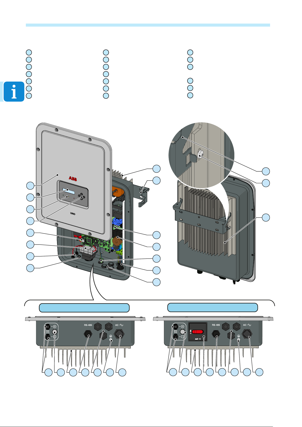
Reference number index
Скачано с сайта интернет магазина https://axiomplus.com.ua/
01
, Bracket
02
, Locking screws
03
, Heat sink
04
, Anti-condensation valve
05
, Front cover
06
, LED panel
07
, Display
08
, Keyboard
09
, DC input connectors
10
, AC output connector
11
, Expansion board connector (J6)
12
, SD Card slot
13
, Signals terminal block
14
, RS485 connector
Graphical representation of references
15
,
RS485 termination line jumper
16
, DC disconnect switch
17
, Fastening points for Stand Alone
board
18
, Stand-alone board (optional)
19
, External earth connection
20
, Service cable glands
05
07
06
08
12
16
09
04
UP
ESC
POWER
ALARM
ENTER
GFI
DOWN
UNO-2.0/3.0/3.6/4.2-TL-OUTD
03
01
17
18
14
10
20
01
02
03
UNO-2.0/3.0/3.6/4.2-TL-OUTD-S
09 04 03 14 20 19 10
09 04 03 1416 20 19 10
000467AG
- 8 -

1- Introduction and general information
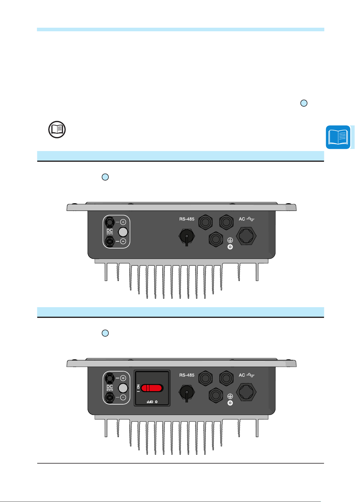
UNO-2.0/3.0-TL-OUTD-S
Скачано с сайта интернет магазина https://axiomplus.com.ua/
1120131416 15040912 1810
UNO-3.6/4.2-TL-OUTD-S
000467AG
1120131416 15040912 1810
- 9 -
1- Introduction and general information
The document and intended audience
Скачано с сайта интернет магазина https://axiomplus.com.ua/
Purpose and structure of the document
This operating and maintenance manual is a useful guide that will enable
you to work safely and carry out the operations necessary for keeping the
equipment in good working order.
If the equipment is used in a manner not specied in the installer manual, the protection
provided by the equipment may be impaired.
The language in which the document was originally written is ITALIAN; therefore, in the event
of inconsistencies or doubts please ask the manufacturer for the original document.
List of annexes
In addition to this operating and maintenance manual, (if applicable or on
request) the following enclosed documentation is supplied:
- EC declaration of conformity
- quick installation guide
CAUTION: Part of the information given in this document is taken from the original documents provided by the suppliers. This document contains only the information considered
necessary for the use and routine maintenance of the equipment.
Staff characteristics
The Customer must make sure that the operator has the necessary skills and training to do
his/her job. The staff in charge of using and maintaining the equipment must be experienced,
aware and responsible enough to perform the tasks described and must reliably demonstrate
their ability to interpret what is described in the manual correctly.
For safety reasons, only a qualied electrician who has received training and/or demonstrated skills and knowledge on the structure and operation of the unit may install the inverter.
The installation must be performed by qualied installers and/or licensed electricians in accordance with the existing regulations in the country of installation.
The employment of a person who is NOT qualied, is drunk, or on narcotics, has a prosthetic
mitral valve or a pacemaker is strictly forbidden.
The customer has civil liability for the qualication and mental or physical state of the pro-
fessional gures who interact with the equipment. They must always use the personal pro-
tective equipment provided for by the laws of the country of destination and whatever else is
provided by their employer.
000004EG
- 10 -

1- Introduction and general information
Symbols and signs
Скачано с сайта интернет магазина https://axiomplus.com.ua/
In the manual and/or in some cases on the equipment, the danger or
hazard zones are indicated with signs, labels, symbols or icons.
Symbol Description
Indicates that it is mandatory to consult the manual or original document,
which must be available for future use and must not be damaged in any
way.
General warning - Important safety information. Indicates operations or
situations in which staff must be very careful.
Dangerous Voltage - Indicates operations or situations in which staff
must be very careful with regard to dangerous voltage levels.
Hot parts - Indicates a risk arising from the presence of hot zones or
zones with parts at high temperatures (risk of burns).
Risk of explosion
IPXX
Risk of injury due to the weight of the equipment. Take care during lifting
and transport
Indicates that the area in question must not be accessed or that the
operation described must not be carried out.
Keep out of the reach of children
Indicates that smoking and the use of naked ames is prohibited.
Indicates that it is mandatory to carry out the described operations
using the clothing and/or personal protective equipment provided by the
employer.
WEEE logo. Indicates that the product is to be disposed of according to
current legislation regarding the disposal of electronic components.
Indicates the protection rating of the equipment according to IEC 70-1
(EN 60529 June 1997) standard.
000006GG
Point of connection for grounding protection.
Indicates the permitted temperature range
- 1 1 -

1- Introduction and general information
Symbol Description
5
10
Скачано с сайта интернет магазина https://axiomplus.com.ua/
Indicates a risk of electric shock. Stored energy discharge time: 5 minutes
Indicates a risk of electric shock. Stored energy discharge time: 10
minutes
DC
AC
Direct Current
Alternating current
With insulation transformer
Without insulation transformer
Positive pole of the input voltage (DC)
Negative pole of the input voltage (DC)
Indicates the centre of gravity of the equipment.
Indicates the requirement to wear acoustic protection devices in order to
prevent damage to hearing
000006GG
- 12 -

1- Introduction and general information
Field of use, general conditions
Скачано с сайта интернет магазина https://axiomplus.com.ua/
ABB accepts no liability for damage of any kind that may arise from incorrect or careless operations.
You may not use the equipment for a use that does not conform to that provided for in the
eld of use. The equipment MUST NOT be used by inexperienced staff, or even experienced
staff if carrying out operations on the equipment that fail to comply with the indications in this
manual and enclosed documentation.
Intended or allowed use
This equipment is a string inverter designed to:
suitable for feeding into the public distribution network.
Limits in field of use
The inverter can be used only with photovoltaic modules which have ground isolated input
poles, unless they are accessories installed that enable grounding of the inputs. In this case
you must install an insulating transformer on the AC side of the system.
Only a photovoltaic generator can be connected in the input of the inverter (do not connect
batteries or other sources of power supply).
The inverter can be connected to the electricity grid only in countries for which it has been
certied/approved.
The inverter cannot be connected to the DC side in parallel to other inverters to convert energy from a photovoltaic generator with a power greater than the nominal power of the single
inverter.
The inverter may only be used in compliance with all its technical characteristics.
transform a direct current (DC)
supplied by a photovoltaic generator (PV)
in an alternating electrical current (AC)
Improper or prohibited use
IT IS STRICTLY FORBIDDEN TO:
• Install the equipment in environments with particular ammability conditions or in adverse or
disallowed environmental conditions (temperature and humidity).
• Use the equipment with safety devices which are faulty or disabled.
• Use the equipment or parts of the equipment by linking it to other machines or equipment,
unless expressly provided for.
• Modify operating parameters that are not accessible to the operator and/or parts of the
000007CG
equipment to vary its performance or change its insulation.
• Clean the equipment with corrosive products that may corrode parts or generate electrostatic charges.
• Use or install the appliance or parts of it without having read and understood the contents of
the user and maintenance manual.
• Warm or dry rags and clothes on parts at temperature. In addition to being hazardous, doing
so would compromise component ventilation and cooling.
- 13 -

General conditions
Скачано с сайта интернет магазина https://axiomplus.com.ua/
Characteristics
2
The characteristics of the equipment are described so that its main
components can be identied and the technical terminology used in the
manual can be explained.
Technical terminology and the fast information retrieval system, are
supported by:
• Table of contents
• Reference number index
The Characteristics chapter contains information about the models,
details of the equipment, characteristics and technical data, overall
dimensions and identication of the equipment itself.
The customer/Installer takes full responsibility if, when reading this manual, the chronological
order of its presentation established by the manufacturer is not observed. All information is
provided and occasional reference may be made to information in previous chapters.
In certain cases, there may be a need to separately document software
functionality or attach supplementary documentation to this manual
intended for more qualied professional gures.
000008EG
- 14 -
2 - Characteristics
Models and range of equipment
Скачано с сайта интернет магазина https://axiomplus.com.ua/
The models of single-phase inverters covered by this manual are divided
into four groups according to their maximum output power:
2.0kW, 3.0 kW, 3.6 kW or 4.2 kW.
For inverters of equal output power the variant between the various models is the presence or lack thereof of the DC disconnect switch
The choice of the inverter model must be made by a qualied technician who knows about
the installation conditions, the devices that will be installed outside the inverter and possible
integration with an existing system.
• UNO-2.0/3.0/3.6/4.2-TL-OUTD MODELS
• Number of input channels: 1
• DC disconnect switch
• Input connectors: quick-t connectors (1 pair)
16
: No
16
• UNO-2.0/3.0/3.6/4.2-TL-OUTD-S MODELS
• Number of input channels: 1
• DC disconnect switch
• Input connectors: quick-t connectors (1 pair)
000468AG
16
: Yes
- 15 -

2 - Characteristics
Identification of the equipment and manufacturer
MODEL:
UNO-2.0-TL-OUTD
IP65
5 minutes
-25 to + 60 °C
-13 to +140 °F
INVERTERSOLAR
www.abb.com/solar
600 V
80 - 580 V
12.5 A
180 - 500 V
16 A
230 V 1Ø
50 Hz
1800 W @ 45 °C amb.
2000 W @ 45 °C amb.
10 A
2000 VA
V
dc max
I
dc max
V
dc MPP
V
dc, Full Power
I
sc max
V
acr
f
r
I
ac max
Pacr (cos =
±
0.9)
φ
P
acr (cos = 1)
φ
S
max
Made in Italy
DIN V VDEV 0126-1-1
PROTECTIVE CLASS: I
MODEL:
UNO-3.6-TL-OUTD
IP65
5 minutes
-25 to + 60 °C
-13 to +140 °F
INVERTERSOLAR
www.abb.com/solar
850 V
350 - 820 V
11 A
380 - 700 V
15 A
230 V 1Ø
50 Hz
3240 W @ 45 °C amb.
3600 W @ 45 °C amb.
16 A
3600 VA
V
dc max
I
dc max
V
dc MPP
V
dc, Full Power
I
sc max
V
acr
f
r
I
ac max
Pacr (cos =
±
0.9)
φ
P
acr (cos = 1)
φ
S
max
Made in Italy
DIN V VDEV 0126-1-1
PROTECTIVE CLASS: I
MODEL:
UNO-3.0-TL-OUTD
IP65
5 minutes
-25 to + 60 °C
-13 to +140 °F
INVERTERSOLAR
www.abb.com/solar
600 V
80 - 580 V
16 A
200 - 500 V
20 A
230 V 1Ø
50 Hz
2700 W @ 45 °C amb.
3000 W @ 45 °C amb.
15 A
3000 VA
V
dc max
I
dc max
V
dc MPP
V
dc, Full Power
I
sc max
V
acr
f
r
I
ac max
Pacr (cos =
±
0.9)
φ
P
acr (cos = 1)
φ
S
max
Made in Italy
DIN V VDEV 0126-1-1
PROTECTIVE CLASS: I
MODEL:
UNO-4.2-TL-OUTD
IP65
5 minutes
-25 to + 60 °C
-13 to +140 °F
INVERTERSOLAR
www.abb.com/solar
850 V
350 - 820 V
12.5 A
380 - 700 V
15 A
230 V 1Ø
50 Hz
3780 W @ 45 °C amb.
4200 W @ 45 °C amb.
20 A
4200 VA
V
dc max
I
dc max
V
dc MPP
V
dc, Full Power
I
sc max
V
acr
f
r
I
ac max
Pacr (cos =
±
0.9)
φ
P
acr (cos = 1)
φ
S
max
Made in Italy
DIN V VDEV 0126-1-1
PROTECTIVE CLASS: I
Скачано с сайта интернет магазина https://axiomplus.com.ua/
The technical data provided in this manual does not substitute the data
supplied on the labels afxed to the equipment.
The labels afxed to the equipment must NOT be removed, damaged, stained, hidden, etc.,
for any reason whatsoever.
The approval label contains the following information:
1. Manufacturer
2. Model
3. Rating data
4. Certication marks
The labels are NOT to be hidden by foreign objects and parts (rags, boxes, equipment, etc.);
they must be regularly cleaned and always kept in sight.
1
2
3
1
2
3
4
4
3
3
- 16 -
1
1
4
2
4
2
000468AG

2 - Characteristics
Besides the label with the specications, an additional inverter identica-
Скачано с сайта интернет магазина https://axiomplus.com.ua/
tion label is also provided.
The label displays the following information:
ABB
UNO-X.X-TL-OUTD-Y
The ofcially required information is located on the approval label. The identication label is
an accessory label which shows the information necessary for the identication and charac-
terisation of the inverter by ABB.
Note: The labels are NOT to be hidden by foreign objects and parts (rags, boxes, equipment,
etc.); they must be regularly cleaned and always kept in sight.
P/N:PPPPPPPPPPP
SN:YYWWSSSSSS WK:WWYY
WO:XXXXXXX
SO:SXXXXXXXX Q1
• Inverter model
- X.X = Inverter power rating:
- Y = Integrated disconnect switch
• Inverter Part Number
• Inverter Serial Number consisting of:
- YY = Year of manufacture
- WW = Week of manufacture
- SSSSSS = sequential number
• Week/Year of manufacture
000468AG
- 17 -

2 - Characteristics
Characteristics and technical data
Скачано с сайта интернет магазина https://axiomplus.com.ua/
UNO-2.0-TL-OUTD UNO-3.0-TL-OUTD
Input
Absolute Maximum Input Voltage (Vmax,abs) 600 V
Input start-up voltage (Vstart) 100...300 V (default 150 V)
Input operating interval (Vdcmin...Vdcmax) 0.7xVstart...580 V (min 80V)
Rated Input Voltage (Vdcr) 400 V
Input Nominal Power(Pdcr) 2200 W 3200 W
Number of Independent MPPT 1
Maximum input power
(PMPPTmax)
DC Voltage MPPT Interval
(VMPPTmin ... VMPPTmax) to Pacr
Maximum DC Input Current (Idcmax) 12.5 A 16.0 A
Maximum Return current (AC side vs DC side) < 5 mA
Maximum short circuit current (Iscmax) 15.0 A 20.0 A
Number of DC Connection Pairs in Input
Type of Input DC Connectors Quick-t PV connector
Type of photovoltaic panels that can be connected
at input according to IEC 61730
Input protection
Reverse Polarity Protection Yes, from current limited source
Input overvoltage protection
- Varistors
Insulation Check Complying with the local standard
Characteristics of DC disconnect switch (Version
-S)
Output
AC Connection to the grid Single phase
Nominal Output Power (Pacr @cosφ=1) 2000 W 3000 W
Maximum Output Power (Pacmax @cosφ=1) 2000 W 3000 W
Maximum apparent Output power (Smax) 2000 VA 3000 VA
Rated AC Output Voltage (Vacr) 230 V
Output voltage range (Vacmin...Vacmin) 180...264 V
Maximum output current (Iacmax) 10.0 A 15.0 A
Maximum fault current 18.3 A rms (200ms)
Contribution to short-circuit current 12.0 A 17.0 A
Inrush current Negligible
Rated Output Frequency (fr) 50 / 60 Hz
Output Frequency Range (fmin...fmax) 47...53 Hz / 57…63 Hz
Nominal power factor
and setting interval
Total Current Harmonic Distortion <3%
AC Connections Type Female connector from panel
Output protection
Anti-islanding Protection Complying with the local standard
Maximum AC overcurrent protection 16.0 A 20.0 A
Output overvoltage protection - Varistors 2 (L - N / L - PE)
Operating performance
Maximum Efciency (ηmax) 97.3%
Weighted Efciency (EURO/CEC) 96.0% / -
Power Supply Threshold 8.0 W
Night-time consumption < 0.1W
2200 W 3200 W
180...500 V 200...500 V
(3)
1
Class A
Yes
Max. 25 A / 600 V
(1)
> 0.995
adj. ± 0.8 at maximum Smax
(4)
(2)
000469AG
- 18 -

2 - Characteristics
UNO-2.0-TL-OUTD UNO-3.0-TL-OUTD
Скачано с сайта интернет магазина https://axiomplus.com.ua/
Communication
Remote Monitoring VSN300 Wi Logger Card (opt..), VSN700 Data Logger (opt.)
Wireless local monitoring VSN300 Wi Logger Card (opt.)
User Interface LCD Display with 16 characters x 2 lines
Wired local monitoring PVI-USB-RS232_485 (opt.)
Available ports RS485, Remote ON/OFF, Alarm Relay
Expansion slot 1
Environmental
Ambient temperature
Relative Humidity 0...100% w/o condensation
Typical noise emission pressure 50 dB(A) @ 1 m
Maximum operating altitude without derating 2000 m / 6560 ft
Environmental pollution degree
classication for external environments
Environmental category Outdoor
Physical
Environmental Protection Rating IP 65
Cooling System Natural
Dimensions (H x W x D) 553mm x 418mm x 175mm / 21.8” x 16.5” x 6.9”
Weight 12 kg / 26.5 lb
Assembly System Wall bracket
Overvoltage rating as per IEC 62109-1 II (DC input) III (AC output)
Safety
Safety class I
Insulation Level Without transformer (TL)
CE Marking (50 Hz Only)
Safety and EMC Standards
IEC/EN 62109-1, IEC/EN 62109-2, EN 61000-6-2, EN 61000-6-3,
Other features
Function for managing loads GoGo Relay
-25...+ 60 °C/-13...140 °F
with derating above 45°C / 113°F
3
EN 61000-3-2, EN 61000-3-3
1. The output voltage range may vary according to the grid standard of the country of installation
2. The output frequency range may vary according to the grid standard of the country of installation
3. In the event of a fault, limited by the external protection envisaged on the AC circuit
4. Please refer to the document “String inverters – Product manual appendix” available at www.abb.com/solarinverters for informa-
tion on the quick-t connector brand and model used in the inverter
Note. Features not specically mentioned in this data sheet are not included in the product
.
000469AG
- 19 -

2 - Characteristics
UNO-3.6-TL-OUTD UNO-4.2-TL-OUTD
Скачано с сайта интернет магазина https://axiomplus.com.ua/
Input
Absolute Maximum Input Voltage (Vmax,abs) 850 V
Input start-up voltage (Vstart) 300…600 V (default 380 V)
Input operating interval
(Vdcmin...Vdcmax)
Rated Input Voltage (Vdcr) 500 V 600 V
Input Nominal Power(Pdcr) 3900 W 4500 W
Number of Independent MPPT 1
Maximum input power (PMPPTmax) 3900 W 4500 W
DC Voltage MPPT Interval
(VMPPTmin ... VMPPTmax) to Pacr
Maximum DC Input Current (Idcmax) 1 1.0 A 12.5 A
Maximum Return current (AC side vs DC side) 4.7 A
Maximum short-circuit current 15.0 A
Number of DC Connection Pairs in Input
Type of Input DC Connectors Quick-t PV connector
Type of photovoltaic panels that can be connec-
ted at input according to IEC 61730
Input protection
Reverse Polarity Protection Yes, from current limited source
Input overvoltage protection -
Varistors
Insulation Check Complying with the local standard
Characteristics of DC disconnect switch (Version
-S)
Output
AC Connection to the grid Single phase
Nominal Output Power (Pacr @cosφ=1) 3600 W 4200 W
Maximum Output Power (Pacmax @cosφ=1) 3600 W 4200 W
Maximum apparent Output power (Smax) 3600 VA 4200 VA
Rated AC output voltage (Vacr) 230 V
Output voltage range (Vacmin...Vacmin) 180...264 V
Maximum output current (Iacmax) 16.0 A 20.0 A
Maximum fault current 22.9 A rms (20ms)
Contribution to short-circuit current 18.0 A 22.0 A
Inrush current Negligible
Rated Output Frequency (fr) 50 / 60 Hz
Output Frequency Range (fmin...fmax) 47...53 Hz / 57…63 Hz
Nominal power factor and setting interval
adj. ± 0.8 at maximum Smax
Total Current Harmonic Distortion <3%
AC Connections Type Female connector from panel
Output protection
Anti-islanding Protection Complying with the local standard
Maximum AC overcurrent protection
20.0 A 25.0 A
Output Overvoltage Protection
- Varistors
Operating performance
Maximum Efciency (ηmax) 98.4%
Weighted Efciency (EURO/CEC) 97.5% / -
Power Supply Threshold 8.0 W
Night-time consumption < 0.1W
350...820V
380...700 V
(3)
1
(4)
Class A
Yes
Max. 16 A / 1000 V
(1)
(2)
> 0.995
2 (L - N / L - PE)
000469AG
- 20 -

2 - Characteristics
UNO-3.6-TL-OUTD UNO-4.2-TL-OUTD
Скачано с сайта интернет магазина https://axiomplus.com.ua/
Communication
Remote Monitoring VSN300 Wi Logger Card (opt.), VSN700 Data Logger (opt.)
Wireless local monitoring VSN300 Wi Logger Card (opt.)
User Interface LCD Display with 16 characters x 2 lines
Wired local monitoring PVI-USB-RS232_485 (opt.)
Available ports RS485, Remote ON/OFF, Alarm Relay
Expansion slot 1
Environmental
Ambient temperature
Relative Humidity 0...100% w/o condensation
Typical noise emission pressure 50 dB(A) @ 1 m
Maximum operating altitude without derating 2000 m / 6560 ft
Environmental pollution degree
classication for external environments
Environmental category Outdoor
Physical
Environmental Protection Rating IP 65
Cooling System Natural
Dimensions (H x W x D) 553mm x 418mm x 175mm / 21.8” x 16.5” x 6.9”
Weight 12 kg / 26.5 lb
Assembly System Wall bracket
Overvoltage rating as per IEC 62109-1 II (DC input) III (AC output)
Safety
Safety class I
Insulation Level Without transformer (TL)
CE Marking (50 Hz Only)
Safety and EMC Standards
EN 50178, IEC/EN 62109-1, IEC/EN 62109-2, EN 61000-6-2,
EN 61000-6-3, EN 61000-3-2, EN 61000-3-3
Other features
Function for managing loads GoGo Relay
-20...+ 60 °C/-13...140 °F
with derating above 45°C / 113°F
3
1. The output voltage range may vary according to the grid standard of the country of installation
2. The output frequency range may vary according to the grid standard of the country of installation
3. In the event of a fault, limited by the external protection envisaged on the AC circuit
4. Please refer to the document “String inverters – Product manual appendix” available at www.abb.com/solarinverters for informa-
tion on the quick-t connector brand and model used in the inverter
Note. Features not specically mentioned in this data sheet are not included in the product
.
000469AG
- 21 -

2 - Characteristics
Tightening torques
553mm - 21.77”
Скачано с сайта интернет магазина https://axiomplus.com.ua/
T o maintain the IP65 protection of the system and for optimal installation,
the following tightening torques must be used:
AC output connector cable gland 10 (ring nut fastening)
Screws for securing AC output connector cables gland
Service cable glands
Service cable glands
Front cover fastening screws
RS485 connector cable gland
Locking screws
Screw for external ground connection
Overall dimensions
The overall dimensions are expressed in millimetres and inches and include the wall installation bracket.
02
20
M20 (ring nut fastening)
20
M20 (lock nut fastening)
05
14
(ring nut fastening)
19
4...5 Nm
0.8...1 Nm
2.5 Nm
7.0 Nm
2.5 Nm
0.8 Nm
2.5 Nm
2.5 Nm
UP
ESC
POWER
ALARM
ENTER
GFI
DOWN
418mm - 16.45”
- 22 -
175mm
6.89”
000469AG
2 - Characteristics
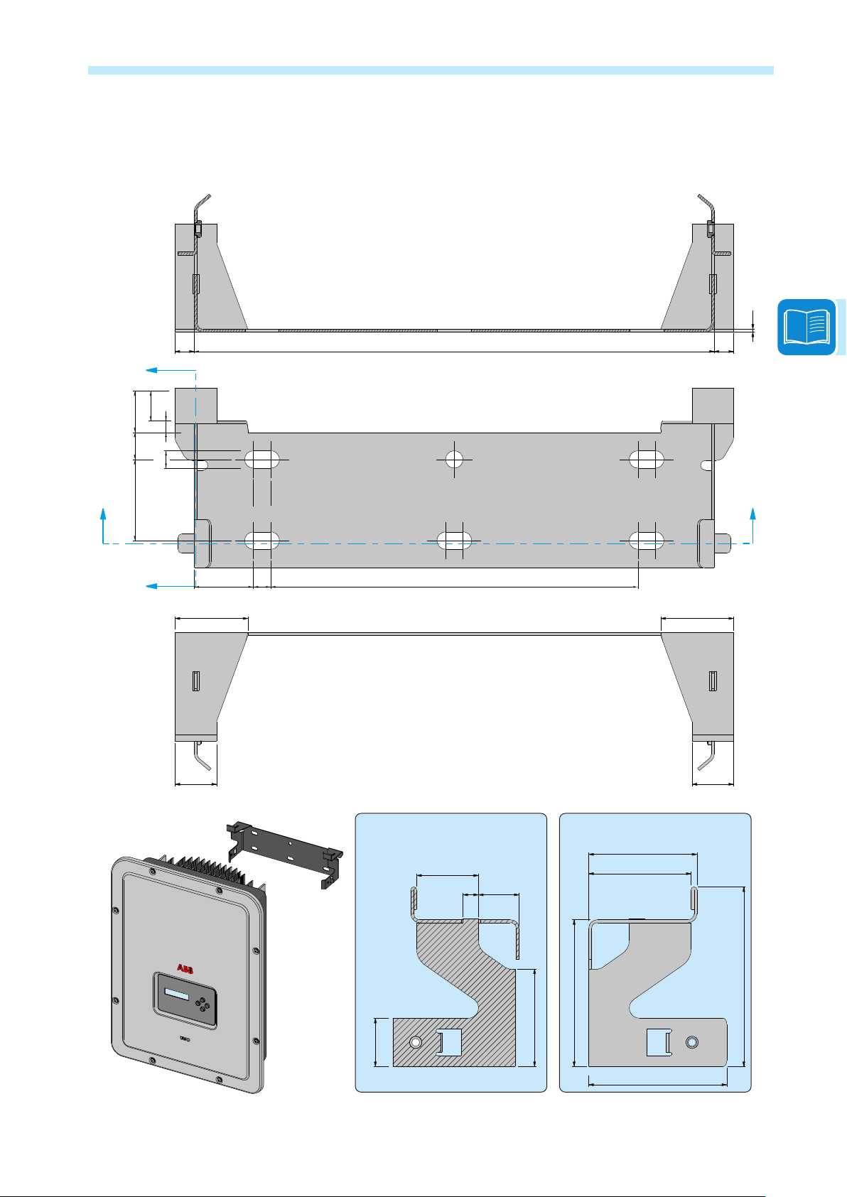
Bracket dimensions
Скачано с сайта интернет магазина https://axiomplus.com.ua/
The dimensions of the wall mounting bracket are expressed in
mm and inches.
1.5
10
269±0.3
10
A
15.5
21.5
6
14
9
42
B
A
30.5 9
37.7 37.7
190
B
000469AG
25
- 23 -
32
21.521.5
B-BA-A
56
53
218
93
76
50.5
71.4

2 - Characteristics
Efficiency curves
Скачано с сайта интернет магазина https://axiomplus.com.ua/
The efciency curves are linked to technical parameters that are continually being developed
and improved and should therefore be considered approximate.
The equipment was designed considering current energy conservation
standards, to avoid waste and unnecessary leakage.
Graphs of the efciency curves of all models of inverter described in this
manual are shown below.
UNO-2.0-TL-OUTD
UNO-2.0-TL-OUTD-S
UNO-3.0-TL-OUTD
UNO-3.0-TL-OUTD-S
UNO-2.0-TL-OUTD - Efficiency Curves
98
96
94
92
90
Efficiency [%]
88
86
84
0% 10% 20% 30% 50% 70% 100%
% of rated Output Power
80% 90%60%40%
UNO-3.0-TL-OUTD - Efficiency Curves
98
200Vdc
360Vdc
480Vdc
96
94
92
90
Efficiency [%]
88
86
84
0% 10% 20% 30% 50% 70% 100%
% of rated Output Power
80% 90%60%40%
- 24 -
200Vdc
400Vdc
500Vdc
000470AG

2 - Characteristics
UNO-3.6-TL-OUTD - Efficiency Curves
84
82
86
88
90
92
94
96
98
100
0% 10% 20% 30% 50% 70% 100%
Efficiency [%]
360Vdc
600Vdc
700Vdc
80% 90%60%40%
% of rated Output Power
UNO-4.2-TL-OUTD - Efficiency Curves
84
86
88
90
92
94
96
98
100
0% 10% 20% 30% 50% 70% 100%
Efficiency [%]
360Vdc
600Vdc
700Vdc
80% 90%60%40%
% of rated Output Power
UNO-3.6-TL-OUTD
Скачано с сайта интернет магазина https://axiomplus.com.ua/
UNO-3.6-TL-OUTD-S
UNO-4.2-TL-OUTD
UNO-4.2-TL-OUTD-S
000470AG
- 25 -

2 - Characteristics
Power limitation (Power Derating)
Скачано с сайта интернет магазина https://axiomplus.com.ua/
In order to allow inverter operation in safe thermal and electrical conditions, the unit automatically reduces the value of the power fed into the
grid.
Power limiting may occur due to:
• Adverse environmental conditions (thermal derating)
• Percentage of output power (value set by the user)
• Grid voltage over frequency (mode set by user)
• Grid overvoltage U>10min Der. (enabling carried out by user)
• Anti-islanding
• High input voltage values
• High input current values.
Power reduction due to environmental conditions
The power reduction value and the inverter temperature at which it occurs depend on the ambient temperature and on many operating parameters. Example: input voltage, grid voltage and power available from
the photovoltaic eld.
The inverter can therefore reduce the power during certain periods of the
day according to the value of these parameters.
In any case, the inverter guarantees the maximum output power even at
high temperatures, provided the sun is not shining directly on it.
100%(Pacr)
90%
80%
70%
60%
50%
Pout (%)
40%
30%
20%
10%
Pout Vs Tamb @ Vnom
UNO-TL-2.0
UNO-TL-3.0
UNO-TL-4.2
UNO-TL-3.6
0
10
15
20
25
30
35
40
45
50
5
0
Ambient temperature (°C)
55
60
65
70
75
80
000470AG
- 26 -

2 - Characteristics
Power reduction due to the input voltage
Скачано с сайта интернет магазина https://axiomplus.com.ua/
The graphs show the automatic reduction of supplied power when input
voltage values are too high or too low.
PVI-2.0-TL-OUTD
PVI-2.0-TL-OUTD-S
PVI-3.0-TL-OUTD
PVI-3.0-TL-OUTD-S
PVI-3.6-TL-OUTD
PVI-3.6-TL-OUTD-S
PVI-4.2-TL-OUTD
PVI-4.2-TL-OUTD-S
Pout Vs Vin (single input channel)
4500
4000
3500
3000
2500
2000
Pout (kW)
1500
1000
500
0
100
150
200
250
300
350
50
0
400
Vin (V)
Pout Vs Vin (single input channel)
4500
4000
3500
3000
2500
2000
Pout (kW)
1500
1000
500
0
400
450
500
550
350
600
750
650
700
UNO-3.0-TL-OUTD
UNO-2.0-TL-OUTD
450
500
550
600
650
700
UNO-4.2-TL-OUTD
UNO-3.6-TL-OUTD
800
850
900
950
1000
1050
000470AG
Vin (V)
- 27 -

2 - Characteristics
Characteristics of a photovoltaic generator
Скачано с сайта интернет магазина https://axiomplus.com.ua/
A PV generator consists of an assembly of photovoltaic modules that
transform solar radiation into DC electrical energy and can be made up
of:
Strings: number (X) of PV modules connected in series
Array: group of X strings connected in parallel
Strings and Arrays
The string technology was developed to signicantly reduce the installation costs of a photovoltaic system, mainly associated to wiring on the
DC side of the inverter and subsequent distribution on the AC side. A
photovoltaic panel consists of many photovoltaic cells mounted on the
same support.
• A string consists of a certain number of panels connected in series.
• An array consists of two or more strings connected in parallel.
Large photovoltaic systems can include multiple arrays connected to one
or more inverters.
The greater the number of panels in each string, the lower the cost and
the less complex the wiring connections of the system.
CELL
The current of each array must fall within the limits of the inverter.
PANEL STRING ARRAY
+
_
+
_
000471AG
- 28 -

2 - Characteristics
Description of the equipment
Скачано с сайта интернет магазина https://axiomplus.com.ua/
This equipment is a string inverter which converts the direct current of a
photovoltaic generator into alternating current and feeds it into the public
distribution grid.
Photovoltaic panels convert solar radiation into “DC” electrical energy
(via a photovoltaic eld, also called PV generator); in order to use it, it
is transformed into “AC” alternating current. This conversion, known as
inversion from DC to AC, is done in an efcient way by the ABB inverters, without using any rotary elements, rather only via static electronic
systems.
In order to allow inverter operation in safe thermal and electrical conditions, the unit automatically reduces the value of the power fed into the
grid under adverse environmental conditions or unsuitable input voltage
values.
When connected in parallel with the grid, the alternating current from the
inverter ows directly into the domestic or industrial distribution circuit,
which is in turn connected to the public distribution grid.
This way the solar energy system compensates for the energy drawn
from the utilities connected to the grid to which it is linked.
When the photovoltaic system is not generating sufcient energy, the
power required to ensure proper operation of connected loads is taken
from the public distribution grid. While if too much energy is produced, it
is directly fed to the grid, thus becoming available to other users.
According to national and local standards and regulations the produced
energy can be sold to the grid or credited to the user against future consumption, thus granting a great saving of money.
Panels
000472AG
PV
Operating diagram
DC Disconnect
switch/es
Inverter
AC safety devices
(Thermal-magnetic.
differential)
- 29 -
Grid
distributor
Grid

2 - Characteristics
Mutual connection of multiple inverters
Скачано с сайта интернет магазина https://axiomplus.com.ua/
If the photovoltaic system exceeds the capacity of a single inverter, it is
possible to connect multiple inverters to the system, each of them in turn
connected on the DC side to an appropriate section of the photovoltaic
generator, and on the AC side to the distribution grid.
Each string inverter will work independently of the others and its own
photovoltaic module will supply the maximum power available to the grid.
Notes on the system sizing
Decisions on how to structure a photovoltaic system depend on a series of factors and considerations, such as the type of panels, the space availability, the future location of the system, energy production goals over the long term, etc.
A conguration program that can help to correctly size the photovoltaic
system is available on the ABB website (http://stringsizer.abb.com).
000472AG
- 30 -
 Loading...