

Page 1
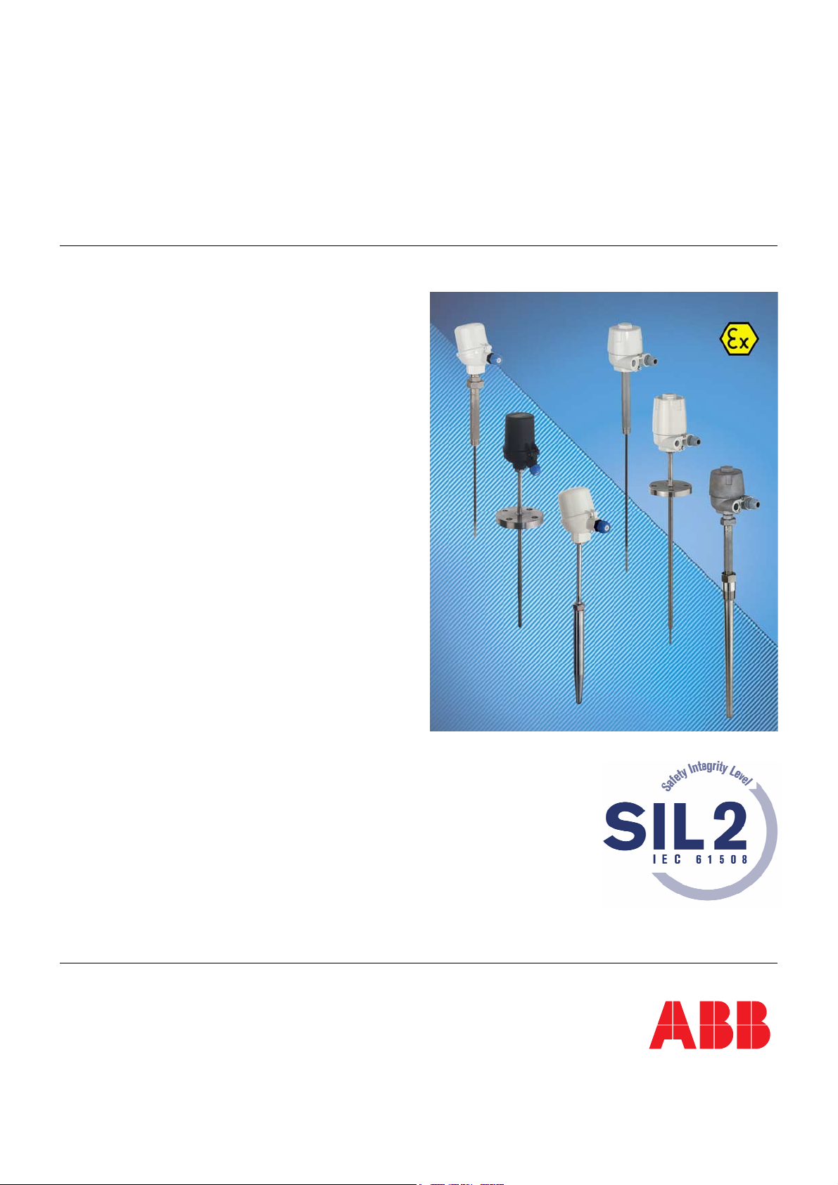
SIL-Safety Instructions
SM/TSP/SIL-EN
Temperature Sensors
SensyTemp TSP
Information regarding functional safety
Page 2

Blinder Text
Temperature Sensors
SensyTemp TSP
SIL-Safety Instructions
SM/TSP/SIL-EN
05.2007
Manufacturer:
ABB Automation Products GmbH
Borsigstraße 2
63755 Alzenau
Germany
Tel.: +49 551 905-534
Fax: +49 551 905-555
[email protected]
Contents
© Copyright 2007 by ABB Automation Products GmbH
Subject to change without notice
This document is protected by copyright. It assists the user with the safe and efficient operation of the
device. The contents may not be copied or reproduced in whole or in excerpts without prior approval of
the copyright holder.
2 SensyTemp TSP SM/TSP/SIL-EN
Page 3

Contents
1
Field of Application .............................................................................................................................................4
2 Acronyms and abbreviations.............................................................................................................................4
3 Relevant standards .............................................................................................................................................6
4 Other applicable documents and papers..........................................................................................................6
5 Terms and definitions .........................................................................................................................................7
6 Safety function.....................................................................................................................................................8
6.1 Overview ........................................................................................................................................................8
6.2 SensyTemp TSP temperature sensors with TTH300 transmitter ..................................................................8
6.3 SensyTemp temperature sensors without transmitter ...................................................................................9
7 Periodic checks .................................................................................................................................................10
7.1 SensyTemp TSP temperature sensors with TTH300 transmitter ................................................................10
7.2 SensyTemp temperature sensors without transmitter .................................................................................11
8 Repairs................................................................................................................................................................11
9 Configuration with TTH300 transmitters.........................................................................................................12
10 Safety engineering parameters........................................................................................................................15
11 Appendix ............................................................................................................................................................17
12 Management Summary FMEDA .......................................................................................................................18
SM/TSP/SIL-EN SensyTemp TSP 3
Page 4
Field of Application
1 Field of Application
Temperature monitoring of solids, fluids and gases of all types in containers and pipes
according to the special safety engineering requirements of IEC 61508.
The operating limits are defined in the data sheets and operating instructions for the separate
models. In case of questions, please contact your ABB partner.
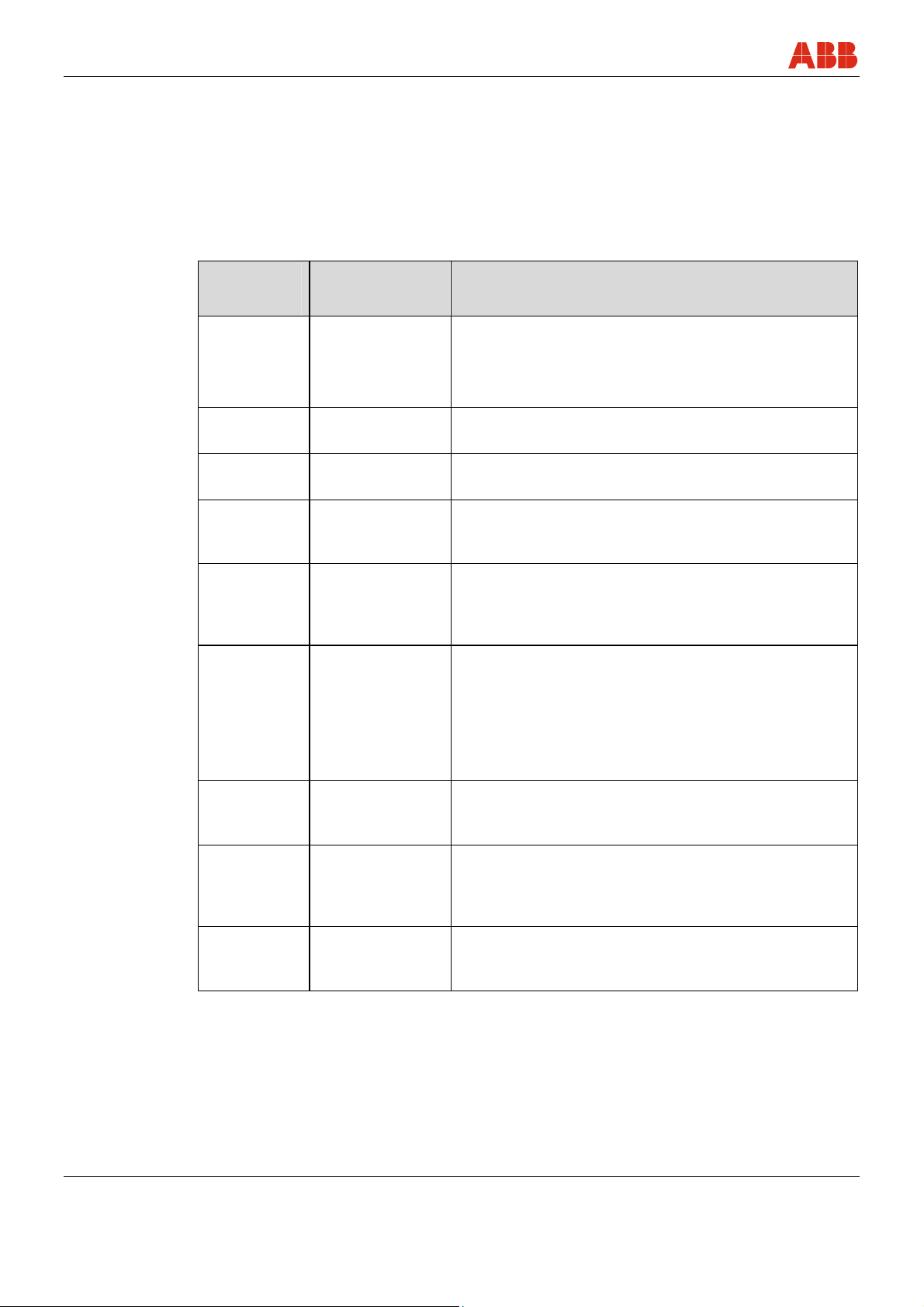
2 Acronyms and abbreviations
Acronym /
Abbreviation
Designation Description
HFT Hardware Fault
Tolerance
The hardware fault tolerance of the device.
This is the capability of a functional unit to continue the
execution of the demanded function in case of faults or
deviations.
MTBF Mean Time
This is the mean time period between two failures.
Between Failures
MTTR Mean Time To
Repair
PFD Probability of
Failure on
This is the mean time period between the occurrence of
a failure in a device or system and its repair.
This is the likelihood of dangerous safety function
failures occurring on demand.
Demand
PFDAVG Average
Probability of
This is the average likelihood of dangerous safety
function failures occurring on demand.
Failure on
Demand
SIL Safety Integrity
Level
The international standard IEC 61508 specifies four
discrete safety integrity levels (SIL 1 to SIL 4). Each
level corresponds to a specific probability range
regarding the failure of a safety function. The higher the
safety integrity level of the safety-related systems, the
lower likelihood of non-execution of the demanded
safety functions.
SFF Safe Failure
Fraction
The fraction of non-hazardous failures, i.e. the fraction of
failures without the potential to set the safety-related
system to a dangerous or impermissible state.
Low demand
mode
Low demand
mode of
operation
Measuring mode with low demand rate. Measuring
mode, in which the demand rate for the safety-related
system is not more than once a year and is not greater
than double the frequency of the periodic test.
DCS Distributed
Control System
Control systems that are used in industrial engineering
applications to monitor and control distributed
equipment.
4 SensyTemp TSP SM/TSP/SIL-EN
Page 5

Acronyms and abbreviations
Acronym /
Abbreviation
HMI Human Machine
DTM Device Type
LRV Device
URV Device
Multidrop Multidrop mode In multidrop mode, up to 15 field devices are connected
Designation Description
Here, the HMI is the combined module consisting of
Interface
Manager
Configuration
Configuration
LCD and local keypad.
The DTM is a software module that provides functions
for accessing device parameters, configuring and
operating the devices and diagnosing problems. By
itself, a DTM is not executable software. It only 'comes
to life' in an so called FDT 'container' program.
Lower Range Value of the measurement range
Upper Range Value of the measurement range
in parallel to a single wire pair. The analog current signal
serves just to energize the two-wire devices providing a
fixed current of 4mA.
SM/TSP/SIL-EN SensyTemp TSP 5
Page 6
Relevant standards
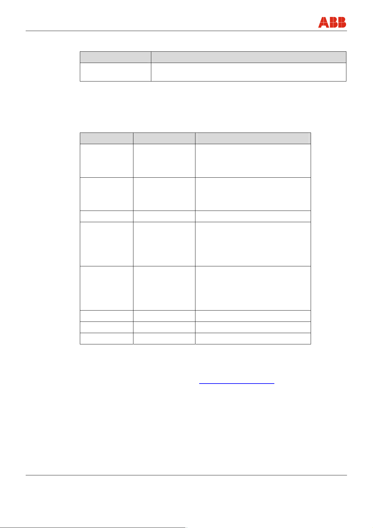
3 Relevant standards
Standard Designation
IEC 61508, Part 1 to 7 Functional safety of electrical/electronic/programmable electronic
safety-related systems
4 Other applicable documents and papers
Observe the following documents in addition to the safety information:
Product name Document name Designation and application
TSP111,
TSP121,
TSP131
TSP311,
TSP321,
TSP331
TSA101 DS/TSA101 Data Sheet TSA101
TSP111, TSP311
TSP121, TSP321
TSP131, TSP331
TSA101
DS/TSP1X1 Data Sheet TSP100
DS/TSP3X1 Data Sheet TSP300
OI/TSP Operating Instructions TSP 100,
TSP300 and TSA101
TSP111, TSP311
TSP121, TSP321
CI/TSP Commissioning Instructions TSP100,
TSP300 and TSA101
TSP131, TSP331
TSA101
TTH300 DS/TTH300 Data Sheet TTH300
TTH300 OI/TTH300 Operating Instructions TTH300
TTH300 CI/TTH300 Commissioning Instructions TTH300
Documents are available in the respective languages: -DE German, -EN English, -FR French,
etc.
These are available on the ABB internet at
www.abb.com/temperature.
In addition, the user of this device is responsible for ensuring compliance with the respective
legal regulations and standards.
6 SensyTemp TSP SM/TSP/SIL-EN
Page 7

Terms and definitions
5 Terms and definitions
Terms Definitions
Dangerous failure A failure that has the potential to place the safety-related system in
Safety-related system A safety-related system carries out the safety functions that are
a dangerous state or render the system inoperative.
required to achieve or maintain a safe state, e.g., for a system.
Example: A pressure meter, a logics unit (e.g., limit transmitter) and
a valve constitute a safety-related system.
Safety-related
functions
A specified function that is carried out by a safety-related system
with the goal, under consideration of a defined dangerous incident,
of achieving or maintaining a safe state for the system. Example:
limit temperature monitoring.
SM/TSP/SIL-EN SensyTemp TSP 7
Page 8
Safety function
6 Safety function
6.1 Overview
The temperature sensors in the SensyTemp TSP series can be used in applications according
to safety standards with the TTH300 transmitter or without a transmitter. Use the “CS” option
6.2 SensyTemp TSP temperature sensors with TTH300 transmitter
when ordering to select the safety version according to SIL Level 2.
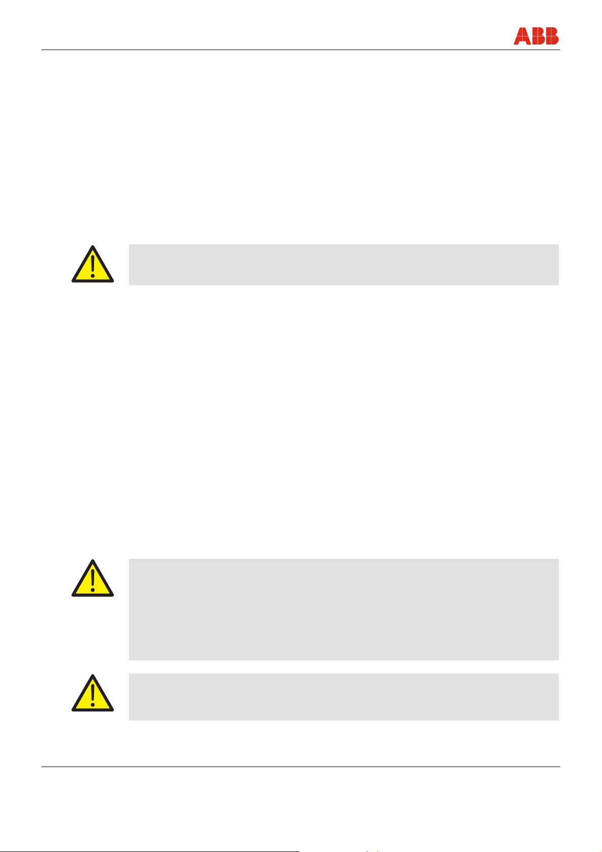
The SensyTemp temperature sensor with built-in TTH300 transmitter generates a linear
temperature signal proportional to the connected temperature sensor (4 … 20 mA). All safety
functions refer strictly to the analog output signal.
The entire valid range for the output signal must be configured between min. 3.8 mA and max.
20.5 mA (factory setting).
Warning!
In safety mode, HART communication occurs only when write protection is activated. The
HART master must comply with the safety requirements of the customer application.
Alarm behavior and current output
When a critical error is detected, the configured alarm current is generated and fed to a
downstream logics unit, e.g., a DCS, which checks for overshoots of a defined maximum value.
There are two selectable modes for the alarm current:
• HIGH ALARM (high alarm, max. alarm current); this is the factory setting
• LOW ALARM (low alarm, min. alarm current)
The low alarm current can be configured in a range from 3.5 to 4.0 mA. The factory setting is
3.6 mA.
The high alarm current can be configured in a range from 20.0 to 23.6 mA. The factory setting is
22 mA.
In the following cases, a detected error is displayed independently of the configured alarm
current within the low alarm range:
• Runtime errors
• Memory error (non-volatile data, RAM, ROM)
After switching on or restarting the transmitter electronic unit, the minimum low alarm time
(LOW-alarm, startup time) is 10 to 15 seconds.
Warning!
To ensure accurate error monitoring, the following conditions must be fulfilled:
• The low alarm must be configured to a value of ≤ 3.6 mA.
• The high alarm must be configured to a value of ≥ 21 mA.
• The DCS must identify the configured high and low alarms as malfunctions, and the alarm
must be configured according to the desired setup.
Warning!
To ensure the current output is functioning properly, the terminal on the standard device must
be between 11 V … 42 V DC (Ex version: 11 V … 30 V DC).
8 SensyTemp TSP SM/TSP/SIL-EN
Page 9
Safety function
The DCS loop must be capable of providing the required voltage level when the current output
is running with the configured high alarm.
The device does not meet safety requirements under the following conditions:
• During configuration
• When write protection is deactivated
• With activated HART multidrop mode
• During a simulation
• During an inspection of the safety function
Warning!
The safety function for the device includes the basic device TSPxxx with built-in TTH300
transmitter. Information in the corresponding documentation must be taken into consideration.
The percentage of failures that do not place the device in a hazardous functional state is
provided by the SFF value.
Total safety accuracy
The value defined for the overall accuracy of the safety function for this device is ± 2% of the
measuring range.
The basic accuracy depends on the sensor model and can be found in the appropriate data
sheets.
Switch-on time and safety operating mode
After switching on the device, all safety-relevant errors are detected after 2 minutes in low
demand mode.
6.3 SensyTemp temperature sensors without transmitter
SensyTemp TSP temperature sensors without transmitter provide an output signal suited to the
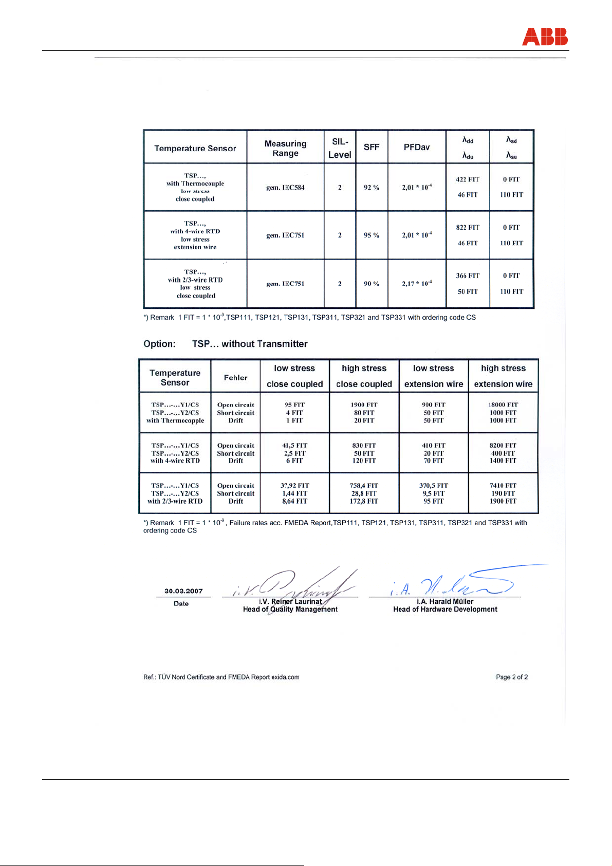
sensor (resistance or thermocouple). For failure rates based on the FMEDA report, refer to the
section “Safety Engineering Parameters”. These failure rates must be taken into consideration
when connecting to certified transmitters acc. to safety standards.
SM/TSP/SIL-EN SensyTemp TSP 9
Page 10

Periodic checks
7 Periodic checks
7.1 SensyTemp TSP temperature sensors with TTH300 transmitter
Safety inspections
The safety function for the entire safety loop must be checked regularly in accordance with IEC
61508. The inspection intervals are defined when calculating the individual safety loops for a
system.
Users are responsible for selecting the type of inspection and the intervals within the specified
period. The PFD
the SIL declaration of conformity, the inspection interval T[Proof] for checking the safety function
is 1 year. For additional inspection intervals with corresponding PFD
chapter “Management Summary FMEDA”.
Inspections must be conducted in a manner that enables users to verify proper function of the
safety equipment in combination with all components.
One possible procedure for recurring tests to detect hazardous and unidentified device errors is
described in the following section. Some 99% of the “Du” errors in the transmitter electronic unit
are detected by this test.
Checking the safety function
To check the safety function of the device, proceed as follows:
AV value depends on the selected inspection interval. For the PFDAV values in
AV values, refer to the
1. Bridge the safety DCS or take other appropriate measures to ensure the alarm is not
triggered unintentionally.
2. Deactivate write protection (refer to the relevant operating instructions).
3. Set the current output of the transmitter to a high alarm value by using the DTM simulation
command (Diagnosis/Simulation/Current Output).
4. Check whether the current output signal reaches this value.
5. Set the current output of the transmitter to a low alarm value by using the DTM simulation
command.
6. Check whether the current output signal reaches this value.
7. Activate write protection (refer to the relevant operating instructions) and wait at least 20
seconds.
8. Restart by switching off the device.
9. Check the current output with reference temperature; set the LRV value (4 mA) and URV (20
mA) via 2-point calibration.
10. Remove the bridge from the safety DCS or use another method to restore the standard
operating mode.
11. After performing the test, the events must be documented and archived properly.
A suitable sensor simulator (PT100-simulator, Ref. voltage source) can be used to check the
transmitter electronic unit without sensor. Test the sensor according to SIL requirements for
customer applications. ABB temperature sensors are checked according to the quick check
(see next section).
10 SensyTemp TSP SM/TSP/SIL-EN
Page 11

Repairs
7.2 SensyTemp temperature sensors without transmitter
Perform quick tests of thermocouples and resistance thermometers as well as the associated
measuring circuits in the uninstalled state.
Instruments required:
• Millivolt meter
• Resistance meter or resistance bridge
• Isolation meter with 60 … 100 V voltage (all measurements at room temperature)
The following tests can be performed:
• Check opening and isolation at room temperature
• Locate wire breaks by “knocking”.
A thermocouple is regarded as functioning correctly when R < 20 Ω (wire > 0.5 mm Ø).
8 Repairs
The value depends on the wire cross section and the length. R
thermocouple).
= 110 MΩ (with isolated
isol
A resistance thermometer is regarded as functioning correctly when R >> 110 Ω (for Pt100),
> 100 MΩ.
R
isol
• The heating of the thermocouples or resistance thermometers to approx. 200 °C to 400 °C
(without temperature controls) allows for further conclusions to be drawn about interruptions,
reversed polarity (with thermocouples), too little isolation resistance, etc.
Note
The accuracy of temperature sensors according to the ISO 9000 requirements can only be
checked by comparison with a reference element. In most cases, the deinstallation and test in
a test oven are necessary.
Defective devices must be sent to ABB Service. The type of error and possible reason must
also be provided.
Use the original packaging or a suitably secure packaging for returning the device for repair or
for recalibration. Include the properly filled out return form (see attachment) with the device.
According to EC guidelines for hazardous materials, the owner of hazardous waste is
responsible for its disposal or must observe the following regulations for its shipping:
All delivered devices to ABB Automation Products GmbH must be free from any hazardous
materials (acids, alkali, solvents, etc.).
When ordering spare parts always provide the serial number of the device. This information is
located on the model plate of the original device.
Address:
ABB Automation GmbH
Service Department
Borsigstr. 2
D-63755 Alzenau
GERMANY
SM/TSP/SIL-EN SensyTemp TSP 11
Page 12

Configuration with TTH300 transmitters
9 Configuration with TTH300 transmitters
The device was configured and tested according to customer order.
The device can be additionally configured with the local HMI or DTM using the HART interface.
Other configuration tools such as mobile handheld terminals are not described in these
instructions.
During setup, proper operation of the device is not ensured.
Warning!
Inspections:
Before commissioning the device, check as part of the safety function whether the device
setup supports the safety function for the system.
Make sure that the proper device was installed at the correct measuring point.
Each time the device is updated as part of the safety function, e.g., changing the mounting
position for the device or modifying the setup, the safety function of the device must be
checked again.
After checking the safety function, the device must be write-protected to prevent unintended
changes to the setup, since every change to the measurement system or parameters could
affect the safety function.
To ensure safe operation, the device must be write-protected.
To do so, follow these steps:
Activate/deactivate write protection
1. Write protection using local HMI (human-machine interface).
Go to “Device Setup", “Write Protection” and then enter the password “0110” to activate write
protection and password "0110" to disable write protection. (see operating instructions)
2. Write protection via DTM
Go to “Device Setup” and select “Write Protection” to activate the function.
If the device is locked (write-protected), it cannot be configured. Write protection is applied
for the entire device. Enter the password “0110” to disable write protection.
12 SensyTemp TSP SM/TSP/SIL-EN
Page 13
Configuration with TTH300 transmitters
Warning!
Inspections:
Write protection must be checked as follows:
1. Lock via HMI (human-machine interface):
- Check whether the lock icon is displayed on the LCD display.
- Select the menu item “Fault Signaling” and make sure the edit icon is not displayed on
the LCD display.
- Press the Edit button to make sure that there is no response on the LCD display.
2. Lock via DTM:
- HMI available: Check whether described under item 1.
- No HMI available (check the write protection):
Go to <Device>,<Parametrize> Current Output / Damping and update the damping
value. Select “Save Device Data in Device” and check whether the message "Device is
write-protected" is displayed.
Warning!
The software write protection does not lock again automatically. It remains unlocked until it is
reset.
Diagnostic Setup
The diagnostic setup of the device meets safety requirements and includes the following error
detections:
• Sensorboard communication error
• Sensorboard error
• Sensorboard A/D converter error
• Measuring error device temperature
• Sensor limit value alarm upper and lower
• Sensor error Ch. 1 and Ch. 2
• Sensor configuration RTD,R with 2, 3, 4-wire breakage and short circuit
• Sensor configuration TC, mV with wire break
• Redundancy-Mode Ch1 and Ch2 with enabled drift, drift monitoring
SM/TSP/SIL-EN SensyTemp TSP 13
Page 14

Configuration with TTH300 transmitters
Configuration parameters with effect on the safety function
All configuration parameters that are changed via HMI, DTM EDD or HART communication for
disabled write protection have an effect on the safety function of the device. The parameters are
described in the operating instructions. The safety function is checked according to the SIL
safety manual.
For redundancy mode with drift monitoring, the following parameters must be set in DTM, EDD:
• Sensor type-Freestyle characteristics and Callendar van Dusen
When using these two configurations, it is necessary to check at least 3 reference points
to verify the configured characteristic. For complex curves, check several sampling points
according to complexity.
• Redundancy mode
• Pulse output enabled
• Pulse time 60 s, continuous pulse
• Drift value Configured acc. to customer application
• Drift duration max. 120 s.
14 SensyTemp TSP SM/TSP/SIL-EN
Page 15
Safety engineering parameters
10 Safety engineering parameters
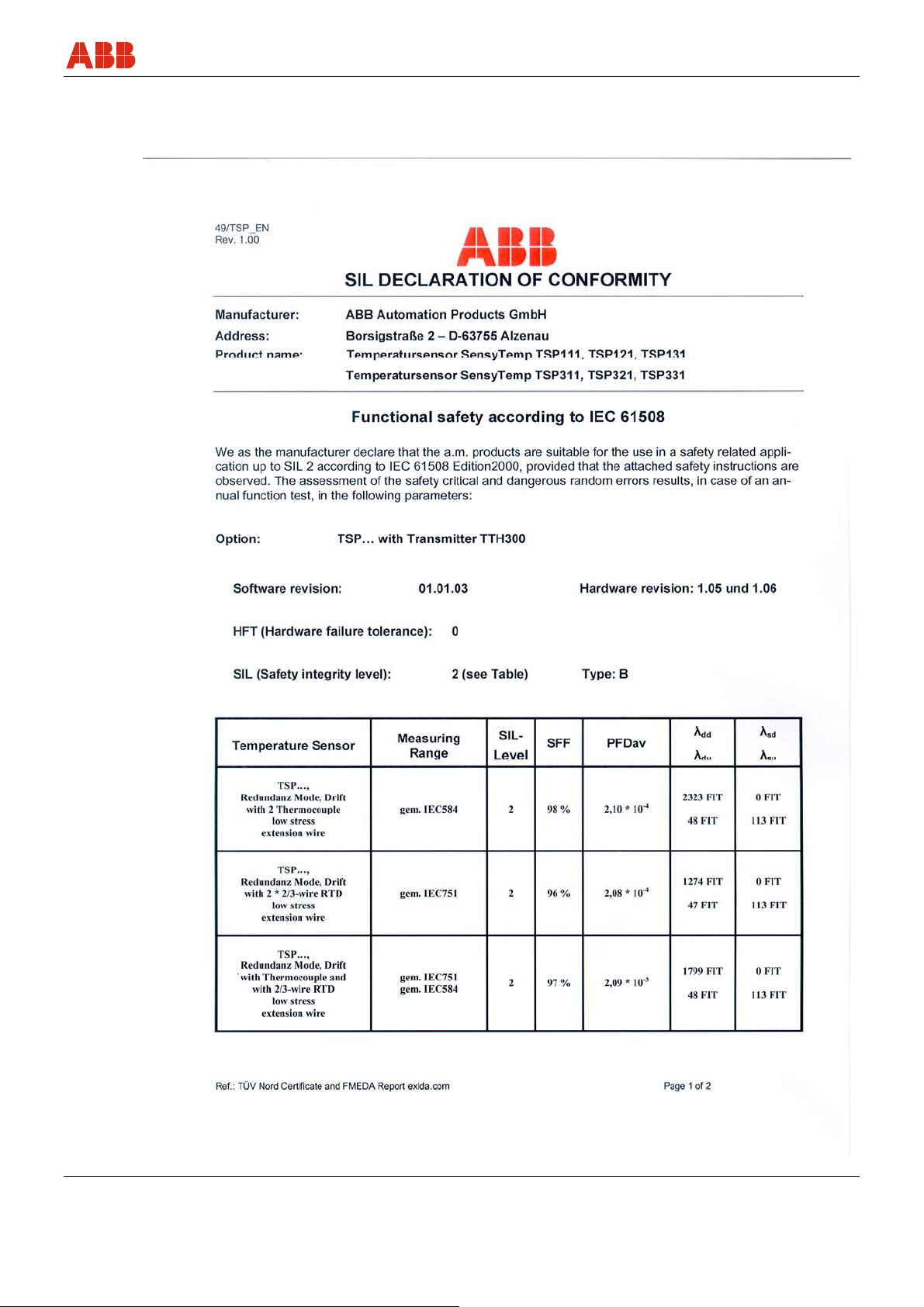
For the safety-relevant technical parameters, refer to the following SIL declaration of conformity.
SM/TSP/SIL-EN SensyTemp TSP 15
Page 16
Safety engineering parameters
16 SensyTemp TSP SM/TSP/SIL-EN
Page 17

Appendix
11 Appendix
Statement about the contamination of devices and components
The repair and/or maintenance of devices and components will only be performed when a completely filled out
explanation is present.
Otherwise, the shipment can be rejected. This explanation may only be filled out and signed by authorized
specialist personnel of the operator.
Customer details:
Company:
Address:
Contact person: Telephone:
Fax: E-Mail:
Device details:
Type: Serial no.:
Reason for the return/description of the defect:
Was this device used for working with substances which pose a threat or health risk?
F Yes F No
If yes, which type of contamination (please place an X next to the applicable items)
biological F corrosive/irritating F combustible (highly/extremely combustible) F
toxic F explosive F other toxic substances F
radioactive F
Which substances have had contact with the device?
1.
2.
3.
We hereby certify that the devices/parts shipped were cleaned and are free from any dangerous or poisonous
materials.
City, Date Signature and company stamp
SM/TSP/SIL-EN SensyTemp TSP 17
Page 18
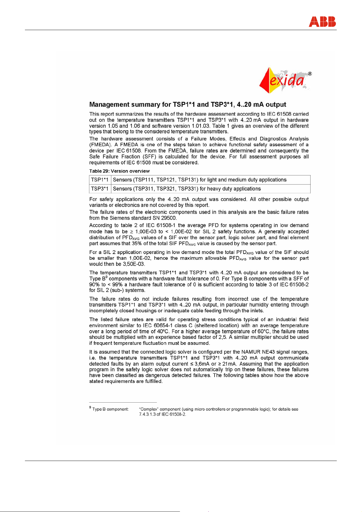
Management Summary FMEDA
12 Management Summary FMEDA
18 SensyTemp TSP SM/TSP/SIL-EN
Page 19
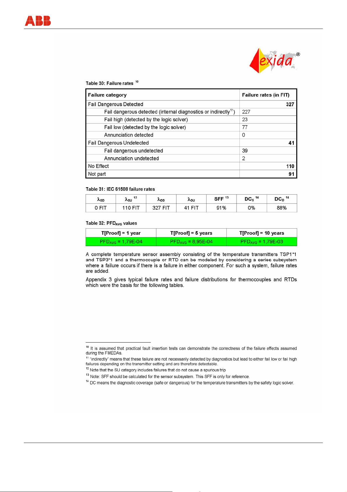
Management Summary FMEDA
SM/TSP/SIL-EN SensyTemp TSP 19
Page 20
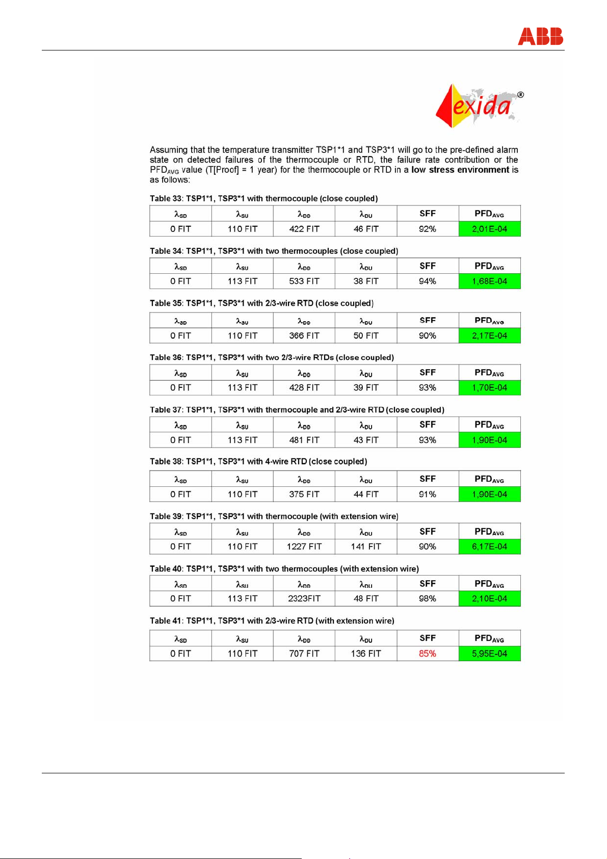
Management Summary FMEDA
20 SensyTemp TSP SM/TSP/SIL-EN
Page 21
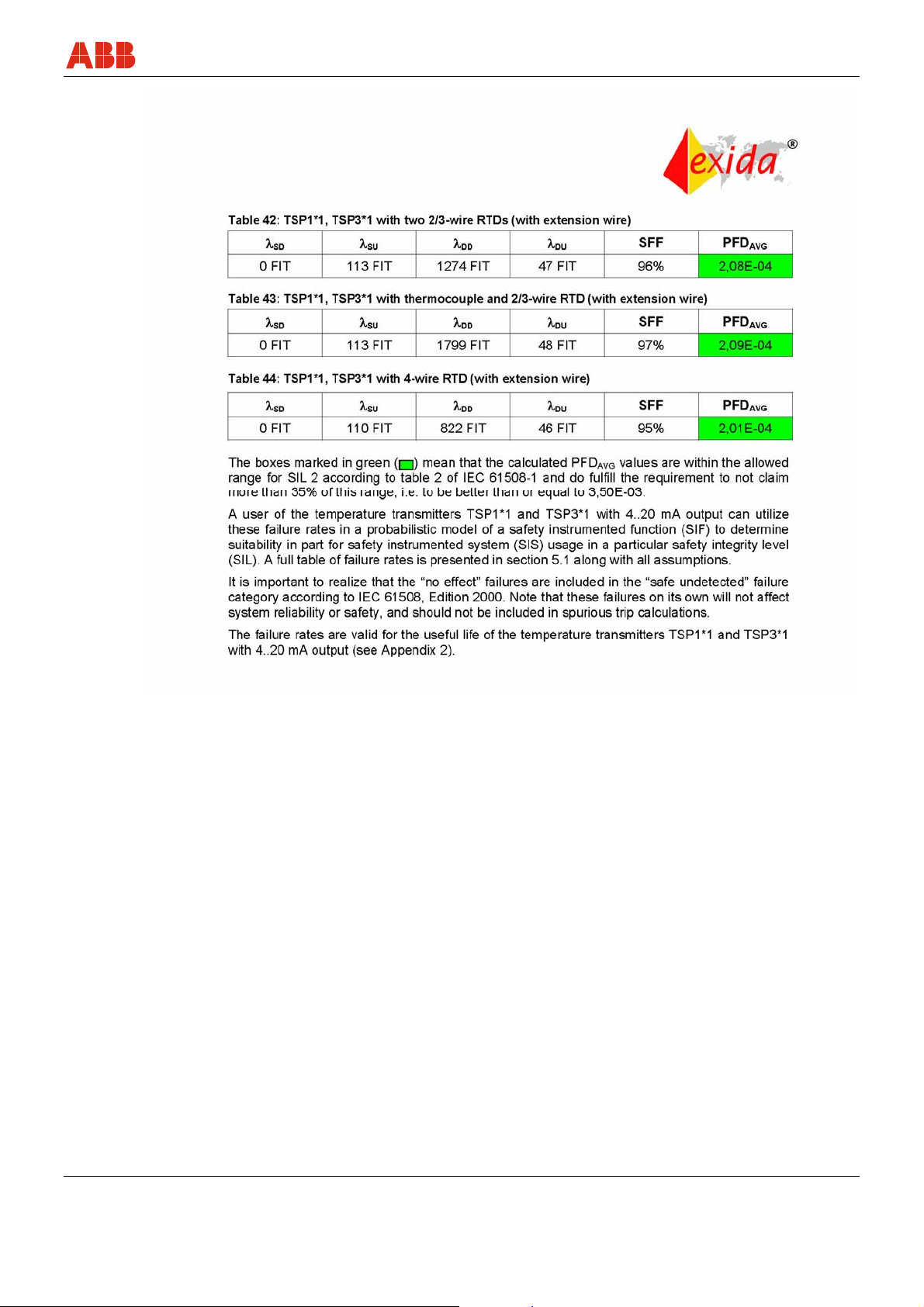
Management Summary FMEDA
SM/TSP/SIL-EN SensyTemp TSP 21
Page 22

ABB has Sales & Customer Support
expertise in over 100 countries worldwide.
www.abb.com/temperature
ABB Limited
Salterbeck Trading Estate
Workington, Cumbria
CA14 5DS
UK
Tel: +44 (0)1946 830 611
Fax: +44 (0)1946 832 661
ABB Inc.
125 E. County Line Road
Warminster, PA 18974
USA
Tel: +1 215 674 6000
Fax: +1 215 674 7183
The Company’s policy is one of continuous product
ABB Automation Products GmbH
Borsigstr. 2
63755 Alzenau
Germany
Tel: +49 551 905-534
Fax: +49 551 905-555
[email protected]
improvement and the right is reserved to modify the
information contained herein without notice.
Printed in the Fed. Rep. of Germany (05.2007)
© ABB 2007
3KXT161001R4801
SM/TSP/SIL-EN
 Loading...