

Page 1
Data sheet
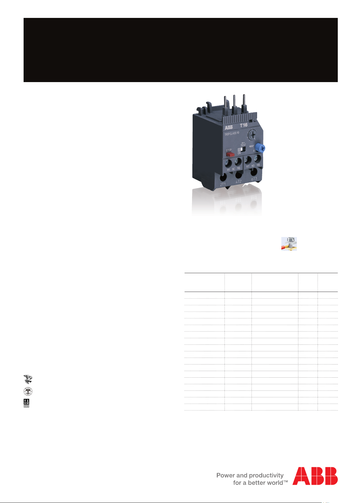
Thermal overload relay T16
Thermal overload relays are economic
electromechanical protection devices for
the main circuit. They are used mainly
to protect motors against overload and
phase failures. Starter combinations are
setup together with contactors.
2CDC231001S0010
Description
– Overload protection – trip class 10
– Phase loss sensitivity
– Temperature compensation from -25 … +60 °C
– Adjustable current setting for overload protection
– Automatic or manual reset selectable
– Suitable for three- and single-phase application
– Trip-free mechanism
– Status indication
– STOP and TEST function
– Direct mounting onto mini contactors or block contactors
Approvals
cULus UL 508
A
CB scheme
K
CCC
E
ABS
RINA
DNV
Lloyd’s Register
P
Marks
a
CE
Order data
T16 screw terminal
For B6/B7/VB6/VB7 mini contactors
For AS block contactors
Setting range AType Order code
0.10 ... 0.13 T16-0.13 1SAZ711201R1005 1 0.100
0.13 ... 0.17 T16-0.17 1SAZ711201R1008 1 0.100
0.17 ... 0.23 T16-0.23 1SAZ711201R1009 1 0.100
0.23 ... 0.31 T16-0.31 1SAZ711201R1013 1 0.100
0.31 ... 0.41 T16-0.41 1SAZ711201R1014 1 0.100
0.41 ... 0.55 T16-0.55 1SAZ711201R1017 1 0.100
0.55 ... 0.74 T16-0.74 1SAZ711201R1021 1 0.100
0.74 ... 1.00 T16-1.0 1SAZ711201R1023 1 0.100
1.00 ... 1.30 T16-1.3 1SAZ711201R1025 1 0.100
1.30 ... 1.70 T16-1.7 1SAZ711201R1028 1 0.100
1.70 ... 2.30 T16-2.3 1SAZ711201R1031 1 0.100
2.30 ... 3.10 T16-3.1 1SAZ711201R1033 1 0.100
3.10 ... 4.20 T16-4.2 1SAZ711201R1035 1 0.100
4.20 ... 5.70 T16-5.7 1SAZ711201R1038 1 0.100
5.70 ... 7.60 T16-7.6 1SAZ711201R1040 1 0.100
7.60 ... 10.0 T16-10 1SAZ711201R1043 1 0.104
10.0 ... 13.0 T16-13 1SAZ711201R1045 1 0.104
13.0 ... 16.0 T16-16 1SAZ711201R1047 1 0.104
Packing
unit
PCE
Weight
per PCE
kg
Suitable for mounting on:
AS09 … AS16
B6/BC6, B7/BC7
VB6/VBC6, VB7/VBC7
Page 2
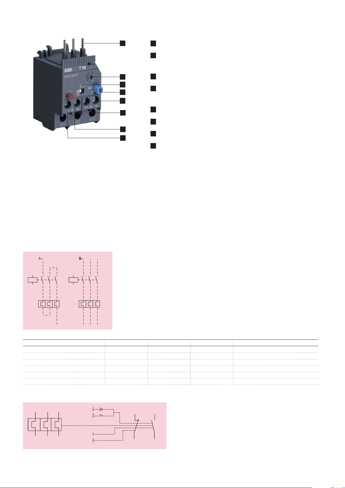
Functional description
3~1~
A
2CDC231001S0010
1
2
3
4
5
6
7
8
1
Terminals (1L1, 3L2, 5L3)
2
Current setting range
Adjustable current setting for overload protection
3
Status indication
4
RESET button
Automatic or manual reset selectable
5
Signaling contacts 97-98
6
Terminals 2T1, 4T2, 6T3
7
Tripping contacts 95-96
8
STOP button
Application / internal function
The thermal overload relays are three pole relays with bimetal tripping elements (1 per pole). The motor current flows through
the bimetal tripping elements and heats them directly and indirectly. In case of an overload (over current), the bimetal
elements become bent as a result of the heating. This leads to a release of the relay and a change of the contacts switching
position (95-96 / 97-98). The contact 95-96 is used to control the load contactor.
The overload relays have a setting scale in Amperes, which allows the direct adjusting of the relay without any additional
calculation. In compliance with international and national standards, the setting current is the rated current of the motor
and not the tripping current (no tripping at 1.05 x I, tripping at 1.2 x I; I = setting current). The relays are constructed in way
that they protect themselves in the event of an overload. The overload relay has to be protected against short-circuit. The
appropriate short-circuit protection devices are shown in the table.
Operation mode
2CDC232001F0010
Contact 95-96 Contact 97-98 Status indication Comment
Trip state open closed
RESET state closed open ON
TEST manual reset mode open closed
TEST auto reset mode open closed while TEST is operated
STOP while device is in trip state open closed STOP button has no function
STOP while device is in RESET state open open while STOP button is pressed
Wiring diagram
RESET
M
9795
2T1 4T2 6T3
2 - 2CDC106020D0201
TEST
STOP
9896
2CDC232001F0009
Page 3
Resistance and power loss per pole and short-circuit protection device
switching frequency
78
tripping time
(s)
9.1 0.36"8.6 0.34"
Type Setting range Resistance per
pole
lower value
A
upper value
A
Ω
Power loss Short-circuit
protection device
at lower value
W
at upper value Wcoordination
type 2
T16-0.13 0.10 0.13 106.51 1.1 2.0 0.5 A, Type T
T16-0.17 0.13 0.17 62.28 1.1 2.0 1.0 A, Type T
T16-0.23 0.17 0.23 37.43 1.1 2.0 1.0 A, Type T
T16-0.31 0.23 0.31 20.60 1.1 2.0 1.0 A, Type T
T16-0.41 0.31 0.41 11.42 1.1 2.0 2.0 A, Type gG
T16-0.55 0.41 0.55 6.35 1.1 2.0 2.0 A, Type gG
T16-0.74 0.55 0.74 3.62 1.1 2.0 4.0 A, Type gG
T16-1.0 0.74 1.00 1.920 1.1 2.0 6.0 A, Type gG
T16-1.3 1.00 1.30 1.065 1.1 2.0 6.0 A, Type gG
T16-1.7 1.30 1.70 0.623 1.1 2.0 10.0 A, Type gG
T16-2.3 1.70 2.30 0.340 1.1 2.0 10.0 A, Type gG
T16-3.1 2.30 3.10 0.187 1.1 2.0 10.0 A, Type gG
T16-4.2 3.10 4.20 0.102 1.1 2.0 20.0 A, Type gG
T16-5.7 4.20 5.70 0.059 1.1 2.0 20.0 A, Type gG
T16-7.6 5.70 7.60 0.031 1.1 2.0 35.0 A, Type gG
T16-10 7.60 10.00 0.0193 1.1 2.0 35.0 A, Type gG
T16-13 10.00 13.00 0.0131 1.3 2.2 40.0 A, Type gG
T16-16 13.00 16.00 0.0078 1.3 2.2 40.0 A, Type gG
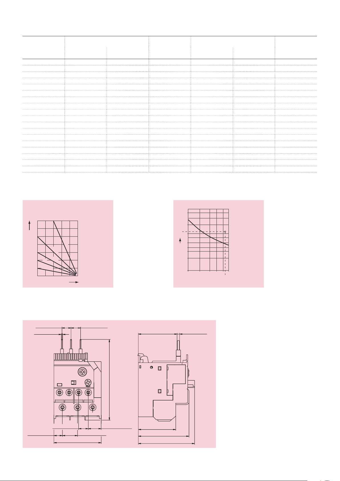
Technical diagrams
Intermittent periodic duty
(Op/h)
140
120
100
80
60
40
20
t = 1 s
a
t = 1.5 s
a
t = 3 s
a
t = 5 s
a
0
020406080100 (%)
duty ratio
Motor starting time
Dimensions
in mm and inches
1.2 0.05"
t = 0.5 s
a
ABB827833
40
20
11
10
6
4
3
2
1
3456
multiple of setting current
Tripping curve, starting from cold state
36.9 1.45" 2.4 0.09"
7.4
ABB836246
8.1 0.32" 14.4 0.57"
45 1.77"
76.7 3.02"
12.35 0.49"9.1 0.36"
35.6 1.4"
48.2 1.9"
53.5 2.11"
2CDC232008F0008
2CDC106020D0201 - 3
Page 4

Technical data IEC/EN
Data at TA = 40 °C and at rated values, if nothing else indicated
Main circuit
2T1-4T2-6T3
Rated operational voltage U
e
Setting range - thermal overload protection see table on page 1
Rated operational current AC-3 I
e
Trip class 10
Rated frequency 50/60 Hz
Number of poles 3
Resistance per pole see table on page 3
Power loss per pole see table on page 3
Short-circuit protection device see table on page 3
Isolation data 2T1-4T2-6T3
Rated impulse withstand voltage U
Rated insulation voltage U
imp
i
Pollution degree 3
Electrical connection 2T1-4T2-6T3
Connecting capacity solid 1/2 x 0.75 ... 1.5 mm²
stranded 1/2 x 1 ... 4 mm²
flexible with ferrule 1/2 x 0.75 ... 4 mm²
flexible with ferrule insulated 1/2 x 0.75 ... 4 mm²
flexible without ferrule 1/2 x 0.75 ... 4 mm²
Stripping length 12 mm
Tightening torque 1.1 ... 1.5 Nm
Connection screw M4 (Pozidrive 2)
690 V a.c.
- V d.c.
see
upper value of setting range, see table on page 3
6 kV
690 V
1/2 x 1.5 ... 4 mm²
4 - 2CDC106020D0201
Page 5

Auxiliary circuit
95-96, 97-98
Rated operational voltage U
Conventional free air thermal current I
e
th
NC, 95-96 6 A
NO, 97-98 4 A
Rated frequency d.c., 50/60 Hz
Number of poles 1NC + 1NO
Rated operational current Ie
acc. to IEC/EN 60947-5-1 for utilization category
at AC15 at 110-120 V NC, 95-96 3.00 A
NO, 97-98 0.75 A
at AC15 at 220-230-240 V NC, 95-96 3.00 A
NO, 97-98 0.75 A
at AC15 at 440 V NC, 95-96 0.75 A
NO, 97-98 0.75 A
at AC15 at 480-500 V NC, 95-96 0.75 A
NO, 97-98 0.75 A
at DC13 at 24 V NC, 95-96 1.25 A
NO, 97-98 1.25 A
at DC13 at 110-120-125 V NC, 95-96 0.55 A
NO, 97-98 0.55 A
at DC13 at 250 V NC, 95-96 0.27 A
NO, 97-98 0.27 A
at DC13 at 500 V NC, 95-96 0.15 A
NO, 97-98 0.15 A
Minimum switching capacity 17 V / 3 mA
Short-circuit protection device NC, 95-96 6 A, Type gG
NO, 97-98 4 A, Type gG
600 V
Isolation data 95-96, 97-98
Rated impulse withstand voltage U
Rated insulation voltage U
i
imp
6 kV
690 V
Pollution degree 3
Electrical connection 95-96, 97-98
Connecting capacity solid 1/2 x 0.75 ... 4 mm²
stranded 1/2 x 0.75 ... 4 mm²
flexible with ferrule 1/2 x 0.75 ... 2.5 mm²
flexible with ferrule insulated 1 x 0.75 ... 2.5 mm²
2 x 0.75 ... 1.5 mm²
flexible without ferrule 1/2 x 0.75 ... 1 mm²
1/2 x 1 ... 2.5 mm²
Stripping length 9 mm
Tightening torque 1 ... 1.5 Nm
Connection screw M3 (Pozidrive 2)
2CDC106020D0201 - 5
Page 6

General data
Duty time 100 %
Operating frequency without early tripping up to 15 operations/h or 60 operations/h with
40 % duty ratio, if the motor breaking current 6 x In
and the motor starting time does not exceed 1 s
Dimensions (W x H x D) see drawing "Dimensions" on page 3
Weight see table "Order data" on page 1
Mounting mount on the contactor and tighten the screws of
the main circuit terminals or with single mounting kit
on DIN rail (35 mm)
Mounting position position 1-5
Minimum distance to other units same type horizontal none
vertical not applicable
Minimum distance to electrical conductive board horizontal none
vertical on request
Degree of protection IP20
Altitude up to 2000 m
Electromagnetic compatibility
Electromagnetic compatibility not applicable
Environmental data
Ambient air temperature
Operation
Storage -50 ... +80 °C
Temperature compensation continuous
Vibration (sinusoidal) acc. to IEC/EN 60068-2-6 (Fc) 3g / 3 ... 150 Hz
Shock (half-sine) acc. to IEC/EN 60068-2-27 (Ea) 25g / 11 ms
open - compensated without derating
open
-25 ... +60 °C
-25 ... +60 °C
Standards / directives
Product standard IEC/EN 60947–4–1
IEC/EN 60497-5-1
IEC/EN 60947-1
UL 508, CSA 22.2 No. 14
Low Voltage Directive 2006/95/EC
EMC Directive 2004/108/EC
RoHS Directive 2002/95/EC
6 - 2CDC106020D0201
Page 7

Technical data UL/CSA
Full load amps and short-circuit protection device
Type Full load amps (FLA) Short-circuit protection device
480 / 600 V a.c. 480 / 600 V a.c.
SCCR Fuse type SCCR Fuse type
T16-0.13 0.13 A 18 kA 1 A, K5 100 kA 30 A, Class J
T16-0.17 0.17 A 18 kA 1 A, K5 100 kA 30 A, Class J
T16-0.23 0.23 A 18 kA 1 A, K5 100 kA 30 A, Class J
T16-0.31 0.31 A 18 kA 3 A, K5 100 kA 30 A, Class J
T16-0.41 0.41 A 18 kA 3 A, K5 100 kA 30 A, Class J
T16-0.55 0.55 A 18 kA 3 A, K5 100 kA 30 A, Class J
T16-0.74 0.74 A 18 kA 3 A, K5 100 kA 30 A, Class J
T16-1.0 1.00 A 18 kA 6 A, K5 100 kA 30 A, Class J
T16-1.3 1.30 A 18 kA 6 A, K5 100 kA 30 A, Class J
T16-1.7 1.70 A 18 kA 6 A, K5 100 kA 30 A, Class J
T16-2.3 2.30 A 18 kA 10 A, K5 100 kA 30 A, Class J
T16-3.1 3.10 A 18 kA 10 A, K5 100 kA 30 A, Class J
T16-4.2 4.20 A 18 kA 15 A, K5 100 kA 30 A, Class J
T16-5.7 5.70 A 18 kA 20 A, K5 100 kA 30 A, Class J
T16-7.6 7.60 A 18 kA 25 A, K5 100 kA 30 A, Class J
T16-10 10.0 A 18 kA 35 A, K5 100 kA 45 A, Class J
T16-13 13.0 A 18 kA 40 A, K5 100 kA 45 A, Class J
T16-16 16.0 A 18 kA 60 A, K5 100 kA 45 A, Class J
Main circuit
Max. operational voltage 600 V a.c.
Trip rating 125 % of FLA
Full load amps (FLA) see table above
Short-circuit rating RMS symmetrical see table above
Short-circuit protection device see table above
Electrical connection
Connecting capacity stranded 1/2 x AWG 18 ... 10
flexible without ferrule 1/2 x AWG 18 ... 10
Stripping length 12 mm
Tightening torque 9 ... 13 Ib-in
Auxiliary circuit
Conventional thermal current NC, 95-96 5 A
NO, 97-98 2.5 A
Making and breaking capacity NC, 95-96 B600, Q300
NO, 97-98 D300, Q300
Electrical connection
Connecting capacity stranded 1/2 x AWG 18 ... 12
flexible without ferrule 1/2 x AWG 18 ... 12
Stripping length 9 mm
Tightening torque 9 ... 13 Ib-in
2CDC106020D0201 - 7
 Loading...