

Page 1
2
0 20 40 60 80 100(%)
Closing time
0
20
40
60
80
100
120
140
Switching frequency
(ops/h)
ta = 0.5s
ta = 1s
ta = 1.5s
ta = 3s
ta = 3.5s
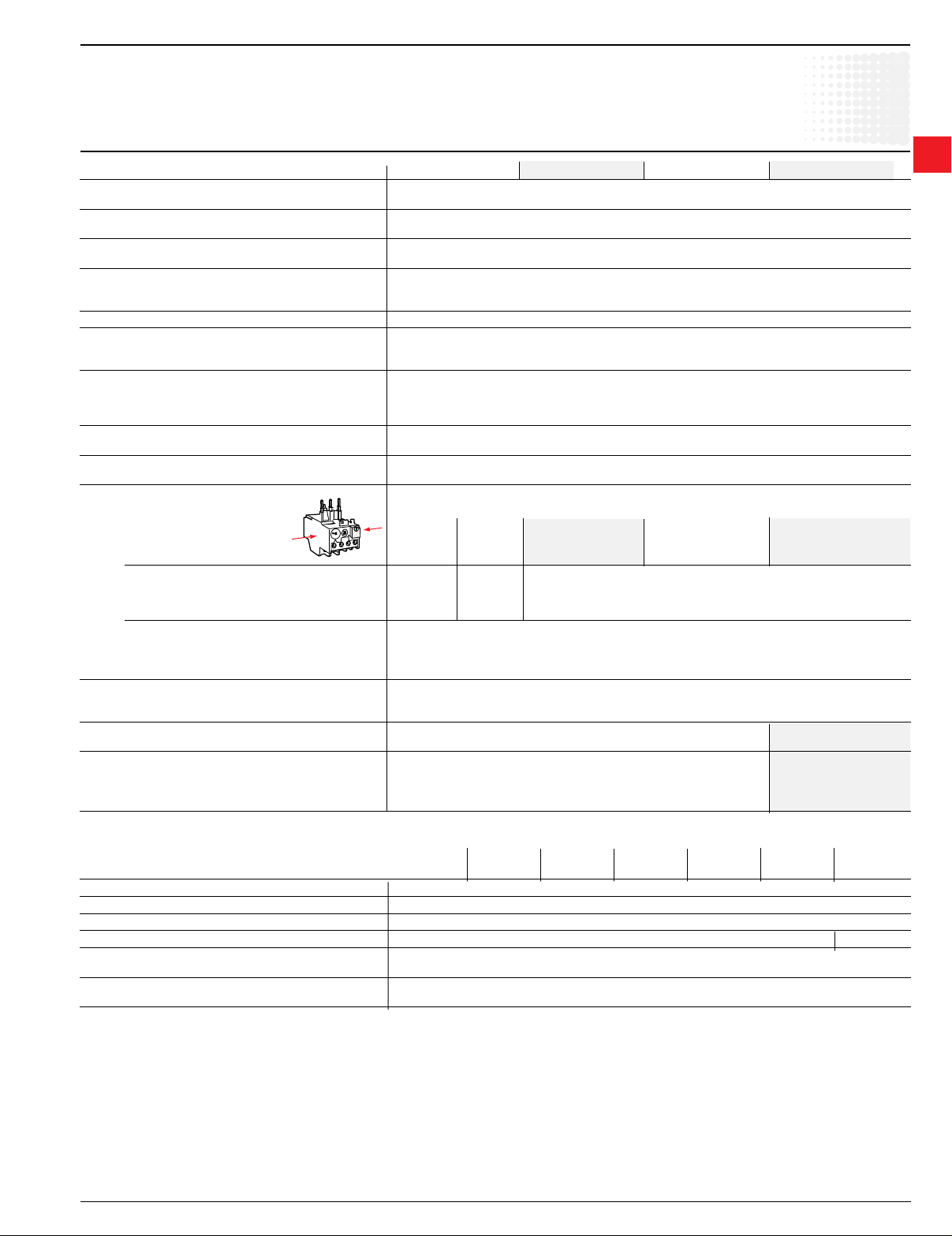
Intermittent duty
Ambient temperature
compensation limits
according to IEC 947-4-1
No tripping
Multiple of the setting current
Tripping
Ambient temperature
-20 -10 0 10 20 30 40 50
0.9
1.0
1.1
1.2
1.3
1.4
1.5
40
20
11
10
6
4
3
2
1
3 4 5
6 7
7.4
8
[s]
Multiple of the setting current
Tripping time
Thermal
Overload
relays
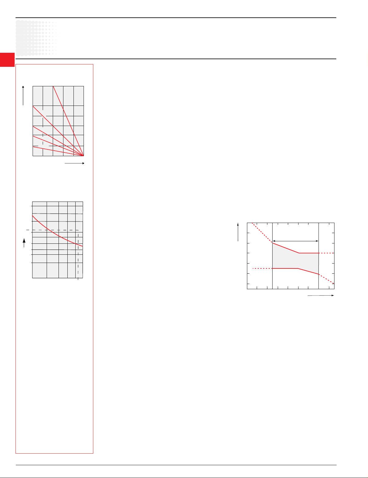
Switching frequency
in relation to load factor.
ta:
motor starting time.
Technical data
TA25DU – TA450DU
Switchingfrequency:
To avoid untimely tripping, TA and T thermal O/L relays have been designed to withstand roughly 15 switching operations
per hour with an approximately equal distribution between working and rest cycles.
In these conditions, the motor starting time must not exceed 1 second and the starting current must be lower than or equal
to 6 times the motor I
For intermittent operations, the diagram opposite species relay operating limits.
Example: Motor starting time: 1 sec.
Load factor: 40 %
Switching frequency: 60 ops./h according to diagram
For a higher number of operations and for load variations (e.g. frequent starting and braking), it is advisable to use
CUSTORAPID
For motors subject to particularly severe operating conditions (e.g. locked rotor) it is advisable to use protection combined
with a thermal O/L relay and the CUSTORAPID
Protection of motors with long starting time
See electronic overload relay section, pages 2.21 - 2.32.
Mounting position
On a support at an angle of ± 30° in relation to the vertical plane (standard position).
Other mounting positions possible, except mounting on a horizontal plane (in this case the tripping
mechanism would be located above the bimetals).
SpecialversionforEExemotors
Consult factory.
n
®
protection.
.
®
system.
Tripping limits at ambient temperatures varying by + 20°C
Ambient temperature compensation
Thermal O/L relays are compensated against ambient temperature
variations by a compensation bimetal which is sensitive to the
ambient temperature.
Thermal O/L relays are designed to operate between – 5 °C and
+40 °C in compliance with standard IEC 947-4-1. For a wider range
of –25° C to +55 °C consult the graph opposite.
Example:tripping at – 25 °C. Tripping takes place before 1.5 times
the setting current.
Resetting:TA25DU – TA450 DU thermal O/L relays have convertible
manual/automatic resetting.
Delivery:in manual resetting mode.
TA thermal O/L relay cold-state
tripping characteristics
2.10 Low Voltage Products & Systems
1SXU000023C0202 ABB Inc. • 888-385-1221 • www.abb.us/lowvoltage
Page 2
Technical data
A1
A2
TA25DU – TA80DU
Thermal
Overload
relays
Types TA25DU TA42DU TA75DU TA80DU
Standards:
(international, European)
Rated insulation voltage Ui V 690
according to IEC 947-4-1
Rated impulse withstand voltage U
according to IEC 947-4-1
Permissible ambient temperature
– for storage °C –40 to +70
– for operation °C –25 to +55 with temperature compensation (maximum values: see page 2.9)
Climatic withstand DIN 50017 Humidity in alternate climate KFW, 30 cycles
Mounting positions On a support at an angle of ±30° in relation to the vertical plane (standard position). Other positions
possible except mounting on a horizontal plane (in this case the tripping mechanism
would be located above the bimetals).
Shock withstand shock duration ms 15
at nominal Ie
Critical direction
of shocks A1, A2 multiples of g 12
Resistance to vibrations
(±1 mm, 50 Hz) multiples of g 8
Mounting – on contactor Latching below the contactor, screw xing on main terminals
– separate with DB - kit Using screws: 2 x M4 or 35 mm EN 50022
Terminals and cross-sectional areas TA25DU setting ranges:
for main conductors (motor side) from 0.1-0.16A 24-32 A
• screw terminal to 18-25A
– with cable clamp M4 –
– via tunnel connector – M5 M6 M6 M6
– at type for lug or bar – – – – –
• conductor cross-sectional area
– rigid solid or rigid stranded mm2 2 x 1.5 - 6 1 x 10 1 x 2.5 - 35 or 2 x 2.5 x 16
– exible with cable end mm2 2 x 1.5 - 4 2 x 0.75- 6 1 x 2.5 - 25 or 2 x 2.5 x 10
– recommended bars mm – – – – –
Terminals and cross-sectional area
for auxiliary conductors
• screw terminal (screw size)
– with cable clamp M 3.5
• conductor cross-sectional area
– rigid solid or rigid stranded 2 x mm2 0.75 - 4
– exible with cable end 2 x mm2 0.75 - 2.5
Degree of protection All the terminals are protected against direct contact according to All the terminals are
VDE 0106/Part. 100. (without additional terminal shrouds) protected against direct
direct contact according to
VDE0106/part 100 (with
additional terminal shrouds
for the main terminals
kV 6
imp
IEC 947-4-1, EN 60947-4-1
2
Pole Technical Characteristics
Types TA25 TA42 TA75 TA80 TA10 TA200 TA450
DU DU DU DU DU DU DU
Number of poles 3
Setting ranges see page 2.6
Tripping class according to IEC 947-4-1, EN 60947-1 10 A
Rated operational frequencies Hz 0 - 400 50/60
Max. switching frequency Up to 15 starts/h or 60 starts/h with 40 % on-load factor when neither
without untimely tripping the starting current of 6 x In nor the starting time 1 s are exceeded.
Resistance per phase in mΩ
and heat dissipation in W see page 2.13
Low Voltage Products & Systems 2.11
ABB Inc. • 888-385-1221 • www.abb.us/lowvoltage 1SXU000023C0202
Page 3

Technical data
A1
A2
Thermal
Overload
relays
2
Types TA110DU TA200DU TA450DU
Standards:
(international, European)
Rated insulation voltage Ui V 690 1000
according to IEC 947-4-1
Rated impulse withstand voltage U
according to IEC 947-4-1
Permissible ambient temperature
– for storage °C –40 to +70
– for operation °C –25 to +55 with temperature compensation (maximum values: see page 2.9)
Climatic withstand DIN 50017 Humidity in alternate climate KFW, 30 cycles
Mounting positions On a support at an angle of ±30° in relation to the vertical plane (standard position). Other positions
possible except mounting on a horizontal plane (in this case the tripping mechanism would
be located above the bimetals).
Shock withstand shock duration ms 15
at nominal Ie
Critical direction
of shocks A1, A2 multiples of g 12
Resistance to vibrations
(±1 mm, 50 Hz) multiples of g 8
Mounting – on contactor
– separate with DB - kit
Terminals and cross-sectional areas
for main conductors (motor side)
• screw terminal
– with cable clamp – – –
– via tunnel connector HC, M8 – –
– at type for lug or bar – M10 M10
• conductor cross-sectional area
– rigid solid or rigid stranded
– exible with cable end
– recommended bars
Terminals and cross-sectional area
for auxiliary conductors
• screw terminal (screw size)
– with cable clamp M 3.5
• conductor cross-sectional area
– rigid solid or rigid stranded 2 x
– exible with cable end 2 x
Degree of protection All the terminals are protected against direct contact according to
VDE 0106/Part. 100. (with additional terminal shrouds)
TA110DU – TA450DU
IEC 947-4-1, EN 60947-4-1
kV 6 8
imp
4 x M5 screws
2
mm
16 – 35 25 – 120 2 x 240
2
mm
16 – 35 25 – 95 2 x 240
mm 12 x 3 20 x 4 20 x 4...5
2
mm
0.75 - 4
2
mm
0.75 - 2.5
TechnicalcharacteristicsofauxiliarycontactsforthermalO/Lrelays:TA25DU to TA450DU
Auxiliary contacts normally closed N.C. normally open N.O.
Terminal marking 95-96 97-98
Rated operational voltage Ue VAC 500 500
Conventional thermal current (in free air) Ith A 10 6
Rated operational current Ie, AC-15
up to 240 V A 3.0 1.5
up to 440 V A 1.9 0.95
up to 500 V A 1.0 0.75
Rated operational current I
up to 250 V A 0.12 0.04
Protection against short circuits
gG (gl) fuses (according to IEC 269) A 10 6
S 271/S 281circuit-breaker A k3 k1
Maximum potential difference VAC 500 500
between N.C. and N.O. auxiliary contacts VDC 440 440
2.12 Low Voltage Products & Systems
1SXU000023C0202 ABB Inc. • 888-385-1221 • www.abb.us/lowvoltage
DC-13
e
Page 4
Technical data
M3~M3~M3~M
3~
SPEM
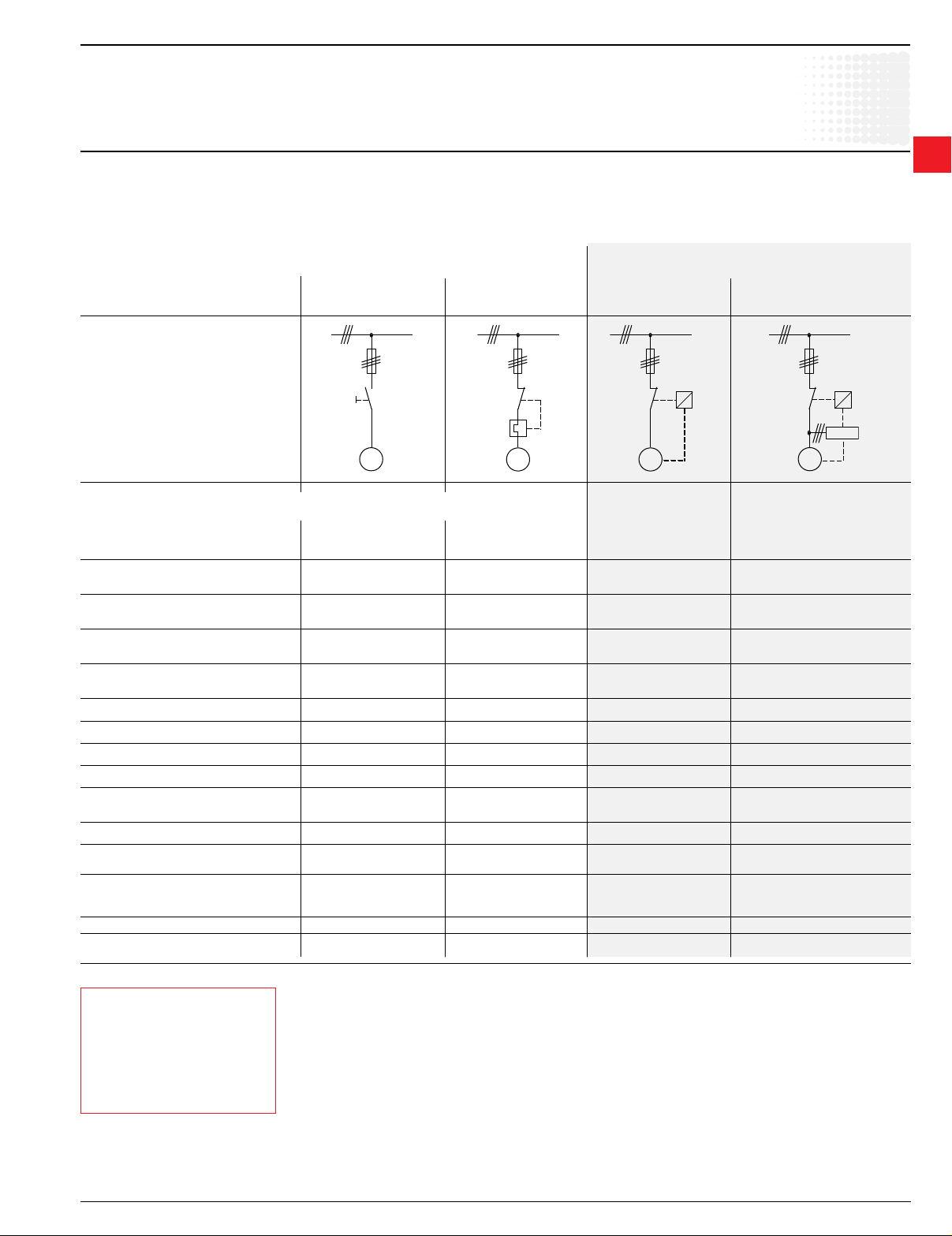
Motor protection; Choice of protective device
Motor Protection — general
It is very important to choose an adequate protective device for the safety of the motor during operation and for its durability.
The efciency of protection methods varies according to the application. The overview below will help you to choose.
There is no general rule and we are available to advise you for special applications and especially in the case of difcult starting.
Protective devices and efficiency
Protectioninrelationtocurrent: Protectioninrelationtotemperature:
Thermal
Overload
relays
2
Fuses Protective relay with Motor protection Motor protection
phase fault protection via CUSTORAPID
thermistor
®
via SPEM electronic
relay
Causes of dangerous overloads for the motor windings
1 Overload with current ❑ ● ● ●
1.2 times the nominal current
2 S1-S8 nominal duties ❑ ■ ● ●
according to IEC 34-I
3 Operation with starting, ❑ ■ ● ●
braking, reversal in operating direction
4 Operation with starting ❑ ■ ● ●
rate at > 15 cycles/hour
5 Locked rotor ■ ● ■ for motors with ●
special rotor
6 Overloads due to phase failure ❑ ● ● ●
7 Network undervoltage or overvoltage ❑ ● ● ●
8 Fluctuation of network frequency ❑ ● ●❑
9 Ambient temperature too high ❑ ● ●❑
10 Overheating due to external ❑ ❑ ●❑
cause (i.e. overheating of bearings)
11 Motor cooling disturbed ❑ ❑ ●❑
12 Undercurrent protection
on drop in load
13 Protection of asymmetry:
wrong phase direction
rotation or asymmetrical load
14 Earth fault protection
15 Automatic disconnection for
auxiliary load fault
Protectionefciency:
❑ unsuitable
■ very average efciency
● perfectly efcient
Low Voltage Products & Systems 2.13
ABB Inc. • 888-385-1221 • www.abb.us/lowvoltage 1SXU000023C0202
Note:Fuses
Fuses do not protect motors against overloads. They are only used to protect installations and lines against short circuits.
To ensure efcient protection of a motor against short circuits, it is advisable to use aM type fuses in association with thermal
OLR relays.
For the selection of fuses or circuit-breakers, refer to the indications given in this catalogue concerning contactors on the one
hand and thermal O/L relays on the other.
In general, fuse protection for direct-on-line starting must be sized as follows:
– aM fuses: choose the fuse rating immediately above the full load value of the motor current.
– gG (gI) fuses: determine the fuse rating immediately above the motor current value and choose the next highest fuse rating.
Page 5

Technical data
Thermal
Overload
relays
2
Resistance and Joule losses per phase, short circuit protection
Resistance and Joule losses per phase
Short circuit protection
Joule losses
Setting range Resistance per phase at
current per phase max. setting
from – to
A A mΩ W
TA25DU
0.1 – 0.16 85850 2.2
0.16 – 0.25 85150 2.2
0.25 – 0.4 13750 2.2
0.4 – 0.63 5370 2.2
0.63 – 1.0 2190 2.2
1.0 – 1.4 1120 2.2
1.3 – 1.8 670 2.2
1.7 – 2.4 383 2.2
2.2 – 3.1 229 2.2
2.8 – 4.0 137 2.2
3.5 – 5.0 87.5 2.2
4.5 – 6.5 61 2.2
6.0 – 8.5 30.4 2.2
7.5 – 11 18.2 2.2
10 – 14 11.2 2.2
13 – 19 6.3 2.3
18 – 25 4.7 2.9
24 – 32 3.2 3.3
TA42DU
18 – 25 5.5 3.43
22 – 32 2.89 2.91
29 – 42 1.84 3.24
TA75DU
18 – 25 5.5 3.43
22 – 32 2.89 2.91
29 – 42 1.84 3.24
36 – 52 1.3 3.51
45 – 63 0.936 3.72
60 – 80 0.615 3.94
TA80DU
29 – 42 1.84 3.24
36 – 52 1.3 3.51
45 – 63 0.936 3.72
60 – 80 0.615 3.94
Joule losses
Setting range Resistance per phase at
current per phase max. setting
from – to
A A mΩ W
TA110DU
80 – 110 0.378 3.78
TA200DU
100 – 135 0.318 5.79
110 – 150 0.255 5.74
130 – 175 0.214 6.55
150 – 200 0.182 7.28
TA450DU
130 – 185 — 2.5
165 – 235 — 2.5
220 – 310 — 2.5
2.14 Low Voltage Products & Systems
1SXU000023C0202 ABB Inc. • 888-385-1221 • www.abb.us/lowvoltage
Page 6

Tripping time
Minutes
Tripping current
in multiples of the setting current
Seconds
120
100
80
60
40
40
20
20
10
10
8
868
6
4
4
2
2
1
1
0.8 1 2 3 4 5 6 7 8 9 101.2 1.5
from warm state
from cold state
3 Phases
3 Phases
2 Phases
2 Phases
Tripping time
Minutes
Tripping current
in multiples of the setting current
Seconds
120
100
80
60
40
40
20
20
10
10
8
868
6
4
4
2
2
1
1
0.8 1 2 3 4 5 6 7 8 9 101.2 1.5
from warm state
from cold state
3 Phases
3 Phases
2 Phases
2 Phases
Tripping time
Minutes
Tripping current
in multiples of the setting current
Seconds
120
100
80
60
40
40
20
20
10
10
8
868
6
4
4
2
2
1
1
0.8 1 2 3 4 5 6 7 8 9 101.2 1.5
from warm state
from cold state
3 Phases
3 Phases
2 Phases
2 Phases
6
8
0.8 1 1.2 1.5 2 3 4 5 6 7 8 9 10
1
2
4
8
10
20
40
1
2
4
6
10
20
40
60
80
100
120
from warm state
from cold state
3 Phases
3 Phases
2 Phases
2 Phases
Tripping time
Minutes
Tripping current
in multiples of the setting current
Seconds
6
8
0.8 1 1.2 1.5 2 3 4 5 6 7 8 9 10
Tripping current
as multiple of setting current
1
2
4
8
10
20
40
1
2
4
6
10
20
40
60
80
100
120
Triping time
minutes
seconds
from warm state
from cold state
2 Phase
3 Phase
2 Phase
3 Phase
Technical data
Tripping curves
Overload
relays
TA25DU TA75DU TA110DU/SU TA450DU
TA-DU thermal O/L relays are 3-pole with manual or automatic resetting mode selection.
The resetting button can also be used for stopping.
Built-in auxiliary contacts are physically separate and, consequently, can be used in different circuits (control circuit/indication circuit).
Each relay is temperature compensated and ensures phase failure protection.
Protective relays up to size TA75DU are protected against direct contact via the front face. Terminal shrouds are available for TA200DU to TA450DU size relays.
The connecting terminals are delivered in open position with (+,-) pozidriv screws and screwdriver guidance. It is advisable to tighten unused terminal screws.
Thermal O/L relay tripping curves
TA25DU TA42DU, TA75DU and TA80DU TA110DU
(tripping class 10A) (tripping class 10A) (tripping class 10A)
Thermal
2
TA200DU TA450DU
(tripping class 10A) (tripping class 10A)
Low Voltage Products & Systems 2.15
ABB Inc. • 888-385-1221 • www.abb.us/lowvoltage 1SXU000023C0202
 Loading...