

ABB Terra AC Installation Manual

Installation manual
Terra AC
©
Copyright ABB. All rights reserved

Copyright
All rights to copyrights, registered trademarks, and trademarks reside with their respective
owners.
Copyright ® ABB EV Infrastructure. All rights reserved.
2
BCM.V3Y01.0-EN | 002

Contents
Contents
1 About this document.......................................................................... 7
1.1 Function of this document...................................................................................................... 7
1.2 Target group...............................................................................................................................7
1.3 Revision history..........................................................................................................................7
1.4 Language..................................................................................................................................... 7
1.5 Illustrations................................................................................................................................. 7
1.6 Units of measurement.............................................................................................................. 7
1.7 Typographical conventions......................................................................................................7
1.8 How to use this document.......................................................................................................7
1.9 General symbols and signal words........................................................................................ 8
1.10 Special symbols for warnings and dangers......................................................................... 9
1.11 Related documents................................................................................................................... 9
1.12 Manufacturer and contact data............................................................................................10
1.13 Abbreviations........................................................................................................................... 10
1.14 Terminology..............................................................................................................................10
1.15 Orientation agreements......................................................................................................... 11
2 Description......................................................................................... 12
2.1 Short description..................................................................................................................... 12
2.2 Intended use............................................................................................................................. 12
2.3 Product label (IEC portfolio)..................................................................................................12
2.4 Product label (UL portfolio)................................................................................................... 13
2.5 Working principle.....................................................................................................................14
2.6 Overview.................................................................................................................................... 15
2.6.1 Overview of the system..........................................................................................15
2.6.2 Overview of the EVSE, outside..............................................................................15
2.6.3 Overview of the EVSE, inside (CE model)........................................................... 17
2.6.4 Overview of the EVSE, inside (MID model).........................................................18
2.6.5 Overview of the EVSE, inside (UL model)........................................................... 19
2.6.6 Overview of the EVSE, inside (UL model with display)....................................20
2.7 Options...................................................................................................................................... 21
2.7.1 Display....................................................................................................................... 21
2.7.2 EV charge cable, Type 2.......................................................................................... 21
2.7.3 Socket, Type 2.......................................................................................................... 21
2.7.4 EV charge cable, Type 1 (UL portfolio)................................................................ 22
2.7.5 4G Communication................................................................................................. 22
2.7.6 Load management ................................................................................................. 22
2.8 Control elements..................................................................................................................... 23
2.8.1 LED indicators..........................................................................................................23
2.9 TerraConfig app to do the commissioning .......................................................................24
BCM.V3Y01.0-EN | 002 3

Contents
2.10 Description of the display screens (option)...................................................................... 24
2.10.1 Boot screen.............................................................................................................. 24
2.10.2 Standby/Idle screen............................................................................................... 25
2.10.3 Authorization screen.............................................................................................. 25
2.10.4 Preparing to charge screen...................................................................................26
2.10.5 Charging screen...................................................................................................... 26
2.10.6 Charging completed screen..................................................................................27
2.10.7 Fault detected display messages........................................................................ 27
3 Safety..................................................................................................29
3.1 Liability...................................................................................................................................... 29
3.2 Required qualifications for the installation engineer...................................................... 29
3.3 Personal protective equipment............................................................................................ 29
3.4 FCC compliance statement...................................................................................................30
3.5 Industry Canada compliance statement............................................................................ 30
3.6 General safety instructions....................................................................................................31
3.7 Signs on the EVSE.................................................................................................................... 31
3.8 Discard the EVSE or parts of the EVSE................................................................................32
3.9 Safety instructions for earthing........................................................................................... 32
3.10 Special safety instructions (IEC portfolio)......................................................................... 32
3.10.1 Safety instructions during installation............................................................... 32
3.11 Special safety instructions (UL portfolio).......................................................................... 33
3.11.1 Additional important safety instructions.......................................................... 33
4 Installation......................................................................................... 34
4.1 General installation procedure............................................................................................. 34
4.2 Unpack the EVSE......................................................................................................................34
5 Site preparation.................................................................................35
5.1 Select the site .......................................................................................................................... 35
5.2 Prepare the site (IEC portfolio).............................................................................................35
5.3 Prepare the site (UL portfolio)..............................................................................................35
6 Mechanical installation..................................................................... 37
6.1 General mechanical installation procedure........................................................................37
6.2 Prepare the holes for the mounting screws.......................................................................37
6.3 Install the upper mounting screws...................................................................................... 38
6.4 Install the EVSE on the wall....................................................................................................38
7 Electrical installation........................................................................ 39
7.1 General electrical installation procedure............................................................................39
7.2 Insert the AC input cable........................................................................................................39
4 BCM.V3Y01.0-EN | 002

Contents
7.3 Connect the AC input cable...................................................................................................40
7.3.1 Connect the AC input cable, 1 phase (IEC portfolio)....................................... 40
7.3.2 Connect the AC input cable, 3 phase (IEC portfolio)....................................... 40
7.3.3 Connect the AC input cable (UL portfolio)......................................................... 41
7.3.4 Secure the cables.................................................................................................... 41
7.4 Communication connections................................................................................................42
7.4.1 Insert the Ethernet cable.......................................................................................42
7.4.2 Connect the Ethernet cable.................................................................................. 42
7.4.3 Insert the wires for the smart meter communication.....................................43
7.4.4 Connect the wires for the smart meter communication................................ 43
7.4.5 Insert the Nano-M2M SIM card.............................................................................44
7.5 Replace the EV charge cable................................................................................................. 44
7.5.1 Replace the EV charge cable, 1 phase (IEC portfolio)...................................... 44
7.5.2 Replace the EV charge cable, 3 phase (IEC portfolio)......................................45
7.5.3 Replace the EV charge cable (UL portfolio)....................................................... 46
8 Commissioning..................................................................................48
8.1 General commissioning procedure..................................................................................... 48
8.2 Energize the EVSE................................................................................................................... 48
8.3 Set up the EVSE....................................................................................................................... 48
9 Access to parts.................................................................................. 50
9.1 Remove the cabinet cover..................................................................................................... 50
9.2 Install the cabinet cover.........................................................................................................50
9.3 Remove the maintenance cover............................................................................................51
9.3.1 Remove the maintenance cover (EVSE without display).................................51
9.3.2 Remove the maintenance cover ( EVSE with display)...................................... 51
9.4 Install the maintenance cover...............................................................................................52
9.4.1 Install the maintenance cover (EVSE without display).................................... 52
9.4.2 Install the maintenance cover (EVSE with display).......................................... 52
9.5 Remove the inner cover..........................................................................................................53
9.5.1 Remove the inner cover (EVSE without display................................................ 53
9.5.2 Remove the inner cover (EVSE with display)..................................................... 53
9.6 Install the inner cover............................................................................................................. 54
9.6.1 Install the inner cover (EVSE without display).................................................. 54
9.6.2 Install the inner cover (EVSE with display)........................................................ 54
10 Troubleshooting................................................................................ 55
10.1 Troubleshooting procedure.................................................................................................. 55
10.2 Troubleshooting table (IEC portfolio).................................................................................55
10.3 Troubleshooting table (UL portfolio)..................................................................................58
10.4 De-energize the EVSE..............................................................................................................61
BCM.V3Y01.0-EN | 002 5

Contents
11 Technical data....................................................................................62
11.1 EVSE Type..................................................................................................................................62
11.2 General specifications............................................................................................................63
11.3 Ambient conditions................................................................................................................ 64
11.4 Mass .......................................................................................................................................... 64
11.5 Protective device compliance............................................................................................... 65
11.5.1 Protective device compliance (IEC portfolio)....................................................65
11.5.2 Protective device compliance (UL portfolio).....................................................65
11.5.3 Protective device compliance (Singapore)........................................................ 66
11.6 Parts included in the delivery................................................................................................66
11.7 Required tools for installation..............................................................................................66
11.8 Requirements for the wall......................................................................................................67
11.9 Noise level................................................................................................................................. 67
11.10 Dimensions............................................................................................................................... 67
11.10.1 AC input with socket, cable Type 2......................................................................67
11.10.2 AC input with EV charge cable............................................................................. 68
11.10.3 Space requirements for installation................................................................... 69
11.11 AC input specifications.......................................................................................................... 69
11.11.1 General specifications........................................................................................... 69
11.11.2 400 VAC 3-phase with neutral (TT, TN) (IEC portfolio)................................... 70
11.11.3 230 VAC 1-phase (IEC portfolio)...........................................................................70
11.11.4 240 VAC (UL portfolio)........................................................................................... 70
11.11.5 AC input specifications (IEC portfolio)...............................................................70
11.11.6 AC input specifications (UL portfolio)................................................................ 71
11.12 General logic interface specifications................................................................................. 71
11.13 Cable specifications................................................................................................................ 71
11.13.1 AC input cable (IEC portfolio)............................................................................... 71
11.13.2 AC input cable (UL portfolio)................................................................................ 72
11.13.3 Ethernet cable specifications............................................................................... 72
11.13.4 RS485 cable specifications....................................................................................72
11.13.5 Dry contacts input...................................................................................................73
11.13.6 Dry contacts output................................................................................................73
11.13.7 EV charge cable specifications (IEC portfolio)................................................. 74
11.13.8 EV charge cable specifications (UL portfolio)...................................................74
11.14 AC output specifications....................................................................................................... 74
11.14.1 AC output specifications (IEC portfolio)............................................................74
11.14.2 AC output specifications (UL portfolio).............................................................74
11.15 Torque specifications............................................................................................................. 75
6 BCM.V3Y01.0-EN | 002

1 About this document
1.1 Function of this document
The document is only applicable for this EVSE (Terra AC), including the variants and
options listed in section 11.1. The EVSE from here on in the document is referred to
as the EVSE.
The document gives the information that is necessary to do these tasks:
• Installation
• Commissioning
1.2 Target group
The document is intended for qualified installation engineers.
For a description of the required qualifications, refer to section 3.2.
About this document
1.3 Revision history
Version
001 March 2020 Initial version
002 April 2021 Complete document over-
Date Description
1.4 Language
The original instructions of this document are in English (EN-US). All other language
versions are translations of the original instructions.
1.5 Illustrations
It is not always possible to show the configuration of your EVSE. The illustrations in
this document show a typical setup. They are for instruction and description only.
1.6 Units of measurement
SI units of measurement (metric system) are used. If necessary, the document
shows other units between parentheses () or in separate columns in tables.
haul
1.7 Typographical conventions
The lists and steps in procedures have numbers (123) or letters (abc) if the sequence
is important.
1.8 How to use this document
1. Make sure that you know the structure and contents of this document.
2. Read the safety chapter and make sure that you know all the instructions.
BCM.V3Y01.0-EN | 002 7
About this document
3. Do the steps in the procedures fully and in the correct sequence.
4. Keep the document in a safe location that you can easily access. This document
is a part of the EVSE.
1.9 General symbols and signal words
Signal word Description Symbol
Danger If you do not obey the instruction, this
can cause injury or death.
Warning If you do not obey the instruction, this
can cause injury.
Caution If you do not obey the instruction, this
can cause damage to the EVSE or to
property.
Note A note gives more data, to make it easier
to do the steps, for example.
- Information about the condition of the
EVSE before you start the procedure.
- Requirements for personnel for a procedure.
- General safety instructions for a procedure.
Refer to section
1.10.
Refer to section
1.10.
- Information about spare parts that are
necessary for a procedure.
- Information about support equipment
that is necessary for a procedure.
- Information about supplies (consumables) that are necessary for a procedure.
- Make sure that the power supply to the
EVSE is disconnected.
8 BCM.V3Y01.0-EN | 002
Signal word Description Symbol
- Electrotechnical expertise is required,
according to the local rules.
- Alternating current supply
Note: It is possible that not all symbols or signal words are present in
this document.
1.10 Special symbols for warnings and dangers
About this document
Symbol
Risk type
General risk
Hazardous voltage that gives risk of electrocution
Risk of pinching or crushing of body parts
Rotating parts that can cause a risk of entrapment
Note: It is possible that not all symbols are present in this document.
1.11 Related documents
Document name
Product data sheet All target groups
Installation manual Qualified installation engineer
User manual Owner
Declaration of conformity (CE) All target groups
You can find all related documents here: https://new.abb.com/ev-charging/terraac-wallbox.
BCM.V3Y01.0-EN | 002 9
Target group

About this document
1.12 Manufacturer and contact data
Manufacturer
ABB EV Infrastructure
George Hintzenweg 81
3068 AX, Rotterdam
The Netherlands
Contact data
ABB EV Infrastructure in your country can give you support on the EVSE. You can
find the contact data here: https://new.abb.com/ev-charging
1.13 Abbreviations
Abbreviation
AC Alternating current
CAN Controller area network
CPU Central processing unit
DC Direct current
EMC Electromagnetic compatibility
EV Electric vehicle
EVSE Electric vehicle supply equipment
MID Measuring Instruments Directive
NFC Near field communication
NoBo Notified body
OCPP Open charge point protocol
PE Protective earth
PPE Personal protective equipment
RFID Radio-frequency identification
Note: It is possible that not all abbreviations are present in this
document.
Definition
1.14 Terminology
Term
Network operating center
of the manufacturer
Cabinet Enclosure of the EVSE, including the components on
Contractor Third party that the owner or site operator hires to do
10 BCM.V3Y01.0-EN | 002
Definition
Facility of the manufacturer to do a remote check on
the correct operation of the EVSE
the inside
engineering, civil and electrical installation work
D
C
B
X
Z
Y
A
About this document
Term Definition
Grid provider Company that is responsible for the transport and dis-
tribution of electricity
Local rules All rules that apply to the EVSE during the entire lifecy-
cle of the EVSE. The local rules also include the national
laws and regulations.
Open charge point protocol
Owner Legal owner of the EVSE
Site operator Entity that is responsible for the day-to-day control of
User Owner of an EV, who uses the EVSE to charge the EV
Note: It is possible that not all terms are present in this document.
Open standard for communication with charge stations
the EVSE. The site operator does not have to be the
owner.
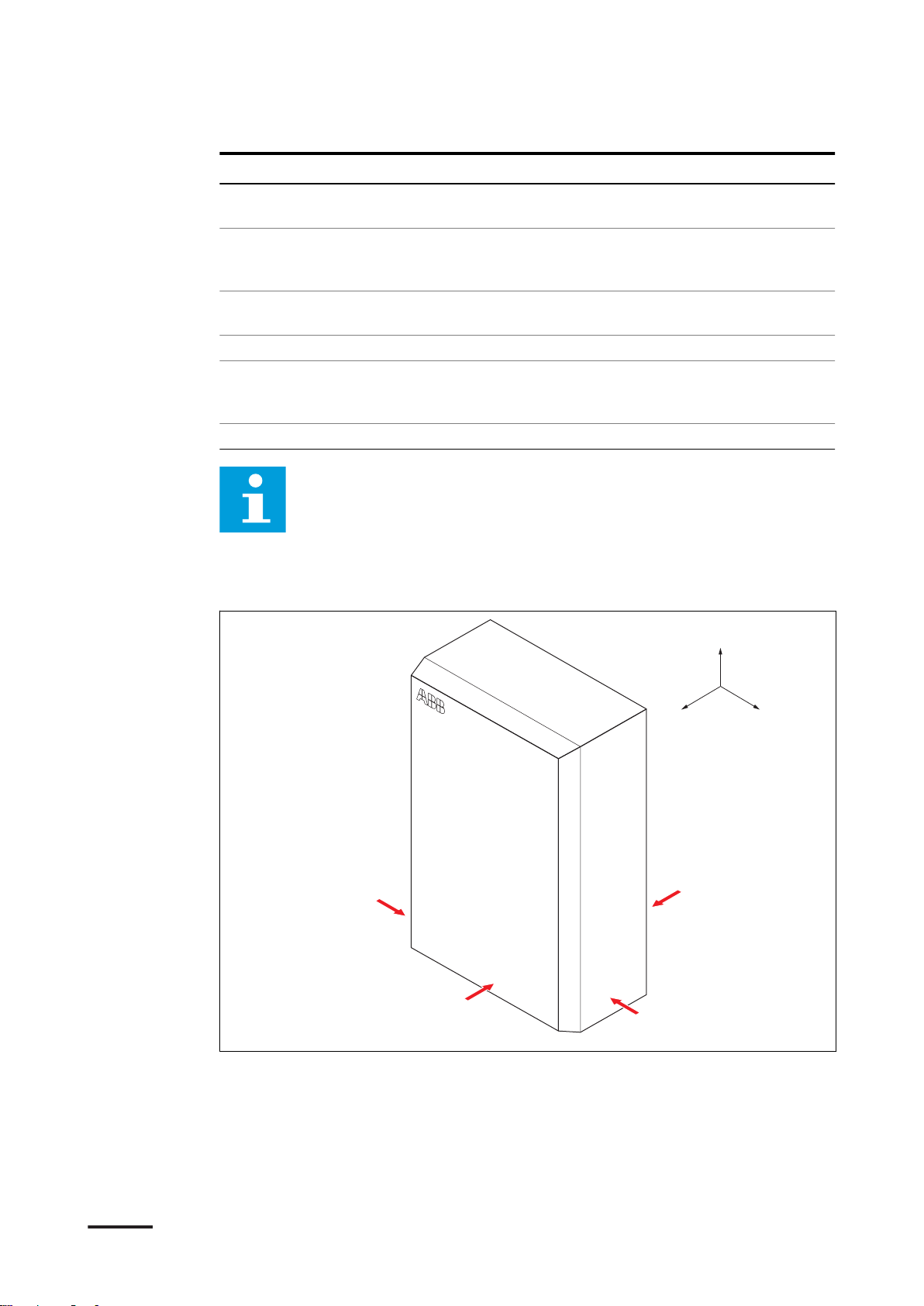
1.15 Orientation agreements
A Front side: face forward to the
EVSE during normal use
B Left side
C Right side
BCM.V3Y01.0-EN | 002 11
D Rear side
X X-direction (positive is to the right)
Y Y-direction (positive is rearward)
Z Z-direction (positive is upward)
XXX XXXX
TAC Wxx-[L]-WWYY-zxxxx
Cert. No. xxxx/xxxxxxx
Checksum: xxxxxxxx
FW Version xxxxxx
Active energie Cl. B (1)
0.25-5(32)A
Weight: 3.0kg
3x220/380...3x240/415V-
Terra AC W22-T-RD-M-0
1000imp/kWh
2020-39
-30ºC-55ºC
50Hz
XXXXXXXXXX
George Hintzenweg 81,
3068 AX, Rotterdam,
The Netherlands
IP54
Made in China www.abb.com
A
B
C
D
E
F
H
G
J
I
K
L
M
O
N
Description
2 Description
2.1 Short description
The EVSE (Terra AC) is an AC charging station that you can use to supply electricity
to an EV. The Terra AC offers tailor-made, intelligent and network charging
solutions for your company or home. The EVSE can connect to the internet via GSM,
WiFi or LAN.
2.2 Intended use
The EVSE is intended for the AC charging of EVs. The EVSE is intended for indoor or
outdoor use.
The technical data of the EVSE must comply with the properties of the electrical
grid, the ambient conditions and the EV. Refer to chapter 11.
Only use the EVSE with accessories that the manufacturer provides or that obey the
local rules.
The EVSE AC input is intended for a hardwired installation that complies with the
applicable national regulations.
Danger:
General risk
• If you use the EVSE in any other way than described in the related
documents, you can cause death, injury and damage to property.
• Use the EVSE only as intended.
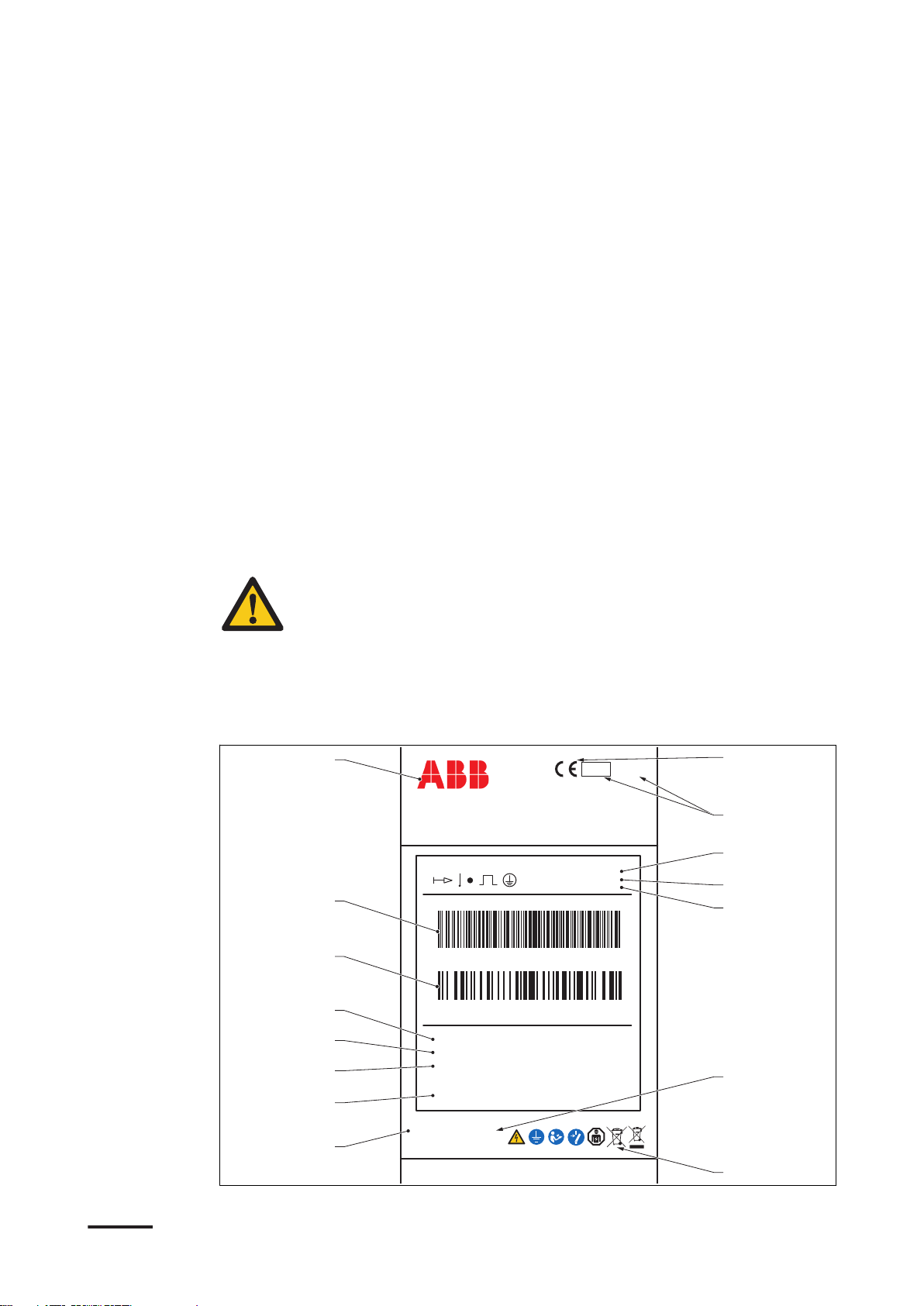
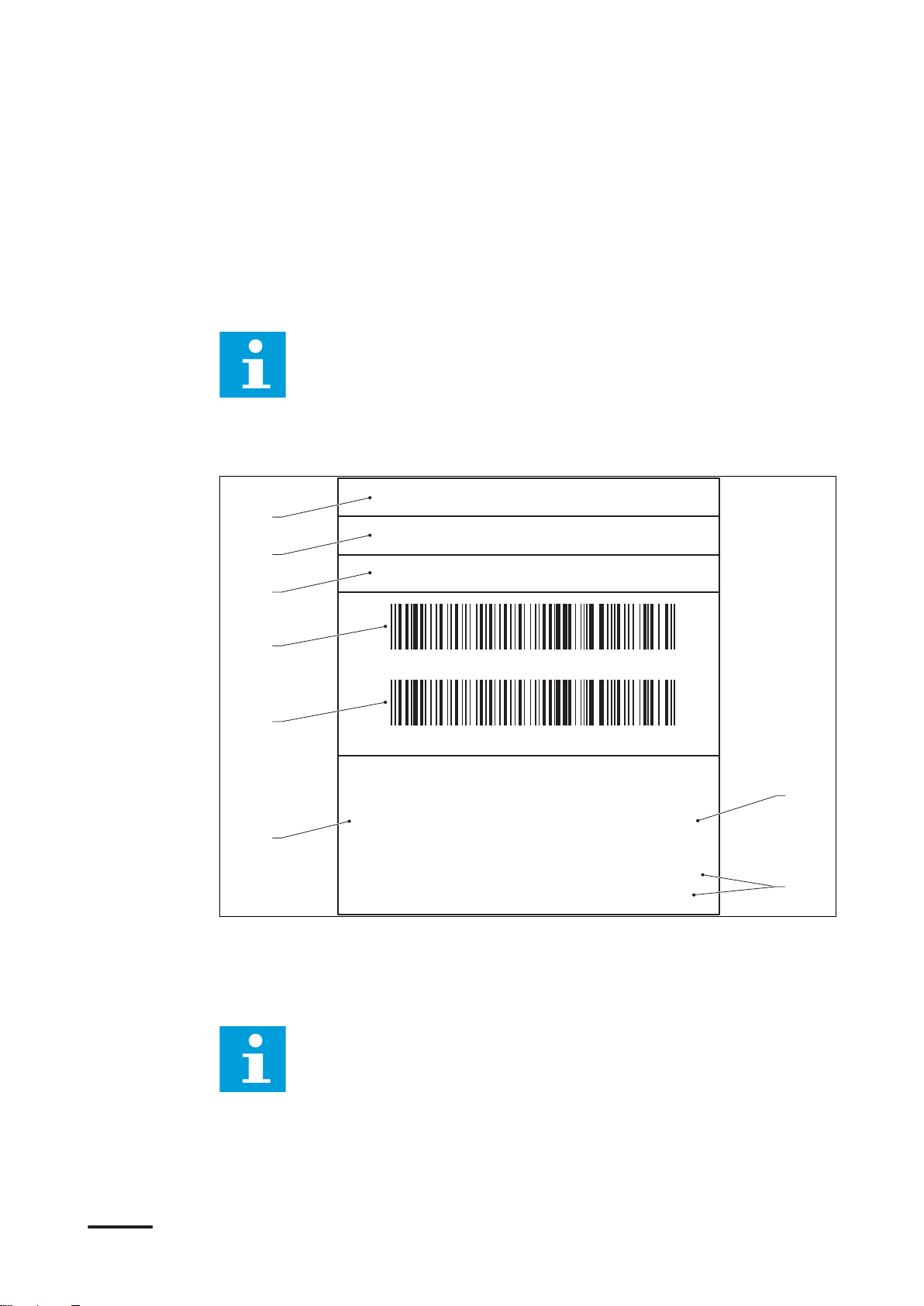
2.3 Product label (IEC portfolio)
12 BCM.V3Y01.0-EN | 002
SN: TACW7-[L]-WWYY-zxxxx
PN: XXXXXXXXXX
MODEL: Terra AC WX-P8-XX-XXX-X
TAC Wx-[L]-WWYY-zxxxx
XXXX XXXXXX
For use with electric vehicles
Pour utilisation avec des véhicules électriques
240V ~ / 60Hz 32A TYPE 3 -30ºC~50ºC
Ventilation Not Required Aucune ventilation requise
Raintight Étanche à la pluie Weight: 7.0kg
Dusttight Étanche à la poussière Poids: 7.0kg
A
B
C
D
E
F
G
H
Description
A Brand
B Barcode with the serial number
C Barcode with the part number of
the EVSE
D Product model number
E MID accuracy class
F EVSE rating
G Mass of the EVSE
H Address of the manufacturer
Note: The data in the illustration is only an example. Find the product
label on your EVSE to see the applicable data. Refer to section 2.6.2.
2.4 Product label (UL portfolio)
I CE mark
J MID mark and notified body
number
K MID certificate number
L MID software checksum
M MID FW version
N Ingress protection rating
O Reference to the manual
A Serial number
B Part number of the EVSE
C Product model number
D Barcode with the serial number of
the EVSE
Note: The data in the illustration is only an example. Find the product
label on your EVSE to see the applicable data. Refer to section 2.6.2.
E Barcode with the part number of
the EVSE
F Power rating of the EVSE
G Ambient temperature
H Mass of the EVSE
BCM.V3Y01.0-EN | 002 13
RFID
CPU
4G
IN OUT
A
H
I
B C D E F G
J
M
K L N
O
Q
P
11
* * * * *
3
4 4 4 4 4 4 4
2
3
2
* * **
**
*
*
*
Description
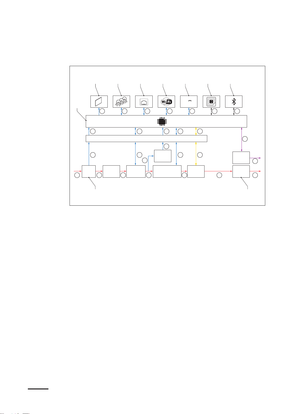
2.5 Working principle
A LEDs
B Ethernet
C WiFi
D 4G
E RFID
F Bluetooth
G CPU system
H Isolation
1. The user initiates a charge session request (black lines).
2. The EVSE verifies the status of the EV (purple lines).
3. The EVSE goes on and AC power goes to the EV (yellow lines).
4. The charge session starts. AC power flows from the power grid to the EV (red
lines).
5. The electrical interfaces of the EVSE communicate with the on-board computer
(blue lines).
(*): Connections between parts of the EVSE and the CPU system. The arrow shows
the direction of the input and output signals.
I AC/DC power supply
J AC input
K Surge protection
L Earth(ground) fault protection
M AC input metering
N AC isolation relay
O Control pilot
P AC output
14 BCM.V3Y01.0-EN | 002
2.6 Overview
E
A B
CD
G
F
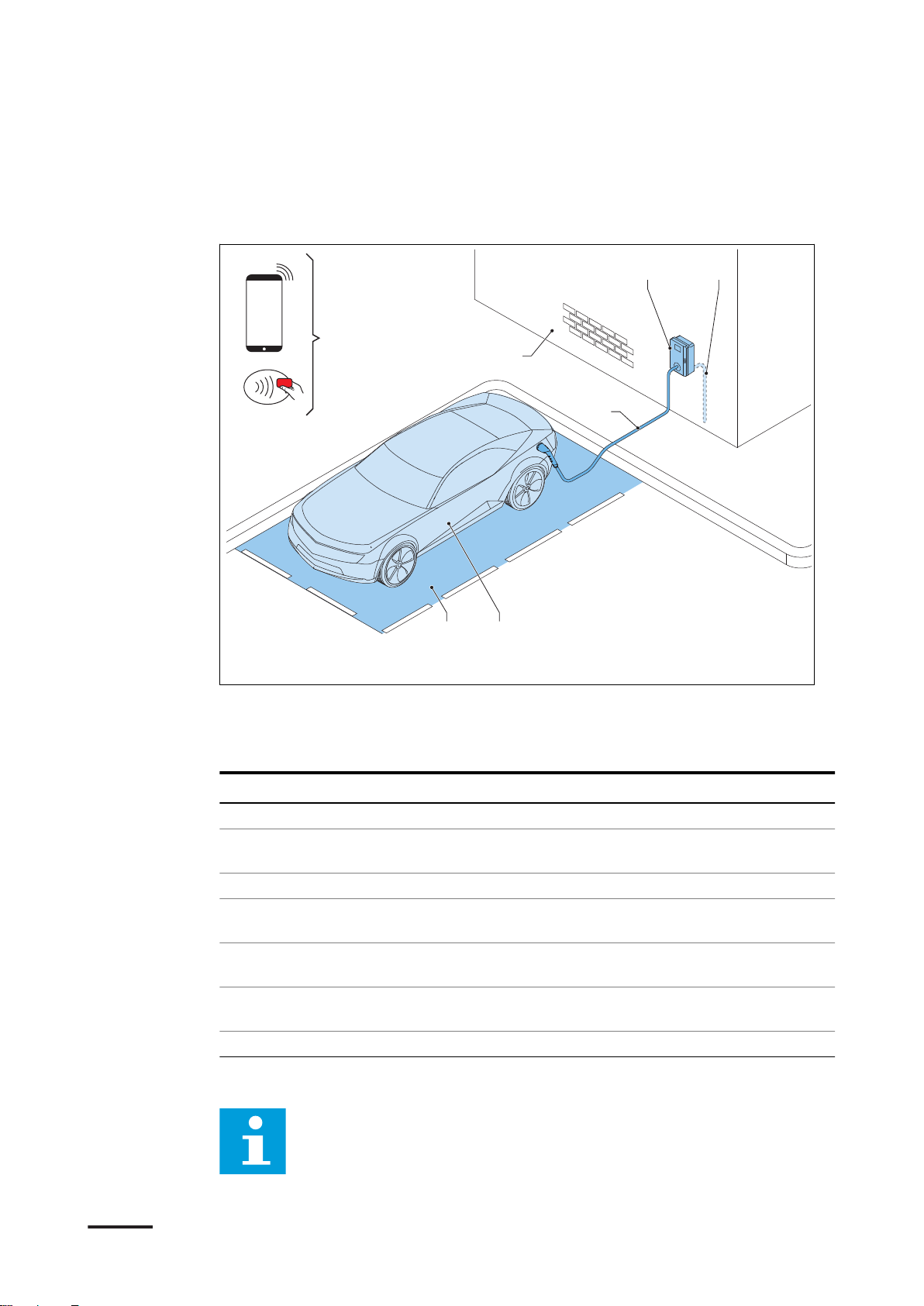
2.6.1 Overview of the system
Description
A EVSE
B AC grid input
C EV
D Parking space
Part Function
EVSE Refer to section 2.2.
Structure To install the EVSE on and to keep the
AC grid input To supply the electricity to the EVSE
EV charge cable To conduct the current from the EVSE to
EV The EV of which the batteries need to be
Parking space Location for the EV during the charge
RFID card or smartphone To authorize the user to use the EVSE
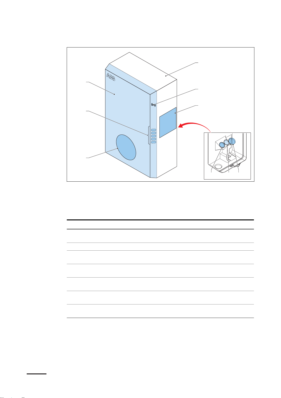
2.6.2 Overview of the EVSE, outside
The illustration shows the EVSE model without a display.
Note:
E RFID card or smartphone
F Structure to install the EVSE on
G EV charge cable
EVSE in position.
the EV
charged
session
BCM.V3Y01.0-EN | 002 15
A
F
E
H
I
G
B C D
Description
A Connection for the EV charge cable
B Openings for the smart meter
connections
C Opening for the Ethernet cable
D Opening for the AC input cable
E LED indicators
Part Function
Connection for the EV
charge cable
Openings Openings for the cables that go into the EVSE
LED indicators To show the status of the EVSE and the charge ses-
Cabinet cover To prevent a user to access the installation and main-
Enclosure To reduce the accessibillity of unqualified persons to
RFID reader To authorize the start or stop of a charging session
Product label To show the identification data of the EVSE. Refer to
To connect the EV charge cable
sion. Refer to section 2.8.1.
tenance parts of the EVSE
the inside of the EVSE
with an RFID card
section 2.3.
F Cabinet cover
G Enclosure
H RFID reader
I Product label
16 BCM.V3Y01.0-EN | 002

2.6.3 Overview of the EVSE, inside (CE model)
A B
C
E
D
F
G
Description
A Maintenance cover
B Primary Ethernet connection
C Socket for a Nano-M2M SIM card
D Smart meter connection
Part Function
Maintenance cover To prevent access to the electrical components of the
EVSE
Primary Ethernet connection
Socket for a Nano-M2M
SIM card
Smart meter connection To connect the cables for Modbus RTU - RS485
Terminal block for dry contacts input and output
Terminal block for the AC
input
Terminal block for the EV
charge cable
To connect the Ethernet cable
To connect the EVSE to the internet 4G
Not used
To connect the AC input cable from the grid
To connect the EV charge cable or the socket outlet
E Terminal block for dry contacts
input and output
F Terminal block for the AC input
G Terminal block for the EV charge
cable or the socket
BCM.V3Y01.0-EN | 002 17
A B C D
E
G
F
H
I
Description
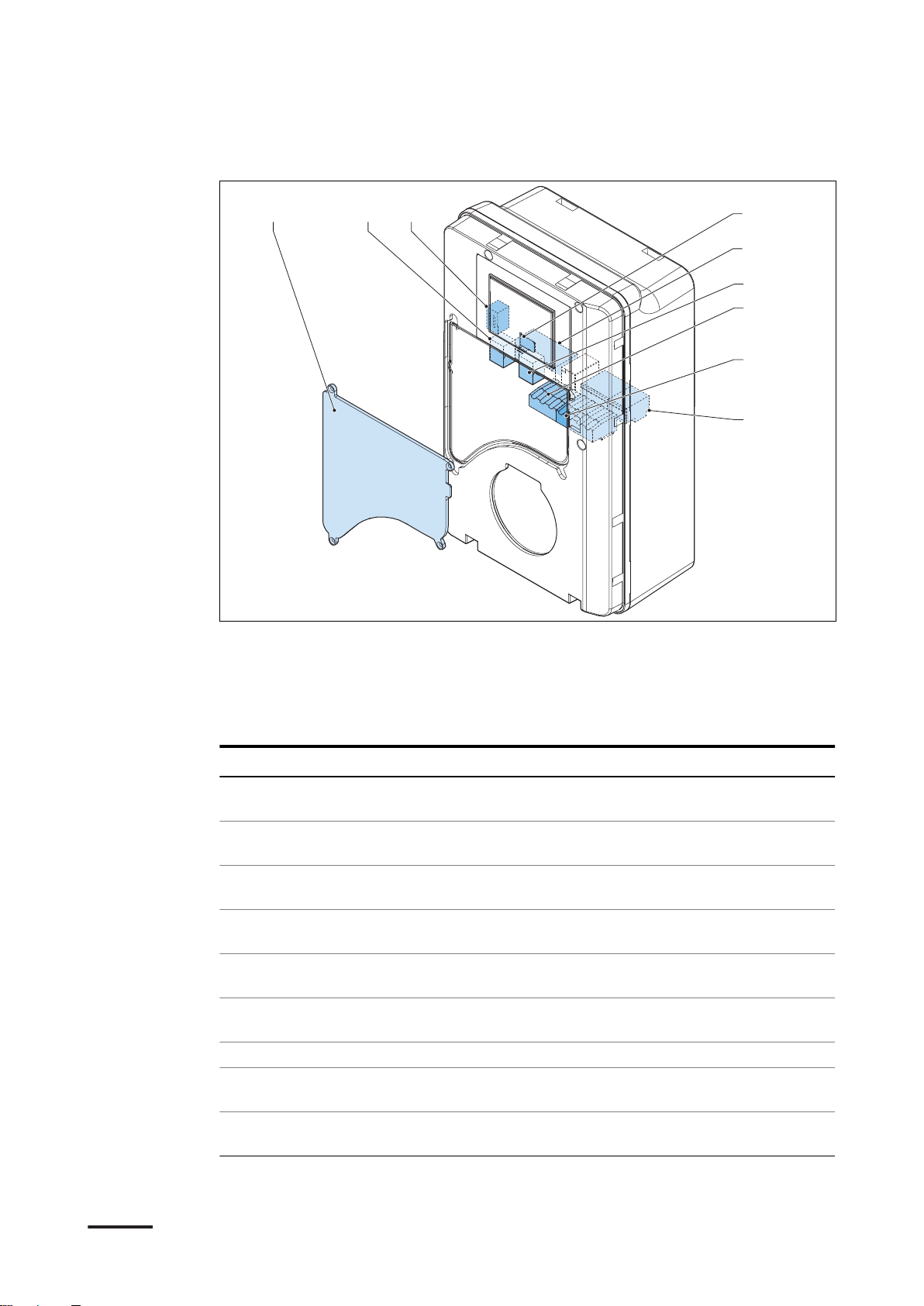
2.6.4 Overview of the EVSE, inside (MID model)
A Maintenance cover
B Primary Ethernet connection
C Electrical pulse connector
D Socket for a Nano-M2M SIM card
E Terminal block for the AC input
Part Function
Maintenance cover To prevent access to the electrical components of the
EVSE
Primary Ethernet connection
Electrical pulse connector Use for manufacturer only. Do not change or connect
Socket for a Nano-M2M
SIM card
Terminal block for the AC
input
Secondary Ethernet connection
Smart meter connection To connect the cables for Modbus RTU - RS485
Terminal block for dry contacts input and output
Terminal block for the EV
charge cable
To connect the Ethernet cable
cables to this input yourself.
To connect the EVSE to the internet 4G
To connect the AC input cable from the grid
To use one Ethernet cable connection for multiple EVSEs. There is no communication between the EVSEs.
Not used
To connect the EV charge cable or the socket outlet
F Secondary Ethernet connection
G Smart meter connection
H Terminal block for dry contacts
input and output
I Terminal block for the EV charge
cable or the socket
18 BCM.V3Y01.0-EN | 002
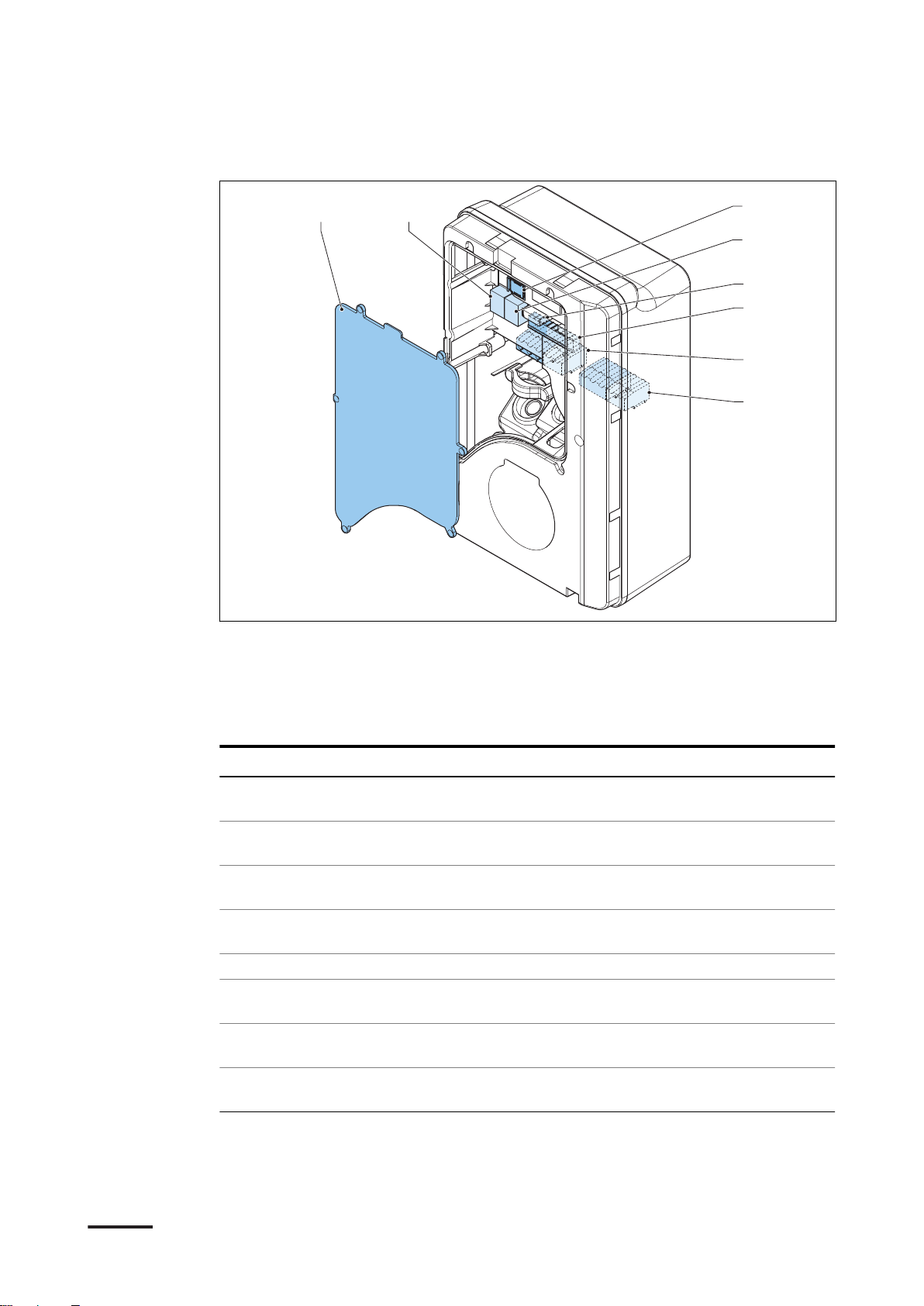
2.6.5 Overview of the EVSE, inside (UL model)
A B
C
D
F
E
G
H
Description
A Maintenance cover
B Primary Ethernet connection
C Socket for a Nano-M2M SIM card
D Secondary Ethernet connection
Part Function
Maintenance cover To prevent access to the electrical components of the
EVSE
Primary Ethernet connection
Socket for a Nano-M2M
SIM card
Secondary Ethernet connection
Smart meter connection To connect the cables for Modbus RTU - RS485
Terminal block for dry contacts input and output
Terminal block for the AC
input
Terminal block for the EV
charge cable or the socket
To connect the Ethernet cable
To connect the EVSE to the internet 4G
To use one Ethernet cable connection for multiple EVSEs. There is no communication between the EVSEs.
Not used
To connect the AC input cable from the grid
To connect the EV charge cable or the socket outlet
E Smart meter connection
F Terminal block for dry contacts
input and output
G Terminal block for the AC input
H Terminal block for the EV charge
cable or the socket
BCM.V3Y01.0-EN | 002 19
A B C
D
F
E
G
H
Description
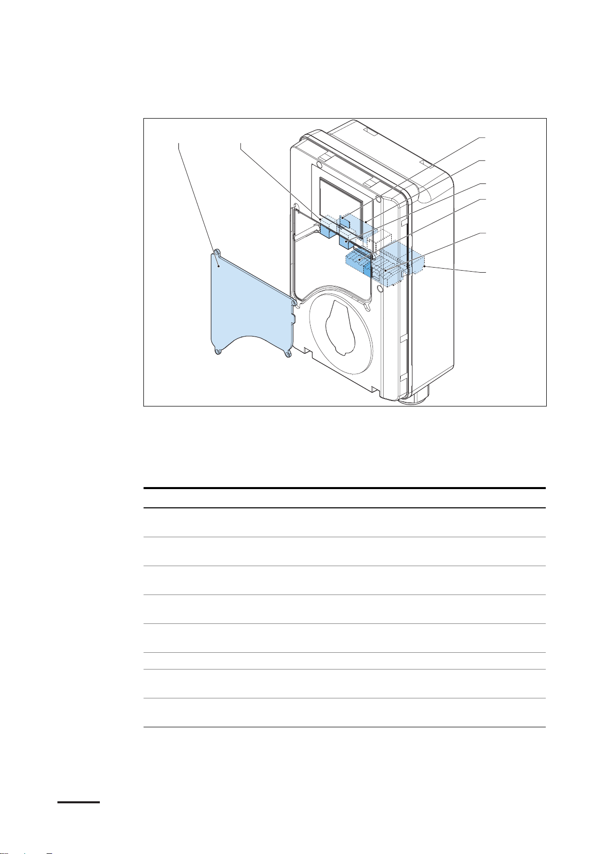
2.6.6 Overview of the EVSE, inside (UL model with display)
A Maintenance cover
B Primary Ethernet connection
C Socket for a Nano-M2M SIM card
D Terminal block for the AC input
Part Function
Maintenance cover To prevent access to the electrical components of the
EVSE
Primary Ethernet connection
Socket for a Nano-M2M
SIM card
Terminal block for the AC
input
Secondary Ethernet connection
Smart meter connection To connect the cables for Modbus RTU - RS485
Terminal block for dry contacts input and output
Terminal block for the EV
charge cable or the socket
To connect the Ethernet cable
To connect the EVSE to the internet 4G
To connect the AC input cable from the grid
To use one Ethernet cable connection for multiple EVSEs. There is no communication between the EVSEs.
Not used
To connect the EV charge cable or the socket outlet
E Secondary Ethernet connection
F Smart meter connection
G Terminal block for dry contacts
input and output
H Terminal block for the EV charge
cable or the socket
20 BCM.V3Y01.0-EN | 002
2.7 Options
A
A
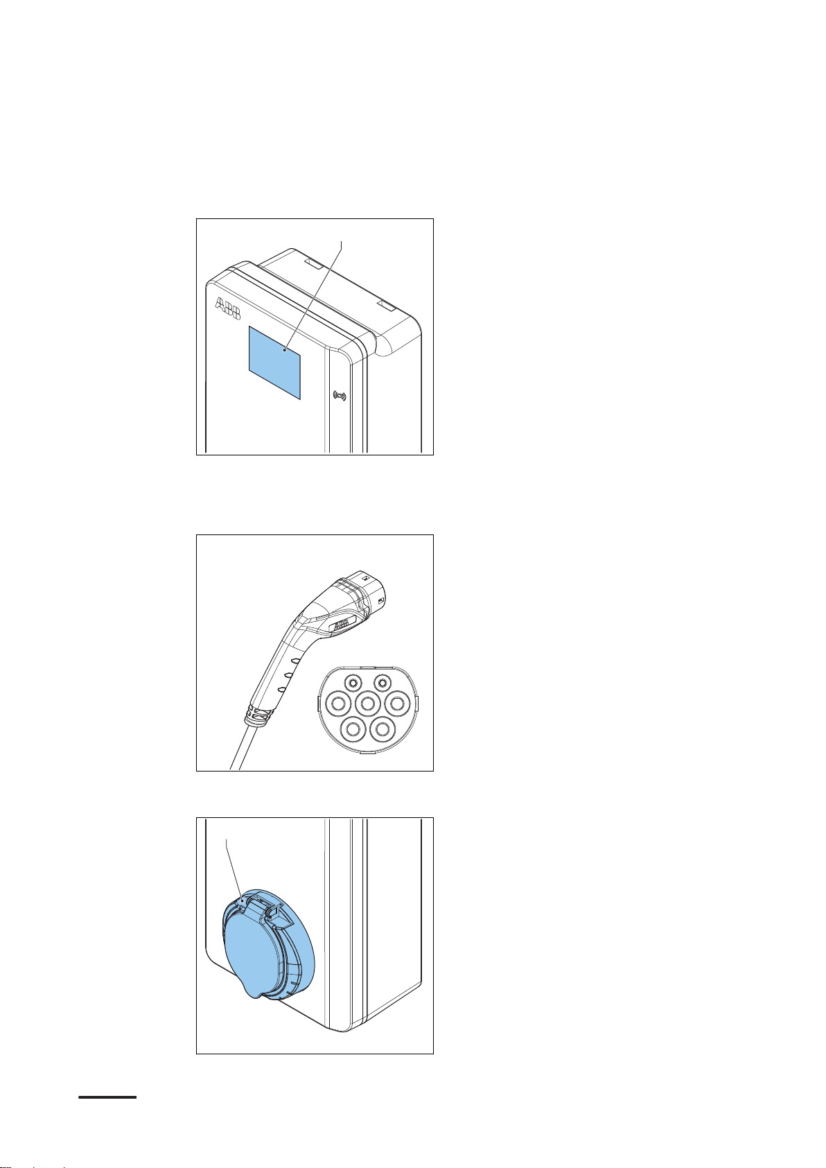
2.7.1 Display
A Display
For more data about the display, refer to section 2.10.
Description
2.7.2 EV charge cable, Type 2
2.7.3 Socket, Type 2
BCM.V3Y01.0-EN | 002 21
A Socket

Description
The socket for an EV charge cable Type 2 is available with or without a shutter.
2.7.4 EV charge cable, Type 1 (UL portfolio)
2.7.5 4G Communication
You can connect to a 4G network.
2.7.6 Load management
Load management makes sure that the available electrical capacity of the building
or home is not exceeded. A number of devices share a grid connection, that has a
maximum capacity. The total power demand of the devices that use the grid
connection must not exceed the grid capacity.
The load management feature prevents that the system exceeds the grid capacity
and prevents damage of the fuses. At times when the current demand is high, the
EVSE decreases the output of current. The current will increase again when there is
availability on the grid.
Also, the load management feature makes sure that the available load is optimally
shared.
22 BCM.V3Y01.0-EN | 002
2.8 Control elements
A
B
C
D
E
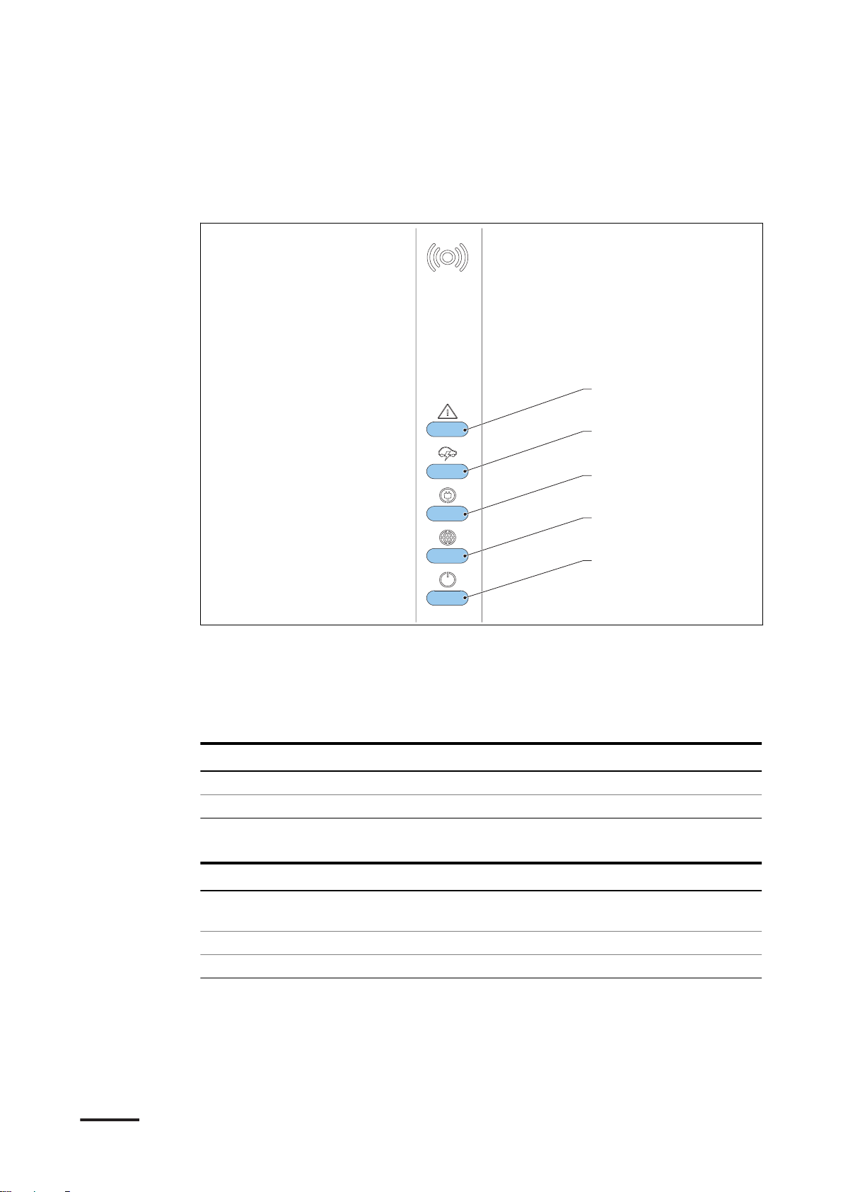
2.8.1 LED indicators
Description
A Error LED
B Charging LED
C Cable and EV detection, and EV
authorization LED
Table 1: Error LED
Status of the LED
On Error
Off No error
Table 2: Charging LED
Status of the LED
On EV is fully charged or has stopped
Off Not charging
Flashing Charging
D Internet connection LED
E EVSE on/off LED
Status of the EVSE
Status of the EVSE
charging
BCM.V3Y01.0-EN | 002 23
 Loading...