

ABB Starters Catalog
Starters
Across the line
Combination
Starters
3
Across the line • Combination
Low Voltage Products & Systems 3.1
ABB Inc. 1SXU000023C0202
Starters
Starters
General information
Field modication kits
A Starters
Start-Stop pushbutton kit – dual element
Contactor/starter Catalog
size number
3
A9 – AF750 MPSSK
For eld installation on NEMA 1 enclosures. Kit includes one dual element
pushbutton and hardware. 1
Start-Stop pushbutton kit
Contactor/starter Catalog
size number
A9 – AF750 MP4SSK4
For eld installation on all enclosures. Kit includes two momentary pushbuttons
and hardware. 1
Fwd-Rev-Stop pushbutton kit
Contactor/starter Catalog
size number
A9 – AF750 MPFRK-4
For eld installation on all enclosures. Kit includes three momentary pushbuttons
and hardware. 1
2 Position selector switch kit
Contactor/starter Catalog
size number
A9 – AF750 MPSL2K-4
For eld installation on all enclosures. Labels for ON-OFF are included. Kits
include mounting hardware. 1
3 Position selector switch kit
Contactor/starter Catalog
size number
A9 – AF750 MPSL3K-4
For eld installation on all enclosures. Labels for HAND-OFF-AUTO are included.
Kits include mounting hardware. 1
Pilot light kits
Contactor/starter
size number
120 MPPLK-41
A9 – AF750 240 MPPLK-42
480V MPPLK-44
For eld installation on all enclosures. 1
Catalog
Voltage
Reset button kits
Contactor/starter Catalog
size number
A9 – AF750 KPR3-104B
For eld installation on all enclosures. 1
1 For use with UL Type 3R, 4, 4X, 12 & 13.
3.2 Low Voltage Products & Systems
1SXU000023C0202 ABB Inc.
Discount schedule FM [U8]
General information
Factory modications
Starters
Control cover accessories — NEMA 1, 3R, 12, 4, 4X
Description
Start-Stop pushbutton A
Fwd-rev-stop pushbutton B
2 position selector switch (Std. On-Off) C
3 position selector switch (Std. Hand-Off-Auto) D
LED Pilot light, Red, RUN (Std) E
LED Pilot light, Green, Off (Std) R
Start-Stop pushbutton & pilot light F
Fwd-rev-stop pushbutton & pilot light G
2 position selector switch & pilot light H
3 position selector switch (HOA) & pilot light J
Fast-slow-stop pushbutton K
Fast-slow-stop pushbutton & pilot light L
Fast-slow-off-auto selector switch M
Emergency stop P
F sufx + 1NO & 1NC auxiliary contact T
J sufx + 1NO & 1NC auxiliary contact U
Pushbutton (standard START) Y
Sufx
code
Special modifications
Description
Contactor
Coil surge suppressor
Relays
Type N control relay (4 pole) N.O. 1
Phase failure phase reversal with over and undervolt-
age relay
Electronic timer (On Delay) 5
Electronic timer (Off Delay) 6
Ground fault protection
For multi-speed controllers
Compelling relay CPR
Accelerating relay ACR
Decelerating DCR
Meter & metering
Current monitor (single CT) CT
Ammeter (single CT w/meter) 2
Voltmeter 2
Voltmeter & Voltmeter switch 2
Elapsed time meter 2
Operation counter 2
Wattmeter 2
Sufx
code
S
2
GF
AM
VM
VMS
ETM
OC
WM
Control circuit transformer — A9 - AF750
Standard size with fused secondary
Sec-
Primary
ondary
208 120 50/60 A A9 - A40 50 50VA V
240 120 50/60 B
480 120 50/60 C A50 - A75 75 100VA
600 120 50/60 D A110 100 200VA Z
208 24 50/60 E
240 24 50/60 F A260 250
480 24 50/60 G
600 24 50/60 H
Coil
Hz
sufx
Starter Size
A9 - A40 1
A145 - A185
Std.
CCT
VA
50 75V
150
Extra VA
CCT
A W
Sufx
code
X
Additional auxiliary contact blocks — A9 - AF750
Contact conguration
1 N.O & 1 N.C. 8
2 N.O & 2 N.C. 9
Sufx
code
Fuses — set of three
Fuse switch size
30A
60A
100A
200A
400A
2 Speed combination starters
Starter size
A9 (A9N00)
A12
A16 (A16N0)
A26 (A26N1)
A30
A40
A50 (A50N2)
A63
A75 (A75N3)
A110
A145 (A145N4)
A185
A210
A260 (A260N5)
A300
AF400
AF460
AF580
AF750
Hazardous location enclosure accessories — NEMA 7 & 9
3R Breather / drain A
Start PB green B
Stop PB red C
St/St dual PB D
Em. Stop mush momentary E
Em. Stop mush maintained F
Black PB N.O. auxiliary G
Black PB N.C. auxiliary H
Pilot light J
Illuminated PB K
Push-to-test pilot light L
Potentiometer M
2-pos Selector Maintained N
2-pos Selector spring L to R P
2-pos Selector spring R to L Q
3-pos Selector sw. main R
3-pos Selector spring L to R S
3-pos Selector spring R to L T
3-pos Selector spring to C U
2-pos Selector key operated V
3-pos Selector key operated W
Item Sufx code
3
1 NEMA 7 and 9.
2 For NEMA 7/9, add $800 to the list price adder of the meter to include a view window on the enclosure door.
Low Voltage Products & Systems 3.3
ABB Inc. 1SXU000023C0202
Discount schedule – Always applied to the
applicable starter discounts
General information
Starters
Catalog number explanation
1 1 S F 1- 2 C 1 J
3
UL rated starter size
1 – A9
2 – A12
3 – A16
4 – A26
5 – A30
6 – A40
7 – A50
8 – A63
9 – A75
A – A110
Starter type
1 – Non-reversing
2 – Reversing
3 – 2 speed, 2 winding or 1 winding
Single phase
S – Single phase (Insert only for single phase)
Combination type
N – Non-fusible disconnect
F – Fusible disconnect
B – Thermal magnetic or electronic trip type circuit breaker (MCCB)
M – Motor Circuit Protection (MCP)
J – Fusible disconnect (with fuses, size base on the HP or FLA x 1.75)
R – Non-fusible disconnect with trailing Class R fuse block with fuses
G – Non-fusible disconnect with trailing Class R fuse block
Enclosure
1 – NEMA / UL Type 1
2 – NEMA / UL Type 12
3 – NEMA / UL Type 3R
4 – NEMA / UL Type 4
X – NEMA / UL Type 4XSS
P – NEMA / UL Type 4X PL
7 – UL Type 7
B – A145
C – A185
D – A210
E – A260
F – A300
G – AF400
H – AF460
T – AF580
U – AF750
J – A9N00 (NEMA size 00)
K – A16N0 (NEMA size 0)
L – A26N1 (NEMA size 1)
M – A50N2 (NEMA size 2)
N – A75N3 (NEMA size 3)
P – A145N4 (NEMA size 4)
Q – A260N5 (NEMA size 5)
R – AF460N6 (NEMA size 6)
S – AF750N7 (NEMA size 7)
Accessories
(See Factory Modications, page 3.3)
Fuse clip
1 – 30A, 600V Class J
2 – 60A, 600V Class J
3 – 100A, 600V Class J
4 – 200A, 600V Class J
5 – 400A, 600V Class J
6 – 600A, 600V Class J
7 – 800A, 600V Class J
8 – 1200A, 600V Class J
9 – 2000A, 600V Class J
Circuit breaker amp rating (200V - 600V)
1 – 15A
2 – 20A
3 – 25A
4 – 30A
5 – 35A
6 – 40A
7 – 50A
8 – 60A
9 – 70A
A – 80A
MCP amp rating (200V - 600V)
1 – 3A
2 – 5A
3 – 10A
4 – 25A
5 – 50A
6 – 100A
B – 90A
C – 100A
D – 125A
E – 150A
F – 175A
G – 200A
H – 225A
J – 250A
K – 300A
L – 350A
7 – 150A
8 – 250A
9 – 400A
A – 450A
B – 500A
C – 600A
M – 400A
N – 450A
O – 500A
P – 600A
Q – 700A
R – 800A
S – 900A
T – 1000A
U – 1200A
V – 2500A
D – 700A
E – 800A
F – 900A
G – 1000A
H – 1200A
J – 2500A
Coil voltage / CCT
Coil voltage selection – A9 - A300
Contactor
Hz
type
60 A 1 2 3 4 5 6 7
50 A 1 2 4 7
Coil voltage selection – AF400 - AF750 1
Hz
50/60 AF 70 71
Control transformer voltage selection chart
Hz
Type 200-208/120 240/120 460 – 480/120 575 – 600/120
A/AF A B C D
50/60
Type 200-208/24 240/24 460 – 480/24 575 – 600/24
A/AF E F G H
Overload range
See Overload relay selection chart, see page 3.6 - 3.7
NOTE: For AF50 - AF300 starters, consult factory.
1 For AF400 - AF750 only.
24 110 120 208 220 240 440 480 500 600
Contactor
type
Volts
Volts
100 - 250 250 - 500
Volts
3.4 Low Voltage Products & Systems
1SXU000023C0202 ABB Inc.
General information
Starters
Motor data
Ampere ratings of 3 phase, AC induction motors
110 – 120V 200 – 208V 220 – 240V 380 – 415V 440 – 480V 550 – 600V
Horse Single Two Three Single Two Three Single Two Three Single Three Single Two Three Single Two Three
power phase phase phase phase phase phase phase phase phase phase phase phase phase phase phase phase phase
1/10 3.0 — — 1.65 — — 1.5 — — 1.0 — — — — — — —
1/8 3.8 — — 2.1 — — 1.9 — — 1.2 — — — — — — —
1/6 4.4 — — 2.4 — — 2.2 — — 1.4 — — — — — — —
1/4 5.8 — — 3.2 — — 2.9 — — 1.8 — — — — — — —
1/3 7.2 — — 4.0 — — 3.6 — — 2.3 — — — — — — —
1/2 9.8 4.0 4.4 5.4 2.2 2.4 4.9 2.0 2.2 3.2 1.3 2.5 1.0 1.1 2.0 0.8 0.9
3/4 13.8 4.8 6.4 7.6 2.6 3.5 6.9 2.4 3.2 4.5 1.8 3.5 1.2 1.6 2.8 1.0 1.3
1 16.0 6.4 8.4 8.8 3.6 4.6 8.0 3.2 4.2 5.1 2.3 4.0 1.6 2.1 3.2 1.3 1.7
1 1/2 20.0 9.0 12.0 11.0 5.0 6.6 10.0 4.5 6.0 6.4 3.3 5.0 2.3 3.0 4.0 1.8 2.4
2 24.0 11.8 13.6 13.2 6.5 7.5 12.0 5.9 6.8 7.7 4.3 6.0 3.0 3.4 4.8 2.4 2.7
3 34.0 16.6 19.2 18.7 9.2 10.6 17.0 8.3 9.6 10.9 6.1 8.5 4.2 4.8 6.8 3.3 3.9
5 56.0 26.4 30.4 30.8 14.5 16.8 28.0 13.2 15.2 17.9 9.7 14.0 6.6 7.6 11.2 5.3 6.1
7 1/2 80.0 38.0 44.0 44.0 21.0 24.2 40.0 19.0 22.0 27.0 14.0 21.0 9.0 11.0 16.0 8.0 9.0
10 100.0 48.0 56.0 55.0 26.4 30.8 50.0 24.0 28.0 33.0 18.0 26.0 12.0 14.0. 20.0 10.0 11.0
15 135.0 72.0 84.0 75.0 39.6 46.2 68.0 36.0 42.0 44.0 27.0 34.0 18.0 21.0 27.0 14.0 17.0
20 — 94.0 108.0 96.8 52.0 60.0 88.0 47.0 54.0 56.0 34.0 44.0 23.0 27.0 35.0 19.0 22.0
25 — 118.0 136.0 121.0 65.0 75.0 110.0 59.0 68.0 70.0 44.0 55.0 29.0 34.0 44.0 24.0 27.0
30 — 138.0 160.0 150.0 76.0 88.0 136.0 69.0 80.0 87.0 51.0 68.0 35.0 40.0 54.0 28.0 32.0
40 — 180.0 208.0 194.0 100.0 115.0 176.0 90.0 104.0 112.0 66.0 88.0 45.0 52.0 70.0 36.0 41.0
50 — 226.0 260.0 238.0 125.0 143.0 216.0 113.0 130.0 139.0 83.0 108.0 56.0 65.0 86.0 45.0 52.0
60 — — — — 147.0 160.0 — 133.0 154.0 — 103.0 — 67.0 77.0 — 53.0 62.0
75 — — — — 183.0 212.0 — 166.0 192.0 — 128.0 — 83.0 96.0 — 66.0 77.0
100 — — — — 240.0 273.0 — 218.0 248.0 — 165.0 — 109.0 124.0 — 87.0 99.0
125 — — — — — 344.0 — — 312.0 — 208.0 — 135.0 156.0 — 108.0 125.0
150 — — — — — 396.0 — — 360.0 — 240.0 — 156.0 180.0 — 125.0 144.0
200 — — — — — 528.0 — — 480.0 — 320.0 — 208.0 240.0 — 167.0 192.0
250 — — — — — 663.0 — — 602.0 — 403.0 — — 302.0 — — 242.0
300 — — — — — — — — — — 482.0 — — 361.0 — — 289.0
350 — — — — — — — — — — 560.0 — — 414.0 — — 336.0
400 — — — — — — — — — — 636.0 — — 477.0 — — 382.0
500 — — — — — — — — — — 786.0 — — 590.0 — — 472.0
NOTE: The above values of full-load currents are typical for motors running at speeds normal for belted motors and motors with normal torque characteristics. When-
ever possible, use the actual motor nameplate full-load current when selecting motor control products.
3
Low Voltage Products & Systems 3.5
ABB Inc. 1SXU000023C0202
Starters
General information
Standardthermaloverloadrelays
Standard–Thermal,TypeTA,Class10&Electronic,TypeE,Class10,20&30
3
A/AL/AE9 – A/AL/AE40 2.2 – 3.1 J TA25DU3.1
A9&TA25
A/AL/AE30 – A/AL/AE40 22 – 32 B TA42DU32
A/AE/AF50 – A/AE/AF75
A50&TA75
A/AF145 – A/AF185 100 – 135 C TA200DU135
A/AF210 – A/AF300 165 – 235 B
A/AF400 – A/AF460 170 – 500 E5
A/AF580 – A/AF750 270 – 800 E8
For
contactor
A/AE/AF110
Settingrange
A
0.1 – 0.16 A TA25DU0.16
0.16 – 0.25 B TA25DU0.25
0.25 – 0.4 C TA25DU0.4
0.4 – 0.63 D TA25DU0.63
0.63 – 1.0 E TA25DU1.0
1.0 – 1.4 F TA25DU1.4
1.3 – 1.8 G TA25DU1.8
1.7 – 2.4 H TA25DU2.4
2.8 – 4.0 K TA25DU4.0
3.5 – 5.0 L TA25DU5.0
4.5 – 6.5 M TA25DU6.5
6.0 – 8.5 N TA25DU8.5
7.5 – 11 P TA25DU11
10 – 14 Q TA25DU14
13 – 19 R TA25DU19
18 – 25 S TA25DU25
24 – 32 T TA25DU32
18 – 25 A TA42DU25
29 – 42 C TA42DU42
18 – 25 A TA75DU25
22 – 32 B TA75DU32
29 – 42 C TA75DU42
36 – 52 D TA75DU52
45 – 63 E TA75DU63
60 – 80 F TA75DU80
29 – 42 C TA80DU42
36 – 52 D TA80DU52
45 – 63 E TA80DU63
60 – 80 F TA80DU80
65 – 90 A TA110DU90
80 – 110 B TA110DU110
65 – 90 A TA200DU90
80 – 110 B TA200DU110
110 – 150 D TA200DU150
130 – 175 E TA200DU175
150 – 200 F TA200DU200
130 – 185 A
220 – 310 C
Replace∆with
suffixcodeon
starter catalog
number
Catalog
number
TA450DU1851
TA450DU2351
TA450DU3101
E500DU5002
E800DU8002
NOTE:Overloadsonthispageareusedasstandardanddonotrequireapriceadder.
1 TA450overloadsrequiremountingkitsforinstallation.
2 Notsuitableforsingle-phasemotorsordirectcurrent(DC)motors.
3.6 Low Voltage Products & Systems
1SXU000023C0202 ABBInc.
General information
Electronic overload relays
Starters
A145 & E200
Optional – Electronic, Type E, Class 10, 20 & 30 Selectable
For
contactor
A/AL/AE9 – A/AL/AE16 0.9 – 2.7 C1 E16DU2.7
A/AL/AE26 – A/AL/AE40
A/AE/AF50 – A/AE/AF75
A/AE/AF110
A/AF145 – A/AF185 65 – 200 E2 E200DU200
A/AF210 – A/AF300 105 – 320 E3 E320DU320
AF400 – AF460 170 – 500 E5 E500DU500
AF580 – AF750 270 – 800 E8 E800DU800
Setting
range
0.1 – 0.32 A1 E16DU0.32
0.3 – 1.0 B1 E16DU1.0
2.0 – 6.3 D1 E16DU6.3
5.7 – 18.9 E1 E16DU18.9
9 – 30 E1 E45DU30
15 – 45 E2 E45DU45
27 – 80 E1 E80DU80
50 – 140 E1 E140DU140
Sufx
code
Catalog
number 1
3
1 Not suitable for single-phase motors and direct current (DC) motors.
2 Included in standard list price of starter.
Low Voltage Products & Systems 3.7
ABB Inc. 1SXU000023C0202
Starters
General information
Enclosures
Type
enclosure (inches) number
A9 – A16 Contactors & starters, blank cover EKA16S-0
3
IP65 A9 – A16 Contactors & starters, start & stop/reset 7 x 3.5 x 5.2 EKA16S-A
A9 – A16 Contactors & starters, reset only EKA16S-R
NEMA 1 A9 – A26 Contactors, non-reversing & reversing starters 11.5 x 7 x 6 EK-N1A9A26
Lift off cover A30 – A75 Contactors, non-reversing & reversing starters 13 x 9 x 7 EK-N1A30A75
A9 – A40 Non-reversing starters + CCT
A9 – A40 Reversing contactors 10 x 8 x 6 EK-11H
NEMA 1 A9 – A40 Reversing starters
Indoor metal A50 – A75 Contactors
hinged cover A50 – A75 Non-reversing starters + CCT 14 x 12 x 8 EK-12
A50 – A75 Reversing starters
A95 – A110 Contactors
A95 – A110 Non-reversing starters + CCT
A9 – A40 Contactors
NEMA 1, 3R A9 – A40 Non-reversing starters + CCT 10 x 8 x 7 EK-W
4, 4X & 12 A9 – A40 Reversing starters
Plastic A50 – A75 Contactors
A50 – A75 Non-reversing starters + CCT
A50 – A75 Reversing starters
A9 – A40 Contactors
A9 – A40 Non-reversing starters
A9 – A40 Reversing contactors
NEMA 12 A9 – A40 Reversing starters
Indoor metal A50 – A75 Contactors + CCT
dusttight A50 – A75 Non-reversing starters + CCT
A50 – A75 Reversing starters
A9 – A40 Contactors + CCT
A9 – A40 Non-reversing starters + CCT
A9 – A40 Reversing contactors
NEMA 3R A9 – A40 Reversing starters
Outdoor A50 – A75 Contactors + CCT
metal A50 – A75 Non-reversing starters + CCT
A50 – A75 Reversing contactors
A50 – A75 Reversing starters
A95 – A110 Contactors + CCT
A110 Non-reversing starters + CCTA95 – A110 Contactors + CCT
A110 Non-reversing starters + CCT
NOTE : (1) All enclosures come standard with reset button and predrilled back panel.
For use with
Dimensions H x W x D Catalog
24 x 12 x 8 EK-13
10 x 8 x 6 EK-24
12 x 10 x 7 EK-W2
14 x 12 x 8 EK-22
10 x 8 x 6 EK-31
14 x 12 x 8 EK-32
3.8 Low Voltage Products & Systems
1SXU000023C0202 ABB Inc.
Discount schedule EE [EE]
General information
X
– Indoors
– Outdoors
– Water
– Dirt/dust
– Corrosion
Legend
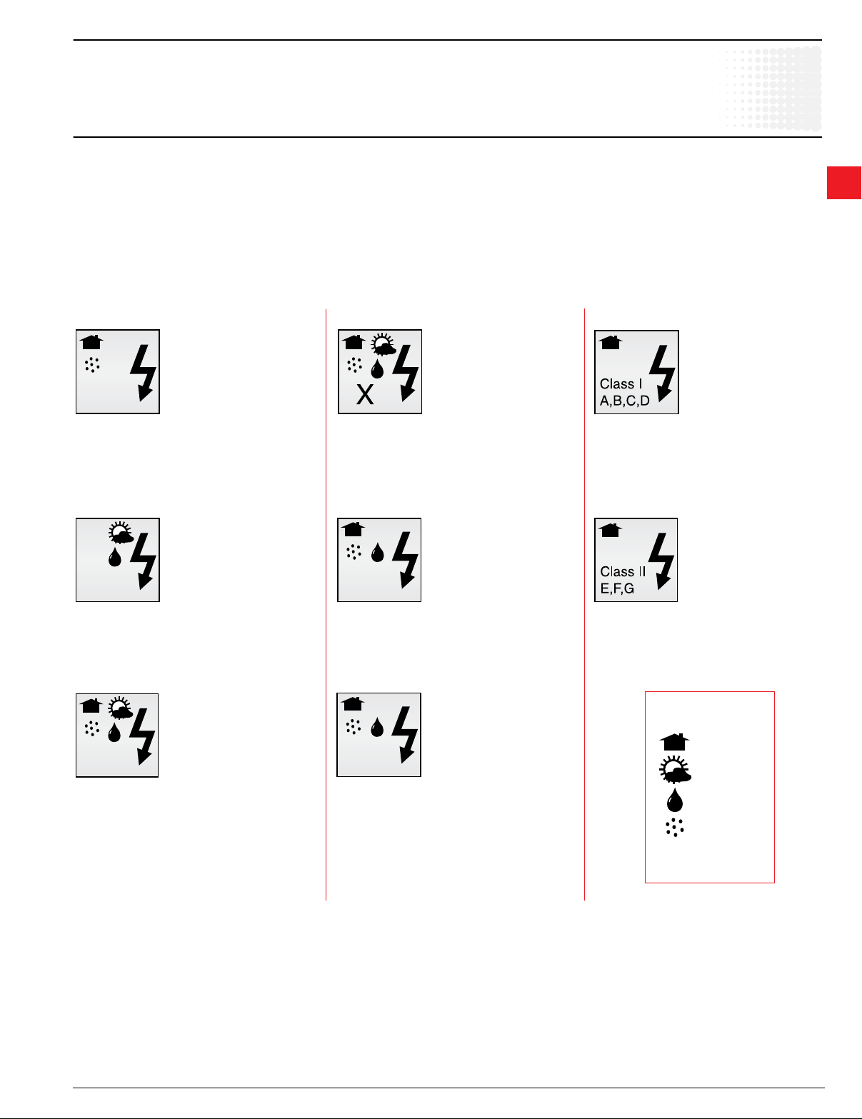
Enclosure rating denitions
Starters
Introduction
An enclosure is a surrounding case constructed to provide a degree of
protection to personnel against accidental contact with the enclosed
equipment and to provide a degree of protection to the enclosed
equipment against specied environmental conditions.
A brief description of the more common types of enclosures used by
the electrical industry relating to their environmental capabilities follows.
Denitions pertaining to nonhazardous locations
Type 1
Enclosures are intended for indoor use
primarily to provide a degree of protection
against limited amounts of falling dirt.
(NEMA Standard 7-15-1991.)
Type 4X
Enclosures are intended for indoor or outdoor
use primarily to provide a degree of protection
against corrosion, windblown dust and
rain, splashing water, hose-directed water
and damage from external ice formation.
(NEMA Standard 1-10-1979)
Refer to NEMA Standards Publication for more information regarding
applications, features and design tests.
Individual NEMA product Standards Publications or third party
certication standards may contain additional requirements for
product testing and performance.
Type 7
Enclosures are intended for indoor use in
locations classied as Class I, Groups, A, B,
C, or D, as dened in the National Electrical
Code. (NEMA Standard 7-15-1991.)
3
Type 3R
Enclosures are intended for outdoor use
primarily to provide a degree of protection
against rain, sleet and damage from external
ice formation. (NEMA Standard 7-15-1991.)
Type 4
Enclosures are intended for indoor or
outdoor use primarily to provide a degree
of protection against windblown dust and
rain, splashing water, hose-directed water
and damage from external ice formation.
(NEMA Standard 1-10-1979.)
Type 12
Enclosures are intended for indoor
use primarily to provide a degree of
protection against circulating dust, falling
dirt, and dripping noncorrosive liquids.
(NEMA Standard 7-15-1991.)
Type 13
Enclosures are intended for indoor
use primarily to provide a degree of
protection against dust, spraying of
water, oil and noncorrosive coolant.
(NEMA Standard 1-10-1979.)
Type 9
Enclosures are intended for indoor use in
locations classied as Class II, Groups E, F, or
G, as dened in the National Electrical Code.
(NEMA Standard 7-15-1991.)
Low Voltage Products & Systems 3.9
ABB Inc. 1SXU000023C0202
Starters
General information
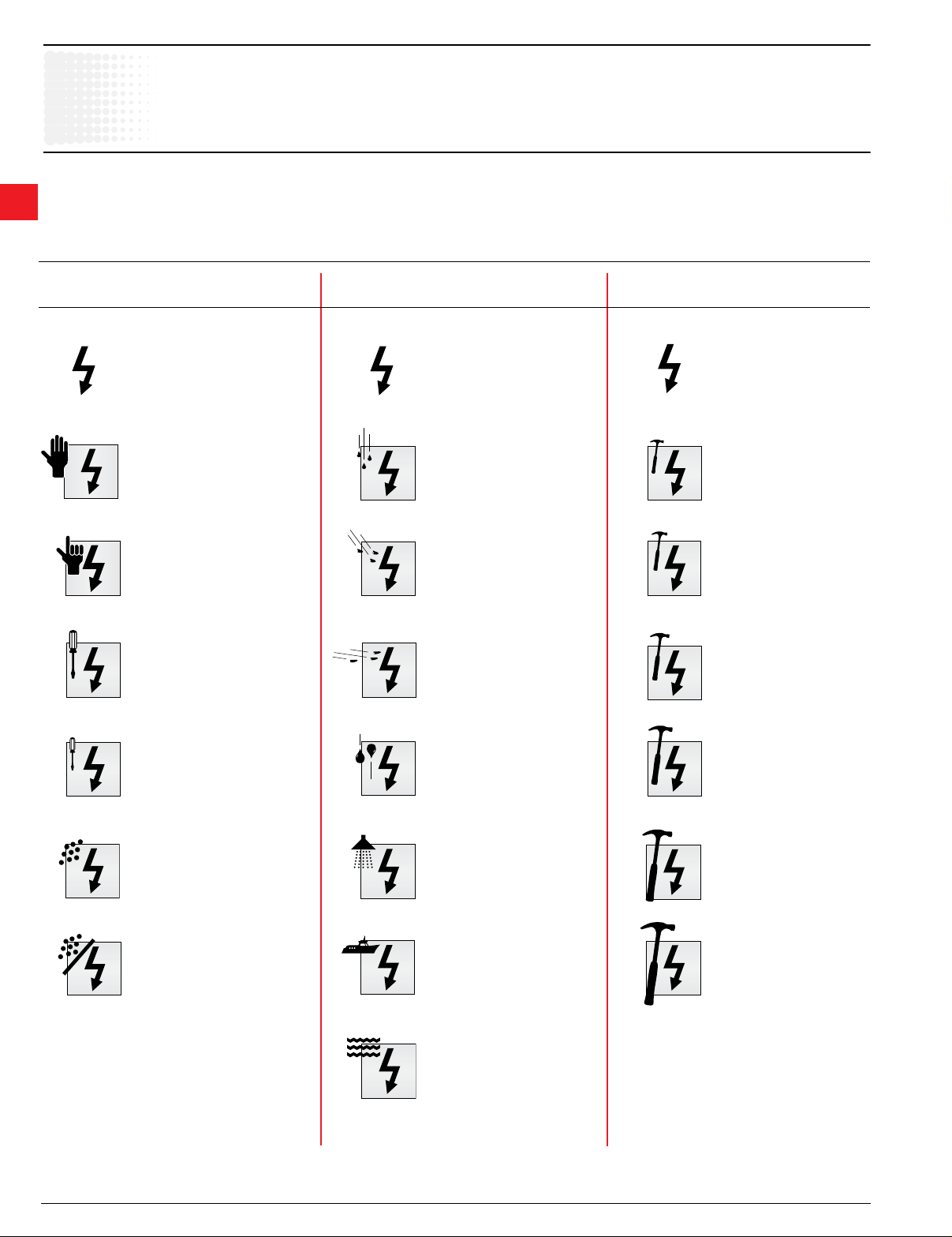
IP Environmental ratings
IP ratings
the French standard NFC 20-010. To rate a device’s degrees of protection, the letters IP are followed by up to
3
three numbers. These numbers are dened as follows:
indicate the degree of protection against dust, liquids and impacts. The IP degrees of protection are dened by
rst number second number third number
protection against solid objects protection against liquids protection against mechanical impacts
no protection
IP
0
protected against solid
objects over 50mm (e.g.
accidental touch by hands.)
1
no protection
IP
0
protected against vertically
falling rain or condensation
1
protected against solid
objects over 12mm (e.g.
2
ngers)
protected against solid
objects over 2.5mm (tools &
3
wires)
protected against direct
sprays of water up to 15°
2
from vertical
protected against sprays to
60° from vertical
3
no protection
IP
0
impact 0.225 joule
150g falling from 15cm
1
impact 0.375 joule
250g falling from15cm
2
impact 0.50 joule
250g falling from 20cm
3
protected against solid
objects over 1mm (small
4
tools & small wires)
protected against dust (no
harmful deposit)
5
totally protected against dust
6
protected against water
sprayed from all directions
4
protected against low
pressure jets of water from
5
all directions
protected from strong jets of
water (e.g. for use on ship
6
decks)
protected against the effects
of immersion between 15cm
and 1m
7
impact 2.00 joule
500g falling from 40cm
5
impact 6.00 joule
1.5kg falling from 40cm
7
impact 20.00 joule
9
5 kg falling from 40cm
3.10 Low Voltage Products & Systems
1SXU000023C0202 ABB Inc.
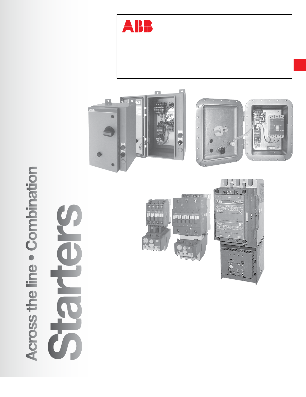
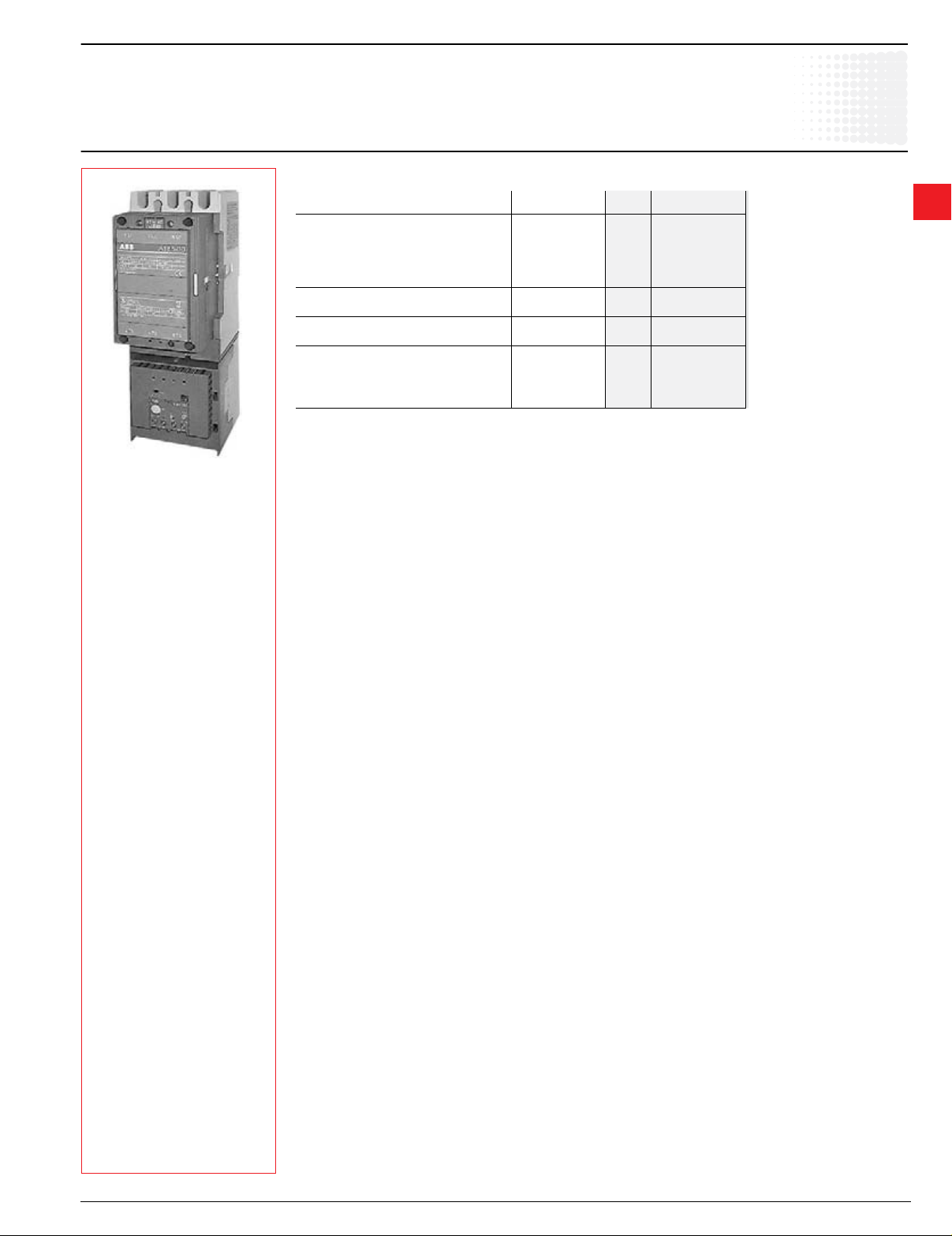
Across the line starters
Open & enclosed
A9 – AF750
Starters
3
Description
A9 – AF750
• Maximum UL horsepower ratings
• UL508A Panel Program, #E105450
• NEMA sizes (00 – 7) available
• Compact space-saving design
• Standard auxiliary contact congurations:
A9 – A40 1 NO
A50 – AF750 1 NO & 1 NC
• Additional auxiliary contact blocks are
available
• Consult factory for DC ratings & DC control
operation
• Fast, snap-on DIN rail mounting (A9 - A110)
• Double break contact design
• Snap-on front and side mounted
accessories include mechanical latch,
pneumatic timer and 1 & 4 pole auxiliary
contact blocks (A9 – A110)
• Easy coil change
• Captive terminal screws
• NEMA, UL, CSA, and most other
international standards
• cUL marked
• Operates over an extended voltage range
of 85% to 110% of rated control voltage
• Screwdriver guide holes
For reduced voltage starters, consult
factory.
Enclosure types
• NEMA 1 (Indoor metal)
• NEMA 3R (Outdoor metal)
• NEMA 12 (Metal dusttight)
• NEMA 4X (Stainless steel)
• NEMA 4 (Water tight)
• NEMA 1, 3R, 4, 4X, & 12 (Plastic)
• IP 65 plastic A9 – A16 starters
• NEMA 7 & 9
Class I, Group C, D, Div 1 & 2
Class II, Groups E, F, & G, D iv 1 & 2
Class III, 4X
Overload relay protection
Starters, sizes A9 – A300, have Class 10
adjustable thermal bimetallic overload relay
protection as standard.
Sizes AF400 – AF750, have selectable Class
10, 20, 30 adjustable electronic overload relay
protection as standard.
Electronic overload relay protection is available
for other starter sizes.
Across the line
Low Voltage Products & Systems 3.11
ABB Inc. 1SXU000023C0202
Starters
Starters
Starter selection by motor horsepower & voltage
Maximum UL/CSA ratings, three phase
Motor horsepower
3-phase, 1800 RPM 1
3
200V 230V 460V 575V Catalog number Catalog number Catalog number
— — — 1/4 11-2C A9-30-10-84 TA25DU0.4 (0.25 – .4)
— — 1/4, 1/3 1/3 11-2D A9-30-10-84 TA25DU0.63 (0.4 – .63)
— — — 1/2 11-2E A9-30-10-84 TA25DU1.0 (0.63 – 1.0)
— — 1/2 3/4 11-2F A9-30-10-84 TA25DU1.4 (1.0 – 1.4)
— — 3/4 — 11-2G A9-30-10-84 TA25DU1.8 (1.3 – 1.8)
— 1/2 1 1.5 11-2H A9-30-10-84 TA25DU2.4 (1.7 – 2.4)
1/2 — 1.5 2 11-2J A9-30-10-84 TA25DU3.1 (2.2 – 3.1)
3/4 3/4 2 — 11-2K A9-30-10-84 TA25DU4.0 (2.8 – 4.0)
— 1 — 3 11-2L A9-30-10-84 TA25DU5.0 (3.5 – 5.0)
1 1.5 3 5 11-2M A9-30-10-84 TA25DU6.5 (4.5 – 6.5)
2 2 5 — 11-2N A9-30-10-84 TA25DU8.5 (6.0 – 8.5)
— — — 7.5 11-2P A9-30-10-84 TA25DU11 (7.5 – 11)
3 3 7.5 10 21-2Q A12-30-10-84 TA25DU14 (10 – 14)
5 5 10 15 31-2R A16-30-10-84 TA25DU19 (13 – 19)
— 7.5 15 20 41-2S A26-30-10-84 TA25DU25 (18 – 25)
7.5 10 20 25 41-2T A26-30-10-84 TA25DU32 (24 – 32)
10 10 — — 51-2B
— — 25 30 51-2C
10 15 30 40 61-2C A40-30-10-84 TA42DU42 (29 – 42)
15 — 40 50 71-2D A50-30-11-84 TA75DU52 (36 – 52)
— 20 — — 71-2E A50-30-11-84 TA75DU63 (45 – 63)
20 — — — 81-2F A63-30-11-84
— — 50 60 81-2F A63-30-11-84 TA75DU80 (60 – 80)
25 30 60 75 91-2F A75-30-11-84
30 40 75 100 A1-2B A110-30-11-84 TA110DU110 (80 – 110)
40 — — — B1-2C
— 50 100 125 B1-2D TA200DU150 (110 – 150)
50 60 125 150 C1-2E A185-30-11-84 TA200DU175 (130 – 175)
60 75 150 200 D1-2E3 A210-30-11-84
100 — 250 300 F1-2E3 A300-30-11-84
125 125, 150 350 400 G1-70E5 AF400-30-11-70
150 200 400 500 H1-70E5 AF460-30-11-70
200 250 500 600 T1-70E8 AF580-30-11-70
250 300 600 700 U1-70E8 AF750-30-11-70
Open
Complete starter
Contactors Overload relays
A30-30-10-84
A145-30-11-84
Starter components
TA42DU32 (22 – 32)
TA42DU42 (29 – 42)
TA200DU135 (100 – 135)
E320DU320 (105-320)75 100 200 250 E1-2E3 A260-30-11-84
E500DU500 (170 – 500)
E800DU800 (270 – 800)
CAUTION: The above ratings are based on average motor FLA. Actual FLA
on the motor nameplate should be used for overload relay setting.
Coil voltage selection
All AC operated catalog numbers include a 120VAC coil. To select other coil
voltages, substitute the code from the Coil Voltage Selection Chart for the two
digits after the last dash in the catalog number.
Ex.: A 240V coil is required for an A75 starter: 91-4F
D.C. operated starters
If DC operation is required, consult factory.
Factory modifications
See page 3.3
NOTE: For motors with RPM greater or less than 1800 RPM, check full load amp rating on motor nameplate to ensure proper overload protection.
For AF50 – AF 300 starters, consult factory.
1 For AF400 - AF750 only.
3.12 Low Voltage Products & Systems
1SXU000023C0202 ABB Inc.
Discount schedule AA [OA] – A9 - A110
AEA [OC] – A145 - AF1650
Coil voltage selection – A9 - A300
Contactor
Hz
type
60 A 1 2 3 4 5 6 7
50 A 1 2 4 7
Coil voltage selection – AF400 - AF750 1
Hz
50/60 AF 70 71
24 110 120 208 220 240 440 480 500 600
Contactor
type
Control transformer voltage selection chart
Hz
Type 200-208/120 240/120 460 – 480/120 575 – 600/120
A/AF A B C D
50/60
Type 200-208/24 240/24 460 – 480/24 575 – 600/24
A/AF E F G H
Volts
Volts
100 - 250 250 - 500
Volts
Starter selection by motor horsepower & voltage
NEMA sizes & ratings, three phase
Starters
NEMA
size
Motor horsepower
3-phase, 1800 RPM 1
200V 230V 460V 575V
Open
Complete starter
Catalog
number
Contactors Overload relays
Catalog
number
Starter components
Catalog
number
— — — 1/4 J1-2C A9N00-30-10-84 TA25DU0.4 (0.25 – .4)
— — — 1/3 J1-2D A9N00-30-10-84 TA25DU0.63 (0.4 – .63)
— — 1/4 1/2 J1-2E A9N00-30-10-84 TA25DU1.0 (0.63 – 1.0)
— 1/4 1/3,1/2 — J1-2F A9N00-30-10-84 TA25DU1.4 (1.0 – 1.4)
— 1/3 3/4 3/4 J1-2G A9N00-30-10-84 TA25DU1.6 (1.3 – 1.6)
00 1/3,1/4 1/2 1 1 J1-2H A9N00-30-10-84 TA25DU2.4 (1.7 – 2.4)
1/2 — — 1.5, 2 J1-2J A9N00-30-10-84 TA25DU3.1 (2.2 – 3.1)
3/4 3/4 1.5, 2 — J1-2K A9N00-30-10-84 TA25DU4.0 (2.8 – 4.0)
— 1 — — J1-2L A9N00-30-10-84 TA25DU5.0 (3.5 – 5.0)
1 1.5 — — J1-2M A9N00-30-10-84 TA25DU6.5 (4.5 – 6.5)
1.5 — — — J1-2N A9N00-30-10-84 TA25DU8.5 (6.0 – 8.5)
— — — 3 K1-2L A16N0-30-10-84 TA25DU5.0 (3.5 – 5.0)
0 — — 3 5 K1-2M A16N0-30-10-84 TA25DU6.5 (4.5 – 6.5)
2 2 5 — K1-2N A16N0-30-10-84 TA25DU8.5 (6.0 – 8.5)
3 3 — — K1-2P A16N0-30-10-84 TA25DU11 (7.5 – 11)
— — — 7.5 L1-2P A26N1-30-10-84 TA25DU11 (7.5 – 11)
1 — — 7.5 10 L1-2Q A26N1-30-10-84 TA25DU14 (10 – 14)
5 5 10 — L1-2R A26N1-30-10-84 TA25DU19 (13 – 19)
7.5 7.5 — — L1-2S A26N1-30-10-84 TA25DU25 (18 – 25)
— — — 15 M1-2R A50N2-30-11-84
2
— — 15 20 M1-2A A50N2-30-11-84 TA75DU25 (18 – 25)
— 10 20 25 M1-2B A50N2-30-11-84 TA75DU32 (22 – 32)
TA25DU19 (13 – 19) 2
10 15 25 — M1-2C A50N2-30-11-84 TA75DU42 (29 – 42)
— — — 30 N1-2C A75N3-30-11-84 TA75DU42 (29 – 42)
3
15 — 30 40 N1-2D A75N3-30-11-84 TA75DU52 (36 – 52)
20 20 40 50 N1-2E A75N3-30-11-84 TA75DU63 (45 – 63)
25 25,30 50 — N1-2F A75N3-30-11-84 TA75DU80 (60 – 80)
— — 60 60, 75 P1-2A A145N4-30-11-84 TA200DU90 (65 – 90)
4 30 40 75 100 P1-2B A145N4-30-11-84 TA200DU110 (80 – 110)
40 50 100 — P1-2C A145N4-30-11-84 TA200DU135 (100 – 135)
50,60,75 60,75,100 125,150,200 200
5
— 100 200 —
6 100, 125 125,150 250, 300 250, 300
150 200 400 400
Q1-2E3
R1-70E5
A260N5-30-11-84 E320DU320 (105-320)
AF460N6-3011-70 E500DU500 (170 - 500)
7 — 250, 300 500, 600 500, 600 S1-70E8 AF750N7-3011-70 E800DU800 (270 - 800)
CAUTION: The above ratings are based on average motor FLA. Actual FLA
on the motor nameplate should be used for overload relay setting.
Coil voltage selection
Coil voltage selection – A9 - A300
Contactor
Hz
type
60 A 1 2 3 4 5 6 7
50 A 1 2 4 7
24 110 120 208 220 240 440 480 500 600
Volts
All AC operated catalog numbers include a 120VAC coil. To select other coil
voltages, substitute the code from the Coil Voltage Selection Chart for the two
digits after the last dash in the catalog number.
Ex.: A 240V coil is required for an A75 starter: N1-4F
D.C. operated starters
If DC operation is required, consult factory.
Factory modifications
See page 3.3
Coil voltage selection – AF400 - AF750 1
Hz
Contactor
type
100 - 250 250 - 500
Volts
50/60 AF 70 71
Control transformer voltage selection chart
Hz
Type 200-208/120 240/120 460 – 480/120 575 – 600/120
A/AF A B C D
50/60
Type 200-208/24 240/24 460 – 480/24 575 – 600/24
Volts
A/AF E F G H
3
NOTE: For motors with RPM greater or less than 1800 RPM, check full load amp rating on motor nameplate to ensure proper overload protection.
For AF50 – AF 300 starters, consult factory.
1 AF400 - AF750 only.
2 Overload to be base mounted.
Low Voltage Products & Systems 3.13
ABB Inc. 1SXU000023C0202
Discount schedule AA [OA] – A9 - A110
AEA [OC] – A145 - AF1650
Starters
Selection by motor horsepower
UL/CSA Starters with electronic overload
Motor horsepower
200V 230V 460V 575V Catalog number Catalog number Catalog number
3
— — — 1/4
— — — 1/2
— — 1/2 3/4
— 1/2 1 1 1/2
1/2 — 1 1/2 2
3/4 3/4 2 —
— 1 — 3
1 1 1/2 3 5
2 2 5 7 1/2 11-2E1 A9-30-10-84
5 5 10 15 31-2E1 A16-30-10-84
— 7 1/2 15 20
7 1/2 10 20 25
10 10 — —
— — 25 30
10 15 30 40 61-2E2 A40-30-10-84 E45DU45 (15-45)
15 20 40 50 71-2E1 A50-30-11-84
25 30 60 75 91-2E1 A75-30-11-84
30 — — —
— 40 75 100
40 50 100 125 B1-2E2 A145-30-11-84
50 60 125 150 C1-2E2 A185-30-11-84
60 75 150 200 D1-2E3 A210-30-11-84
100 — 250 300 F1-2E3 A300-30-11-84
125 5/6 350 400 G1-70E5 AF400-30-11-70
150 200 400 500 H1-70E5 AF460-30-11-70
200 250 500 600 T1-70E8 AF580-30-11-70
250 300 600 700 U1-70E8 AF750-30-11-70
3 Phase, 1800 RPM Contactor Overload relay
11-2B1 A9-30-10-84 E16DU1.0 (0.3 - 1.0)— — 1/4,1/3 1/3
11-2C1 A9-30-10-84 E16DU2.7 (0.9-2.7)— — 3/4 —
11-2D1 A9-30-10-84 E16DU6.3 (2.0-6.3)
41-2E1 A26-30-10-84 E45DU30 (9-30)
51-2E2 A30-30-10-84 E45DU45 (15-45)
A1-2E1 A110-30-11-84 E140DU140 (50-140)
Open
Complete starter
Starter components
E16DU18.9 (5.7-18.9) 3 3 7 1/2 10 21-2E1 A12-30-10-84
E80DU80 (27-80)20 — 50 60 81-2E1 A63-30-11-84
E200DU200 (60-200)
E320DU320 (100-320)75 100 200 250 E1-2E3 A260-30-11-84
E500DU500 (150-500)
E800DU800 (250-800)
3.14 Low Voltage Products & Systems
1SXU000023C0202 ABB Inc.
Discount schedule AA [OA] – A9 - A110
AEA [OC] – A145 - AF1650
Selection by motor horsepower
NEMA Starters with electronic overload
Starters
NEMA
size
1/3,1/4 1/2 1 1 J1-2C1 A9N00-30-10-84
00
0
1
2
3
4
5
6
7 —
Motor horsepower Open
3-phase, 1800 RPM Contactors
200V 230V 460V 575V
— — — 1/4 J1-2A1 A9N00-30-10-84 E16DU0.32 (0.1 - 0.32)
— — — 1/3 J1-2B1 A9N00-30-10-84
— — 1/4 1/2 J1-2B1 A9N00-30-10-84
— 1/4 1/3,1/2 — J1-2C1 A9N00-30-10-84
1/2 — — 1.5, 2 J1-2D1 A9N00-30-10-84
3/4 3/4 1.5, 2 —
— 1 — — J1-2D1 A9N00-30-10-84
1 1.5 — — J1-2D1 A9N00-30-10-84
1.5 — — — J1-2E1 A9N00-30-10-84 E16DU18.9 (5.7 - 18.9)
— — — 3 K1-2D1 A16N0-30-10-84
— — 3 5 K1-2D1 A16N0-30-10-84
2 2 5 — K1-2E1 A16N0-30-10-84
3 3 — — K1-2E1 A16N0-30-10-84
— — — 7.5 L1-2E1 A26N1-30-10-84
— — 7.5 10 L1-2E1 A26N1-30-10-84
5 5 10 — L1-2E1 A26N1-30-10-84
7.5 7.5 — — L1-2E1 A26N1-30-10-84
— — — 15 M1-2E1 A50N2-30-11-84 E45DU45 (15 - 45)
— — 15 20 M1-2E1 A50N2-30-11-84
— 10 20 25
10 15 25 — M1-2E1 A50N2-30-11-84 E80DU80 (27 - 80)
— — — 30 N1-2E1 A75N3-30-11-84
15 — 30 40 N1-2E1 A75N3-30-11-84
20 20 40 50 N1-2E1 A75N3-30-11-84
25 25,30 50 — N1-2E1 A75N3-30-11-84
— — 60 60, 75 P1-2E2 A145N4-30-11-84
40 50 100 — P1-2E2 A145N4-30-11-84
50
60
60
75
100
— 100 200 —
100
125
150 200 400 400
125
150
250
300
125
75
150
200
250
300
500
600
200
250
300
500
600
Complete starter
Catalog
number
J1-2D1 A9N00-30-10-84
M1-2E1 A50N2-30-11-84
Q1-2E3 A260N5-30-11-84 E320DU320 (105-320)
R1-70E5 AF460N6-3011-70 E500DU500 (170 - 500)
S1-70E8 AF750N7-3011-70 E800DU800 (270 - 800)
Catalog
number
Starter components
E16DU1.0 (0.3 - 1.0)
E16DU2.7 (0.9 - 2.7)— 1/3 3/4 3/4 J1-2C1 A9N00-30-10-84
E16DU6.3 (2.0 - 6.3)
E16DU6.3 (2.0 - 6.3)
E16DU18.9 (5.7 - 18.9)
E45DU30 (9 - 30)
E45DU45 (15 - 45)
E80DU80 (27 - 80)
E200DU200 (60 - 200)30 40 75 100 P1-2E2 A145N4-30-11-84
Overload relays
Catalog
number
3
Low Voltage Products & Systems 3.15
ABB Inc. 1SXU000023C0202
Open Enclosed
Discount schedule AA [OA] AAE [EA] – A9 - A110
AEA [OC] AEAE [EC] – A145 - AF1650
Starters
Non-reversing
A9 - AF750
Three phase
3
UL motor
switching
current
Contactor
size
Maximum ratings - UL Listed
Maximum motor horsepower ratings
200/208V 230/240V 480/480V 575/600V
Catalog
number
Open
type
UL Type 1
(Indoor metal)
Catalog
number
UL rated
9 A9 2 2 5 7.5 11-2∆ 111-2∆ 113-2∆
11 A12 3 3 7.5 10 21-2∆ 211-2∆ 213-2∆
17 A16 5 5 10 15 31-2∆ 311-2∆ 313-2∆
28 A26 7.5 10 20 25 41-2∆ 411-2∆ 413-2∆
34 A30 10 10 25 30 51-2∆ 511-2∆ 513-2∆
42 A40 10 15 30 40 61-2∆ 611-2∆ 613-2∆
54 A50 15 20 40 50 71-2∆ 711-2∆ 713-2∆
65 A63 20 25 50 50 81-2∆ 811-2∆ 813-2∆
80 A75 25 30 60 75 91-2∆ 911-2∆ 913-2∆
110 A110 30 40 75 100 A1-2∆ A11-2∆ A13-2∆
130 A145 40 50 100 125 B1-2∆ B11-2∆ B13-2∆
156 A185 50 60 125 150 C1-2∆ C11-2∆ C13-2∆
192 A210 60 75 150 200 D1-2∆ D11-2∆ D13-2∆
248 A260 75 100 200 250 E1-2∆ E11-2∆ E13-2∆
302 A300 100 100 250 300 F1-2∆ F11-2∆ F13-2∆
414 AF400 125 150 350 400 G1-70∆ G11-70∆ G13-70∆
480 AF460 150 200 400 500 H1-70∆ H11-70∆ H13-70∆
590 AF580 200 250 500 600 T1-70∆ T11-70∆ T13-70∆
810 AF750 250 300 600 700 U1-70∆ U11-70∆ U13-70∆
NEMA rated
NEMA Contactor Continuous
size size current
200V 230V 460/575V
00 A9 9 1.5 1.5 2 J1-2∆ J11-2∆ J13-2∆
0 A16 18 3 3 5 K1-2∆ K11-2∆ K13-2∆
1 A26 27 7.5 7.5 10 L1-2∆ L11-2∆ L13-2∆
2 A50 45 10 15 25 M1-2∆ M11-2∆ M13-2∆
3 A75 90 25 30 50 N1-2∆ N11-2∆ N13-2∆
4 A145 135 40 50 100 P1-2∆ P11-2∆ P13-2∆
5 AF260 270 75 100 200 Q1-2∆ Q11-2∆ Q13-2∆
6 AF460 540 150 200 400 R1-70∆ R11-70∆ R13-70∆
7 AF750 810 — 300 600 S1-70∆ S11-70∆ S13-70∆
∆ Overload relay sufx code. Select from the overload relay selection chart on pages 3.6 - 3.7.
UL type 3R
(Outdoor metal)
Catalog
number
Coil voltage selection
All AC operated catalog numbers include a 120VAC coil. To select other coil
voltages, substitute the code from the Coil Voltage Selection Chart for the sufx
code after the last dash in the catalog number.
Ex.: A 240V coil is required for an A75 starter: 91-4F
D.C. operated starters
If DC operation is required, consult factory.
Factory modifications
Coil voltage selection – A9 - A300
Contactor
Hz
type
60 A 1 2 3 4 5 6 7
50 A 1 2 4 7
Coil voltage selection – AF400 - AF750 1
Hz
24 110 120 208 220 240 440 480 500 600
Contactor
type
Volts
Volts
100 - 250 250 - 500
50/60 AF 70 71
See page 3.3
Control transformer option
Contactor VA
size rating
A9 – A40 50
A9 – A40 (N7 & 9) 50
A50 – A75 75
Control transformer voltage selection chart
Hz
Type 200-208/120 240/120 460 – 480/120 575 – 600/120
A/AF A B C D
50/60
Type 200-208/24 240/24 460 – 480/24 575 – 600/24
Volts
A/AF E F G H
A95 – A110 100
A145 – A185 150
A210 – A300 250
AF400 – AF460 150
AF580 – AF750 250
Reference page 3.3 for Extra VA under all (Control Transformer Options chart)
NOTE: For AF50 – AF 300 starters, consult factory.
1 AF400 - AF750 only.
2 NEMA 7 & 9 Enclosed starter only.
3.16 Low Voltage Products & Systems
1SXU000023C0202 ABB Inc.
Open Enclosed
Discount schedule AA [OA] AAE [EA] – A9 - A110
AEA [OC] AEAE [EC] – A145 - AF1650
Non-reversing
A9 - AF750
Three phase
Starters
UL Type 12
(Metal dustight)
Catalog
number
112-2∆ 114-2∆ 11X-2∆ 11P-2∆ 117-2∆
212-2∆ 214-2∆ 21X-2∆ 21P-2∆ 217-2∆
312-2∆ 314-2∆ 31X-2∆ 31P-2∆ 317-2∆
412-2∆ 414-2∆ 41X-2∆ 41P-2∆ 417-2∆
512-2∆ 514-2∆ 51X-2∆ 51P-2∆ 517-2∆
612-2∆ 614-2∆ 61X-2∆ 61P-2∆ 617-2∆
712-2∆ 714-2∆ 71X-2∆ 71P-2∆ 717-2∆
812-2∆ 814-2∆ 81X-2∆ 81P-2∆ 817-2∆
912-2∆ 914-2∆ 91X-2∆ 91P-2∆ 917-2∆
A12-2∆ A14-2∆ A1X-2∆ A1P-2∆ A17-2∆
B12-2∆ B14-2∆ B1X-2∆ B1P-2∆ B17-2∆
C12-2∆ C14-2∆ C1X-2∆ C1P-2∆ C17-2∆
D12-2∆ D14-2∆ D1X-2∆ D1P-2∆ D17-2∆
E12-2∆ E14-2∆ E1X-2∆ E1P-2∆ E17-2∆
F12-2∆ F14-2∆ F1X-2∆ F1P-2∆ F17-2∆
G12-70∆ G14-70∆ G1X-70∆ Consult factory Consult factory
H12-70∆ H14-70∆ H1X-70∆ Consult factory Consult factory
T12-70∆ T14-70∆ T1X-70∆ Consult factory Consult factory
U12-70∆ U14-70∆ U1X-70∆ Consult factory Consult factory
J12-2∆ J14-2∆ J1X-2∆ J1P-2∆ J17-2∆
K12-2∆ K14-2∆ K1X-2∆ K1P-2∆ K17-2∆
L12-2∆ L14-2∆ L1X-2∆ L1P-2∆ L17-2∆
M12-2∆ M14-2∆ M1X-2∆ M1P-2∆ M17-2∆
N12-2∆ N14-2∆ N1X-2∆ N1P-2∆ N17-2∆
P12-2∆ P14-2∆ P1X-2∆ P1P-2∆ P17-2∆
Q12-2∆ Q14-2∆ Q1X-2∆ Q1P-2∆ Q17-2∆
R12-70∆ R14-70∆ R1X-70∆ Consult factory Consult factory
S12-70∆ S14-70∆ S1X-70∆ Consult factory Consult factory
∆ Overload relay sufx code. Select from the overload relay selection chart on pages 3.6 - 3.7.
Catalog
number
UL Type 4
(Watertight)
UL Type 4X
(Stainless steel)
Catalog
number
UL rate
NEMA rate
UL Type 1, 3R, 4, 4X & 12
(Plastic)
Catalog
number
UL Type 7 & 9 non-reversing
Catalog
number
(Explosion proof)
3
Low Voltage Products & Systems 3.17
ABB Inc. 1SXU000023C0202
Enclosed Explosion-proof
Discount schedule AAE [EA] AXE [EB] – A9 - A110
AEAE [EC] – A145 - AF1650
Starters
Non-reversing
A9 - A185
Single phase
UL motor
switching
current
3
9 A9 1/2 1 11S-2∆ 11S1-2∆
11 A12 3/4 2 21S-2∆ 21S1-2∆
17 A16 1 3 31S-2∆ 31S1-2∆
28 A26 1.5 5 41S-2∆ 41S1-2∆
34 A30 2 7.5 51S-2∆ 51S1-2∆
42 A40 3 7.5 61S-2∆ 61S1-2∆
54 A50 3 7.5 71S-2∆ 71S1-2∆
65 A63 5 10 81S-2∆ 81S1-2∆
80 A75 7.5 15 91S-2∆ 91S1-2∆
110 A110 10 20 A1S-2∆ A1S1-2∆
130 A145 10 25 B1S-2∆ B1S1-2∆
156 A185 15 30 C1S-2∆ C1S1-2∆
NEMA
size
00 A9 9 1/3 1 J1S-2∆ J1S1-2∆
0 A16 18 1 2 K1S-2∆ K1S1-2∆
1 A26 27 2 3 L1S-2∆ L1S1-2∆
2 A50 45 3 7.5 M1S-2∆ M1S1-2∆
∆ Overload relay sufx code. Select from the overload relay selection chart on pages 3.6 - 3.7.
Contactor
size
Contactor
size
Continuous
current
Coil voltage selection
All AC operated catalog numbers include a 120VAC coil. To select other coil
voltages, substitute the code from the Coil Voltage Selection Chart for the sufx
code after the last dash in the catalog number.
Ex.: A 240V coil is required for an A75 starter: 91S-4F
D.C. operated starters
If DC operation is required, consult factory.
Factory modifications
See page 3.3
Maximum ratings - UL Listed
Maximum motor horsepower ratings
115V 230V
UL rated
NEMA rated
115V 200V
Coil voltage selection – AF400 - AF750 1
Control transformer voltage selection chart
50/60
Hz
50/60 AF 70 71
Hz
Contactor
type
Type 200-208/120 240/120 460 – 480/120 575 – 600/120
A/AF A B C D
Type 200-208/24 240/24 460 – 480/24 575 – 600/24
A/AF E F G H
Open
type
Catalog
number
100 - 250 250 - 500
Volts
Volts
UL Type 1
(Indoor metal)
Catalog
number
Control transformer option
Contactor VA
size rating
A9 – A30 50
A40 – A75 75
A95 – A110 100
A145 – A185 150
3.18 Low Voltage Products & Systems
1SXU000023C0202 ABB Inc.
Open Enclosed
Discount schedule AA [OA] AAE [EA] – A9 - A110
AEA [OC] AEAE [EC] – A145 - AF1650
Non-reversing
A9 - A185
Single phase
Starters
UL Type 3R
(Outdoor metal)
Catalog
number
11S3-2∆ 11S2-2∆ 11S4-2∆ 11SX-2∆ 11SP-2∆
21S3-2∆ 21S2-2∆ 21S4-2∆ 21SX-2∆ 21SP-2∆
31S3-2∆ 31S2-2∆ 31S4-2∆ 31SX-2∆ 31SP-2∆
41S3-2∆ 41S2-2∆ 41S4-2∆ 41SX-2∆ 41SP-2∆
51S3-2∆ 51S2-2∆ 51S4-2∆ 51SX-2∆ 51SP-2∆
61S3-2∆ 61S2-2∆ 61S4-2∆ 61SX-2∆ 61SP-2∆
71S3-2∆ 71S2-2∆ 71S4-2∆ 71SX-2∆ 71SP-2∆
81S3-2∆ 81S2-2∆ 81S4-2∆ 81SX-2∆ 81SP-2∆
91S3-2∆ 91S2-2∆ 91S4-2∆ 91SX-2∆ 91SP-2∆
A1S3-2∆ A1S2-2∆ A1S4-2∆ A1SX-2∆ A1SP-2∆
B1S3-2∆ B1S2-2∆ B1S4-2∆ B1SX-2∆ B1SP-2∆
C1S3-2∆ C1S2-2∆ C1S4-2∆ C1SX-2∆ C1SP-2∆
J1S3-2∆ J1S2-2∆ J1S4-2∆ J1SX-2∆ J1SP-2∆
K1S3-2∆ K1S2-2∆ K1S4-2∆ K1SX-2∆ K1SP-2∆
L1S3-2∆ L1S2-2∆ L1S4-2∆ L1SX-2∆ L1SP-2∆
M1S3-2∆ M1S2-2∆ M1S4-2∆ M1SX-2∆ M1SP-2∆
∆ Overload relay sufx code. Select from the overload relay selection chart on pages 3.6 - 3.7.
UL Type 12
(Metal dustight)
Catalog
number
UL Type 4
(Watertight)
Catalog
number
UL rated
NEMA rated
UL Type 4X
(Stainless steel)
Catalog
number
UL Type 1, 3R, 4, 4X & 12
(Plastic)
Catalog
number
3
Low Voltage Products & Systems 3.19
ABB Inc. 1SXU000023C0202
Enclosed
Discount schedule AAE [EA] – A9 - A110
AEAE [EC] – A145 - AF1650
Starters
Reversing
A9 - AF750
Three phase
3
UL motor
switching
current
Contactor
size
Maximum ratings - UL Listed
Maximum motor horsepower ratings
200/208V 230/240V 480/480V 575/600V
Catalog
number
Open
type
UL Type 1
(Indoor metal)
Catalog
number
UL rated
9 A9 2 2 5 7.5 12-2∆ 121-2∆ 123-2∆
11 A12 3 3 7.5 10 22-2∆ 221-2∆ 223-2∆
17 A16 5 5 10 15 32-2∆ 321-2∆ 323-2∆
28 A26 7.5 10 20 25 42-2∆ 421-2∆ 423-2∆
34 A30 10 10 25 30 52-2∆ 521-2∆ 523-2∆
42 A40 10 15 30 40 62-2∆ 621-2∆ 623-2∆
54 A50 15 20 40 50 72-2∆ 721-2∆ 723-2∆
65 A63 20 25 50 50 82-2∆ 821-2∆ 823-2∆
80 A75 25 30 60 75 92-2∆ 921-2∆ 923-2∆
110 A110 30 40 75 100 A2-2∆ A21-2∆ A23-2∆
130 A145 40 50 100 125 B2-2∆ B21-2∆ B23-2∆
156 A185 50 60 125 150 C2-2∆ C21-2∆ C23-2∆
192 A210 60 75 150 200 D2-2∆ D21-2∆ D23-2∆
248 A260 75 100 200 250 E2-2∆ E21-2∆ E23-2∆
302 A300 100 100 250 300 F2-2∆ F21-2∆ F23-2∆
414 AF400 125 150 350 400 G2-70∆ G21-70∆ G23-70∆
480 AF460 150 200 400 500 H2-70∆ H21-70∆ H23-70∆
590 AF580 200 250 500 600 T2-70∆ T21-70∆ T23-70∆
810 AF750 250 300 600 700 U2-70∆ U21-70∆ U23-70∆
NEMA rated
NEMA Contactor Continuous
size size current
200V 230V 460/575V
00 A9 9 1.5 1.5 2 J2-2∆ J21-2∆ J23-2∆
0 A16 18 3 3 5 K2-2∆ K21-2∆ K23-2∆
1 A26 27 7.5 7.5 10 L2-2∆ L21-2∆ L23-2∆
2 A50 45 10 15 25 M2-2∆ M21-2∆ M23-2∆
3 A75 90 25 30 50 N2-2∆ N21-2∆ N23-2∆
4 A145 135 40 50 100 P2-2∆ P21-2∆ P23-2∆
5 A260 270 75 100 200 Q2-2∆ Q21-2∆ Q23-2∆
6 AF460 540 150 200 400 R2-70∆ R21-70∆ R23-70∆
7 AF750 810 — 300 600 S2-70∆ S21-70∆ S23-70∆
∆ Overload relay sufx code. Select from the overload relay selection chart on pages 3.6 - 3.7.
UL type 3R
(Outdoor metal)
Catalog
number
Coil voltage selection
All AC operated catalog numbers include a 120VAC coil. To select other coil
voltages, substitute the code from the Coil Voltage Selection Chart for the sufx
code after the last dash in the catalog number.
Coil voltage selection – A9 - A300
Contactor
Hz
type
60 A 1 2 3 4 5 6 7
50 A 1 2 4 7
24 110 120 208 220 240 440 480 500 600
Volts
Ex.: A 240V coil is required for an A75 starter: 92-4F
D.C. operated starters
If DC operation is required, consult factory.
Factory modifications
See page 3.3
Control transformer option
Contactor VA
size rating
A9 – A40 50
Coil voltage selection – AF400 - AF750 1
Hz
Contactor
type
100 - 250 250 - 500
Volts
50/60 AF 70 71
Control transformer voltage selection chart
Hz
Type 200-208/120 240/120 460 – 480/120 575 – 600/120
A/AF A B C D
50/60
Type 200-208/24 240/24 460 – 480/24 575 – 600/24
Volts
A/AF E F G H
A50 – A75 75
A95 – A110 100
A145 – A185 150
A210 – A300 250
AF400 – AF460 150
AF580 – AF750 250
Reference page 3.3 for Extra VA under all (Control Transformer Options chart)
NOTE: For AF50 – AF 300 starters, consult factory.
1 AF400 - AF750 only.
3.20 Low Voltage Products & Systems
1SXU000023C0202 ABB Inc.
Open Enclosed
Discount schedule AA [OA] AAE [EA] – A9 - A110
AEA [OC] AEAE [EC] – A145 - AF1650
Reversing
A9 - AF750
Three phase
Starters
UL Type 12
(Metal dustight)
Catalog
number
122-2∆ 124-2∆ 12X-2∆ 12P-2∆
222-2∆ 224-2∆ 22X-2∆ 22P-2∆
322-2∆ 324-2∆ 32X-2∆ 32P-2∆
422-2∆ 424-2∆ 42X-2∆ 42P-2∆
522-2∆ 524-2∆ 52X-2∆ 52P-2∆
622-2∆ 624-2∆ 62X-2∆ 62P-2∆
722-2∆ 724-2∆ 72X-2∆ 72P-2∆
822-2∆ 824-2∆ 82X-2∆ 82P-2∆
922-2∆ 924-2∆ 92X-2∆ 92P-2∆
A22-2∆ A24-2∆ A2X-2∆ A2P-2∆
B22-2∆ B24-2∆ B2X-2∆ B2P-2∆
C22-2∆ C24-2∆ C2X-2∆ C2P-2∆
D22-2∆ D24-2∆ D2X-2∆ D2P-2∆
E22-2∆ E24-2∆ E2X-2∆ E2P-2∆
F22-2∆ F24-2∆ F2X-2∆ F2P-2∆
G22-70∆ G24-70∆ G2X-70∆ Consult factory
H22-70∆ H24-70∆ H2X-70∆ Consult factory
T22-70∆ T24-70∆ T2X-70∆ Consult factory
U22-70∆ U24-70∆ U2X-70∆ Consult factory
J22-2∆ J24-2∆ J2X-2∆ J2P-2∆
K22-2∆ K24-2∆ K2X-2∆ K2P-2∆
L22-2∆ L24-2∆ L2X-2∆ L2P-2∆
M22-2∆ M24-2∆ M2X-2∆ M2P-2∆
N22-2∆ N24-2∆ N2X-2∆ N2P-2∆
P22-2∆ P24-2∆ P2X-2∆ P2P-2∆
Q22-2∆ Q24-2∆ Q2X-2∆ Q2P-2∆
R22-70∆ R24-70∆ R2X-70∆ Consult factory
S22-70∆ S24-70∆ S2X-70∆ Consult factory
∆ Overload relay sufx code. Select from the overload relay selection chart on pages 3.6 - 3.7.
Catalog
number
UL Type 4
(Watertight)
UL rated
NEMA rated
UL Type 4X
(Stainless steel)
Catalog
number
UL Type 1, 3R, 4, 4X & 12
Catalog
number
(Plastic)
3
Low Voltage Products & Systems 3.21
ABB Inc. 1SXU000023C0202
Enclosed
Discount schedule AAE [EA] – A9 - A110
AEAE [EC] – A145 - AF1650
Starters
2 Speed, 1 winding
A9 - AF750
Three phase
UL motor
switching
3
current
∆ Overload relay sufx code. Select from the overload relay selection chart on pages 3.6 - 3.7. 1st ∆ low speed; 2nd ∆ high speed.
Contactor
size
9 A9 2 2 5 7.5 13-2∆1∆ 131-2∆1∆ 133-2∆1∆
11 A12 3 3 7.5 10 23-2∆1∆ 231-2∆1∆ 233-2∆1∆
17 A16 5 5 10 15 33-2∆1∆ 331-2∆1∆ 333-2∆1∆
28 A26 7.5 10 20 25 43-2∆1∆ 431-2∆1∆ 433-2∆1∆
34 A30 10 10 25 30 53-2∆1∆ 531-2∆1∆ 533-2∆1∆
42 A40 10 15 30 40 63-2∆1∆ 631-2∆1∆ 633-2∆1∆
54 A50 15 20 40 50 73-2∆1∆ 731-2∆1∆ 733-2∆1∆
65 A63 20 25 50 50 83-2∆1∆ 831-2∆1∆ 833-2∆1∆
80 A75 25 30 60 75 93-2∆1∆ 931-2∆1∆ 933-2∆1∆
110 A110 30 40 75 100 A3-2∆1∆ A31-2∆1∆ A33-2∆1∆
130 A145 40 50 100 125 B3-2∆1∆ B31-2∆1∆ B33-2∆1∆
156 A185 50 60 125 150 C3-2∆1∆ C31-2∆1∆ C33-2∆1∆
192 A210 60 75 150 200 D3-2∆1∆ D31-2∆1∆ D33-2∆1∆
248 A260 75 100 200 250 E3-2∆1∆ E31-2∆1∆ E33-2∆1∆
302 A300 100 100 250 300 F3-2∆1∆ F31-2∆1∆ F33-2∆1∆
414 AF400 125 150 350 400 G3-70∆1∆ G31-70∆1∆ G33-70∆1∆
480 AF460 150 200 400 500 H3-70∆1∆ H31-70∆1∆ H23-70∆1∆
590 AF580 200 250 500 600 T3-70∆1∆ T31-70∆1∆ T33-70∆1∆
810 AF750 250 300 600 700 U3-70∆1∆ U31-70∆1∆ U33-70∆1∆
NEMA Contactor Continuous
size size current
00 A9 9 1.5 1.5 2 J3-2∆1∆ J31-2∆1∆ J33-2∆1∆
0 A16 18 3 3 5 K3-2∆1∆ K31-2∆1∆ K33-2∆1∆
1 A26 27 7.5 7.5 10 L3-2∆1∆ L31-2∆1∆ L33-2∆1∆
2 A50 45 10 15 25 M3-2∆1∆ M31-2∆1∆ M33-2∆1∆
3 A75 90 25 30 50 N3-2∆1∆ N31-2∆1∆ N33-2∆1∆
4 A145 135 40 50 100 P3-2∆1∆ P31-2∆1∆ P33-2∆1∆
5 A260 270 75 100 200 Q3-2∆1∆ Q31-2∆1∆ Q33-2∆1∆
6 AF460 540 150 200 400 R3-70∆1∆ R31-70∆1∆ R33-70∆1∆
7 AF750 810 — 300 600 S3-70∆1∆ S31-70∆1∆ S33-70∆1∆
Maximum ratings - UL Listed
Maximum motor horsepower ratings
200/208V 230/240V 480/480V 575/600V
200V 230V 460/575V
Description
Motors that have separate windings for each speed provide more combinations of
speed variations. Multi-speed starters from ABB Control are available for constant
horsepower, constant torque and variable torque motors.
Constant horsepower
Motors that maintain the same horsepower regardless of speed are called
constant horsepower motors. These motors are used in applications like
metal working.
Constant torque
Motors that maintain constant torque at all speeds are called constant torque
motors. In applications like conveyors, horsepower varies directly with speed.
Variable torque motors
Motors that produce a torque characteristic which varies as the square of
the speed are called variable torque motors and are used in applications like
blowers and fans.
Open
type
Catalog
number
UL rated
NEMA rated
UL Type 1
(Indoor metal)
Catalog
number
Coil voltage selection
All AC operated catalog numbers include a 120VAC coil. To select other coil
voltages, substitute the code from the Coil Voltage Selection Chart for the sufx
code after the last dash in the catalog number.
Ex.: A 240V coil is required for an A110 starter: A3-4∆1∆
D.C. operated starters
If DC operation is required, consult factory.
Factory modifications
See page 3.3
Coil voltage selection – A9 - A300
Contactor
Hz
type
60 A 1 2 3 4 5 6 7
50 A 1 2 4 7
24 110 120 208 220 240 440 480 500 600
Volts
Control transformer option
Contactor VA
size rating
A9 – A40 50
A50 – A75 75
A95 – A110 100
A145 – A185 150
A210 – A300 250
AF400 – AF460 150
AF580 – AF750 250
Reference page 3.3 for Extra VA under all (Control Transformer Options chart)
Coil voltage selection – AF400 - AF750 1
Hz
50/60 AF 70 71
Control transformer voltage selection chart
Hz
50/60
Contactor
type
Type 200-208/120 240/120 460 – 480/120 575 – 600/120
A/AF A B C D
Type 200-208/24 240/24 460 – 480/24 575 – 600/24
A/AF E F G H
100 - 250 250 - 500
Volts
Volts
UL type 3R
(Outdoor metal)
Catalog
number
NOTE: For AF50 – AF 300 starters, consult factory.
1 AF400 - AF750 only.
3.22 Low Voltage Products & Systems
1SXU000023C0202 ABB Inc.
Open Enclosed
Discount schedule AA [OA] AAE [EA] – A9 - A110
AEA [OC] AEAE [EC] – A145 - AF1650
2 Speed, 1 winding
A9 - AF750
Three phase
Starters
UL Type 12
(Metal dustight)
Catalog
number
132-2∆1∆ 134-2∆1∆ 13X-2∆1∆ 13P-2∆1∆
232-2∆1∆ 234-2∆1∆ 23X-2∆1∆ 23P-2∆1∆
332-2∆1∆ 334-2∆1∆ 33X-2∆1∆ 33P-2∆1∆
432-2∆1∆ 434-2∆1∆ 43X-2∆1∆ 43P-2∆1∆
532-2∆1∆ 534-2∆1∆ 53X-2∆1∆ 53P-2∆1∆
632-2∆1∆ 634-2∆1∆ 63X-2∆1∆ 63P-2∆1∆
732-2∆1∆ 734-2∆1∆ 73X-2∆1∆ 73P-2∆1∆
832-2∆1∆ 834-2∆1∆ 83X-2∆1∆ 83P-2∆1∆
932-2∆1∆ 934-2∆1∆ 93X-2∆1∆ 93P-2∆1∆
A32-2∆1∆ A34-2∆1∆ A3X-2∆1∆ A3P-2∆1∆
B32-2∆1∆ B34-2∆1∆ B3X-2∆1∆ B3P-2∆1∆
C32-2∆1∆ C34-2∆1∆ C3X-2∆1∆ C3P-2∆1∆
D32-2∆1∆ D34-2∆1∆ D3X-2∆1∆ D3P-2∆1∆
E32-2∆1∆ E34-2∆1∆ E3X-2∆1∆ E3P-2∆1∆
F32-2∆1∆ F34-2∆1∆ F3X-2∆1∆ F3P-2∆1∆
G32-70∆1∆ G34-70∆1∆ G3X-70∆1∆
H32-70∆1∆ H34-70∆1∆ H3X-70∆1∆
T32-70∆1∆ T34-70∆1∆ T3X-70∆1∆
U32-70∆1∆ U34-70∆1∆ U3X-70∆1∆
J32-2∆1∆ J34-2∆1∆ J3X-2∆1∆ J3P-2∆1∆
K32-2∆1∆ K34-2∆1∆ K3X-2∆1∆ K3P-2∆1∆
L32-2∆1∆ L34-2∆1∆ L3X-2∆1∆ L3P-2∆1∆
M32-2∆1∆ M34-2∆1∆ M3X-2∆1∆ M3P-2∆1∆
N32-2∆1∆ N34-2∆1∆ N3X-2∆1∆ N3P-2∆1∆
P32-2∆1∆ P34-2∆1∆ P3X-2∆1∆ P3P-2∆1∆
Q32-2∆1∆ Q34-2∆1∆ Q3X-2∆1∆ Q3P-2∆1∆
R32-70∆1∆ R34-70∆1∆ R3X-70∆1∆
S32-70∆1∆ S34-70∆1∆ S3X-70∆1∆
∆ Overload relay sufx code. Select from the overload relay selection chart on pages 3.6 - 3.7. 1st ∆ low speed; 2nd ∆ high speed.
UL Type 4
(Watertight)
Catalog
number
UL rated
NEMA rated
UL Type 4X
(Stainless steel)
Catalog
number
UL Type 1, 3R, 4, 4X & 12
(Plastic)
Catalog
number
3
Low Voltage Products & Systems 3.23
ABB Inc. 1SXU000023C0202
Enclosed
Discount schedule AAE [EA] – A9 - A110
AEAE [EC] – A145 - AF1650
 Loading...