

Page 1

SACE PR010/T
test unit annex
ABB SACE SACE PR010/T RH0029002 L2551 EN
Page 2

CONTENTS
1. Indications on the functions of the
SACE PR010/T
(version SW 7.0) . . . . . . . . . . . . . . . . . . . . . . . . . . . 5
2. SACE PR212/P
protection release . . . . . . . . . . . . . . . . . . . . . . . . . 5
2.1 Operation mode menu tree . . . . . . . . . . . . . . . . . . . . . . . 6
2.2 Indications on operation . . . . . . . . . . . . . . . . . . . . . . . . . 6
3. SACE PR212/MP
protection release . . . . . . . . . . . . . . . . . . . . . . . . . 8
3.1 Operation mode menu tree . . . . . . . . . . . . . . . . . . . . . . . 9
3.2 Indications on operation . . . . . . . . . . . . . . . . . . . . . . . . 10
4. SACE PR222DS
protection release . . . . . . . . . . . . . . . . . . . . . . . . 12
4.1 Operation mode menu tree . . . . . . . . . . . . . . . . . . . . . . 13
4.2 Indications on operation . . . . . . . . . . . . . . . . . . . . . . . . 14
5. SACE PR222MP
protection release . . . . . . . . . . . . . . . . . . . . . . . . 15
5.1 Operation mode menu tree . . . . . . . . . . . . . . . . . . . . . . 16
5.2 Indications on operation . . . . . . . . . . . . . . . . . . . . . . . . 16
6. SACE PR223EF
protection release . . . . . . . . . . . . . . . . . . . . . . . . 18
6.1 Operation mode menu tree . . . . . . . . . . . . . . . . . . . . . . 19
6.2 Indications on operation . . . . . . . . . . . . . . . . . . . . . . . . 20
ABB SACE SACE PR010/T RH0029002 L2551 1/67
Page 3

7. SACE PR111/P
protection release . . . . . . . . . . . . . . . . . . . . . . . . 21
7.1 Default setting for automatic PR111/P testing . . . . . . . . 21
7.2 Operation mode menu tree . . . . . . . . . . . . . . . . . . . . . . 21
7.3 Indications on operation . . . . . . . . . . . . . . . . . . . . . . . . 22
8. SACE PR111/P-A
protection release . . . . . . . . . . . . . . . . . . . . . . . . 22
8.1 Default setting for automatic PR111/P-A testing . . . . . . 23
8.2 Operation mode menu tree . . . . . . . . . . . . . . . . . . . . . . 23
8.3 Indications on operation . . . . . . . . . . . . . . . . . . . . . . . . 23
9. PR112/P and SACE PR112/PD
protection release . . . . . . . . . . . . . . . . . . . . . . . . . 24
9.1 Version with key
(last letter in serial number A ÷ D) . . . . . . . . . . . . . . . . . 24
9.2 Version without key
(last letter in serial number M ÷ Z) . . . . . . . . . . . . . . . . 24
9.3 Operation mode menu tree . . . . . . . . . . . . . . . . . . . . . . 25
9.4 Indications on operation . . . . . . . . . . . . . . . . . . . . . . . . 26
10. PR112/P-A and SACE PR112/PD-A
protection release . . . . . . . . . . . . . . . . . . . . . . . . 27
10.1 Operation mode menu tree . . . . . . . . . . . . . . . . . . . . . 28
10.2 Indications on operation . . . . . . . . . . . . . . . . . . . . . . . . 29
11. SACE PR113/P and PR113/PD
protection release . . . . . . . . . . . . . . . . . . . . . . . . 30
11.1 Operation mode menu tree . . . . . . . . . . . . . . . . . . . . . 30
11.2 Indications on operation . . . . . . . . . . . . . . . . . . . . . . . . 31
ABB SACE SACE PR010/T RH0029002 L2551 2/67
Page 4

12. SACE PR113/P-A and PR113/PD-A
protection release . . . . . . . . . . . . . . . . . . . . . . . . 32
12.1 Operation mode menu tree . . . . . . . . . . . . . . . . . . . . . . 32
12.2 Indications on operation . . . . . . . . . . . . . . . . . . . . . . . . 33
13. SACE PR121/P
protection release . . . . . . . . . . . . . . . . . . . . . . . . 34
13.1 Operation mode menu tree . . . . . . . . . . . . . . . . . . . . . . 34
13.2 Indications on operation . . . . . . . . . . . . . . . . . . . . . . . . 35
13.3 Test . . . . . . . . . . . . . . . . . . . . . . . . . . . . . . . . . . . . . . . . 36
13.3.1 Automatic test of the release PR121/P . . . . . . . . . . .37
13.3.2 Manual Test . . . . . . . . . . . . . . . . . . . . . . . . . . . . . . .37
13.3.3 Trip test . . . . . . . . . . . . . . . . . . . . . . . . . . . . . . . . . . . 37
13.4 Measurements . . . . . . . . . . . . . . . . . . . . . . . . . . . . . . . . 38
13.5 History . . . . . . . . . . . . . . . . . . . . . . . . . . . . . . . . . . . . . . 38
13.6 Configurations/parameters . . . . . . . . . . . . . . . . . . . . . . 39
13.6.1 Configurations . . . . . . . . . . . . . . . . . . . . . . . . . . . . . . 39
13.6.2 Parameters . . . . . . . . . . . . . . . . . . . . . . . . . . . . . . . .41
13.7 Information . . . . . . . . . . . . . . . . . . . . . . . . . . . . . . . . . . 42
13.8 Status . . . . . . . . . . . . . . . . . . . . . . . . . . . . . . . . . . . . . . 42
14. SACE PR122/P
protection release . . . . . . . . . . . . . . . . . . . . . . . . 43
14.1 Operation mode menu tree . . . . . . . . . . . . . . . . . . . . . . 44
14.2 Indications on operation . . . . . . . . . . . . . . . . . . . . . . . . 46
14.3 Test . . . . . . . . . . . . . . . . . . . . . . . . . . . . . . . . . . . . . . . . 47
14.3.1 Automatic test of the release PR122/P . . . . . . . . . . .48
14.3.2 Manual Test . . . . . . . . . . . . . . . . . . . . . . . . . . . . . . .49
14.3.3 Trip test . . . . . . . . . . . . . . . . . . . . . . . . . . . . . . . . . . . 49
14.3.4 Sign. mod. autotest . . . . . . . . . . . . . . . . . . . . . . . . . .49
14.3.5 Force output S ZS . . . . . . . . . . . . . . . . . . . . . . . . . . .49
14.3.6 Force output G ZS . . . . . . . . . . . . . . . . . . . . . . . . . . .49
14.3.7 Release output ZS . . . . . . . . . . . . . . . . . . . . . . . . . .49
14.3.8 RC Test . . . . . . . . . . . . . . . . . . . . . . . . . . . . . . . . . . .50
14.4 Measurements . . . . . . . . . . . . . . . . . . . . . . . . . . . . . . . . 50
ABB SACE SACE PR010/T RH0029002 L2551 3/67
Page 5

14.5 History . . . . . . . . . . . . . . . . . . . . . . . . . . . . . . . . . . . . . . 50
14.6 Configurations/parameters . . . . . . . . . . . . . . . . . . . . . . 51
14.6.1 Configurations . . . . . . . . . . . . . . . . . . . . . . . . . . . . . . 51
14.6.2 Local bus unit . . . . . . . . . . . . . . . . . . . . . . . . . . . . . . 52
14.6.3 Parameters . . . . . . . . . . . . . . . . . . . . . . . . . . . . . . . .53
14.7 Information . . . . . . . . . . . . . . . . . . . . . . . . . . . . . . . . . . 54
14.8 Status . . . . . . . . . . . . . . . . . . . . . . . . . . . . . . . . . . . . . . 55
15. SACE PR123/P
protection release . . . . . . . . . . . . . . . . . . . . . . . . 55
15.1 Operation mode menu tree . . . . . . . . . . . . . . . . . . . . . . 56
15.2 Indications on operation . . . . . . . . . . . . . . . . . . . . . . . . . 59
15.3 Test . . . . . . . . . . . . . . . . . . . . . . . . . . . . . . . . . . . . . . . . 59
15.3.1 Automatic test of the release PR123/P . . . . . . . . . . .60
15.3.2 Manual Test . . . . . . . . . . . . . . . . . . . . . . . . . . . . . . .61
15.3.3 Trip test . . . . . . . . . . . . . . . . . . . . . . . . . . . . . . . . . . . 61
15.3.4 Sign. mod. autotest . . . . . . . . . . . . . . . . . . . . . . . . . .61
15.3.5 Force output S ZS . . . . . . . . . . . . . . . . . . . . . . . . . . .61
15.3.6 Force output G ZS . . . . . . . . . . . . . . . . . . . . . . . . . . .61
15.3.7 Release output ZS . . . . . . . . . . . . . . . . . . . . . . . . . . .61
15.3.8 RC Test . . . . . . . . . . . . . . . . . . . . . . . . . . . . . . . . . . .62
15.4 Measurements . . . . . . . . . . . . . . . . . . . . . . . . . . . . . . . . 62
15.5 History . . . . . . . . . . . . . . . . . . . . . . . . . . . . . . . . . . . . . . 62
15.6 Configurations/parameters . . . . . . . . . . . . . . . . . . . . . . 63
15.6.1 Configurations . . . . . . . . . . . . . . . . . . . . . . . . . . . . . 63
15.6.2 Parameters . . . . . . . . . . . . . . . . . . . . . . . . . . . . . . . .65
15.7 Information . . . . . . . . . . . . . . . . . . . . . . . . . . . . . . . . . . 66
15.8 Status . . . . . . . . . . . . . . . . . . . . . . . . . . . . . . . . . . . . . . 67
ABB SACE SACE PR010/T RH0029002 L2551 4/67
Page 6

1. Indications on the functions of
the unit SACE PR010/T
(version SW 7.0)
Electronic releases foreseen [also known as DUT (Device Under Test)]:
SACE PR111 (in all IEC versions)
SACE PR112 (in all IEC versions)
SACE PR113 (in all IEC versions)
SACE PR111-A (in all UL versions)
SACE PR112-A (in all UL versions)
SACE PR113-A (in all UL versions)
SACE PR121 (in all versions)
SACE PR122 (in all versions)
SACE PR123 (in all versions)
SACE PR212/P (with test connector on the front)
SACE PR212/MP (with test connector on the front)
SACE PR222DS (in all versions)
SACE PR222MP (in all versions)
SACE PR223EF (in all versions)
2. SACE PR212/P
protection release
ABB SACE SACE PR010/T RH0029002 L2551 5/67
67
Page 7

2.1 Operation mode menu tree
1 2 3 4 5 6 7 8 9
1. Protections 1. Automatic Start test (select SET ELT)
Operation mode
1.Test
1.Ammeter Read currents
2. Config./Param.
2. Reading
3. Information
4. Tripping
parameters
7. Select DUT (PR212/P)
1. Change DUT
parameters
2. Default
parameters
3. Def. default
parameters
3. Programming
2. Manual 1. Default
1. DUT
configuration and
param.
2. Default
parameters
Read release identification, SW version and Serial Number
Display tripping parameters
1. DUT config. Change DUT configuration parameters
2. DUT parameters
(ELT)
Program DUT with default parameters for normal operation
1. Only for test Define DUT protection parameters
2. Operative Define DUT protection parameters
setting
2. User setting
1. Manual
parameters
2. Electronic
parameters
1. Only for test Display default configuration
2. Operative
Change DUT protection parameters
Start test
Set parameters Start test
Display DUT configuration and
parameters
Display DUT configuration and
parameters
and parameters
Display default configuration
and parameters
2.2 Indications on operation
• The SACE PR010/T unit can be used only with SACE PR212/P and SACE PR212/P-LSIG
protection releases with test connectors on the front.
report
Create
Test connector
• The automatic test and the manual test with default parameters may be performed only by
turning the protection release to electronic SET with the dip switch provided.
• The manual test may be performed either with electronic SET or with manual SET. In the case
of manual test with manual SET, thresholds and curves must be selected with the dip-switches
ABB SACE SACE PR010/T RH0029002 L2551 6/67
67
Page 8

on the protection; they are automatically updated on the display of the PR010/T unit, where
only the test current and the phase on which it is to be applied must be set.
• If during test, reading or programming operations, CB type and CT current rating are not yet
defined, the following message will be displayed:
WARNING
Config. not valid
To set the missing data, proceed as follows:
1. Press ENTER
2. Select the type of CB and the current rating of the CT
3. Store the settings by pressing ENTER
WARNING
Connect the test wire provided (between the SACE PR010/T and the SACE
PR212/P) the right way round (see drawing in par. 6).
Manual test example for release PR212/P
NOTE: the data indicating the type of CB and protection, the rated current of the
CTs and the Neutral setting, are automatically identified by the PR010/T.
In this example, protection function "S" is tested with curve t=k, threshold I2=1.00*In, curve
t2=0.5s supplying a fault current equivalent to 2 times the rated current (In).
1. Set the PR212/P in Manual mode with: I1at 1In curve D, I2 at 1 In cur ve D T=K, I3 an d I4
in OFF.
2. From the main menu select 1. (Operation mode)
3. Select the PR212 unit with x. (PR212)
4. Select the type of activity with 1. (Test)
5. Select the type of test with 1. (Protections)
6. Select the test mode with 2. (Manual)
7. Select the type of setting used to test the protections with 2.(User setting)
8. This appears: "Manual test with MAN parameters, press
ENTER to proceed".
9. Select the protection function you want to test with 2. (S protection test)
ABB SACE SACE PR010/T RH0029002 L2551 7/67
67
Page 9

10. Using the arrow keys, set I-F=2.00:
S-PROT: t=k, ON
I2: 1.0 In => 400 A
T2: 0.5 s
I-f: 2.00 => 800 A(*)
(*) In this example, the
automatically identified
rating of the current
sensor is 400A.
11. Select the phase (or phases) on which to simulate the
fault current.
12. Press ENTER to activate fault simulation.
3. SACE PR212/MP protection release
(L1+L2+L3)
ABB SACE SACE PR010/T RH0029002 L2551 8/67
67
Page 10

3.1 Operation mode menu tree
1° 2° 3° 4° 5° 6° 7° 8° 9°
1. Protections 1. Automatic Start test (select SET ELT)
1. Manual 1. Default
2. Trip test
1. Test
3. Set coil
4. Reset coil
1. Currents Read currents
2. Config./Param.
Start test
Start test
Start test
1. DUT
config./param.
2.Def.parameters
in PR010/T
setting
2. User setting
1.Manual
parameters
2. Electronic
parameters
1. Only for test Display DUT default
2. Operative
2. Reading
3. Inputs
8. Select DUT (PR212/MP)
3. Programming
4. Tripping
parameters
5. Infor mation
1. Change DUT
config./par.
2. Download
default
parameters
3. Def. parameters
in PR010/T
1. Operation mode
Read inputs
Display tripping parameters
Read release identification, SW version and Serial Number
1. DUT
configuration
2.DUT
parameters
(ELT)
Program DUT with default parameters for normal operation
1. For test Define DUT protection parameters
2. Operative Define DUT protection parameters
Change DUT configuration parameters
Change DUT protection parameters
Start test
Set parameters Start test
Display DUT configuration
and parameters
Display DUT configuration
and parameters
configuration and parameters
Display DUT default
configuration and parameters
Create
report
ABB SACE SACE PR010/T RH0029002 L2551 9/67
67
Page 11

3.2 Indications on operation
• The SACE PR010/T unit can be used with all SACE PR212/MP releases with test connectors
on the front.
Test connector
• For the test with SACE PR212/MP protection releases version 1 (with automatic data reading
by the PR010/T unit) the maximum test current is 7.3*In; that is why the automatic test will
test the protection functions in accordance with the above.
• The automatic test and the manual test with the default parameter set can only be performed if
the protection release is configured in Electronic SET (ELT) mode using the dip switch provided.
• The manual test with the user's parameter set can be run both in electronic SET (ELT) and in
manual SET (MAN) mode. In the case of manual test with manual SET, thresholds and curves
must be selected with the dip-switches on the protection; they are automatically updated on
the display of the PR010/T unit, where only the test current and the phase on which it is to be
applied must be set.
• If the PTC for protection against overtemperature is not present, during the tests it is necessary
to set the "Input" dip-switch as the generic input (Input = 0/1).
• The "Welded contacts" (WC) input has to be at 0V (no alarm) during the tests.
• At the end of each test, the PR010/T unit waits until the thermal me mory has re turned to zero
before proceeding with any subsequent tests in order to avoid any overlap in operation
between the function being tested and the overload function (L).
• For the test on the protection function against locked rotor (R), the PR010/T unit waits for an
initial interval, which depends on the class specified for the L protection function (max. duration 24s) before performing the test.
• If during test, reading or programming operations, CB type and CT current rating are not yet
defined, the following message will be displayed:
WARNING
Config. not valid
To set the missing data, proceed as follows:
1. Press ENTER
2. Select the type of CB and the current rating of the CT
3. Store the settings by pressing ENTER
ABB SACE SACE PR010/T RH0029002 L2551 10/67
67
Page 12

WARNING
Connect the test wire provided (between the SACE PR010/T and the SACE
PR212/MP) the right way round (see drawing in par. 9).
Example of an automatic test application on the PR212/MP release
NOTE: the data indicating the type of CB and protection and the current rating of
the CTs are automatically identified by the PR010/T test unit.
In this example, all the protection functions implemented by the SACE PR212/MP release are
tested automatically:
1. Set the PR212/MP in electronic set mode. (ELT)
2. From the main menu select 1. (Operation mode)
3. Select the PR212MP unit with x. (PR212/MP)
4. Select the type of activity with 1 (Test)
5. Select the type of test with 1 (Protections)
6. Select the test mode with 1 (Automatic)
7. Pressing ENTER enables a simulation of the failure for each protection function.
ABB SACE SACE PR010/T RH0029002 L2551 11/67
67
Page 13

4. SACE PR222DS protection release
ABB SACE SACE PR010/T RH0029002 L2551 12/67
67
Page 14

4.1 Operation mode menu tree
1° 2° 3° 4° 5° 6° 7° 8° 9°
1. Operation mode
1. Protections 1. Automatic Start test
2. Manual 1. Default
1. Test
2. Trip
1. Currents Read currents
2. Last trip.
3. Config./param.
2. Reading
4. Communication
par.
5. Information
Select DUT (PR222DS)
1.Parameters Change DUT protection parameters Store protection
2. Default
download
3. Default
definition
4.Communication
3. Programming
par.
Start test
Display tripping parameters
1. DUT
config.
2. DUT
parameters
3. Default
parameters
Display communication parameters for system bus
Read release identification, SW version and Serial Number
Program DUT with default operative parameters
defined in "programming/Define/Manual/Default set"
1. Only for
test
2. Operative Define default par. for: "Program/Default
Define communication par. for system bus Store
(select Electronic Set)
setting
2. User setting
Display DUT configuration parameters
1. Manual
parameters
2. Electronic
parameters
1. For test Display default test parameters
2. Operative
Define default par. used for: "Test/
Protections/Manual/Default set"
download"
Start test
Set
parameters
Display manual set parameters
Display electronic set parameters
Display default operative parameters
Start test
unit parameters
Store
parameters in
the PR010/T
test unit
parameters in
the PR010/T
test unit
Create
test
report
ABB SACE SACE PR010/T RH0029002 L2551 13/67
67
Page 15

4.2 Indications on operation
• The SACE PR010/T unit can be used with all SACE PR222DS/P and SACE PR222DS/PD
releases by connecting the test unit to the protection unit with the cable provided, to be
inserted in the test connector on the front.
Test connector
• It is not necessary for the auxiliary supply to be present in order to use the above releases with
the PR010/T unit.
• During use of the PR010/T unit, communication between the SACE PR222DS/PD releases
and the supervision system connected to them is interrupted.
• Tests must be carried out with the circuit breaker off.
• Automatic testing and manual setting with default parameters must be performed only by configuring the release in Electronic SET (ELT) with the dip switch provided.
• The manual test may be performed either with Electronic SET or with manual SET. In the case
of manual test with manual SET, thresholds and curves must be selected with the dip-switches
on the protection; they are automatically updated on the display of the PR010/T unit, where
only the test current and the phase on which it is to be applied must be set.
• If during test, reading or programming operations, CB type and CT current rating are not yet
defined, the following message will be displayed:
WARNING
Config. not valid
Example of an automatic test application on the PR222DS release
NOTE: the data indicating the type of CB and protection, the rated current of the
CTs and the Neutral setting, are automatically identified by the PR010/T.
ABB SACE SACE PR010/T RH0029002 L2551 14/67
67
Page 16

In this example, all the protection functions implemented by the SACE PR222DS/P and SACE
PR222DS/PD release are tested automatically:
1. From the main menu select 1 (Operation mode)
2. Select the PR222DS unit with x (PR222DS)
3. Select the type of activity 1 (Test)
4. Select the type of test 1 (Protections)
5. Select the test mode with 1 (Automatic)
6. Pressing ENTER enables a simulation of the failure for each protection
function
5. SACE PR222MP protection release
ABB SACE SACE PR010/T RH0029002 L2551 15/67
67
Page 17

5.1 Operation mode menu tree
1° 2° 3° 4° 5° 6° 7° 8° 9°
1. Protections 1. Automatic Start test (select SET ELT)
2. Manual 1. Default setting Start test
Set parameters Start test
Display DUT configuration and
parameters
Display DUT configuration and
parameters
Display DUT default
configuration and parameters
Display DUT default
configuration and parameters
1. Operation mode
2. Trip test
1. Test
3. Set coil
4. Reset coil
1. Currents Read currents
2. Config./Param.
2. Reading
3. Inputs
4. Tripping
parameters
8. Select DUT (PR222MP)
5. Infor mation
1. Change DUT
config./par.
2. Download default
parameters
3. Def. parameters in
3. Programming
PR010/T
2. User setting
Start test
Start test
Start test
1. DUT
config./param.
2. Def.
parameters in
PR010/T
Read inputs
Display tripping parameters
Read release identification, SW version and Serial Number
1. DUT
configuration
2.DUT
parameters
(ELT)
Program DUT with default parameters for normal operation
1. For test Define DUT protection parameters
2. Operative Define DUT protection parameters
1.Manual
parameters
2. Electronic
parameters
1. Only for test
2. Operative
Change DUT configuration parameters
Change DUT protection parameters
report
Create
5.2 Indications on operation
• The SACE PR010/T unit can be used only with SACE PR222MP protection releases with test
connectors on the front.
Test connector
ABB SACE SACE PR010/T RH0029002 L2551 16/67
67
Page 18

• Per For the test with SACE PR222MP protection releases version 1 (with automatic data reading by the PR010/T unit) the maximum test current is 7.3*In; that is why the automatic test
will test the protection functions in accordance with the above.
• The automatic test and the manual test with the default parameter set can only be performed if
the protection release is configured in Electronic SET (ELT) mode using the dip switch provided.
• The manual test with the user's parameter set can be run both in electronic SET (ELT) and in
manual SET (MAN) mode. In the case of manual test with manual SET, thresholds and curves
must be selected with the dip-switches on the protection; they are automatically updated on
the display of the PR010/T unit, where only the test current and the phase on which it is to be
applied must be set.
• If the PTC for protection against overtemperature is not present, during the tests it is necessary
to set the "Input" dip-switch as the generic input (Input = 0/1).
• The "Welded contacts" (WC) input has to be at 0V (no alarm) during the tests.
• At the end of each test, the PR010/T unit waits until the thermal me mory has re turned to zero
before proceeding with any subsequent tests in order to avoid any overlap in operation
between the function being tested and the overload function (L).
• For the test on the protection function against locked rotor (R), the PR010/T unit waits for an
initial interval, which depends on the class specified for the L protection function (max. duration 24s) before performing the test.
• If during test, reading or programming operations, CB type and CT current rating are not yet
defined, the following message will be displayed:
WARNING
Config. not valid
To set the missing data, proceed as follows:
1. Press ENTER
2. Select the type of CB and the current rating of the CT
3. Store the settings by pressing ENTER
WARNING
Connect the test wire provided (between the SACE PR010/T and the SACE
PR222MP) the right way round (see drawing in par. 5)
Example of an automatic test application on the PR222MP release
NOTE: the data indicating the type of CB and protection and the current rating of
the CTs are automatically identified by the PR010/T test unit.
ABB SACE SACE PR010/T RH0029002 L2551 17/67
67
Page 19

In this example, all the protection functions implemented by the SACE PR212/MP release are
tested automatically:
1. Set the PR222MP in electronic set
mode
2. From the main menu select 1 (Operation
3. Select the PR222MP unit with x (PR222MP)
4. Select the type of activity with 1 (Test)
5. Select the type of test with 1 (Protections)
6. Select the test mode with 1 (Automatic)
7. Pressing ENTER enables a simulation of the failure for
each protection function
6. SACE PR223EF protection release
(ELT)
mode)
ABB SACE SACE PR010/T RH0029002 L2551 18/67
67
Page 20

6.1 Operation mode menu tree
1° 2° 3° 4° 5° 6° 7° 8° 9°
1. Protections 1. Automatic Start test (select Electronic Set)
1. Operation mode
2. Manual 1. Default
1. Test
2. Trip
1. Measurements 1. Currents Read measured currents
2. Last trip
3. Config./param.
2. Reading
4. Communication
par.
8. Select DUT (PR223EF)
5. Information
1. Parameters Change DUT protection parameters Store protection
2. Default
download
3. Define default
3. Programming
4. Communication
par.
Start test
2. Voltages Read measured line and phase voltages
3. Frequency Read measured frequency
4. Peak factor Read peak factors
Display data of last 20 trips
1.DUT config. Display DUT configuration and parameters
2. DUT
parameters
3. Default
parameters
Display communication parameters for system bus
Read release identification, SW version and Serial Number
Program DUT with default operative parameters defined
in "programming/Define Default/Operative"
1. Only for
test
2. Operative Define default par. for: "Program/Default
Define communication par. for system bus Store protection
setting
2. User
setting
Display protection parameters
1. For test Display default test parameters
2. Operative
Define default par. used for: "Test/
Protections/Manual/Default set"
download"
Start test
Set parameters Start test
Display default operative parameters
unit parameters
Store parameters
in the PR010/T
test unit
unit parameters
Create
test
report
ABB SACE SACE PR010/T RH0029002 L2551 19/67
67
Page 21

6.2 Indications on operation
• The SACE PR010/T unit can be used with all SACE PR223EF releases by connecting the test
unit to the protection unit with the cable provided, to be inserted in the test connector on the
front.
Test connector
• It is not necessary for the auxiliary supply to be present in order to use the above releases with
the PR010/T unit.
• During use of the PR010/T unit, communication between the SACE PR223EF releases and
the supervision system connected to them is interrupted.
• The tests must be carried out with the circuit breaker off.
• If during test, reading or progra mming ope rations, CB ty pe and CT cu rrent ratin g are not yet
defined, the following message will be displayed:
WARNING
Config. not valid
Example of an automatic test application on the PR223EF release
NOTE: the data indicating the type of CB and protection, the current rating of the
CTs and the neutral setting are automatically identified by the PR010/T test unit.
In this example, all the protection functions implemented by the SACE PR223EF release are
tested automatically:
1. From the main menu select 1 (Operation mode)
2. Select the PR223EF unit with x (PR223EF)
3. Select the type of activity 1 (Test)
4. Select the type of test 1 (Protections)
5. Select the test mode 1 (Automatic)
6. Pressing ENTER enables a simulation of the failure for each protection function.
ABB SACE SACE PR010/T RH0029002 L2551 20/67
67
Page 22

7. SACE PR111/P
In=
InN=In/2
Nr.
+ -
I1=
xIn
I2=
xIn
I3=
xIn
I4=
xIn
I GL
S
RP 11 1
TEST
TO
P
protection release
7.1 Default setting for automatic PR111/P testing
To test the protection functions in automatic mode, first set the PR111/P protection unit as
follows:
Protection
Threshold Curve
function
L 0.4 x In B
S 3 x In
C; I
2
t=k
I 8 x In -
G 0.8 x In B
7.2 Operation mode menu tree
1° 2° 3° 4° 5° 6° 7°
1. Operation
mode
ABB SACE SACE PR010/T RH0029002 L2551 21/67
1. Select DUT
(PR111)
1. Protections 1. Automatic Start test
2. Manual Set parameters Start test
2. I inst
protection
Start test
Create
report
67
Page 23
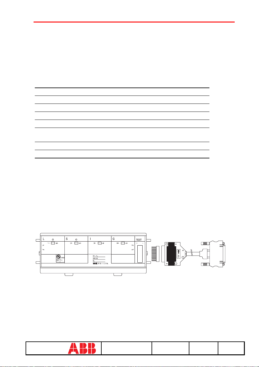
7.3 Indications on operation
In=
InN=In/2
Nr.
+ -
LISTED
Low-VoltageAC
PowerCircuit-Breaker
TripUnit
63TA
I1=
xIn
I2=
xIn
I3=
xIn
I4=
xIn
I GL
S
RP 11 1
TEST
TO
P
/ P-A
In the case of testing with the SACE PR010/T unit for G protection function, the maximum trip
time tolerance value is 35%. The minimum threshold is 0.6 x In for the manual test.
Example of an automatic test application on the PR111/LSI unit fitted on CB E1B12, with CT
= 800 A, Neutral = 50%.
1. From the main menu select 1 (Operation mode)
2. Select the PR111 unit with 1
3. Select the version of the PR111 with 2
4. Enter 1 to select the Neutral setting
5. Enter 2 to select the type of CB
6. Select the current rating of the CTs fit-
(PR111)
(PR111-LSI)
(Neutral = 50%)
(E1B12)
(800 A)
ted with 3
7. Select the type of test with 1
8. Select the test mode with 1
(Protections)
(Automatic)
[Make sure the default setting is programmed for automatic testing as shown under the heading
"Default setting for automatic PR111/P testing"].
8. SACE PR111/P-A protection release
ABB SACE SACE PR010/T RH0029002 L2551 22/67
67
Page 24
8.1 Default setting for automatic PR111/P-A testing
To test the protection functions in automatic mode, first set the PR111/P-A protection unit as
follows:
Protection
Threshold Curve
function
L 0.4 x In B
S 3 x In
I 8 x In -
G 0.4 x In B
C; I
2
t=k
8.2 Operation mode menu tree
1° 2° 3° 4° 5° 6° 7°
1. Operation
mode
4. Select DUT
(PR111-A)
1. Protections 1. Automatic Start test
2. I inst
protection
2. Manual Set
Start test
parameters
Start test
Create
8.3 Indications on operation
In the case of testing with the SACE PR010/T unit for G protection function, the maximum trip
time tolerance value is 35%.
Automatic test example for unit PR111/P-A LSI mounted on CB E1B12, with CT = 800 A,
Neutral = 50%.
1. From the main menu select 1 (Operation mode)
2. Select the PR111-A unit with 4 (PR111-A)
3. Select the version of the PR111-A with 2 (PR111-A/LSI)
4. Enter 1 to select the Neutral setting (Neutral = 50%)
5. Enter 2 to select the type of CB (E1B12)
6. Select the current rating of the CTs fitted
with 3
7. Select the type of test with 1 (Protections)
8. Select the test mode with 1 (Automatic)
(800 A)
report
[Make sure the default setting is programmed for automatic testing as shown under the heading
"Default setting for automatic PR111/P-A testing"].
ABB SACE SACE PR010/T RH0029002 L2551 23/67
67
Page 25
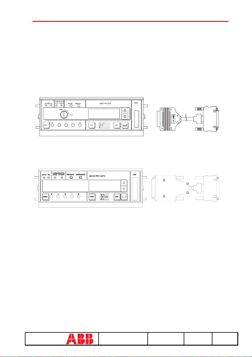
9. PR112/P and SACE PR112/PD
InN= In/2
SACE PR112/PD
RESET
O L
S I
G
TEST
Nr.=
In=
upFault
READ
COMMUNICATION
Vaux
upFault
NETWORK
EDIT
EMERGENCYWARNING
ESC
TEST
TO
P
protection release
9.1 Version with key (last letter in serial number A ÷ D)
9.2 Version without key (last letter in serial number M ÷ Z)
ABB SACE SACE PR010/T RH0029002 L2551 24/67
67
Page 26

9.3 Operation mode menu tree
1° 2° 3° 4° 5° 6° 7° 8° 9° 10°
1. Operation mode
2. Select DUT (PR112)
1. Select DUT (PR112A:D)
1.Protections 1.Automatic Star t test Create
2. Manual
1. Test
2. I inst protection Start test
3. Trip Star t test
1. Ammeter Read currents
2. Config./Param. 1. DUT config. Display DUT configuration
2. DUT
parameters
3. Default
parameters
2. Reading
2. Select DUT (PR112M:Z)
3. Information Read release identification, SW version and Serial
1. Change DUT
parameters
2. Default
parameters
3. Define default
parameters
3. Programming
Number
1. DUT config. Change DUT configuration parameters
2. DUT
parameters
Program DUT with default parameters for normal
operation
1. Only for test 1. DUT config. Def. DUT configuration
2. Operative
1. Default
setting
2. User
setting
Display DUT parameters
1.Only for test 1. DUT
2.Operative 1. DUT
Change DUT protection parameters
2. DUT
parameters
1. DUT config. Def. DUT configuration
2. DUT
parameters
Start test
Set
parameters
config.
2. DUT
parameters
config.
2. DUT
parameters
Def. DUT parameters
Def. DUT parameters
Start test
Display DUT
default
config.
Display DUT
default
param.
Display DUT
default
config.
Display DUT
default
param.
report
ABB SACE SACE PR010/T RH0029002 L2551 25/67
67
Page 27

9.4 Indications on operation
• The SACE PR010/T test unit can be used:
- in all SACE PR112/P and SACE PR112/PD protection releases in the version "without key".
- in all SACE PR112/P and SACE PR112/PD protection releases, in the version "with key",
having Sw version 2.20 or later and serial number later than No. xxxxx03x (for PR112/P) or No.
xxxxx05x (for PR112/PD).
NOTE: The PR112 software release can be read on the display by choosing in
sequence:
• Config/Program.
• Information
• The SACE PR112/PD releases must be connected to the auxiliary power supply for use with
the SACE PR010/T unit.
Remarks for PR112 in version "with key"
• G protection function test:
• If working in automatic mode, the threshold current must be set to a value higher than or
equal to 0.4xIn (if it is set at a lower value the PR010/T unit will reset it at 0.4xIn during the
test phase). The test current is equal to 2.5 times the threshold current.
• In the case of manual mode the test current is 1.5xIn.
• It is possible that after a test (with trip) on G protection function other trips of the protection
will occur during the next 2s.
• Contact wear for PR112:
• During testing on the PR112, with timing before trip higher than 10s, there could be an
increase in the indications contact wear and number of operations. After some tests wear could
reach 100% of the value, resulting in the appearance of the EMERGENCY message. This
indication can be reset by the customer by means of the following procedure:
• Choose in READ mode the page of the contact wear indication
• Choose EDIT mode by turning the key
• Hold down the "Up" and "Down" buttons simultaneously for at least 5 seconds.
• In this way the contact wear and number of operations indications will be reset to zero.
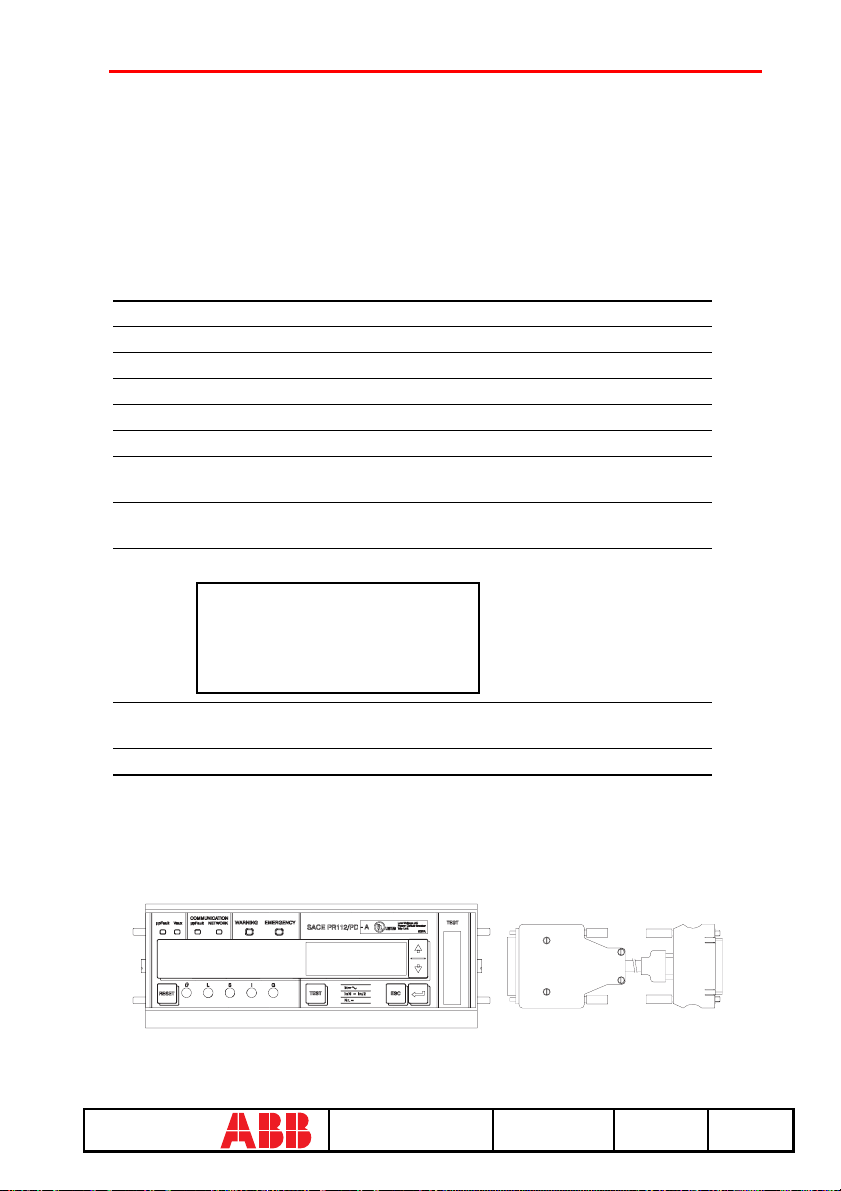
WARNING
Connect the test wire provided (between the SACE PR010/T and the SACE
PR112) the right way round (see the adhesive labels on the connectors).
ABB SACE SACE PR010/T RH0029002 L2551 26/67
67
Page 28
Manual test example for release PR112/P (vers. "without key").
NOTE: the data indicating the type of CB and protection, the rated current of the
CTs and the Neutral setting are automatically identified by the PR010/T test unit.
In this example, protection function "I" is tested with curve t=k, threshold I3=1.5*In, supplying a
fault current equivalent to 2 times the rated current (In).
1. From the main menu select 1 (Operation mode)
2. Select the PR112 unit with x (PR112)
3. Select the M÷Z version 2 (PR112) (M÷Z)
4. Select the type of activity with 1 (Test)
5. Select the type of test 1 (Protections)
6. Select the test mode 2 (Manual)
7. Select the type of setting used to test
the protections
8. Select the protection function to be
tested
9. Using the arrow keys, fill in the page displayed as follows:
2 (User setting)
3 (I protection test)
I-PROT: t=k, ON
I3: 1.5In => 3000°
t3: Instantaneous
I-f: 2.00In => 4000 A(*)
10. Select the phase (or phases) on which to simulate the fault current
(L1+L2+L3)
11. Press ENTER to activate fault simulation
(*) In this example, the
automatically identified
rating of the current
sensor is 2000 A.
10.
PR112/P-A and SACE PR112/PD-A protection release
ABB SACE SACE PR010/T RH0029002 L2551 27/67
67
Page 29
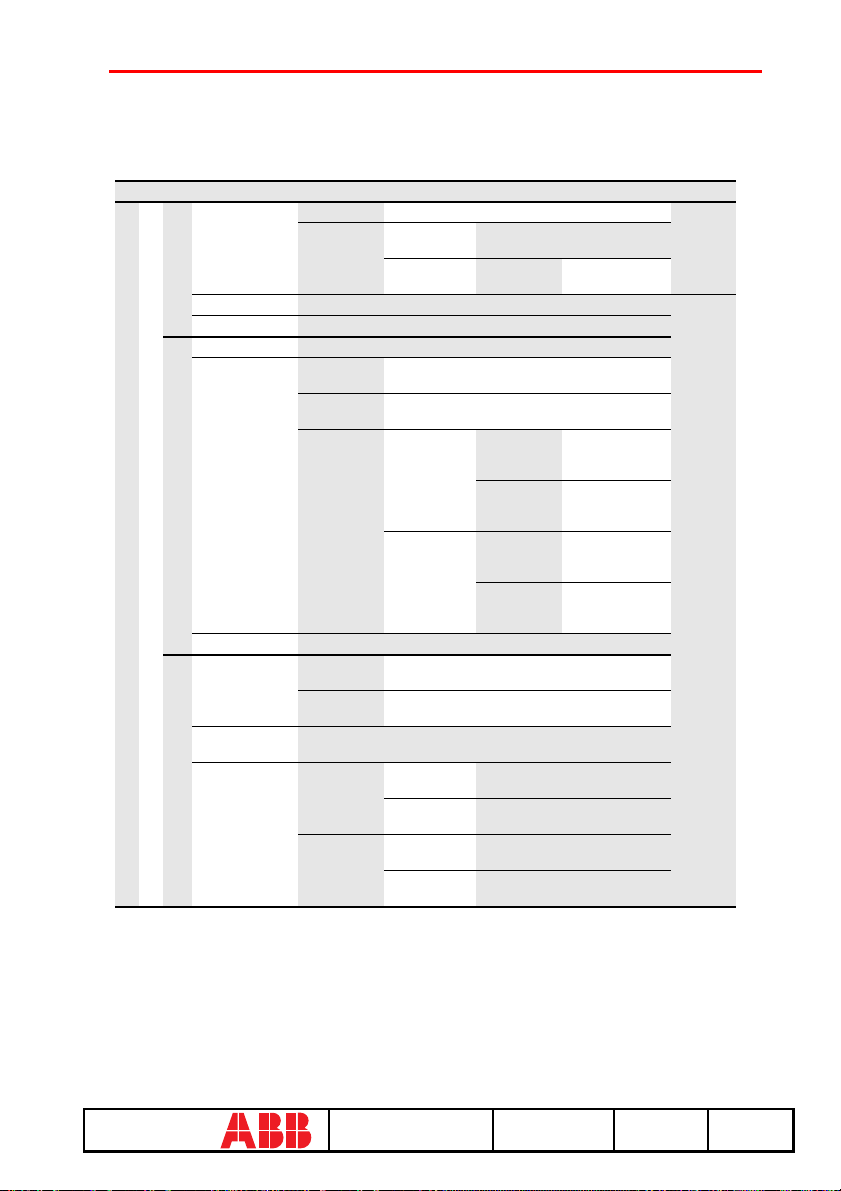
10.1 Operation mode menu tree
1° 2° 3° 4° 5° 6° 7° 8° 9°
1.Protections 1.Automatic Start test (select SET ELT) Create
1. Operation mode
1. Test
2. I inst protection
3. Trip Start test
1. Ammeter Read currents
2. Config./Param.
2. Reading
2. Select DUT (PR112-A)
3. Information
1. Change DUT
parameters
2. Default
parameters
3. Define default
parameters
3. Programming
2. Manual 1. Default
Start test
1. DUT
configur.
2. DUT
parameters
3. Default
parameters
Read release identification, SW version and Serial Number
1. DUT
configur.
2. DUT
parameters
Program DUT with default parameters for normal operation
1. Only for
test
2. Operative 1. DUT
setting
2. User setting
Display DUT configuration
Display DUT protection parameters
1. Only for test 1. DUT
2. Operative
Change DUT configuration parameters
Change DUT configuration parameters
1. DUT
configur.
2. DUT
parameters
configur.
2. DUT
parameters
Start test
Set
parameters
configur.
2. DUT
protection
parameters
1. DUT
configur.
2. DUT
protection
parameters
Define DUT configuration
parameters
Define DUT protection
parameters
Define DUT configuration
parameters
Define DUT protection
parameters
Start test
Display DUT
default
configuration
Display DUT
default
parameters
Display DUT
default
configuration
Display DUT
default
parameters
report
ABB SACE SACE PR010/T RH0029002 L2551 28/67
67
Page 30
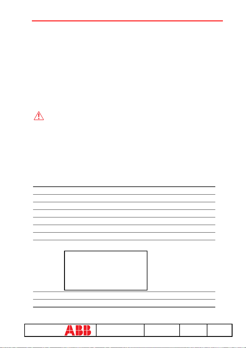
10.2 Indications on operation
• The SACE PR010/T unit can be used with all PR112/P-A and PR112/ PD-A protection
releases.
• The SACE PR112/PD-A releases must be connected to the auxiliary power supply for use
with the SACE PR010/T unit.
NOTE: The PR112/P-A software release can be read on the display by choosing
in sequence in READ mode, starting from the main menu:
- Config./Program
- Information
WARNING
Connect the test wire provided (between the SACE PR010/T and the SACE
PR112) the right way round (see the adhesive labels on the connectors).
Manual test example for release PR112/P-A.
NOTE: the data indicating the type of CB and protection, the rated current of the
CTs and the Neutral setting are automatically identified by the PR010/T test unit.
In this example, protection function "S" is tested with curve t=k, threshold I2=1.20*In, curve
t2=0.4 s supplying a fault current equivalent to 2 times the rated current (In).
1. From the main menu select 1 (Operation mode)
2. Select the PR112-A unit with x (PR112-A)
3. Select the type of activity with 1 (Test)
4. Select the type of test with 1 (Protections)
5. Select the test mode with 2 (Manual)
6. Select the type of setting used to test the protections with
7. Select the protection function you want to test with 2 (S protection test)
8. Using the arrow keys, fill in the page displayed as
follows:
S-PROT: t=k, ON
S protection test: t=k
L2: 1.2In => 2400 A
T2: 0.4 s
I-f: 2.00 => 4000 A(*)
2 (User setting)
(*) In this example, the
automatically identified
rating of the current
sensor is 2000 A. Check
that I-F is lower than I3.
9. Select the phase (or phases) on which to simulate the fault current (L1+L2+L3)
10.Press ENTER to activate fault simulation.
ABB SACE SACE PR010/T RH0029002 L2551 29/67
67
Page 31
11. SACE PR113/P and PR113/PD protection release
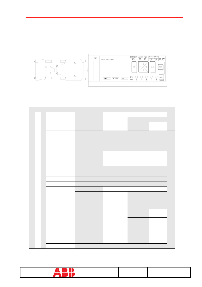
11.1 Operation mode menu tree
1° 2° 3° 4° 5° 6° 7° 8° 9°
1. Protections 1. Automatic Start test
2. Manual 1. Default setting Start test
1. Test
2. I inst protection
3. Trip Start test
1. Currents Read currents
2. Voltages
2. Powers
4. Energy counters
5. Power factors
6. Freq./peak factor
7. Last trip
8. Config./Param.
1. Operation mode
2. Select DUT (PR113)
2. Reading
9. Information
2. User setting
Start test
Read voltages
1. Active Power Read active power
2. Reactive power Read reactive power
3. Apparent power Read apparent power
Read energy counters
Read power factors
Read Freq./peak factor
Read last trip
1. DUT configur. Display DUT configuration
2. DUT parameters 1. Protection
3. Default
parameters
Read release identification, SW version and Serial Number
parameters
2. Other
parameters
1. For test 1. DUT
2 Operative
Set
parameters
Read protection parameters
Read other parameters
configur.
2. DUT
parameters
1. DUT
configur.
2. DUT
parameters
Start test
Read
config.
Read
param.
Read
config.
Read
param.
Create
report
ABB SACE SACE PR010/T RH0029002 L2551 30/67
67
Page 32
1° 2° 3° 4° 5° 6° 7° 8° 9°
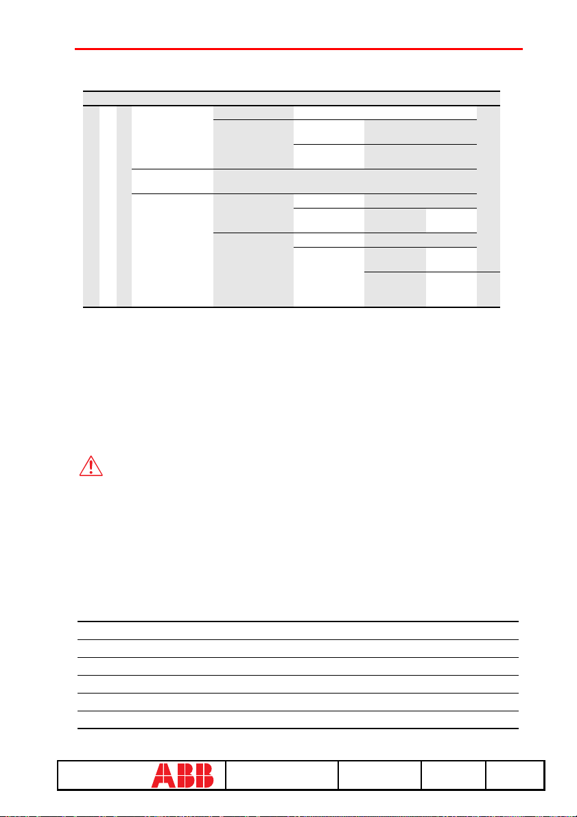
1. Operation mode
2. Select DUT (PR113)
1. Change DUT
config./
parameters
2. Download def.
parameters
3. Def. parameters
in PR010/T
3. Programming
1. DUT config. Change DUT configuration parameters
2. DUT param. 1. Protection
Download
1. For test 1. DUT config. Change DUT configuration
2. Operative 1. DUT config. Change DUT configuration
parameters
2. Other
parameters
2. DUT param.
2. DUT param.
Change DUT protection
parameters
Change other parameters
1. Protection
parameters
1. Protection
parameters
2. Other
parameters
Change
protect. par.
Change
parameters
Change
other
parameters
11.2 Indications on operation
• The SACE PR010/T unit can be used with all SACE PR113/P and SACE PR113/PD protection releases.
• The SACE PR113/PD releases must be connected to the auxiliary power supply for use with
the SACE PR010/T unit.
• The tests must be carried out with the circuit breaker off, no voltage to the busbar (V=0)
(where the VTs are installed to measure the SACE PR113/P and SACE PR113/PD release
voltage) and the auxiliary power supply enabled.
WARNING
Connect the test wire provided (between the SACE PR010/T and the SACE
PR113) the right way round (see the adhesive labels on the connectors).
Example of an automatic test application on the PR113 release.
NOTE: the data on the CB and protection, on the current rating of the CTs and
on the neutral setting are automatically identified by the PR010/T.
In this example, all the protection functions implemented by the SACE PR113/P and SACE
PR113/PD release are tested automatically:
1. From the main menu select 1 (Operation mode)
2. Select the PR113 unit with x (PR113)
3. Select the type of activity with 1 (Test)
4. Select the type of test with 1 (Protections)
5. Select the test mode with 1 (Automatic)
6. Pressing ENTER enables a simulation of the failure for each protection function.
ABB SACE SACE PR010/T RH0029002 L2551 31/67
67
Page 33
12.
SACE PR113/P-A and PR113/PD-A protection release
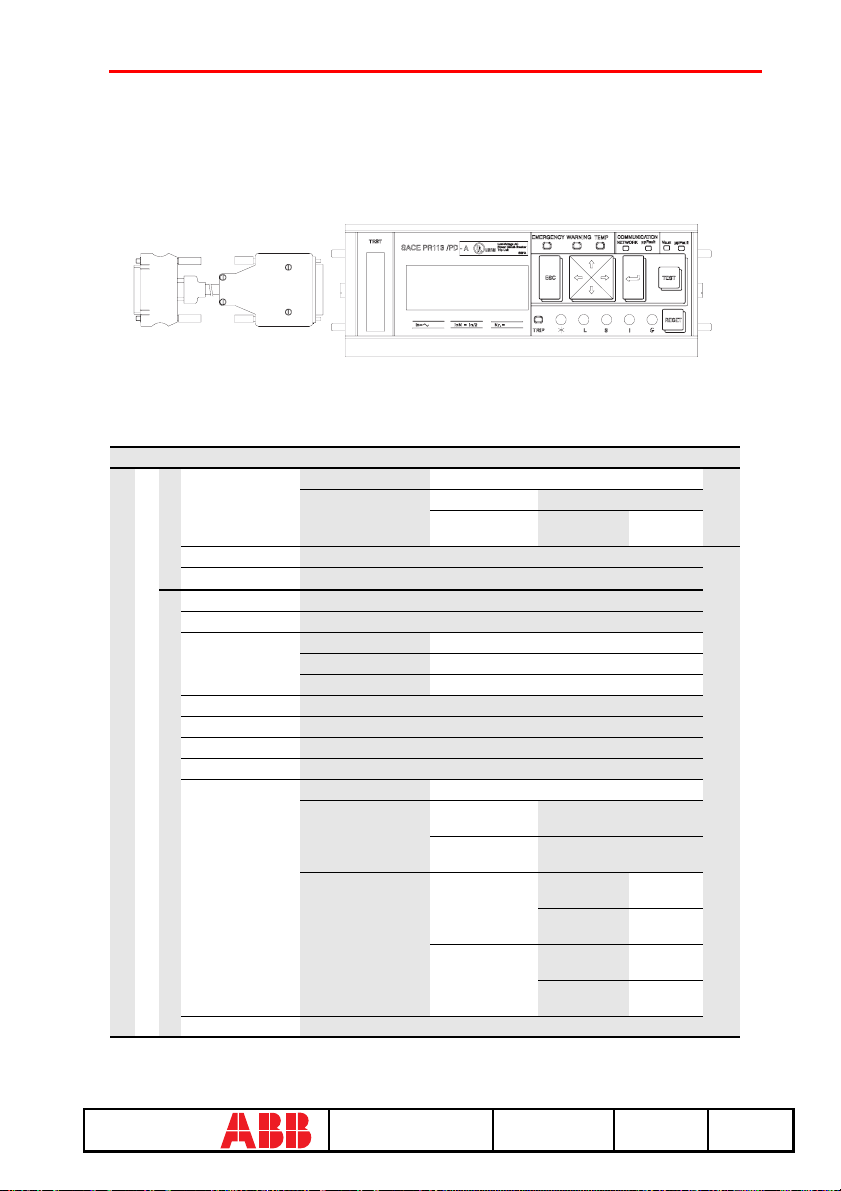
12.1 Operation mode menu tree
1° 2° 3° 4° 5° 6° 7° 8° 9°
1.Protections 1.Automatic Start test
2. Manual 1. Default setting Star t test
1. Test
2. I inst protection
3. Trip Start test
1. Currents Read currents
2. Voltages
3. Powers
4. Energy counters
5. Power factors
6. Freq./peak factor
7. Last trip
8. Configuration/
2. Select DUT (PR113-A)
2. Reading
param.
9. Information
1. Operation mode
2. User setting
Start test
Read voltages
1. Active Power Read active power
2. Reactive power Read reactive power
3. Apparent power Read apparent power
Read energy counters
Read power factors
Read Freq./peak factor
Read last trip
1. DUT configur. Display DUT configuration
2. DUT parameters 1.Protection
3. Default parameters 1. For test 1. DUT config. Read
Read release identification, SW version and Serial Number
parameters
2. Other
parameters
2 Operative
Set
parameters
Read protection parameters
Read other parameters
2. DUT param. Read
1. DUT config. Read
2. DUT param. Read
Start test
config.
param.
config.
param.
Create
report
ABB SACE SACE PR010/T RH0029002 L2551 32/67
67
Page 34
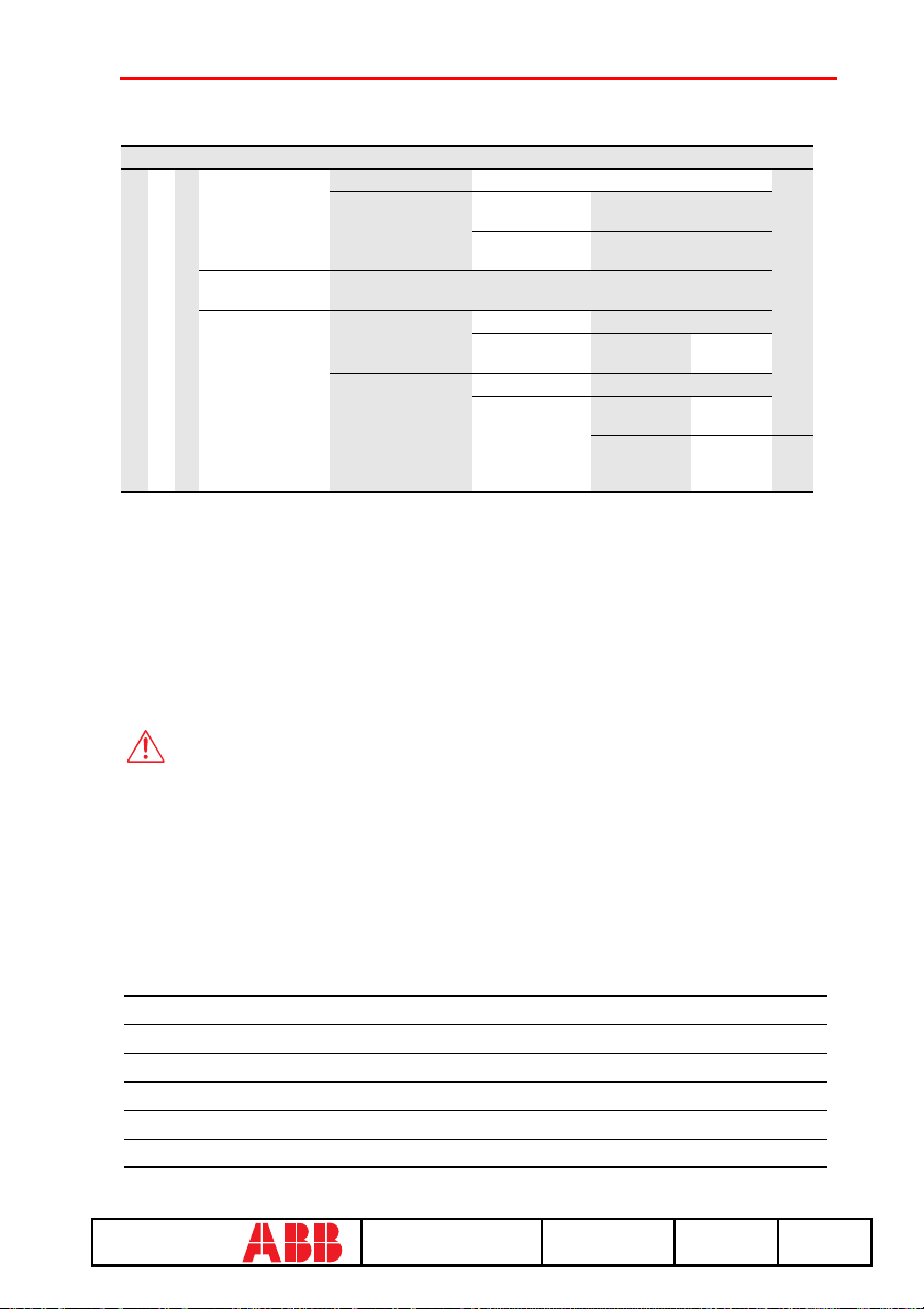
1° 2° 3° 4° 5° 6° 7° 8° 9°
1. Operation mode
2. Select DUT (PR113-A)
1. Change DUT
config./
parameters
2. Download def.
parameters
3. Def. parameters
in PR010/T
3. Programming
1. DUT config. Change DUT configuration parameters
2. DUT param. 1. Protection
Download
1. For test 1. DUT config. Change DUT configuration
2. Operative 1. DUT config. Change DUT configuration
parameters
2. Other
parameters
2. DUT param.
2. DUT param.
Change DUT protection
parameters
Change other parameters
1. Protection
parameters
1. Protection
parameters
2. Other
parameters
Change
protect. par.
Change
parameters
Change
other
parameters
12.2 Indications on operation
• The SACE PR010/T unit can be used with all SACE PR113/P-A and SACE PR113/PD-A protection releases.
• The SACE PR113/PD-A releases must be connected to the auxiliary power supply for use
with the SACE PR010/T unit.
• The tests must be carried out with the circuit breaker off, no voltage to the busbar (V=0)
(where the VTs are installed to measure the SACE PR113/P-A and SACE PR113/PD-A
release voltage) and the auxiliary power supply enabled.
WARNING
Connect the test wire provided (between the SACE PR010/T and the SACE
PR113) the right way round (see the adhesive labels on the connectors).
Example of an automatic test application on the PR113 release
NOTE: the data on the CB and protection, on the current rating of the CTs and
on the neutral setting are automatically identified by the PR010/T.
In this example, all the protection functions implemented by the SACE SACE PR113/P-A and
SACE PR113/PD-A release are tested automatically:
1. From the main menu select 1 (Operation mode)
2. Select the PR113 unit with x (PR113 A)
3. Select the type of activity with 1 (Test)
4. Select the type of test with 1 (Protections)
5. Select the test mode with 1 (Automatic)
6. Pressing ENTER enables a simulation of the failure for each protection function
ABB SACE SACE PR010/T RH0029002 L2551 33/67
67
Page 35
13.SACE PR121/P protection release
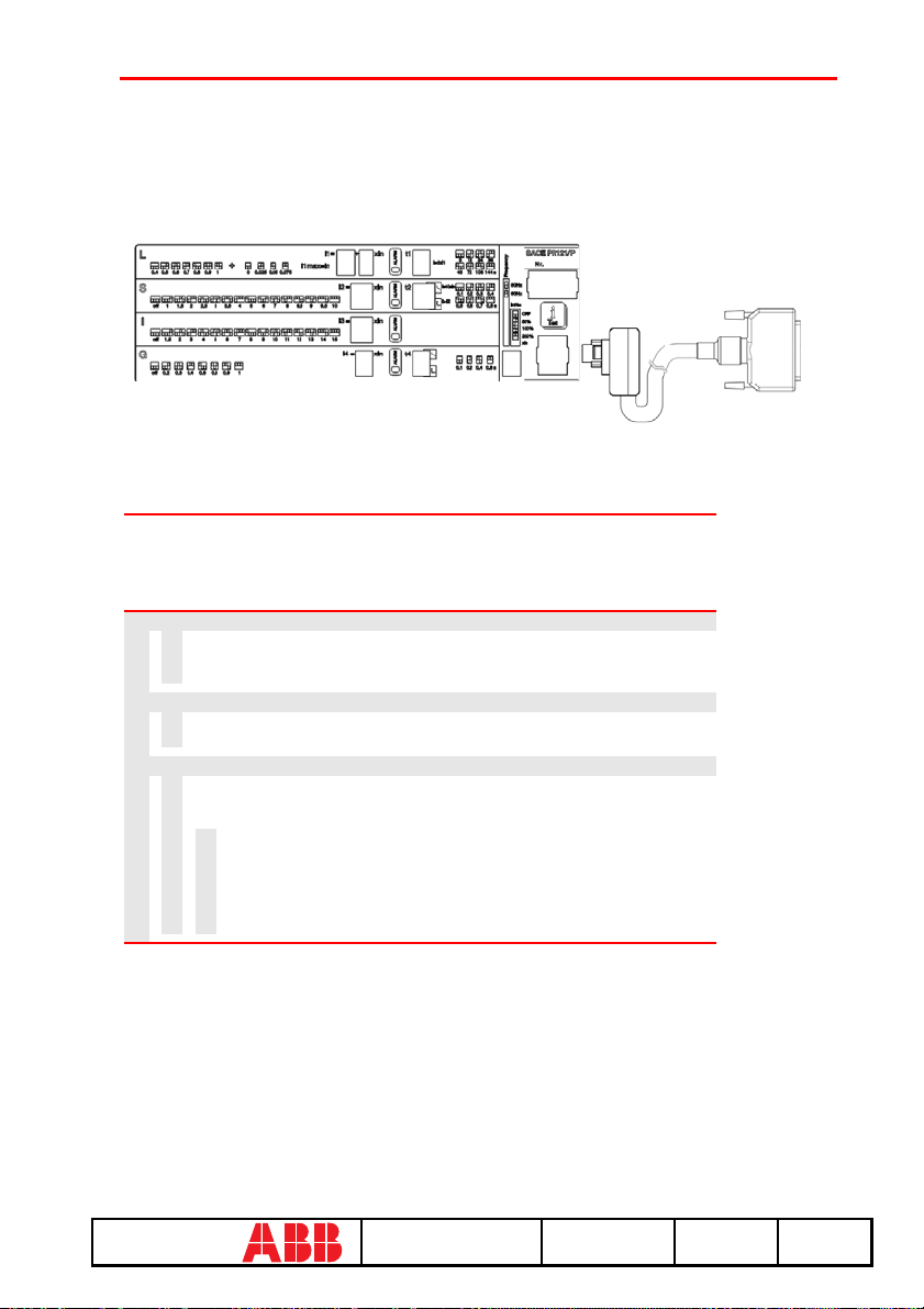
13.1 Operation mode menu tree
PR121 UNIT
1. Test
1.
Start automatic test Test report
2.
Start manual test Test report
3.
Start trip test
2. Measurements
1.
Display currents
2.
Display peak factors
3. History
1.
Trip History display
2.
Events display
3.
Statistics
1.
Display contact wear
2.
Display total no. prot. trips
3.
Display no. manual oper.
4.
Display no. prot. oper.
5.
Display no. trip failures
6.
Display no. trip tests
1. Test
2. Measurements
3. History
4. Config/Param
5. Information
6. Status
ABB SACE SACE PR010/T RH0029002 L2551 34/67
67
Page 36
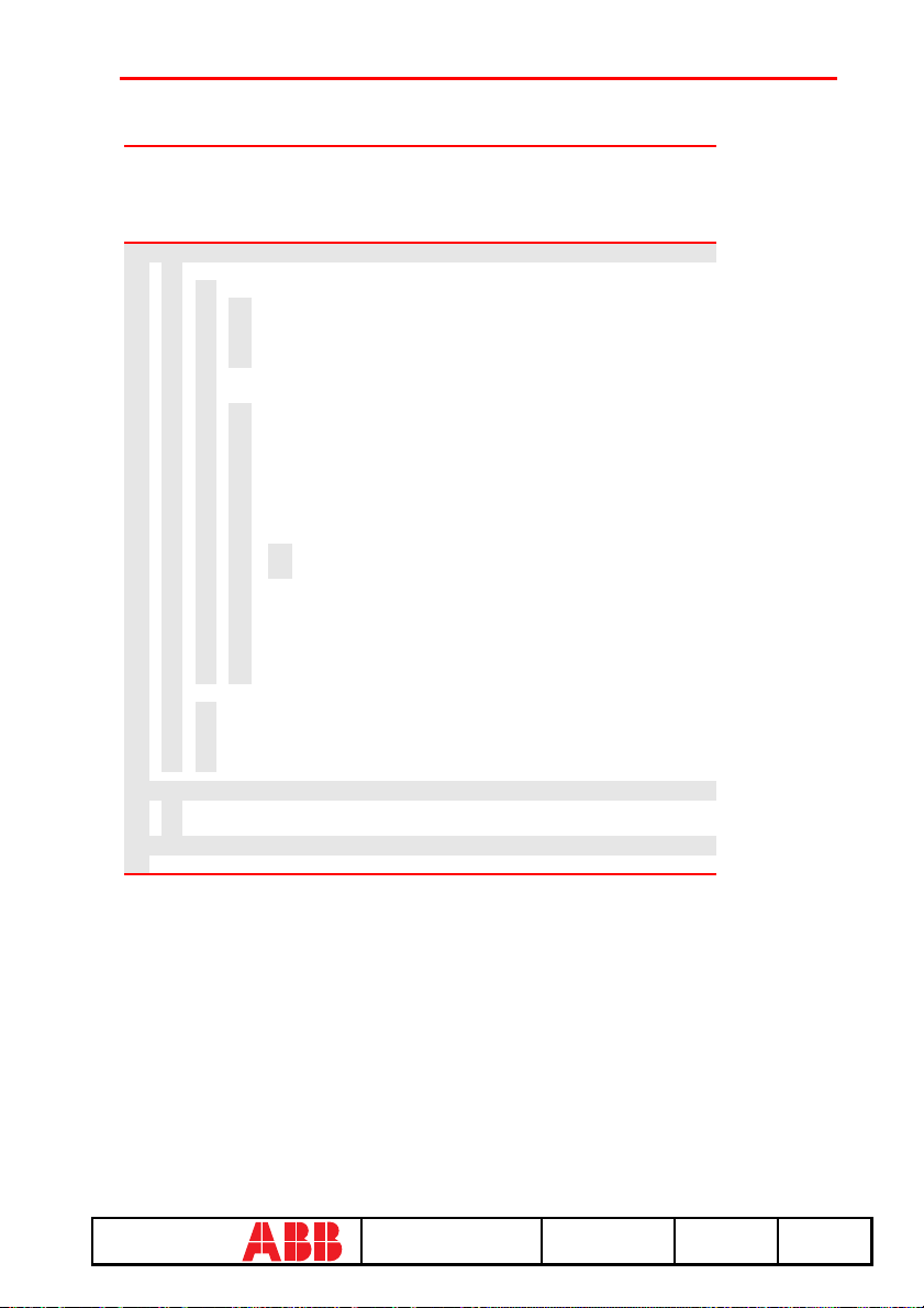
PR121 UNIT
4. Config/Param
1.
Configurations
1.
Circuit breaker
1.
2.
3.
4.
2.
Display mains frequency
3.
Local bus unit
1.
2.
3.
4.
5.
6.
7.
8.
3.
4.
5.
6.
7.
2.
5. Information
1.
2.
6. Status
1. Display configuration error
8.
Protection parameters
1.
Protection L parameters
2.
Protection S parameters
3.
Protection I parameters
4.
Protection G parameters
Protection unit information
Circuit breaker information
1. Test
2. Measurements
3. History
4. Config/Param
5. Information
6. Status
Display neutral protection
Display plant config.
Display CB TAG Name
Display User Data
Local bus unit presence
Release 1 configuration
Release 2 configuration
Release 3 configuration
Release 4 configuration
Release 6 configuration
Release 7 configuration
Release 8 configuration
1.
Type of signal source Display custom. type
2.
Display source configuration
Release 2 configuration
Release 3 configuration
Release 4 configuration
Release 6 configuration
Release 7 configuration
Release 8 configuration
13.2 Indications on operation
• The SACE PR010/T test unit can be used with all SACE PR121/P releases by connecting the
test unit to the protection unit with the cable provided, to be inserted in the test connector on
the front.
• It is not necessary for the auxiliary supply to be present in order to use the above releases with
the PR010/T unit.
• The automatic and manual tests must be performed with the circuit breaker off while the trip
test may be performed only with the circuit breaker on; in either case the circulating currents
must be null.
ABB SACE SACE PR010/T RH0029002 L2551 35/67
67
Page 37
WARNING
For PR121/P releases with a version prior to 1.0, the following limitations
must be considered:
1. Startup time protection S:
0.1 ≤ Time ≤ 1.5 s step 0.01 s
2. Startup time protection S2: 0.1 ≤ Time ≤ 1.5 s step 0.01 s
3. Startup time protection G: 0.1 ≤ Time ≤ 1.5 s step 0.01 s
4. Startup time protection Gext: 0.1 ≤ Time ≤ 1.5 s step 0.01 s
5. Startup time protection D: 0.1 ≤ Time ≤ 1.5 s step 0.01 s
6. Startup current activation threshold not contemplated
7. Protection U threshold: 5% ≤ th ≤ 90% step 5%
8. Management of unit contacts on local bus not contemplated.
A description of the various menus is given below.
13.3 Test
By means of the PR010/T unit it is possible to perform some tests on the protection unit, in
particular:
1. Automatic test
2. Manual test
3. Trip test
For example, to perform the automatic test it is necessary to follow the procedure described in the
following table:
Key to be pressed Item selected
1 Operation mode
x PR121/P
1Test
1 Automatic test
ENTER
A brief description of the various tests will be given below.
ABB SACE SACE PR010/T RH0029002 L2551 36/67
67
Page 38

13.3.1 Automatic test of the release PR121/P
With the automatic test, a sequence of 7 different tests will be performed at the currents and
phases indicated in the following table.
Test N° Phase Value
L1 L2 L3
1
2
3
4
5
6
7
uuu
uuu
uuu
uuu
uuu
u
u
10.0 In
15.0 In
0.3 In
3.0 In
5.0 In
0.3 In
3.0 In
The trip times of the release in the various tests will depend on the settings of the protections; on
the display the PR010/T unit will show the trip time and the result of the test (OK;FAILED).
At the end of the test it is asked whether to record a test report which may later be downloaded on
a PC.
13.3.2 Manual Test
The manual test allows testing of the release trip time with the desired load condition, in
particular it offers the possibility of selecting the current value in a range between 0.00 and 16.00
In and of selecting the phases involved in the test (L1, L2, L3, Ne, Gext).
The release trip time will depend on the settings of the protections; on the display the PR010/T
unit will show the trip time and the result of the test (OK, FAILED).
At the end of the test it is asked whether to record a test report which may later be downloaded on
a PC.
13.3.3 Trip test
With this test it is possible to send a command to turn off the circuit breaker, thus checking the
functionality of the protection opening system.
The trip test command is accepted by the protection unit only if the circuit breaker is on.
ABB SACE SACE PR010/T RH0029002 L2551 37/67
67
Page 39

13.4 Measurements
It is possible to display the measures of the circulating currents and of the peak factors.
For example to display the current measurements, the following selections must be made:
Key to be pressed Item selected
1 Operation mode
x PR121/P
2 Measurements
1 Currents
ENTER
13.5 History
Under the history menu is the display of the history for the openings of the protection tripped, the
events and some statistical information on the openings of the release.
For example to display the history of the openings (trip history), the following selections must be
made:
Key to be pressed Item selected
1 Operation mode
x PR121/P
3 History
1 Trip history
ENTER
ABB SACE SACE PR010/T RH0029002 L2551 38/67
67
Page 40
13.6 Configurations/parameters
It is possible to display and even modify the configurations and parameters of the release.
13.6.1 Configurations
The available configuration parameters are divided into the following sub-sets:
1. Circuit breaker
2. Mains frequency
3. Local bus unit
For example, starting from the main menu, selecting:
Key to be pressed Item selected
1 Operation mode
x PR121/P
4 Config./Parameters
1 Configurations
1 Circuit breaker
1 Neutral protection
ENTER
enters the screen that displays the configuration parameters of the neutral protection and the
following screen appears:
Neutral protection
Enable: ON[OFF]
Threshold: 50 [...]%
Pressing the ENTER key launches editing mode (the cursor starts blinking); the bu ttons and
are used to position the cursor on the desired parameter and the buttons and to change the
value of the parameters in the allowed range.
ABB SACE SACE PR010/T RH0029002 L2551 39/67
67
Page 41
13.6.1.1 Local bus unit
From the CONFIGURATIONS menu it is possible to set the parameters for operation of the
release unit on the local bus, selecting:
Key to be pressed Item selected
1 Operation mode
x PR121/P
4 Config./Parameters
1 Configurations
3 Circuit breaker
... Local bus unit
At this point it is possible to choose one of the following items:
1. Presence
2. Release 1
3. Release 2
4. Release 3
5. Release 4
6. Release 6
7. Release 7
8. Release 8
Selecting "Presence" sets the presence/absence of a unit on the local bus.
Selecting Release x the configuration parameters of release x on the local bus unit are read/set, for
example selecting:
Key to be pressed Item selected
... ...
4 Release 3
1 Source
The setting of the activation signal of release no. 3 is displayed; pressing the ENTER key
launches editing mode (the cursor starts blinking); the setting of the activation signal is changed
using the keys and .
If "Custom" is selected, when ENTER is pressed the current setting is displayed, for example:
ALARM 1 4...6
→ L Pre-alarm
L Timing
→ S Timing
ABB SACE SACE PR010/T RH0029002 L2551 40/67
67
Page 42
Where the arrows indicate which elements of the ALARM 1 block are selected.
The buttons and are used to display the previous/next screen and the buttons and to
activate/deactivate the selected element (the arrow next to the element is shown/removed)
There are 18 blocks, each of which is made up of eight elements and is displayed in three
consecutive screens; up to 8 elements may be activated for each block.
On the last screen of each block it is possible to define the AND/OR logic applied to the selected
elements and the minimum release activation time.
13.6.2 Parameters
The protection parameters are divided into:
1. L protection
2. S protection
3. I protection
4. G protection
For example, selecting:
Key to be pressed Item selected
1 Operation mode
x PR121/P
4 Config./Parameters
2 Parameters
1 Protection L
ENTER
enters the screen that displays the parameters of protection L and the following screen appears:
L prot t=k/i2 [...]
Threshold: x.xx In
Time: x.xx s
Thermal mem: ON [OFF]
Pressing the ENTER key launches editing mode (the cursor starts blinking); the bu ttons and
are used to position the cursor on the desired parameter and the buttons and to change the
value of the parameters in the allowed range.
ABB SACE SACE PR010/T RH0029002 L2551 41/67
67
Page 43
13.7 Information
On this menu it is possible to view some information on the protection unit and the circuit
breaker.
The menu is divided into:
1. Protection unit
2. Circuit breaker
For example, starting from the main menu, selecting:
Key to be pressed Item selected
1 Operation mode
x PR121/P
5 Information
2 Circuit breaker
ENTER
enters the screen that displays information on the circuit breaker:
Device: E1B800/4P
Rated Current: xxxxA
sn: xxxxxxxxxxxxxxx
Pressing the keys and passes to the display of the next/previous screen:
Install: xx/xx/xxxx
Maint: xx/xx/xxxx
13.8 Status
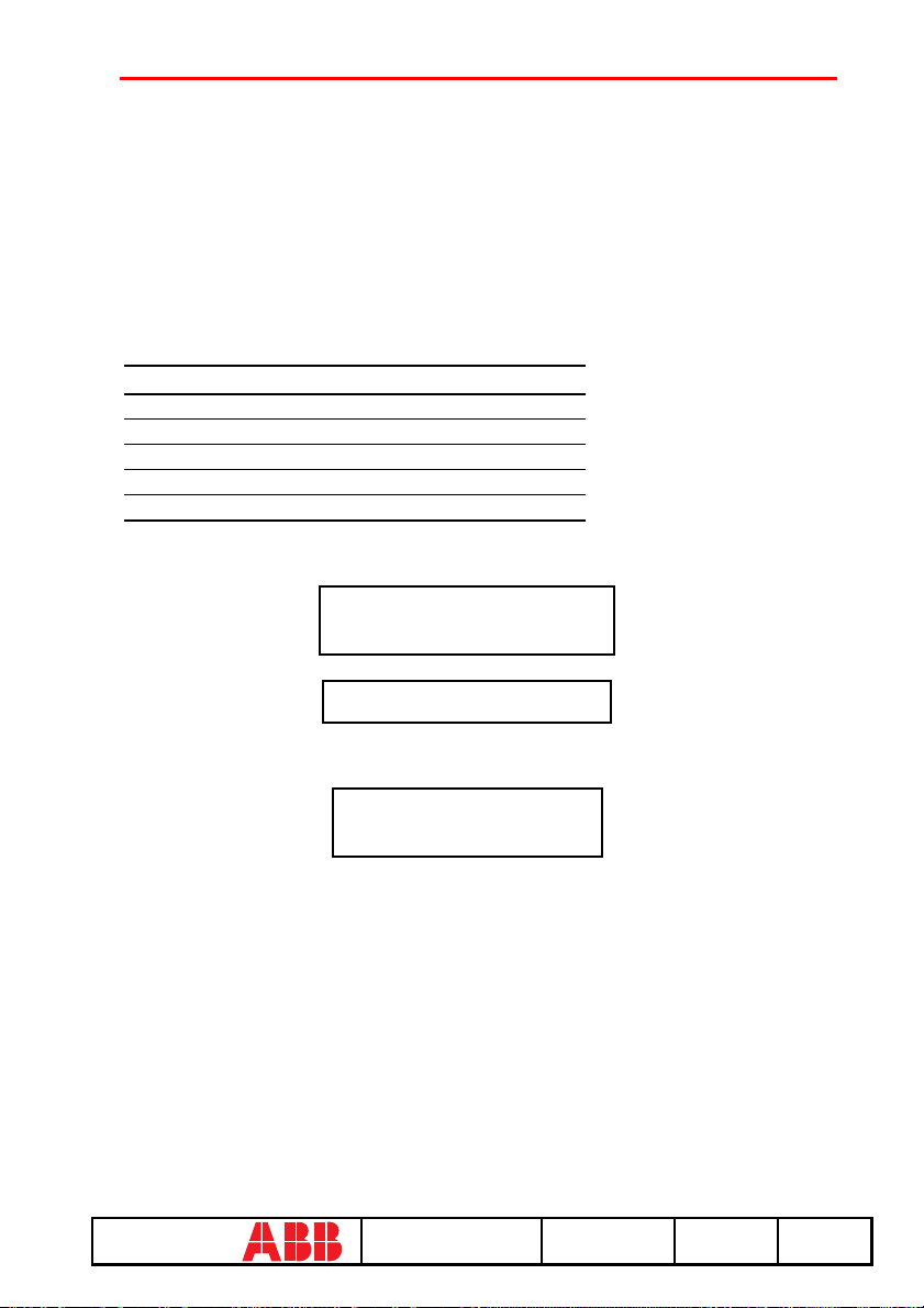
On this menu it is possible to view any signals of an error in configuration/wiring of the
protection unit and of the circuit breaker. In particular, one or more of the following messages
may be displayed:
1. No alarm
2. L Prealarm
3. T Prealarm
4. L1 Sensor error
5. L2 Sensor error
6. L3 Sensor error
7. Ne Sensor error
ABB SACE SACE PR010/T RH0029002 L2551 42/67
67
Page 44
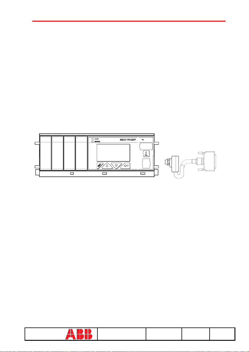
8. Gext sensor error
9. TC disconnected
10. Rating Plug error
11. Installation error
12. Device error
13. Invalid Date
14. Configuration error
15. CB status error
Refer to the release user manual for the solution of the errors indicated.
14.SACE PR122/P
protection release
ABB SACE SACE PR010/T RH0029002 L2551 43/67
67
Page 45
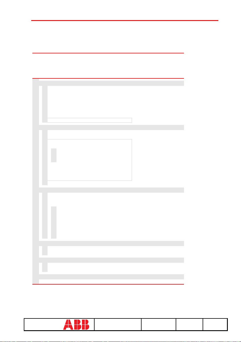
14.1 Operation mode menu tree
PR122 UNIT
1. Test
1.
Start automatic test Test report
2.
Start manual test Test report
3.
Start trip test
4.
Start signalling module autotest
5.
Force output S zone sel.
6.
Force output G zone sel.
7.
Release output zone sel.
8.
Start Rc test note 1
2. Measurements
1.
Display currents
2.
Display peak factors
3.
Display voltages
4.
POWERS
1.
2.
3.
5.
Display energies
6.
Display power factor
7.
Display measured frequency
8.
Reset energies counters
9.
Reset measurement history
3. History
1.
Display trip history
2.
Display events
3.
Statistics
1.
2.
3.
4.
5.
6.
7.
4. Config/Param
1.
CONFIGURATIONS >>
2.
PA R A M E TE R S > >
5. Information
1.
Protection unit information
2.
Circuit breaker information
1. Test
2. Measurements
3. History
4. Config/Param
5. Information
6. Status
Display active power
Display reactive power
Display apparent power
Display contact wear
Display total no. prot. trips
Display total no. prot. trips
Display no. manual operations
Display no. prot. operations
Display no. trip failures
Display no. trip tests
6. Status
1. Display configuration error
note 2
ABB SACE SACE PR010/T RH0029002 L2551 44/67
67
Page 46
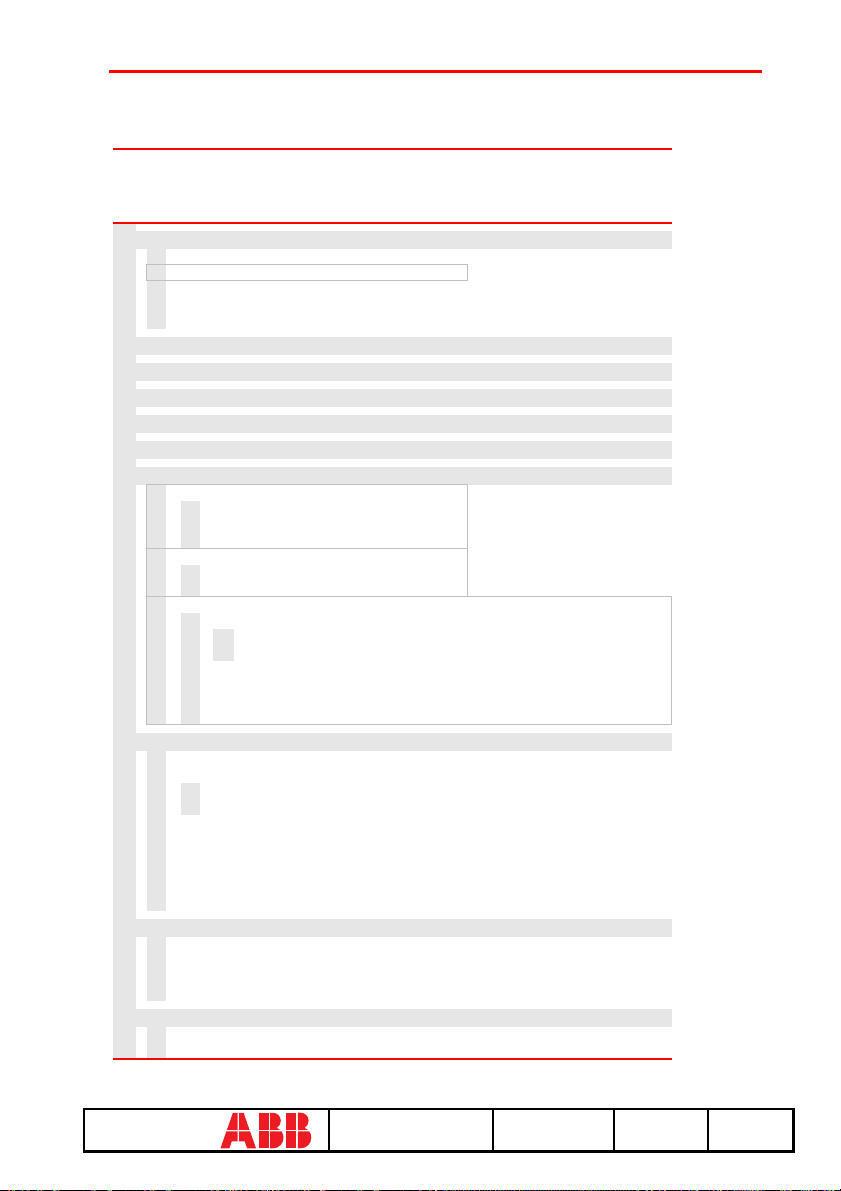
PR122 UNIT
CONFIGURATIONS
1. Circuit breaker
1.
Neutral protection parameters
2.
Ground toroide protection parameters note 1
3.
Plant config. parameters
4.
CB TAG Name
5.
User Data
1. Circuit breaker
2. Mains freq.
3. Meas. int.
4. Local bus an. Th.
5. Startup curr. Th.
2. Mains frequency
3. Measurement storage period
4. Local Bus analogue threshold
5. Startup current activation threshold
6. Enable/disable harmonic distortion alarm
7. Modules
1.
Measuring
1.
Voltage transformer parameters
2.
Neutral voltage presence
3.
Positive power direction
2.
Communication
1.
Operation mode
2.
Communication parameters
3.
Signalling module
1.
Release 1 configuration
1.
Type of signal source Display custom. type
2.
Display source configuration
2.
Release 2 configuration
3.
Release 3 configuration
4.
Release 4 configuration
5.
Input (signalling module configuration)
8. Local bus unit
1.
Local bus unit presence
2.
Release configuration
1.
Type of signal source Display custom. type
2.
Display source configuration
3.
Release 2 configuration
4.
Release 3 configuration
5.
Release 4 configuration
6.
Release 6 configuration
7.
Release 7 configuration
8.
Release 8 configuration
9. Data logger
1.
Data logger configuration
2.
Stop data logger event Display custom. type
3.
Reset data logger
4.
Stop data logger
10. System
1.
Display clock
2.
Set language
6. Harmonic distortion
7. Modules
8. Local bus unit
9. Data logger
10.System
note 2
note 3
note 4
ABB SACE SACE PR010/T RH0029002 L2551 45/67
67
Page 47

PR122 UNIT
Protection
parameters
1. Protection L parameters
2. Protection S parameters
3. Protection I parameters
4. Protection G parameters
5. Protection Ext G parameters
6. Protection U parameters
7. Protection T parameters
8. Protection LC1 parameters
9. Protection LC2 parameters
10. Protection Iw parameters
11. Protection Rc parameters
12. Protection MCR parameters
13. Protection UV parameters
14. Protection OV parameters
15. Protection RV parameters
16. Protection RP parameters
17. Protection UF parameters
18. Protection OF parameters
1. L prot.
2. S prot.
3. I prot.
4. G prot.
5. Ext G prot.
6. U prot.
7. T prot.
8. LC1 prot.
9. LC2 prot.
10. Iw prot.
11. Rc prot.
12. MCR prot.
13. UV prot.
14. OV prot.
15. RV prot.
16. RP prot.
17. UF prot.
18. OF prot.
note 5
note 6
note 6
note 1
note 2
note 2
note 2
note 2
note 2
note 2
NOTES
Only for performing LSIG (with measuring module) or LSIRc and presence of residual current
1
in the external toroide.
Only if measuring module present.
2
Only if communication module present.
3
Only if signalling module present.
4
Only for performing LSI or LSIG or LSIRc.
5
Only for performing LSIG.
6
14.2 Indications on operation
• The SACE PR010/T unit may be used with all SACE PR122/P releases connecting the test
unit to the protection unit by means of a special cable to the functional test connector.
ABB SACE SACE PR010/T RH0029002 L2551 46/67
67
Page 48
• It is not necessary for the auxiliary supply to be present in order to use the above releases with
the PR010/T unit.
• The automatic and manual tests must be performed with the circuit breaker off while the trip
test may be performed only with the circuit breaker on; in either case the circulating currents
must be null.
WARNING
For PR122/P releases with a software version prior to 1.0, the following
limitations must be considered:
1. Startup time protection S:
2. Startup time protection S2:
3. Startup time protection G:
4. Startup time protection Gext:
5. Startup time protection D:
0.1 s ≤ Time ≤ 1.5 s step 0.01 s
0.1 s ≤ Time ≤ 1.5 s step 0.01 s
0.1 s ≤ Time ≤ 1.5 s step 0.01 s
0.1 s ≤ Time ≤ 1.5 s step 0.01 s
0.1 s ≤ Time ≤ 1.5 s step 0.01 s
6. Startup current activation threshold not contemplated
7. Protection U threshold: 5% ≤ th ≤ 90% step 5%
8. Management of unit contacts on local bus not contemplated.
A description of the various menus is given below.
14.3 Test
By means of the PR010/T unit it is possible to perform some tests on the protection unit, in
particular:
1. Automatic test
2. Manual test
3. Trip test
4. Sign. mod. autotest
5. Force output S ZS
6. Force output G ZS
7. Release output ZS
8. Rc Test
For example, to perform the automatic test it is necessary to follow the procedure described in the
following table:
Key to be pressed Item selected
1 Operation mode
x PR122/P
1Test
1 Automatic test
ENTER
ABB SACE SACE PR010/T RH0029002 L2551 47/67
67
Page 49

A brief description of the various tests will be given below.
14.3.1 Automatic test of the release PR122/P
• In the absence of the PR120/V measuring module:
with the automatic test, a sequence of 7 different tests will be performed at the currents and phases
indicated in the following table:
Test N° Phase Value
L1 L2 L3
1
2
3
4
5
6
7
uuu
uuu
uuu
uuu
uuu
u
u
0.3 In
3.0 In
5.0 In
10.0 In
15.0 In
0.3 In
3.0 In
• In the presence of the PR120/V measuring module:
with the automatic test, a sequence of 13 different tests will be performed at the currents, voltages,
phase shift and phases indicated in the following table:
Test
N°
L1 L2 L3 V12 V23 V31 I [In] V[Un]
uu u u u u
1
uu u u u u
2
uu u u u u
3
uu u u u u
4
uuuu
5
uuuu
6
uu u u u u
7
uu u u u u
8
uu u u u u
9
uu u u u u
10
uu u u u u
11
12
13
Phase Amplitude Phase shift
Φ
3.0 1.0 30°
5.0
10
15
0.3 1.0 0°
3.0
0.3 1.0 210°
3.0
5.0
10
15
uu u
uu u
0.0 0.4 ---
1.3
For example test n° 5 is performed with:
IL = 0.3 In
ABB SACE SACE PR010/T RH0029002 L2551 48/67
67
Page 50

IL2 = IL3 = 0 In
V12=V23=V31=1 Un
Phase shift 0° (cosΦ=1)
The trip times of the release in the various tests will depend on the settings of the protections; on
the display the PR010/T unit will show the trip time and the result of the test (OK/FAILED).
At the end of the test it is asked whether to record a test report which may later be downloaded on
a PC.
14.3.2 Manual Test
The manual test allows the release trip time to be tested with the desired load condition, in
particular it offers the possibility of selecting the current value in a range between 0.00 and 16.00
In, the voltage value in a range between 0.0 and 1.3 Un, the phase shift between -180° and +180°
with step 0.75°, and of selecting the phases involved in the test (L1, L2, L3, Ne, Gext, V1, V2,
V3).
The release trip time will depend on the settings of the protections; on the display the PR010/T
unit will show the trip time and the result of the test (OK, FAILED).
At the end of the test it is asked whether to record a test report which may later be downloaded on
a PC.
14.3.3 Trip test
With this test it is possible to send a command to turn off the circuit breaker, thus checking the
functionality of the protection opening system.
The trip test command is accepted by the protection unit only if the circuit breaker is on.
14.3.4 Sign. mod. autotest
When this item is selected, the autotest of the signalling module is launched. Refer to the
signalling module manual for further information on this function.
14.3.5 Force output S ZS
Activates the zone selectivity output of the protection S; this command allows checking of the
zone selectivity function on the system.
14.3.6 Force output G ZS
Activates the zone selectivity output of the protection G; this command allows checking of the
zone selectivity function on the system.
14.3.7 Release output ZS
Deactivates both the zone selectivity outputs of the protections S and G; this command allows
checking of the zone selectivity function on the system.
ABB SACE SACE PR010/T RH0029002 L2551 49/67
67
Page 51

14.3.8 RC Test
Activates the test of the protection RC. Refer to the protection manual for further information on
this function.
14.4 Measurements
It is possible to display the following measurements:
1. Currents
2. Peak factors
3. Voltages
4. Powers
5. Energies
6. Power factor
7. Frequency
8. Reset energies
9. Reset meas. history
For example to display the current measurements, the following selections must be made:
Key to be pressed Item selected
1 Operation mode
x PR122/P
2 Measurements
1 Currents
ENTER
14.5 History
Under the HISTORY menu is the display of the history for the openings of the protection tripped,
the events and some statistical information on the openings of the release.
For example to display the history of the openings (trip history), the following selections must be
made:
Key to be pressed Item selected
1 Operation mode
x PR122/P
3 History
1 Trip history
ENTER
ABB SACE SACE PR010/T RH0029002 L2551 50/67
67
Page 52
14.6 Configurations/parameters
It is possible to display and even modify the configurations and parameters of the release.
14.6.1 Configurations
The configuration parameters available are divided into:
1. Circuit breaker
2. Mains frequency
3. Meas. int. (Measurement interval)
4. Local bus an. Th. (Local bus analog threshold)
5. Startup curr. Th. (startup current threshold)
6. Harmonic distortion
7. Modules
8. Local bus unit
9. Data logger
10. System
For example, starting from the main menu, selecting:
Key to be
Item selected
pressed
1 Operation mode
x PR122/P
4 Config./Parameters
1 Configurations
1 Circuit breaker
1 Neutral protection
ENTER
enters the screen that displays the configuration parameters of the neutral protection and the
following screen appears:
Neutral protection
Enable: ON [OFF]
Threshold: 50 [...]%
Pressing the ENTER key launches editing mode (the cursor starts blinking); using the keys and
the cursor is positioned on the desired parameter and the keys and are used to modify the
value of the parameters in the allowed range.
ABB SACE SACE PR010/T RH0029002 L2551 51/67
67
Page 53
14.6.2 Local bus unit
From the CONFIGURATIONS menu it is possible to set the parameters for operation of the
release unit on the local bus, selecting:
Key to be
Item selected
pressed
1 Operation mode
x PR121/P
4 Config./Parameters
1 Configurations
3 Local bus unit
... ...
At this point it is possible to choose one of the following items:
1. Presence
2. Release 1
3. Release 2
4. Release 3
5. Release 4
6. Release 6
7. Release 7
8. Release 8
Selecting "Presence" sets the presence/absence of a unit on the local bus.
Selecting Release x the configuration parameters of release x on the local bus unit are read/set, for
example selecting:
Key to be
Item selected
pressed
... ...
4 Release 3
1 Source
The setting of the activation signal of release no. 3 is displayed; pressing the ENTER key
launches editing mode (the cursor starts blinking); the setting of the activation signal is changed
using the keys and .
If "Custom" is selected, when ENTER is pressed the current setting is displayed, for example:
ALARM 1 4...6
→ L Pre-alarm
L Timing
→ S Timing
ABB SACE SACE PR010/T RH0029002 L2551 52/67
67
Page 54

Where the arrows indicate which elements of the ALARM 1 block are selected.
With the keys and the previous/next screen is displayed and with the keys and the
selected element is activated/deactivated (the arrow next to the element is displayed/removed).
There are 18 blocks, each of which is made up of eight elements and is displayed in three
consecutive screens; up to 8 elements may be activated for each block.
On the last screen of each block it is possible to define the AND/OR logic applied to the selected
elements and the minimum release activation time.
14.6.3 Parameters
The protection parameters are divided into:
1. L prot.
2. S prot.
3. I prot.
4. G prot.
5. Ext G prot.
6. U prot.
7. T prot.
8. LC1 prot.
9. LC2 prot.
10. Iw prot.
11. RC prot.
12. MCR prot.
13. UV prot.
14. OV prot.
15. R V prot.
16. RP prot.
17. UF prot.
18. OF prot.
For example, selecting:
Key to be
Item selected
pressed
1 Operation mode
x PR122/P
4 Config./Parameters
2 Parameters
1 Protection L
ENTER
ABB SACE SACE PR010/T RH0029002 L2551 53/67
67
Page 55
enters the screen that displays the parameters of protection L and the following screen appears:
L prot t=k/i2 [...]
Threshold: x.xx In
Time: x.xx s
Thermal mem: ON [OFF]
Pressing the ENTER key launches editing mode (the cursor starts blinking); using the keys
and the cursor is positioned on the desired parameter and the keys and are used to modify
the value of the parameters in the allowed range.
14.7 Information
On this menu it is possible to view some information on the protection unit and the circuit
breaker.
The menu is divided into:
1. Protection unit
2. Circuit breaker
For example, starting from the main menu, selecting:
Key to be
pressed
1 Operation mode
x PR122/P 3
5 Information
2 Circuit breaker
ENTER
enters the screen that displays information on the circuit breaker:
Item selected
Device: E1B800/4P
Rated Current: xxxxA
sn: xxxxxxxxxxxxxxxx
Pressing the keys and passes to the display of the next/previous screen:
Install: xx/xx/xxxx
Maint: xx/xx/xxxx
ABB SACE SACE PR010/T RH0029002 L2551 54/67
67
Page 56
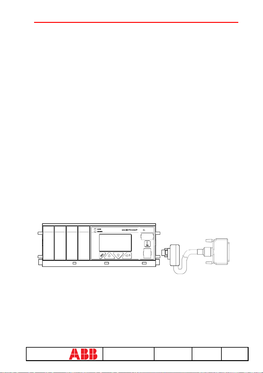
14.8 Status
On this menu it is possible to view any signals of an error in configuration/wiring of the
protection unit and of the circuit breaker. In particular, one or more of the following messages
may be displayed:
1. No alarm
2. L Prealarm
3. T Prealarm
4. L1 Sensor error
5. L2 Sensor error
6. L3 Sensor error
7. Ne Sensor error
8. Gext sensor error
9. TC disconnected
10. Rating Plug error
11. Installation error
12. Device error
13. Invalid Date
14. Configuration error
15. CB status error
Refer to the release user manual for the solution of the errors indicated.
15.SACE PR123/P
protection release
ABB SACE SACE PR010/T RH0029002 L2551 55/67
67
Page 57
15.1 Operation mode menu tree
PR123 UNIT
1. Test
1.
Start automatic test Test report
2.
Start manual test Test report
3.
Start trip test
4.
Start signalling module autotest
5.
Force output S zone sel.
6.
Force output G zone sel.
7.
Release output zone sel.
8.
Start Rc test note 1
2. Measurements
1.
Display currents
2.
Display peak factors
3.
Display voltages
4.
POWERS
1.
2.
3.
5.
Display energies
6.
Display power factor
7.
Display measured frequency
8.
Reset energies counters
9.
Reset measurement history
3. History
1.
Display trip history
2.
Display events
3.
Statistics
1.
2.
3.
4.
5.
6.
7.
4. Config/Param
1.
CONFIGURATIONS >>
2.
Protection parameters
1.
2.
5. Information
1.
Protection unit information
2.
Circuit breaker information
1. Test
2. Measurements
3. History
4. Config/Param
5. Information
6. Status
Display active power
Display reactive power
Display apparent power
Display contact wear
Display total no. prot. trips
Display total no. prot. trips
Display no. manual operations
Display no. prot. operations
Display no. trip failures
Display no. trip tests
Set A PARAMETERS >>
Set B PARAMETERS >>
6. Status
1. Display configuration error
ABB SACE SACE PR010/T RH0029002 L2551 56/67
67
Page 58

PR123 UNIT
CONFIGURATIONS
1. Circuit breaker
1.
Neutral protection parameters
2.
Ground toroide protection parameters note 5
3.
Plant config. parameters
4.
CB TAG Name
5.
User Data
1. Circuit breaker
2. Mains freq.
3. Meas. int.
4. Local bus an. Th.
5. Startup curr. Th.
6. Dual setting
2. Mains frequency
3. Measurement storage period
4. Local Bus analogue threshold
5. Startup current activation threshold
6. Dual setting
1.
Enable dual setting
2.
Default setting
3.
Dual setting on CB close
4.
Dual setting on Vaux Off
5.
Set B on L Bus DI
7. Enable/disable harmonic distortion alarm
8. Modules
1.
Measuring
1.
Voltage transformer parameters
2.
Neutral voltage presence
3.
Positive power direction
4.
Warnings
1.
Phase sequence configuration
2.
Power factor configuration
1.
Operation mode
2.
Communication parameters
1.
Release 1 configuration
1.
Type of signal source Display custom. type
2.
Display source configuration
2.
Release 2 configuration
3.
Release 3 configuration
4.
Release 4 configuration
5.
Input (signalling module configuration)
1.
Type of signal source Display custom. type
2.
Display source configuration
9. Local bus unit
2.
Communication
3.
Signalling module
1.
Local bus unit presence
2.
Release 1 configuration
3.
Release 2 configuration
4.
Release 3 configuration
5.
Release 4 configuration
6.
Release 6 configuration
7.
Release 7 configuration
7. Harmonic distortion
8. Modules
9. Local bus unit
10. Data logger
11. System
note 3
note 4
ABB SACE SACE PR010/T RH0029002 L2551 57/67
67
Page 59
PR123 UNIT
CONFIGURATIONS
8.
Release 8 configuration
10. Data logger
1.
Data logger configuration
2.
Stop data logger event Display custom. type
3.
Reset data logger
4.
Stop data logger
11. System
1.
Display clock
2.
Set language
1. Circuit breaker
2. Mains freq.
3. Meas. int.
4. Local bus an. Th.
5. Startup curr. Th.
6. Dual setting
PR123 UNIT
Protection
parameters
1. L prot.
2. S prot.
3. S2 prot.
4. D prot.
5. I prot.
6. G prot.
7. Ext G prot.
1. Protection L parameters
2. Protection S parameters
3. Protection S2 parameters
4. Protection D parameters
5. Protection I parameters
6. Protection G parameters
7. Protection Ext G parameters
8. Protection U parameters
9. Protection T parameters
10. Protection LC1 parameters
11. Protection LC2 parameters
12. Protection Iw parameters
13. Protection Rc parameters
14. Protection MCR parameters
15. Protection UV parameters
16. Protection OV parameters
17. Protection RV parameters
18. Protection RP parameters
19. Protection UF parameters
20. Protection OF parameters
8. U prot.
9. T prot.
10. LC1 prot.
11. LC2 prot.
12. Iw prot.
13. Rc prot.
14. MCR prot.
7. Harmonic distortion
8. Modules
9. Local bus unit
10. Data logger
11. System
15. UV prot.
16. OV prot.
17. RV prot.
18. RP prot.
19. UF prot.
20. OF prot.
note 5
note 5
note 1
ABB SACE SACE PR010/T RH0029002 L2551 58/67
67
Page 60

NOTES
Only for performing LSIG and presence of residual current in the external toroide.
1
Only if measuring module present.
2
Only if communication module present.
3
Only if signalling module present.
4
Only for performing LSIG.
5
15.2 Indications on operation
• The SACE PR010/T unit can be used with all SACE PR123/P releases by connecting the test
unit to the protection unit with the cable provided, to be inserted in the test connector on the
front.
• It is not necessary for the auxiliary supply to be present in order to use the above releases with
the PR010/T unit.
• The automatic and manual tests must be performed with the circuit breaker off while the trip
test may be performed only with the circuit breaker on; in either case the circulating currents
must be null.
WARNING
For PR123/P releases with a software version prior to 1.0, the following
limitations must be considered:
1. Startup time protection S:
2. Startup time protection S2:
3. Startup time protection G:
4. Startup time protection Gext:
5. Startup time protection D:
0.1 s ≤ Time ≤ 1.5 s step 0.01 s
0.1 s ≤ Time ≤ 1.5 s step 0.01 s
0.1 s ≤ Time ≤ 1.5 s step 0.01 s
0.1 s ≤ Time ≤ 1.5 s step 0.01 s
0.1 s ≤ Time ≤ 1.5 s step 0.01 s
6. Startup current activation threshold not contemplated
7. Protection U threshold: 5% ≤ th ≤ 90% step 5%
8. Minimum custom datalogger activation time not contemplated
A description of the various menus is given below.
15.3 Test
By means of the PR010/T unit it is possible to perform some tests on the protection unit, in
particular:
1. Automatic test
2. Manual test
3. Trip test
4. Sign. mod. autotest
5. Force output S ZS
6. Force output G ZS
ABB SACE SACE PR010/T RH0029002 L2551 59/67
67
Page 61

7. Release output ZS
8. Rc Test
For example, to perform the automatic test it is necessary to follow the procedure described in the
following table:
Key to be
Item selected
pressed
1 Operation mode
x PR123/P
1Test
1 Automatic test
ENTER
A brief description of the various tests will be given below.
15.3.1 Automatic test of the release PR123/P
With the automatic test, a sequence of 13 different tests will be performed at the currents,
voltages, phase shift and phases indicated in the following table:
Test
N°
L1 L2 L3 V12 V23 V31 I [In] V[Un]
uuuu u u
1
uuuu u u
2
uuuu u u
3
uuuu u u
4
uuuu
5
uuuu
6
uuuu u u
7
uuuu u u
8
uuuu u u
9
uuuu u u
10
uuuu u u
11
12
13
Phase Amplitude Phase shift
Φ
3.0 1 30°
5.0
10
15
0.3 1 0°
3
0.3 1 210°
3
5
10
15
uu u
uu u
0.0 0.4
1.3
For example test n° 5 is performed with:
IL1=0,3 In
IL2=IL3= 0 In
V12=V23=V31= 1 Un
ABB SACE SACE PR010/T RH0029002 L2551 60/67
67
Page 62

Phase shift 0° (cosΦ=1)
The trip times of the release in the various tests will depend on the settings of the protections; on
the display the PR010/T unit will show the trip time and the result of the test (OK/FAILED).
At the end of the test it is asked whether to record a test report which may later be downloaded on
a PC.
15.3.2 Manual test
The manual test allows the release trip time to be tested with the desired load condition, in
particular it offers the possibility of selecting the current value in a range between 0.00 and 16.00
In, the voltage value in a range between 0.0 and 1.3 Un, the phase shift between -180° and +180°
with step 0.75°, and of selecting the phases involved in the test (L1, L2, L3, Ne, Gext, V1, V2,
V3).
The release trip time will depend on the settings of the protections; on the display the PR010/T
unit will show the trip time and the result of the test (OK, FAILED).
At the end of the test it is asked whether to record a test report which may later be downloaded on
a PC.
15.3.3 Trip test
With this test it is possible to send a command to turn off the circuit breaker, thus checking the
functionality of the protection opening system.
The trip test command is accepted by the protection unit only if the circuit breaker is on.
15.3.4 Sign. mod. autotest
When this item is selected, the autotest of the signalling module is launched. Refer to the
signalling module manual for further information on this function.
15.3.5 Force output S ZS
Activates the zone selectivity output of the protection S; this command allows checking of the
zone selectivity function on the system.
15.3.6 Force output G ZS
Activates the zone selectivity output of protection G; this command allows checking of the zone
selectivity function on the system.
15.3.7 Release output ZS
Deactivates both the zone selectivity outputs of the protections S and G; this command allows
checking of the zone selectivity function on the system.
ABB SACE SACE PR010/T RH0029002 L2551 61/67
67
Page 63

15.3.8 RC Test
Activates the test of the protection RC. Refer to the protection manual for further information on
this function.
15.4 Measurements
It is possible to display the following measurements:
1. Currents
2. Peak factors
3. Voltages
4. Powers
5. Energies
6. Power factor
7. Frequency
8. Reset energies
9. Reset meas. history
For example to display the current measurements, the following selections must be made:
Key to be pressed Item selected
1 Operation mode
x PR123/P
2 Measurements
1 Currents
ENTER
15.5 History
Under the history menu is the display of the history for the openings of the protection tripped, the
events and some statistical information on the openings of the release.
For example to display the history of the openings (trip history), the following selections must be
made:
Key to be
Item selected
pressed
1 Operation mode
xPR123/P
3 History
1 Trip history
ENTER
ABB SACE SACE PR010/T RH0029002 L2551 62/67
67
Page 64
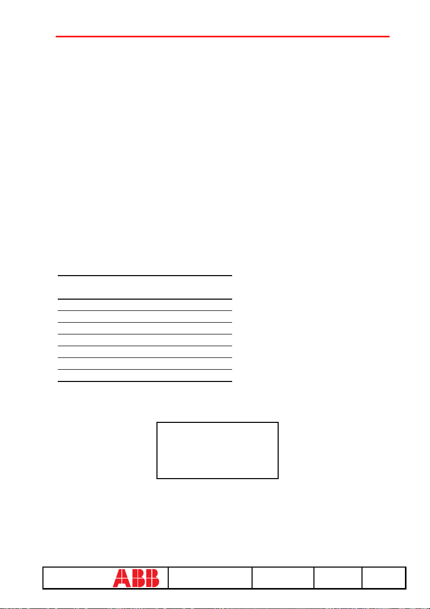
15.6 Configurations/parameters
It is possible to display and even modify the configurations and parameters of the release.
15.6.1 Configurations
The configuration parameters available are divided into:
1. Circuit breaker
2. Mains freq.
3. Meas. int. (Measurement interval)
4. Local bus an. Th. (Local bus analog threshold)
5. Startup curr. Th. (startup current threshold)
6. Dual setting
7. Harmonic distortion
8. Modules
9. Local bus unit
10. Data logger
11. System
For example, starting from the main menu, selecting:
Key to be
Item selected
pressed
1 Operation mode
x PR123/P
4 Config./Parameters
1 Configurations
1 Circuit breaker
1 Neutral protection
ENTER
enters the screen that displays the configuration parameters of the neutral protection and the
following screen appears:
Neutral protection
Enable: ON [OFF]
Threshold: 50[...]%
Pressing the ENTER key launches editing mode (the cursor starts blinking); using the keys and
the cursor is positioned on the desired parameter and the keys and are used to modify the
value of the parameters in the allowed range.
ABB SACE SACE PR010/T RH0029002 L2551 63/67
67
Page 65

15.6.1.1 Local bus unit
From the CONFIGURATIONS menu it is possible to set the parameters for operation of the
release unit on the local bus, selecting:
Key to be
Item selected
pressed
1 Operation mode
x PR123/P
4 Config./Parameters
1 Configurations
9 Local bus unit
... ...
At this point it is possible to choose one of the following items:
1. Presence
2. Release 1
3. Release 2
4. Release 3
5. Release 4
6. Release 6
7. Release 7
8. Release 8
Selecting "Presence" sets the presence/absence of a unit on the local bus.
Selecting Release x the configuration parameters of release x on the local bus unit are read/set, for
example selecting:
Key to be
Item selected
pressed
... ...
4 Release 3
1 Source
The setting of the activation signal of release no. 3 is displayed; pressing the ENTER key
launches editing mode (the cursor starts blinking); the setting of the activation signal is changed
using the keys and .
If "Custom" is selected, when ENTER is pressed the current setting is displayed, for example:
ALARM 1 4...6
→ L Pre-alarm
L Timing
→ S Timing
ABB SACE SACE PR010/T RH0029002 L2551 64/67
67
Page 66

Where the arrows indicate which elements of the ALARM 1 block are selected.
With the keys and the previous/next screen is displayed and with the keys and the
selected element is activated/deactivated (the arrow next to the element is displayed/removed).
There are 18 blocks, each of which is made up of eight elements and is displayed in three
consecutive screens; up to 8 elements may be activated for each block.
On the last screen of each block it is possible to define the AND/OR logic applied to the selected
elements and the minimum release activation time.
15.6.2 Parameters
The PR123/P protection unit has two alternative parameter sets, Set A and Set B; the parameter
reading/programming menu contemplates the choice of the set of parameters to be displayed/
edited:
1. Set A
2. Set B
After having selected the test on which to operate, the menu for choosing the type of protection is
accessed:
1. L prot.
2. S prot.
3. S2 prot.
4. D prot.
5. I prot.
6. G prot.
7. Ext G prot.
8. U prot.
9. T prot.
10. LC1 prot.
11. LC2 prot.
12. Iw prot.
13. Rc prot.
14. MCR prot.
15. UV prot.
16. OV prot.
17. R V prot.
18. RP prot.
19. UF prot.
20. OF prot.
ABB SACE SACE PR010/T RH0029002 L2551 65/67
67
Page 67

For example, selecting:
Key to be
Item selected
pressed
1 Operation mode
x PR123/P
4 Config./Parameters
2 Parameters
1Set A
1 Protection L
ENTER
enters the screen that displays the parameters of protection L and the following screen appears:
L prot t=k/i2[...]
Threshold: x.xx In
Time: x.xx s
Thermal mem: ON[OFF]
Pressing the ENTER key launches editing mode (the cursor starts blinking); using the keys and
the cursor is positioned on the desired parameter and the keys and are used to modify the
value of the parameters in the allowed range.
15.7 Information
On this menu it is possible to view some information on the protection unit and the circuit
breaker.
The menu is divided into:
1. Protection unit
2. Circuit breaker
For example, starting from the main menu, selecting:
Key to be
Item selected
pressed
1 Operation mode
x PR123/P
5 Information
Circuit breaker
ENTER
ABB SACE SACE PR010/T RH0029002 L2551 66/67
67
Page 68

enters the screen that displays information on the circuit breaker:
Device: E1B800/4P
Rated Current: xxxxA
sn: xxxxxxxxxx
Pressing the keys and passes to the display of the next/previous screen:
Install: xx/xx/xxxx
Maint: xx/xx/xxxx
15.8 Status
On this menu it is possible to view any signals of an error in configuration/wiring of the
protection unit and of the circuit breaker. In particular, one or more of the following messages
may be displayed:
1. No alarm
2. L Prealarm
3. T Prealarm
4. L1 Sensor error
5. L2 Sensor error
6. L3 Sensor error
7. Ne Sensor error
8. Gext sensor error
9. TC disconnected
10. Rating Plug error
11. Installation error
12. Device error
13. Invalid Date
14. Configuration error
15. CB status error
Refer to the release manual for the solution of the errors signalled.
ABB SACE SACE PR010/T RH0029002 L2551 67/67
67
 Loading...