

Page 1
Bushing Potential Device,Type PBA2
PTAE-APD903
IZUA 7711-210
Instructions for Installation and Maintenance
Page 2
All possible contingencies which may arise during installation, operation, or maintenance, and all details and
variations of this equipment do not purport to be covered by these instructions. If further information is desired
by purchaser regarding his particular installation, operation or maintenance of his equipment, the local ABB Inc
representative should be contacted.
2
ABB
Page 3
Description
Application
The condenser bushing potential device is a means for
securing small amounts of 60 hertz power at 115 volts
and 66.4 volts from high voltage lines through the medium
of the condenser bushing. For 115kV and higher voltages
this device is the most economical means of securing
such small amounts of power.
These devices provide a 115 and 66.4 volt output which
is substantially proportional to the system line-to-ground
voltage and in phase with it. This output is commonly
used to energize synchroscopes, voltmeters, and voltage
responsive relays. The device accuracy is not adequate
for use with metering instruments where revenue is involved.
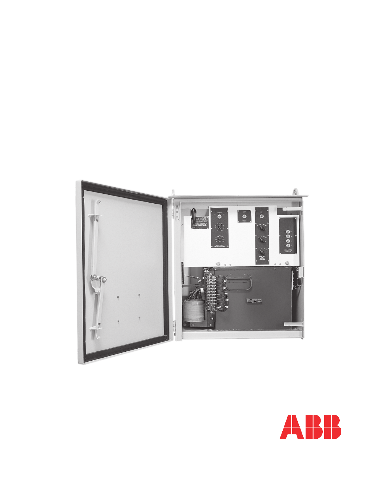
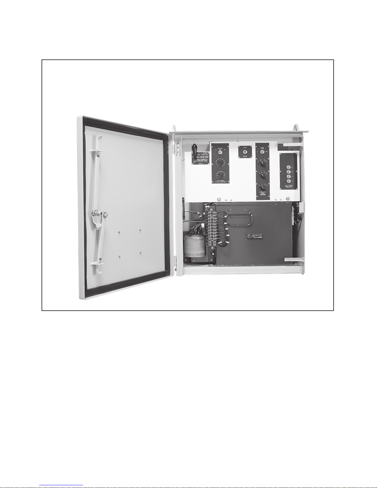
Construction
The potential device is built in an outdoor, weatherproof,
steel housing arranged for mounting on the side of an oil
circuit breaker or transformer in the vicinity of one of the
condenser bushings. A special cable assembly of
weatherproof construction, and with a grounded external
shield, connects the potential device to one of the metallic
layers of the condenser bushing.
The device network (see Fig. 6) consists of a main transformer
having adjustable reactance, an auxiliary transformer of
adjustable ratio, a tapped capacitor to correct burden power
factor, a protective spark gap, and a dead-front adjusting
panel.
A grounding switch permits de-energizing the device, and a
heater (to be energized from an external voltage source)
prevents internal sweating of the housing.
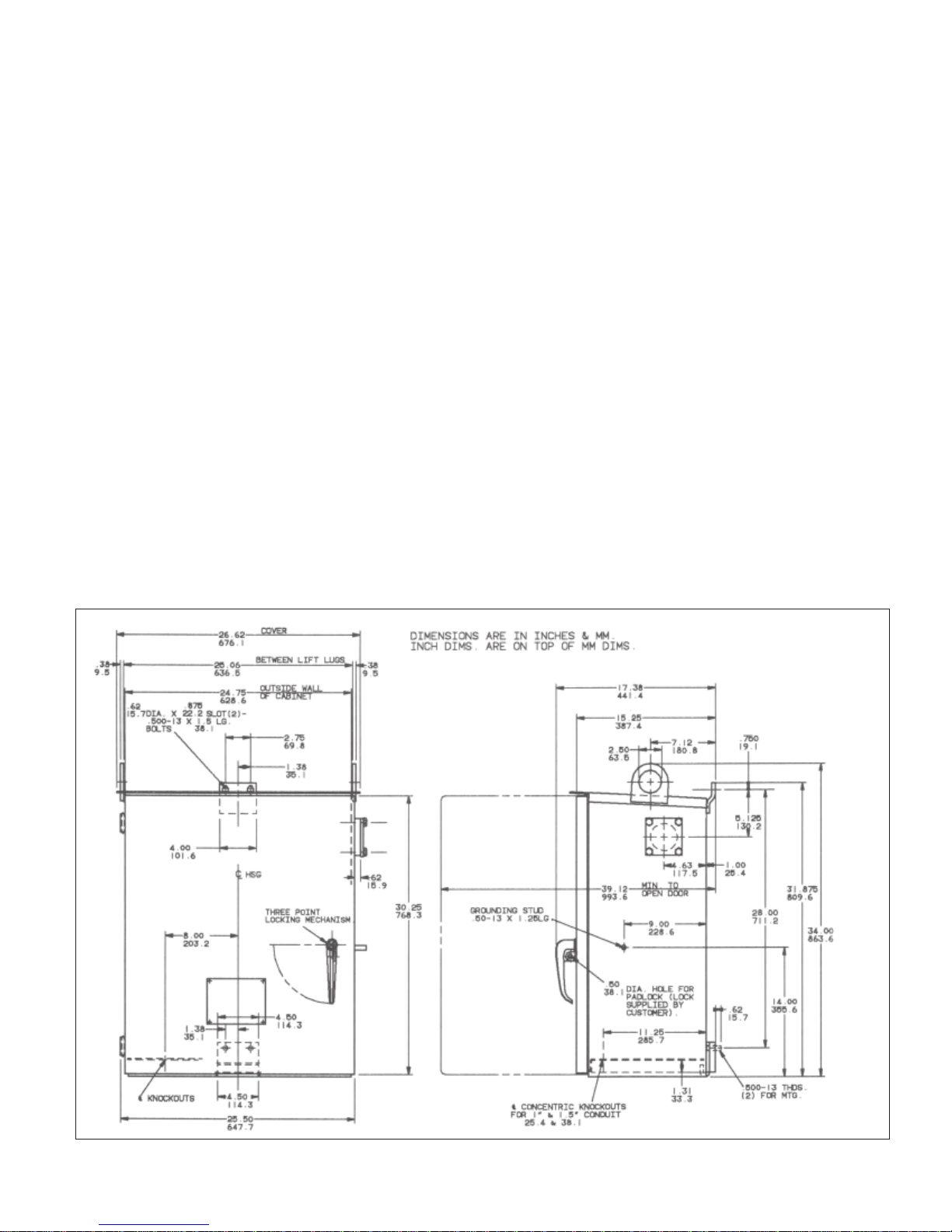
Standardized mounting dimensions permit the interchangeability
with most standard ABB or Westinghouse units sold since
the middle of 1934. The standard device is electrically usable
for most bushings having capacitance taps per IEEE
C57.19.01-2000 Type A: Normally Grounded having the tap
on the second metallic layer above ground potential
includes substan
tured since the middle of 1935 and having a voltage rating of
115kV or higher. Cable lengths (see Fig. 2) are also standard
for circuit breakers, but special lengths are general for transformers. End fittings of cables are common for all.
tially all Westinghouse bushings manufac-
. This
Figure 1: Outline and Mounting
ABB
3
Page 4
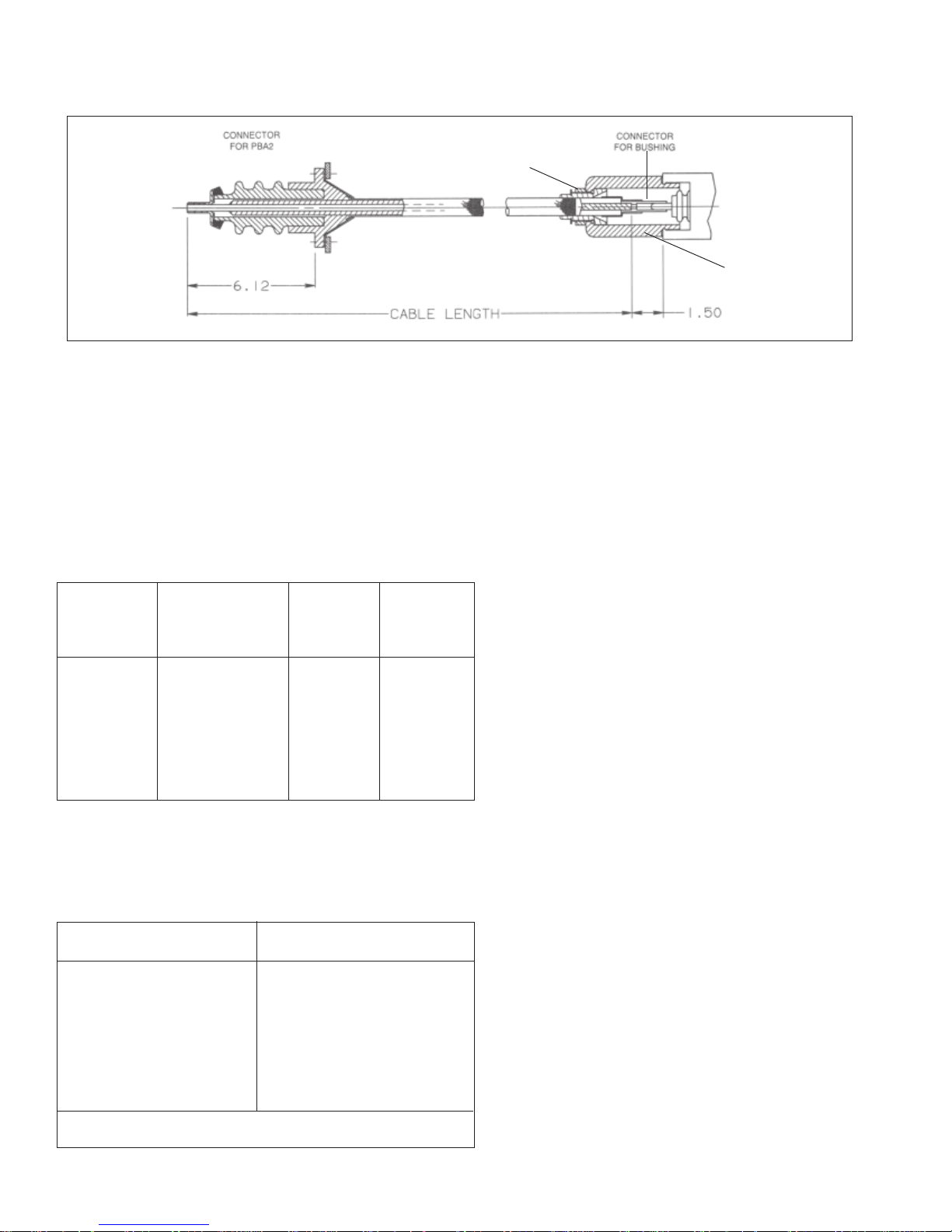
PBA CABLE DRAW NUT
"
Figure 2: Cable Lead-in Assembly
Rating
Each device has output voltages of 115 and 66.4 for the
main burden (terminals S1, S2, S3) and an auxiliary winding
provides the same voltages (terminals Z1, Z2, Z3) for use
when broken-delta connections are required.
The burden ratings of the standard devices, when used with
standard bushings in each case, are shown in Table 1.
Table 1
System System Max. Watts* Device
Voltage Voltage Total Style**
Line-To-Line Line-To-Ground Burden ***
115 kV 66.4 kV 25 3D69822G01
138 kV 79.7 kV 35 3D69822G01
161 kV 93.0 kV 45 3D69822G02
230 kV 133 kV 80 .....................
287 kV 166 kV 100 .....................
330-345 kV 191-199 kV 150 .....................
* In no case shall the burden on the auxiliary winding (Z1, Z2, Z3) exceed 75 watts.
** Styles do not include lead-in cable, see Table 2.
*** These designs are for ABB or Westinghouse bushings. Bushings by
other vendors require special PBA configuration.
PBA CONNECTION
HOUSING
"
Since the device rating is a function both of the system
voltage and of the particular bushing capacitance values, it
is obvious that special bushings, or standard bushings
used at non-standard voltages may have burden ratings
which are at variance with the foregoing tabulation. In this
connection it is to be noted that the auxiliary capacitance
built into each device varies according to the device
ap
plication. See page 10 “Calculation of Approximate
Adjustment.”
Performance
The Type PBA2 Potential Device is a Class”“A” device as
defined by AIEE Standard # 31 and NEMA Standards
SG4-1968. The regulation characteristics with respect to
varying line voltage and varying burden meet the limits
established by these standards.
Since this type of device is basically a series-tuned
device it is sensitive to the system frequency. For small
frequency deviations there is practically no ratio effect,
but there is a slight phase shift. For example, a deviation
of one hertz in 60 will produce a phase shift up to 2
degrees, depending on the particular bushing device and
system voltage. The greatest phase shift is experienced
when the potential device is loaded to its rating, and when
the normal system voltage is low relative to the bushing
rating.
Table 2. Cables with Type A Connectors
Cable Length* Style#
96" 3D69768G01
120" 3D69768G02
144" 3D69768G03
168" 3D69768G04
192" 3D69768G05
216" 3D69768G06
240" 3D69768G07
*Cable lengths other than those listed can be ordered if necessary
4
When high-speed directional relays are energized from
this device, it is recommended that the basic burden be
power factor corrected to 100%, or slightly leading, and
that the device be loaded to its rating in watts (as shown
on the nameplate), by adding parallel resistance if
necessary. The purpose of this is to reduce to a minimum
the possibility of incorrect relay operation, which might
result from device output transients following a system
short circuit extremely close to a device.
ABB
Page 5

Erection
The potential device may be lifted from its crate or pallet
and handled by means of the two lifting lugs on the side of
its roof to mount it on the circuit breaker or the transformer.
Depending on the particular breaker or transformer bracket
provided for the lower edge of the potential device, proceed
as follows (see Fig. 1):*
a. If the lower device support on the transformer or breaker
carries two tapped holes then bolt the J bracket, which
is shipped loose with the potential device, to this pad
using the two countersunk head bolts provided. There
is a notch in the center of the rear lower flange of the
device, which will fit into the hook provided by this J
bracket. Rest the weight of the potential device into
this bracket and place the two bolts into the two slots
of the upper device support, and secure these in place.
b. If the transformer or breaker carries a lower device
support consisting of a bent steel bar, and with two
notches cut into its edge instead of two tapped holes,
then the J bracket may be scrapped and the potential
device rested directly on the notched bar. The upper
end is bolted into place with the two bolts.
c. In either case, the paint shall be scraped away from the
upper pad where it is bolted against the corresponding
pad on the breaker or transformer in order to assure a
good ground connection at this point.
d. The primary connection is made by installing the high
voltage cable assembly of Fig. 2. This is done with the
bushing grounded. The cable is installed by
t
he mounting flange cover from the side of the po
device housing and removing the cover from the tap
receptacle on the bushing flange. The tap receptacle
on the bushings of recent manufacture may be found
filled with approximately one pint of transformer oil, which
will drain out when the cover is removed. Discharge the
bushing tap layer by touching the socket
contact with a grounded wire.
removing
tential
1. If the bushing is ABB O plus C or other type that
permits addition of transformer oil to the test tap with
the tap cover in place, you may choose to fill the PBA
connector housing with transformer oil. In this case,
do not add the petrolatum to the PBA connector housing.
2. Otherwise, pack the inside of the PBA connector hous
ing
with the petrolatum provided, taking care to leave no
air pockets.
e. Push the bushing connector into the tap, then thread the
PBA connector housing into the threaded portion of the
bushings tap. Tighten by hand, approximately 1/4 turn
after the gasket is in contact with both the tap and the
connector housing. Lubricate the gasket with a thin
application of transformer oil or petrolatum whichever is
being used.
f. Turn the PBA cable draw nut clockwise, until tight.
g. If you have chosen to fill the PBA connector housing with
transformer oil, do so now. Please see the bushing's
application literature for filling instructions and oil expansions
space requirements.
h. Place the porcelain end of the cable assembly into the
hole in the side of the potential device housing.
Bolt the two flanges in place using the hardware
provided. The composition flange at the cable end
is also the gasket. Draw up the bolts progressively
around the cable so that there is not excessive pressure
at any point. Tighten up the bolts only sufficient to create
a slight bulge all around the edge of the composition.
i. Connect the internal jumper connection in line with
diagram of Fig. 6 by opening the
partially dropping the front panel assem
It is suggested that when a device is installed and con
PBA'S door and
bly.
nected
that its voltage adjustment be set to a minimum (and the
ground switch opened) until such time as the normal burden is connected and the device adjusted.
* If the device is to be mounted on equipment that is not
manufactured by ABB, the mounting arrangement may
be slightly different than described here.
ABB
5
Page 6

Adjusting
General
The Type PBA2 is a ‘resonant’ or ‘in-phase’ device having
Class’“A” performance, and hence it must be adjusted or
tuned to match a specific bushing and a specific burden. A
reference voltage of known value and phase angle position
is required to make this initial adjustment. This reference
voltage is usually supplied from the secondary voltage of a
potential transformer of the desired ratio, which is connected
line-to-ground to the same phase of the transmission line
as the bushing to which the potential device is mounted.
However, the reference voltage may be taken from another
potential device which has been previously adjusted, or it
may be taken from the low voltage secondary of the power
transformer provided it is known that voltage is in phase
with the line-to-ground voltage of the transmission line. The
object is to have a reference voltage for comparison, this
reference voltage to be approximately 115 volts (or this value
divided by 1.73) as may be decided upon for the device
output, and this voltage to be in phase with the transmission
line-to-ground voltage.
There are three adjustments provided on the device adjusting
panel; these are power factor correction of the burden, phase
angle adjustment of the transformer to series tune the
bushing reactance, and voltage adjustment to control the
burden voltage. The phase angle adjustment shows its
effect by shifting the phase angle of the secondary or output
voltage. The controls on the adjusting panel are marked
power-factor correction, volt-amperes, phase-angle, and
inductive reactance, and voltage adjustment.
The numbers on the respective adjustments are in terms of
volt-amperes of power factor correction; active turns of
reactance winding and volts-primary of the ratio transformer.
The values are useful in making the device adjustment.
It is desirable to adjust the device with the final burden in
place. If this is not possible then a synthetic burden shall be
used having the identical volt-ampere and power factor
characteristics of the actual burden.
The adjustment procedure requires a voltmeter of fairly high
impedance to check the magnitude of the output voltage,
whether 115 volts or 66.4 volts (note that the ratio of these
two voltages in the output is fixed so that only one of them
need be adjusted and checked). To check the phase angle
of the output voltage requires either a phase angle meter
having two voltage coils, a low voltage voltmeter, or an
oscilloscope. The oscilloscope is probably the most
satisfactory
for phase angle adjustment.
If the reference voltage being used is the exact magnitude
desired then the entire adjustment can be made by using
two voltmeters (one reading about 150 volts, and the other
about 5 volts) by connecting the ground of the reference
and the ground of the device output together and then
checking voltage between the line terminals, first with the
150 scale voltmeter and finally with the 5 scale voltmeter.
The device will be correctly adjusted when the voltage
between line terminals is a minimum (less than 1 volt).
Procedure
Power Factor Correction
Correct the power factor of the burden to unity, or to a slightly
leading angle. This is the first step and may be done by
switching in an amount of capacitive volt-amperes, to match
the reactive volt-amperes of the burden. In the case of
delta-connected burdens operating from a bank of three
potential devices, it may be simplest to excite the total burden
from a separate voltage source and to adjust the capacitors
to secure unit power-factor in each phase. This can be done
by grounding terminal S3 (Fig. 3) of each device and applying
the three-phase test voltage to the three S1 terminals, or
the three S2 terminals, depending on the voltage. The primary
shall be de-energized for this test and the ground switch
open.
If in this test the protective gap flashes over this may be
stopped by making a radical change in the phase angle
setting, such as by reversing the BUCK-BOOST switch, or
by changing large sections of turns in the tapping arrangement.
As an alternative, the reactive volt-amperes can be calculated
and the corresponding capacitive volt-amperes set on each
device.
Phase Angle and
Voltage Adjustment
There is some interdependence between the phase angle
and voltage adjustment and so these will be considered
together. These are the final adjustments and are best made
with the final burden (power factor corrected) connected in
its final form to the potential device. The device adjustment
is basically a single-phase procedure, even when connected
into a 3 phase group.
6
ABB
Page 7

Figure 3: Connection Diagram
For this adjustment the device must be connected to its
final condenser bushing, with normal line-to-ground voltage
on the bushing stud, and with a reference voltage available
for comparison. See also ADJUSTING-GENERAL above.
The ratio or output voltage adjustment is a matter of voltage
magnitude only, and this is checked by voltmeter reading.
The phase angle of the output voltage may be checked by
low reading voltmeter, by phase angle meter or by oscillo
as previously mentioned.
Fig. 4 is the circuit diagram for checking the phase angle
and ratio using the oscilloscope with vertical and horizontal
sweeps each energized at 115 volts 60 hertz. The oscillo
ABB
scope,
scope
shall be adjusted so that the total deflection in each the
vertical and the horizontal directions is roughly the same.
The reference and the output voltages are in phase when
the trace on the oscilloscope is the nearest possible to a
single straight line. Some variation in the wave form of the
two voltages may prevent the trace from ever becoming a
perfect straight line. When the voltages are out of phase,
the trace tends to be an ellipse; it would be a circle with the
two voltages 90 degrees out of phase. The oscilloscope as
used here will not distinguish in-phase from 180o out-of-phase.
7
Page 8

Make up the circuit of Fig. 4 with the ground switch of the
device in the closed position, which de-energizes the device.
Place all of the rotary switches and the toggle switch of the
phase angle adjustment in the zero position and set the
voltage adjustment dials to maximum (which is primary
voltage and hence will give the minimum output voltage).
Next open the device ground switch and shift the voltage
adjustment dials to obtain approximately 115 volts S1 to S3.
Note the oscilloscope trace; it is very probably an approximate
ellipse. To determine which direction to proceed from here,
switch in 24 or 48 turns of the phase angle adjustment and
then note the position of the buck-boost switch which gives
the nearest to a straight line trace on the oscilloscope. This
simple check should establish the correct position of the
buck-boost switch and then the finer adjustments of the
phase angle switches is a straight forward procedure to secure a
straight line trace on the oscilloscope. Start by first trying the
larger steps (192 turns is the largest step) and if any step is in
excess of that required then drop back to the next lower turns
in the same switch. For example, with the three rotary switches
in the zero position, and if 192 is then found to be excessive
then return the toggle switch to zero and try 144 turns on the
top rotary switch. If this is still excessive then turn the top
rotary switch back down to 96 turns, and so on, until some
points is reached which is short of the required amount. Then
proceed to the middle and lower rotary switches in order until
the closest setting is reached. The total number of turns
tapped in is the sum of the settings on the three rotary
switches and the 0 to 192 toggle switch. Reference to figure
5 will give an idea of the effect of the various number of turns
of the reactance winding, both buck and boost.
Figure 4: Test Circuit Using Oscilloscope
8
ABB
Page 9

Figure 5: Curve of Ohms versus Turns of Reactance
ABB
9
Page 10

Excessive transformer reactance (refer to Fig. 5) will result in
a lagging voltage at the burden, and vice versa.
When a straight line is being approached on the oscilloscope,
the output voltage shall be checked and readjusted to the
desired value. The final setting is with the correct output
voltage and with the oscilloscope trace the closest possible
to a straight line, bearing in mind that differences in wave
form of the two voltages will prevent a perfect straight line.
To check for polarity correctness, connect terminal S3 to the
ground of the reference voltage and then check the voltage
between S1 terminal and the polarity terminal of the reference
voltage. With correct polarity this voltage will be zero and
with reversed polarity the voltage will be approximately 230.
If an oscilloscope is not available then use two voltmeters,
one high scale and one low scale, and with these measure
the difference or error voltage and the output voltage. This
plan, which uses the difference voltage, pre-supposes that
the reference voltage is of the exact magnitude, which is
desired for the adjusted device.
In the case of delta-connected three-phase burdens, it is
necessary to make preliminary or approximate adjustments
of each device first and to then re-check and trim each device
one or more times until the three phase voltages to ground
are equal and each in phase with its reference voltage.
When final adjustment is accomplished, with the burden
connected, check voltage H2-H3. This voltage shall not
exceed 172V. Voltage in excess of 172V indicates excess
burden connected to the device and excess voltage on
the primary of the transformer.
Calculation of Approximate Adjustment
If the capacitance values C1, C2 and C3 of Fig. 6 are known,
then it is possible to calculate the approximate adjustment
of a device when used with a particular bushing at a specific
line voltage. It is assumed that the burden is corrected to
substantially unit power factor. For this purpose the nominal
values of C3 (in the potential device) are,
Device C3
S#3D69822G01 2000pF
S#3D69822G02 3000pF
All others Check the device for value
The values of C1 and C2 shall also be used in picofarads.
If C4 is obtained by measuring a bushing mounted in a
grounded structure, it will contain appreciable stray
capacitance to ground. Since this stray capacitance is not
effective in the circuit of the potential device it is more
accurate to use 0.85C4.
Figure 6: Schematic Diagram
10
ABB
Page 11

Capacitance C2 similarly measured will contain an
insignificant percentage of stray capacitance.
Capacitance C1 is then:
C2 x 0.85C4
C1=
C2 – 0.85C4 (1)
Approximate adjustments may be calculated using the
nomograph (Fig. 7) and the instructions on the following
pages or the equations below.
First calculate the bushing tap voltages as if no potential
device burden were present. This is determined from the
relation:
e = E
C1
C1 + C2 + C3 (2)
Where e is the open circuit tap voltage in volts and E is the
actual system line-to-ground voltage at the condenser bushing.
The dial setting of the voltage adjustment should then total,
dial volts = 173 — e
44.1 (3)
For the phase angle adjustment it is necessary to know the
capacitive reactance XC which must be series tuned. This
value in ohms is, for 60 hertz:
XC = 10
12
377* (C1+C2+C3) (4)
*377 = 2 πf, with f = 60 hertz
Using this value of XC refer to curve Fig. 5 and using the
same value of reactance determine whether the device
reactance switch is to be in the BUCK or BOOST position
and further determine the number of turns required in the
phase angle adjustment. Now set the rotary switches and
toggle switch of the phase angle adjustment so that the
total turns are the same as that determined from the curve.
Figure 7: Nomograph for PBA2 Potential Device
ABB
11
Page 12

Use of nomograph for PBA 2 potential device
1. Calculate the sum of C1 + C2 + C3 using capacitance
values of Fig. 3. Mark that value on the first scale on the
monograph.
2. Mark C1 on the second scale
3. Draw a straight line through the points on the C1 + C2 +
C3 scale and the C1 scale extending to the reference line.
4. Locate the system voltage, which the PBA2 device is
measuring on the line volts scale.
5. With a straight line connect the points on the reference
line (where the first connecting line intersects the reference
line) and the line volts scale, extending to the dial volts scale.
6. Read the correct value for the dial setting of the voltage
adjustment on the dial volts scale.
7. Read the number of turns buck or boost to switch in on
the furthest left scale opposite the C1 + C2 + C3 point.
Example
C1=300, C2=3000, C3=3000,
Line Volts=138 kV
C1+C2+C3=300+3000+3000=6300 Picofarads
Reading the Scale – Dial Volts=87
Turns Boost=42
Unusual Combinations
Unusual combinations of voltage, bushing, potential device
and burden can be checked for workability by calculation.
Unit power factor burdens are assumed.
Equation (3) above means that the open circuit tap voltage
e will be workable if it lies between 3000 volts and 7600
volts. Of course with e as large as 7600 it would not be
possible to carry any burden on the device, since the
operating tap voltage rises with added burden, and 7600 is
the limiting voltage on the transformer primary.
If the exploration of the paragraph above shows the
combination to be workable then its burden carrying ability
can be roughly checked by the following:
The reactance XC of equation (4) must be in the range of
125,000 to 800,000 ohms for 60 hertz, or 104,000 to
670,000 ohms for 50 hertz.
Let ex = maximum permissible reactance
voltage.
then ex = (7600)2 - e
Max. watts = ex
XC K (6)
Constant K from empirical equation K = .95 + .078XC/
100,000 but not less than 11.
2
e
x
(5)
Application Notes
Heater
Each device contains two vitreous enameled resistors of
1200 ohms each. These are to be energized from an
external source for the purpose of preventing the internal
sweating of the device. Sweating is objectionable from the
point of view of corrosion and also it may temporarily affect
some of the high voltage insulation resulting in adjustment
unbalance. The resistors may be connected series,
parallel or singly and may in any arrangement be energized
by either 115 or 230 volts giving a range of 5.5 to 88 watts.
The suggested arrangement of the two in parallel at 115
volts gives 22 watts of heating.
Protective Gap
The protective gap across the primary of each device is
sealed to prevent modification of its setting by reason of
atmospheric changes. It is set to breakdown at 15 to 16
kV 60 hertz, which is sufficiently high to permit operation of
the device indefinitely at line-to-line system voltage. The
gap will flashover if a short, or overload, is placed on the
output of the device, since the primary voltage of the
device rises in proportion to the output watts. Continued
arcing of the gap will not cause damage for the reason that
the current which can flow is limited to a very low value by
the impedance of the condenser bushing.
Over voltage Operation
These potential devices may be operated at over voltages
up to line-to-line potential for several hours without damage.
Over voltages will result if one or two lines of ungrounded
system become grounded.
Fusing of Burdens
Inasmuch as the possible output is limited by the protective
gap there is no object in attempting to protect burdens by
use of fuses.
12
ABB
Page 13

Figure 8: Transformer Tap and Ratio Chart
Operating Tap Voltage
The primary of the device transformer is designed for
continuous operation at voltages not in excess of 7600
volts. Therefore, it is necessary to check the voltage
H2-H3 after any alteration to be certain this voltage
does not exceed 172V.
Adjustment-Need For
The adjustment of a potential device is in effect a
“tuning” procedure to affect a “match” between con
ABB
denser
bushing, a potential device and a burden. Therefore,
since any one of these is not a perfect duplicate of any
other of its own kind, it is necessary to completely
re-adjust when any one of the combination is changed.
Auxiliary Winding
The output winding with terminals Z1, Z2 and Z3 is
designed for a maximum of 75 watts, and no more
than this amount of burden shall be connected to the
Z terminals, even though the total rating of the device
may be in excess of 75 watts in some cases.
13
Page 14

Grounding
Any one terminal of either the “S” winding or the “Z”
winding of a device may be grounded (it is not necessary)
if desirable for the purposes of the connected burden.
The primary of the device transformer is grounded to
the device housing and it in turn is grounded to the
transformer or breaker tank by the device mounting
and by the sheath of the lead-in cable. The current,
which flows to ground, is a small fraction of an ampere.
Type of Burden
Burdens having ferro-magnetic cores shall be
sub
stantially linear in impedance to 1.73 times normal
voltage.
Broken Delta Burdens
The burden connected to the Z terminals, under
condition of maximum zero sequence voltage, shall
not exceed 50% of the device rating.
Record of Adjustment
A record of the adjustment setting of a given device in
a given location will consist of a record of the following:
Volt-amperes of power factor correction, “Buck” or
“Boost” of reactance switch, total turns of reactance
tapped in, and total volts on primary of voltage
adjustment transformer.
Trouble Shooting
Inability to make voltage of phase angle adjustment
calls for the following:
1. Recheck the reference voltage for phase angle po
2. Recheck the circuit being used for adjustment.
3. Check accuracy of voltmeter being used, and also
of phase angle meter if one is being used. Note that
phase angle meters may not register correctly if coils
are not operated at their rated voltage or current.
sition.
4. Recheck degree of power factor correction.
5. Calculate the approximate adjustment in line with
,
sections on “Calculation of Approximate Adjustment”
and”“Unusual Combinations” to be sure device is
ap
plicable to the combination at hand.
6. Check for loose, grounded or open connections within
device.
7. Frequency other than 60 hertz on system, such as
25 hertz or 50 hertz.
Variability in performance of device may be due to some
loose connections, to electrical leakage to ground at
the primary voltage of the transformer, or to shorted
turns of transformer primary. The electrical leakage might
be in the bushing tap, in the lead-in cable or in the
potential device.
Flashing of gap means an overburden on the device, or
a ground or short either inside or outside the device, or
a defective gap. The gap shall flash over in the region
15 to 20 kV 60 hertz.
A shifting of adjustment with passage of time can be
indicative of deterioration of the condenser bushing.
Poor ratio regulation will result from increased losses in
the device, and this may result from poor connections
or shorted turns in transformers.
Maintenance
The bushing potential device is a piece of static
equipment and requires no maintenance other than to
see that the heater is energized when it is required, to
see that the paint finish is kept in good condition, and
to be sure no extraneous objects rest on the lead-in
cable. If there is suspicion of change in voltage output
then see Trouble Shooting above.
14
ABB
Page 15

Notes
ABB
15
Page 16

DISCLAIMER OF WARRANTIES
AND LIMITATION OF LIABILITY
THERE ARE NO UNDERSTANDINGS, AGREEMENTS,
REPRESENTATIONS OR WARRANTIES, EXPRESSED
OR IMPLIED, INCLUDING WARRANTIES OF
MERCHANTABILITY OR FITNESS FOR A PARTICULAR
PURPOSE OTHER THAN THOSE SPECIFICALLY SET
OUT BY AN EXISTING CONTRACT BETWEEN THE
PARTIES. ANY SUCH CONTRACT STATES THE ENTIRE
OBLIGATION OF SELLER. THE CONTENTS OF THIS
DOCUMENT SHALL NOT BECOME PART OF OR
MODIFY ANY PRIOR OR EXISTING AGREEMENT,
COMMITMENT OR RELATIONSHIP.
THE INFORMATION, RECOMMENDATIONS, DESCRIPTION
AND SAFETY NOTATIONS IN THIS DOCUMENT ARE
BASED ON OUR EXPERIENCE AND JUDGEMENT WITH
RESPECT TO BUSHINGS. THIS INFORMATION SHOULD
NOT BE CONSIDERED TO BE ALL INCLUSIVE OR
COVERING ALL CONTINGENCIES. IF FURTHER
INFORMATION IS REQUIRED, ABB INC. SHOULD BE
CONSULTED.
NO WARRANTIES, EXPRESSED OR IMPLIED, INCLUDING
WARRANTIES OF FITNESS FOR A PARTICULAR
PURPOSE OR MERCHANTABILITY, OR WARRANTIES
ARISING FROM COURSE OF DEALING OR USAGE OF
TRADE, ARE MADE REGARDING THE INFORMATION,
RECOMMENDATIONS, DESCRIPTIONS, AND SAFETY
NOTATIONS CONTAINED HEREIN. IN NO EVENT WILL
ABB INC. BE RESPONSIBLE TO THE USER IN CONTRACT,
IN TORT (INCLUDING NEGLIGENCE), STRICT LIABILITY
OR OTHERWISE FOR ANY SPECIAL, INDIRECT, INCIDEN
TAL,
OR CONSEQUENTIAL DAMAGE OR LOSS WHATSOEVER
INCLUDING BUT NOT LIMITED TO DAMAGE TO OR LOSS
OR USE OF EQUIPMENT, PLANT OR POWER SYSTEM,
COST OF CAPITAL, LOSS OF PROFITS OR REVENUES,
COST OF REPLACEMENT POWER, ADDITIONAL
EX
PENSES IN THE USE OF EXISTING POWER FACILITIES,
OR CLAIMS AGAINST THE USER BY ITS CUSTOMERS
RESULTING FROM THE USE OF THE INFORMATION,
RECOMMENDATIONS, DESCRIPTION, AND SAFETY
NOTATIONS CONTAINED HEREIN.
Printed in USA by Tennessee Industrial Printing Services, Inc.
ABB Inc.
1128 S. Cavalier Drive
Alamo, TN 38001, USA
Telephone: 731-696-5561
Fax: 731-696-5269
www.abb.com/electricalcomponents
IZUA 7711-210 en, September 2003 Replaces IB 33-357-1F, September 1993
 Loading...