

Page 1
Enclosed Switches IP65 Steel Enclosure
•
For further information please contact your ABB
Technical Helpline 02476 368500
Enclosed OT Load break Switches
Enclosed OS Switch Fuses
Installation Instructions
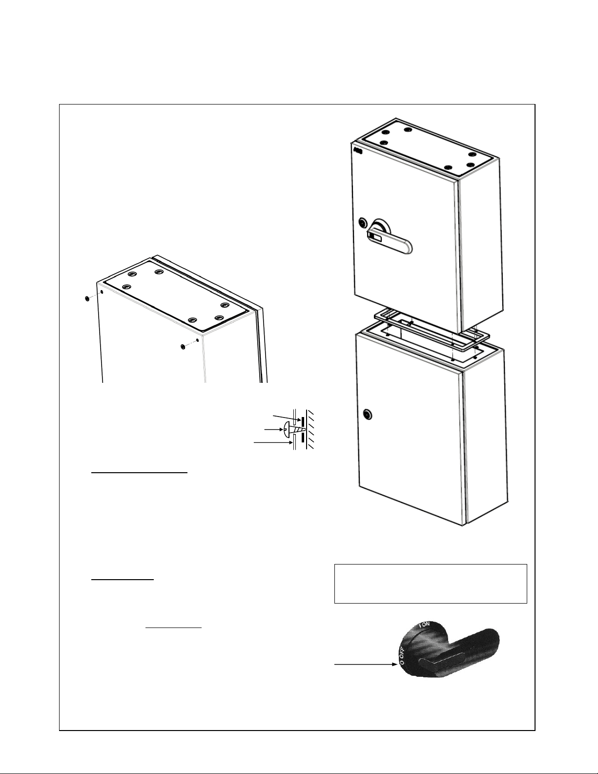
This unit should be mounted vertically
• Lids can be removed to ease installation. Lift lid vertically off
hinge pins. Ensure lid is replaced correctly.
• This product will only be IP65 when all holes are adequately
sealed.
• Use supplied washers to maintain IP rating. Position to rear
of enclosure prior to fixing to surface. (see figure 1) Use all
four washers.
• It is important that regular checks are made to all seals and
gaskets to prevent water ingress.
• Ensure all entry plate and lid fixing screws are tight.
ABB
1TVS013132P0300 30/03/11 – R1
Figure 1
Fitment of spreader boxes
• Remove bottom entry plate from switch enclosure and
reposition to the bottom of spreader box.
• Ensure all entry plate fixing screws and washers are
replaced.
• Attach supplied Mating gasket direct to top surface of
spreader box. (see figure 2)
• Remove lid and use supplied screws to connect the switch
enclosure to spreader box. Tighten screws until mating
gasket is compressed at least 50% of its thickness.
Neutral terminals
• All switch fuses are supplied with a removable link. Ensure
that the tightness of neutral link fixings is checked after
installation and at regular intervals.
IMPORTANT: Interlock defeat
Please note the door interlock is intended to stop you
opening the door with the handle in the “on” position. Even
with the handle in the “off” position you may experience
some difficulty opening the door and where this happens
simply press a thin object into the hole found on the handles
collar between the two letter “O’s” (figure 3) whilst gently
easing the door open.
Safety note: You must disconnect incoming power before
attempting this.
Sealing washer
Fixing screw
Enclosure
Figure 2
Note: Spreader enclosures only required for
OT and OS 160A and above see sheet 2
for details.
Interlock defeat
Figure 3
Page 2
OT32FP
-B
N/A N/A
OT63TPN
-B
N/A N/A
OT125TPN
-B
N/A N/A
OT125FP
-B
N/A N/A
OT315TPN
-B
GZ4020
SRN5420K
OT315FP
-B
GZ4020
SRN5420K
OS
32FP-B N/A N/A
OS
125TPN
-B
N/A N/A
OS
200FP
-B
GZ4025
SRN6425K
OS
315TPN
-B
GZ4025
SRN6425K
Council of European Communities Directives:
The products in this publication conform to relevant EEC Directives and EN Standards. Installation and use of such products m
ust be carried out by competent, properly trained
For further information please contact your ABB Technical Helpline 02476 368500
B
D
1TVS013132P0300 30/03/11 - R1
A
OT20TPN-B N/A N/A
OT20FP-B N/A N/A
OT32TPN-B N/A N/A
OT63FP-B N/A N/A
OT100TPN-B N/A N/A
OT100FP-B N/A N/A
Gasket
Spreader
Enc.
E
C
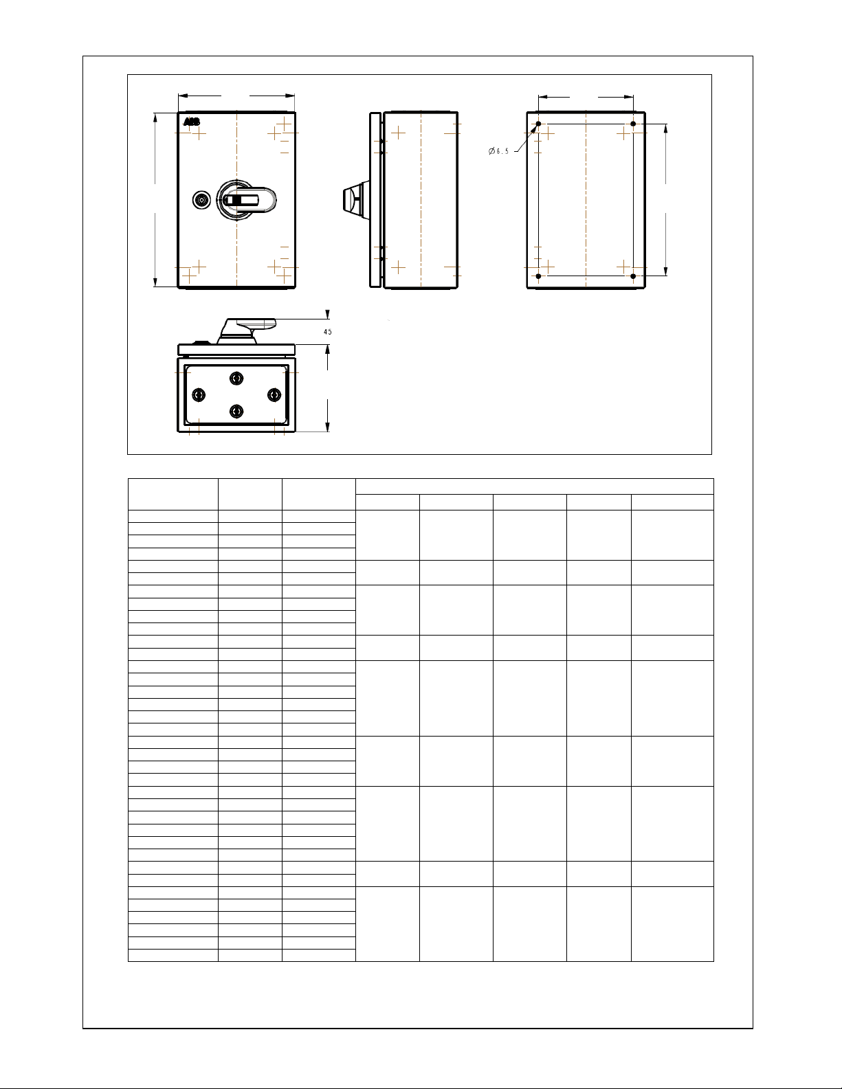
Dimensions
A B C D E
300 200 150 163 263
300 300 150 263 263
400 300 150 263 363
OT160TPN-B GZ4025 SRN5425K
OT160FP-B GZ4025 SRN5425K
OT200TPN-B GZ4020 SRN5420K
OT200FP-B GZ4020 SRN5420K
500 400 250 363 463
500 400 200 363 463
OT400TPN-B GZ4020 SRN5420K
OT400FP-B GZ4020 SRN5420K
OS20TPN-B N/A N/A
OS20FP-B N/A N/A
OS32TPN-B N/A N/A
OS63TPN-B N/A N/A
OS63FP-B N/A N/A
OS100TPN-B N/A N/A
OS100FP-B N/A N/A
OS125FP-B N/A N/A
OS160TPN-B GZ4025 SRN5425K
OS160FP-B GZ4025 SRN5425K
OS200TPN-B GZ4025 SRN6425K
OS315FP-B GZ4025 SRN6425K
OS400TPN-B GZ4025 SRN6425K
OS400FP-B GZ4025 SRN6425K
personnel, complying with any instructions supplied by ABB. Liability for improper incorporation, assembly, use, processing, storing or handling of goods remains the sole responsibility of the individual, or company carrying out
such work. This publication is for information only. Whilst every care has been taken in the preparation of this leaflet, no liability is accepted for any consequence of its use. No licence to use any patent should be assumed. All
dimensions are approximate only and subject to change without notice, as are other technical features resulting from continual development and improvement.
300 300 150 263 263
400 300 150 263 363
500 400 250 363 463
600 400 250 363 563
 Loading...