

Page 1
Data sheet
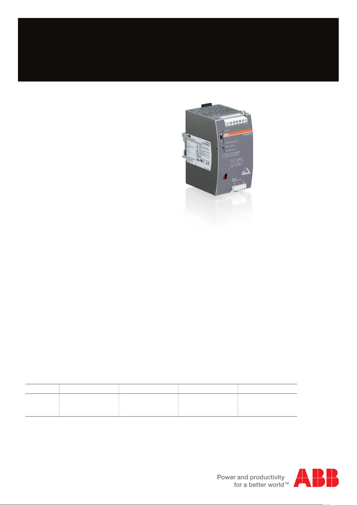
Power Supply CP-ASI/4.0
Primary switch mode power supply for AS-interface
The CP-ASI power supply range is specifically
designed with integrated data decoupling for the
supply of AS-Interface systems.
Up to 62 slaves (binary I/O devices) can be
supplied with a single two-conductor cable.
The configurable IR addressing mode allows the
easy assign of new ID addresses by means of an
external infrared programming unit.
2CDC271004S0012
Characteristics
– Rated output voltage 30.5 V DC
– Rated output current 4.0 A
– Rated output power 122 W
– Rated input voltage 115 or 230 V AC, configurable
– Infrared addressing mode
– Integrated ground fault detection
– High efficiency of up to 90 %
– Low power dissipation and low heating
– Free convection cooling (no forced cooling with
ventilators)
– Ambient temperature range during operation -10…70 °C
– Open-circuit, overload and short-circuit stable
– Integrated input fuse
– Tool-free mounting on DIN rail as well as demounting
– LEDs for the indication of operational states
Order data
Type Input voltage range Rated output voltage Rated output current Order code
CP-ASI/4.0 85-132 V AC
184-264 V AC
240-300 V DC
30.5 V DC
Approvals
A
H
1)
Approvals refer to rated input voltage U
Marks
a
4.0 A 1SVR427090R0400
UL 508, CAN/CSA C22.2 No.107.1
UL 60950-1, CAN/CSA C22.2 No. 60950-1
in
CE
1)
1)
Page 2
Functions
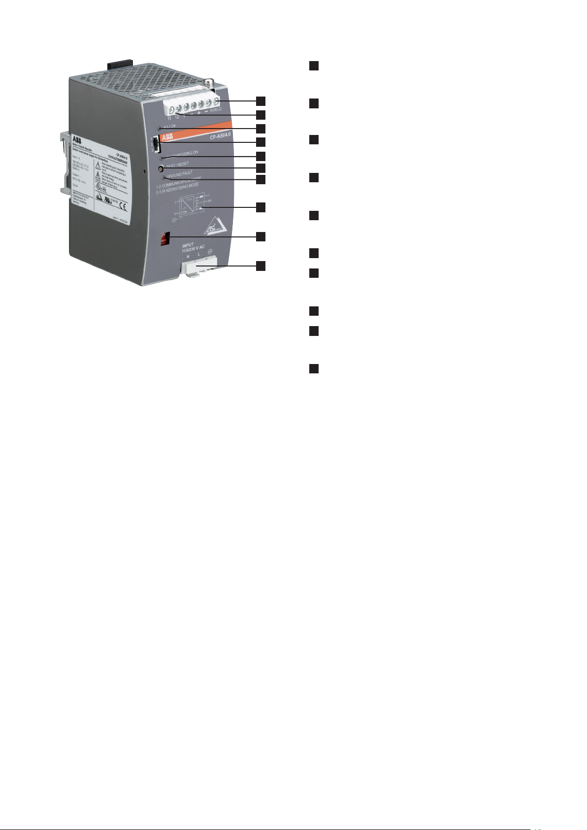
1
Output
+, -, +, -, SHIELD: output terminals
2CDC271004S0012
10
1
2
3
4
5
6
7
8
9
2
Signalling contact
11-12: ground fault signalling terminals
3
Indication of operational states
AS-I OK: green LED – output voltage OK
4
Configuration of operation mode
Jumper
5
Indication of operational states
IR ADDRESSING ON: red LED – infrared addressing mode active
6
Test and reset button
7
Indication of operational states
GROUND FAULT: red LED – ground fault detected
8
Circuit diagram
9
Input voltage selector
Adjustment of input voltage
10
Input
L, N, PE: input terminals
Application
The primary switch mode power supply is specifically designed with integrated data decoupling for the supply of ASinterface systems. To ensure a safe supply acc. to EN 60204 part 1 and DIN VDE 0113, an integrated ground fault detector
monitors the AS-interface system to prevent a machine to start inadvertently, dangereously move or to shutdown.
The power supply operates at two selectable input voltage ranges and can be used worldwide, within compact dimensions.
The easy-to-set front-face jumper allows the assignment of new ID addresses to slaves by means of an external infrared
programming unit without disconnecting them from the AS-interface cable.
Up to 62 binary I/O devices can be connected and supplied according to the AS-interface bus technology with a single
two-conductor cable. The communication signals are modulated onto the slaves’ DC supply voltage of the AS-Interface
system, which therefore requires a specific power supply with integrated data decoupling.
Operating mode
By means of the input voltage selector the input voltage can either be set to 115 V AC or 230 V AC. The front-face
jumper allows the configuration of the operation mode of the power supply, i.e. “1-2 COMMUNICATION MODE” or
“2-3IRADRESSING MODE” to either control and supply AS-interface slaves or to interrupt the data communication for the
assignment of new ID addresses to slaves by means of an external infrared programming unit.
Detected ground faults are stored and signalled. The front-face “TEST/RESET” button activates the ground fault test
function or resets the internal fault storage. For proper functioning, it is essential to connect the shield terminal to PE or
machine ground. The AS-interface network must not contain any other ground fault detectors or insulation monitoring
devices.
The green LED “AS-I OK” is on during normal operation, i.e. when the output voltage exceeds 30 V DC, and is off at
overload.
The red LED “IR ADDRESSING ON” is on when data communication has been interrupted by means of the jumper.
The red LED “GROUND FAULT” is on when a ground fault is present or has been stored.
2 - Power Supply CP-ASI/4.0 | Data sheet
Page 3
Installation
The device must be installed by qualified persons only and in accordance with the specific national regulations (e.g. VDE,
etc.). The devices are maintenance-free chassis-mounted units.
Before installation
DANGER!
Components with high stored energy and circuits with high voltage
Danger to be electrocuted!
Disconnect the system from the supply network and protect against switching on before any
installation, maintenance or modification work.
Do not introduce any objects into the unit and do not open the unit.
Ensure that the service personnel is protected against inadvertent contact with parts carrying energy.
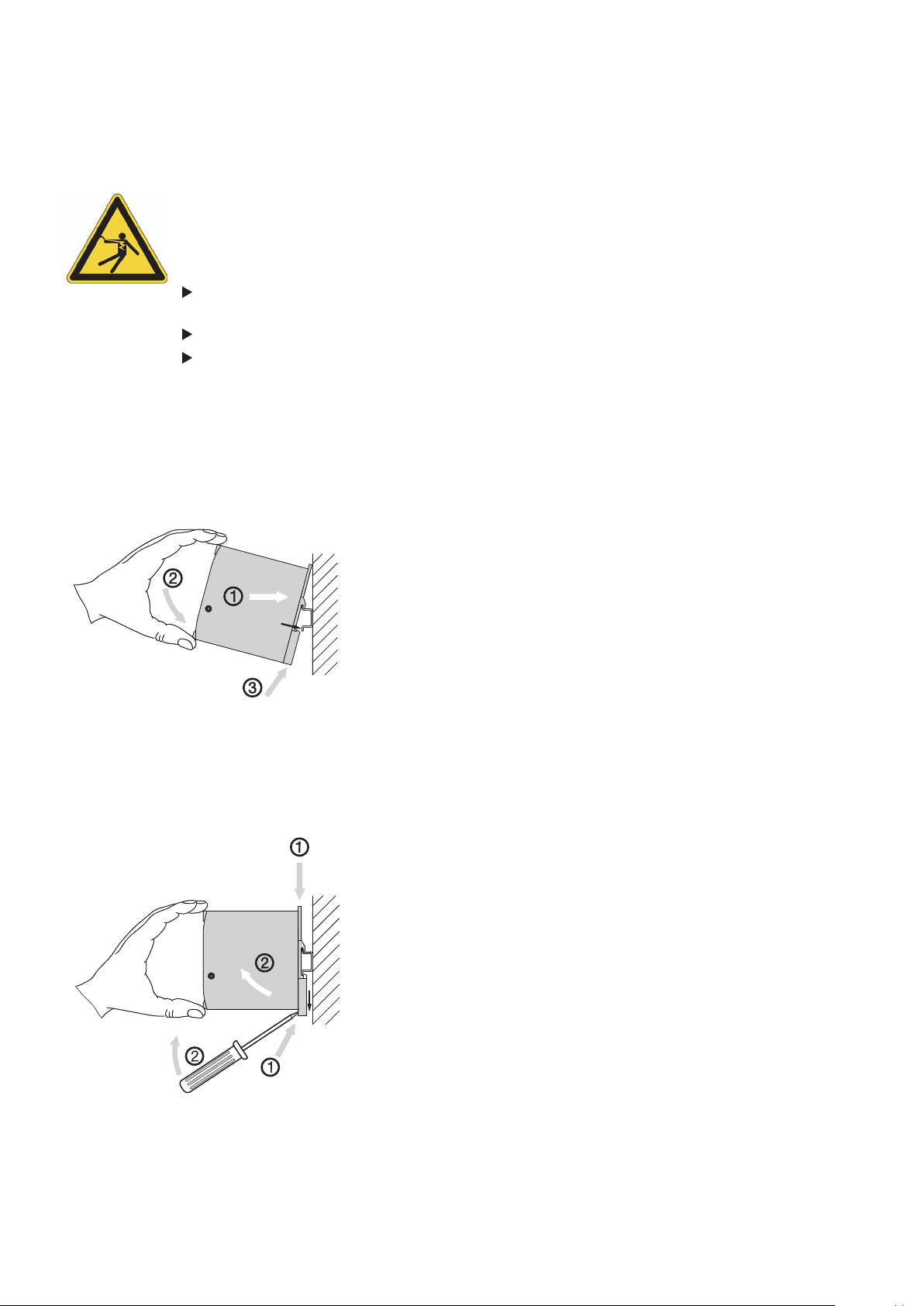
Mounting
The switch mode power supply can be snapped on a DIN rail (TH 35-15 or TH 35-7.5 according to IEC/EN 60715) as
shown in the accompanying picture. For that the device is set with its mounting rail slide on the upper edge of the mounting
rail and locked by lifting it downwards.
click
2CDC273001F0012
Demounting
Remove the switch mode power supply as shown in the accompanying picture. For that the latching lever is pulled
downwards by means of the screwdriver. Alternatively the upperside of the latching lever can be pressed to release the
device. Then in both cases the device can be unhinged from the mounting rail edge and removed.
2CDC273002F0012
Alternative:
Data sheet | Power Supply CP-ASI/4.0 - 3
Page 4
Mounting position
_
_
o
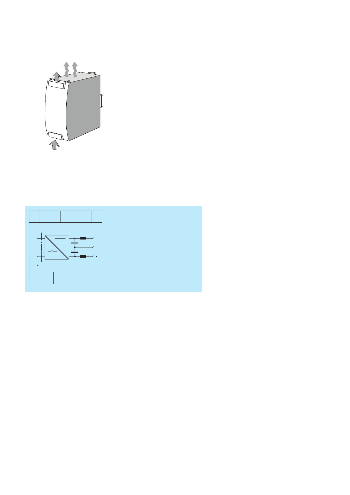
The devices have to be mounted horizontally with the input terminals on the bottom. In order to ensure a sufficient
convection, the minimum distance to other modules should not be less than 15 mm (0.59 in) in vertical and 25 mm (0.98 in)
horizontal direction.
OUT
2CDC 272 001 F0012
IN
Electrical connection
11
12
+
+
SH
+, - Output voltage
SH Shield
L, N Input voltage
11-12 Signalling contact
o Protective earth
2CDC272004F0012
o
L
PWM
N
N
L
+
SH
Preparations:
– Connect to mains according to the specific national regulations.
− Power supply cables and unit must be sufficiently fused. A disconnecting device has to be provided for the power supply
to disengage unit and supply cables from supply mains if required.
− We recommend to choose the cable section as large as possible in order to minimize voltage drops.
− In order to ensure sufficient air-cooling the distance to other devices has to be considered.
Instructions:
1. Connect the input terminals L and N.
2. Connect the protective earth conductor to terminal o (protection class I).
3. Provide a suitable disconnecting device (e.g. line protection switch) in the supply line acc. to IEC/EN 60950-1.
4. Rate the lines for the maximum output current (considering the short-circuit current) or provide a separate fuse protection.
The input side is protected by an internal input fuse.
5. Observe the polarity.
Connect the ‘shield’ terminal on the AS-i power supply to the machine ground so that the AS-i system is symmetrically
operated against this machine ground. This improves noise sensitivity in case of symmetrical interference on the AS-i cable.
The device is overload, short-circuit and open-circuit proof. The secondary side of the power supply unit is electrically
isolated from the input.
4 - Power Supply CP-ASI/4.0 | Data sheet
Page 5

Operation
DANGER!
High current
Risk of electric arcs and electric shocks!
Do not modify the installation (primary and secondary side).
Intended use.
CAUTION!
Depending on the operation conditions the enclosure can become very hot
Risk of burns!
In order to ensure sufficient air-cooling the distance to other devices has to be considered.
The device is intended for use as a primary switch mode power supply for AS-interface systems. Any other usage is not
supported by the manufacturer. Other usage may impair safety and cause operational difficulties or destruction of the unit.
Service
The internal fuse is not user-replaceable. If the internal fuse blows, most probably the device is defective. In this case, an
examination of the switch mode power supply by the manufacturer is necessary.
Data sheet | Power Supply CP-ASI/4.0 - 5
Page 6

Technical data
Data at Ta = 25 °C, Uin = 230 V AC and rated values, unless otherwise indicated
Input circuit – Supply circuit L, N
Rated input voltage U
in
Input voltage range switch position 115 V 85-132 V AC
Frequency range AC 47-63 Hz
Typical input current switch position 115 V 2.7 A
Typical power consumption 135 W
Inrush current limiting / I²t (cold start) < 44.7 A (120 V AC) / approx. 3.7 A²/s
Discharge current towards PE < 3.5 mA
Power failure buffering time at 115 V AC min. 40 ms
Transient overvoltage protection varistor
Internal input fuse 3.15 A slow acting / 250 V AC
External fusing (not necessary, but recommended) circuit breaker with C characteristic min. 6 A,
Power Factor Correction (PFC) at 115 V AC 0.58
switch position 115 V 100-120 V AC
switch position 230 V 220-240 V AC
switch position 230 V 184-264 V AC / 240-300 V DC
switch position 230 V 1.3 A
< 49.3 A (132 V AC) / approx. 4.6 A²/s
< 49.7 A (230 V AC) / approx. 2.5 A²/s
< 57.5 A (264 V AC) / approx. 3.3 A²/s
at 230 V AC min. 40 ms
or alternatively 10 A with B characteristic
at 230 V AC 0.53
Indication of operational states
Output voltage AS-I OK LED green
IR addressing mode IR ADDRESSING ON LED red
Ground fault status GROUND FAULT LED red
Output circuit +, -, 11, 12
Rated output power 122 W
Rated output voltage 30.5 V DC
Tolerance of the output voltage ± 3 %
Rated output current I
r
Ta ≤ 60 °C 4.0 A
Derating of the output current 60 °C < Ta ≤ 70 °C 2.5 % / °C
Signalling contact for ground fault 11-12 max. 25 V AC or 60 V DC, 0.5 A
Control time < 2 ms
Starting time after applying the supply voltage max. 700 ms
Rise time max. 100 ms
Residual ripple BW = 500 kHz typ. < 50 mV
Switching peaks BW = 20 MHz typ. < 150 mV
pp
pp
Output circuit – No-load, overload and short-circuit behaviour
Characteristic curve of output U/I characteristic curve
Short-circuit protection continuous short-circuit stability
Short-circuit behavior continuation with output power limiting
Current limiting at short circuit min / max 4.2 A / 6.5 A
Overload protection output power limiting
No-load protection continuous no-load stability
6 - Power Supply CP-ASI/4.0 | Data sheet
Page 7
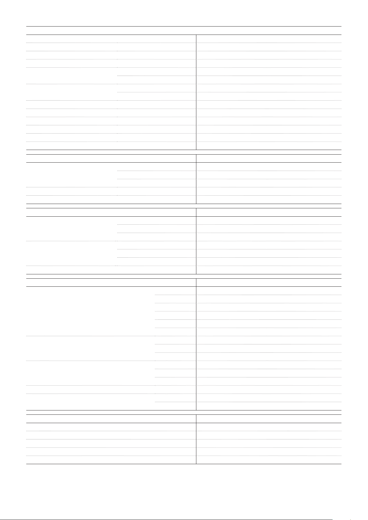
General data
MTBF on request
Power dissipation typ. < 13.5 W (230 V AC, 4.0 A)
Efficiency typ. 90 %
Duty time 100 %
Dimensions (W x H x D) product dimensions 73 x 131 x 107 mm (2.87 x 5.16 x 4.21 in)
packaging dimensions 151 x 98 x 140 mm (5.94 x 3.86 x 5.51 in)
Weight net weight 0.653 kg (1.440 lb)
gross weight 0.750 kg (1.653 lb)
Material of housing metal
Mounting DIN rail (IEC/EN 60715), snap-on mounting without any tool
Mounting position horizontal
Minimum distance to other units horizontal / vertical 15 mm / 25 mm (0.59 / 0.99 in)
Degree of protection housing / terminals IP 20
Protection class I
Electrical connection
Wire size fine-strand with wire end ferrule 0.5-4 mm² (20-12 AWG)
fine-strand without wire end ferrule 0.5-4 mm² (20-12 AWG)
rigid 0.5-6 mm² (20-10 AWG)
Stripping length 7 mm (0.28 in)
Tightening torque 0.8 Nm (7.08 lb.in)
Environmental data
Ambient temperature ranges operation -10...+70 °C
rated load -10...+60 °C
storage -25...+85 °C
Vibration 2-17.8 Hz, amplitude ± 1.6 mm
sinusoidal (IEC/EN 60068-2-6) 17.8 Hz - 500 Hz, 2 g
random (IEC 60068-2-64) 2-800 Hz 0.5 s² (s³)
Shock, half-sine (IEC/EN 60068-2-27) 15 g (6 ms), 10 g (11 ms)
Isolation data
Rated insulation voltage U
i
input / output 300 V
(IEC/EN 60950-1, EN 50178) input / PE 300 V
input / 11-12 300 V
output / PE 50 V
shield / output 50 V
shield / PE 50 V
Rated impulse withstand voltage U
imp
input / output 6 kV 1.2/50 µs
(EN 50178) input / PE 4 kV 1.2/50 µs
output / PE 500 V 1.2/50 µs
Power-frequency withstand voltage test (test voltage) input / output 2.5 kV AC / 3.0 kV AC
(routine test / type test) input / PE 2.5 kV AC / 2.5 kV AC
output / PE 500 V AC / 500 V AC
Pollution degree (IEC/EN 60950-1) 2
Overvoltage category (IEC/EN 60950-1, EN 50178) input II (IEC/EN 60950-1), III (EN 50178)
output II (IEC/EN 60950-1), II (EN 50178)
Standards / Directives
Standards IEC/EN 60950-1
Low Voltage Directive 2014/35/EU
Protective low voltage SELV (IEC/EN 60950-1), PELV
EMC Directive 2014/30/EU
RoHS Directive 2011/65/EU
Data sheet | Power Supply CP-ASI/4.0 - 7
Page 8

Electromagnetic compatibility
Interference immunity to IEC/EN 61000-6-2
electrostatic discharge IEC/EN 61000-4-2 Level 4 (8 kV / 15 kV)
radiated, radio-frequency, electromagnetic field IEC/EN 61000-4-3 Level 3 (10 V/m)
electrical fast transient/burst IEC/EN 61000-4-4 input circuit: Level 4 (4 kV)
output / signalling circuit: Level 3 (2 kV)
surge IEC/EN 61000-4-5 input circuit: L-L Level 3 (2 kV) / L-PE Level 4 (4 kV)
output circuit: Level 1 (0.5 kV)
conducted disturbances, induced by radio- IEC/EN 61000-4-6 Level 3 (10 V, 150 kHz - 80 MHz)
frequency fields
voltage dips, short interruptions and voltage
variations
Interference emission IEC/EN 61000-6-3
high-frequency radiated IEC/CISPR 22, EN 55022 Class B
high-frequency conducted IEC/CISPR 22, EN 55022 Class B
limits for harmonic current emissions IEC/EN 61000-3-2 Class A
IEC/EN 61000-4-11 Class 3
8 - Power Supply CP-ASI/4.0 | Data sheet
Page 9
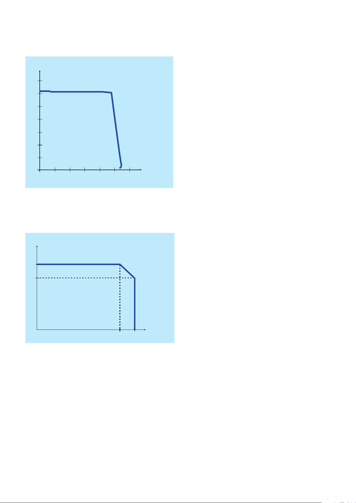
Technical diagrams
Output behaviour
U
[V]
out
35
30
25
20
15
10
5
0
01
Characteristic curve of output at Ta = 25 °C
2345
6
Temperature behaviour
I
[A]
out
4
3
2CDC272009F0012
I
[A]
out
2CDC272008F0212
-10 60 70
Characteristic curve of temperature at rated load
Ta [°C]
Data sheet | Power Supply CP-ASI/4.0 - 9
Page 10
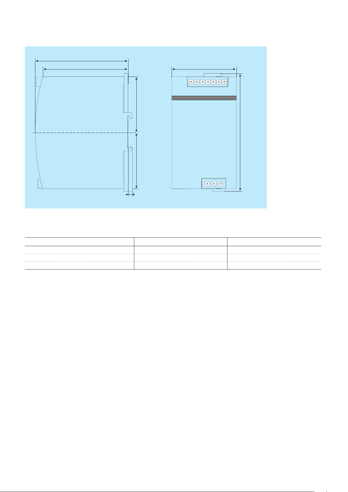
Dimensions
in mm and inches
102 4.02”
94 3.78”
73 2.87”
62 2.44”
2CDC272015F0012
131 5.16”
62 2.44”
5 0.20”
Further documentation
Document title Document type Document number
Electronic products and relays Technical catalogue 2CDC 110 004 C02xx
Power supply units Application manual 2CDC 114 048 M020x
CP-ASI/2.8, CP-ASI/4.0, CP-ASI/8.0 Instruction manual 1SVC 427 090 M0000
10 - Power Supply CP-ASI/4.0 | Data sheet
 Loading...