

Page 1
Installation Guide
Circular Chart Recorder
IM/C1900–INS_13
and Recorder/Controller
C1900 Series
Page 2
ABB
The Company
EN ISO 9001:2000
We are an established world force in the design and manufacture of instrumentation for industrial
process control, flow measurement, gas and liquid analysis and environmental applications.
As a part of ABB, a world leader in process automation technology, we offer customers
Cert. No. Q 05907
application expertise, service and support worldwide.
We are committed to teamwork, high quality manufacturing, advanced technology and unrivalled
EN 29001 (ISO 9001)
service and support.
The quality, accuracy and performance of the Company’s products result from over 100 years
experience, combined with a continuous program of innovative design and development to
Lenno, Italy – Cert. No. 9/90A
incorporate the latest technology.
The UKAS Calibration Laboratory No. 0255 is just one of the ten flow calibration plants operated
Stonehouse, U.K.
by the Company and is indicative of our dedication to quality and accuracy.
0255
Electrical Safety
This equipment complies with the requirements of CEI/IEC 61010-1:2001-2 'Safety Requirements for Electrical Equipment for
Measurement, Control and Laboratory Use'. If the equipment is used in a manner NOT specified by the Company, the protection
provided by the equipment may be impaired.
Symbols
One or more of the following symbols may appear on the equipment labelling:
Warning – Refer to the manual for instructions
Caution – Risk of electric shock
Protective earth (ground) terminal
Earth (ground) terminal
Information in this manual is intended only to assist our customers in the efficient operation of our equipment. Use of this manual for
any other purpose is specifically prohibited and its contents are not to be reproduced in full or part without prior approval of the
Technical Publications Department.
Health and Safety
To ensure that our products are safe and without risk to health, the following points must be noted:
1. The relevant sections of these instructions must be read carefully before proceeding.
2. Warning labels on containers and packages must be observed.
3. Installation, operation, maintenance and servicing must only be carried out by suitably trained personnel and in accordance with the
information given.
4. Normal safety precautions must be taken to avoid the possibility of an accident occurring when operating in conditions of high pressure and/
or temperature.
5. Chemicals must be stored away from heat, protected from temperature extremes and powders kept dry. Normal safe handling procedures
must be used.
6. When disposing of chemicals ensure that no two chemicals are mixed.
Safety advice concerning the use of the equipment described in this manual or any relevant hazard data sheets (where applicable) may be
obtained from the Company address on the back cover, together with servicing and spares information.
Direct current supply only
Alternating current supply only
Both direct and alternating current supply
The equipment is protected
through double insulation
Page 3
CONTENTS
1 INTRODUCTION
Section Page
1 INTRODUCTION ........................................................... 1
2 PREPARATION ............................................................. 2
2.1 Accessories ........................................................2
2.2 Checking the Code Number ............................... 2
2.2.1 Non-upgradeable Version...................... 2
3 MECHANICAL INSTALLATION .................................... 3
3.1 Siting .................................................................. 3
3.2 Mounting ............................................................ 3
3.2.1 Wall-/Pipe-Mounting.............................. 4
3.2.2 Panel Mounting .....................................5
4 ELECTRICAL INSTALLATION ...................................... 6
4.1 Identifying the Input/Output Modules .................. 7
4.2 Channel Connections ......................................... 7
4.2.1 Selecting the Analog Input Type(s) ......... 8
4.2.2 Voltage and Current .............................. 9
4.2.3 2-wire Transmitter Input......................... 9
4.2.4 Thermocouple ....................................... 9
4.2.5 Resistance Thermometer (RTD) ............. 9
4.2.6 Logic Inputs .......................................... 9
4.2.7 Analog Output ....................................... 9
4.2.8 Relay Output ........................................9
4.2.9 Motorized Valve................................... 10
4.3 Module Connections ......................................... 11
4.3.1 Standard I/O or Analog + Relay
(Module Types 1, 2 and 7) ...................11
4.3.2 Four Relay Module (Module Type 3)..... 11
4.3.3 Eight Digital Inputs or Outputs
(Module Types 4 and 5 respectively) .... 11
4.4 Power Supply Connections ............................... 13
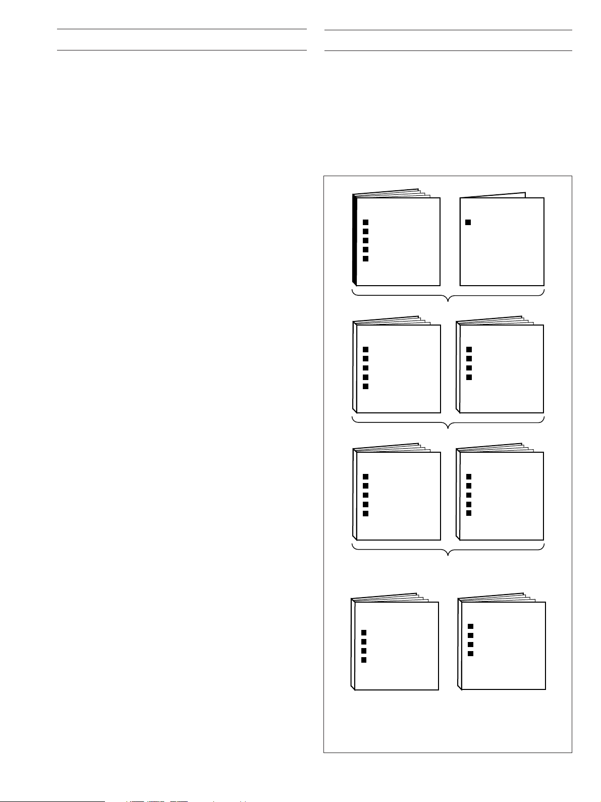
The documentation for the C1900 series of circular chart
recorders is shown in Fig. 1.1. The
Standard Manuals, including
the data sheet, are supplied with all instruments. The
Supplementary Manuals supplied depend on the specification of
the instrument.
This manual includes an Installation Record which should be
completed as a log of the electrical installation. The record is
useful when carrying out initial instrument programming and can
be retained for future reference.
INSTALLATION
Product Identification
Siting
Mounting
Electrical Connections
Installation Record
Part No.
IM/C1900–INS
Recorders and Controllers
OPERATION
Setting Up
Error Messages
Displays & Controls
Operating Level
Simple Fault Finding
Par t No.
IM/C1900–OGR
Recorders Only
DATA SHEET
Full Specification
Par t No.
SS C1900
PROGRAMMING
General Programming
Basic Config. Level
Advanced Config. Level
Connections & Links
Par t No.
IM/C1900–PGR
5 INSTALLATION RECORD ...........................................13
OPERATION
Setting Up
Error Messages
Displays & Controls
Operating Level
Simple Fault Finding
Par t No.
IM/C1900–OGC
Controllers Only
A – Standard Manuals
ADVANCED SOFTWARE
OPTIONS
Flow Totalization
Ramp/Soak Profile
Math Functions
Timer Functions
Par t No.
IM/C1900–ADV
B – Supplementary Manuals
Fig. 1.1 C1900 Documentation
PROGRAMMING
General Programming
Basic Config. Level
Control Config. Level
Advanced Config. Level
Connections & Links
Par t No.
IM/C1900–PGC
MODBUS (RTU)
Serial Adaptors
Serial Connections
Programming Pages
ASCII Tables
Par t No.
IM/C1900–MOD
1
Page 4
2 PREPARATION
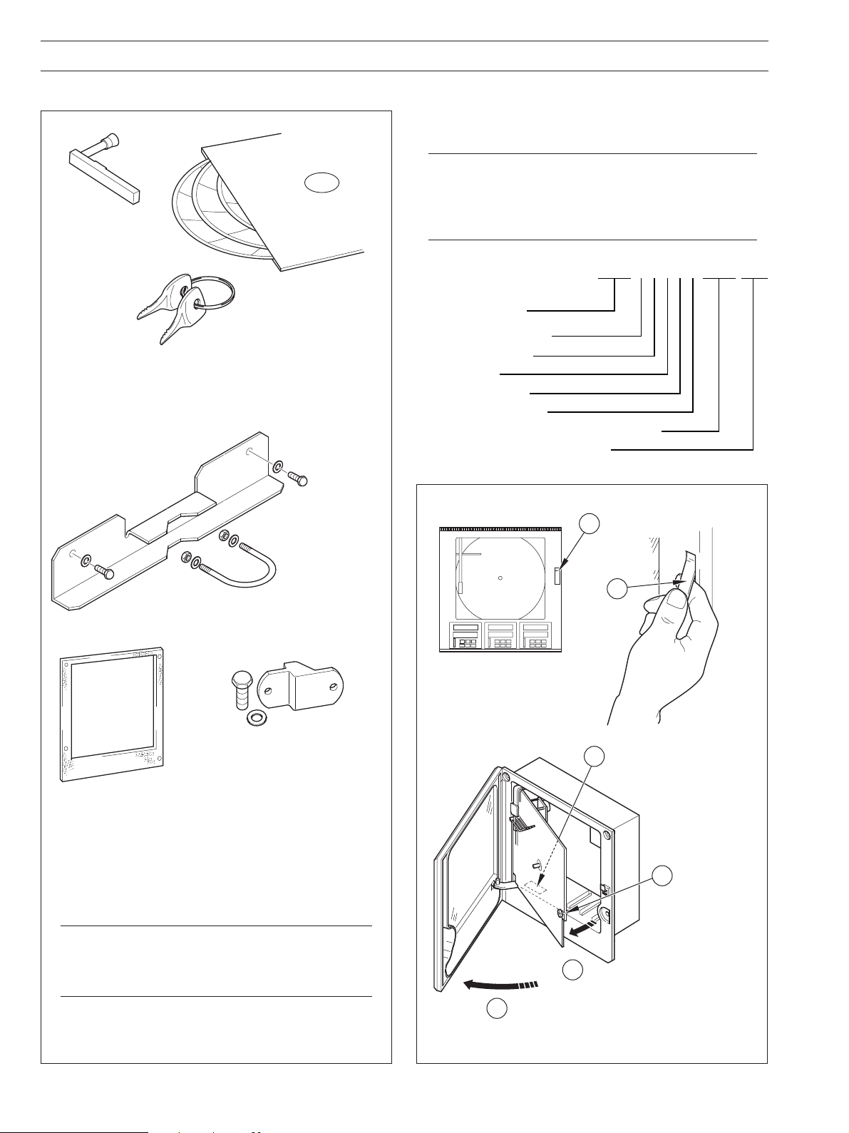
2.1 Accessories – Fig. 2.1 2.2 Checking the Code Number – Fig. 2.2
2.2.1 Non-upgradeable Version
Note. The 1901J is a basic, non-upgradeable single
pen recorder. This version is not fitted with an analog
output, relay, transmitter power supply unit or digital
Pen Capsule
1 to 4
(depending on
no. of channels)
Charts
(Pack of 3)
Keys
(door lock versions only)
A – Standard Accessories
(kit contains 2 sets
of items shown)
inputs and no additional modules can be fitted. The full
identification code is shown below.
1901J A 0 0 1 1 00000 STD
C1900
single pen recorder
Electrical code – standard
Option module – none
Options – none
Door lock – not fitted
Power supply – 115V AC
Modules fitted in module positions 2 to 6 – none
Special Settings – company standard
Case-to-Panel Gasket
C1900/0149
(see
Note below)
B – Optional Accessories
Pipe-mounting Kit
C1900/1713
Wall-mounting Kit
C1900/1712
(kit contains 4 sets
of items shown)
1
release handle
Pull handle
to release
door...
6
Push to
2
Check code number against
the Data Sheet –
SS/C1900R or SS/C1900RC
4
Loosen
captive screw
Note. If panel-mounting to NEMA 4X standard is
required, a continuous bead of suitable silicon
sealant must be applied between the case flange
and the panel. Do not use the optional gasket.
Fig. 2.1 Accessories
2
Swing chart plate forward
5
...and open door
3
Fig. 2.2 Checking the Code Number
Page 5
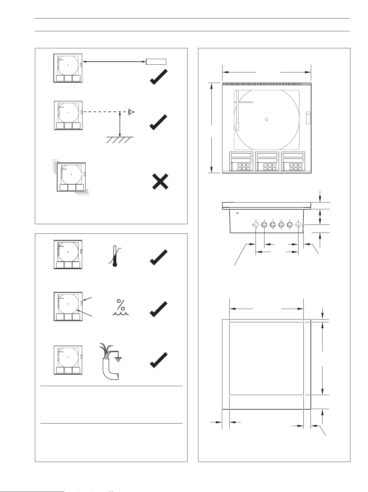
12.63 (320.8)
12.63
( 320.8)
0.32 (8.3)
2.23
(56.8)
1.18 (30.1)
1.18 (30.1)
Dimensions in inches (mm)
2.60 (66)
1.38 (35.1)
0.94 (22.4)
7.22
(183.4)
1.44 (36.6) – Typical Space Between
Adjacent Knockout Centers
1.30 (33)
15.23
(386.8)
15.04 (382)
3 MECHANICAL INSTALLATION
3.1 Siting – Figs 3.1 and 3.2 3.2 Mounting – Figs. 3.3 to 3.5
Minimum
A – Close to Sensor
B – At Eye-level Location
C – Avoid Vibration
Fig. 3.1 General Requirements
Sensor
A – Within Temperature Limits
B – Within Humidity Limits
Caution. Select a location away from strong electrical
and magnetic fields. If this is not possible, particularly in
applications where mobile communications equipment
is expected to be used, screened cables within earthed
(grounded) metal conduit must be used.
0°C
(32°F)
Min.
0 to 95% RH
0 to 80% RH
+
55°C
(131°F)
Max.
C – Use Screened Cables
Fig. 3.2 Environmental Requirements Fig. 3.3 Overall Dimensions
3
Page 6
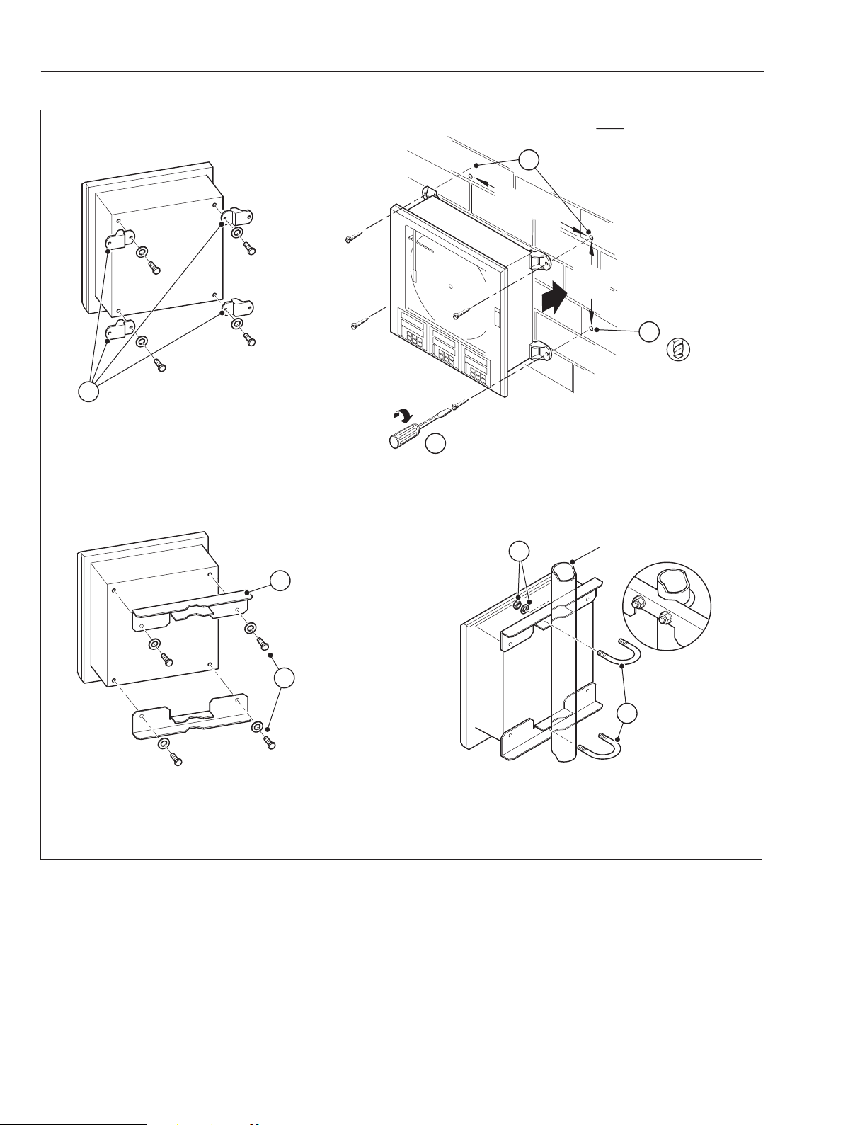
…3 MECHANICAL INSTALLATION
3.2.1 Wall-/Pipe-Mounting – Fig. 3.4
1
Secure mounting
brackets (4) to case
14.81 (376.3)
Secure instrument to
4
wall using suitable fixings
2
Mark fixing centers on wall (4)
11.06
(281.0)
Drill suitable
holes (4)
3
A – Wall-mounting (Optional)
Position mounting
1
brackets to suit horizontal
pipe-mounting or vertical
pipe-mounting as required
Secure mounting
2
brackets to case using
bolts and washers
B – Pipe-Mounting (Optional)
Fig. 3.4 Wall-/Pipe Mounting
Secure using
two nuts and
washers
3
/8 in. (60mm) OD
2
4
horizontal or vertical pipe
Fit 'U' bolts
3
into brackets
4
Page 7
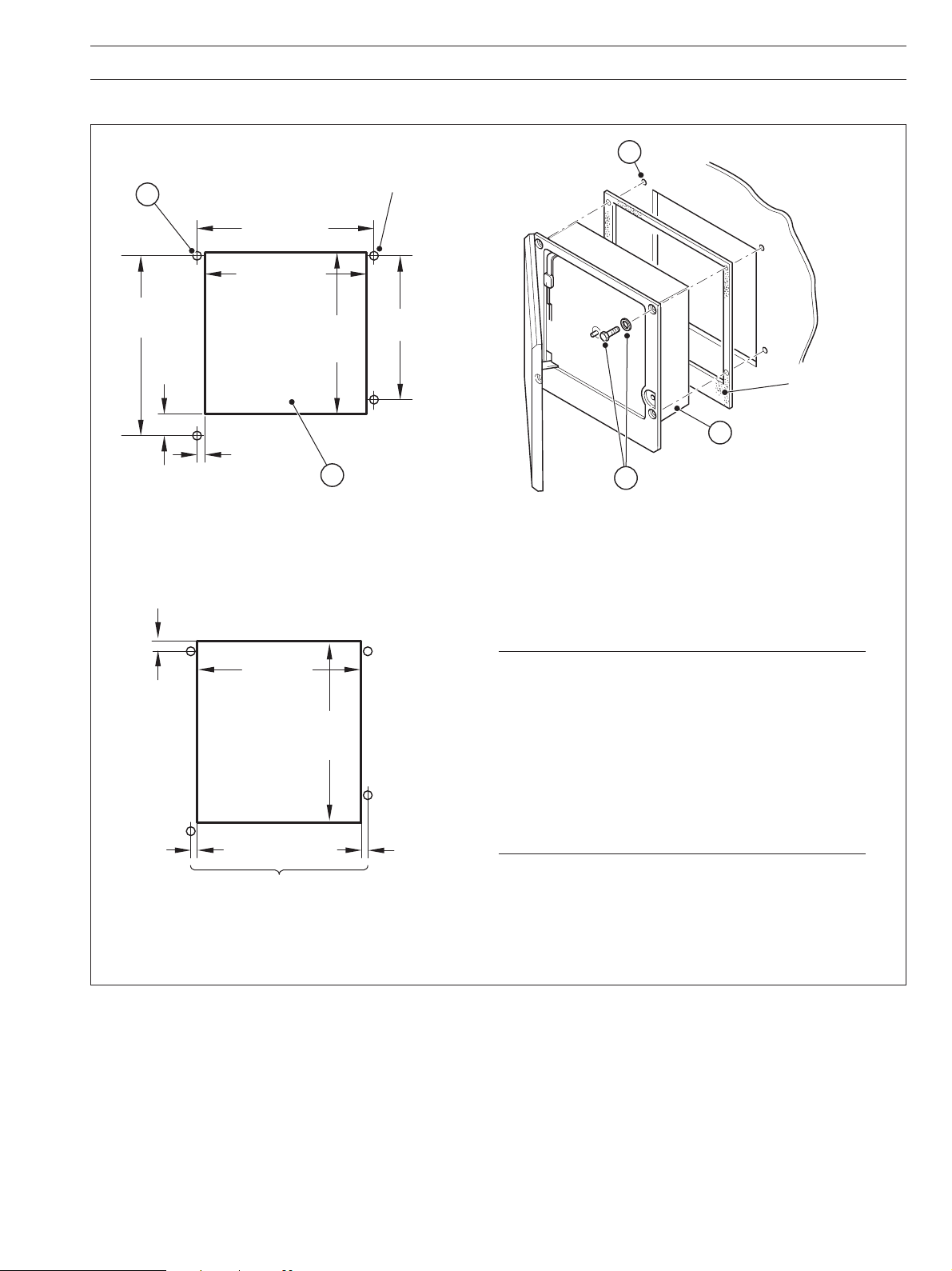
3.2.2 Panel Mounting – Fig. 3.5
3 MECHANICAL INSTALLATION
Dimensions in inches (mm)
Mark four mounting holes
2
14.00 (355.6)
12.72 (323.08)
minimum
14.19
(360.4)
1.70
(43.2)
0.64 (16.25)
Minimum Cut-out Dimensions
0.20
(5.0)
4 holes 0.281 dia.
or tap for
12.72
(323.1)
minimum
1
Cut hole in panel
Note 1
(see
1
/4 in. thread
11.25
(285.8)
below)
Drill four suitable holes
3
Locate instrument
4
in cut-out
Secure in panel using
5
four bolts, washers and nuts
Optional gasket
(see
Note 2
below)
0.15 (3.8)
minimum
13.7 (348.0)
maximum
14.6
(371.0)
maximum
Ensure cut-out positioned centrally
between mounting holes
Maximum Cut-out Dimensions
Notes.
1. The instrument can be inserted into a panel cut-out
2. If panel-mounting to NEMA 4X hosedown standard
0.15 (3.8)
minimum
Fig. 3.5 Panel Mounting
of any size between the minimum and maximum
dimensions illustrated, provided the cut-out is
positioned centrally relative to the fixing holes. If the
panel cut-out is larger than the maximum, a locally
manufactured adaptor plate will be required.
is required, a continuous bead of suitable silicon
sealant must be applied beween the case flange
and the panel. Do not use the optional gasket.
5
Page 8
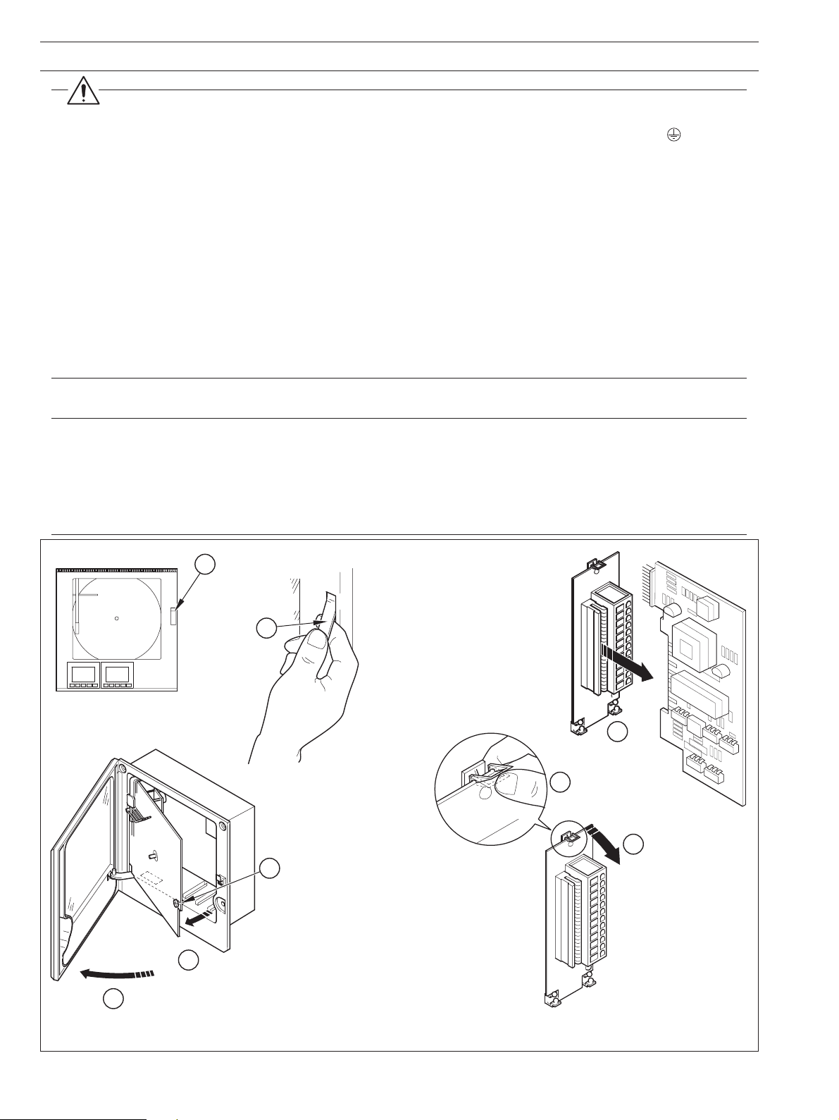
4 ELECTRICAL INSTALLATION
Warnings.
•To comply with Underwriter Laboratories (UL) and Canadian Standards Association (CSA) certification, route signal leads
and power cables in earthed (grounded), flexible metal conduit. Use the Position 1 protective ground stud
terminal module ground stud) to ground the flexible metal conduit.
• Instruments not fitted with the optional internal on/off switch and fuse must have a disconnecting device such as a switch
or circuit breaker conforming to local safety standards fitted to the final installation. It must be fitted in close proximity to
the instrument within easy reach of the operator and must be marked clearly as the disconnection device for the
instrument.
• Remove all power from supply, relay and any powered control circuits and high common mode voltages before accessing
or making any connections.
• Use cable appropriate for the load currents. The terminals accept cables up to 14AWG (2.5mm
• The instrument and all inputs and outputs conform to Mains Power Input Insulation Category II.
• All connections to secondary circuits must have basic insulation.
• After installation, there must be no access to live parts e.g. terminals.
•Terminals for external circuits are for use only with equipment with no accessible live parts.
• If the instrument is used in a manner not specified by the Company, the protection provided by the equipment may be
impaired.
• All equipment connected to the instrument’s terminals must comply with local safety standards (IEC 60950, EN601010-1).
Notes.
• Always route signal leads and power cables separately.
• Use screened cable for signal inputs and relay connections. Connect the screen to the earth (ground) stud – see Fig. 4.10.
• The terminal blocks can be removed from the main PCB when making connections – see Fig. 4.1. Before removing a
module, note its position.
• If wall- or pipe-mounting to NEMA 4X hosedown standard is required, suitable cable glands must be used to prevent
water ingress.
2
).
(NOT the
Push to
1
release handle
Pull handle
to release
2
door...
4
Loosen
captive screw
Swing chart plate forward
5
7
6
Unplug
Module
Release
Clip
8
Remove Terminal
Block Assembly
...and open door
3
Fig. 4.1 Removing Terminal Block Assembly
6
Page 9

2 3 4 5 6
Additional
Functions
Additional
Functions
Channel 2
(Green Pen)
Channel 3
(Blue Pen)
Module
Positions
2 3 4 5 6
Channel 4
(Black Pen, Violet Event
Pen or Additional Functions)
See
Note
Below
Channel 1
(Red Pen)
Not available on
non-upgradeable
version
4.1 Identifying the Input/Output Modules – Fig. 4.2
To gain access to the modules, open the door and chassis – see
Fig. 2.2. There are six module positions as shown in
Fig. 4.2.
4.2 Channel Connections
Channel 1 connections are made directly to the terminal block
mounted on the motherboard.
Other Channel connections are made to standard I/O modules,
fitted in positions 2, 3 or 4 – see Fig. 4.2.
Warning. The maximum channel to channel
voltage (between any 2 channels) must not exceed
500V DC.
4 ELECTRICAL INSTALLATION…
Notes.
• Module positions can also be used for
additional I/O modules (module types 1 and
2) for use with math functions.
• The module type is marked on the
component side of the PCB.
Fig. 4.2 Module Positions and Functions
7
Page 10

…4 ELECTRICAL INSTALLATION
4.2.1 Selecting the Analog Input Type(s) – Figs. 4.3 and 4.4
Plug-in links are used to select the input type:
Channel 1 PL1 & PL8 on the main p.c.b. (Fig. 4.3)
Channels 2 to 4 PL1 & PL3 on the module (Fig. 4.4)
5
PL1
8
mV THC
4
1
5
PL1
8
mA V RTD & Resistance
PL8PL8
1
2
4
3
1
2
2-wire Transmitter All Other Input Types
Fig. 4.3 Selecting the Input Type (Main Board)
PL3 PL3
3
4
2-wire Transmitter
41
2
1
3
4
2
1
All Other Input Types
41
R50
R44
C110
PL1
54
8
1
C18
41
23
PL8
C122
+
R53
C12
+
C13
C25
L14
L11
TRA9
TR9
L17
2 3 4 5 6
C83
C117
+
STAR
DJ4 IC19
C104
IC6
TR6
+
C119
L22
R64
JC50
C126
D15
IC5
4
1
4
3
R56
C33
C17
C16
R21
C34
R26
R30
R24
C27
C23
C15
R44
C22
C35
C13
C10
PL3
4
C24
C26
C29
C19
C20
C21
C30
IC20
R36
R27
C14
PL1
R22
C25
R25
C38
L5
INPUT/OUTPUT MODULE
58
PL1 PL1
58
mA V RTD & ResistancemV THC
Fig. 4.4 Selecting the Input Type (I/O Modules)
elbaCgnitasnepmoC
3481SB1.69CMISNA41734NID03.oNtraP7394SB
elpuocomrehTfoepyT+–esaC+– esaC+–esaC+– esaC
)K(lA-iN/rC-iNnworBeulBdeRwolleYdeRwolleYdeRneerGneerGneerGetihW*neerG
)E(iN-uC/rC-iN———teloiVetihW*teloiV
)N(lisiN/lisirciNegnarOeulBegnarOegnarOdeRegnarO—kniPetihWkniP
)SdnaR(hR-tP/tPetihWeulBneerGkcalBdeRneerGdeRetihWetihWegnarOetihW*egnarO
)B(hR-tP/hR-tP———yerGetihW*yerG
)T(iN-uC/uCetihWeulBeulBeulBdeReulBdeRnworBnworBnworBetihW*nworB
)J(noC/eFwolleYeulBkcalBetihWdeRkcalBdeReulBeulBkcalBetihW*kcalB
)01734NID(noC/eF——
deR/eulBeulBeulB
01734NID
Table 4.1 Thermocouple Compensating Cable
stiucricefasyllacisnirtnirofeulBesaC*
—
8
Page 11
4 ELECTRICAL INSTALLATION…
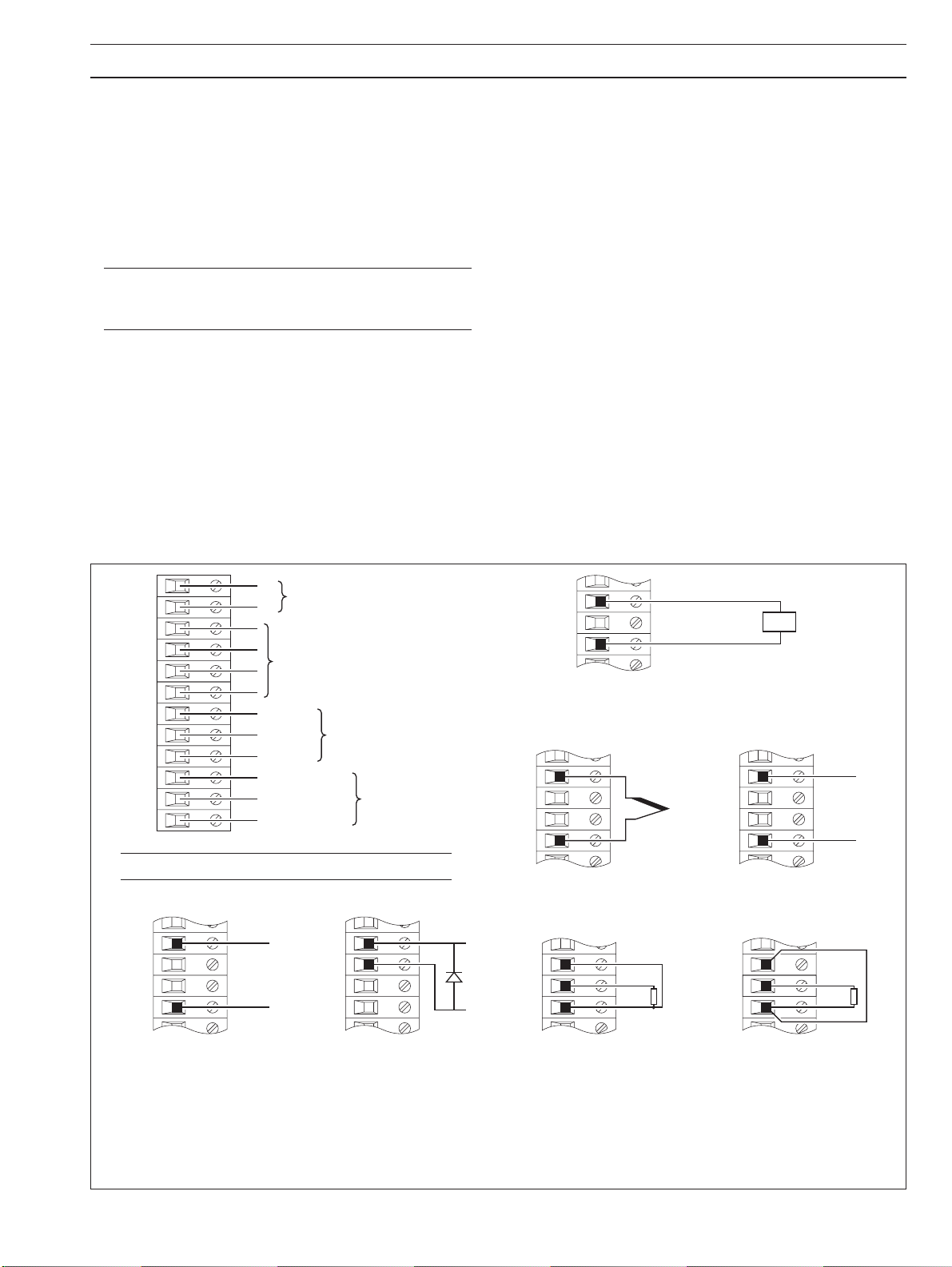
4.2.2 Voltage and Current – Fig. 4.5
Input impedances:
Low voltage (mV) >10M
Voltage >10M
Current (mA) 100
4.2.3 2-wire Transmitter Input – Fig. 4.5
Power for the transmitter is supplied by terminal 6.
Note. The voltage across terminals 4 and 6 is 20V
(nominal). This is due to internal voltage drops across a
shunt resistor and measurement circuitry.
4.2.4 Thermocouple – Fig. 4.5
Use correct compensating cable between the thermocouple
and the terminals – see Table 4.1 (previous page).
Automatic cold junction (ACJC) is incorporated but an
independent cold (reference) junction may be used.
4.2.5 Resistance Thermometer (RTD) – Fig. 4.5
If long leads are necessary it is preferable to use a 3-lead
resistance thermometer.
If 2-lead resistance thermometers are used each input must be
calibrated to take account of the lead resistance.
4.2.6 Logic Inputs – Fig. 4.5
The two logic inputs accept either volt-free (switch) or TTL (5V)
input types and can be used for remote switching of many
recorder functions, e.g. chart stop/go, alarm acknowledgment,
totalizer reset etc. Refer to the
Programming Guide,
IM/C1900–PGR or IM/C1900–PGC.
4.2.7 Analog Output – Fig. 4.5
4.2.8 Relay Output – Fig. 4.5
Relay specification:
Type single pole changeover
Voltage 250V AC 250V DC
Current 5A AC 5A DC
Loading (non inductive) 1250VA 50W
Isolation, contacts to earth 2kV RMS
1
2
3
4
5
6
7
8
9
10
1
12
+
Analog Output (See
Analog Input see B to H
Common
Logic 1
Logic 2
Normally Open
Common
Normally Closed
Logic Inputs (See
Relay Output
Note. Not applicable on Type 2 Modules.
A Summary of Connections
3
6
+
3
4
Note
below)
Note
below)
+
4
6
+
D 2-wire Transmitter
(not available on non-upgradeable version)
3
+
6
E Thermocouple
4
5
6
Red
White
Red
See
Tx
Note
+
3
6
F Low Voltage (mV)
Link
4
5
6
White
Red
below
+
B Voltage
* Recommended diode:
Diode forward voltage > 0.8 V @ 20 mA or use 2 x 1N4001 general purpose diodes in series
C Current
(non 2-wire transmitters)
Fig. 4.5 Channel Connections
G 3-wire RTD
H 2-wire RTD & Resistance
*
9
Page 12

…4 ELECTRICAL INSTALLATION
4.2.9 Motorized Valve – Fig. 4.6
A motorized valve with or without feedback requires 2 relays (common and normally open terminals) to drive the valve in either
direction. Any two relays can be allocated for this function. Fig. 4.6 A shows two possible combinations.
Note. For valves with position feedback using low voltage (mV),
voltage (V) or current (C), refer to Fig. 4.5 B, C and F for connections.
(L)
10
1st
11
Module
10
2nd
11
Module
Type 1 and/or Type 2
Modules (see
Type 1 or Type 2
Module
Four Relay Module
2
3
4
5
6
Note 1
below)
Valve
Positioner
Power
Supply
100%
0%
Motorized
Valve Drive
L
N
(N)
Motorized
Valve Drive
Type 1 or Type 2
Module
4
5
Module
6
1st or 2nd
(see
Note 2
Link
below)
0%
100%
4
5
Module
6
1st or 2nd
(see
Note 2
Link
below)
0%
100%
A – Standard Feedback Slidewire Configuration B – Alternative Feedback Slidewire Configuration
Notes.
1 Type 1 and type 2 modules have one relay output, therefore two modules are required.
2 Link must be connected at valve drive end, not at the controller terminals.
Fig 4.6 Motorized Valve Connections (using feedback slidewire)
10
Page 13

1
2
7
8
9
10
11
12
3
4
5
6
Common
Input 1
Common
Input 7
Input 8
Input
Connections
Input 5
Input 6
Input 3
Input 4
Input 2
Common
Output 1
Common
Output 7
Output 8
Output
Connections
Output 5
Output 6
Output 3
Output 4
Output 2
or
4 ELECTRICAL INSTALLATION…
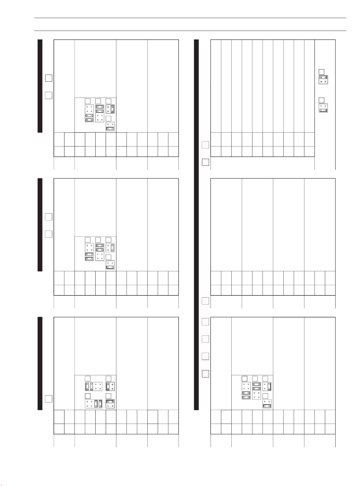
4.3 Module Connections
4.3.1 Standard I/O or Analog + Relay
(Module Types 1, 2 and 7) – Fig. 4.5
The connections are the same as Channel connections to the
main board. Refer to Section 4.2.
4.3.2 Four Relay Module (Module Type 3) – Fig. 4.7
1
2
3
4
5
6
7
8
9
10
11
12
Normally Closed
Normally Open
Common
Normally Closed
Normally Open
Common
Normally Closed
Normally Open
Common
Normally Closed
Normally Open
Common
Relay 1
Relay 2
Relay 3
Relay 4
4.3.3 Eight Digital Inputs or Outputs
(Module Types 4 and 5 respectively) –
Figs. 4.8 and 4.9
A plug-in link is used to select the board's function; digital inputs
or digital outputs – see Fig. 4.8. The maximum current drain from
each TTL output must not exceed 5mA.
PL2
14
PL2 PL2
3
4
Digital Inputs
2
1
Digital Outputs
3
4
2
1
Fig. 4.7 Four Relay Module Connections
(Module Type 3)
Fig. 4.8 Selecting the Digital Module Function
(Module Types 4 and 5)
Fig. 4.9 Eight Digital Inputs or Outputs Connections
(Module Types 4 and 5)
11
Page 14

…4 ELECTRICAL INSTALLATION
4.4 Power Supply Connections – Fig. 4.10
2 3 4 5 6
Power Switch (Optional)
Fuse (Optional)
– see Note 1 below
Note. Recorders manufactured before June 2005 are
fitted with a Mainboard that is not equipped with a
universal power supply. Ensure the supply voltage
selector switch is set correctly and the appropriate fuse
is fitted – see Fig 4.11.
1 or 4
X
Code Label
1 9 x x x x x x x x x x x x x x
Digit 10
3 or 6
Selector not Fitted
(24V AC Version)
2 or 5
115
230
Line
Neutral
Remove Plug, Connect
Earth (Ground) Stud –
see Note 2 below
Power Supply Leads to
Plug and Refit Plug
Warning. If the optional internal power
switch and fuse are not fitted, an external
disconnection device and fuse must be
fitted – see also Warnings on page 6.
Line
Neutral
Before making any electrical connections,
see Warnings on page 6
Notes.
1. Fuse rating:
500mA (20 X 5mm) Type T
2. Ensure that the Earth (Ground) lead is longer than
the Line and Neutral leads.
Position 1
Position2Position3Position4Position5Position
6
Fuse (Optional)
– see Note below
Note. Fuse ratings:
115V Supply 1A (20 x 5mm) Type T
1
230V Supply
/2A (20 x 5mm) Type T
24V Supply 4A (20 x 5mm) Type T
Fig. 4.11 Power Supply Selection
(Recorders Manufactured Before June 2005 Only)
115
12
Fig. 4.10 Power Supply Connections
Page 15
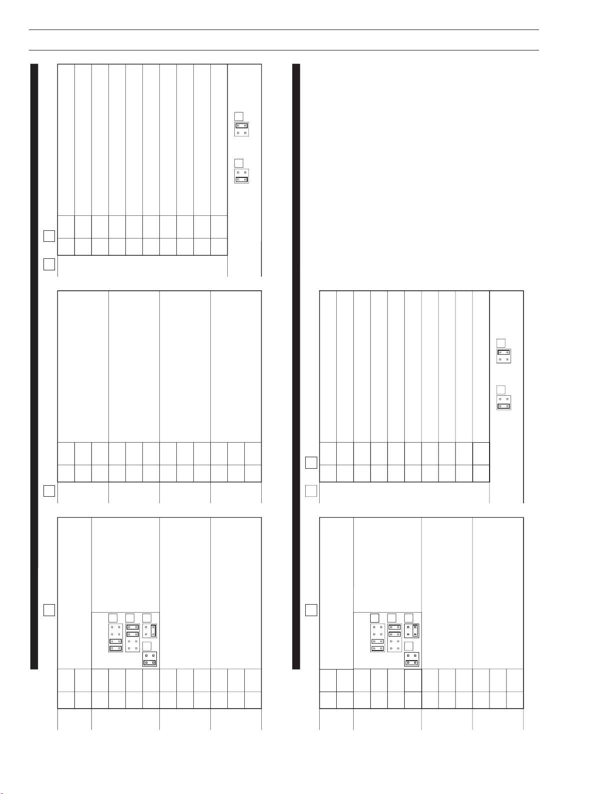
**
*
Link Positions
Module Type (Tick Box)Module Type
NC
1
Analog
Output
Analog
Input
Logic
Inputs
Relay
Output
+
2
–
3
4
5
6
7
C
8
L1
9
L2
10
NO
1
C
12
1
NC
1
Analog
Output
Analog
Input
Logic
Inputs
Relay
Output
+
2
–
3
4
5
6
7
C
8
L1
9
L2
10
NO
1
C
12
NC
1
Analog
Output
Analog
Input
Logic
Inputs
Relay
Output
+
2
–
3
4
5
6
7
C
8
L1
9
L2
10
NO
1
C
12
*
*
*
*
**
Not applicable on Module Type 2 Not applicable on Module Type 2
C
1
Relay
Output 1
Relay
Output 2
Relay
Output 3
Relay
Output 4
2
3
4
5
6
7
8
9
10
NC
1
NO
12
1
Logic I/Ps (Type 4) or Logic O/Ps (Type 5)
C
2
1
3
4
5
6
7
6
8
7
9
8
10
C
Position 1
1
2
Module Type (Tick Box)
1
2
6
7
Position 2 Position 3
1
Position 4
NC
1
Analog
Output
Analog
Input
Logic
Inputs
Relay
Output
+
2
–
3
4
5
6
7
C
8
L1
9
L2
10
NO
1
C
12
*
*
*
Not available on Module Type 2
3
4
5
C
NC
NO
C
NC
NO
C
NC
NO
2
3
4
5
Link Positions
(Tick Boxes)
Module Type (Tick Box)
(Tick Box)
Type 4 Type 5
Link Positions
(Tick Boxes)
2
Link Positions
(Tick Boxes)
Link Positions
(Tick Boxes)
5 INSTALLATION RECORD
13
Page 16
*
*
Link Positions
1
Logic I/Ps (Type 4) or Logic O/Ps (Type 5)
C
2
1
3
4
5
6
7
6
8
7
9
8
10
C
Module Type (Tick Box)
2
Position 6
NC
1
Analog
Output
Analog
Input
Logic
Inputs
Relay
Output
+
2
–
3
4
5
6
7
C
8
L1
9
L2
10
NO
1
C
12
*
*
*
Not available on Module Type 2
4
5
2
3
4
5
(Tick Box)
Type 4 Type 5
Link Positions
(Tick Boxes)
Link Positions
C
1
Relay
Output 1
Relay
Output 2
Relay
Output 3
Relay
Output 4
2
3
4
5
6
7
8
9
10
NC
1
NO
12
1
Logic I/Ps (Type 4) or Logic O?ps (Type 5)
C
2
1
3
4
5
6
7
6
8
7
9
8
10
C
Module Type (Tick Box)
2
Position 5
NC
1
Analog
Output
Analog
Input
Logic
Inputs
Relay
Output
+
2
–
3
4
5
6
7
C
8
L1
9
L2
10
NO
1
C
12
*
*
*
Not available on Module Type 2
3
4
5
C
NC
NO
C
NC
NO
C
NC
NO
2
3
4
5
(Tick Box)
Type 4 Type 5
Link Positions
(Tick Boxes)
…5 INSTALLATION RECORD
14
Page 17

NOTES
15
Page 18

…NOTES
16
Page 19

PRODUCTS & CUSTOMER SUPPORT
Products
Automation Systems
• for the following industries:
– Chemical & Pharmaceutical
– Food & Beverage
– Manufacturing
– Metals and Minerals
– Oil, Gas & Petrochemical
– Pulp and Paper
Drives and Motors
• AC and DC Drives, AC and DC Machines, AC Motors to 1kV
• Drive Systems
• Force Measurement
• Servo Drives
Controllers & Recorders
• Single and Multi-loop Controllers
• Circular Chart and Strip Chart Recorders
• Paperless Recorders
• Process Indicators
Flexible Automation
• Industrial Robots and Robot Systems
Customer Support
We provide a comprehensive after sales service via a Worldwide
Service Organization. Contact one of the following offices for
details on your nearest Service and Repair Centre.
United Kingdom
ABB Limited
Tel: +44 (0)1480 475321
Fax: +44 (0)1480 217948
United States of America
ABB Inc.
Tel: +1 215 674 6000
Fax: +1 215 674 7183
Flow Measurement
• Electromagnetic Flowmeters
• Mass Flow Meters
• Turbine Flowmeters
• Flow Elements
Marine Systems & Turbochargers
• Electrical Systems
• Marine Equipment
• Offshore Retrofit and Refurbishment
Process Analytics
• Process Gas Analysis
• Systems Integration
Transmitters
• Pressure
• Temperature
• Level
• Interface Modules
Valves, Actuators and Positioners
• Control Valves
• Actuators
• Positioners
Water, Gas & Industrial Analytics Instrumentation
• pH, Conductivity, and Dissolved Oxygen Transmitters and
Sensors
• Ammonia, Nitrate, Phosphate, Silica, Sodium, Chloride,
Fluoride, Dissolved Oxygen and Hydrazine Analyzers.
• Zirconia Oxygen Analyzers, Katharometers, Hydrogen Purity
and Purge-gas Monitors, Thermal Conductivity.
Client Warranty
Prior to installation, the equipment referred to in this manual must
be stored in a clean, dry environment, in accordance with the
Company's published specification.
Periodic checks must be made on the equipment's condition. In
the event of a failure under warranty, the following documentation
must be provided as substantiation:
1. A listing evidencing process operation and alarm logs at time of
failure.
2. Copies of all storage, installation, operating and maintenance
records relating to the alleged faulty unit.
Page 20

ABB has Sales & Customer Support
expertise in over 100 countries worldwide
www.abb.com
The Company’s policy is one of continuous product
improvement and the right is reserved to modify the
information contained herein without notice.
Printed in UK (10.08)
© ABB 2008
IM/C1900–INS Issue 13
ABB Limited
Howard Road, St Neots
Cambridgeshire
PE19 8EU
UK
Tel: +44 (0)1480 475321
Fax: +44 (0)1480 217948
ABB Inc.
125 E. County Line Road
Warminster
PA 18974
USA
Tel: +1 215 674 6000
Fax: +1 215 674 7183
 Loading...