

Page 1
—
ABB MEASUREMENT & ANALYTICS | OPERATING GUIDE | IM/C1900-OGR REV. L
C1900
Circular chart recorder
Measurement made easy
—
C190 0
circular chart recorder
For more information
Further publications are available for free download
from:
www.abb.com/recorders
or by scanning this code:
Data Sheet
C1900
Circular chart recorder
Quick Reference Guide
C1900
Circular chart recorder
Installation Guide
C1900
Circular chart recorder and
recorder / controller
Programming Guide
C1900
Circular chart recorder
Operating Instructions
C1900
Circular chart recorder and
recorder/controller
User Guide
C1900
Circular chart recorder and
recorder/controller
Search for or click on
DS/C1900R-EN
IM/C1900 -QR
IM/C1900-INS
IM/C1900 -P GR
IM/C1900-MOD
IM/C190 0- ADV
Page 2

Use of instructions
Health and safety
Warning – an instruction that draws attention to the risk of
injury or death.
Caution – an instruction that draws attention to the risk of
damage to the product, process or surroundings.
Note – clarification of an instruction or additional information.
Information.
Information – further reference for more detailed information
or technical details.
It must be understood that operation of damaged equipment
could, under certain operational conditions, result in degraded
process system performance leading to personal injury or
death. Therefore, comply fully with all Warning and Caution
notices.
Information in this manual is intended only to assist our
customers in the efficient operation of our equipment. Use of
this manual for any other purpose is specifically prohibited and
its contents are not to be reproduced in full or part without
prior approval of the Technical Publications Department.
To ensure that our products are safe and without risk to health,
the following points must be noted:
• The relevant sections of these instructions must be read
carefully before proceeding.
• Warning labels on containers and packages must be
observed.
• Installation, operation, maintenance and servicing must
only be carried out by suitably trained personnel and in
accordance with the information given.
• Normal safety precautions must be taken to avoid the
possibility of an accident occurring when operating in
conditions of high pressure and/or temperature.
• Chemicals must be stored away from heat, protected from
temperature extremes and powders kept dry. Normal safe
handling procedures must be used.
• When disposing of chemicals ensure that no two chemicals
are mixed.
Safety advice concerning the use of the equipment described in
this manual or any relevant hazard data sheets (where
applicable) may be obtained from the Company address on the
back cover, together with servicing and spares information.
Page 3
Part No.
IM/C1900–INS
INSTALLATION
Product Identification
Siting
Mounting
Electrical Connections
Installation Record
OPERATION
Setting Up
Error Messages
Operating Level
Simple Fault Finding
PROGRAMMING DATA SHEET
Full Specification
Part No.
IM/C1900–OGR
Displays & Controls
Part No.
IM/C1900–PGR
Part No.
SS C1900
Flow Totalization
Ramp/Soak Profile
Math Functions
Timer Functions
MODBUS (RTU)
Serial Adaptors
Serial Connections
Programming Pages
ASCII Tables
Part No.
IM/C1900–ADV
Part No.
IM/C1900–MOD
ADVANCED SOFTWARE
OPTIONS
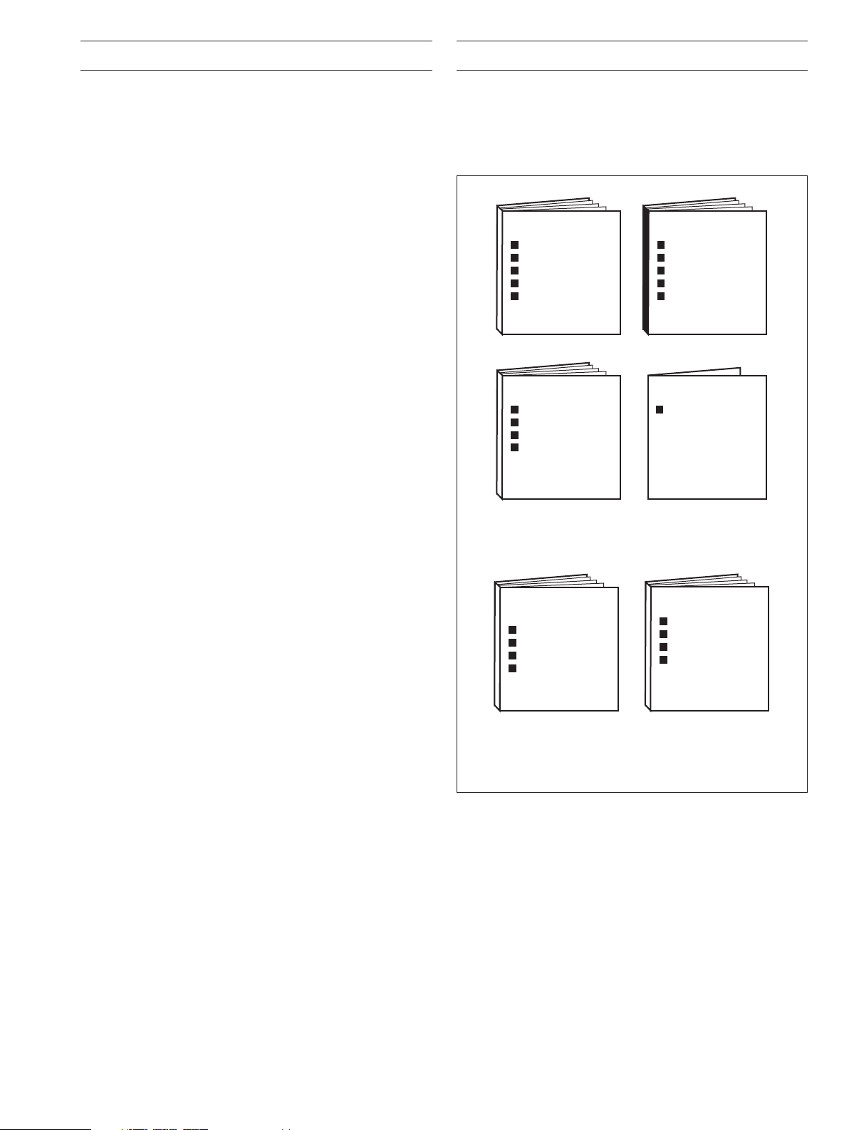
A – Standard Manuals
B – Supplementary Manuals
General Programming
Basic Config. Level
Advanced Config. Level
Connections and Links
CONTENTS 1 INTRODUCTION
Section Page
1 INTRODUCTION ........................................................... 1
2 SETTING UP ................................................................. 2
2.1 Instrument Power-up .......................................... 2
2.1.1 Power-up Error Codes .......................... 3
2.2 Fitting the Chart ..................................................4
2.3 Fitting the Pen Capsule(s) ................................... 4
3 DISPLAYS & CONTROLS............................................. 5
3.1 Displays and LED Indicators ............................... 5
3.2 Use of Controls ................................................... 6
4 OPERATION.................................................................. 7
4.1 Input Error Messages .......................................... 8
4.2 Operating Page Displays ..................................... 9
4.3 Alarm Acknowledge Page ................................. 10
4.3.1 Alarm Indications ................................. 10
4.3.2 Acknowledging Alarms ........................ 10
4.3.3 Using the Alarm
Acknowledge Page ............................. 10
4.4 Totals Page Displays ......................................... 11
4.5 Access to Configuration Levels .........................12
5 SIMPLE FAULT FINDING ........................................... 13
The documentation for the C1900 series of circular chart
recorders is shown in Fig. 1.1. The
Standard Manuals, including
the data sheet, are supplied with all instruments. The
Supplementary Manuals supplied depend on the specification of
the instrument.
6 SPARES LIST ............................................................. 14
Fig. 1.1 C1900 Documentation
1
Page 4
2 SETTING UP
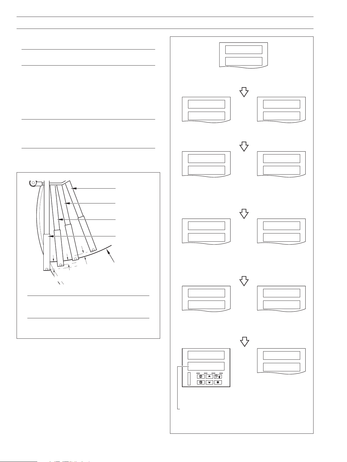
2.1 Instrument Power-up – Fig. 2.1 and 2.2
Caution. Ensure that all connections, especially to the
earth stud, are made correctly.
a) Check that the input sensors are installed correctly.
b) Check that the pen(s) are installed correctly – see Fig. 2.1.
c) Switch on the supply to the instrument, any power-operated
control circuits and the input signals. Wait for the pens to
settle.
Note. On power-up, the pens are moved to an off-
chart position for automatic referencing. Pen chatter
may occur on those pens nearest the reference
position. This is a normal function of the instrument.
d) The start-up sequence shown in Fig. 2.2 is displayed on
faceplate 1 when the supply is first switched on.
Blue Pen
(Channel 3)
Red Pen
(Channel 1)
Green Pen
(Channel 2)
Black Pen
(Channel 4)
Note
– see
Chart Time Line
0.35 (8.8)
0.175 (4.4)
0.175 (4.4)
Dimensions in inches (mm)
1914 J
tESt
Instrument Test identifies the instrument type, e.g.
1914J – see Table 2.1 in the
CPU
PASS
CPU Test carries out check of processor circuitry – see
Error Codes
below.
CONFIG
PASS
Configuration Test carries out check of non-volatile
memories containing the instrument configuration, then
indicates pass or fail – see
CAL
PASS
Calibration Test carries out check of non-volatile
memories containing the calibration data for each analog
input and output, then indicates pass or fail – see
below.
Codes
Installation Manual.
CPU
or
FAIL
CONFIG
or
FAIL
Error Codes
CAL
or
FAIL
below.
Error
Note. If the true time line event option is fitted, the
violet event pen records on the same time line as
the red pen, but on the outer edge of the chart.
Fig. 2.1 Checking the Pen(s) Installation
2
bb rAM
PASS
Battery Back RAM Test carries out check of batterybacked RAM, then indicates pass or fail – see
below.
Codes
or
!00.3
200.3
AL
AT
RMT
MAN
Normal Display
Not applicable on single
channel instruments
Fig. 2.2 Instrument Displays at Start-up
or
bb rAM
FAIL
Error
A––––F
–2–4––
Error Codes are
displayed in the event
of a fault – see Section
2.1.1.
Page 5
2 SETTING UP…
2.1.1 Power-up Error Codes
If any of the power-up tests fail (see Fig. 2.2), error codes are displayed to identify the fault. Refer to Fig. 2.3 for error code
interpretations.
A––––F
–2–4––
Code Error Action
– No error
1 Main board
2 Module in position 2
3 Module in position 3
4 Module in position 4
5 Module in position 5
6 Module in position 6
Code Error Action
– No error None
A
Configuration and battery-backed RAM errors
Calibration errors
Analog input and/or analog
output calibration is corrupt
Main program data stored in non-volatile
memory on main board is corrupt
None
Power down and then up again.
If fault remains, contact the local Service
Organisation.
Check and correct program data
C
d
F
Acknowledging Error Codes
Note. Acknowledging the Error Code clears the error state but does not rectify the fault.
After acknowledging the error, carry out the relevant action detailed in the above tables.
Timer set up stored in battery backed RAM is corrupt
Maths set up stored in battery back RAM is corrupt
Totalizer set up in battery backed RAM has been corrupt
ACKNLG
or
ErrOrS
Fig. 2.3 Power-up Error Codes
Check and correct data in
Check and correct data in
Check and correct data in
* Refer to the
Advanced Software Manual
100.3
200.5
Set Up Timer Page*
Set Up Maths Page*
Set Up Totals Page*
3
Page 6
…2 SETTING UP
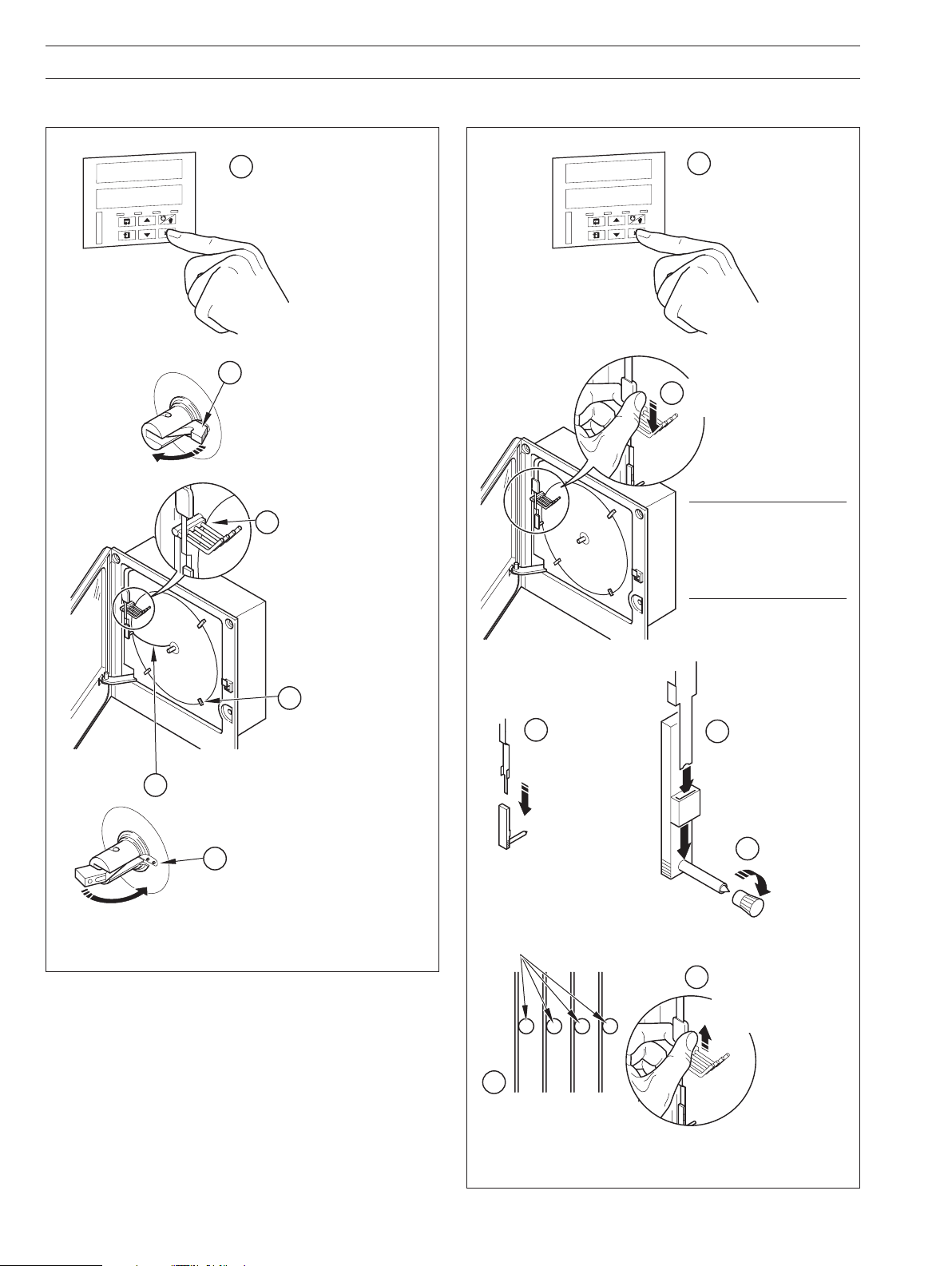
2.2 Fitting the Chart – Fig. 2.4 2.3 Fitting the Pen Capsule(s) – Fig. 2.5
Raise pens
75.0
dEG F
T
A
T
M
R
L
A
Raise pens
1
N
A
M
Lift the chart clamp
2
and remove the chart
75.0
dEG F
T
A
T
M
R
L
A
N
A
M
1
Gently pull the arm off
2
the bracket – see
Note
Fit new chart ensuring
3
that it is beneath the
pen lifter bars
4
Rotate chart to align the
5
time line with the red pen
(see also Fig. 2.1)
Lower the chart clamp
6
Fig. 2.4 Fitting the Chart
Locate chart
under guides
Lifter bars
3
Remove spent
capsule
Note. Take care not
to bend the arms
during removal and
refitting, as pen
clashing may result.
Fit new pen capsule
4
ensuring that the arm
locates in the pen
capsule slot
Remove cap
5
Slide pen assembly onto
7
the appropriate bracket
until it clips into place –
Note
see
6
Ensure that the arm is
positioned above its lifter
bar
Fig. 2.5 Fitting the Pen Capsules
4
Page 7

3 DISPLAYS & CONTROLS
The displays, LED indicators and operation/programming
controls are located on the faceplate on the front panel of the
instrument – see Fig 3.1.
3.1 Displays and LED Indicators – Fig. 3.1
The displays comprise 2 rows of 6 characters.
At the top of each programming page (the page header) both
displays are used to describe the particular page selected.
When parameters within the selected page are viewed the upper
display shows the parameter and the lower display shows the
value or setting for that parameter.
Alarm and Channel states are indicated by separate LEDs on the
faceplate of the front panel of the instrument – see Sections 4.1,
4.2 and 4.3.
Displays
LED Indicators –
see Section 4
Information.
AL1 – Channel 1
AL2 – Channel 2
AL3 – Channel 3
AL4 – Channel 4
CH1 – Channel 1
CH2 – Channel 2
CH3 – Channel 3
CH4 – Channel 4
8.8.8.8.8.8.
8.8.8.8.8.8.
Controls – Refer to Fig.
3.2(a) to (f) for functions
Status of process variable alarms
Current channel displayed
Fig. 3.1 Location of Displays,
Controls and LED Indicators
A
B
C
D
E
F
G
H
I
J
K
A
b
or
c
C
d
E
F
G
or
h
H
I
J
K
Table 3.1 Character Set
L
M
N
O
P
Q
R
S
T
U
V
Y
L
M
N
O
P
Q
r
S
t
U
V
Y
or
or
n
o
5
Page 8

…3 DISPLAYS & CONTROLS
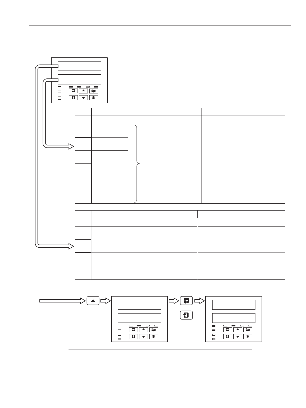
3.2 Use of Controls – Fig. 3.2(a) to (f)
Return from
any frame
Page 1
Frame 1
Frame 2
Frame 3
Frame 4
Page 2
Frame 1
Frame 2
Frame 3
Fig. 3.2(a) Advancing to Next Page
Page X
Frame 1
Advance to
next Frame
Frame 2
Frame 3
Frame 4
Fig. 3.2(b) Moving Between Parameters
Parameter Value
Adjust
Note. Continued pressure on the and keys
causes the rate of change of the displayed value to
increase. To make small adjustments operate the keys
momentarily.
Fig. 3.2(c) Adjusting a Parameter Value
Lift/Lower pen on alternate operations
Notes.
• The
Chart Page
key can be enabled or disabled in the Set Up
, BASIC CONFIGURATION LEVEL.
• If 'Auto Pen Lift Drop' has been selected in the Set Up
Chart Page
, the pens return automatically to their
operating positions after a five minute delay.
Fig. 3.2(e) Lifting/Lowering the Pens
Information. The key is programmed in the Set Up
Function Keys Page, ADVANCED CONFIGURATION
LEVEL.
Acknowledge all alarms
or
Operating Page
Page X
Parameter 1
Parameter 2
Op. Page
Parameter 1
Parameter 2
Return operator to top of
Page X
Parameter 1
Parameter 2
Note. The key returns the instrument display to the
start of the operating page only when the display is at
the top of any page.
.
Parameter X
Y
Select
Z
Note. Continued pressure on the and keys
causes the rate of change of the displayed value to
increase. To make small adjustments operate the keys
momentarily.
Fig. 3.2(d) Selecting a Parameter Choice
6
Fig. 3.2(f) Selecting Programmable Functions
Page 9

If Totalizer option
is not fitted or Totalizers
3 & 4 are off
PV1 & PV2
ACKNLG
ALArMS
Acknowledge Alarms
Alarm Identity/Type
SECOdE
____
Security Code
Alarm Acknowledge Page
Section 4.3 Page 10
Total Page
Section 4.4 Page 11
Security Code Page
Section 4.5 Page 12
Totalized Value
Reset Total
Stop/Go
____
____
PV1 & Units
PV2 & Units
tOtALS
PAGE
rESEt
t1___
COUNt
____
Total 1
Reset Total
Stop/Go
rESEt
t2___
COUNt
____
Total 2
____
____
____
____
____
____
____
____
____
____
Time
tIME
____
Date
dAtE
____
See
Note
If Totalizer option
is not fitted or
Totalizers 1 & 2 are off
Faceplate 1 Pages
PV3 & PV4
ACKNLG
ALArMS
Acknowledge Alarms
Alarm Identity/Type
Operating Page
Section 4.2 Page 9
Alarm Acknowledge Page
Section 4.3 Page 10
Total Page
Section 4.4 Page 11
Totalized Value
____
____
PV3 & Units
PV4 & Units
tOtALS
PAGE
Reset Total
Stop/Go
rESEt
t3___
COUNt
____
Total 3
Reset Total
Stop/Go
rESEt
t4___
COUNt
____
Total 4
____
____
____
____
____
____
____
____
____
____
Time
tIME
____
Date
dAtE
____
See
Note
Faceplate 2 Pages
OPrtOr
LEVEL
bASIC
CONFIG
AdVNCd
CONFIG
Basic Config
Advanced Config
Operator Level
Only applicable
with Timer option
Only applicable
with Timer option
Operating Page
Section 4.2 Page 9
______
ISS _
EPROM Identity
4 OPERATION
Fig. 4.1 Summary of Operating Level
pages are displayed only if an alarm is active.
Alarm Acknowledge
Note. The
7
Page 10

…4 OPERATION
The instrument has dedicated Operating Pages in the OPERATOR LEVEL – see Sections. 4.1 to 4.4. These pages are used for general
monitoring of the process measurements and are not affected by the security system which inhibits access to the PROGRAMMING
LEVELS
only – see Section 4.5 on page 12.
4.1 Input Error Messages – Fig. 4.2
Message Reason Action
Ad.FAIL
F–INPt
Examples
Internal analog to digital converter system hardware has failed • Check that the input/output board is located correctly
Input is above or below fault detection level.
or
Input exceeds the limits for the linearizer selected
in its socket.
• Power down and up
If the 'Ad.FAIL' message is still present, contact the
local service organization
• Check input source for possible broken sensor
• Check input connections
• Check input link position
• Check input configuration in
Set Up Input Page
Ad.FAIL
200.5
Note. Error messages are cleared automatically when the fault condition no longer exists.
Hardware failure on
Process Variable 1
Fig. 4.2 Input Error Messages Displayed in the Operating Page
200.5
F–INPt
Input out of range on
Process Variable 4
8
Page 11

4.2 Operating Page Displays
Faceplate 1 for channels 1 and 2 Faceplate 2 for channels 3 and 4
4 OPERATION…
100.3
200.5
CH1
AL1 AL2 AL3 AL4
CH2
CH3
CH4
100.3
dEG F
CH1
AL1 AL2 AL3 AL4
CH2
CH3
CH4
200.5
dEG F
CH1
AL1 AL2 AL3 AL4
CH2
CH3
CH4
Process Variable 1 (PV1)
Process Variable 2 (PV2)*
*Not displayed on single pen
recorder.
Process Variable 1 (PV1)
Temperature Units for PV1
as set in the
CONFIGURATION LEVEL.
BASIC
Display is blank if 'NONE' is
selected.
Process Variable 2 (PV2)
Temperature Units for PV2
as set in the
CONFIGURATION LEVEL.
Display is blank if '
BASIC
NONE' is
selected.
300.3
400.5
CH1
AL1 AL2 AL3 AL4
CH2
CH3
CH4
300,3
dEG F
CH1
AL1 AL2 AL3 AL4
CH2
CH3
CH4
400.5
dEG F
CH1
AL1 AL2 AL3 AL4
CH2
CH3
CH4
Process Variable 3 (PV3)
Process Variable 4 (PV4)*
* Not displayed on three pen
recorders.
Process Variable 3 (PV3)
Temperature Units for PV3
as set in the
CONFIGURATION LEVEL.
BASIC
Display is blank if 'NONE' is
selected.
Process Variable 4 (PV4)
Temperature Units for PV4
as set in the
CONFIGURATION LEVEL.
Display is blank if '
BASIC
NONE' is
selected.
tIME
12. 00
CH1
AL1 AL2 AL3 AL4
CH2
CH3
CH4
dAtE
24 JAN
CH1
AL1 AL2 AL3 AL4
CH2
CH3
CH4
Current Time*
Time* (displayed using 24hr
clock)
*Displayed only when timer
option is fitted.
Current Date*
Day and Month*
*Displayed only when timer
option is fitted.
tIME
12. 00
CH1
AL1 AL2 AL3 AL4
CH2
CH3
CH4
dAtE
24 JAN
CH1
AL1 AL2 AL3 AL4
CH2
CH3
CH4
Current Time*
Time* (displayed using 24hr
clock)
*Displayed only when timer
option is fitted.
Current Date*
Day and Month*
*Displayed only when timer
option is fitted.
9
Page 12

…4 OPERATION
4.3 Alarm Acknowledge Page
4.3.1 Alarm Indications – Fig. 4.3
The definitions for alarm states (on, off or flashing) are detailed in
Fig. 4.3.
4.3.2 Acknowledging Alarms
Note. Channel 1 and 2 alarms can be acknowledged
only from faceplate 1. Channel 3 and 4 alarms (if
applicable) can be acknowledged only from faceplate 2.
Unacknowledged alarms can be acknowledged from the
faceplate controls on the front panel in two ways:
OPERATING LEVEL – by pressing the key at any
In the
frame (providing the key is programmed for this function –
see Section 4.1 in the Programming Manual).
Alarm Acknowledge Page – by pressing the key –
In the
see Section 4.3.3 following.
No LED illuminated indicates no
CH1
AL1 AL2 AL3 AL4
CH2
CH3
CH4
CH1
AL1 AL2 AL3 AL4
CH2
CH3
CH4
CH1
AL1 AL2 AL3 AL4
CH2
CH3
CH4
Fig. 4.3 Alarm LED Indications
alarms active.
The
Alarm Acknowledge Page
displayed in the
OPERATOR LEVEL
is not
A flashing LED indicates an
unacknowledged alarm on that
channel. For example, a flashing
AL1
LED indicates an
unacknowledged alarm on
channel 1.
The
Alarm Acknowledge Page
now displayed in the
LEVEL
.
is
OPERATOR
A constant LED indicates that all
active alarms have been
acknowledged on that channel.
The
Alarm Acknowledge Page
remains in the
OPERATOR LEVEL
until all alarm conditions are
cleared on that channel.
.
4.3.3 Using the Alarm Acknowledge Page
No Alarm Active
302
795
CH1
AL1 AL2 AL3 AL4
CH2
CH3
CH4
Alarm Activated
302
802
CH1
AL1 AL2 AL3 AL4
CH2
CH3
CH4
ACKNLG
ALArM5
CH1
AL1 AL2 AL3 AL4
CH2
CH3
CH4
A2HPrC
800
CH1
AL1 AL2 AL3 AL4
CH2
CH3
CH4
A2HPrC
ACKNGd
CH1
AL1 AL2 AL3 AL4
CH2
CH3
CH4
No LED indicators illuminated.
Alarm Active
AL2 LED indicator flashing,
indicating active alarm on
channel 2.
Use
Alarm Acknowledge Page.
key to go to top of
Alarm Acknowledge Page
Use
key to advance to next
frame
Alarm Identity
Upper display: shows the alarm
identity and type.
Lower Display: shows the trip
level of the alarm identified in
the upper display.
Acknowledge Alarm
Use key to acknowledge
the alarm (see). When the alarm
is acknowledged, '
displayed and a constant LED
indicates the acknowledged
alarm.
ACKNGd' is
10
If there are more active alarms on channel 2 the LED continues to
flash until all alarms for that channel have been acknowledged.
Note. The key or a digital input can also be used to
acknowledge alarm, if programmed.
Page 13

4 OPERATION…
4.4 Totals Page Displays
This page is omitted from both faceplates if the Totalizer Option is not fitted. The page is also omitted from faceplate 1 if both Totals
1 and 2 are set to
Software Options Manual.
OFF and from faceplate 2 if both Totals 3 and 4 are set to OFF – refer to the Set Up Totals Page in the Advanced
tOtALS
PAGE
CH1
AL1 AL2 AL3 AL4
CH2
CH3
CH4
1234
5678
CH1
AL1 AL2 AL3 AL4
CH2
CH3
CH4
rESEt
tI NO
CH1
AL1 AL2 AL3 AL4
CH2
CH3
CH4
If
YES
selected
t1 YES
t1 YES
t1 NO
tOtALS
PAGE
CH1
AL1 AL2 AL3 AL4
CH2
CH3
CH4
8765
4321
CH1
AL1 AL2 AL3 AL4
CH2
CH3
CH4
rESEt
tI NO
CH1
AL1 AL2 AL3 AL4
CH2
CH3
CH4
Front Panel (Batch) Flow Total 1 (3)
The batch flow total is calculated from process variable
1 (3). The flow total can be reset if
Totals Page is set to 'ENbL–Y'.
Reset Enable in Set Up
The flashing channel LED indicates the flow total
displayed.
For example, a flashing channel 1 LED indicates
Total 1 parameters displayed.
Flow
Counter Reset
The Front (Batch) Flow Total can be reset to the
Value in Set Up Totals Page if required.
Preset
Select 't1 YES' to reset the counter ( 't1' indicates
Flow Total 1 ).
Note. If the Counter Reset is disabled in Set Up Totals
Page, the counter reset frame is omitted.
COUNt
StOP
CH1
AL1 AL2 AL3 AL4
CH2
CH3
CH4
Repeat for Total 2 (if applicable)
1234
5678
CH1
AL1 AL2 AL3 AL4
CH2
CH3
CH4
GO
GO
StOP
COUNt
StOP
CH1
AL1 AL2 AL3 AL4
CH2
CH3
CH4
Repeat for Total 4 (if applicable)
8765
4321
CH1
AL1 AL2 AL3 AL4
CH2
CH3
CH4
Counter Stop/Go
GO' to start the counter or 'StOP' to stop it.
Select '
Note. If the Counter Stop/Go is disabled in
Set Up
Totals Page, the frame can be viewed but not altered. If
a digital signal is assigned to the Totalizer Stop/Go, an
active digital signal sets the counter to
GO and the
Counter cannot be stopped from the front panel.
Front Panel (Batch) Flow Total 2 (4)
Repeat the above procedure for
Flow Total 2 (4).
Note. The number of totalizers is dependent on the
number of pens fitted to the instrument e.g. a 3 pen
instrument has 3 totalizers.
11
Page 14

…4 OPERATION
4.5 Access to Configuration Levels
A security system is used to prevent tampering with the programmed parameters by utilizing a password giving access to all
programming pages – refer to the
SECOdE 100.0
CH1
AL1 AL2 AL3 AL4 CH1
CH2
CH3
CH4
Correct
Password
PEN 1
CH1
AL1 AL2 AL3 AL4
CH2
CH3
CH4
PEN 4
CH1
AL1 AL2 AL3 AL4
CH2
CH3
CH4
2001
Programming Manual.
Security Code
the pen adjustment
password
75.5 100
Incorrect
Password
Pen Position Adjustment (Pens 1 to 4)
The position of any trend pen can be adjusted against a reference standard (without
changing the displayed value). Each pen can be adjusted in steps upwards (towards
the edge of the chart) or downwards (towards the center of the chart).
When this feature is enabled, a password must be entered before adjustments can
be made.
Note if pen adjustment is disabled or if the password is incorrect, the four Pen
Adjustment frames are not displayed.
For each trend pen, the lower part of the frame shows the pen position adjustment.
Pen position adjusted downwards by > 25 steps
Pen position adjusted downwards by between 1 and 25 steps
Pen position not adjusted
Pen position adjusted upwards by between 1 and 25 steps
Pen position adjusted upwards by > 25 steps
adjusts the pen position upwards (towards outer edge of chart)
adjusts the pen position downwards (towards center of chart)
The pen adjustment frame for any given pen only appears if the pen is a Trend pen
EPROM
Version
AL1 AL2 AL3 AL4
CH2
CH3
CH4
Security Code Page
Set the security code to the correct
password using the
keyes and use the key
to advance to other programming
levels (OPERATOR, BASIC
CONFIGURATION and ADVANCED
CONFIGURATION).
The password is programmed in
the Access Page in the
BASIC CONFIGURATION LEVEL.
and
OPrtOr
LEVEL
CH1
AL1 AL2 AL3 AL4
CH2
CH3
CH4
BASIC
CONFIG
CH1
AL1 AL2 AL3 AL4
CH2
CH3
CH4
ISS _
CH1
AL1 AL2 AL3 AL4
CH2
CH3
CH4
EPROM Identification
Use the
Identification Frame. The upper display
shows the EPROM version, e.g. 2001
and the lower display shows the EPROM
issue number.
OPt ION
tYPE 0
CH1
AL1 AL2 AL3 AL4
CH2
CH3
CH4
12
EPROM
Issue
Number
key to advance to the EPROM
Option
Shows the software key option type.
For details of the options, refer to the
Data Sheet, SS/C1900R
AdUNCd
CONFIG
CH1
AL1 AL2 AL3 AL4
CH2
CH3
CH4
Page 15

5 SIMPLE FAULT FINDING
Symptom Possible Cause Action
Does not power up a) Internal fuse (if fitted) is blown a) Check wiring, rectify fault and replace fuse
b) Internal power switch (if fitted) is OFF b) Turn power switch ON
c) Power supply connections are incorrect c) Check connections
Chart does not appear to move a) Very slow chart speed selected a) Select required chart speed in
Chart Page
Set Up
b) Chart stop function enabled b) De-activate source being used to stop
chart – see
Set Up Chart Page
Pens in recording position but do not drop Chart stop function enabled De-activate source used to stop chart – see
onto paper
Set Up Chart Page
Red pen does not move beyond 94% When real time event pen is fitted the red pen Use chart range which prevents the need to go
position on chart cannot go beyond 94% to prevent pens beyond 94% of maximum on chart
clashing
Pen lift switch on front panel does not Pen lift switch is disabled Enable pen-lift switch in
Set Up Chart Page
work
Pens do not remain lifted when pen lift key Auto pen drop feature is enabled Disable auto pen drop in
Set Up Chart Page
if
is used this is not required
Analog inputs are slow to respond A large filter time has is set Set digital filter value to give required response
in
Set Up Inputs
Time or date incorrect Not set for correct local time Set correct time and date in
Page
– refer to
Advanced Software Manual
Totalizers cannot be set to STOP or GO Operator STOP/GO selection is not enabled Enable counter STOP/GO in the
in the
OPERATOR LEVEL Totals Page
Set Up Clock
Set Up
Totalizer cannot be set to STOP Digital signal assigned to the total STOP/GO De-activate digital signal assigned to total
function is active STOP/GO function
External relays connected to relays in Arc suppression capacitors are provided Remove the arc suppression components –
instrument fail to de-energize across the relay contacts and capacitor IC4 and IC5 on mainboard
leakage current may be sufficient to prevent IC6 and IC7 on standard I/O and analog relay
an external relay from de-energizing IC3 to IC10 on 4 relay module
13
Page 16

6 SPARES LIST
Item Part No.
Pen Capsules (pack of 3)
Black ............................................................................................................................................................................. C1900/0119
Blue ............................................................................................................................................................................... C1900/0120
Red ................................................................................................................................................................................ C1900/0121
Green ............................................................................................................................................................................. C1900/0122
Violet* ............................................................................................................................................................................ C1900/0123
Pen Arm Assemblies
ER/C Type Chart (J or R in Code Number) – Standard Pen ........................................................................................... C1900/0076
ER/C Type Chart (J or R in Code Number) – Event Pen ................................................................................................ C1900/0078
PX105 and PXR105 Type Chart (K or S in Code Number) – Standard Pen ................................................................... C1900/0075
PX105 and PXR105 Type Chart (K or S in Code Number) – Event Pen ......................................................................... C1900/0077
Fuses
24V ................................................................................................................................................................................ B11071 (4A)
115V .............................................................................................................................................................................. B11070 (1A)
230V ....................................................................................................................................................................... B11069 (500mA)
*True time line event option only.
14
Page 17

NOTES
15
Page 18

NOTES
16
Page 19

Sales SoftwareService
Page 20

—
ABB Limited
Measurement & Analytics
Howard Road, St. Neots
Cambridgeshire, PE19 8EU
UK
Tel: +44 (0)870 600 6122
Fax: +44 (0)1480 217 948
Email: enquiries.mp.uk@gb.abb.com
ABB Inc.
Measurement & Analytics
125 E County Line Road
Warminster, PA 18974
USA
Tel: +1 215 674 6000
Fax: +1 215 674 7183
abb.com/measurement
—
We reser ve the right to m ake techni cal changes or modify the co ntents of th is docume nt
with out prior notice . With reg ard to purch ase orders, the agreed par ticula rs shall prevail.
ABB do es not accept any respon sibilit y whatsoever for potent ial error s or possible lack of
information in this document.
We reser ve all right s in this document and in the su bject matter and illustration s containe d
therein. Any rep roduction, disclos ure to third pa rties or utilization of its contents – in
whole o r in parts – is for bidden w ithout prior writ ten consent of AB B.
© ABB 20 18
IM/C19 00-OG R Rev. L 09.2018
 Loading...