

Page 1
—
ABB MEASUREMENT & ANALYTICS | USER GUIDE
C1300
Advanced circular chart recorder
Measurement made easy
—
C130 0 advanced c ircular
chart recorder
For more information
Further publications are available for free download
from:
www.abb.com/measurement
or by scanning this code:
Advanced circular chart recorder
Datasheet
Advanced circular chart recorder
User Guide supplement
Advanced sofware options
Advanced circular chart recorder
User Guide supplement
Modbus communications option
Search for or click on
Page 2
Electrical Safety
Health and Safety
This equipment complies with the requirements of CEI/IEC
for Measurement, Control and Laboratory Use’. If the
the protection provided by the equipment may be impaired.
Symbols
equipment labelling:
Warning – refer to the manual for instructions
Caution – risk of electr ic shock
Protective earth (ground) terminal
Earth (ground) terminal
Direc t current supply only
Alternating current supply only
To ensure that our products are safe and without risk to health,
the following points must be noted:
• The relevant sections of these instructions must be read
carefully before proceeding.
• Warning labels on containers and packages must be
observed.
• Installation, operation, maintenance and servicing must
only be carried out by suitably trained personnel and in
accordance with the information given.
• Normal safety precautions must be taken to avoid the
possibility of an accident occurring when operating in
conditions of high pressure and/or temperature.
• Chemicals must be stored away from heat, protected from
temperature extremes and powders kept dry. Normal safe
handling procedures must be used.
• When disposing of chemicals ensure that no two chemicals
are mixed.
Safety advice concerning the use of the equipment described in
this manual or any relevant hazard data sheets (where
applicable) may be obtained from the Company address on the
back cover, together with servicing and spares information.
Both direct and alternating current supply
The equipment is protected through double insulation
Information in this manual is intended only to assist our
customers in the efficient operation of our equipment. Use of
this manual for any other purpose is specifically prohibited and
its contents are not to be reproduced in full or part without
prior approval of the Technical Publications Department.
Page 3

C1300
Advanced circular chart recorder Contents
Contents
1 Preparation ......................................................................2
1.1 Preparing the Recorder for First Use ........................2
1.2 Powering up the Recorder .......................................4
1.2.1 Recorder Status and Error Page ...................5
2 Operation .........................................................................6
2.1 Display Screens and Operator Keys .........................6
2.2 Input Error Messages and Alarm Icons .....................7
2.3 Operating Pages ......................................................8
2.3.1 Accessing the Operating Pages ....................8
2.3.2 Autoscroll .....................................................9
2.3.3 Input (Pen) Channel Display – Separate ......10
2.3.4 Input (Pen) Channel Display – Dual ..............11
2.3.5 Input (Pen) Channel Display – Separate
and Dual .....................................................12
2.3.6 Totalizer Display – Separate ........................13
2.3.7 Totalizer Display – Rate with Total ............... 13
2.3.8 Totalizer Display – Total with Rate ...............14
2.3.9 Totalizer Display – Dual Total ......................14
2.3.10 Totalizer Display – Dual + Flow Rate ...........15
2.3.11 Data Logging .............................................15
2.4 Totalizer Log ..........................................................16
2.5 Totalizer Control .....................................................17
2.6 Alarm Set Point Adjustment ...................................18
3 Configuration .................................................................19
3.1 Introduction ............................................................19
3.2 Preparation for Configuration .................................19
3.3 Configuration Level Security ...................................19
3.4 Common Configuration ..........................................20
3.5 Channels Configuration ..........................................24
3.6 Alarms Configuration ..............................................31
3.7 Totalizer Configuration ...........................................35
3.8 Relay Configuration ................................................42
3.9 Digital Input and Output Configuration ....................43
3.10 Analog Output Configuration ..................................45
3.11 Logic Equation Configuration .................................47
3.12 Data Logging Configuration ....................................50
3.13 System Clock Configuration ...................................54
3.14 Pen Function ..........................................................55
3.15 Calibration ..............................................................56
3.16 Backing Up and Restoring Configurations ..............58
3.16.1 Backing Up a Configuration ........................58
3.16.2 Restoring a Configuration ...........................59
5 Electrical Installation .................................................... 64
5.1 Identifying the Input/Output Modules ..................... 66
5.2 Channel Connections ............................................ 66
5.2.1 Selecting the Analog Input Type(s) .............. 67
5.2.2 Voltage and Current ................................... 69
5.2.3 2-wire Transmitter Input) ............................ 69
5.2.4 Thermocouple ............................................ 69
5.2.5 Resistance Thermometer (RTD) .................. 69
5.2.6 Logic Inputs ............................................... 69
5.2.7 Analog Output ............................................ 69
5.2.8 Relay Output .............................................. 69
5.3 Module Connections .............................................. 70
5.3.1 Standard I/O or Analog + Relay
(Module Types 1, 2 and 7) .......................... 70
5.3.2 Four Relay Module (Module Type 3) ........... 70
5.3.3 Eight Digital Inputs or Outputs
(Module Types 4 and 5 respectively) ........... 70
5.4 Power Supply Selection
and AC Connections ............................................. 71
6 Fault Diagnosis ............................................................. 72
7 Spares and Accessories .............................................. 73
8 Specification ................................................................. 74
Appendix A – Signal Sources ........................................... 77
Appendix B – Units ........................................................... 78
Appendix C – Installation Record .................................... 80
Index .................................................................................. 82
Acknowledgments ........................................................... 84
4 Mechanical Installation .................................................60
4.1 Siting .....................................................................60
4.2 Mounting ................................................................61
4.2.1 Wall-/Pipe-Mounting ...................................62
4.2.2 Panel Mounting ...........................................63
IM/C1300 Rev. J 1
Page 4
C1300
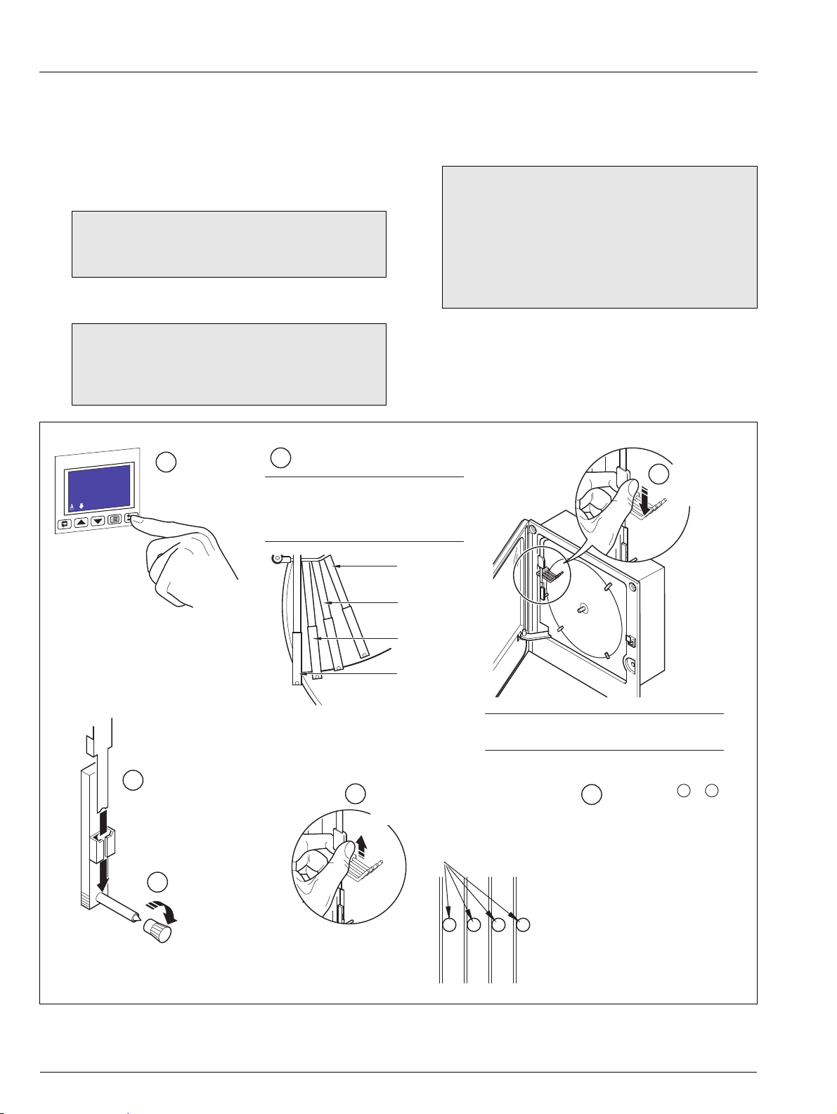
Gently pull
the pen arm
off its bracket
3
Note. Do not bend the pen arm during removal
and re-fitting as pen clashing may result.
Raise pens
1
Input 1
-999.99
deg C
5
Remove cap
Fit the correct colored pen
capsule ensuring that the arm
locates in the pen
capsule slot
4
Red Pen
(Channel 1)
Green Pen
(Channel 2)
Blue Pen
(Channel 3)
Black Pen
(Channel 4)
2
Identify pens
Note. The number of pens fitted (and
the colors of the pen capsules
supplied) depends on the recorder
model.
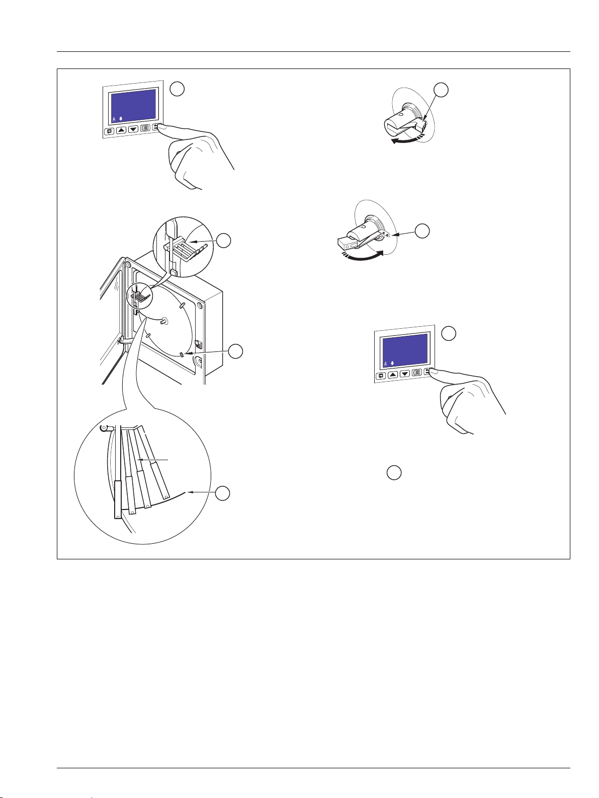
Slide pen arm and capsule
assembly onto the appropriate
bracket until it clips into place
6
ensuring that the arm is
positioned above its lifter bar
7
Repeat steps to for
remaining pens as required
3 6
Advanced circular chart recorder 1 Preparation
1 Preparation
1.1 Preparing the Recorder for First Use
Prepare the recorder for first use as follows:
1. Install the recorder – see Section 4, page 60.
2. Connect the recorder – see Section 5, page 64.
Warning. Ensure all connections are made correctly,
especially to the earth (ground) stud – see Section
5.4, page 71.
3. Switch on the power supply to the recorder.
4. Fit the pen capsule(s) – see Fig. 1.1.
Note.
Ensure the correct colored capsule is fitted to
the appropriate pen arm. Each pen arm is
identified by a colored band – see Fig. 1.1.
If the violet, true-time line event option is fitted,
the pen records on the same time line as the red
pen, but on the outer edge of the chart.
Note. On power-up, the pen arm(s) is (are) moved to
an off-chart position for automatic referencing. Pen
chatter may occur on the pen(s) nearest the reference
position. This is a normal function of the recorder.
5. Fit a chart – see Fig. 1.2 on page 3.
Fig. 1.1 Fitting the Pen Capsule(s)
2 IM/C1300 Rev. J
Page 5
C1300
Lift the chart clamp
2
Lower the chart clamp and press down
firmly to ensure that the 2 locating pins
pierce the paper
6
Ensure pen(s) in
raised position
1
Input 1
-999.99
deg C
Fit a chart ensuring
that it is beneath the
pen lifter bars
Locate chart
under guides
Rotate chart to align the
time line with the red pen
3
4
Red Pen
5
Lower pen(s)
7
Input 1
-999.99
deg C
Switch off the power supply to the recorder
8
Advanced circular chart recorder 1 Preparation
Fig. 1.2 Fitting a Chart
IM/C1300 Rev. J 3
Page 6
C1300
WWW.abb.com
Self Tests, Software Key and
Module Identification
Instrument Type and Software Version
C1314J
Software Issue
1
Main: CFG Test :Pass
SKey:Type B :Pass
Mod2:Not Fitted
Mod3:Not Fitted
Mod4:Not Fitted
Mod5:Not Fitted
Mod6:Not Fitted
Advanced circular chart recorder 1 Preparation
1.2 Powering up the Recorder
To power up the recorder:
1. Switch on the supply to the recorder, any power-operated control circuits and the input signals. Wait for the pens to settle.
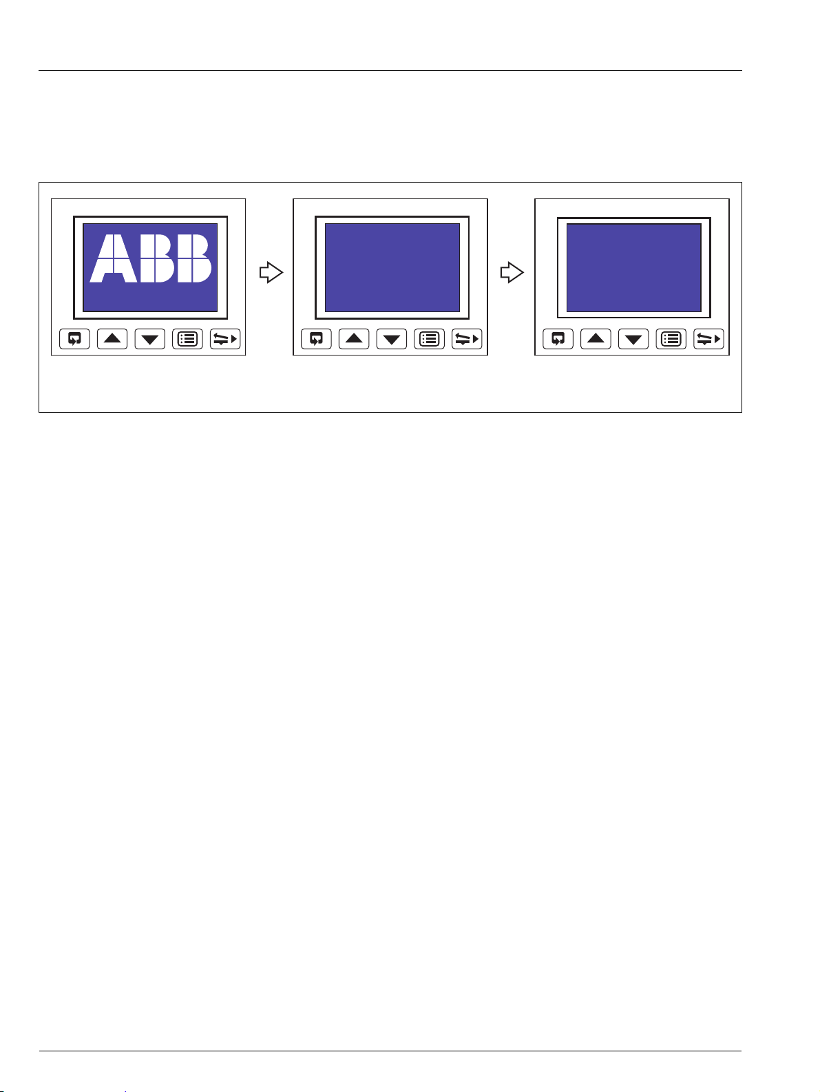
2. The start-up self-test sequence shown in Fig. 1.3 is shown on display screen 1 when the power supply is first switched on.
Fig. 1.3 Recorder Start-up Self-test Sequence
4 IM/C1300 Rev. J
Page 7
C1300
Main: CFG Test :Pass
SKey:Type B :Pass
Mod2:Not Fitted
Mod3:Not Fitted
Mod4:Not Fitted
Mod5:Dig Out :Pass
Mod6:RS485 :Pass
Main Board CPU and Configuration Test Results
Software Key (see
Note below) Identification and Test Result
Module Identification and Test Results
Acknowledging Errors
Mod2:Not Fitted
Mod3:Not Fitted
Mod4:Not Fitted
Mod5:Dig Out :Fail
Mod6:RS485 :Pass
Acknowledge
Input 1
-999.99
deg C
Component Possible Cause Action
Module in position 2
Module in position 3
Module in position 4
Module in position 5
Module in position 6
Main Board
Software Key
Analog input and/or analog output calibration is corrupt.
Power down and then up again.
If the fault persists, contact the Company.
Configuration stored in non-volatilememory is corrupt.
Check and correct program data.
If the fault persists, contact the Company.
Note. The software key is optional hardware that is fitted to enable optional software features – Totalizers, Math
Blocks, System Clock and Timers.
Note. Acknowledging an Error Message clears the error state but does not rectify the fault. After acknowledging an
error, carry out the appropriate action detailed in the above table.
Advanced circular chart recorder 1 Preparation
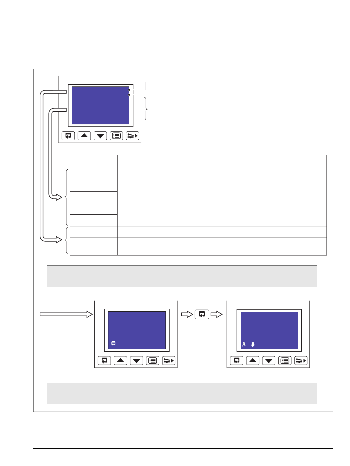
1.2.1 Recorder Status and Error Page
If any of the start-up self-tests (see Fig. 1.3) fail, the error message 'Fail' is displayed. Refer to Fig. 1.4 for possible cause and remedial
action information.
Fig. 1.4 Start-up Error Messages
IM/C1300 Rev. J 5
Page 8
C1300
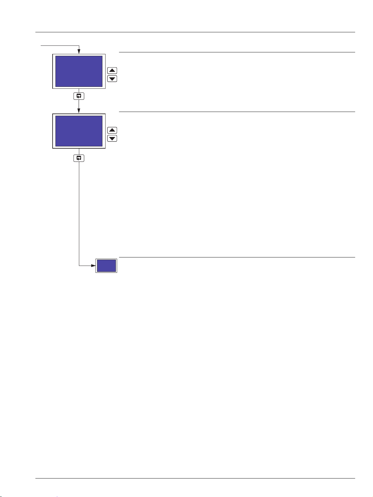
Making a Selection
Enter/Edit User-defined Information
Adjusting and Storing a Parameter Value
Select
Save selection and
advance to next screen
Raise/Lower Pens
If Auto Pen Drop is set to Yes (Section 3.4), the
key
raises/lowers the pen(s) on alternate operations when
Operating Level is selected from the Main Menu.
Press to advance to the next screen
Main Menu Screen
Press
to open the main menu screen
Select Channel
Pen
4
3
2
1
Pen 1 Tag
Boiler 1
Edit>
_ Pen 1 Tag
_!#$%&()*+,./01234
56789:;<=>?@ABCDEFGHI
JKLMNOPQRSTUVWXYZ[\]^
_abcdefghijklmnopqrs
tuvwxyz{|}WºdbSp ?
Exit Cursor
Use the and keys to select the character to be displayed
at the cursor position see
Note below.
Use the
key to move the cursor.
Press to save the new value and advance to the next screen.
Pen 1 Eng. Hi
100.00 deg C
The first number flashes. Use the and keys to
change the value as required see
Note below.
Each press of the
key selects the next number to
the right. Use the
and keys to change the value
as required see
Note below.
Press to save the new value and advance to the
next screen.
Display
Screen
Operator Keys
Operating Level
Alarm Setpoints
Security Code
Common
Channels
Alarms
Relays
Digital I/O
Highlight a
menu item
Operating Level
Alarm Setpoints
Security Code
Common
Channels
Alarms
Relays
Digital I/O
Display Screen and Operator Keys
Cursor
Note. Continued pressure on the and keys causes the rate of change of the displayed value to increase.
Press the keys momentarily to make small adjustments.
Advanced circular chart recorder 2 Operation
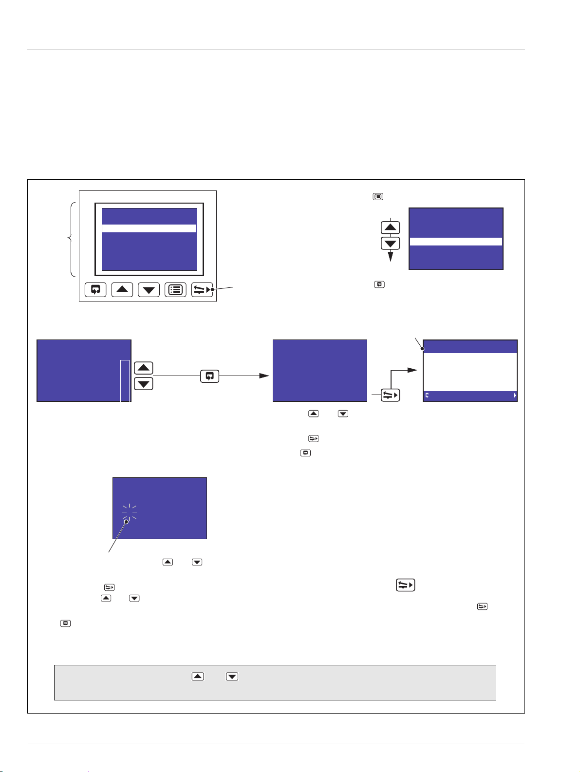
2Operation
2.1 Display Screens and Operator Keys
Up to two faceplates are fitted to the front of the recorder, each comprising a display screen and associated operator keys – see
Fig. 2.1.
Each high resolution, dot matrix display screen shows the operating and programming information for up to two input channels in a
variety of formats.
Alarm states are indicated by icons in the lower left corner of the display screen(s) – see Fig. 2.3 on page 7.
Fig. 2.1 Display Screen and Operator Keys
6 IM/C1300 Rev. J
Page 9
C1300
Hardware failure on
Process Variable 1
Examples
Input out of range on
Process Variable 1
Boiler 1
Error3
gal/d
Boiler 1
F-inpt
gal/d
Message Reason Action
Error1
Error2
Error3
Finpt
Unspecified error from the Analog to Digital Converter
Corrupt data from the Analog to Digital Converter
No reply from the Analog to Digital Converter
Input is above or below fault detection level
or
Input exceeds the limits for the linearizer selected
Check that the input/output board is located correctly in its socket
see Section 5.1
Power down and up
If the error message is still present, contact the Company
Check input source for possible broken sensor
Check input connections
Check input link position
Check input configuration see Section 3.5
Note. Error messages are cleared automatically when the fault condition no longer exists.
Global Alarm Indicator displayed if any alarm in any channel is active
High Process
Low Process
relevant only to the channel currently displayed
Fast Rate
Slow Rate
Advanced circular chart recorder 2 Operation
The recorder has dedicated Operating Pages in the Operating Level – see Sections 2.3 to 2.6. These pages display the process
measurements and are not affected by the security system which inhibits access to the Configuration Pages – see Section 3.3,
page 19.
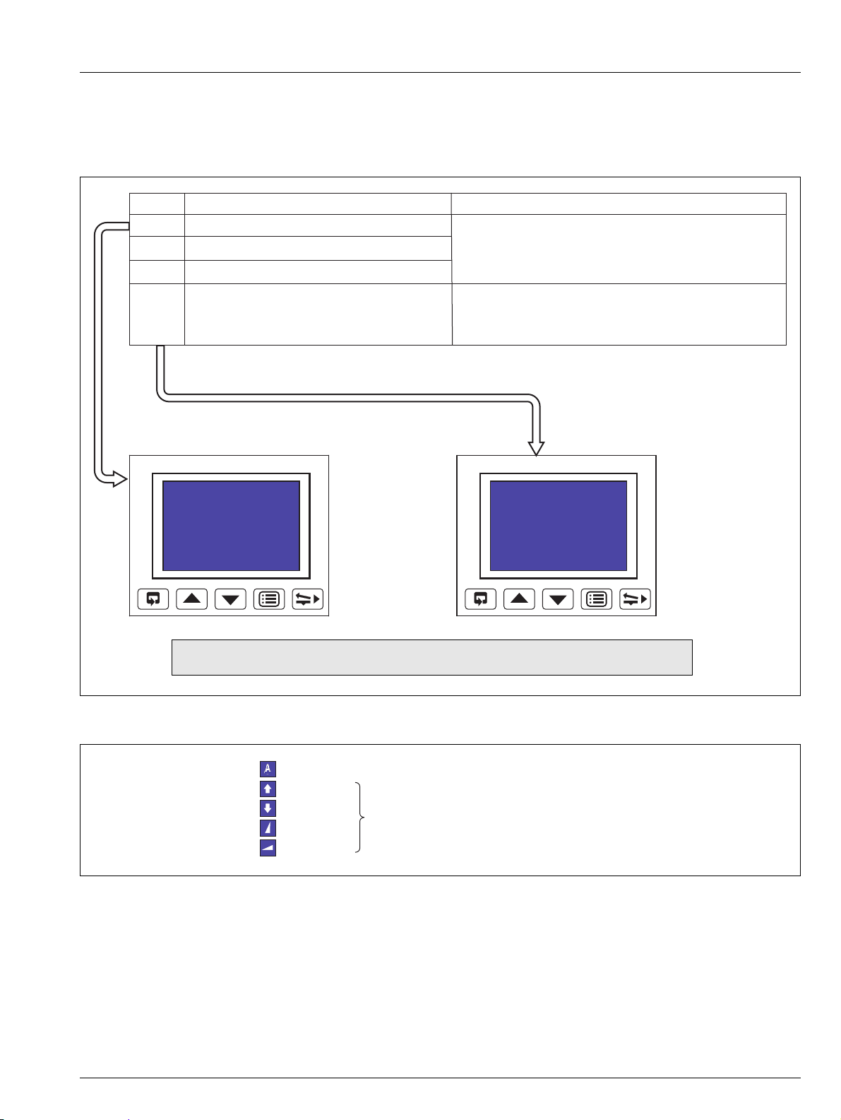
2.2 Input Error Messages and Alarm Icons
Fig. 2.2 Input Error Messages Displayed in the Operating Page
Fig. 2.3 Alarm Icons
IM/C1300 Rev. J 7
Page 10
C1300
Operating Level
Totalizer Log
Totalizer Control
Alarm Setpoints
Security Code
Common
Channels
Alarms
Input 1
-999.99
deg C
Advanced circular chart recorder 2 Operation
2.3 Operating Pages
Overview.
The following information is displayed in the Operating Pages:
– Input (pen) channel readings
– Data logging status (if data logging option is enabled by installation of the appropriate hardware)
– System time/date (if any one of the Totalizer, Math or Timers software options are enabled by installation of the
appropriate software key)
– Totalizer readings (if the totalizer software option is enabled by installation of the appropriate software key)
– Totalizer log (if the totalizer software option is enabled by installation of the appropriate software key)
– Totalizer control (if the totalizer software option is enabled and Totalizer Reset is set to YES – see Section 3.4, page 20.)
– Alarm set points (if Alarm Adjust is set to Yes – see Section 3.4, page 20.)
The Input (pen) channel and totalizer displays are configured separately (see Pen Ch Display and Totals Display in Section
3.4) and each can be displayed in one of several ways. Input channel information can be displayed without totalizer information
and vice-versa.
Input channel 1 and 2 information and system time/date is shown on display screen 1.
If the recorder is fitted with the optional second faceplate:
– Input channel 3 and 4 information, together with system time/date is shown on display screen 2
– Totalizer logs, totalizer control and alarm set point adjustment for pens 3 and 4 and associated totalizers are accessed
from the menu shown on display screen 2 when the key is pressed on faceplate 2.
Totalizer information is shown on the same display screen as the pen to which the totalizer is assigned.
All channel and totalizer configuration is done using faceplate 1.
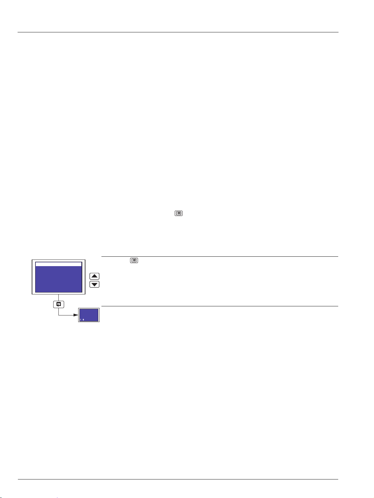
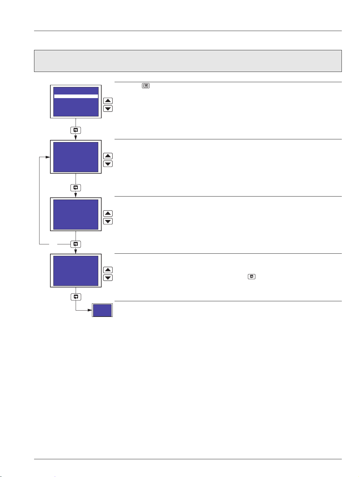
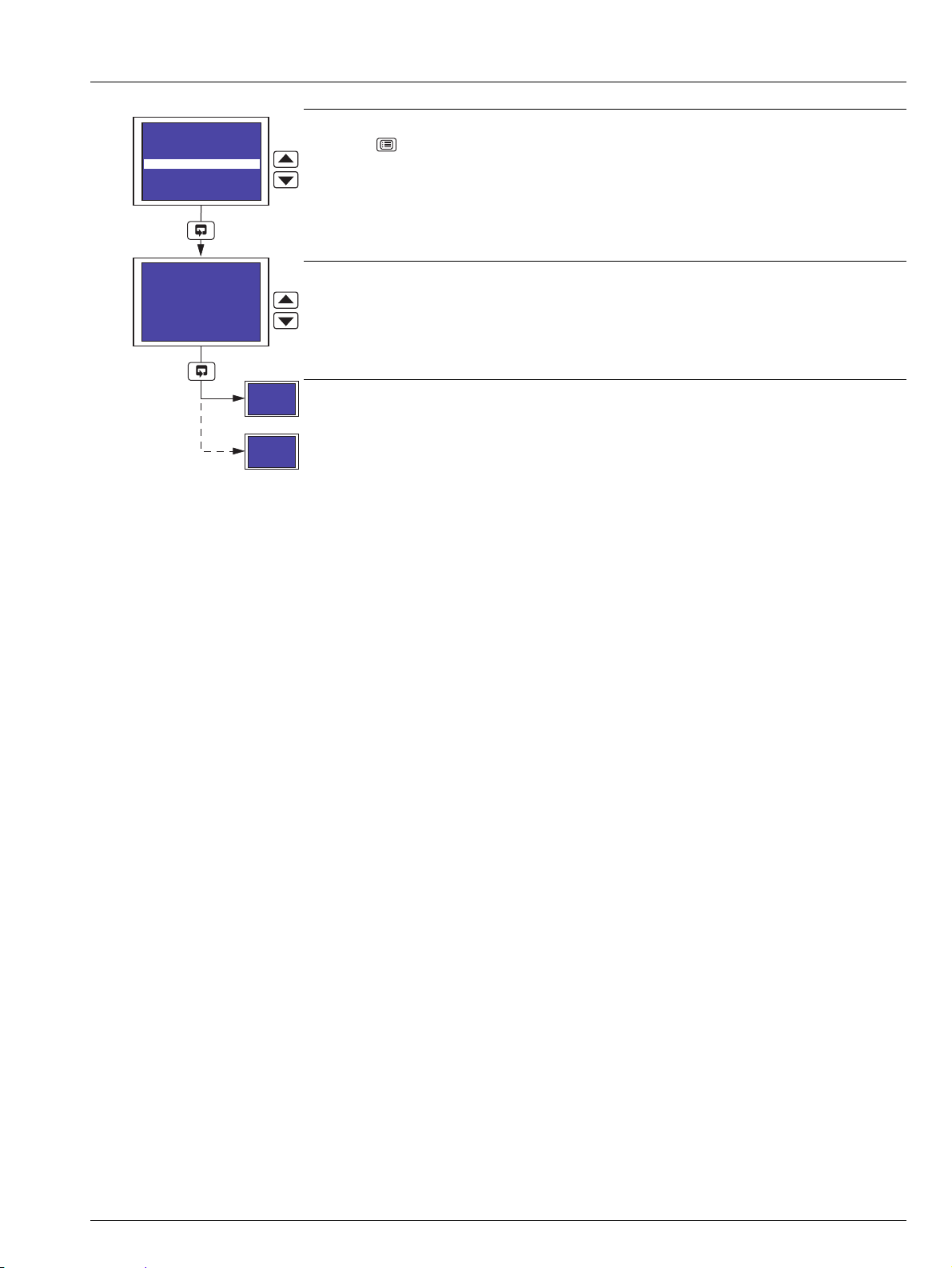
2.3.1 Accessing the Operating Pages
Press the key to open the Main Menu.
Highlight Operating Level.
see Section 2.3.3, page 10.
8 IM/C1300 Rev. J
Page 11
C1300
Input 1
-999.99
deg C
Autoscroll On
Slow Rate
Autoscroll On
Fast Rate
Autoscroll Off
Autoscroll On
Slow Rate
Advanced circular chart recorder 2 Operation
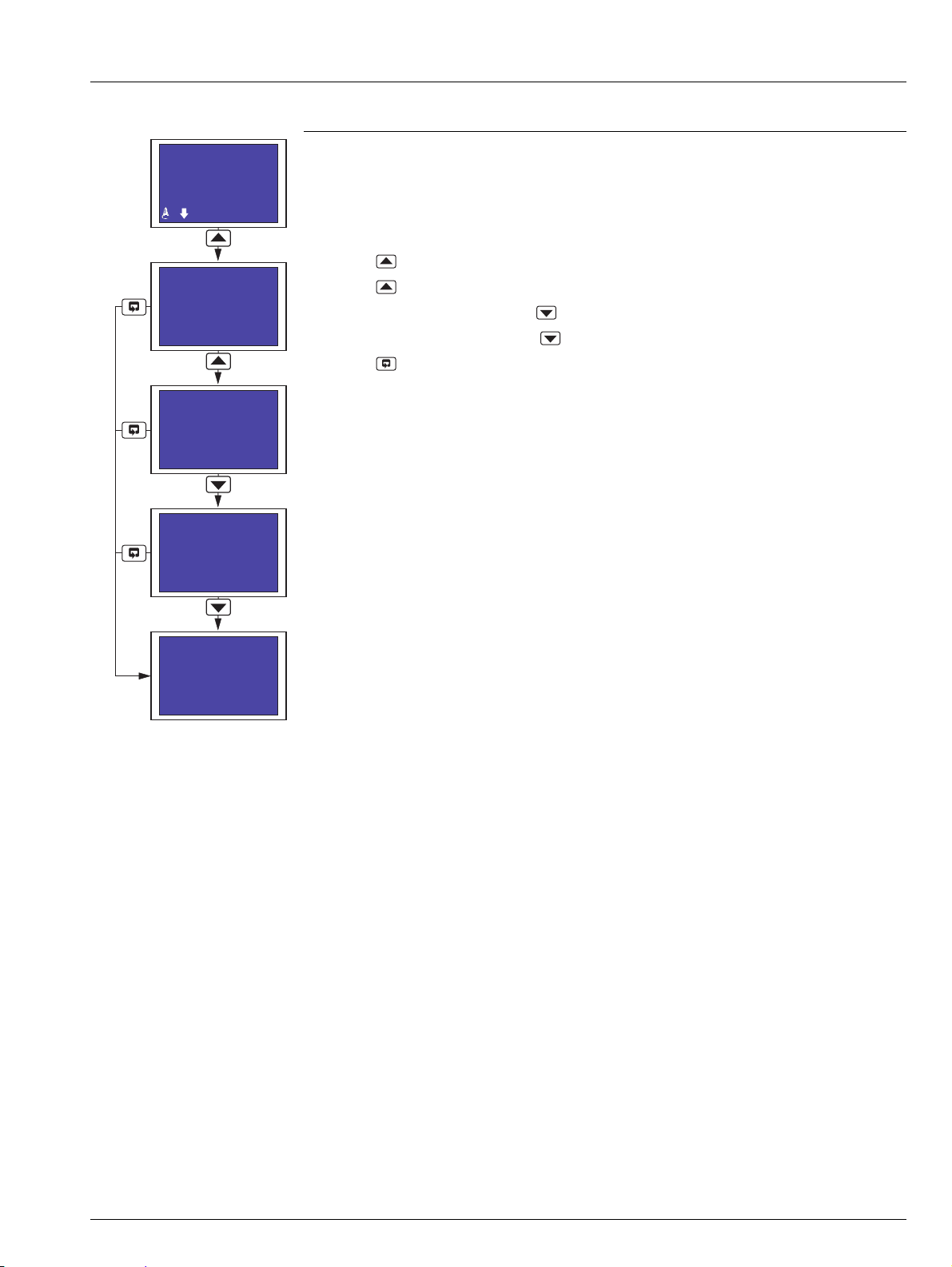
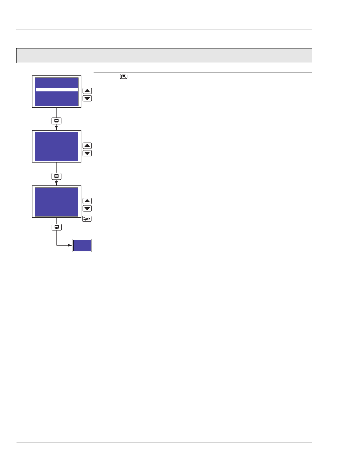
2.3.2 Autoscroll
Autoscroll
When Autoscroll is set to On, each Operating Page screen is displayed in turn for a period of
time determined by the rate selected:
Slow Rate – each screen is displayed in turn for 10 seconds
Fast Rate – each screen is displayed in turn for 5 seconds
Press the key from any Operating Page screen to initiate Autoscroll in Slow Rate mode.
Press the key again to switch to Fast Rate mode.
When in Fast Rate mode, press the key to switch to Slow Rate mode.
When in Slow Rate mode, press the key to switch Autoscroll off.
Press the key at any time to switch Autoscroll off.
IM/C1300 Rev. J 9
Page 12
C1300
Input 1
-999.99
deg C
System Time
Tuesday
25th May 2004
14:33:48
Input 2
O.OOO
m3/s
Totalizer 1
000000000
Input 1
-999.99
deg C
Input 1
-999.99
deg C
System Time
Tuesday
25th May 2004
14:33:48
Data Logging
Status: Online
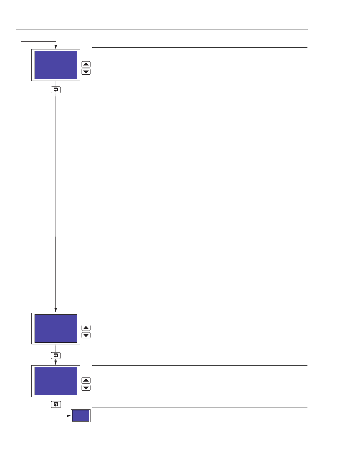
Advanced circular chart recorder 2 Operation
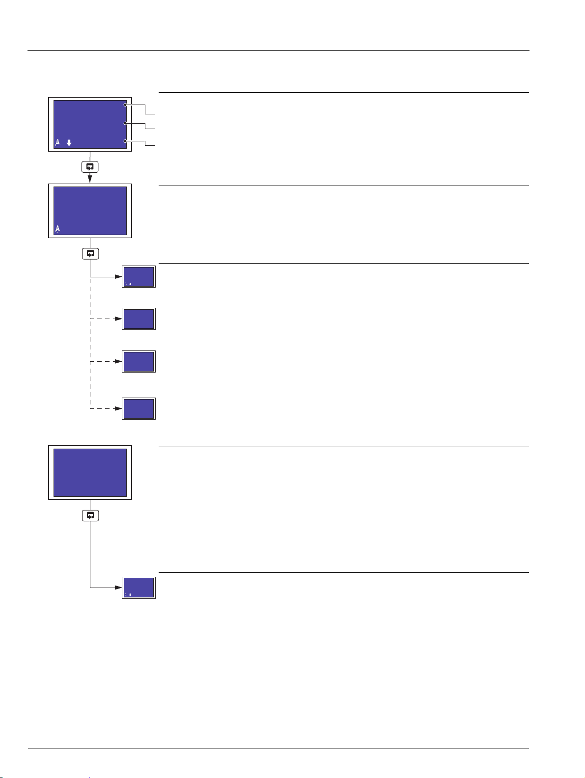
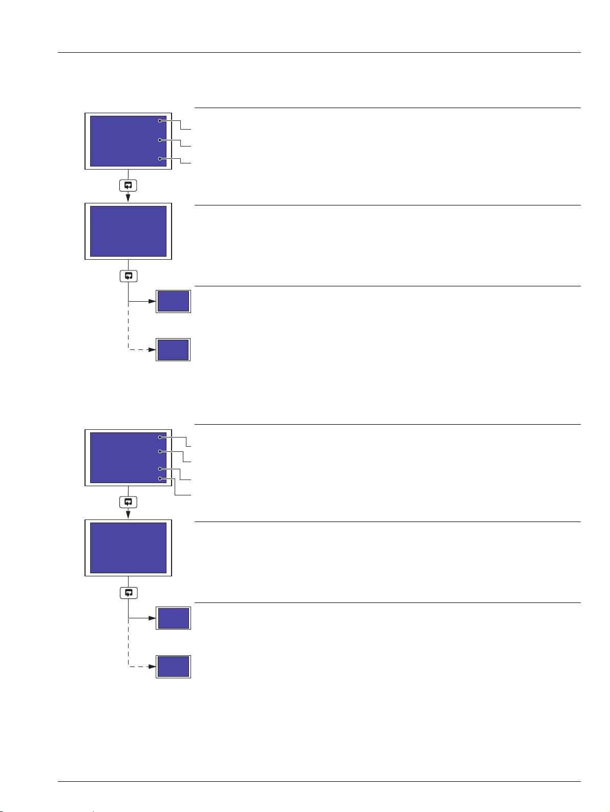
2.3.3 Input (Pen) Channel Display – Separate
The following screens are displayed only if Pen Ch Display is set to Separate – see Section 3.4, page 20.
Input Channel 1 (Pen 1)
Channel tag.
Measured value.
Alarm icons and measured value units.
Note. If Pen 1 Source is set to None (Section 3.14), only a measured value of 0 is displayed.
Input Channel 2 (Pen 2)
Note. If Pen 2 Source is set to None (Section 3.14), only a measured value of 0 is displayed.
Totalizer, Math or Timers software options not enabled by installation of the appropriate software
key and optional Data Logging hardware not installed – return to top of page.
Totalizer software option enabled by installation of the appropriate software key and To ta l s
Display not set to Off (Section 3.4) – see Sections 2.3.6 to 2.3.10.
Optional Data Logging hardware installed – see Section 2.3.11, page 15.
Optional Data Logging hardware not installed and Totalizer software option enabled by
installation of the appropriate software key and Totals Display set to Off (Section 3.4) –
continued below.
System Time/Date Display
Notes.
Available only if any one of the Totalizer, Math or Timers software options are enabled by
installation of the appropriate software key, or the optional Data Logging hardware is
installed.
If Pen Ch Display and Totals Display are set to Off (Section 3.4) and any of the above
software options are enabled and the optional Data Logging hardware is not installed, the
System Time Display is the only Operating Page screen available.
Return to top of page.
10 IM/C1300 Rev. J
Page 13

C1300
Input 1
O.O l/s
Input 2
O.OOO m3/s
Totalizer 1
000000000
Input 1
O.O l/s
Input 2
O.OOO m3/s
System Time
Tuesday
25th May 2004
14:33:48
Data Logging
Status: Online
Advanced circular chart recorder 2 Operation
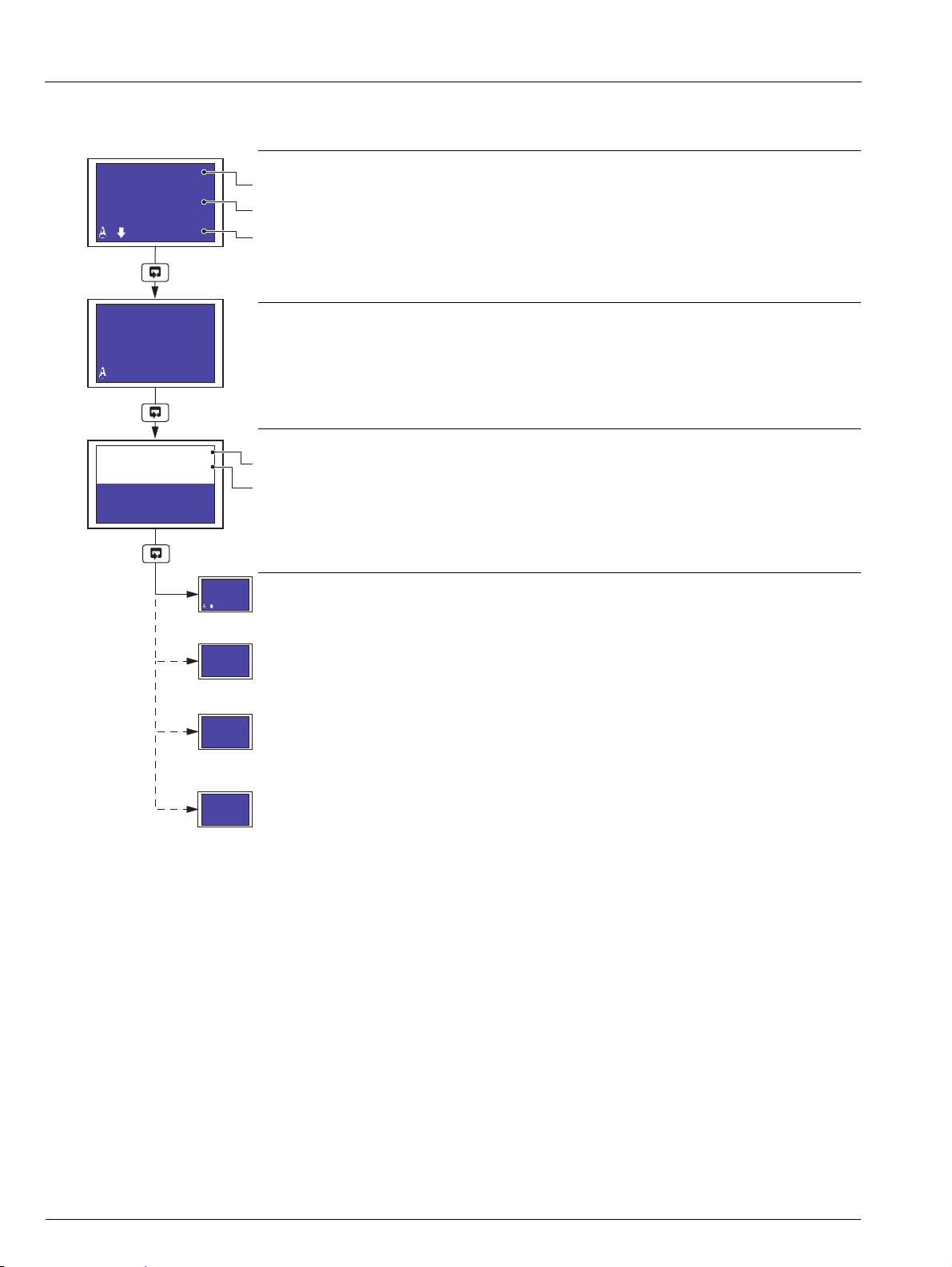
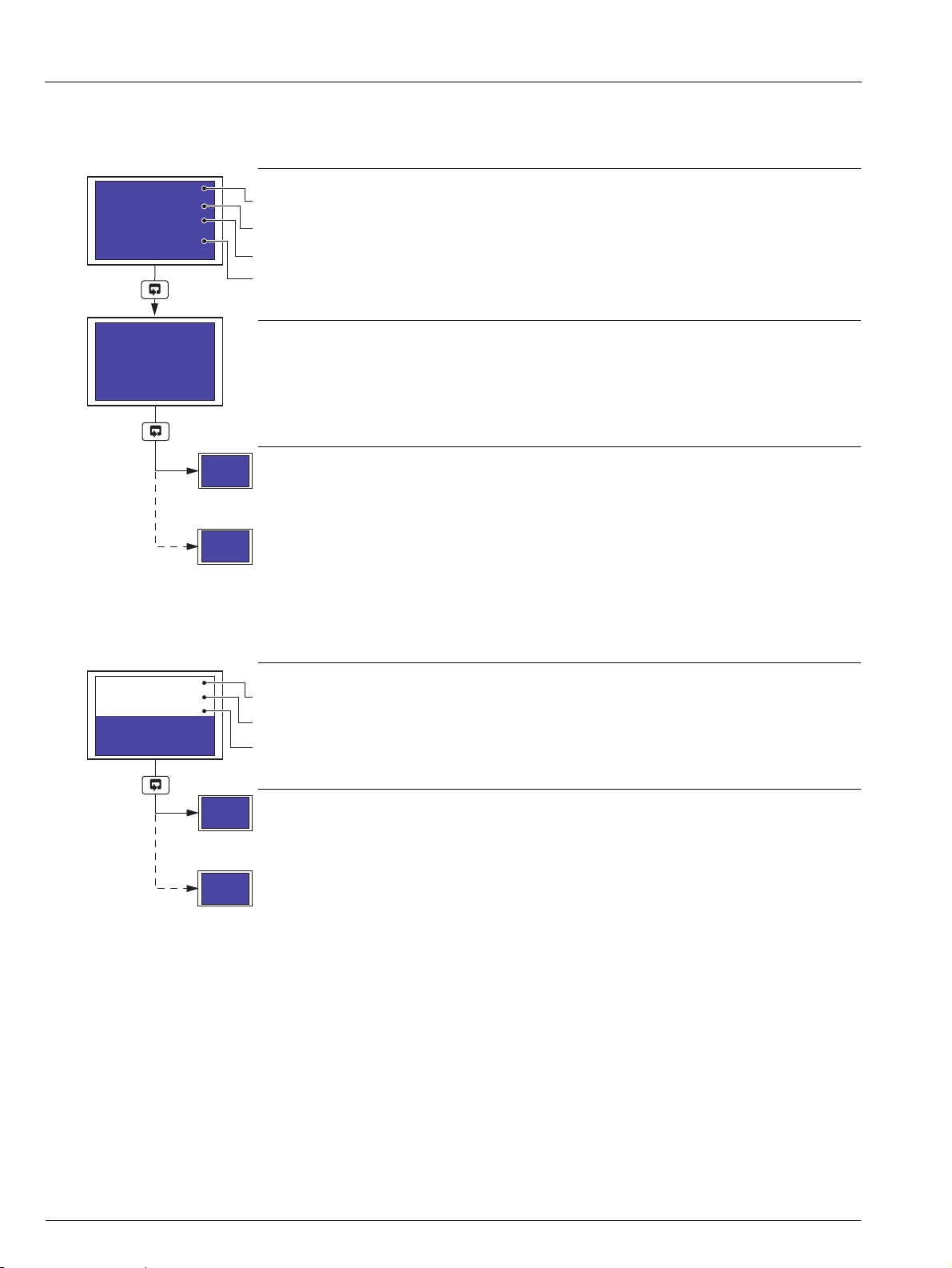
2.3.4 Input (Pen) Channel Display – Dual
The following screens are displayed only if Pen Ch Display is set to Dual – see Section 3.4, page 20.
Input Channels 1 and 2 (Pens 1 and 2)
Channel tag.
Measured value and units.
Note. If Pen X Source (where X is the pen number) is set to None (Section 3.14), only a
measured value of 0 is displayed for that channel.
Totalizer, Math or Timers software options not enabled by installation of the appropriate software
key and optional Data Logging hardware not installed – return to top of page.
Totalizer software option enabled by installation of the appropriate software key and Totals
Display not set to Off (Section 3.4) – see Sections 2.3.6 to 2.3.10.
Optional Data Logging hardware installed – see Section 2.3.11, page 15.
Optional Data Logging hardware not installed and Totalizer software option enabled by
installation of the appropriate software key and Totals Display set to Off (Section 3.4) – see
Section 2.3.3, page 10.
IM/C1300 Rev. J 11
Page 14
C1300
Input 2
O.OOO
m3/s
Input 1
-999.99
deg C
Input 1
O.O l/s
Input 2
O.OOO m3/s
Totalizer 1
000000000
Input 1
-999.99
deg C
System Time
Tuesday
25th May 2004
14:33:48
Data Logging
Status: Online
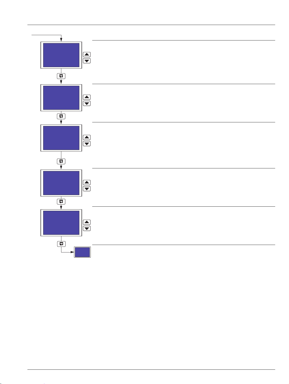
Advanced circular chart recorder 2 Operation
2.3.5 Input (Pen) Channel Display – Separate and Dual
The following screens are displayed only if Pen Ch Display is set to Separate & Dual – see Section 3.4, page 20.
Input Channel 1 (Pen 1)
Channel tag.
Measured value.
Alarm icons and measured value units.
Note. If Pen 1 Source is set to None (Section 3.14), only a measured value of 0 is displayed.
Input Channel 2 (Pen 2)
Note. If Pen 2 Source is set to None (Section 3.14), only a measured value of 0 is displayed.
Input Channels 1 and 2 (Pens 1 and 2)
Channel tag.
Measured value and units.
Note. If Pen X Source (where X is the pen number) is set to None (Section 3.14), only a
measured value of 0 is displayed for that channel.
Totalizer, Math or Timers software options not enabled by installation of the appropriate software
key and optional Data Logging hardware not installed – return to top of page.
Totalizer software option enabled by installation of the appropriate software key and To ta l s
Display not set to Off (Section 3.4) – see Sections 2.3.6 to 2.3.10.
Optional Data Logging hardware installed – see Section 2.3.11, page 15.
Optional Data Logging hardware not installed and Totalizer software option enabled by
installation of the appropriate software key and Tot a l s D i s p la y set to Off (Section 3.4) – see
Section 2.3.3, page 10.
12 IM/C1300 Rev. J
Page 15
C1300
Totalizer 1
000000000
Ml
Totalizer 2
000000000
gal
System Time
Tuesday
25th May 2004
14:33:48
Data Logging
Status: Online
Input 1
87.6 gal
000005320
gal
Input 2
856.35 Ml
000027839
Ml
System Time
Tuesday
25th May 2004
14:33:48
Data Logging
Status: Online
Advanced circular chart recorder 2 Operation
2.3.6 Totalizer Display – Separate
The following screens are displayed only if Totals Display is set to Separate (Section 3.4) and Tot X Source (where X is the totalizer
number) is set to anything other than None – see Section 3.7, page 35.
Totalizer 1
Totalizer tag.
Totalizer value.
Totalizer value units.
Totalizer 2
Optional data logging hardware installed – see Section 2.3.11, page 15.
2.3.7 Totalizer Display – Rate with Total
The following screens are displayed only if Totals Display is set to Rate with Total (Section 3.4) and To t X S o u r c e (where X is the
totalizer number) is set to anything other than None – see Section 3.7, page 35.
Optional data logging hardware not installed – see Section 2.3.3, page 10.
Totalizer 1
Channel tag.
Measured value and measured value units.
Totalizer value.
Totalizer value units.
Totalizer 2
Optional data logging hardware installed – see Section 2.3.11, page 15.
IM/C1300 Rev. J 13
Optional data logging hardware not installed – see Section 2.3.3, page 10.
Page 16
C1300
Totalizer 1
000005320
gal
87.6 gal
Totalizer 2
000027839
Ml
856.35 Ml
System Time
Tuesday
25th May 2004
14:33:48
Data Logging
Status: Online
Totalizer 1
000005320
gal
Totalizer 2
000027839
Ml
System Time
Tuesday
25th May 2004
14:33:48
Data Logging
Status: Online
Advanced circular chart recorder 2 Operation
2.3.8 Totalizer Display – Total with Rate
The following screens are displayed only if Totals Display is set to Total with Rate (Section 3.4) and Tot X Source (where X is the
totalizer number) is set to anything other than None – see Section 3.7, page 35.
Totalizer 1
Totalizer tag.
Totalizer value.
Totalizer units.
Measured value and measured value units.
Totalizer 2
Optional data logging hardware installed – see Section 2.3.11, page 15.
Optional data logging hardware not installed – see Section 2.3.3, page 10.
2.3.9 Totalizer Display – Dual Total
The following screen is displayed only if Totals Display is set to Dual Total (Section 3.4) and Tot X Source (where X is the totalizer
number) is set to anything other than None – see Section 3.7, page 35.
Totalizers 1 and 2
Totalizer tag.
Totalizer value.
Totalizer units.
Optional data logging hardware installed – see Section 2.3.11, page 15.
Optional data logging hardware not installed – see Section 2.3.3, page 10.
14 IM/C1300 Rev. J
Page 17
C1300
87.6
gal/h
000279513
|1
472.6
gal/h
008831908
|2
System Time
Tuesday
25th May 2004
14:33:48
Data Logging
Status: Online
System Time
Tuesday
25th May 2004
14:33:48
Data Logging
Status: Online
Memory Used: 25%
Remove Card
Data Logging
Status: Offline
It is now safe to
remove the
Compact Flash
(59s)
Data Logging
Status: Not Present
Advanced circular chart recorder 2 Operation
2.3.10 Totalizer Display – Dual + Flow Rate
The following screen is displayed only if Totals Display is set to Dual + Flow Rate (Section 3.4) and Tot X Source (where X is the
totalizer number) is set to anything other than None – see Section 3.7, page 35.
Totalizers 1 and 2
Measured value and measured value units.
Totalizer value.
Totalizer units and channel number.
Optional data logging hardware installed – see Section 2.3.11, below.
Optional data logging hardware not installed – see Section 2.3.3, page 10.
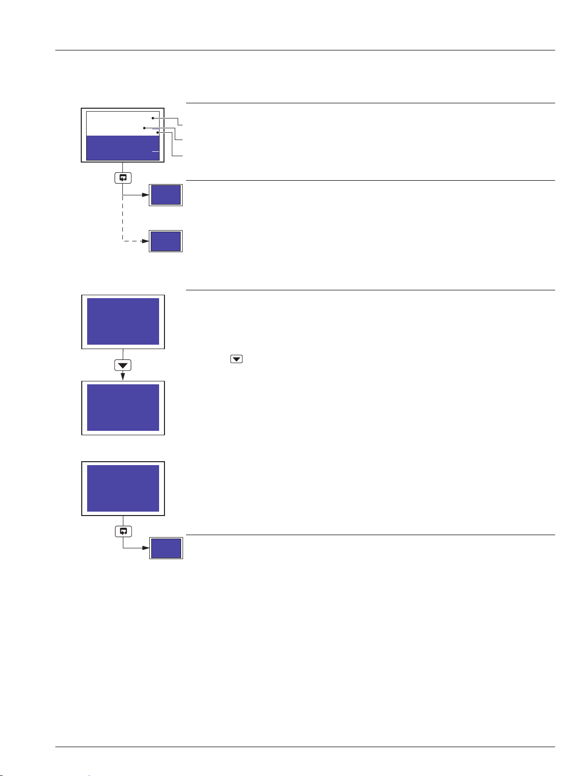
2.3.11 Data Logging
Data Logging Status
Provides information on current data logging status.
Press the key to place data logging off-line.
When data logging is off-line, the Compact Flash card can be removed safely.
If the card is not removed within 1 minute, data logging is placed on-line automatically. A timer
indicates the number of seconds remaining before data logging resumes.
This screen is displayed when a Compact Flash card is not inserted.
Data logging starts automatically when a Compact Flash card is inserted.
see Section 2.3.3, page 10.
IM/C1300 Rev. J 15
Page 18
C1300
Select Totalizer
Totalizer 1
Select Totalizer
Totalizer 1
19th Apr 04 15:30
Totalizer 1
000047824
gal
Max : 78
Min : 22
Avg : 56
Operating Level
Totalizer Log
Totalizer Control
Alarm Setpoints
Security Code
Common
Channels
Alarms
Advanced circular chart recorder 2 Operation
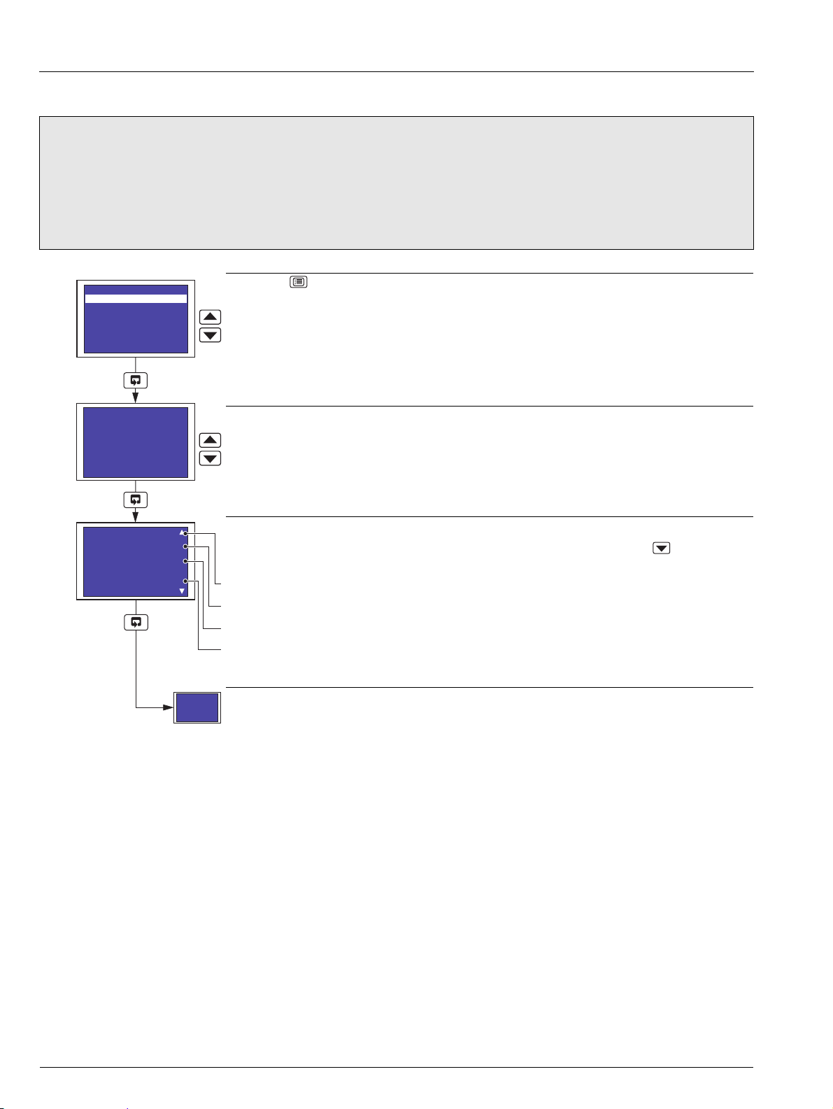
2.4 Totalizer Log
Note.
The totalizer log is available only if the totalizer software option is enabled by installation of the appropriate software key.
The recorder can store up to 21 log entries for each enabled totalizer. When the maximum number of entries has been
reached, the oldest data is overwritten by the newest.
A new log entry is created for each totalizer at the interval selected in the Tot X Log Enable parameter (where X is the
totalizer number) – see Section 3.7, page 35.
Press the key to open the Main Menu.
Highlight Totalizer Log.
Select Totalizer
Select the totalizer log to display.
Totalizer Log
The first log displayed for the selected totalizer is the most recent. Use the key to display
each log in descending date order.
Date and time.
Totalizer tag.
Current value and units.
Maximum, minimum and average values.
Note. If no log entries exist, Log is empty is shown on the display screen.
Return to top of page.
16 IM/C1300 Rev. J
Page 19
C1300
Select Totalizer
Totalizer 1
Totalizer 1
Reset - NO
000000913
Operating Level
Totalizer Log
Totalizer Control
Alarm Setpoints
Security Code
Common
Channels
Alarms
Totalizer 1
Confirm - NO
000000913
NO
Totalizer 1
Reset - NO
000000913
Advanced circular chart recorder 2 Operation
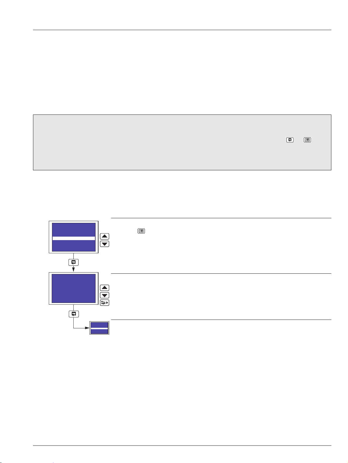
2.5 Totalizer Control
Note. Totalizer control is available only if the totalizer software option is enabled by installation of the appropriate software key
and Totalizer Reset is set to YES – see Section 3.4, page 20.
Press the key to open the Main Menu.
Highlight Totalizer Control.
Select Totalizer
Select the totalizer to reset.
Reset Totalizer
Select YES to reset the totalizer.
Confirm Reset Totalizer
Select YES to reset the totalizer.
Note. If YES is selected, the totalizer is reset when the key is pressed.
Return to previous frame.
IM/C1300 Rev. J 17
Page 20
C1300
Select Alarm
A1
A1 Trip
10.000 deg C
Operating Level
Totalizer Log
Totalizer Control
Alarm Setpoints
Security Code
Common
Channels
Alarms
Select Alarm
A1
Advanced circular chart recorder 2 Operation
2.6 Alarm Set Point Adjustment
Note. Alarm set point adjustment is available only if Alarm Adjust is set to YES – see Section 3.4, page 20.
Press the key to open the Main Menu.
Highlight Alarm Adjust.
Select Alarm
Select the alarm to adjust.
Alarm Set Point
Adjust the alarm set point.
Return to top of page.
18 IM/C1300 Rev. J
Page 21
C1300
Enter Code
0000
Operating Level
Totalizer Log
Totalizer Control
Alarm Setpoints
Security Code
Common
Channels
Alarms
Operating Level
Totalizer Log
Totalizer Control
Alarm Setpoints
Security Code
Common
Channels
Alarms
Advanced circular chart recorder 3 Configuration
3 Configuration
3.1 Introduction
The configuration procedures are used to make changes to the operating parameter values and for scale adjustment. Configuration
of all channels is performed from faceplate 1.
The configuration settings can be backed up to a PC and restored to the recorder as required – see Section 3.16, page 58.
An overview of the Configuration Pages is on the rear cover fold-out.
When changing the input type, it may be necessary to reposition the input selector links accordingly – see Section 5.2.1, page 67.
3.2 Preparation for Configuration
Note.
Isolate any external alarm/control circuits if inadvertent operation during configuration is undesirable.
The recorder responds instantly to parameter changes. These are saved automatically when either the or key is
pressed.
The display screen of faceplate 2 (if fitted) shows Configuration Mode when the configuration pages are accessed by
scrolling past Security Code in the Main Menu on the display screen of faceplate 1.
3.3 Configuration Level Security
Unauthorized access to the configuration pages is prevented by the use of a security code.
The security code, set to '0' when the recorder is despatched, can be set to any value from 0 to 9999 – see Configure Password in
Section 3.4 on pgae 20. When set to anything other than '0', access to all configuration menus (i.e. all menus below Security Code)
is prevented. Enter the correct code to enable access to the configuration menus.
Security Code
Press the key to open the Main Menu.
Highlight Security Code.
Enter Security Code
Enter the correct security code.
Return to Main Menu.
IM/C1300 Rev. J 19
Page 22
C1300
Chart Duration
24 hours
Totalizer Log
Totalizer Control
Alarm Setpoints
Security Code
Common
Channels
Alarms
Totalizers
Stop Chart Srce
None
Auto Pen Drop
YES
Pen Lift Enable
YES
Config Password
0000
Line Rejection
50 Hz
Advanced circular chart recorder 3 Configuration
3.4 Common Configuration
Common Configuration
Press the key to open the Main Menu.
Highlight Common.
Chart Duration
Select the chart duration required per revolution of the chart:
between 1 and 167 hours in 1 hour increments
between 7 and 32 days in 1 day increments
Stop Chart Source
Select the source required for stopping the chart.
Refer to Appendix A on page 77 for a description of sources.
Auto Pen Drop
Select YES to enable the pen(s) to drop automatically onto the chart 5 minutes after they are
lifted.
If NO is selected, the pen(s) remain lifted until they are dropped manually by the operator.
Pen Lift Enable
Select YES to enable the pen(s) to be raised and lowered using the pen lift key ( ).
Configure Password
Select a code between 1 and 9999.
20 IM/C1300 Rev. J
Continued on next page.
Page 23
C1300
Totals Display
Separate
Line Rejection
50 Hz
Pen Ch Display
Separate
Advanced circular chart recorder 3 Configuration
Line Rejection
Select the frequency of the mains supply to ensure maximum noise rejection on analog inputs.
Pen Channel Display
Select the style of input (pen) channel display required in the Operating Page – see Sections 2.3.3
to 2.3.5.
Off – input channel information is not displayed in the Operating Page
Separate – input channel information for channels 1 and 2 is shown separately
on display screen 1. Input channel information for channels 3 and 4
(3 and 4 pen recorders only) is shown separately on display screen 2
– see Section 2.3.3, page 10
Dual – input channel information for channels 1 and 2 is shown
simultaneously on display screen 1. Input channel information for
channels 3 and 4 (3 and 4 pen recorders only) is shown
simultaneously on display screen 2 – see Section 2.3.4, page 11
Separate & Dual – input channel information for channels 1 and 2 is first shown
separately, then simultaneously on display screen 1. Input channel
information for channels 3 and 4 (3 and 4 pen recorders only) is first
shown separately, then simultaneously on display screen 2 – see
Section 2.3.5, page 12
Continued on next page.
IM/C1300 Rev. J 21
Page 24
C1300
Totals Display
Separate
Other Ch Display
NO
Alarm Adjust
NO
Totalizer Reset
NO
Advanced circular chart recorder 3 Configuration
Totalizers Display
Note. Displayed only if the totalizer software option is enabled by installation of the appropriate
software key.
Select the style of totalizer display required in the Operating Page – see Sections 2.3.6 to 2.3.10.
Off – totalizer values are not displayed in the Operating Page
Separate – totalizer values for totalizers assigned to channels 1 and 2 are
shown separately on display screen 1. Totalizer values for totalizers
assigned to channels 3 and 4 (3 and 4 pen recorders only) are
shown separately on display screen 2 – see Section 2.3.6, page 13
Rate with Total – totalizer values for totalizers assigned to channels 1 and 2, together
with the current measured values for channels 1 and 2, are shown
separately on display screen 1. Totalizer values for totalizers
assigned to channels 3 and 4 (3 and 4 pen recorders only),
together with the current measured values for channels 3 and 4,
are shown separately on display screen 2 – see Section 2.3.7, page
13
Total with Rate – the current measured values for channels 1 and 2, together with
totalizer values for totalizers assigned to channels 1 and 2, are
shown separately on display screen 1. The current measured
values for channels 3 and 4 (3 and 4 pen recorders only), together
with totalizer values for totalizers assigned to channels 3 and 4, are
shown separately on display screen 2 – see Section 2.3.8, page 14
Dual Total – totalizer values for totalizers assigned to channels 1 and 2 are
shown simultaneously on display screen 1. Totalizer values for
totalizers assigned to channels 3 and 4 (3 and 4 pen recorders only)
are shown simultaneously on display screen 2 – see Section 2.3.9,
page 14
Dual + Flow Rate – totalizer values for totalizers assigned to channels 1 and 2, together
with the current measured values for channels 1 and 2, are shown
simultaneously on display screen 1. Totalizer values for totalizers
assigned to channels 3 and 4 (3 and 4 pen recorders only),
together with the current measured values for channels 3 and 4,
are shown simultaneously on display screen 2 – see Section
2.3.10, page 15
Note. Do not select Dual + Flow Rate if a totalizer is not assigned to each of the channels to
be displayed – see Section 3.7, page 35.
Other Channels Display
Select YES to display information for input channels not assigned to pens.
Alarm Adjust
Select YES to enable alarm set point adjustment in the Operating Page – see Section 2.6, page
18.
Continued on next page.
22 IM/C1300 Rev. J
Page 25
C1300
Contrast 1
100%
Contrast 2
100%
Brightness 1
100%
Brightness 2
100%
Chart Duration
24 hours
Totalizer Reset
NO
Advanced circular chart recorder 3 Configuration
Totalizer Reset
Note. Displayed only if the totalizer software option is enabled by installation of the appropriate
software key.
Select YES to enable the totalizers to be reset in the Operating Page – see Section 2.5, page 17.
Contrast 1
Select the required contrast setting for display screen 1, between 0 and 100%.
Contrast 2
Note. Shown only if faceplate 2 is fitted.
Select the required contrast setting for display screen 2, between 0 and 100%.
Brightness 1
Select the required brightness setting for display screen 1, between 0 and 100%.
Brightness 2
Note. Shown only if faceplate 2 is fitted.
Select the required brightness setting for display screen 2, between 0 and 100%.
Return to top of page.
IM/C1300 Rev. J 23
Page 26
C1300
Input Type Linearizer
Type
5/2
3/2
Ö
RTD
THC N
THC B
THC E
THC L
THC J
THC T
THC S
THC R
THC K
None
Temp. Units Engineering Range
(Display Range)
Programme
Filter
°F
°C
None
RTD
THC
Current
Voltage
Millivolts
Low resistance
High resistance
Broken Sensor
Protection Drive
Upscale
Downscale
Electrical
Range
Value set to 0
Value set low
Value set high
Fault Detection
Level
10 %
Fault Detection
Level
10 %
4.0 (Input Range Low)
20.0 (Input Range High)
200
0
220
20
Input Type Linearizer
Type
5/2
3/2
Ö
RTD
THC N
THC B
THC E
THC L
THC J
THC T
THC S
THC R
THC K
None
Temp. Units
°F
°C
None
RTD
THC
Current
Voltage
Millivolts
Low resistance
High resistance
Engineering Range
(Display Range)
Programme
Filter
Broken Sensor
Protection Drive
Upscale
Downscale
Value set to 0
Value set low
Value set high
Fault Detection
Level
10 %
Fault Detection
Level
10 %
2000
0
2200
200
Advanced circular chart recorder 3 Configuration
3.5 Channels Configuration
Overview.
Universal inputs – mV, mA, V, THC, RTD and resistance.
Internal cold junction compensation.
Linearization – enables use of non-linearizing temperature transmitters or any electrical input.
Programmable fault levels and actions.
Digital filter – reduces the effect of noise on inputs.
Example A – setting up:
a current input of 4 to 20mA
displaying a range of 0 to 200psi
a fault detection level 10% above 200psi (engineering/display range) and 10% below 0psi (engineering/display range)
in the event of a fault being detected and/or the fault detection level being exceeded, the process variable is driven downscale.
Example B – setting up:
a Type K thermocouple
displaying temperature in °F
displaying a range of 0 to 2000°F
a fault detection level 10% above 2000°F (engineering/display range) and 10% below 0°F (engineering/display range)
in the event of a fault being detected and/or the fault detection level being exceeded, the process variable is driven upscale.
24 IM/C1300 Rev. J
Page 27
C1300
Select Channel
Pen 1
Totalizer Control
Alarm Setpoints
Security Code
Common
Channels
Alarms
Totalizers
Relays
Pen 1 Tag
Input 1
Edit>
Pen 1 Off Tag
Pen 1 Event Off
Edit>
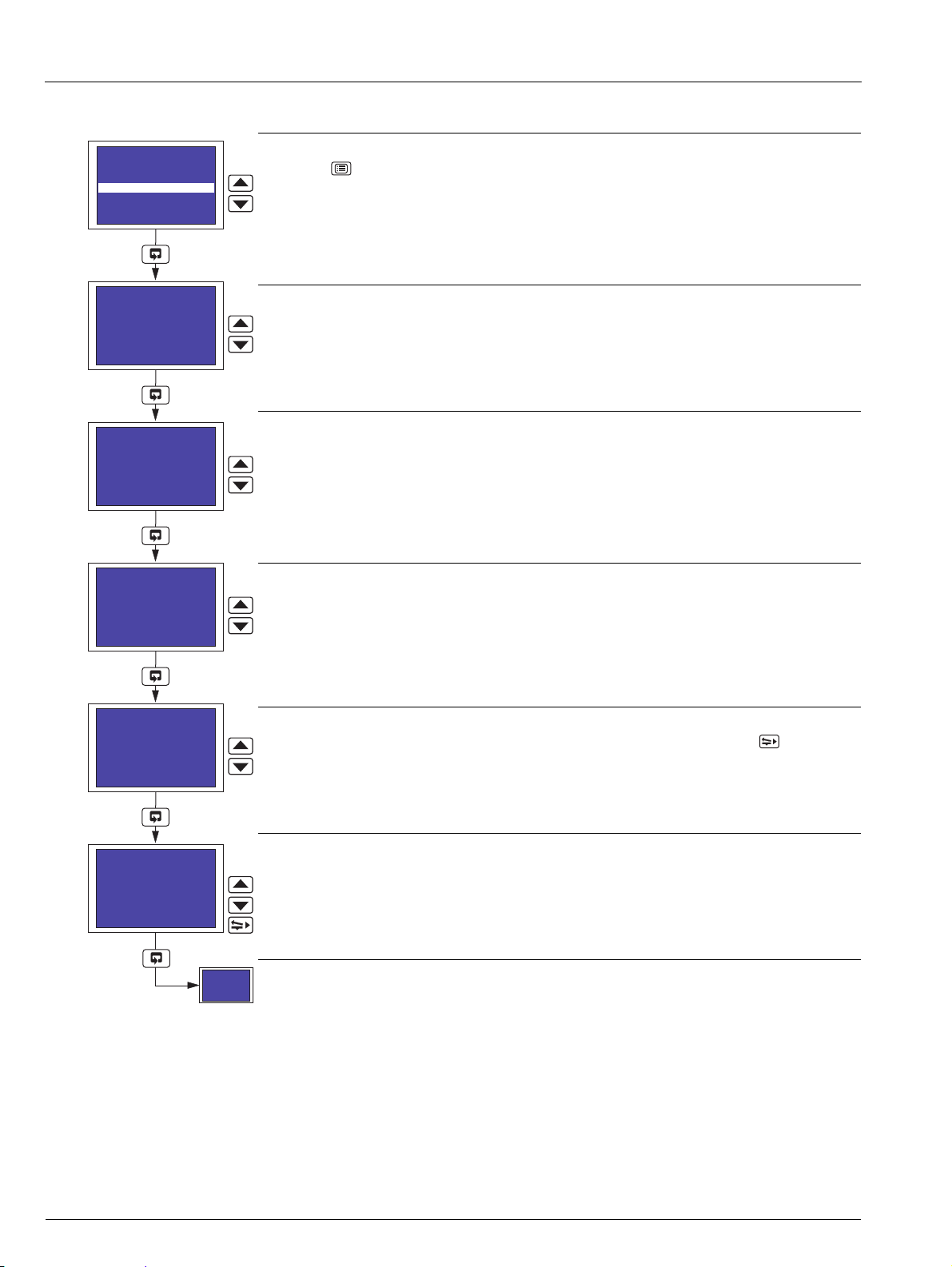
Advanced circular chart recorder 3 Configuration
Channels Configuration
Press the key to open the Main Menu.
Highlight Channels.
Select Channel
Select the channel to configure.
Note. If Pen X Function or Pen X Source (where X is the pen number) is set to Off or None
respectively (Section 3.14), that pen cannot be selected.
Pen X Function set to Tre nd (Section 3.14) – continued on next page.
Pen X Function set to Event (Section 3.14) – continued on page 30.
IM/C1300 Rev. J 25
Page 28

C1300
Select Channel
Pen 1
Pen 1 Tag
Input 1
Edit>
Pen 1 Input Type
High Ohm
Pen 1 Lin. Type
Type K
Pen 1 Units
101 mV
Pen X Function
set to Trend
(Section 3.13)
Millivolt
Milliamp
High Ohm
Low Ohm
Volts
Thermocouple
Rtd
None
Advanced circular chart recorder 3 Configuration
Channel Tag
Press the key to open the Edit screen.
Use the , and keys to enter the channel tag required – see Fig. 2.1 on page 6.
Note. Any characters not permitted in this tag are skipped when scrolling through the selection.
Press the key to close the edit screen and save the tag.
Channel Input Type
Select the required channel input type:
None –None
Millivolt – Millivolt (150mV)
Milliamp – Current
High Ohm – High resistance (>750)
Low Ohm – Low resistance (750)
Volts – Voltage
Thermocouple – Thermocouple
Rtd – Resistance thermometer
Return to top of page.
Linearizer Type
Select the required linearizer type.
None – No linearizer
Type K – Type K thermocouple
Type R – Type R thermocouple
Type S – Type S thermocouple
Type T – Type T thermocouple
Type J – Type J thermocouple
Type E – Type E thermocouple
Type N – Type N thermocouple
Type B – Type B thermocouple
Rtd – Resistance thermometer
Square Root – Square root
3/2 –X
5/2 –X
3/2
(Open channel flow applications)
5/2
(Open channel flow applications)
Continued on next page.
26 IM/C1300 Rev. J
Page 29

C1300
Pen 1 Units
101 mV
Pen 1 Elect. Hi
150.0 mV
Pen 1 Elect. Lo
40.0 mV
Pen 1 Dec. Point
XXX.XX
Pen 1 Eng. Hi
010.00 mV
Input Type
set to
Thermocouple
or RTD
Advanced circular chart recorder 3 Configuration
Channel Units
Select any of the units pre-programmed into the recorder or select 113 Custom and the ,
and keys to enter the units required – see Fig. 2.1 on page 6.
Notes.
Any characters not permitted in user-defined units are skipped when scrolling through the
selection.
Refer to Appendix B on page 78 for a description of the units pre-programmed into the
recorder.
Electrical Input Range High
Set the maximum electrical input value required, within the limits shown in Table 3.1.
Electrical Input Range Low
Set the minimum electrical input value required, within the limits shown in Table 3.1.
Decimal Point
Select the decimal point position for the engineering and chart ranges.
Continued on next page.
Input Type Electrical Range Low Electrical Range High Minimum Span (Low to High)
Millivolts 0 150 5.0
Milliamps 0 50 1.0
Resistance (High) 0 9999 400
Resistance (Low) 0 750 20
Volts 0 5 0.1
Table 3.1 Limits of Electrical Ranges
IM/C1300 Rev. J 27
Page 30

C1300
Pen 1 Eng. Hi
010.00 mV
Pen 1 Eng. Lo
000.00 mV
Pen 1 Chart Hi
010.00 mV
Pen 1 Brk Sensor
Downscale
Pen 1 Chart Lo
000.00 mV
Advanced circular chart recorder 3 Configuration
Engineering Range High
Set the maximum engineering value required, within the limits shown in Table 3.2.
Engineering Range Low
Set the minimum engineering value required, within the limits shown in Table 3.2.
Chart Range High
Set the maximum value, in engineering units, required on the chart.
Note. If the Engineering Range High setting is changed, the Chart Range High setting is reset
automatically to the same value.
Chart Range Low
Set the minimum value, in engineering units, required on the chart.
Note. If the Engineering Range Low setting is changed, the Chart Range Low setting is reset
automatically to the same value.
Continued on next page.
Linearizer Type Minimum Maximum Minimum Span Minimum Maximum Minimum Span
Type K –100 1300 65 –148 2372 117
Types R & S –18 1700 320 0 3092 576
Type T –250 300 60 –418 572 108
Type J –100 900 50 –148 1652 90
Type E –100 900 45 –148 1652 81
Type N –200 1300 90 –328 2372 162
Type B –18 1800 710 0 3272 1278
Rtd –200 600 25 –328 1112 45
Performance accuracy is not guaranteed below 400°C (725°F) for types B, R and S thermocouples.
Minimum span below zero for Type T thermocouples is 70°C (126°F).
Minimum span below zero for Type N thermocouples is 105°C (189°F).
THC standard DIN 4730 IEC 584.
RTD standard DIN 43760 IEC 751.
Linearizer Type Minimum Maximum
Square Root
3/2
5/2
None
Table 3.2 Limits of Engineering Ranges
Degrees Celsius Degrees Fahrenheit
Engineering Range High and Low
–999 9999
28 IM/C1300 Rev. J
Page 31

C1300
Pen 1 Brk Sensor
Downscale
Pen 1 Fault Lev.
10 %
Pen 1 Filter
Off
Select Channel
Pen 1
Advanced circular chart recorder 3 Configuration
Broken Sensor Protection Drive
In the event of an input failure, the process variable is driven in the direction selected:
Downscale – Process variable driven below zero
None – Process variable driven in direction of failure
Upscale – Process variable driven beyond full scale
Fault Detection Level Percentage
Set a tolerance level, between 0 and 100% of the engineering range, to allow for deviation of the
input signal above or below the input span before an input failure is detected.
Example – setting the fault detection level to 10% on input range of 50 (Engineering Range
Low) to 250 (Engineering Range High) bar causes an analog input failure fault to be detected
below 30 bar and above 270 bar.
Notes.
On some ranges the input circuitry may saturate before the fault level setting is reached. In
this case, an error is detected below the level set.
If an input exceeds the minimum or maximum value for the selected linearizer, an error is
detected regardless of the fault level setting.
Pen Filter
Filters the process variable input, i.e. if the input is stepped it smooths the transition between
steps and may also be used for some degree of cleaning of noisy inputs. The filter time
represents the time a step in the input takes to change the displayed process variable from 10 to
90% of the step.
Set the value required, between Off and 60 seconds in 1 second increments.
Return to top of page.
IM/C1300 Rev. J 29
Page 32

C1300
Pen 1 Off Tag
Pen 1 Event Off
Edit>
Pen 1 In Tag
Pen 1 Event In
Edit>
Pen 1 Out Source
None
Select Channel
Pen 1
Pen X Function
set to Event
(Section 3.13)
Pen 1 Out Tag
Pen 1 Event Out
Edit>
Pen 1 In Source
None
Advanced circular chart recorder 3 Configuration
Pen Off Tag
Press the key to open the Edit screen.
Use the , and keys to enter the pen off tag required – see Fig. 2.1 on page 6.
Note. Any characters not permitted in this tag are skipped when scrolling through the selection.
Press the key to close the edit screen and save the tag.
Pen In Tag
Press the key to open the Edit screen.
Use the , and keys to enter the pen in tag required – see Fig. 2.1 on page 6.
Note. Any characters not permitted in this tag are skipped when scrolling through the selection.
Press the key to close the edit screen and save the tag.
Pen Out Tag
Press the key to open the Edit screen.
Use the , and keys to enter the pen out tag required – see Fig. 2.1 on page 6.
Note. Any characters not permitted in this tag are skipped when scrolling through the selection.
Press the key to close the edit screen and save the tag.
Pen In Source
Select a digital source to move the pen inwards on the chart.
Refer to Appendix A on page 77 for a description of sources.
Pen Out Source
Select a digital source to move the pen outwards on the chart.
Refer to Appendix A on page 77 for a description of sources.
Return to top of page.
30 IM/C1300 Rev. J
Page 33

C1300
High Process
Low Process
Process
Variable
Hysteresis
Hysteresis
Trip Point
Alarm On
Alarm Off
Alarm On
Alarm Off
Output
Alarm Trip Point
Alarm On
Alarm Off
Time in seconds
Counter
Started
Counter
Reset
Counter
Started
Hysteresis Time
Elapsed
Counter
Reset
40 00
70 130
Time Hysteresis Status
Example shows time hysteresis set to 70 seconds used with a high process alarm
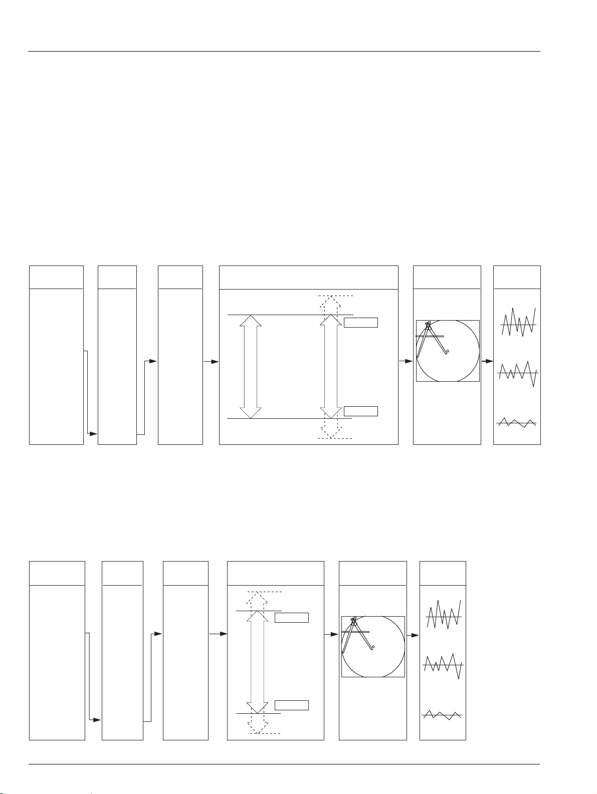
Advanced circular chart recorder 3 Configuration
3.6 Alarms Configuration
Overview.
Four alarms per channel – identified A1 to D1 (for channel 1) up to A4 to D4 (for channel 4).
High/Low process alarms.
Fast/Slow rate alarms.
Adjustable hysteresis value – prevents oscillation of alarm state.
Time hysteresis – enables delayed triggering of alarms.
Fig. 3.1 High and Low Process Alarm with Hysteresis
Fig. 3.2 Time Hysteresis Alarm
IM/C1300 Rev. J 31
Page 34

C1300
Alarm On
Alarm Off
Falling Fast Rate
Alarm On
Alarm Off
Rising Fast Rate
10.1
1 hour
1 hour
9.5
1 hour
9.5
T T
1 hour
10.1
T T
The maximum time it takes to detect an alarm condition is
present (T), in seconds, is calculated as follows:
T = 10.81 + x 2
The time it takes for the alarm state to be cleared once the
alarm condition has been removed is also equal to T.
Examples shown are for a trip value of 10%/hour on a PV engineering range of 0.0 to 100.0
1800
Trip Value
T = 10.81 + x 2
1800
10
T=382 seconds
The maximum time it takes to detect an alarm condition is
present (T), in seconds, is calculated as follows:
T = 10.81 + x 2
The time it takes for the alarm state to be cleared once the
alarm condition has been removed is also equal to T.
10.1
Examples shown are for a trip value of 10%/hour on a PV engineering range of 0.0 to 100.0
Alarm On
Alarm Off
Falling Slow Rate Rising Slow Rate
1 hour
9.5
T
Alarm On
Alarm Off
1800
Trip Value
1 hour
10.1
1 hour
9.5
1 hour
T T T
T = 10.81 + x 2
1800
10
T=382 seconds
Advanced circular chart recorder 3 Configuration
Fig. 3.3 Fast Rate Alarms with Hysteresis
Fig. 3.4 Slow Rate Alarms with Hysteresis
32 IM/C1300 Rev. J
Page 35

C1300
Select Alarm
A1
Alarm Setpoints
Security Code
Common
Channels
Alarms
Totalizers
Relays
Digital I/O
A1 Type
Off
A1 Trip
000.00 mV
Off
Advanced circular chart recorder 3 Configuration
Alarms Configuration
Press the key to open the Main Menu.
Highlight Alarms.
Select Alarm
Select the alarm to be configured.
Alarm Type
Select the alarm type required:
Off – No alarm
High Process – See Fig. 3.1 on page 31
Low Process – See Fig. 3.1 on page 31
Fast Rate – See Fig. 3.3 on page 32
Slow Rate – See Fig. 3.4 on page 32
Continued on next page.
IM/C1300 Rev. J 33
Page 36

C1300
A1 Trip
000.00 mV
A1 Hysteresis
000.00 mV
A1 Time Hyst
0000 Secs
Select Alarm
A1
Advanced circular chart recorder 3 Configuration
Trip L e v e l
Set the value at which the alarm is to activate.
For High and Low Process alarms, the value is set in engineering units.
For Fast and Slow Rate alarms, the trip level is set as a percentage of the engineering span
(engineering range high – engineering range low) per hour, between 500 and 500% in 0.1%
increments.
Hysteresis
Set the hysteresis value, either in engineering units (High and Low Process alarms) or as a
percentage of the engineering span (Fast and Slow Rate alarms).
Hysteresis is operational only when the alarm is active. The alarm is activated at the trip level but
is de-activated only after the alarm variable has moved into the safe region by an amount equal to
the hysteresis value. For rate alarms this setting is a percentage of the trip level.
Time Hysteresis
Set the time hysteresis value required, between 0 and 9999 seconds.
If a Time Hysteresis value is set, the alarm becomes active only when the alarm condition is
present continuously for the time set.
If a Hysteresis value is also set (see above) and an alarm is activated, the alarm remains active
until the process variable moves outside the hysteresis band. When the alarm condition no longer
exists the alarm becomes inactive immediately, i.e. time hysteresis does not affect turning off of
alarm states.
Return to top of page.
34 IM/C1300 Rev. J
Page 37

C1300
Advanced circular chart recorder 3 Configuration
3.7 Totalizer Configuration
Overview.
Up to four, 9-digit totalizers – assignable to any pen, analog input or math block (if math software option enabled by
installation of the appropriate software key).
Count up or count down.
Automatic count rate calculation – wherever possible, the recorder calculates the count rate automatically according to
source units, totalizer units and engineering range, from 0.0001 to 99.9999 counts/second.
External counter pulse – can be used to energize relays or digital outputs (a maximum of 4 pulses per second are generated).
Wrap function – with external wrap pulse used to energize relays or digital outputs.
Programmable preset and predetermined count values – for (batch) flow total.
Adjustable cut-off values.
Operator level reset and stop/go.
Digital signal reset and stop/go.
When enabled by installation of the appropriate software key, the totalizer software provides indication and recording of flow rates
from input signals with linear, square law or power law characteristics. Totalization is available for each channel and can be switched
on or off as required.
The flow total for any channel can be viewed on the same display screen as the input (pen) channel to which it is assigned. The flow
total can also be reset using the control keys on the associated faceplate. An additional internal 'Secure' total is also provided that
can be reset only in the Totalizer Configuration level.
External counters with their own power supplies can be driven using 4 relay and digital output module options.
Count Rate
Totalizers are normally used in flow applications and their purpose is to summate the volume of process fluid passing the point of
measurement. Totalizers have no relationship to time and continue to count up or down (dependant on setting) until instructed to
reset. A trip meter on a typical family car is an example of a basic totalizer – the meter counts and displays the distance travelled by
the vehicle until reset by the driver. In this example, the speedometer and trip meter read in the same unit of distance.
Flow totalization is more complex than that of a trip meter. In flow totalization, the flow recorder typically measures the instantaneous
value in one flow unit whilst the totalizer counts in a larger flow unit. When configuring a totalizer, a count rate must be calculated and
entered to compensate for the difference between the totalized measurement unit and the instantaneous measurement unit.
Where possible, the recorder calculates automatically the count rate for the most popular measurement units, e.g. gallons, cubic feet,
liters and cubic meters. When configuring a totalizer, first ensure that the unit of measurement (Channel Units) selected for the
channel to which the totalizer is assigned is a volumetric unit (i.e. quantity per unit of time, for example gallons per hour) – see Section
3.5, page 24. Finally, enter the required Totalizer unit of measurement. If the recorder holds the relationship data between th
e selected
measurement and totalizer units, 'Automatic' is displayed under the count rate to indicate that it has been set automatically. If the
relationship data is not in the recorder's look-up table, 'Manual' is displayed and the count rate must be set manually – see next
page.
IM/C1300 Rev. J 35
Page 38

C1300
Volume relationship
Full scale flow
--------------------------------------------------
number of seconds in time-base Seconds to pass one totalizer unit=
6.229 (imperial gallons in 1ft3
300 (imperial gallons max. flow rate)
------------------------------------------------------------- -------------------------------
60 (seconds in 1 minute) 1.2458 seconds to pass 1ft
3
=
1
Seconds to pass 1 totalizer unit
------------------------------------------------------------- --------------------- - Totalizer count rate=
1
1.2458
------------------ 0.803=
Advanced circular chart recorder 3 Configuration
Calculating The Count Rate Manually
The count rate determines how many units the totalizer increments per second when the flow input signal is at 100%. To calculate
this parameter manually, follow the procedure below:
1. Calculate the volume relationship
Typically the unit of measure used by the totalizer is larger than that used for displaying the instantaneous flow-rate. Use
standard conversion tables to calculate how many times the flow units used for the input will fit into the desired totalizer unit.
Example: Measurement channel units is set to gallons/minute. Instantaneous process flow-rate (engineering range) is 0-300
imperial gallons/minute, totalizer is required to increment in cubic feet. From standard conversion tables, 1 cubic foot = 6.229
imperial gallons.
2. Calculate the unit time
Ensuring that the time-base of the instantaneous flow-rate is used, the following equation determines how many seconds it will
take at full scale flow for a single totalizer unit to pass the measurement point:
Example:
3. Calculate the count rate
The totalizer count rate is the reciprocal of the result of the calculation above:
Example:
36 IM/C1300 Rev. J
Page 39

C1300
Select Totalizer
T1 Configuration
Security Code
Common
Channels
Alarms
Totalizers
Relays
Digital I/O
Retransmission
Tot 1 Source
Pen 1
Tot 1 Tag
Totalizer 1
Edit>
Secure Total 1
000000000
gal
None
T(1 to 4)
Configuration
T(1 to 4)
Secure Total
Advanced circular chart recorder 3 Configuration
Note. Totalizer configuration is available only if the totalizer software option is enabled by installation of the appropriate software
key.
Totalizers Configuration
Press the key to open the Main Menu.
Highlight Totalizers.
Select Totalizer
Select the totalizer to be configured.
Continued on page 41.
Totalizer Source
Select the source for the totalizer.
Note. Any of Pens 1 to 4, Analog Inputs 1 to 6 or Math Blocks 1 to 4 (if Math software option is
enabled by installation of the appropriate software key) are assignable to a totalizer.
Continued on next page.
IM/C1300 Rev. J 37
Page 40

C1300
Tot 1 Tag
Totalizer 1
Edit>
Tot 1 Count Dir
Up
Tot 1 Count Rate
00.0000
Manual
Tot 1 Units
18 gal/h
(Imp)
Advanced circular chart recorder 3 Configuration
Totalizer Tag
Press the key to open the Edit screen.
Use the , and keys to enter the totalizer tag required – see Fig. 2.1 on page 6.
Note. Any characters not permitted in this tag are skipped when scrolling through the selection.
Press the key to close the edit screen and save the tag.
Count Direction
Select the count direction:
Up – Incremental counter (Preset Value < Predetermined Value)
Down – Decremental counter (Preset Value > Predetermined Value)
Totalizer Units
Select any of the units pre-programmed into the recorder or select 113 Custom and use the
, and keys to enter the units required – see Fig. 2.1 on page 6.
Notes.
Any characters not permitted in user-defined units are skipped when scrolling through the
selection.
Refer to Appendix B on page 78 for a description of the units pre-programmed into the
recorder.
Continued on next page.
38 IM/C1300 Rev. J
Page 41

C1300
Tot 1 Count Rate
00.0000
Manual
Tot 1 Cut Off
0000.0 gal/h
Tot 1 Preset
000005000
gal/h
Tot 1 Wrap
YES
Tot 1 Predet
000004500
gal/h
Advanced circular chart recorder 3 Configuration
Totalizer Count Rate
Automatic – the recorder has calculated the count rate automatically. No further
adjustment is possible.
Manual – the count rate must be calculated manually (see page 36). Use the ,
and keys to enter the calculated count rate in pulses per second, from
00.0000 to 99.9999 in 0.0001 increments.
Note. To configure the totalizer for Automatic count rate calculation:
1. Ensure that the unit of measurement (Channel Units) selected for the channel to which the
totalizer is assigned is a volumetric unit (i.e. quantity per unit of time, for example gallons
per hour) – see Section 3.5, page 24.
2. Enter the required Totalizer unit of measurement (Totalizer Units) – see previous page.
If the recorder holds the relationship data between the selected measurement and totalizer units,
Automatic is displayed under the count rate to indicate that it has been set automatically.
Totalizer Cut Off
Set the value, in engineering units, at which the totalizer is to stop counting.
Totalizer Preset Value
Set the value, in engineering units, from which the totalizer is to start counting and the value that
is applied when the totalizer is reset.
Totalizer Predetermined Value
Set the value, in engineering units, at which the totalizer stops or wraps.
Continued on next page.
IM/C1300 Rev. J 39
Page 42

C1300
Tot 1 Wrap
YES
Tot 1 Reset Srce
None
Tot 1 Reset Days
Monday
Tot 1 Reset Hour
00:00
Tot 1 Run Source
None
Tot 1 Run Source
None
Timed
Advanced circular chart recorder 3 Configuration
Totalizer Wrap
Select the required totalizer wrap action:
YES – the total is reset automatically to the preset value when the predetermined value is
reached.
NO – the count stops when the predetermined value is reached
Totalizer Reset Source
If required, select a digital signal to reset the totalizer or select Timed to configure the totalizer to
reset at a predetermined time.
Refer to Appendix 1 for description of sources.
Anything other than Timed selected – continued on next page.
Totalizer Reset Day
Select the day or days on which the totalizer is to reset:
Monday to Sunday – the totalizer resets on the day selected
Mon-Fri – the totalizer resets every Monday to Friday inclusive
All – the totalizer resets every day
1st of Month – the totalizer resets on the 1st day of every month
Totalizer Reset Time
Select the time of day at which the totalizer is to reset, from 00:00 (midnight) to 23:00 (11 pm) in
1 hour increments.
Continued on next page.
40 IM/C1300 Rev. J
Page 43

C1300
T1 Secure Reset
NO
Select Totalizer
T1 Secure Total
Select Totalizer
set to
T1 Secure Total
Tot 1 Run Source
None
Tot 1 Log Enable
None
Select Totalizer
T1 Configuration
Secure Total 1
000000000
gal
Tot 1 Log Start
00:00
None
Prior to reset
12 hours
24 hours
Select Totalizer
T1 Configuration
Advanced circular chart recorder 3 Configuration
Totalizer Run Source
If required, select a digital signal to start the totalizer.
Refer to Appendix A on page 77 for a description of sources.
Totalizer Log Enable Source
If required, select the frequency at which the addition of the current totalizer values to the totalizer
log is triggered:
None – current totalizer values are not added to the totalizer log
Prior to reset – current totalizer values are added as the totalizer resets
12 hours – current totalizer values are added every 12 hours
24 hours – current totalizer values are added every 24 hours
Return to top of page.
Totalizer Log Start Time
Enter the time at which logging is to start.
Return to top of page.
Totalizer Secure Total
Secure Total Reset
Select YES to reset the secure total.
The secure total is reset to either 000000000 (Count Direction set to Up) or 999999999 (Count
Direction set to Down).
IM/C1300 Rev. J 41
Return to top of page.
Page 44

C1300
Relay SourceSelect Relay Output
Logic Equation 1
Logic Equation 8
Digital Input 1
Digital Input 2
Alarm A1
Alarm D4
None
Polarity Selection
Relay 5.1
Relay 5.2
Relay 5.3
Relay 5.4
Module Position
Relay No.
Alarm A1
Active
Energized
Positive
Alarm A1
Active
De-energized
Negative
Alarm A1
Inactive
Positive
Alarm A1
Inactive
Energized
Negative
De-energized
Relay Contacts
NC
C
NO
NC
C
NO
NC
C
NO
NC
C
NO
Source State Polarity Relay State
Select Relay
Relay 1.1
Common
Channels
Alarms
Totalizers
Relays
Digital I/O
Analog Output
Modbus
Relay 1.1 Source
Alarm A1
Rly 1.1 Polarity
Negative
Select Relay
Relay 1.1
None
Advanced circular chart recorder 3 Configuration
3.8 Relay Configuration
Overview.
Relays – can be energized by alarms, logic equation results (math software option enabled by installation of the appropriate
software key), digital inputs, real time events (timer software option enabled by installation of the appropriate software key) and
totalizer wrap signal (totalizer software option enabled by installation of the appropriate software key)
External totalizer count function – external counter can be driven only by Module Type 3 (4-relay module) fitted in module
positions 4, 5 or 6 (see Section 5.2, page 66).
Polarity – allows fail-safe settings
Relay Configuration
Press the key to open the Main Menu.
Highlight Relays.
Select Relay
Select the relay to be configured.
Relay Source
Select the source required to activate the selected relay.
Refer to Appendix A on page 77 for a description of sources.
42 IM/C1300 Rev. J
Relay Polarity
Select the polarity required for the selected relay:
Positive – relay is energized when the relay source is active (On)
Negative – relay is energized when the relay source is inactive (Off)
Return to top of page.
Page 45

C1300
Digital Input 1
Active
Positive
Energized
Negative De-energized
Positive
Energized
Negative
De-energized
Digital Input 1
Active
Digital Input 1
Inactive
Digital Input 1
Inactive
Polarity Selection
Source State Polarity Output StateDigital Source
Logic Equation 1
Logic Equation 4
Digital input 1
Digital input 2
Alarm A1
Alarm D4
None
Select Digital Output
Output 5.1
Output 5.2
Output 5.3
Output 5.4
Output 5.5
Output 5.6
Output 5.7
Output 5.8
Module Position
Output No.
Select Dig I/O
Output 6.1
Channels
Alarms
Totalizers
Relays
Digital I/O
Analog Output
Modbus
Math Blocks
Dout 6.1 Source
Alarm A1
Din 1.x Polarity
Positive
Advanced circular chart recorder 3 Configuration
3.9 Digital Input and Output Configuration
Overview.
The Digital I/O menu selection is displayed only if a digital input/output module is fitted – see Section 5.3.3, page 70.
Up to 24 digital outputs available – depending on the module types fitted.
Digital outputs – can be energized by alarms, logic equation results (math software option enabled by installation of the
appropriate software key), digital inputs, real time events (timer software option enabled by installation of the appropriate
software key) and totalizer wrap signal (totalizer software option enabled by installation of the appropriate software key).
External Totalizer count function – external counter can be driven only by Module Type 5 (8-digital output module) fitted in
module positions 4, 5 or 6 (see Section 5.2, page 66).
Polarity – inverts the effect of the selected source on the output state.
Digital I/O Configuration
Press the key to open the Main Menu.
Highlight Digital I/O.
Select Digital Input/Output
Select the digital input or output to be configured.
Output X.X selected – continued on next page.
Input X.X selected – continued on next page.
IM/C1300 Rev. J 43
Page 46

C1300
Dout 6.1 Source
Alarm A1
Dout6.1 Polarity
Positive
Select Dig I/O
Input 1.x
Din 1.x Polarity
Positive
Select Dig I/O
Input 1.x
Select Dig I/O
set to
Output X.X
Select Dig I/O
set to
Input X.X
Advanced circular chart recorder 3 Configuration
Digital Output Source
Select the channel source for the digital output.
Refer to Appendix A on page 77 for a description of sources.
Digital Output Polarity
Select the polarity required for the selected digital output:
Positive – digital output is energized when the relay source is active (On)
Negative – digital output is energized when the relay source is inactive (Off)
Return to top of page.
Digital Input Polarity
Select the polarity required for the selected digital input:
Positive – digital output state is unchanged
Negative – digital output state is inverted
Return to top of page.
44 IM/C1300 Rev. J
Page 47

C1300
4.0mA (Output Range Low)
20.0mA (Output Range High)
1000°C (Engineering Range High)
Select Output
Source
Setting Output Ranges
PV1
PV2
PV3
PV4
0°C (Engineering Range Low)
Range to be
transmitted
750°C (Analog Output Range High)
250°C (Analog Output Range Low)
Select Analog
Output
Position 1
Positiont 6
Select Output
Analog Output 1
Alarms
Totalizers
Relays
Digital I/O
Analog Output
Modbus
Math Blocks
Logic Equations
O/P1 Source
Pen 1
None
O/P1 Range High
010.00 mV
Advanced circular chart recorder 3 Configuration
3.10 Analog Output Configuration
Overview.
Fitted analog outputs – assignable to retransmit any process variable
Selectable analog output range – allows maximum resolution on range of interest
Adjustable output range – for non-standard and reversed outputs
The example below shows analog output 1 programmed to retransmit part of process variable 1's engineering range (250 to 750°C)
as a 4.0 to 20.0 mA current output.
Analog Output Configuration
Press the key to open the Main Menu.
Highlight Analog Output.
Select Analog Output
Select the analog output to be configured.
Analog Output Source
Select the source for the analog output.
Refer to Appendix A on page 77 for a description of sources.
Continued on next page.
IM/C1300 Rev. J 45
Page 48

C1300
O/P1 Range High
010.00 mV
O/P1 Range Low
000.00 mV
O/P1 Elect High
020.0 mA
O/P1 Elect Low
004.0 mA
Select Output
Analog Output 1
Advanced circular chart recorder 3 Configuration
Analog Output Range High
Set the engineering range value, in engineering units, at which maximum output is required.
Analog Output Range Low
Set the engineering range value, in engineering units, at which minimum output is required.
Analog Electrical Range High
Set the maximum current output value to correspond with the Analog Output Range High,
between 0.0 and 20.0 mA in 0.1 mA increments.
Analog Electrical Range Low
Set the minimum current output value to correspond with the Analog Output Range Low,
between 0.0 and 20.0 mA in 0.1 mA increments.
Return to top of page.
46 IM/C1300 Rev. J
Page 49

C1300
Logic
Inputs
Equation 1.1
Equation 1.3
Equation 1.2
Equation 1.5
Equation 1.7
Result
Equation 1.4
Equation 1.6
AND
OR
XOR
NAND
NOR
AND
OR
XOR
NAND
NOR
AND
OR
XOR
NAND
NOR
Advanced circular chart recorder 3 Configuration
3.11 Logic Equation Configuration
Overview.
8 logic equations
Up to 4 operands and 3 operators per equation
OR/AND/XOR/NAND/NOR/NOT operators
Can combine internal and external digital signals – i.e. alarms, digital inputs, other logic equation results and real-time
events (if timer software option enabled by installation of the appropriate software key)
For each equation, the logic elements 1 to 7 are arranged sequentially, as shown below. Odd numbered elements are used for logic
inputs (operands) and even numbered elements for logic gates (operators).
Logic inputs must be set to one of the digital sources in Appendix A on page 77.
Logic inputs may be inverted (set to NOT)
Logic gates must be set to AND, OR, XOR, NAND, NOR or END. Setting an element to END terminates the equation.
Note. The elements of each equation are calculated sequentially, i.e. elements 1, 2 and 3 are evaluated first and the result
combined with elements 4 and 5. This result is then combined with elements 6 and 7 to give the logic equation result.
IM/C1300 Rev. J 47
Page 50

C1300
Equation 1.1
Equation 1.2
Equation 1.3
Equation 1.4
Equation 1.5
Equation 1.6
Equation 1.7
Entering the Logic Equation
Alarm A1
AND
Alarm C1
OR
Alarm B1
OR
Digin Main 1
Alarm A1 set to high process trip at 50 ft
Alarm B1 set to high process trip at 80 ft
Alarm C1 set to fast rate trip at 10% of
range per hour (10 ft/hr)
Manual override switch:
Connected to digital input 1.1
Digital input number
Module number
Negative polarity
Volt-free switching
Input Elements
Flow Conditions
Close reservoir control valve if:
Reservoir level >50 feet AND
rate of change >10 ft/hr
OR
Reservoir level >80 ft
OR
Manual override switch operated
50
feet
80
feet
Control
Valve
Level Sensor
Relay Output
Manual Overide
Alarm B1
Alarm A1
Time
Level
Alarm C1
Rate of
change
> 10ft/h
Advanced circular chart recorder 3 Configuration
Example – Reservoir level monitoring using:
process variable 1 with an engineering range of 0 to 100 feet
logic equation 1 result assigned to relay 1.1 that is used to operate the control valve.
48 IM/C1300 Rev. J
Page 51

C1300
Select Equation
Equation 1
Relays
Digital I/O
Analog Output
Modbus
Logic Equations
Data Logging
Clock
Pen Function
Equation 1.1
Alarm A1
Invert>
Equation 1.2
AND
Equation 1.3
NOT Digin Main 1
Invert>
Select Equation
Equation 1
NONE
Advanced circular chart recorder 3 Configuration
Logic Equation Configuration
Press the key to open the Main Menu.
Highlight Logic Equations.
Select Equation
Select the equation to be configured.
Equation n/Element 1
Select the source required for element 1.
Refer to Appendix A on page 77 for a description of sources.
Press the key to logically invert the selected source (set to NOT)
Equation n/Element 2
Select the operator required to combine elements 1 and 3:
END – Ends equation
AND – Output is 1 if both inputs are 1, but 0 for all other possible inputs
OR – Output is 1 if one or the other or both inputs are 1, but 0 if both inputs are 0
XOR – Output is 1 if either, but not both, inputs are 1, but 0 if both inputs are 0 or 1
NAND – Output is 0 if both inputs are 1, but 1 if one or the other or both inputs are 0
NOR – Output is 1 if both inputs are 0, but 0 if one or the other or both inputs are 1
Equation n/Element 3
Repeat previous two steps for elements 3 to 7.
Odd numbered elements = operands
Even numbered elements = operators
Return to top of page.
IM/C1300 Rev. J 49
Page 52

C1300
Advanced circular chart recorder 3 Configuration
3.12 Data Logging Configuration
Note. The data logging option is no longer available. Data logging information has been retained in this publication for reference
purposes only.
Trend pen channel data values and the contents of the totalizer log (if the totalizer option is enabled by installation of the appropriate
software key) can be saved to a Compact Flash card if the optional data logging hardware is installed and data logging is on-line.
Logged data is compatible with the Company's DataManager data analysis software package. DataManager is a Microsoft® Excel
add-in that enables the analysis and validation of the recorder's pen channel data values and log files on a PC.
Note.
The recorder is not equipped with an internal memory therefore recorded pen channel data values are lost if a Compact
Flash card with sufficient available free space is not inserted.
Logging starts automatically when a card is inserted and continues until either the card is removed or becomes full.
The content of the totalizer log (if the totalizer option is enabled by installation of the appropriate software key) is saved
automatically to the Compact Flash card when data logging is on-line.
Event pen data is not logged.
File Types
Files created by the recorder are given filenames automatically. Each type of file is given a different filename extension as shown in
Table 3.3.
Ty pe Extension Contents
Pen channel data files *.D00 Digital recording channel data
Totalizer log files *.TE0 The historical record of all totalizer and associated statistical values relating to a particular pen channel
Table 3.3 File Types
Filenames
Filenames are formatted as shown in Table 3.4.
Ty pe Format
Pen channel data files <Start Time hh_mm> Start Date ddmmmyy><Instrument tag>.D00
Totalizer log files <Start Time hh_mm> Start Date ddmmmyy><Instrument tag>.T00
Table 3.4 Filenames
Data Verification and Integrity
Each block of data in the pen channel data files has its own data integrity check. This enables the integrity of the data stored on the
Compact Flash card to be verified when it is viewed using the DataManager software.
Totalizer log files also contain built-in integrity checks enabling the integrity of the data to be verified by the DataManager software.
50 IM/C1300 Rev. J
Page 53

C1300
Advanced circular chart recorder 3 Configuration
Recording Duration
(4 Channels) 128MB 256MB 512MB 1GB
1 s 1.1 months 2.3 months 4.5 months 8.8 months
5 s 5.6 months 11.3 months 1.9 years 3.6 years
10 s 11.3 months 1.9 years 3.7 years 7.2 years
30 s 2.8 years 5.6 years 11.1 years 21.7 years
60 s 5.6 years 11.1 years 22.2 years 43.4 years
5 min. 27.8 years 55.5 years 111.0 years 216.8 years
10 min. 55.5 years 111.0 years 222.1 years 433.7 years
30 min. 166.5 years 333.1 years 666.2 years 1301.1 years
1 hour 333.1 years 666.2 years 1332.3 years 2602.2 years
6 hour 1998.5 years 3996.9 years 7993.9 years 15613.1 years
Table 3.5 Recording Duration
Note. Data Logging is available only if the Data Logging option is enabled by installation of the optional hardware.
IM/C1300 Rev. J 51
Page 54

C1300
Sample Rate
10 Seconds
Digital I/O
Analog Output
Modbus
Logic Equations
Data Logging
Clock
Pen Function
Calibration
Filter Type
Instantaneous
File Creation
On pen return
Instrument Tag
Boiler 1 Zone 3
Edit>
Pen 1 Short Tag
Pressure
Edit>
Advanced circular chart recorder 3 Configuration
Data Logging Configuration
Press the key to open the Main Menu.
Highlight Data Logging.
Sample Rate
Select the sample rate to be applied to all recording channels.
Select from:
1, 5, 10, 30 or 60 seconds
5, 10 or 30 minutes
1 or 6 hours
Pre-logging Filter Type
Select the filter type to be applied to all recording channels prior to logging.
Instantaneous–A single value based on process conditions at the time of sampling
Max/Min–Two values are recorded to capture the maximum and minimum signal values since
the previous sample
New File Creation
Select the interval at which new data logging files are created:
Standard–new files are created when:
a file becomes full (i.e. it has reached 65,000 entries)
or
the Compact Flash card is removed and re-inserted
or
power to the recorder is restored after being interrupted
or
the recorder's configuration is changed
On Pen Return–In addition to the Standard file creation intervals, new files are also created
when the pens are returned to their recording positions. This enables recorded files to match the
chart record.
Instrument Tag
Use the , and keys to enter a tag of up to 16 characters – see Fig. 2.1 on page 6.
Note. Any characters not permitted in this tag are skipped when scrolling through the selection.
The tag is included in the archive files to identify the source of the data.
Continued on next page.
52 IM/C1300 Rev. J
Page 55

C1300
Sample Rate
10 Seconds
Pen 1 Short Tag
Pressure
Edit>
Pen 4 Short Tag
Pressure
Edit>
Serial Number
A/4590321/221
Edit>
Advanced circular chart recorder 3 Configuration
Pen 1 Short Tag
Note. This tag is required to provide compatibility with the Company's DataManager data
analysis software package and is used to identify the column of data for Pen 1.
Use the , and keys to enter the a tag of up to 8 characters – see Fig. 2.1 on page 6.
Note. Any characters not permitted in this tag are skipped when scrolling through the selection.
The tag is included in the archive files to identify the channel.
Pens 2 to 4 Short Tag
Notes.
Displayed only if the pen is fitted.
These tags are required to provide compatibility with the Company's DataManager data
analysis software package and are used to identify the column of data for each pen.
Use the , and keys to enter the a tag of up to 8 characters – see Fig. 2.1 on page 6.
Note. Any characters not permitted in this tag are skipped when scrolling through the selection.
The tag is included in the archive files to identify the channel.
Serial Number
Use the , and keys to enter a serial number to be used to identify the recorder – see
Fig. 2.1 on page 6.
Note. Any characters not permitted in this tag are skipped when scrolling through the selection.
Return to top of page.
IM/C1300 Rev. J 53
Page 56

C1300
Digital I/O
Analog Output
Modbus
Logic Equations
Data Logging
Clock
Pen Function
Calibration
Set Clock
NO
Set Year
2004
System Time
Wednesday
26th May 2004
15:28:59
NO
Set Minute
15:28
Update - NO
Wednesday
26th May 2004
15:29:00
System Time
Wednesday
26th May 2004
15:29:07
Advanced circular chart recorder 3 Configuration
3.13 System Clock Configuration
Note. The System Clock is available only if any of the Totalizer, Math or Timers software options are enabled by installation of the
appropriate software key, or the optional Data Logging hardware is installed.
System Clock Configuration
Press the key to open the Main Menu.
Highlight Clock.
System Time
The current settings are displayed.
Set Clock
Select YES to set the system date and time.
Select NO to retain the current settings.
Set System Date and Time
Use the and keys to set each element of the date and time.
Press the key to move to the next element in the sequence.
Update Clock
Select YES to save the new system date and time.
Select NO to retain the current settings.
Return to top of page.
54 IM/C1300 Rev. J
Page 57

C1300
Select Pen Range (in engineering units)
0 (Eng. Range Low)
1000 (Eng. Range High)
Select 'In' Source Select 'Out' Source
700 (Pen Range High)
400 (Pen Range low)
*Source on
Source off
Source on
Source off
*In source takes priority if both
sources enabled
Record Function Event Function
Pen 2 at 40%
Pen 3 at 60%
Pen 1
at 20%
*Pen 4 at 80%
Event Pen Chart Position
*With Real Time Event Pen
option fitted, Pen 4 is above
100%
Digital I/O
Analog Output
Modbus
Logic Equations
Data Logging
Clock
Pen Function
Calibration
Pen 1 Function
Off
Pen 1 Source
None
Select Pen
Pen 1
Select Pen
Pen 1
Off
or
Event
Advanced circular chart recorder 3 Configuration
3.14 Pen Function
Overview.
Tren d P e ns – the chart range is configured independently of the engineering range (see Section 3.5, page 24) to enable a
selected part of the engineering range to be used for display thus giving extra detail on the chart.
Event Pens – assigned to digital inputs, alarms, logic equation results and real-time events (if timer software option enabled by
installation of the appropriate software key).
Pen Function
Press the key to open the Main Menu.
Highlight Pen Function.
Select Pen
Select the pen to configure.
Pen Function
Select the required pen function:
Off – No function
Trend –Trend
Event –Event
Pen Source
Select an input source or math block for the selected pen as required.
Return to top of page.
IM/C1300 Rev. J 55
Page 58

C1300
Digital I/O
Analog Output
Modbus
Logic Equations
Data Logging
Clock
Pen Function
Calibration
Reset Pen 1 Cal
NO
-999.89 mV
Pen 1 Offset
0.00
-999.89 mV
Select Cal
Pen 1 Input Cal
Pen 1 Span
0.9999
-992.66 mV
Select Cal
Pen 1 Input Cal
Set Pen 1 High
0
Pen X
Input Cal
Pen X
Chart Cal
Advanced circular chart recorder 3 Configuration
3.15 Calibration
Calibration
Press the key to open the Main Menu.
Highlight Calibration.
Select Cal
Select the pen input channel or pen chart position to calibrate.
Continued on next page.
Reset Pen Calibration
Select YES to reset the offset and span values to their nominal values.
Select NO to retain the current offset and span values.
Offset
Set the required offset value for the selected pen or analog input.
Span
Set the required span value for the selected pen or analog input.
Return to top of page.
56 IM/C1300 Rev. J
Page 59

C1300
Select Cal
set to
Pen X Chart Cal
Set Pen 1 High
0
Set Pen 1 Low
0
Select Cal
Pen 1 Chart Cal
Advanced circular chart recorder 3 Configuration
Pen High Value
Set the required chart high value for the selected pen, between 0 and 200.
Pen Low Value
Set the required chart low value for the selected pen, between 0 and 200.
Return to top of page.
IM/C1300 Rev. J 57
Page 60

C1300
Configurator Cable (part no. C100/0051)
Configuration Backup Port
Totalizer Log
Totalizer Control
Alarm Setpoints
Security Code
Common
Channels
Alarms
Totalizers
PC Config Mode
Press Menu to exit
Select the port to which
the configurator cable is
connected
1
3
Assign a name and location
to the configuration file to
be saved
Select 'Upload Config.'
radio button
2 4
Click to save the
configuration backup file
Click to save the
configuration backup file
6
The following is displayed when upload is
complete
Note. The following warning is displayed if an
incorrect port was selected in step or the
recorder is not connected correctly to the PC.
1
5
The following message is displayed
Advanced circular chart recorder 3 Configuration
3.16 Backing Up and Restoring Configurations
A backup file of the recorder's configuration settings can be
saved to a PC and restored to the recorder using the C1300
Configuration Backup Utility Software (download from
www.abb.com/recorders) and Configurator Cable (part no.
C100/0051 – available from the Company).
3.16.1 Backing Up a Configuration
1 Connect the Configurator Cable to the recorder's
configuration backup port (see Fig. 3.5) and the PC's serial
port.
Fig. 3.5 Configuration Backup Port
2 Press the key to
open the Main Menu.
3 Highlight Common (or
any of the Configuration
level selections below
Common).
4 Press the and
keys simultaneously to
place the recorder into PC
5 Run the software 'C1300 Configuration Backup Utility.exe'
on the PC.
6 Save the current configuration – see Fig. 3.6.
7 Exit the C1300 Configuration Backup Utility Software.
8 Disconnect the Configurator Cable.
9 Press the key to return the recorder to normal
Config Mode.
operation – see Section 2.3.1, page 8.
Fig. 3.6 Backing Up a Configuration
58 IM/C1300 Rev. J
Page 61

C1300
Totalizer Log
Totalizer Control
Alarm Setpoints
Security Code
Common
Channels
Alarms
Totalizers
PC Config Mode
Press Menu to exit
Select the port to which
the configurator cable is
connected
1
3
Select the configuration file
to be restored
Ensure 'Download Config.'
radio button selected
2 4
Click to restore the
configuration backup file
6
The following is displayed when upload is
complete
Note. The following warning is displayed if an
incorrect port was selected in step or the
recorder is not connected correctly to the PC.
1
5
The following message is displayed
Advanced circular chart recorder 3 Configuration
3.16.2 Restoring a Configuration
1 Connect the Configurator Cable to the recorder's
configuration backup port (see Fig. 3.5) and the PC's serial
port.
2 Press the key to
open the Main Menu.
3 Highlight Common (or
any of the Configuration
level selections below
Common).
4 Press the and
keys simultaneously to
place the recorder into PC
Config Mode.
5 Run the software 'C1300 Configuration Backup Utility.exe'
on the PC.
6 Restore the configuration – see Fig. 3.7.
7 Exit the C1300 Configuration Backup Utility Software.
8 Disconnect the Configurator Cable.
9 Press the key to return the recorder to normal
operation – see Section 2.3.1, page 8.
Note. Select a location away from strong electrical
and magnetic fields. If this is not possible,
particularly in applications where mobile
communications equipment is expected to be
used, screened cables within earthed metal
conduit must be used.
Fig. 3.7 Restoring a Configuration
IM/C1300 Rev. J 59
Page 62

C1300
Sensor
Minimum
A Close to Sensor
B At Eye-level Location
C Avoid Vibration
55°C
(131°F)
Max.
0°C
(32°F)
Min.
A Within Temperature Limits
0 to 95% RH
0 to 80% RH
B Within Humidity Limits
C Use Screened Cables
+
Advanced circular chart recorder 4 Mechanical Installation
4 Mechanical Installation
4.1 Siting
Fig. 4.1 General Requirements
Note. Remove knockouts by striking from the inside of
the case, taking great care not to damage any internal
components. Alternatively, drill out to 0.875 in.
(22.2mm) using a suitable drill bit.
Fig. 4.2 Environmental Requirements
60 IM/C1300 Rev. J
Page 63

C1300
Dimensions in inches (mm)
15.23
(386.8)
15.04 (382)
0.32 (8.3)
2.23
(56.8)
1.18 (30.1)
1.18 (30.1)
12.63 (320.8)
12.63
( 320.8)
2.60 (66)
1.38 (35.1)
0.94 (22.4)
1.44 (36.6) Typical Space Between
Adjacent Knockout Centers
1.30 (33)
7.22
(183.4)
Advanced circular chart recorder 4 Mechanical Installation
4.2 Mounting
Fig. 4.3 Overall Dimensions
IM/C1300 Rev. J 61
Page 64

C1300
B Pipe-Mounting (Optional)
A Wall-mounting
3
2
4
Mark fixing centers on wall (4)
Drill suitable
holes (4)
Secure instrument to
wall using suitable fixings
14.81 (376.3)
11.06
(281.0)
Secure mounting
brackets (4) to case
1
Position mounting
brackets to suit horizontal
pipe-mounting or vertical
pipe-mounting as required
Secure mounting
brackets to case using
bolts and washers
2
1
3
Fit 'U' bolts
into brackets
Secure using
two nuts and
washers
2
3
/8 in. (60mm) OD
horizontal or vertical pipe
4
Advanced circular chart recorder 4 Mechanical Installation
4.2.1 Wall-/Pipe-Mounting
Fig. 4.4 Wall-/Pipe Mounting
62 IM/C1300 Rev. J
Page 65

C1300
Locate instrument
in cut-out
Secure in panel using
four bolts, nuts and washers
Drill four suitable holes
Optional gasket
(see
Note 2 below)
4
5
3
Dimensions in inches (mm)
Cut hole in panel
(see
Note 1 below)
Mark four mounting holes
12.72 (323.08)
minimum
11.25
(285.8)
14.00 (355.6)
14.19
(360.4)
0.64 (16.25)
1.70
(43.2)
4 holes 0.281 dia.
or tap for
1
/4 in. thread
2
12.72
(323.1)
minimum
1
13.7 (348.0)
maximum
0.15 (3.8)
minimum
0.20
(5.0)
0.15 (3.8)
minimum
14.6
(371.0)
maximum
Ensure cut-out positioned centrally
between mounting holes
Minimum Cut-out Dimensions
Maximum Cut-out Dimensions
Notes.
1. The recorder can be inserted into a panel cut-out of
any size between the minimum and maximum
dimensions illustrated, provided the cut-out is
positioned centrally relative to the fixing holes. If the
panel cut-out is larger than the maximum, a locally
manufactured adaptor plate is required.
2. If panel-mounting to NEMA 4X hosedown standard is
required, a continuous bead of suitable silicon sealant
must be applied between the case flange and the
panel. Do not use the optional gasket.
Advanced circular chart recorder 4 Mechanical Installation
4.2.2 Panel Mounting
Fig. 4.5 Panel Mounting
IM/C1300 Rev. J 63
Page 66

C1300
Advanced circular chart recorder 5 Electrical Installation
5 Electrical Installation
Warning.
To comply with Underwriter Laboratories (UL) and Canadian Standards Association (CSA) certification, route signal leads
and power cables in earthed (grounded), flexible metal conduit.
Recorders not fitted with the optional internal on/off switch and fuse must have an external fuse and disconnecting device
such as a switch or circuit breaker conforming to local safety standards fitted to the final installation. They must be fitted in
close proximity to the recorder within easy reach of the operator and must be marked clearly as the disconnection device
for the recorder.
Remove all power from supply, relay and any powered control circuits and high common mode voltages before accessing
or making any connections.
Use cable appropriate for the load currents. The terminals accept cables up to 14AWG (2.5mm2).
The power supply and all inputs and outputs conform to Insulation Category II, Pollution Degree II.
All connections to secondary circuits must have basic insulation.
After installation, there must be no access to live parts e.g. terminals.
Terminals for external circuits are for use only with equipment with no accessible live parts.
If the recorder is used in a manner not specified by the Company, the protection provided by the equipment may be
impaired.
All equipment connected to the recorder's terminals must comply with local safety standards (IEC 60950, EN601010-1).
Note.
Always route signal leads and power cables separately.
Use screened cable for signal inputs and relay connections. Connect the screen to the earth (ground) stud – see Fig. 5.9 on
page 71.
The terminal blocks can be removed from the main PCB when making connections – see Fig. 5.1 on page 65. Before
removing a module, note its position.
If wall- or pipe-mounting to NEMA 4X hosedown standard is required, suitable cable glands must be used to prevent water
ingress.
The optional Software Key (if fitted), part number C1900/0463, contains a non-replaceable 3.0V lithium cell.
64 IM/C1300 Rev. J
Page 67

C1300
Release
Clip
Remove Terminal
Block Assembly
7
8
Pull handle
to release
door...
1
Loosen
captive screw
...and open door
Swing chart plate forward
3
4
5
Push to
release handle
2
Unplug
Module
6
Advanced circular chart recorder 5 Electrical Installation
Fig. 5.1 Removing Terminal Block Assembly
IM/C1300 Rev. J 65
Page 68

C1300
2 3 4 5 6
Additional
Functions
Additional
Functions
Channel 2
(Green Pen)
Channel 3
(Blue Pen)
Module
Positions
2 3 4 5 6
Channel 4
(Black Pen, Violet Event
Pen or Additional Functions)
See
Note
Below
Channel 1
(Red Pen)
Advanced circular chart recorder 5 Electrical Installation
5.1 Identifying the Input/Output Modules
To gain access to the modules, open the door and chassis – see
Fig. 5.1 on page 65. There are five module positions (2 to 6) as
shown in Fig. 5.2.
5.2 Channel Connections
Channel 1 connections are made directly to the terminal block
mounted on the motherboard.
Other Channel connections are made to standard I/O modules,
fitted in positions 2, 3 or 4 – see Fig. 5.2.
Warning. The maximum channel to channel voltage
(between any 2 channels) must not exceed 500V DC.
Fig. 5.2 Module Positions and Functions
Note.
Module positions 2 and 3 can also be used for
66 IM/C1300 Rev. J
additional I/O modules (module types 1 and 2) for use
with math functions.
The module type is marked on the component side of
the PCB.
Page 69

C1300
2 3 4 5 6
mV THC
mA V RTD & Resistance
PL1
PL1
2-wire Transmitter All Other Input Types
PL8PL8
2
1
3
4
1
4
8
5
2
1
3
4
1
4
8
5
C117
C83
C18
PL1
8
54
1
PL8
41
L22
C25
R50
TR9
C110
R53
R44
23
L14
C122
+
L17
TRA9
+
C12
+
JC50
+
C104
IC6
C119
R64
C126
D15
IC5
C13
DJ4 IC19
TR6
STAR
L11
INPUT/OUTPUT MODULE
L5
R56
PL3
PL1
C33
C10
R27
R24
C38
C22
R21
IC20
C24
R30
C15
C25
R26
C19
R22
C27
C20
C14
R36
C35
R25
C30
C23
C21
C13
R44
C29
C26
C34
C17
C16
PL3 PL3
2
1
3
4
2
1
3
4
All Other Input Types
2-wire Transmitter
PL1 PL1
58
41
58
41
mA V RTD & ResistancemV THC
4
Advanced circular chart recorder 5 Electrical Installation
5.2.1 Selecting the Analog Input Type(s)
Plug-in links are used to select the input type:
Channel 1 PL1 & PL8 on the main PCB (Fig. 5.3)
Channels 2 to 4 PL1 & PL3 on the module (Fig. 5.4)
Fig. 5.3 Selecting the Input Type (Main Board)
Fig. 5.4 Selecting the Input Type (I/O Modules)
IM/C1300 Rev. J 67
Page 70

C1300
Advanced circular chart recorder 5 Electrical Installation
Compensating Cable
BS1843 ANSI MC 96.1 DIN 43714 BS4937 Part No.30
Type of Thermocouple + – Case + – Case + – Case + – Case
Ni-Cr/Ni-Al (K) Brown Blue Red Yellow Red Yellow Red Green Green Green White Green*
Ni-Cr/Cu-Ni (E) — — — Violet White Violet*
Nicrisil/Nisil ( N) Orange Blue Orange Orange Red Orange — Pink White Pink
Pt/Pt-Rh (R and S) White Blue Green Black Red Green Red White White Orange White Orange*
Pt-Rh/Pt-Rh (B) — — — Grey White Grey*
Cu/Cu-Ni (T) White Blue Blue Blue Red Blue Red Brown Brown Brown White Brown*
Fe/Con (J) Yellow Blue Black White Red Black Red Blue Blue Black White Black*
* Case Blue for intrinsically safe circuits
Fe/Con (DIN 43710) — —
Table 5.1 Thermocouple Compensating Cable
DIN 43710
—
Blue/Red Blue Blue
68 IM/C1300 Rev. J
Page 71

C1300
A Summary of Connections
1
2
7
8
9
10
11
12
Analog Output (see Note below)
+
Relay Output
Normally Open
Common
Normally Closed
Logic Inputs (see Note below)
Common
Logic 1
Logic 2
Analog Input see B to H
3
4
5
6
D 2-wire Transmitter
4
6
+
+
Tx
See Note below
B Voltage
3
6
+
C Current
(non 2-wire transmitters)
*
3
4
+
G 3-wire RTD
4
5
6
Red
White
Red
E Thermocouple
3
6
+
H 2-wire RTD & Resistance
5
6
White
Red
Link
4
F Low Voltage (mV)
3
6
+
* Recommended diode:
Diode forward voltage must be > 0.8 V @ 20 mA or use 2 x 1N4001 general purpose diodes in series.
Note. Not applicable on Type 2 Modules.
Advanced circular chart recorder 5 Electrical Installation
5.2.2 Voltage and Current
Note. Input impedances:
Low voltage (mV) >10M
Voltage >10M
Current (mA) 100
5.2.3 2-wire Transmitter Input)
Power for the transmitter is supplied by terminal 6.
Note. The voltage across terminals 4 and 6 is 20V
(nominal). This is due to internal voltage drops across a
shunt resistor and measurement circuitry.
5.2.4 Thermocouple
Use the correct compensating cable between the thermocouple
and the terminals – see Table 5.1 on page 68.
An automatic cold junction (ACJC) is incorporated but an
independent cold (reference) junction may be used.
5.2.5 Resistance Thermometer (RTD)
If long leads are necessary it is preferable to use a 3-lead
resistance thermometer.
If 2-lead resistance thermometers are used each input must be
calibrated to take account of the lead resistance.
5.2.6 Logic Inputs
The two logic inputs accept either volt-free (switch) or TTL (5V)
input types and can be used for remote switching of many
recorder functions, e.g. chart stop/go, alarm acknowledgment,
totalizer reset etc. – see Section 3.11, page 47.
5.2.7 Analog Output
5.2.8 Relay Output
Note. Relay specification:
Type single pole changeover
Voltage 250V AC 250V DC
Current 5A AC 5A DC
Loading (non inductive) 1250VA 50W
Isolation, contacts to earth 2kV RMS
Fig. 5.5 Channel Connections
IM/C1300 Rev. J 69
Page 72

C1300
1
2
7
8
9
10
11
12
3
4
5
6
Normally Closed
Normally Open
Common
Normally Closed
Normally Open
Common
Normally Closed
Normally Open
Common
Normally Closed
Normally Open
Common
Relay 1
Relay 2
Relay 3
Relay 4
1
2
7
8
9
10
11
12
3
4
5
6
Normally Closed
Normally Open
Common
Normally Closed
Normally Open
Common
Normally Closed
Normally Open
Common
Normally Closed
Normally Open
Common
Relay 1
Relay 2
Relay 3
Relay 4
Digital Outputs
PL2 PL2
2
1
3
4
2
1
3
4
Digital Inputs
PL2
14
1
2
7
8
9
10
11
12
3
4
5
6
Common Common
Input 1 Output 1
Input 2 Output 2
Input 3 Output 3
Input 4 Output 4
Input 5 Output 5
Input 6 Output 6
Input 7 Output 7
Input 8 Output 8
Common Common
Input
Connections
Output
Connections
or
Advanced circular chart recorder 5 Electrical Installation
5.3 Module Connections
5.3.1 Standard I/O or Analog + Relay
(Module Types 1, 2 and 7)
The connections are the same as Channel connections to the
main board. Refer to Section 5.2.
5.3.2 Four Relay Module (Module Type 3)
5.3.3 Eight Digital Inputs or Outputs
(Module Types 4 and 5 respectively)
A plug-in link is used to select the board's function; digital inputs
or digital outputs – see Fig. 5.7. The maximum current drain
from each TTL output must not exceed 5mA.
Fig. 5.6 Four Relay Module Connections (Module Type 3)
Fig. 5.7 Selecting the Digital Module Function
(Module Types 4 and 5)
Notes.
1. Fuse rating – 500mA (20 X 5mm) Type T.
2. Ensure that the Earth (Ground) lead is longer than
the Line and Neutral leads.
70 IM/C1300 Rev. J
Fig. 5.8 Eight Digital Inputs or Outputs Connections
(Module Types 4 and 5)
Page 73

C1300
Earth (Ground) Stud
see Note 2 below
Remove Plug, Connect
Power Supply Leads to
Plug and Refit Plug
X
Line
Neutral
Power Switch (Optional)
Fuse (Optional)
see Note 1 below
Line
Neutral
2 3 4 5 6
Warning. If the optional internal power
switch and fuse are not fitted, an
external disconnection device and fuse
must be fitted – see also Warnings on
Page 64.
Warning. Before making any electrical connections,
see Warnings on page 64.
Advanced circular chart recorder 5 Electrical Installation
5.4 Power Supply Selection
and AC Connections
Fig. 5.9 Power Supply Selection and AC Connections
IM/C1300 Rev. J 71
Page 74

C1300
Advanced circular chart recorder 6Fault Diagnosis
6 Fault Diagnosis
Symptom Possible Cause Action
Recorder does not power up a)
Chart does not appear to move a)b)Very slow chart duration selected – see
Pens in recording position but
do not drop
Red pen does not move
beyond 94% position on chart
onto paper
Internal fuse (if fitted) is blown
b)
Internal power switch (if fitted) is OFF
c)
Power supply connections are incorrect
Section 3.4, page 20
Stop Chart Source selected – see
Section 3.4, page 20
Stop Chart Source selected – see Section
3.4, page 20
When real-time event pen is fitted the red pen
cannot go beyond 94% to prevent pens
clashing
a)
Check wiring, rectify fault and replace fuse
b)
Turn power switch ON
c)
Check connections
a)b)Select required chart duration in Common
Configuration – see Section 3.4, page 20
Set Stop Chart Source to None – see Section 3.4,
page 20
Set Stop Chart Source to None – see Section 3.4, page 20
Use chart range that prevents the need to go beyond 94% of
maximum on chart
Pen lift key on front panel does
not work
Pens do not remain lifted when
pen lift key is used
Analog inputs are slow to
respond
Time or date incorrect Not set for correct local time Set correct time and date – see Section 3.12, page 50
Totalizers cannot be reset by
the Operator
External relays connected to
relays in instrument fail to
de-energize
Pen lift key is disabled Set Pen Lift Enable to YES – see Section 3.4, page 20
Auto pen drop feature is enabled Set Auto Pen Drop to NO – see Section 3.4, page 20
A large filter time has been set Set Pen X Filter to a value that gives the required response –
Totalizer reset function is not enabled Set Totalizer Reset to YES – see Section 3.4, page 20
Arc suppression capacitors are provided
across the relay contacts and capacitor
leakage current may be sufficient to prevent an
external relay from de-energizing
see Section 3.5, page 24
Remove the arc suppression components:
R13 and R14 on mainboard
R1 and R7 on standard I/O and analog relay module
IC3 to IC10 on 4 relay module
Table 6.1 Fault Diagnosis
72 IM/C1300 Rev. J
Page 75

C1300
A Standard Accessories B Optional Accessories
Case-to-Panel Gasket
C1900/0149
(see
Note below)
Wall-mounting Brackets, Bolts
and Washers (4 of each)
Pen Capsule
1 to 4
(depending on
no. of channels)
Charts
(Pack of 3)
Keys
(Door lock versions only)
Pipe-mounting Kit
C1900/1713
(Kit contains 2 sets
of items shown)
Note. If panel-mounting to NEMA 4X hosedown standard is required, a continuous bead of suitable silicon
sealant must be applied between the case flange and the panel. Do not use the optional gasket.
Advanced circular chart recorder 7 Spares and Accessories
7 Spares and Accessories
Item Part No.
Pen Capsules (pack of 3)
Black ................................................................................................................................................................ C1900/0119
Blue.................................................................................................................................................................. C1900/0120
Red .................................................................................................................................................................. C1900/0121
Green ............................................................................................................................................................... C1900/0122
Violet* ............................................................................................................................................................... C1900/0123
Pen Arm Assemblies
ER/C Type Chart (J or R in Code Number) – Standard Pen............................................................................... C1900/0076
ER/C Type Chart (J or R in Code Number) – Event Pen..................................................................................... C1900/0078
PX105 and PXR105 Type Chart (K or S in Code Number) – Standard Pen........................................................ C1900/0075
PX105 and PXR105 Type Chart (K or S in Code Number) – Event Pen ............................................................. C1900/0077
Fuses
100 to 240V...................................................................................................................................................... B11069 (500mA)
*True time line event option only.
Fig. 7.1 Accessories
IM/C1300 Rev. J 73
Page 76

C1300
Advanced circular chart recorder 8 Specification
8 Specification
Construction
Power Supply
Size 15.23 in. (h) x 15.04 in. (w) x 5.57 in. (d)
(386.8 x 382.0 x 135mm)
Weight 18lb (8.2kg)
Case material Glassfiber-filled reinforced polyester
Window material Polycarbonate or glass
Door latch High-compression with optional lock
Environmental
Operational temperature range 0° to 55°C (32° to 130°F)
Operational humidity range 5 to 95%RH (non-condensing)
5 to 80%RH (chart only)
Case sealing NEMA 3 (IP54)
NEMA 4X (IP66) (optional)
Installation
Mounting options Panel, wall or pipe
Termi n a l t y p e S cre w
Wire size (max) 14 AWG (I/O), 12 AWG (power)
Operation and Configuration
Programming method Via front panel keys
Security Password-protected menus
Safety
General safety EN61010
Installation category II
Pollution degree 2
Dielectric 500V DC (channel/channel)
2kV DC (channel/ground)
Memory protection Nonvolatile FRAM
Approvals CE
CSA General Safety (option)
UL General Safety (option)
Voltage 100 to 240V AC ±10%
(90V min. to 264V AC max.), 50/60Hz
Consumption <30 VA (typical for full spec. unit)
Line interruption Up to 60ms
Process Inputs and Outputs
General
Noise Rejection Common mode
>120dB at 50/60Hz
Normal (series) mode
>60dB at 50/60Hz
CJC rejection ratio <0.05°C/°C (0.1°F/°F)
Sensor break protection Upscale or downscale drive
Out of range detection 0 to 100% of engineering span
Temperature stability <0.02% of reading/°C
(0.04% of reading/°F) or 1µV/°C
Long-term drift <0.01% of reading or 10µV annually
Input impedance >10MW (mV and V inputs)
Analog Inputs
Signal types mV, V, mA, W
Thermocouple types B, E, J, K, N, R, S, T
Resistance thermometer Pt 100
Other linearizations x
Sample interval 250ms per channel
Dielectric 500V DC channel/channel
Digital filter 0 to 60s (programmable)
Engineering range –999 to 9999
39W (mA input)
1/2
3/2
5/2
, x
, x
, linear
Ty pe Range Low Range High Minimum Span Accuracy
mV 0 150 5 ±0.1% reading or 10µV
V 0 5 0.1 ±0.1% reading or 20mV
mA 0 50 1 ±0.2% reading or 0.2µA
Ohms (low) 0 750 20 ±0.2% reading or 0.1W
Ohms (high) 0 10k 400 ±0.5% reading or 10
Table 8.1 Analog Input Performance
74 IM/C1300 Rev. J
Page 77

C1300
Advanced circular chart recorder 8 Specification
Ty pe
B –18 1800 0 3270 ±2.0°C (above 200°C) (3.6°F [above 434°F])
E –100 900 –140 1650 ±0.5°C (0.9°F)
J –100 900 –140 1650 ±0.5°C (0.9°F)
K –100 1300 –140 2350 ±0.5°C (0.9°F)
N –200 1300 –325 2350 ±0.5°C (0.9°F)
R –18 1700 0 3000 ±1.0°C (above 300°) (1.8°F [above 572°F])
S –18 1700 0 3000 ±1.0°C (above 200°C) (1.8°F [above 434°F])
T –250 300 –400 550 ±0.5°C (0.9°F)
PT100 –200 600 –325 1100 ±0.5°C (0.9°F)
Range Low Range High Range Low Range High
°C °F
Accuracy (excluding CJC)
Table 8.2 Thermocouple Performance
2-Wire Transmitter Power Supplies
Number 1 per channel
Voltage 24V DC nominal
Drive Up to 25mA
Isolation 500V DC channel-to-channel
Analog Outputs
Type 4 t o 2 0 m A
Accuracy ±0.1%
Maximum load 750W
Dielectric 500V DC
Relay Outputs
Type SPDT
Rating (with non-inductive load) 5A at 115/230V AC
Digital Inputs
Type TTL or volt-free
Minimum pulse 250ms
Dielectric 500V DC between modules,
no isolation within module
Digital Outputs
Type 5V TTL
Rating 5mA per output
Dielectric 500V DC between modules,
Serial Communications
Connections RS485, 4-wire
Protocol Modbus RTU
no isolation within module
IM/C1300 Rev. J 75
Page 78

C1300
Advanced circular chart recorder 8 Specification
Recording System
Pens
Logic Equations
Number 1, 2, 3, or 4 (red, green, blue, black)
Response 7 seconds (full scale)
Resolution 0.1% steps
Pen lift Motor-driven, with optional autodrop
Event Pens
Standard 3-position event recording on any channel
Real time 3-position event recording on the same time
line as Pen 1
Chart
Chart size 10 in. or 105mm
Chart speed 1 to 167 hours or 7 to 32 days per revolution
Rotation accuracy <0.5% of rotation time
Graphical Display Panels
Displays
Number 1 (1 or 2 pens) or 2 (3 or 4 pens)
Type High contrast 128 x 64 STN dot matrix LCD
(graphics) module
Status indicators Indicate channel number on display
Alarm indicators Indicate channel with active alarms
Panel keys
Function Programming access, increment/decrement,
pen lift and menu key
Alarms and Logic
Alarms
Number 4 per channel
Type High/low process, fast/slow rate of change,
time delay
Adjustments Hysteresis, time delay
Alarm indicators Indicate channel with active alarms
Number 4
Function OR, AND
Inputs Alarm states, digital inputs, totalizers, logic
Outputs Relays, digital outputs, chart stop,
alarm acknowledge
Advanced Software Functions
Totalizers
Number Up to 4
Size 999,999,999 max.
Output External counter driver, 'wrap' pulse signal
Totalizer log Max. 21 entries per totalizer
Math
Number of equations 4
Type +, –, x, ÷, low & high select, maximum,
minimum, average, mass flow, RH
Timers
Number 2
Type Real-time clock driven event,
adjustable duration
Output Relay, digital output, logic equation
EMC
Emissions and Immunity
Meets requirements of:
EN50081-2
EN50082-2
EN61326 for an industrial environment
CE Mark
Module Type
I/O Per Module
Analog I/P Analog O/P Tr a ns. P S U Relays Digital I/P Digital O/P Comms.
Standard I/O 1 1 1 1 2 4
4 relays 4 2
8 digital I/P 83
8 digital O/P 83
RS485 comms. 11
Max. No. Per
Instrument
Table 8.3 Option Module Types
DS/C1300 Rev. M
76 IM/C1300 Rev. J
Page 79

C1300
Advanced circular chart recorder Appendix A – Signal Sources
Appendix A – Signal Sources
Source Description
None No source required
Pen 1
to
Pen 4
Process variable assigned to Pen 1
Process variable assigned to Pen 2
Process variable assigned to Pen 3
Process variable assigned to Pen 4
Math Block 1
to
Math Block 4
Constant 1
to
Constant 8
Input 1
to
Input 6
Alarm A1
to
Alarm D1
Alarm A2
to
Alarm D2
Alarm A3
to
Alarm D3
Result of Math Block 1
Result of Math Block 2
Result of Math Block 3
Result of Math Block 4
Available only if Math software option enabled by installation of appropriate software key
Analog inputs 1 to 6
Alarm A
Alarm B
Alarm C
Alarm D
Alarm A
Alarm B
Alarm C
Alarm D
Alarm A
Alarm B
Alarm C
Alarm D
Channel 1 Alarms (if applicable)
Channel 2 Alarms (if applicable)
Channel 3 Alarms (if applicable)
Available only if Math software option enabled by installation of appropriate software key
Alarm A4
to
Alarm D4
Dig Input Main 1
to
Dig Input Mod6 8
Tot 1 Count
Tot 1 Wrap
to
Tot 4 Count
Tot 4 Wrap
Equation 1
to
Equation 8
Timer 1
Timer 2
Alarm A
Alarm B
Alarm C
Alarm D
Digital input module 1 input 1
Digital input module 6 input 8 Available only if digital input module fitted
Totalizer 1 external counter drive
Wrap around on totalizer 1
Totalizer 4 external counter drive
Wrap around on totalizer 4
Programmable logic equation 1
Programmable logic equation 8
Real time event 1
Real time event 2
Table A.1 Signal Sources
Channel 4 Alarms (if applicable)
Available only if Totalizer software option enabled by installation
of appropriate software key
Available only if Timers software option enabled by installation of appropriate software key
IM/C1300 Rev. J 77
Page 80

C1300
Advanced circular chart recorder Appendix B – Units
Appendix B – Units
Number Unit Description
1 deg C Degrees Celsius
2 deg F Degrees Fahrenheit
3 Kelvin Degrees Kelvin
4 %RH % Relative Humidity
5 % %
6 ppm parts per million
7 ppb parts per billion
8 pH potential Hydrogen
9 l/d liters per day
10 l/h liters per hour
11 l/m liters per minute
12 l/s liters per second
13 Ml/d megaliters per day
14 Ml/h megaliters per hour
15 Ml/m megaliters per minute
16 Ml/s megaliters per second
17 gal/d (Imp) imperial gallons per day
18 gal/h (Imp) imperial gallons per hour
19 gal/m (Imp) imperial gallons per minute
20 gal/s (Imp) imperial gallons per second
21 Mgal/d (Imp) imperial mega gallons per day
22 gal/d (US) US gallons per day
23 gal/h (US) US gallons per hour
24 gal/m (US) US gallons per minute
25 gal/s (US) US gallons per second
26 Mgal/d (US) US mega gallons
27 m3/d cubic meters per day
28 m3/h cubic meters per hour
29 m3/m cubic meters per minute
30 m3/s cubic meters per second
31 ft3/d cubic feet per day
32 ft3/h cubic feet per hour
33 ft3/m cubic feet per minute
ft3/s cubic feet per second
34
35 SCFM standard cubic feet per minute
36 kg/d kilograms per day
37 kg/h kilograms per hour
38 kg/m kilograms per minute
39 kg/s kilograms per second
40 T/d metric tonnes per day
41 T/h metric tonnes per hour
42 T/m metric tonnes per minute
Number Unit Description
43 T/s metric tonnes per second
44 lb/d pounds per day
45 lb/h pounds per hour
46 lb/m pounds per minute
47 lb/s pounds per second
48 ton/d imperial tons per day
49 ton/h imperial tons per hour
50 ton/m imperial tons per minute
51 ton/s imperial tons per second
52 ug/kg micrograms per kilogram
53 mg/kg milligrams per kilogram
54 l liters
55 ml milliliters
56 kl kiloliters
57 Ml megaliters
58 m meters
59 gal imperial gallons
60 g x 10 imperial gallons x 10
61 g x100 imperial gallons x 100
62 kgal imperial kilo gallons
63 Mgal imperial mega gallons
64 gal us gallons
65 g x 10 us gallons x 10
66 g x100 us gallons x 100
67 kgal us kilo gallons
68 Mgal us mega gallons
69 m3 cubic meters
70 km3 kilo cubic meters
71 Mm3 mega cubic meters
72 CUMEC cubic meter of water per second
73 kg kilograms
74 T tons
75 kT kilotons
76 lb
77 ton imperial tons
78 mbar millibar
79 bar bar
80 m WG meters water gauge
81 Hz hertz
82 kHz kilohertz
83 % sat % saturation
84 %O2 % oxygen
pounds
Tabl e B .1 Units
78 IM/C1300 Rev. J
Table B.1 Units (Continued)
Page 81

C1300
Advanced circular chart recorder Appendix B – Units
Number Unit Description
85 %N2 % nitrogen
86 %HCI % hydrochloric acid
87 NTU nephelometric turbidity units
88 FTU formazine turbidity units
89 %OBS % obscuration
90 btu british thermal units
91 ft3 cubic feet
92 kft3 kilo cubic feet
93 Mft3 mega cubic feet
94 g/l grams per liter
95 g/h grams per hour
96 g/d grams per day
97 ml/m milliliters per minute
98 ml/h milliliters per hour
99 %dO2 % dissolved oxygen
100 uV microvolts
101 mV millivolts
102 MV megavolts
103 A amps
104 mho conductance
105 S Siemens
106 uS/cm microSiemens per centimeter
107 mS/cm milliSiemens per centimeter
108 uS/m microSiemens per meter
109 mS/m milliSiemens per meter
110 Feet imperial feet
111 AcreFt volume of water, 1ft deep, covering
an area of 1 acre
112 Inches imperial inches
113 Custom user defined units
Table B.1 Units (Continued)
IM/C1300 Rev. J 79
Page 82

C1300
**
*
Link Positions
Module Type (Tick Box)Module Type
NC
1
Analog
Output
Analog
Input
Logic
Inputs
Relay
Output
+
2
3
4
5
6
7 C
8
L19L2
10
NO
1
C
12
1
NC
1
Analog
Output
Analog
Input
Logic
Inputs
Relay
Output
+
2
3
4
5
6
7 C
8
L19L2
10
NO
1
C
12
NC
1
Analog
Output
Analog
Input
Logic
Inputs
Relay
Output
+
2
3
4
5
6
7 C
8
L19L2
10
NO
1
C
12
*
*
*
*
**
Not applicable on Module Type 2 Not applicable on Module Type 2
C
1
Relay
Output 1
Relay
Output 2
Relay
Output 3
Relay
Output 4
2
3
4
5
6
7
8
9
10 NC
1
NO
12
1
Logic I/Ps (Type 4) or Logic O/Ps (Type 5)
C
2
1
3
4
5
6
7 6
879
8
10
C
Position 1
1 2
Module Type (Tick Box)
1 2 6 7
Position 2 Position 3
1
Position 4
NC
1
Analog
Output
Analog
Input
Logic
Inputs
Relay
Output
+
2
3
4
5
6
7 C
8
L19L2
10
NO
1
C
12
*
*
*
Not available on Module Type 2
3 4 5
C
NC
NO
C
NC
NO
C
NC
NO
2
3
4
5
Link Positions
(Tick Boxes)
Module Type (Tick Box)
(Tick Box)
Type 4 Type 5
Link Positions
(Tick Boxes)
2
Link Positions
(Tick Boxes)
Link Positions
(Tick Boxes)
ü
Advanced circular chart recorder Appendix C – Installation Record
Appendix C – Installation Record
80 IM/C1300 Rev. J
Page 83

C1300
*
*
Link Positions
1
Logic I/Ps (Type 4) or Logic O/Ps (Type 5)
C
2
1
3
4
5
6
7 6
879
8
10
C
Module Type (Tick Box) 2
Position 6
NC
1
Analog
Output
Analog
Input
Logic
Inputs
Relay
Output
+
2
3
4
5
6
7 C
8
L19L2
10
NO
1
C
12
*
*
*
Not available on Module Type 2
4 5
2
3
4
5
(Tick Box)
Type 4 Type 5
Link Positions
(Tick Boxes)
Link Positions
C
1
Relay
Output 1
Relay
Output 2
Relay
Output 3
Relay
Output 4
2
3
4
5
6
7
8
9
10 NC
1
NO
12
1
Logic I/Ps (Type 4) or Logic O?ps (Type 5)
C
2
1
3
4
5
6
7 6
879
8
10
C
Module Type (Tick Box) 2
Position 5
NC
1
Analog
Output
Analog
Input
Logic
Inputs
Relay
Output
+
2
3
4
5
6
7 C
8
L19L2
10
NO
1
C
12
*
*
*
Not available on Module Type 2
3 4 5
C
NC
NO
C
NC
NO
C
NC
NO
2
3
4
5
(Tick Box)
Type 4 Type 5
Link Positions
(Tick Boxes)
Advanced circular chart recorder Appendix C – Installation Record
IM/C1300 Rev. J 81
Page 84

C1300
Advanced circular chart recorder Index
Index
A
AC Connections ..............................................................71
Accessories .....................................................................73
Adjusting and Storing a Parameter Value ...........................6
Alarms
Configuration .............................................................31
Fast Rate .......................................................32, 33, 34
High and Low Process ...................................31, 33, 34
Icons ...........................................................................7
Set Point Adjustment .................................................18
Enable ....................................................................22
Slow Rate ......................................................32, 33, 34
Time Hysteresis ...................................................31, 34
Trip Level ...................................................................34
Type ..........................................................................33
Analog Output
Configuration .............................................................45
Electrical Range High .................................................46
Electrical Range Low .................................................46
Range High ................................................................46
Range Low ................................................................46
Source .......................................................................45
Auto Pen Drop ..........................................................20, 72
Autoscroll ..........................................................................9
B
Broken Sensor Protection Drive .......................................29
C
Calibration
Offset .........................................................................56
Pen High Value ..........................................................57
Pen Low Value ...........................................................57
Span ..........................................................................56
Channel (Pen)
Tag ............................................................................26
Units ....................................................................27, 78
Channel Connections ......................................................66
Chart
Duration .....................................................................20
Fitting – See Fitting a Chart
Range High ................................................................28
Range Low ................................................................28
Stop Source ..............................................................20
Configuration
Analog Output ................................................. 45 to 46
Backing Up ................................................................58
Channels ......................................................... 24 to 30
Common ......................................................... 20 to 23
Digital I/O ......................................................... 43 to 44
Logic Equation ................................................. 47 to 49
Other Channels Display ..............................................22
Password (Security Code) ..........................................20
Relay .........................................................................42
Restoring ...................................................................59
System Clock ............................................................54
D
Data Logging ..............................................................8, 15
Configuration ....................................................50 to 53
Data Verification and Integrity .................................... 50
File Names ................................................................ 50
File Types .................................................................. 50
Filter Type ................................................................. 52
Instrument Tag .......................................................... 52
New File Creation ...................................................... 52
Sample Rate .............................................................52
Status ....................................................................... 15
Date and Time – See Configuration: System Clock
Decimal Point ..................................................................27
Digital Input and Output
Configuration ....................................................43 to 44
Input Polarity .............................................................44
Output Polarity .......................................................... 44
Output Source ...........................................................44
Dimensions ..................................................................... 61
Display Screen .................................................................. 6
Brightness ................................................................. 23
Contrast .................................................................... 23
E
Electrical Input Range
High .......................................................................... 27
Low ........................................................................... 27
Engineering Range ........................................ 29, 34, 35, 46
High .......................................................................... 28
Low ........................................................................... 28
Enter/Edit User-Defined Information ..................................6
Environmental Requirements ........................................... 60
F
Fault Detection Level Percentage .................................... 29
Fault Diagnosis ............................................................... 72
Fitting a Chart ................................................................... 3
Fitting the Pen Capsule(s) .................................................. 2
H
Hysteresis ...........................................................31, 32, 34
I
Input (Pen) Channel
Display
Configure ............................................................... 21
Dual ....................................................................... 11
Separate ................................................................10
Separate and Dual .................................................12
Input Error Messages ........................................................7
Input Type ....................................................................... 26
Selecting ................................................................... 67
Input/Output Modules
Identification .............................................................. 66
Installation Record ..........................................................80
82 IM/C1300 Rev. J
Page 85

C1300
Advanced circular chart recorder Index
L
Line Rejection .................................................................21
Linearizer Type ................................................................26
Logic Equation Configuration – See Configuration:
Logic Equation
M
Making a Selection ............................................................6
Module Positions and Functions ......................................66
Mounting .........................................................................61
O
Operator Keys ...................................................................6
Overall Dimensions – See Dimensions
P
Panel Mounting ...............................................................63
Pen
Auto Drop – See Auto Pen Drop
Capsule Fitting – See Fitting the Pen Capsule(s)
Filter ..........................................................................29
Function ....................................................................55
In Source ...................................................................30
In Tag ........................................................................30
Lift Enable .................................................................20
Out Source ................................................................30
Out Tag .....................................................................30
Select ........................................................................55
Source ......................................................................55
Pipe Mounting .................................................................62
Power Supply Selection ..................................................71
R
Raise/Lower Pens .............................................................6
Relay
Configuration – See Configuration; Relay
Polarity ......................................................................42
Select ........................................................................42
Source ......................................................................42
T
Terminal Block
Removing ................................................................. 65
Thermocouple Compensating Cable ............................... 68
Time Hysteresis ........................................................ 31, 34
Totalizer
Log
Enable Source ....................................................... 41
Predetermined Value ................................................. 39
Preset Value .............................................................. 39
Reset
Day ........................................................................ 40
Source ................................................................... 40
Time ...................................................................... 40
Run Source ............................................................... 41
Secure Total Reset ................................................... 41
Wrap ......................................................................... 40
Totalizers
Configuration ................................................... 35 to 41
Control ...................................................................... 17
Reset ..................................................................... 17
Count Direction ......................................................... 38
Count Rate ............................................................... 35
Calculating Manually .............................................. 36
Cut Off ...................................................................... 39
Display
Configure ............................................................... 22
Dual + Flow Rate ................................................... 15
Dual Total .............................................................. 14
Rate with Total ....................................................... 13
Separate ................................................................ 13
Total with Rate ....................................................... 14
Log ........................................................................... 16
Tag ........................................................................... 38
Units ................................................................... 38, 78
U
Units ............................................................................... 78
See also Channel (Pen) Units; Totalizers: Units
S
Security Code .................................................................19
Configuration – See Configuration: Password (Security
W
Wall Mounting ................................................................. 62
Code)
Signal Sources ................................................................77
Siting ...............................................................................60
Software Key ....................5, 16, 17, 22, 35, 47, 50, 54, 64
Start-up Error Messages ...................................................5
System Clock Configuration – See Configuration:
System Clock
IM/C1300 Rev. J 83
Page 86

C1300
Advanced circular chart recorder Acknowledgments
Acknowledgments
Modbus™ is a registered trademark of the Modbus-IDA organization
Microsoft is a registered trademark of Microsoft Corporation in the United States and/or other countries
84 IM/C1300 Rev. J
Page 87

Security Code
Section 3.3, page 19
Common
Section 3.4, page 20
Channels
Section 3.5, page 24
Alarms
Section 3.6, page 31
Totalizers
Section 3.7, page 35
Relays
Section 3.8, page 42
Digital I/O
Section 3.9, page 43
Analog Output
Section 3.10, page 45
Modbus
Available only if
enabled by installation
of appropriate software
key.
Refer to Modbus
Supplementary Manual
IM/C1300–MOD
Math Blocks
Available only if
enabled by installation
of appropriate software
key.
Refer to Advanced
Software Options
Supplementary Manual
IM/C1300-ADV
Logic Equations
Section 3.11, page 47
Timers
Available only if enabl ed
by installation of
appropriate software
key.
Refer to Advanced
Software Options
Supplementary Manual
IM/C1300-ADV
Data Logging
Section 3.12, page 50
Clock
Section 3.13, page 54
Pen Function
Section 3.14, page 55
Calibration
Section 3.15, page 56
Page 88

—
ABB Limited
Measurement & Analytics
Howard Road, St. Neots
Cambridgeshire, PE19 8EU
UK
Tel: +44 (0) 870 600 6122
Fax: +44 (0)1480 217948
Email: enquiries.mp.uk@gb.abb.com
ABB Inc.
Measurement & Analytics
125 E County Line Road
Warminster, PA 18974
USA
Tel: +1 215 6746000
Fax: +1 215 6747183
abb.com/measurement
Sales SoftwareService
—
We reser ve the right to m ake techni cal changes or modify the co ntents of th is docume nt
with out prior notice . With reg ard to purch ase orders, the agreed par ticula rs shall prevail.
ABB do es not accept any respon sibilit y whatsoever for potent ial error s or possible lack of
information in this document.
We reser ve all right s in this document and in the su bject matter and illustration s containe d
therein. Any rep roduction, disclos ure to third pa rties or utilization of its contents – in
whole o r in parts – is for bidden w ithout prior writ ten consent of AB B.
© ABB 20 18
IM/C13 00 Rev. J 06. 2018
 Loading...