

Page 1
C13
User Manual
Page 2

Page 3

C13
User Manual
Document ID: 2CMC486004M0201
Revision: C
2019-10-28
Page 4

Disclaimer
The information in this document is subject to change without notice and should
not be construed as a commitment by ABB AB. ABB AB assumes no responsibility for any errors that may appear in this document.
In no event shall ABB AB be liable for direct, indirect, special, incidental or consequential damages of any nature or kind arising from the use of this document,
nor shall ABB AB be liable for incidental or consequential damages arising from
use of any software or hardware described in this document.
Copyrights
Trademarks
Contact
This document and parts thereof must not be reproduced or copied without written
permission from ABB AB, and the contents thereof must not be imparted to a
third party nor used for any unauthorized purpose.
The software or hardware described in this document is furnished under a license
and may be used, copied, or disclosed only in accordance with the terms of such
license.
© Copyright 2013 ABB AB. All rights reserved.
ABB AB is a registered trademark of the ABB Group. All other brand or product
names mentioned in this document may be trademarks or registered trademarks
of their respective holders.
ABB SPA
via Dell'industria 18
20010 - Vittuone - Milano
Italy
Tel: +39 02 2415 0000
Page 5

1 About this Manual ........................................................................................ 3
1.1 Conventions Used in this Document .............................................................................. 4
2 Product Overview ......................................................................................... 5
2.1 Meter Parts .................................................................................................................... 6
2.2 Meter Type ..................................................................................................................... 7
3 Installation .................................................................................................... 9
3.1 Mounting the Meter ...................................................................................................... 10
3.2 Environmental Considerations ..................................................................................... 11
3.3 Installing the Meter ...................................................................................................... 12
3.3.1 Wiring Diagrams ................................................................................................ 13
3.3.1.1 Outputs .................................................................................................. 13
4 User Interface ............................................................................................. 15
4.1 Display and buttons ..................................................................................................... 16
4.2 Menu Structure ............................................................................................................ 17
5 Meter Settings ............................................................................................ 21
5.1 Setting the Output ........................................................................................................ 22
5.2 Setting the Alarm ......................................................................................................... 24
6 Technical Description ................................................................................ 27
6.1 Energy Values ............................................................................................................. 28
6.2 Instrumentation ............................................................................................................ 29
6.3 Outputs ........................................................................................................................ 30
6.4 Alarm ........................................................................................................................... 31
7 Technical data ............................................................................................ 33
7.1 Technical Specifications .............................................................................................. 34
7.2 Physical Dimensions .................................................................................................... 36
8 Troubleshooting ......................................................................................... 37
8.1 Error Codes and Warnings .......................................................................................... 38
9 Service & Maintenance .............................................................................. 39
9.1 Service and Maintenance ............................................................................................ 40
2CMC486004M0201 1 C13
Revision: A User Manual
Page 6

C13 2 2CMC486004M0201
User Manual Revision: A
Page 7

Chapter 1: About this Manual
About this Manual
Overview
In this chapter
This chapter describes the conventions used in this manual. It also contains explanations and definitions of terms and definitions that are used in the document.
The following topics are covered in this chapter:
1.1 Conventions Used in this Document ..................................................... 4
2CMC486004M0201 3 C13
Revision: A User Manual
Page 8
About this Manual
1.1 Conventions Used in this Document
Symbols
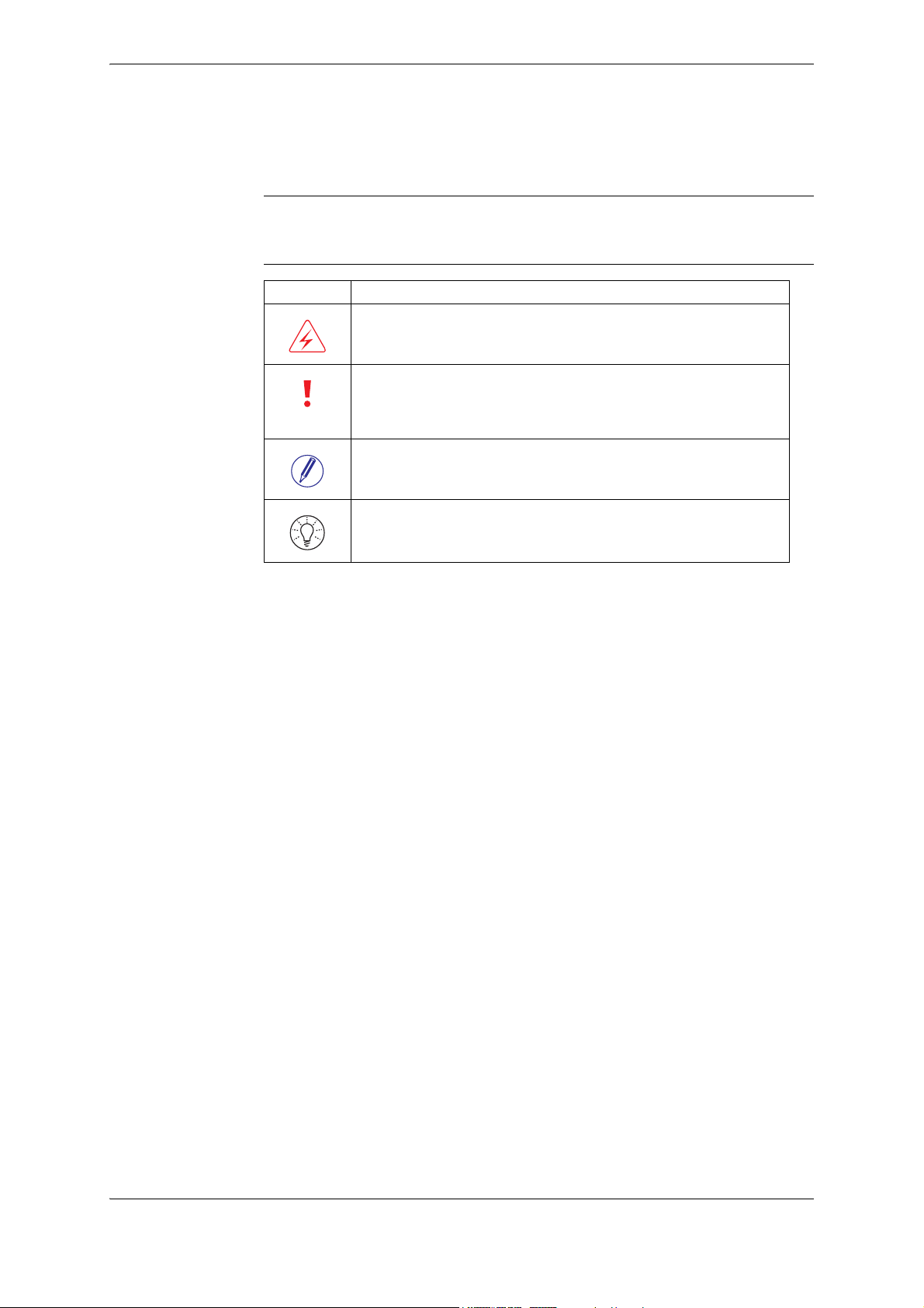
This document contains warning, caution, note and tip icons that point out safety
related conditions and other important or useful information.
Symbol Description
The electrical warning icon indicates the presence of a hazard which
could result in electrical shock.
The caution icon indicates important information or a warning related
to the concept discussed in the text. It might indicate the presence of a
hazard which could result in corruption of software or damage to equipment or property.
The note icon alerts the reader to important facts and conditions.
The tip icon gives the reader useful information related to the concept
discussed in the text.
C13 4 2CMC486004M0201
User Manual Revision: A
Page 9

Chapter 2: Product Overview
Product Overview
Overview
In this chapter
This chapter describes the parts of the meter. It also contains information about
the meter type.
The following topics are covered in this chapter:
2.1 Meter Parts ............................................................................................ 6
2.2 Meter Type ............................................................................................ 7
2CMC486004M0201 5 C13
Revision: A User Manual
Page 10
Product Overview
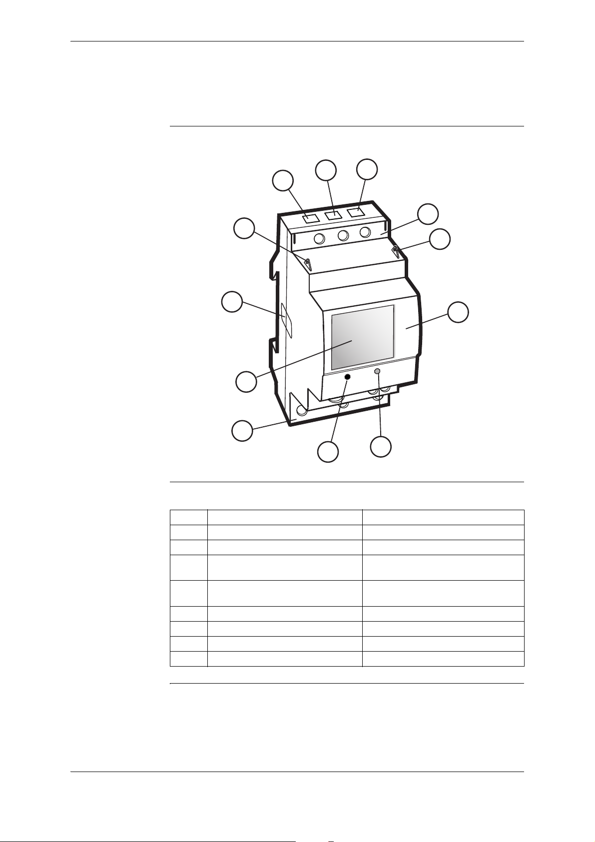
2.1 Meter Parts
Illustration
The parts of the meter are shown in the illustration below:
1
1
1
2
6
5
8
2
7
Parts description
8
4
The following table describes the parts of the meter:
Item Description Comments
1 Terminal for output connections
2 Sealing points
3 Push button For programming and reading metering
4 LED Flashes in proportion to the energy
5 Display LCD for meter reading
6 Sealing label
7 Product data
8 Terminal block
3
data
measured
C13 6 2CMC486004M0201
User Manual Revision: A
Page 11
2.2 Meter Type
Product Overview
C13 meter
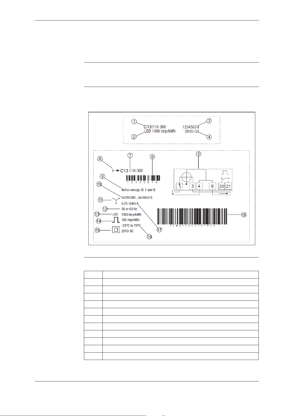
Product label
The C13 is a compact meter for 3-phase metering. The meter is direct connected
for currents up to max. 40 A.
The meter type information that is reflected on the product label is shown in the
example picture below:
Label information
2CMC486004M0201 7 C13
Revision: A User Manual
The information on the type label is explained in the table below:
Item Description
1 Type designation
2 LED pulse frequency
3 Serial number
4 Manufacturing date (year and week)
5 Wiring diagram
6 Bar code with serial number
7 Type designation
8 Energy import
9 Accuracy (active energy)
10 Nominal voltage
11 3-element metering
Page 12

Product Overview
Item Description
12 Frequency
13 LED pulse frequency
14 Pulse frequency
15 Protection class II
16 Operating temperature range
17 Rated current
18 ABB ID
C13 8 2CMC486004M0201
User Manual Revision: A
Page 13

Chapter 3: Installation
Installation
Overview
This chapter describes how to mount the C13 meter and how to connect it to an
electricity network.
In this chapter 3.1 Mounting the Meter .............................................................................. 10
3.2 Environmental Considerations ............................................................. 11
3.3 Installing the Meter .............................................................................. 12
3.3.1 Wiring Diagrams ........................................................................ 13
2CMC486004M0201 9 C13
Revision: A User Manual
Page 14
Installation
3.1 Mounting the Meter
General
DIN-rail mounted
Wall mounted
Standard DIN-rail
This section describes different ways to mount the C13 meter. For some methods
of mounting, additional accessories are needed. For further information about accessories, refer to Main Catalog (2CMC481003C0201).
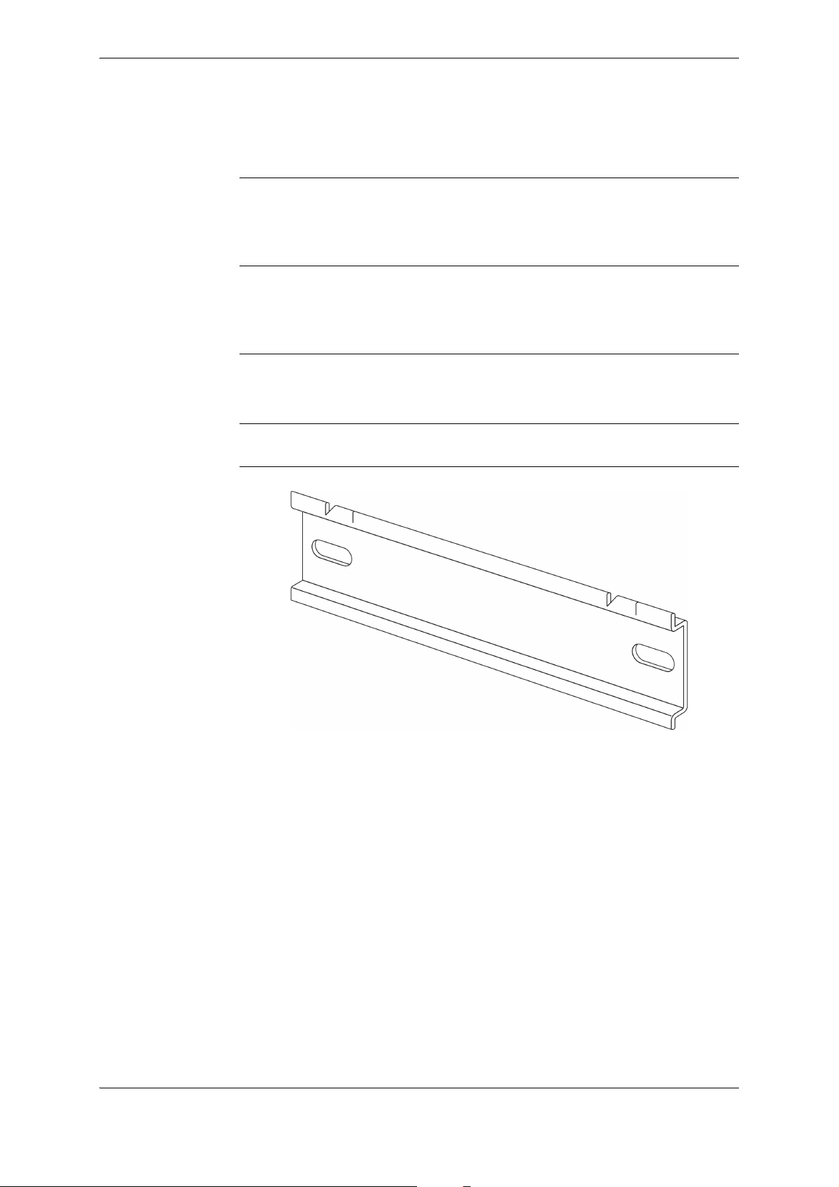
The C13 meters are intended to be mounted on a standard (DIN 50022) DIN-rail.
If this method of mounting is used no extra accessories are needed and the meter
is fastened on the rail by snapping the DIN-rail lock onto the rail.
The recommended way to mount the meter on a wall is to mount a separate DINrail on the wall and then mount the meter on the rail.
The following picture shows a standard DIN-rail.
C13 10 2CMC486004M0201
User Manual Revision: A
Page 15

3.2 Environmental Considerations
Ingress protection
To comply with the protection requirements the product must be mounted in protection class IP 51 enclosures, or better, according to IEC60259.
Mechanical environment
In accordance with the Measuring Directive (2014/32/EU), the product complies
with M1, which means that it can be operated in “...locations with vibration and
shocks of low significance, e.g. for instruments fastened to light suporting structures subject to negligible vibrations and shocks transmitted from local blasting
or pile-driving activities, slamming doors, etc.”
Electromagnetic environment
Installation
Climatic environment
In accordance with the Measuring Directive (2014/32/EU), the product complies
with E2, which means that it can be operated “...in locations with electro magnetic
disturbances corresponding to those likely to be found in other industrial buildings.”
In order to work properly the product should not be operated outside the specified
temperature range of -25°C – +70°C.
In order to work properly the product should not exposed to humidity exceeding
the specified 75% yearly average, 95% on 30 days/year.
2CMC486004M0201 11 C13
Revision: A User Manual
Page 16

Installation
3.3 Installing the Meter
Warning – Electrical equipment should only be installed, accessed, serviced and
E
E
E
maintained by qualified electrical personnel.
Working with high voltage is potentially lethal. Persons subjected to high voltage may
suffer cardiac arrest, burn injuries, or other severe injuries. To avoid such injuries,
make sure to disconnect the power supply before you start the installation.
Warning – For safety reasons it is recommended that the equipment is installed in a
way that makes it impossible to reach or touch the terminal blocks by accident.
The best way to make a safe installation is to install the unit in an enclosure. Further,
access to the equipment should be limited through use of lock and key, controlled by
qualified electrical personnel.
Warning – The meters must always be protected by fuses on the incoming side.
In order to allow for maintenance of transformer rated meters, it is recommended that
there should be a short circuiting device installed near the meter.
Installation
requirements
Install the meter
To comply with the protection requirements the meter must be mounted in protection class IP 51 enclosures, or better, according to IEC 60259.
Meters with wireless communication should not be installed closer than 20 cm
from people.
Follow the steps in the table below to install the meter:
Step Action
1 Switch off the mains power.
2 Place the meter on the DIN-rail and make sure it snaps onto it.
3 Strip the cable insulation to the length that is indicated on the meter.
4 Connect the cables according to the wiring diagram that is printed on the me-
ter and tighten the screws (0.8 Nm).
5 Install the circuit protection (max 40 A).
6 Connect the output to an external power supply (max 5–40 V). See the wiring
diagram printed on the meter.
7 Turn on the mains power.
Verify the
installation
C13 12 2CMC486004M0201
User Manual Revision: A
The C13 meter has a red LED next to the push button on the front of the meter
that flashes proportionally to the active energy. The LED has a fixed pulse frequency of 1000 imp/kWh and can be used to test and verify the installation. If the
LED flashes when the mains power is turned on, the installation was successful.
Page 17

3.3.1 Wiring Diagrams
9
1
34
6
7
12
10
Installation
4-wire connection
3.3.1.1 Outputs
Fixed, 1 output
The following diagram shows a 4-wire connection of a direct connected 3-phase
meter:
2CMC486004M0201 13 C13
Revision: A User Manual
Page 18

Installation
C13 14 2CMC486004M0201
User Manual Revision: A
Page 19

Chapter 4: User Interface
User Interface
Overview
In this chapter
This chapter gives an overview of the display and of the functions of the button
on the meter.
The following topics are covered in this chapter:
4.1 Display and buttons ............................................................................. 16
4.2 Menu Structure .................................................................................... 17
2CMC486004M0201 15 C13
Revision: A User Manual
Page 20

User Interface
123
k Arh
!
4.1 Display and buttons
Display
The display consists of icons, digits and letters. The measured value/menu options
are displayed with large letters. The measured unit is displayed on the bottomright side of the display, and the status icons are displayed at the upper part of the
display, see figure below.
Status Icons
Button
The status icons are shown in the table below.
Icon Indication Comment
Active error When a error has been detected,
the icon will be lit on the display.
When no error has been detected,
the icon will be turned off.
Metering in progress. When a load is connected to the
meter, the icon will flash to indicate
metering. When no load is connected, the icon will be turned off.
The meter has one push button which is located below the display. A short press
on the button (less than 1 sec) will step through the menu/submenu. A long press
(more than 1 sec) followed by a release of the button will open the set menu or
select an item in the menu.
C13 16 2CMC486004M0201
User Manual Revision: A
Page 21

4.2 Menu Structure
–
–
–
–
–
Active energy
Active energy
max resolution
Active power,
Output
Exit
Exit
Alarm power
Alarm power factor
Alarm level
on
Alarm on
delay
Alarm level
off
Save
Alarm off
delay
View menu
Set menu
Select function Set alarm
–
Active power, L1
–
Active power, L2
–
Active power, L3
Alarm voltage, L1
Alarm voltage, L2
Alarm voltage, L3
Alarm current, L1
Alarm current, L2
Alarm current, L3
total
–
Voltage, L1
–
Voltage, L2
–
–
–
Current, L1
Power factor
Error
–
Voltage, L3
–
Current, L2
–
Current, L2
–
Output state
–
Version
–
CrC
Pulse output
Out on
Out o
Exit
User Interface
Overview
Menu structure
This section will give an introduction to the menu structure.
The menu structure of the meter can be viewed in the following figure
Navigation
View menu
2CMC486004M0201 17 C13
Revision: A User Manual
To navigate in the menu, use the short press to navigate between the different
menu items, and the long press to select a menu item. When performing settings,
the short press is used to change the value of a specific setting, and the long press
is used to toggle between different digits.
In the view menu, the following choices can be made.
Choice in menu Output on
Active energy <numerical
display
value>
kWh
No. of
digits
7 0 kWh 0 9999999
No. of
decimals
Unit Min.
value
Max. value
Page 22

User Interface
Choice in menu Output on
display
Active energy max
resolution
Active power Total <numerical
Active power
Phase 1
Active power
Phase 2
Active power
Phase 3
Voltage Phase 1 <numerical
Voltage Phase 2 <numerical
Voltage Phase 3 <numerical
Current Phase 1 <numerical
Current Phase 2 <numerical
Current Phase 3 <numerical
Power factor <numerical
Output state
- Alarm on, or N/A N/A N/A N/A N/A
- Alarm off, or N/A N/A N/A N/A N/A
- Output on, or N/A N/A N/A N/A N/A
- Output off, or N/A N/A N/A N/A N/A
- Pulse out N/A N/A N/A N/A N/A
Firmware version
Part 1
Firmware version
Part 2
Firmware version
Part 3
<numerical
value>
Wh
value>
W
<numerical
value>
W
<numerical
value>
W
<numerical
value>
W
value>
V
value>
V
value>
V
value>
A
value>
A
value>
A
value>
N/A 3 N/A N/A 1 255
N/A 3 N/A N/A 0 255
N/A 3 N/A N/A 0 255
No. of
digits
6 3 Wh 0 999.999
5 0 W 0 99999
5 0 W 0 99999
5 0 W 0 99999
5 0 W 0 99999
30 V0999
30 V0999
30 V0999
31 A099.9
31 A099.9
31 A099.9
43 N/A01
No. of
decimals
Unit Min.
value
Max. value
C13 18 2CMC486004M0201
User Manual Revision: A
Page 23

User Interface
Set menu
Set alarm menu
Choice in menu Output on
display
CRC Part 1 N/A 4 N/A N/A 0000 FFFF
CRC Part 2 N/A 4 N/A N/A 0000 FFFF
Error Er <numerical
value>
No. of
digits
4 N/A N/A N/A N/A
No. of
decimals
Unit Min.
value
Max. value
The set menu is used to set different options in the meter. The set menu is reached
by using the long press when located in the view menu. The following choices are
available in the set menu, see table below.
Choice in menu Output on display
Output
Exit
When choosing Exit, the menu will return to the view menu. When choosing Output, the following choices will be available.
Choice in menu Output on display Explanation
Alarm power
VV
Alarm voltage
V
Alarm voltage
V
Alarm voltage
V
Alarm current
A
Alarm current
A
Alarm current
A
By choosing this option, the
alarm will be set with regards to
the measured power.
By choosing this option, the
alarm will be set with regards to
the measured voltage on
Phase 1.
By choosing this option, the
alarm will be set with regards to
the measured voltage on
Phase 2.
By choosing this option, the
alarm will be set with regards to
the measured voltage on
Phase 3.
By choosing this option, the
alarm will be set with regards to
the measured current on Phase
1.
By choosing this option, the
alarm will be set with regards to
the measured current on Phase
2.
By choosing this option, the
alarm will be set with regards to
the measured current on Phase
3.
2CMC486004M0201 19 C13
Revision: A User Manual
Page 24

User Interface
Choice in menu Output on display Explanation
Alarm power factor By choosing this option, the
alarm will be set regarding to
the measured power factor.
Pulse output By choosing this option, the
pulse output function will be activated.
Out on By choosing this option, the
output will be set to static on.
Out off By choosing this option, the
output will be set to static off.
Exit Go back to the set menu.
When either Alarm power, Alarm voltage, Alarm current or Alarm factor has
been chosen, the following choices will be available.
Choice Output on display Unit Explanation
Alarm level on W/V/A/- When the measured value
passes the set value, the
alarm will be triggered.
Alarm on delay seconds When the measured value
passes the set value and
remains for the set time,
the alarm will be triggered.
Alarm level off W/V/A/- When the measured value
passes the set value, the
alarm will be cleared.
Alarm off delay seconds
Save N/A This option saves the
Exit N/A Go back to the set menu
When the measured value
passes the set value and
remains for the set time,
the alarm will be cleared.
alarm settings.
without saving. Use this
option to view the current
alarm settings.
C13 20 2CMC486004M0201
User Manual Revision: A
Page 25

Chapter 5: Meter Settings
Meter Settings
Overview
In this chapter
This chapter describes how to configure the functions of the meter, including
alarm settings.
The following topics are covered in this chapter:
5.1 Setting the Output ................................................................................ 22
5.2 Setting the Alarm ................................................................................. 24
2CMC486004M0201 21 C13
Revision: A User Manual
Page 26

Meter Settings
5.1 Setting the Output
About the output
Output state
The C13 meter has one output which can be used for three different purposes.
When one of the three options has been chosen for the output, the remaining two
options are automatically disabled.
• Alarm monitoring
The output is used for monitoring if an alarm has been triggered or not.
• Static level
The output is set as static, either as static on or static off.
• Pulse output
The output is set as a pulse output.
The Output state in the main menu indicates what function is activated. See table
below for the different functions that can be activated
Activated function Output on display Comment
Alarm on The alarm is set and has been trig-
gered.The pulse output exit is deactivated.
Alarm off The alarm is set but has not been trig-
gered. The pulse output exit is deactivated.
Output on There is always a continous signal on the
output.
Output off The output is closed for all traffic, both in-
bound and outbound.
Pulse out The output is activated with a frequency
based on measured energy. The alarm
function is deactivated.
Set output to
pulse output
C13 22 2CMC486004M0201
User Manual Revision: A
To set the pulse output to be available for pulse measuring, perform the following
steps when located in the view menu.
Step Action Comment
1 When located in the view menu, use the long
press to get to the set menu.
2 Use the long press to get to the selection of func-
tions menu.
3 Toggle through the menu to get to the Pulse out
choice. Use the long press to choose Pulse out
( on the display).
-
-
The Pulse out choice in the
selection of function menu
is displayed as:
Page 27

Meter Settings
Disable output
Activate output
The output can also be disabled by performing the following steps when located
in the view menu.
Step Action Comment
1 When located in the view menu, use the long
press to get to the set menu
2 Use the long press to get to the selection of func-
tion menu.
3 Toggle through the menu to get to the Output off
choice ( on the display). Use the long
press to choose the Output off.
-
-
The Output off choice in
the view menu is displayed as:
To activate the output, perform the following steps when located in the view
menu.
Step Action Comment
1 When located in the view menu, use the long
press to get to the set menu.
2 Use the long press to get to the selection of func-
tion menu.
3 Toggle through the menu to get to the Output on
choice ( on the display). Use the long
press to choose the Output on.
-
-
The Output on choice in
the view menu is displayed
as:
2CMC486004M0201 23 C13
Revision: A User Manual
Page 28

Meter Settings
5.2 Setting the Alarm
About the alarm
The alarm function gives the user the possibility to set an alarm that will trigger
when a defined limit is reached by the measured value. See table for more information.
Choice in menu Unit Output on display Range
Alarm power W
W
Alarm voltage Phase 1 V
V
Alarm voltage Phase 2 V
V
Alarm voltage Phase 3 V
V
Alarm current Phase 1 A
A
Alarm current Phase 2 A
A
Alarm current Phase 3 A
A
Alarm power factor - 0–0.999
0–99999 W
0–299 V
0–299 V
0–299 V
0–40.00 A
0–40.00 A
0–40.00 A
If the value is set above the max range, the meter will automatically set the value
to the max value allowed by the range.
Set alarm
Example: Alarm current is set to 100.0 A by the user, but the max value is 40.0
A, so the meter will use the max value, in this case 40.0 A.
If an alarm has been set, the output state will indicate if the alarm is triggered (AL
On) or not (AL OFF). The magnitude of the set alarm is also displayed in the
output state.
To set an alarm, perform the following steps when located in the view menu.
Step Action Comment
1 Use the long press to get to the set menu -
2 Use the long press to get to the selection of
function menu
3 Toggle through the menu to choose what mag-
nitude to set. Choose one of the following:
Alarm power (W), Alarm voltage (V), Alarm
current (A) and Alarm factor (no magnitude).
4 Set the alarm value that the measured value
must pass in order for the alarm to trigger
(Alarm level on).
-
Use the long press to choose.
Use the short press to change
the value of the digit, and the
long press to step through the
different digits.
C13 24 2CMC486004M0201
User Manual Revision: A
Page 29

Step Action Comment
5 Set the time frame that the measured value
must pass the set alarm value in order for the
alarm to trigger (Alarm on delay).
6 Set the alarm value that the measured value
must pass in order for the alarm to be cleared
(Alarm level off).
7 Set the time frame that the measured value
must pass the set alarm value in order for the
alarm to be cleared (Alarm off delay).
8 To save the alarm settings and enable the
alarm function, use the long press when located in the save-menu ( on the display).
After performing this setting, the alarm is set.
Use the short press to change
the value of the digit, and the
long press to step through the
different digits.
Use the short press to change
the value of the digit, and the
long press to step through the
different digits.
Use the short press to change
the value of the digit, and the
long press to step through the
different digits.
If not choosing the option
save, the settings will not be
saved and the previously
saved setting will be used instead. The alarm will not be activated.
Meter Settings
Read alarm
The Output option in the View menu shows whether a programmed alarm has
been triggered or not. A triggered alarm displays as AL On, and an alarm that has
not been triggered displays as AL OFF.
2CMC486004M0201 25 C13
Revision: A User Manual
Page 30

Meter Settings
C13 26 2CMC486004M0201
User Manual Revision: A
Page 31

Chapter 6: Technical Description
Technical Description
Overview
In this chapter
This chapter describes the technical functions of the C13 meter.
The following topics are covered in this chapter:
6.1 Energy Values ..................................................................................... 28
6.2 Instrumentation .................................................................................... 29
6.3 Outputs ................................................................................................ 30
6.4 Alarm ................................................................................................... 31
2CMC486004M0201 27 C13
Revision: A User Manual
Page 32

Technical Description
6.1 Energy Values
General
Presentation of
register values
The energy values are stored in energy registers. The different energy registers
can be divided into:
• Registers containing active energy.
The energy values can be read directly on the display by using the button on the
meter.
In direct connected meters the energy is usually displayed with a fixed unit and
number of decimals (normally kWh, with no decimals).
In case the energy is displayed with fixed units and number of decimals the energy
will “roll over” to zeros when the energy is increment ed if all nines are displayed.
The meter can however contain more digits internally, which can be read out via
communication if the meter is equipped with a communication interface.
C13 28 2CMC486004M0201
User Manual Revision: A
Page 33

6.2 Instrumentation
Technical Description
Instrumentation
functions
Accuracy
The following table shows the complete instrumentation functions of the C13 meter.
Instrumentation C13
Active power L1 X
Active power L2 X
Active power L3 X
Voltage L1 - N X
Voltage L2 - N X
Voltage L3 - N X
Current L1 X
Current L2 X
Current L3 X
Power factor, Total X
All instrumentation data accuracy is defined within the voltage range -20% –
+15% of the stated nominal voltage and within the current range 5% of the base
current to the maximum current.
2CMC486004M0201 29 C13
Revision: A User Manual
Page 34

Technical Description
6.3 Outputs
About outputs
The C13 meter has one output which can be used for three different purposes.
When one of the three options has been choosen for the output, the remaining two
options are automatically disabled.
• Alarm monitoring
The output is used for monitoring if an alarm has been triggered or not.
• Static level
The output is set as static, either as static on or static off.
• Pulse output
The output is set as a pulse output.
On the pulse output the meter sends out a specified number of pulses (pulse frequency) per kilowatt hour (kilovar for reactive pulse outputs). The amount of
pulses sent out are in proportion to the energy flowed through the meter.
The meter has a pulse output frequency of 1000 imp/kWh and the pulse width is
100 ms.
C13 30 2CMC486004M0201
User Manual Revision: A
Page 35

6.4 Alarm
Technical Description
General
Quantities
Functional
description
The purpose of the alarm function is to enable monitoring of quantities in the
meter. Monitoring can be set to high or low level detection. High level detection
gives an alarm when the level of a quantity goes above the set level. Low level
detection gives an alarm when the value goes below the set level.
Depending on the meter type all or a subset of the following quantities can be
monitored:
• Active power
• Power factor
• Current L
• Voltage L-N
When the value of the monitored quantity passes the activation level, and remains
there for a period of time equal or longer than the specified time delay, the alarm
is activated. In the same way, the alarm is deactivated when the value passes the
deactivation level and remains there for a time equal to or longer than the specified time delay.
If the activation level is higher than the deactivation level, the alarm is activated
when the value of the monitored quantity is higher than the activation level.
If the activation level is lower than the deactivation level, the alarm is activated
when the vale of the monitored quantity is lower than the activation level.
2CMC486004M0201 31 C13
Revision: A User Manual
Page 36

Technical Description
C13 32 2CMC486004M0201
User Manual Revision: A
Page 37

Chapter 7: Technical data
Technical data
Overview
In this chapter
This chapter contains the technical specifications and the physical dimensions of
the meter.
The following topics are covered in this chapter:
7.1 Technical Specifications ...................................................................... 34
7.2 Physical Dimensions ........................................................................... 36
2CMC486004M0201 33 C13
Revision: A User Manual
Page 38

Technical data
7.1 Technical Specifications
Specifications for C13 direct connected meter
Voltage/current inputs
Nominal voltage 3x230/400 VAC
Voltage range 3x220–240 VAC (-20% – +15%)
Power dissipation voltage circuits 1.5 VA (0.6 W) total
Power dissipation current circuits 0.04 VA (0.04 W) per phase at 230 VAC and I
Base current I
Reference current I
Transitional current I
Maximum current I
Minimum current I
Starting current I
Terminal wire area 0.5–10 mm
Recommended tightening torque 0.8 Nm
General data
Frequency 50 or 60 Hz ± 5%
Accuracy 1% (Cl. 1, Cl. B)
Display of energy 7-digit LCD
Mechanical
Material Polycarbonate in transparent front glass. Glass reinforced
Weight 190 g
Environmental
Operating temperature -25°C – +70°C
Storage temperature -25°C – +85°C
Humidity 75% yearly average, 95% on 30 days/year.
Resistance to fire and heat Terminal 960°C, cover 650°C (IEC 60695-2-1)
Pulse output
Current 2–100 mA
Voltage 5–40 VDC
Pulse output frequency 1000 imp/kWh
Pulse length 100 ms
Terminal wire area 0.5–6 mm
Recommended tightening torque 0.8 Nm
Pulse indicator(LED)
Pulse frequency 1000 imp/kWh
Pulse length 40 ms
EMC compatibility
5 A
b
5 A
ref
0.5 A
tr
40 A
max
0.25 A
min
< 20 mA
st
polycarbonate in bottom case and upper case. Polycarbonate
in terminal cover.
b
2
2
C13 34 2CMC486004M0201
User Manual Revision: A
Page 39

Technical data
Impulse voltage test 6 kV 1.2/50µs (IEC 60060-1)
Surge voltage test 4 kV 1.2/50µs (IEC 61000-4-5)
Fast transient burst test 4 kV (IEC 61000-4-4)
Immunity to electromagnetic HF-fields 80 MHz – 2 GHz at 10 V/m (IEC61000-4-3)
Immunity to conducted disturbance 150kHz – 80MHz (IEC 61000-4-6)
Immunity to electromagnetic disturbances
Radio frequency emission EN 55022, class B (CISPR22)
Electrostatic discharge 15 kV (IEC 61000-4-2)
Standards IEC 62052-11, IEC 62053-21 class 1, GB/T 17215.211-2006,
2–150 kHz for kWh-meters
GB/T 17215.321-2008 class 1 & 2, GB 4208-2008, EN 504701, EN 50470-3 category B
2CMC486004M0201 35 C13
Revision: A User Manual
Page 40

Technical data
7.2 Physical Dimensions
C13
The following drawing shows the physical dimensions of the C13 meter
C13 36 2CMC486004M0201
User Manual Revision: A
Page 41

Chapter 8: Troubleshooting
Troubleshooting
Overview
In this chapter
This chapter describes the error codes and the warnings that can be received from
the meter.
The following topics are covered in this chapter:
8.1 Error Codes and Warnings .................................................................. 38
2CMC486004M0201 37 C13
Revision: A User Manual
Page 42

Troubleshooting
8.1 Error Codes and Warnings
Error codes
Warnings
Error code Description
Er0041 Program CRC error
Er0042 Persistent storage CRC error
Er0051 Vref is not vdd/2
Er0052 Temperature sensor error
Warning Description
Er1007 Negative power
Er1008 Frequency outside meter specification
C13 38 2CMC486004M0201
User Manual Revision: A
Page 43

Chapter 9: Service & Maintenance
Service & Maintenance
Overview
In this chapter
This chapter contains information about service and maintenance of the product.
The following topics are covered in this chapter:
9.1 Service and Maintenance .................................................................... 40
2CMC486004M0201 39 C13
Revision: A User Manual
Page 44

Service & Maintenance
9.1 Service and Maintenance
Service
Cleaning
This product contains no parts that can be repaired or exchanged. A broken meter
must be replaced.
If the meter needs to be cleaned, use a lightly moistened cloth with a mild detergent to wipe it.
Caution – Be careful that no liquid gets into the meter since it can ruin the equipment.
C
C13 40 2CMC486004M0201
User Manual Revision: A
 Loading...