

Page 1
Product manual │ 02.11.2020
ABB i-bus® KNX
Busch-SmartTouch
Busch-SmartTouch
6136/07-xxx-500
®
®
7''
Page 2

│
Inhaltsverzeichnis
Inhaltsverzeichnis
1 Notes on the instruction manual .................................................................................................................. 13
2 Safety ........................................................................................................................................................... 14
2.1 Information and symbols used ......................................................................................................... 14
2.2 Intended use .................................................................................................................................... 15
2.3 Improper use .................................................................................................................................... 15
2.4 Target group / Qualifications of personnel ....................................................................................... 16
2.5 Safety instructions ............................................................................................................................ 16
3 Information on protection of the environment ............................................................................................. 17
3.1 Environment ..................................................................................................................................... 17
4 Product description ...................................................................................................................................... 18
4.1 Scope of supply ................................................................................................................................ 19
4.2 Additional necessary components ................................................................................................... 19
4.3 Overview of types ............................................................................................................................. 19
4.4 Overview of KNX functions .............................................................................................................. 19
4.5 Additional function of hearing loop ................................................................................................... 20
4.6 Device overview ............................................................................................................................... 20
5 Technical data ............................................................................................................................................. 21
6 Circuit diagrams and dimensional drawings................................................................................................ 22
6.1 Dimensional drawings ...................................................................................................................... 22
6.2 Circuit diagrams ............................................................................................................................... 23
7 Connection, installation / mounting ............................................................................................................. 24
7.1 Planning instructions ........................................................................................................................ 24
7.2 Safety instructions ............................................................................................................................ 24
7.3 Preparatory steps ............................................................................................................................. 25
7.4 Mounting ........................................................................................................................................... 25
7.4.1
Overview of mounting versions .................................................................................................. 26
7.4.2
Mounting in flush-mounted installation box in hollow wall ........................................................... 26
7.4.3
Mounting in flush-mounted installation box in solid wall ............................................................. 27
7.4.4
Mounting with surface-mounted mounting frame ........................................................................ 28
7.4.5
Standard flush-mounted box ...................................................................................................... 30
7.4.6
Old control panel box 6136/UP-500 (MD/U 1.1) ......................................................................... 30
7.4.7
Table stand 83506-500 .............................................................................................................. 30
7.4.8
Connection and installation ........................................................................................................ 31
7.5 Dismantling ....................................................................................................................................... 32
8 Initial commissioning ................................................................................................................................... 33
9 Commissioning via DCA (from ETS5) ......................................................................................................... 35
9.1 Integration into the KNX system (ETS) ............................................................................................ 35
9.1.1
Installation of the Busch-SmartTouch® ETS app ........................................................................ 35
9.1.2
Installation sequence .................................................................................................................. 36
9.1.3
Product manual 2CKA001473B9264
Integrating the Busch-SmartTouch® 7'' into the ETS .................................................................. 36
2
Page 3

│
9.1.4
Further KNX settings in the Busch-SmartTouch® 7'' ................................................................... 36
9.2 Overview of the DCA commissioning tool ....................................................................................... 37
9.2.1
Starting the DCA ........................................................................................................................ 37
9.3 Screen areas of the DCA ................................................................................................................. 38
9.4 Explanation of the basic structure (Terms) ...................................................................................... 40
9.5 Commissioning sequence ................................................................................................................ 42
9.6 Configuring basic settings for the panel .......................................................................................... 42
9.6.1
Basic settings (system settings) of the panel .............................................................................. 43
9.7 Creation of the navigation struc ture ................................................................................................. 56
9.7.1
Creating operating pages (start pages) ...................................................................................... 56
9.7.2
Creating operating pages for rooms ........................................................................................... 57
9.7.3
Creating operating pages for floors ............................................................................................ 58
9.7.4
Editing operating pages .............................................................................................................. 59
9.7.5
Editing floors and rooms ............................................................................................................. 61
9.8 Configuration of the operating pages............................................................................................... 63
9.8.1
"Switch" control element ............................................................................................................. 65
9.8.2
Control element "Rocker switch" ................................................................................................ 65
9.8.3
"Dimmer" control element ........................................................................................................... 65
9.8.4
Control element: "Dimmer slider" ............................................................................................... 65
9.8.5
Operation of "RGBW" control element“ ...................................................................................... 65
9.8.6
Control element: "Value slider" ................................................................................................... 66
9.8.7
"Blind" control element ............................................................................................................... 66
9.8.8
Control element "Fan switch" ..................................................................................................... 66
9.8.9
"Scene" control element ............................................................................................................. 66
9.8.10 "Display" control element ........................................................................................................... 66
9.8.11 Control element "RTC control element" ...................................................................................... 66
9.8.12 "Page link" control element ......................................................................................................... 67
9.8.13 Control element "Audio control" .................................................................................................. 67
9.9 Editing control elements ................................................................................................................... 67
9.9.1
Delete control element ............................................................................................................... 67
9.9.2
Copy control element ................................................................................................................. 68
9.9.3
Add control element to favourites list .......................................................................................... 68
9.10 Configuration of applications and application pages ....................................................................... 69
9.10.1 Application "Door communication" ............................................................................................. 69
9.10.2 Application "Fault and alarm messages" .................................................................................... 70
9.10.3 Application "Scene actuator" ...................................................................................................... 71
9.10.4 Application "Presence simulation" .............................................................................................. 71
9.10.5 Application "Time programs" ...................................................................................................... 72
9.10.6 Application "Logical functions" .................................................................................................... 72
9.10.7 Application "Internal RTC" .......................................................................................................... 73
9.10.8 "Favourite control elements" ....................................................................................................... 73
9.11 Editing communication objects ........................................................................................................ 74
9.12 Editing group addresses .................................................................................................................. 75
9.13 Additional tools (functions) ............................................................................................................... 76
9.13.1 Import ......................................................................................................................................... 76
9.13.2 Export ......................................................................................................................................... 77
9.13.3 Preview ...................................................................................................................................... 77
9.13.4 Reset layout ............................................................................................................................... 77
Inhaltsverzeichnis
Product manual 2CKA001473B9264
3
Page 4

│
Inhaltsverzeichnis
10 Commissioning via Power-Tool (from ETS3) .............................................................................................. 78
10.1 Integration into the KNX system (ETS) ............................................................................................ 78
10.1.1 Installation of the plug-in Power-Tool for the Busch-SmartTouch® ............................................. 78
10.1.2 Installation sequence .................................................................................................................. 78
10.1.3 Integrating the Busch-SmartTouch® 7'' into the ETS .................................................................. 79
10.1.4 Further KNX settings in the Busch-SmartTouch® 7'' ................................................................... 79
10.2 Overview of the Power-Tool commissioning tool ............................................................................ 80
10.2.1 Starting the Power-Tool .............................................................................................................. 80
10.3 Power-Tool screen areas ................................................................................................................. 81
10.4 Explanation of the basic structure (Terms) ...................................................................................... 83
10.5 Commissioning sequence ................................................................................................................ 84
10.6 Configuring basic settings for the panel .......................................................................................... 84
10.6.1 Basic settings (system settings) of the panel .............................................................................. 85
10.7 Creation of the navigation struc ture ............................................................................................... 101
10.7.1 Creating operating pages (start pages) .....................................................................................101
10.7.2 Creating operating pages for rooms ..........................................................................................101
10.7.3 Creating operating pages for floors ...........................................................................................102
10.7.4 Editing operating pages .............................................................................................................103
10.7.5 Editing floors and rooms ............................................................................................................104
10.8 Configuration of the operating pages............................................................................................. 106
10.8.1 "Switch" control element ............................................................................................................107
10.8.2 Control element "Rocker switch" ...............................................................................................107
10.8.3 "Dimmer" control element ..........................................................................................................108
10.8.4 Control element: "Dimmer slider" ..............................................................................................108
10.8.5 Operation of "RGBW" control element“ .....................................................................................108
10.8.6 Control element: "Value slider" ..................................................................................................109
10.8.7 "Blind" control element ..............................................................................................................109
10.8.8 Control element "Fan switch" ....................................................................................................109
10.8.9 "Scene" control element ............................................................................................................109
10.8.10 "Display" control element ..........................................................................................................109
10.8.11 Control element "RTC control element" .....................................................................................109
10.8.12 "Page link" control element ........................................................................................................110
10.8.13 Control element "Audio control" .................................................................................................110
10.9 Editing control elements ................................................................................................................. 110
10.9.1 Delete control element ..............................................................................................................110
10.9.2 Copy and position control element ............................................................................................111
10.10 Configuration of applications and application pages ..................................................................... 111
10.10.1 Application "Door communication" ............................................................................................111
10.10.2 Application "Fault and alarm messages" ...................................................................................112
10.10.3 Application "Scene actuator" .....................................................................................................113
10.10.4 Application "Presence simulation" .............................................................................................113
10.10.5 Application "Time programs" .....................................................................................................113
10.10.6 Application "Logical functions" ...................................................................................................114
10.10.7 Application "Internal RTC" .........................................................................................................114
10.11 Editing communication objects ...................................................................................................... 115
10.12 Editing group addresses ................................................................................................................ 117
10.13 Additional tools (functions) ............................................................................................................. 118
10.13.1 Programming (exporting) ...........................................................................................................118
10.13.2 Preview .....................................................................................................................................118
Product manual 2CKA001473B9264
4
Page 5

│
Inhaltsverzeichnis
11 Operation ................................................................................................................................................... 119
11.1 General control and display functions ........................................................................................... 119
11.2 Control elements ............................................................................................................................ 121
11.2.1 Basic structures of control elements ..........................................................................................122
11.2.2 Additional basic principles .........................................................................................................123
11.2.3 Adjustable control elements ......................................................................................................124
11.3 Special functions ............................................................................................................................ 131
11.3.1 Editing .......................................................................................................................................131
11.3.2 Call-up and editing of the favourites list .....................................................................................132
11.3.3 Access to pages ........................................................................................................................134
11.3.4 Return to the previous page ......................................................................................................134
11.4 Operating actions of the "Door communication" application ......................................................... 135
11.4.1 Establishing a speech and video connection .............................................................................136
11.4.2 Opening the door ......................................................................................................................136
11.4.3 Activating mute (mite timer) .......................................................................................................137
11.4.4 Switching light ...........................................................................................................................137
11.4.5 Events and image storage / history ...........................................................................................138
11.5 Control actions of additional applications ...................................................................................... 139
11.5.1 Presence simulation ..................................................................................................................139
11.5.2 Fault and alarm messages ........................................................................................................141
11.5.3 Time programs ..........................................................................................................................144
11.6 Inserting the micro SD card (SDHC) .............................................................................................. 148
11.7 System settings .............................................................................................................................. 148
11.7.1 Settings for "Door communication" application ..........................................................................151
11.8 Setting the device for door communication ................................................................................... 153
11.8.1 Terminal resistor .......................................................................................................................153
11.8.2 Setting master/slave switches ...................................................................................................153
12 Addressing ................................................................................................................................................. 154
12.1 Addressing the stations .................................................................................................................. 154
12.1.1 Trimmer .....................................................................................................................................154
12.1.2 Setting the address of the outdoor station .................................................................................155
12.1.3 Assigning the doorbell push-button of an outdoor station to an apartment ................................155
12.1.4 Setting the address of the indoor station ...................................................................................155
12.1.5 Setting of the "Standard outdoor station" ...................................................................................156
13 Update ....................................................................................................................................................... 160
13.1 Firmware update ............................................................................................................................ 160
13.2 Transfer of PID file (Configuration file) .......................................................................................... 161
14 Maintenance .............................................................................................................................................. 162
14.1 Cleaning ......................................................................................................................................... 162
15 Control elements and application parameter ............................................................................................ 163
15.1 "Switch" control element ................................................................................................................ 163
15.1.1 Name of the control element .....................................................................................................163
15.1.2 Function of the control element .................................................................................................163
15.1.3 Size of the button ......................................................................................................................163
15.1.4 Type of switch ...........................................................................................................................163
Product manual 2CKA001473B9264
5
Page 6

│
15.1.5 Object type 1 / value 2 ...............................................................................................................164
15.1.6 Status control element (icon/text) is operated via a separate object ..........................................167
15.1.7 Icon type....................................................................................................................................168
15.1.8 Enable 1-bit communication object "Disable" ............................................................................169
15.2 Control element "Rocker switch" ................................................................................................... 170
15.2.1 Name of the control element .....................................................................................................170
15.2.2 Function of the control element .................................................................................................170
15.2.3 Size of the button ......................................................................................................................170
15.2.4 Icon type....................................................................................................................................170
15.2.5 Status control element (icon/text) is operated via a separate object ..........................................171
15.2.6 Object type ................................................................................................................................171
15.2.7 Enable 1-bit communication object "Disable" ............................................................................175
15.3 "Dimmer" control element .............................................................................................................. 176
15.3.1 Name of the control element .....................................................................................................176
15.3.2 Function of the control element .................................................................................................176
15.3.3 Size of the button ......................................................................................................................176
15.3.4 Icon type....................................................................................................................................176
15.3.5 Icon for On / icon for Off ............................................................................................................176
15.3.6 Position for dim up icon .............................................................................................................177
15.3.7 Icon for dimming up / icon for dimming down ............................................................................177
15.3.8 Status control element (icon) is operated via a separate object ................................................177
15.3.9 Status of dimming value is controlled by a separate object .......................................................177
15.3.10 Manner of dimming ....................................................................................................................178
15.3.11 Enable 1-bit communication object "Disable" ............................................................................179
15.4 Control element: "Dimmer slider" ................................................................................................... 180
15.4.1 Name of the control element .....................................................................................................180
15.4.2 Function of the control element .................................................................................................180
15.4.3 Size of the button ......................................................................................................................180
15.4.4 Icon type....................................................................................................................................180
15.4.5 Icon for On / icon for Off ............................................................................................................180
15.4.6 Slider from .................................................................................................................................181
15.4.7 Status control element (icon) is operated via a separate object ................................................181
15.4.8 Display value in control element ................................................................................................182
15.4.9 Slider sends ..............................................................................................................................183
15.4.10 Brightness change [%] ..............................................................................................................183
15.4.11 Enable 1-bit communication object "Disable" ............................................................................183
15.5 Operation of "RGBW" control element“ ......................................................................................... 184
15.5.1 Name of the control element .....................................................................................................184
15.5.2 Function of the control element .................................................................................................184
15.5.3 Display value in control element ................................................................................................184
15.5.4 Type of colour/white lamp .........................................................................................................184
15.5.5 Brightness change [%] ..............................................................................................................186
15.5.6 Telegram is repeated every [sec.]: ............................................................................................187
15.5.7 Enable 1-bit communication object "Disable" ............................................................................187
15.6 Control element: "Value slider" ...................................................................................................... 188
15.6.1 Name of the control element .....................................................................................................188
15.6.2 Function of the control element .................................................................................................188
15.6.3 Size of the button ......................................................................................................................188
15.6.4 Slider from .................................................................................................................................188
15.6.5 Display value in control element ................................................................................................188
15.6.6 Slider sends ..............................................................................................................................189
Product manual 2CKA001473B9264
Inhaltsverzeichnis
6
Page 7

│
15.6.7 Object type ................................................................................................................................190
15.6.8 Enable 1-bit communication object "Disable" ............................................................................191
15.7 "Blind" control element ................................................................................................................... 192
15.7.1 Name of the control element .....................................................................................................192
15.7.2 Function of the control element .................................................................................................192
15.7.3 Size of the button ......................................................................................................................192
15.7.4 Type of control ..........................................................................................................................192
15.7.5 Icon type....................................................................................................................................193
15.7.6 Status control element (icon) is operated via a separate object ................................................194
15.7.7 Enable 1-bit communication object "Disable" ............................................................................195
15.8 Control element "Fan switch" ......................................................................................................... 196
15.8.1 Name of the control element .....................................................................................................196
15.8.2 Function of the control element .................................................................................................196
15.8.3 Size of the button ......................................................................................................................196
15.8.4 Deactivation of switch-off option ................................................................................................196
15.8.5 Icon type....................................................................................................................................197
15.8.6 Telegram is repeated every [sec.]: ............................................................................................198
15.8.7 Number of levels .......................................................................................................................198
15.8.8 Object type ................................................................................................................................198
15.8.9 Display status ............................................................................................................................200
15.8.10 Enable 1-bit communication object "Disable" ............................................................................201
15.9 "Scene" control element ................................................................................................................. 202
15.9.1 Name of the control element .....................................................................................................202
15.9.2 Function of the control element .................................................................................................202
15.9.3 Start scene at selection .............................................................................................................202
15.9.4 Long operation after... ...............................................................................................................202
15.9.5 Number of scenes [1 - 10] .........................................................................................................202
15.9.6 Scene number x [1 - 64] ............................................................................................................202
15.9.7 Name of scene x .......................................................................................................................203
15.9.8 Saving scene x with a long press ..............................................................................................203
15.9.9 Enable 1-bit communication object "Disable" ............................................................................203
15.10 "Display" control element ............................................................................................................... 204
15.10.1 Name of the control element .....................................................................................................204
15.10.2 Function of the control element .................................................................................................204
15.10.3 Type of display element ............................................................................................................204
15.10.4 Type of display element — Status display — Size of the button ................................................205
15.10.5 Type of display element — Status display — Object type .........................................................205
15.10.6 Type of display element — Value display — Size of the button .................................................206
15.10.7 Type of display element — Value display — Object type ..........................................................206
15.10.8 Type of display element — Linear measurement display — Measurement display with
15.10.9 Type of display element — Linear measurement display — Display value in control
15.10.10 Type of display element — Linear measurement display — Object type ...................................210
15.10.11 Type of display element — Round measurement display ..........................................................211
15.10.12 Type of display element — Wind rose .......................................................................................211
15.10.13 Type of display element — Wind force — Size of the button .....................................................211
15.10.14 Type of display element — Wind force — Unit ..........................................................................213
15.10.15 Type of display element — Temperature — Size of the button .................................................213
15.10.16 Type of display element — Temperature — Unit .......................................................................213
15.10.17 Type of display element — Rain — Size of the button ..............................................................213
Product manual 2CKA001473B9264
Inhaltsverzeichnis
colour display ............................................................................................................................208
element .....................................................................................................................................209
7
Page 8

│
15.10.18 Type of display element — Rain — Text for rain .......................................................................213
15.10.19 Type of display element — Rain — Text for no rain ..................................................................214
15.10.20 Type of display element — Twilight — Size of the button ..........................................................215
15.10.21 Type of display element — Twilight — Unit ...............................................................................215
15.10.22 Type of display element — Brightness ......................................................................................215
15.10.23 Type of display element — CO2 — Size of the button ...............................................................216
15.10.24 Type of display element — CO2 — Unit ....................................................................................216
15.10.25 Type of display element — Moisture — Size of the button ........................................................216
15.10.26 Type of display element — Moisture — Unit .............................................................................217
15.10.27 Type of display element — Air pressure — Size of the button ...................................................217
15.10.28 Type of display element — Air pressure — Unit ........................................................................217
15.10.29 Enable 1-bit communication object "Disable" ............................................................................217
15.11 Control element "RTC control element" ......................................................................................... 218
15.11.1 Name of the control element .....................................................................................................218
15.11.2 Function of the control element .................................................................................................218
15.11.3 Additional functions/objects .......................................................................................................218
15.11.4 Delay time during reading of telegrams after reset [sec.] ...........................................................218
15.11.5 Input for temperature reading ....................................................................................................218
15.11.6 Display actual temperature ........................................................................................................220
15.11.7 Unit of temperature....................................................................................................................220
15.11.8 Set value is relative ...................................................................................................................220
15.11.9 Heating/cooling switchover ........................................................................................................221
15.11.10 Fan coil control during heating mode ........................................................................................221
15.11.11 Fan coil control during cooling mode .........................................................................................221
15.11.12 Setting the temperature unit via object ......................................................................................221
15.11.13 Enable 1-bit communication object "Disable" ............................................................................221
15.12 "Page link" control element ............................................................................................................ 222
15.12.1 Name of the control element .....................................................................................................222
15.12.2 Function of the control element .................................................................................................222
15.12.3 Size of the button ......................................................................................................................222
15.12.4 Linked with page .......................................................................................................................222
15.12.5 Enable 1-bit communication object "Disable" ............................................................................223
15.13 Control element "Audio control" ..................................................................................................... 224
15.13.1 Name of the control element .....................................................................................................224
15.13.2 Function of the control element .................................................................................................224
15.13.3 Number of sources ....................................................................................................................224
15.13.4 Use of play button .....................................................................................................................225
15.13.5 Use of pause button ..................................................................................................................225
15.13.6 Use of stop button .....................................................................................................................226
15.13.7 Use of forward button ................................................................................................................226
15.13.8 Use of return key .......................................................................................................................227
15.13.9 Use of key for mute ...................................................................................................................228
15.13.10 Use of volume key .....................................................................................................................229
15.13.11 Use of ON/OFF key ...................................................................................................................230
15.13.12 Enable 1-bit communication object "Disable" ............................................................................230
15.14 Application "Door commun ication" ................................................................................................. 231
15.14.1 Use of door communication .......................................................................................................231
15.14.2 Page PIN-protected ...................................................................................................................231
15.14.3 Ring tone volume preset [%] .....................................................................................................232
15.14.4 Speech volume preset [%] ........................................................................................................232
15.15 Application "Fault and alarm messages" - Global settings ............................................................ 233
Product manual 2CKA001473B9264
Inhaltsverzeichnis
8
Page 9

│
15.15.1 Use of fault and alarm messages ..............................................................................................233
15.15.2 Page PIN-protected ...................................................................................................................233
15.15.3 Enable export ............................................................................................................................233
15.15.4 Automatic archive at an acknowledge .......................................................................................234
15.15.5 Sound for alarm .........................................................................................................................234
15.15.6 Sound for Notice .......................................................................................................................235
15.15.7 Signal tone for error ...................................................................................................................235
15.15.8 Default setting for signal tone volume [%] .................................................................................235
15.16 Application "Fault and alarm messages" - Settings of the individual messages ........................... 236
15.16.1 Name of message .....................................................................................................................236
15.16.2 Type of message .......................................................................................................................236
15.16.3 Type of alarm ............................................................................................................................236
15.17 Application "Scene actuator" .......................................................................................................... 238
15.17.1 Name of scene actuator ............................................................................................................238
15.17.2 Number of participants ..............................................................................................................238
15.17.3 Number of scenes .....................................................................................................................238
15.17.4 Overwriting scenes during download .........................................................................................238
15.17.5 Telegram delay .........................................................................................................................238
15.17.6 Object type x .............................................................................................................................239
15.17.7 Name of scene ..........................................................................................................................242
15.17.8 Scene number ...........................................................................................................................242
15.17.9 Light scenes can be started with ...............................................................................................242
15.17.10 Light scene can be stored .........................................................................................................242
15.17.11 Object x is to be changed ..........................................................................................................242
15.18 Application "Presence simulation" ................................................................................................. 243
15.18.1 Use of presence simulation .......................................................................................................243
15.18.2 Page PIN-protected ...................................................................................................................243
15.18.3 Enable export ............................................................................................................................243
15.18.4 Delay time up to activation [min.] ...............................................................................................244
15.18.5 Object type 1-20 ........................................................................................................................244
15.19 Application "Time programs" .......................................................................................................... 245
15.19.1 Page PIN-protected ...................................................................................................................245
15.19.2 Overwriting time programs during download .............................................................................245
15.20 Application "Logical functions" ....................................................................................................... 246
15.20.1 Channel x — Application ...........................................................................................................246
15.21 Application "Internal RTC" ............................................................................................................. 257
15.21.1 General — Device function .......................................................................................................257
15.21.2 General — Control function .......................................................................................................257
15.21.3 General - Operating mode after reset ........................................................................................258
15.21.4 General — Send cyclic "In operation" (min) ..............................................................................259
15.21.5 General - Additional functions/objects .......................................................................................259
15.21.6 General — Delay time for read telegrams after reset [s]............................................................259
15.21.7 Heating control — Control value type ........................................................................................260
15.21.8 Heating control — Heating type .................................................................................................261
15.21.9 Heating control — P-component (x 0.1°C) ................................................................................261
15.21.10 Heating control — I-component (min.) .......................................................................................262
15.21.11 Heating control — Extended settings ........................................................................................262
15.21.12 Basic stage heating ...................................................................................................................262
15.21.13 Basic stage heating — Status object heating ............................................................................262
15.21.14 Basic stage heating — Mode of the control value ......................................................................262
Inhaltsverzeichnis
Product manual 2CKA001473B9264
9
Page 10

│
Product manual 2CKA001473B9264
15.21.15 Basic stage heating — Hysteresis (x 0.1°C) ..............................................................................263
15.21.16 Basic stage heating — Control value difference for sending of heating control value ................263
15.21.17 Basic stage heating — Cyclic sending of the control value (min)...............................................263
15.21.18 Basic stage heating — PWM cycle heating (min) ......................................................................264
15.21.19 Basic stage heating — Maximum control value (0 - 255) ...........................................................264
15.21.20 Basic stage heating — Minimum control value for basic load (0 to 255) ....................................264
15.21.21 Settings of basic load — Minimum control value for basic load > 0 ...........................................265
15.21.22 Basic load settings — Basic load active when controller is off ...................................................265
15.21.23 Setpoint settings — Setpoint temperature for heating comfort (°C) ...........................................266
15.21.24 Setpoint settings — Reduction for standby heating (°C) ............................................................266
15.21.25 Setpoint settings — Reduction for ECO heating (°C) ................................................................266
15.21.26 Setpoint settings — Set-point temperature for frost protection (°C) ...........................................267
15.21.27 Setpoint settings — Send current setpoint ................................................................................267
15.21.28 Setpoint settings — Cyclic sending of the current set-point temperature (min) ..........................267
15.21.29 Setpoint adjustment — Maximum manual increase during heating mode (0 - 9°C) ...................267
15.21.30 Setpoint adjustment — Maximum manual reduction during heating mode (0 - 9°C) ..................268
15.21.31 Setpoint adjustment — Resetting of the manual adjustment for receipt of a basic setpoint .......268
15.21.32 Setpoint adjustment — Resetting the manual adjustment for change of operating mode ..........268
15.21.33 Setpoint adjustment — Resetting the manual adjustment via object .........................................269
15.21.34 Setpoint adjustment — Permanent storage of on-site operation ...............................................269
15.21.35 Temperature reading — Inputs of temperature reading .............................................................269
15.21.36 Temperature reading — Inputs of weighted temperature reading .............................................269
15.21.37 Temperature reading — Weighting of internal measurement (0 to 100%) .................................270
15.21.38 Temperature reading — Weighting of external measurement (0 to 100%) ................................270
15.21.39 Temperature reading — Weighting of external measurement 2 (0 to 100%) .............................270
15.21.40 Temperature reading — Cyclic sending of the actual temperature (min) ...................................270
15.21.41 Temperature reading — Difference of value for sending the actual temperature (x 0.1°C) ........271
15.21.42 Temperature reading — Adjustment value for internal temperature measurement (x 0.1°C) ....271
15.21.43 Temperature reading — Monitoring time for temperature reading (0 = no monitoring) (min) .....272
15.21.44 Temperature reading — Control value for fault (0 - 255) ...........................................................272
15.21.45 Alarm functions — Frost alarm temperature for HVAC and RHCC status (°C) ..........................273
15.21.46 Alarm functions — Heat alarm temperature for RHCC status (°C) ............................................273
15.21.47 Control of additional heating stage — Temperature difference to basic stage (x 0.1°C) ............273
15.21.48 Control of additional heating stage — Additional heating type ...................................................274
15.21.49 Control of additional heating stage — P-component (x 0.1°C) ..................................................274
15.21.50 Control of additional heating stage — I-component (min) ..........................................................275
15.21.51 Cooling control — Cooling type .................................................................................................275
15.21.52 Cooling control — P-component (x 0.1°C) .................................................................................276
15.21.53 Cooling control — I-component (min.) .......................................................................................276
15.21.54 Cooling control - Extended settings ...........................................................................................276
15.21.55 Basic stage cooling ...................................................................................................................277
15.21.56 Basic stage cooling — Status object cooling .............................................................................277
15.21.57 Basic stage cooling — Mode of the control value ......................................................................277
15.21.58 Basic stage cooling — Hysteresis (x 0.1°C) ..............................................................................278
15.21.59 Basic stage cooling — Cyclic sending of the control value (min) ...............................................278
15.21.60 Basic stage cooling - PWM cycle cooling (min) .........................................................................279
15.21.61 Basic stage cooling — Maximum control value (0 - 255) ...........................................................279
15.21.62 Basic stage cooling — Minimum control value for basic load (0 to 255) ....................................279
15.21.63 Settings of basic load — Minimum control value for basic load > 0 ...........................................280
15.21.64 Basic load settings — Basic load active when controller is off ...................................................280
15.21.65 Setpoint settings — Setpoint temperature for cooling comfort (°C) ...........................................281
15.21.66 Setpoint settings — Increase for standby cooling (°C) ..............................................................281
Inhaltsverzeichnis
10
Page 11

│
15.21.67 Setpoint settings — Increase for ECO cooling (°C) ...................................................................281
15.21.68 Setpoint settings — Set-point temperature for heat protection (°C) ...........................................282
15.21.69 Setpoint settings — Send current setpoint ................................................................................282
15.21.70 Setpoint settings — Cyclic sending of the current set-point temperature (min) ..........................282
15.21.71 Setpoint adjustment — Maximum manual increase during cooling mode (0 - 9°C) ...................282
15.21.72 Setpoint adjustment — Maximum manual reduction during cooling mode (0 - 9°C) ..................283
15.21.73 Setpoint adjustment — Resetting of the manual adjustment for receipt of a basic setpoint .......283
15.21.74 Setpoint adjustment — Resetting the manual adjustment for change of operating mode ..........283
15.21.75 Setpoint adjustment — Resetting the manual adjustment via object .........................................284
15.21.76 Setpoint adjustment — Permanent storage of on-site operation ...............................................284
15.21.77 Setpoint adjustment — Permanent storage of on-site operation ...............................................284
15.21.78 Temperature reading — Inputs of temperature reading .............................................................284
15.21.79 Temperature reading — Inputs of weighted temperature reading .............................................285
15.21.80 Temperature reading — Weighting of internal measurement (0 to 100%) .................................285
15.21.81 Temperature reading — Weighting of external measurement (0 to 100%) ................................286
15.21.82 Temperature reading — Weighting of external measurement 2 (0 to 100%) .............................286
15.21.83 Temperature reading — Cyclic sending of the actual temperature (min) ...................................287
15.21.84 Temperature reading — Difference of value for sending the actual temperature (x 0.1°C) ........287
15.21.85 Temperature reading — Adjustment value for internal temperature measurement (x 0.1°C) ....287
15.21.86 Temperature reading — Monitoring time for temperature reading (0 = no monitoring) (min) .....288
15.21.87 Temperature reading — Control value for fault (0 - 255) ...........................................................288
15.21.88 Alarm functions — Condensate water alarm .............................................................................288
15.21.89 Alarm functions — Dew point alarm ..........................................................................................289
15.21.90 Alarm functions — Frost alarm temperature for HVAC and RHCC status (°C) ..........................289
15.21.91 Alarm functions — Heat alarm temperature for RHCC status (°C) ............................................289
15.21.92 Summer compensation .............................................................................................................289
15.21.93 Summer compensation — Summer compensation ...................................................................290
15.21.94 Summer compensation -— (Lower) Starting temperature for summer compensation (°C) ........292
15.21.95 Summer compensation — Offset of the set-point temperature for the entry into summer
compensation (x 0.1°C) .............................................................................................................292
15.21.96 Summer compensation — (Upper) exit temperature for summer compensation (°C) ................292
15.21.97 Summer compensation — Offset of the set-point temperature for the exit from summer
compensation (x 0.1°C) .............................................................................................................293
15.21.98 Control of additional cooling stage — Cooling type ...................................................................294
15.21.99 Control of additional cooling stage — P-component (x 0.1°C) ...................................................294
15.21.100 Control of additional cooling stage — P-component (min) .........................................................295
15.21.101 Combined heating and cooling modes ......................................................................................295
15.21.102 Combined heating and cooling modes — Switchover of heating/cooling ...................................295
15.21.103 Combined heating and cooling modes — Operating mode after reset ......................................296
15.21.104 Combined heating and cooling modes — Heating/cooling control value output ........................296
15.21.105 Setpoint settings — Setpoint for heating comfort = setpoint for cooling comfort ........................296
15.21.106 Setpoint settings — Hysteresis for switchover heating/cooling (x 0.1°C) ...................................297
15.21.107 Setpoint settings — Setpoint temperature for heating and cooling comfort (°C) ........................297
15.21.108 Temperature reading — Operating mode for fault .....................................................................297
15.21.109 Combined heating and cooling modes — Additional heating/cooling stage control value
output ........................................................................................................................................298
Inhaltsverzeichnis
16 Notes .......................................................................................................................................................... 299
17 Index .......................................................................................................................................................... 300
Product manual 2CKA001473B9264
11
Page 12

│
Inhaltsverzeichnis
Product manual 2CKA001473B9264
12
Page 13

│
Notes on the instruction manual
1 Notes on the instruction manual
Please read through this manual carefully and observe the information it contains. This will
assist you in preventing injuries and damage to property, and ensure both reliable operation and
a long service life for the device.
Please keep this manual in a safe place.
If you pass the device on, also pass on this manual along with it.
ABB accepts no liability for any failure to observe the instructions in this manual.
If you require additional information or have questions about the device, please contact ABB or
visit our Internet site at:
www.BUSCH-JAEGER.com
Notice
Notes on planning and application for ABB-Welcome
the system manual for ABB-Welcome
www.BUSCH-JAEGER.com.
®
®
systems are available in
. This can be downloaded at
Product manual 2CKA001473B9264
13
Page 14
│
2 Safety
The device has been constructed according to the latest valid regulations governing technology
and is operationally reliable. It has been tested and left the factory in a technically safe and
reliable state.
However, residual hazards remain. Read and adhere to the safety instructions to prevent
hazards of this kind.
ABB accepts no liability for any failure to observe the safety instructions.
2.1 Information and symbols used
The following Instructions point to particular hazards involved in the use of the device or provide
practical instructions:
Danger
Risk of death / serious damage to health
– The respective warning symbol in connection with the signal word "Danger"
indicates an imminently threatening danger which leads to death or serious
(irreversible) injuries.
Warning
Serious damage to health
– The respective warning symbol in connection with the signal word "Warning"
indicates a threatening danger which can lead to death or serious
(irreversible) injuries.
Caution
Damage to health
– The respective warning symbol in connection with the signal word "Caution"
indicates a danger which can lead to minor (reversible) injuries.
Attention
Damage to property
– This symbol in connection with the signal word "Attention" indicates a
situation which could cause damage to the product itself or to objects in its
surroundings.
NOTE
This symbol in connection with the word "Note" indicates useful tips and
recommendations for the efficient handling of the product.
Safety
This symbol alerts to electric voltage.
Product manual 2CKA001473B9264
14
Page 15

│
2.2 Intended use
The Busch-SmartTouch
serves as a comprehensive control and message unit for the entire KNX installation. The touch
panel can be used as terminal device (indoor video station) for communication with the ABBWelcome
®
outdoor stations. As part of the ABB-Welcome® door communication system is
operates exclusively with the components of this system.
The device is intended for the following:
■
Operation according to the listed technical data
■
Installation in dry interior rooms
■
Use with the connecting options available on the device
The intended use also includes adherence to all specifications in this manual.
2.3 Improper use
Each use not listed in Chapter 2.2 “Intended use“ on page 15 is deemed improper use and can
lead to personal injury and damage to property.
ABB is not liable for damages caused by use deemed contrary to the intended use of the
device. The associated risk is borne exclusively by the user/operator.
Safety
®
7'' is a KNX touch panel which can be freely programmed. The device
The device is not intended for the following:
■
Unauthorized structural changes
■
Repairs
■
Outdoor use
■
The use in bathroom areas
■
Insert with an additional bus coupler
Product manual 2CKA001473B9264
15
Page 16
│
2.4 Target group / Qualifications of personnel
Installation, commissioning and maintenance of the device must only be carried out by trained
and properly qualified electrical installers.
The electrical installer must have read and understood the manual and follow the instructions
provided.
The electrical installer must adhere to the valid national regulations in his/her country governing
the installation, functional test, repair and maintenance of electrical products.
The electrical installer must be familiar with and correctly apply the "five safety rules" (DIN VDE
0105, EN 50110):
1. Disconnect
2. Secure against being re-connected
3. Ensure there is no voltage
4. Connect to earth and short-circuit
5. Cover or barricade adjacent live parts
2.5 Safety instructions
Danger - Electric voltage!
Electric voltage! Risk of death and fire due to electric voltage of 100 … 240 V.
Dangerous currents flow through the body when coming into direct or indirect
contact with live components. This can result in electric shock, burns or even
death.
■
Work on the 100 … 240 V supply system may only be performed by
authorised and qualified electricians.
■
Disconnect the mains power supply before installation / disassembly.
■
Never use the device with damaged connecting cables.
■
Do not open covers firmly bolted to the housing of the device.
■
Use the device only in a technically faultless state.
■
Do not make changes to or perform repairs on the device, on its components
or its accessories.
■
Keep the device away from water and wet surroundings.
Caution! - Risk of damaging the device due to external factors!
Moisture and contamination can damage the device.
■
Protect the device against humidity, dirt and damage during transport,
storage and operation.
Safety
Product manual 2CKA001473B9264
16
Page 17

│
Information on protection of the environment
3 Information on protection of the environment
3.1 Environment
Consider the protection of the environment!
Used electric and electronic devices must not be disposed of with domestic
waste.
– The device contains valuable raw materials which can be recycled.
Therefore, dispose of the device at the appropriate collecting depot.
All packaging materials and devices bear the markings and test seals for proper disposal.
Always dispose of the packaging material and electric devices and their components via the
authorized collecting depots and disposal companies.
The products meet the legal requirements, in particular the laws governing electronic and
electrical devices and the REACH ordinance.
(EU Directive 2012/19/EU WEEE and 2011/65/EU RoHS)
(EU REACH ordinance and law for the implementation of the ordinance (EC) No.1907/2006).
Product manual 2CKA001473B9264
17
Page 18
│
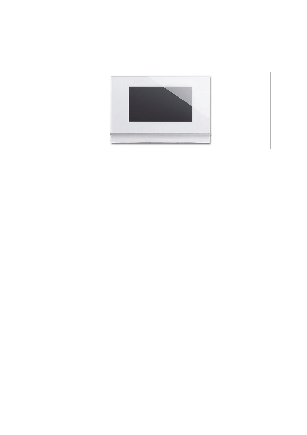
4 Product description
Fig. 1: Product overview
The Busch-SmartTouch
communication system and the display and operation of standard KNX functions 19). It has a
capacitive touch display with 1024 x 600 pixel.
The product is part of the ABB-Welcome
with the components of this system.
The touch panel is linked with both bus systems, the ABB i-bus
bus. The audio/video signals are transmitted and the power for the device is supplied
exclusively via the ABB-Welcome
control system or one additional power supply is to be provided to ensure the power supply for
the touch panel.
It is also possible to operate the touch panel without a connection to the ABB-Welcome
This means that an additional power supply is to be provided to ensure the power supply for the
touch panel.
®
7'' serves as indoor video station for the ABB-Welcome® door
Product description
®
door communication system and operates exclusively
®
KNX and the ABB-Welcome®
®
bus. This means that at least one ABB-Welcome® central
®
bus.
Up to 16 KNX functions can be positioned on one operating page. And up to 30 operating pages
with a total of 480 control elements are possible. The room temperature controller and the
scene control element each occupy two function positions. The audio control element occupies
at least four function positions.
The device can also be used for fault and alarm messages.
The KNX touch panel is configured with the DCA commissioning tool. The DCA is integrated in
the ETS and makes direct access to group addresses and flags of communication objects
possible. The control element consists of freely programmable touch surfaces.
Product manual 2CKA001473B9264
18
Page 19
│
4.1 Scope of supply
The panel is included in the scope of supply. It further includes a micro SD card (SDHC) with
adapter, e.g. for the slot of a PC.
The enclosed bus connection terminal serves for the connection with the ABB i-bus
and/or the ABB-Welcome
®
bus.
The special Surface-mounted mounting frame (6136/27-xxx-500) and the associated Flushmounted installation box (6136/07 UP-500; windproof) are not included in the scope of supply.
The necessary power adapters (e.g. CP-D 24/2.5) are also not included in the scope of supply.
4.2 Additional necessary components
■
Power adapter for the 20 - 32 V DC (SELV) auxiliary power supply (power supply of device)
or the central control system ABB-Welcome
this case).
■
Associated flush-mounted installation box or surface-mounted mounting frame (if the device
is not mounted on the associated flush-mounted installation box).
Product description
®
KNX
®
(no additional power supply is necessary in
4.3 Overview of types
Article no. Product name Colour Display diagonal
6136/07-811-500 Busch-SmartTouch® 7'' White 17.8 cm (7“)
6136/07-825-500 Busch-SmartTouch® 7'' Black 17.8 cm (7“)
Table 1: Overview of types
4.4 Overview of KNX functions
The following table provides an overview of the possible functions and applications of the
device:
Standard KNX functions Applications
■
Switching
■
Dimming
■
Slide controller functions
■
Blind control
■
RGBW operation
■
Fan control (step switching)
■
Scene control
■
Display functions (display elements)
■
Room temperature controller (RTC)
■
Page link functions
■
Audio control
Table 2: Overview of functions
■
Door communication
■
Fault and alarm messages
■
Scene actuator
■
Presence simulation
■
Time programs
■
Logical functions
■
Internal RTC
Product manual 2CKA001473B9264
19
Page 20
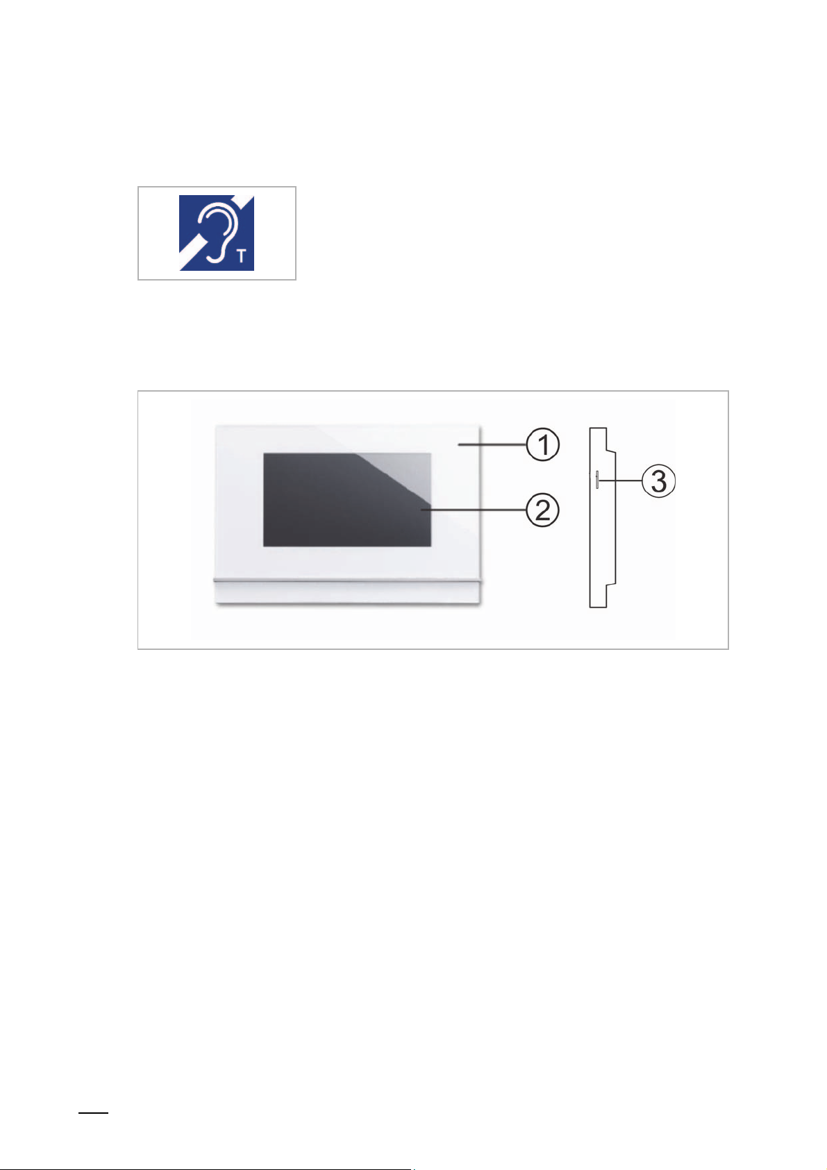
│
4.5 Additional function of hearing loop
The device is equipped with a hearing loop for coupling the audio signals with hearing aids.
To be able to use such hearing loops, the hearing aid must
have a so-called telephone coil ("T-coil" for short), which
takes up the magnetic alternating field of the hearing loop.
Normally the microphone of the hearing aid is deactivated
when the telephone coil is in use.
The maximum distance to the device for optimum reception
should be 80 cm.
4.6 Device overview
Product description
Fig. 2: Overview of device Busch-SmartTouch® 7''
[1] Front of device
[2] Touch-sensitive user interface
[3] Slot for micro SD card (SDHC)
Product manual 2CKA001473B9264
20
Page 21

│
5 Technical data
Designation Value
Display resolution 1024 x 600 pixel
Aspect ratio 16:9
Colour resolution 16 million colours
Display size 17.78 cm (7")
Viewing angle
– Horizontal:
– Vertical:
Background illumination LED
Maximum brightness ±240 cd/m2
Service life
Touch technology
– Calibration:
Technical data
80° / 80°
> 70° / 60° minimal viewing angle at 12 o'clock
±20 000 h
(at maximum brightness of > 125cd/m
Capacitive
Automatic
2
)
Operating temperature -5°C - +45°C
Storage temperature 20°C - +70°C
Protection IP20
Single-wire clamps 2 x 0.6 mm2 - 2 x 1 mm2
Fine-wire clamps 2 x 0.6 mm2 - 2 x 0.75 mm2
Mains supply
(Welcome bus voltage or nominal voltage)
20 V - 32 V DC
KNX bus voltage 21 V - 32 V DC
Energy consumption (power input)
– Maximum:
– Standby:
< 9.5 W
< 3 W
KNX bus connection terminal 0.6 mm - 0.8 mm single-wire
Micro SD card (SDHC) Slot for micro SD card
Commissioning
– Parameter setting:
– Programming:
Table 3: Technical data
ETS 5
Via KNX bus or micro SD card
Product manual 2CKA001473B9264
21
Page 22
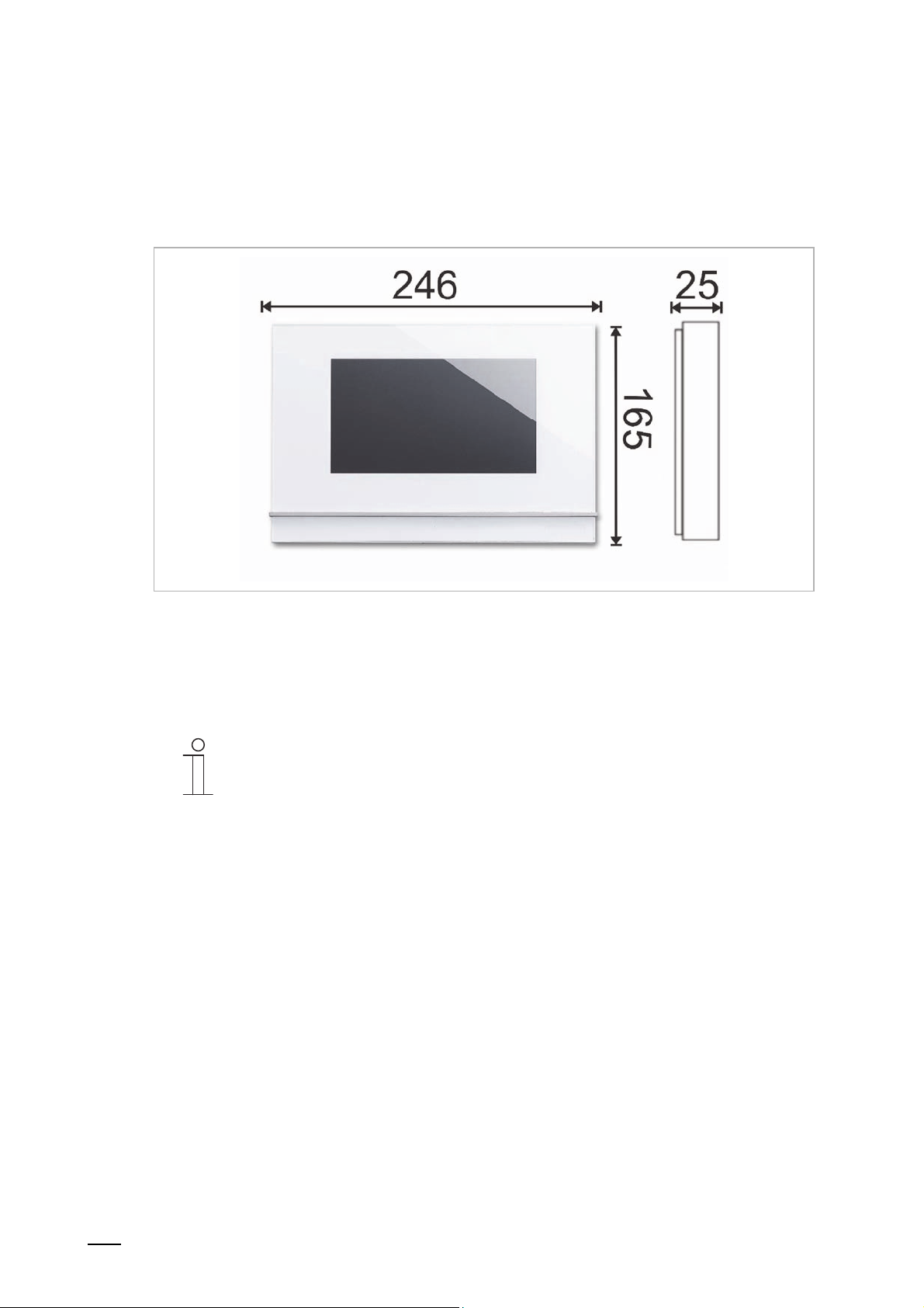
│
Circuit diagrams and dimensional drawings
6 Circuit diagrams and dimensional drawings
6.1 Dimensional drawings
Fig. 3: Dimensions of all described device types
All dimensions are in millimetres.
The installation height of the device is 13 mm.
The installation depth is 15 mm.
Note
The dimensions of the associated flush-mounted installation boxes (not included
in the scope of supply) are as follows:
■
Dimension for flush-mounting (H x W x D): 152 x 235 x 60.
■
Dimension for hollow wall mounting (H x W x D): 146 x 227 x 50.
The dimensions of the surface-mounted mounting frame (not included in the
scope of supply) are as follows:
■
(H x W x D): 165 x 246 x 12
Product manual 2CKA001473B9264
22
Page 23
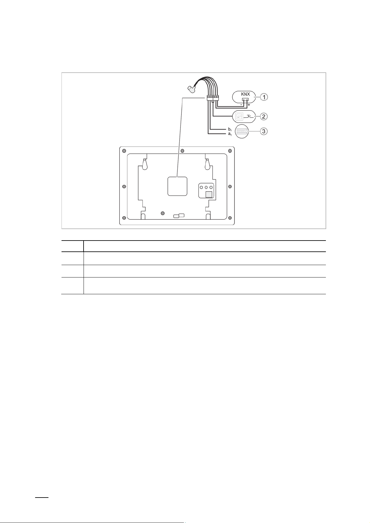
│
6.2 Circuit diagrams
Circuit diagrams and dimensional drawings
Fig. 4: Electrical connection
No. Function
1 Connection for the ABB i-bus® KNX
2 Connection for the floor call button
3
Table 4: Function of connection
Connection for the central control system or external power supply (e.g. CP-D 24/2.5)
When using several indoor stations: connection for the internal bus.
Product manual 2CKA001473B9264
23
Page 24
│
Connection, installation / mounting
7 Connection, installation / mounting
7.1 Planning instructions
Notice
Notes on planning and application for ABB-Welcome
the system manual for ABB-Welcome
www.BUSCH-JAEGER.com.
7.2 Safety instructions
Danger - Electric shock due to short-circuit!
Risk of death due to electrical voltage of 100 to 240 V during short-circuit in the
low-voltage line.
– Low-voltage and 100 - 240 V lines must not be installed together in a flush-
mounted box!
– Observe the spatial division during installation (> 10 mm) of SELV electric
circuits to other electric circuits.
– If the minimum distance is insufficient, use electronic boxes and insulating
tubes.
– Observe the correct polarity.
– Observe the relevant standards.
Danger - Electric voltage!
Install the device only if you have the necessary electrical engineering
knowledge and experience.
■
Incorrect installation endangers your life and that of the user of the electrical
system.
■
Incorrect installation can cause serious damage to property, e.g. due to fire.
The minimum necessary expert knowledge and requirements for the installation
are as follows:
■
Apply the "five safety rules" (DIN VDE 0105, EN 50110):
1. Disconnect
2. Secure against being re-connected
3. Ensure there is no voltage
4. Connect to earth and short-circuit
5. Cover or barricade adjacent live parts.
■
Use suitable personal protective clothing.
■
Use only suitable tools and measuring devices.
■
Check the type of supply network (TN system, IT system, TT system) to
secure the following power supply conditions (classic connection to ground,
protective earthing, necessary additional measures, etc.).
®
. This can be downloaded at
®
systems are available in
Product manual 2CKA001473B9264
24
Page 25
│
7.3 Preparatory steps
■
Terminate all branches of the line network via a connected bus device (e.g. indoor station,
outdoor station, system device).
■
Do not install the central control system directly next to bell transformers and of other
switched voltage supplies (avoidance of interference).
■
Do not install the cables of the system bus together with 100 - 240 V cables.
■
Do not use joint cables for the connecting lines of door openers and lines of the system bus.
■
Avoid junctions between different cable types.
■
In a four- or multi-core cable, use only two wires for the system bus.
■
During looping, never install the incoming and outgoing bus within a cable.
■
Never install the internal and external bus within a cable.
7.4 Mounting
The device is suited for flush-mounted and surface-mounted installation.
The surface-mounted mounting frame (6136/27-xxx-500; not part of the scope of supply) can be
used for surface mounting when the device is not mounted on the associated flush-mounted
installation box.
Connection, installation / mounting
The following mounting versions are possible:
– on a standard flush-mounted box (e.g. 3040)
– on an old control panel box 6136/UP-500 (MD/U 1.1)
– directly on the wall
– on Table stand 83506-500
The associated Flush-mounted installation box (6136/07 UP-500; not included in the scope of
supply) can be used in hollow walls. Can also be used in solid walls. For this, part of the box
must first be inserted flush-mounted.
Note
Detailed information is available in the enclosed installation instructions for the
surface-mounted mounting frame and the associated flush-mounted installation
box.
Note
The mounting height is 1.50 m.
Product manual 2CKA001473B9264
25
Page 26
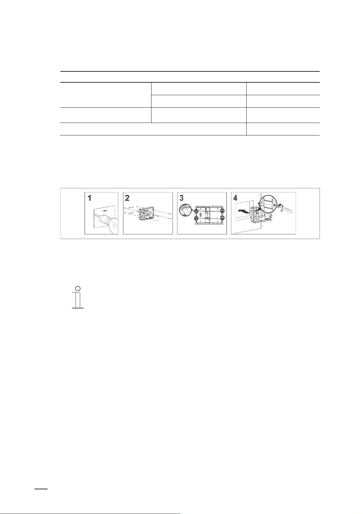
│
Connection, installation / mounting
7.4.1 Overview of mounting versions
Mounting versions, connection and installation of Busch-SmartTouch® 7''
Mounting in flush-mounted
installation box
Mounting with surface-mounted
mounting frame
Hollow wall See Page 26
Solid wall See Page 27
Surface-mounted mounting frame See Page 28
Connection and installation See Page 31
Table 5: Mounting versions, connection and installation
7.4.2 Mounting in flush-mounted installation box in hollow wall
Installation on the basis of the instructions on the enclosed drilling template:
Fig. 5: Mounting in hollow wall
Continue with connection and installation 31.
Notice
See mounting instructions on the enclosed plaster and drilling template.
The bottom part of the flush-mounted installation box in not required here.
Product manual 2CKA001473B9264
26
Page 27
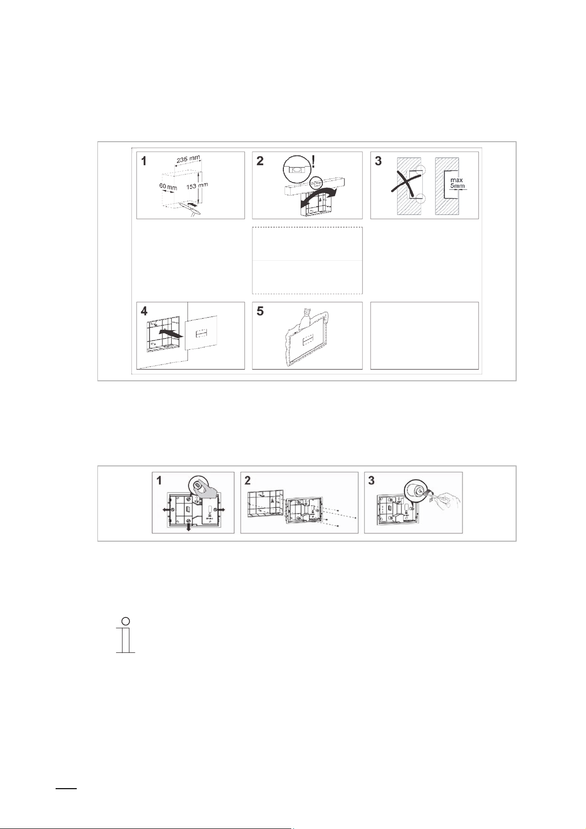
│
Connection, installation / mounting
7.4.3 Mounting in flush-mounted installation box in solid wall
Installation on the basis of the instructions on the enclosed plastering template:
Fig. 6: Mounting in solid wall
The following working steps must be carried out after the bottom part of the installation box has
been installed flush-mounted.
Installation on the basis of the instructions on the enclosed drilling template:
Fig. 7: Mounting the top part of the flush-mounted installation box
Continue with connection and installation 31.
Notice
See mounting instructions on the enclosed plaster and drilling template.
First the bottom part of the flush-mounted installation box must be pulled off and
installed flush-mounted.
Product manual 2CKA001473B9264
27
Page 28
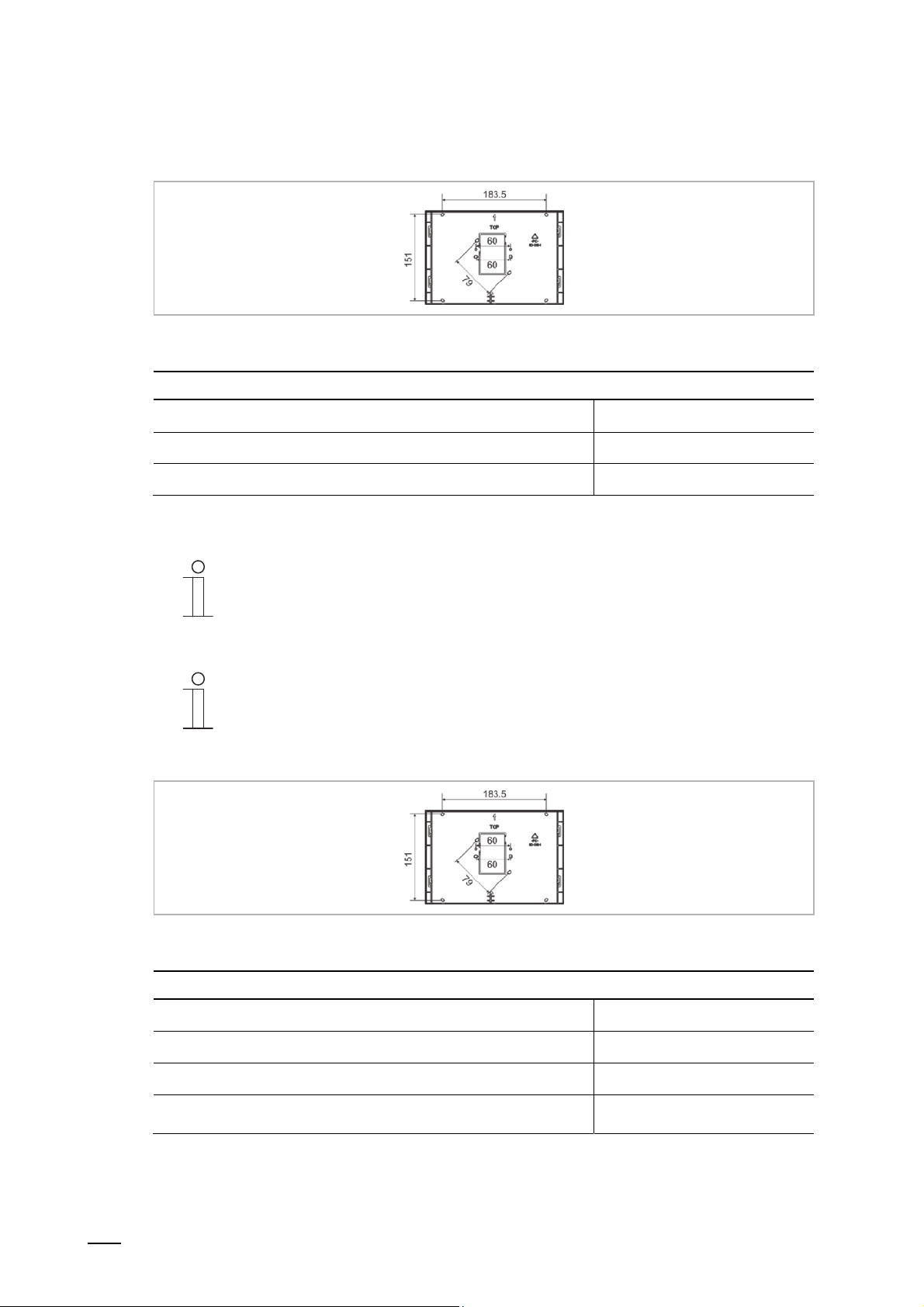
│
Connection, installation / mounting
7.4.4 Mounting with surface-mounted mounting frame
Fig. 8: Installation of surface-mounted mounting frame
Mounting version in combination with the surface-mounted mounting frame
Standard flush-mounted box 30
Old control panel box 6136/UP-500 (MD/U 1.1) 30
Table stand 83506-500 30
Table 6: Mounting version of surface-mounted mounting frame
Notice
See the enclosed mounting instructions.
Notice
First, depending on the mounting version according to the following
specifications, the surface-mounted mounting frame must be installed:
Fig. 9: Installation of surface-mounted mounting frame
Mounting version in combination with the surface-mounted mounting frame
Standard flush-mounted box 30
Old control panel box 6136/UP-500 (MD/U 1.1) 30
Table stand 83506-500 30
Swiss flush-mounted box
Table 7: Mounting version of surface-mounted mounting frame
Fehler! Textmarke nicht
definiert.
Product manual 2CKA001473B9264
28
Page 29

│
Notice
See the enclosed mounting instructions.
Notice
First, depending on the mounting version according to the following
specifications, the surface-mounted mounting frame must be installed:
Connection, installation / mounting
Product manual 2CKA001473B9264
29
Page 30
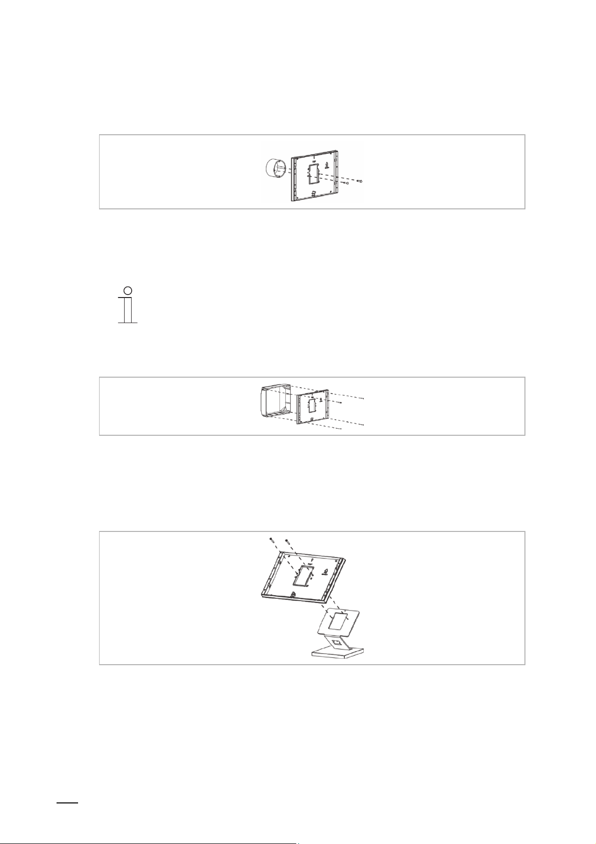
│
7.4.5 Standard flush-mounted box
(E.g. 3040)
Fig. 10: Standard flush-mounted box / direct on the wall
Continue with connection and installation 31.
Notice
A hole for the cable gland should be available.
Connection, installation / mounting
7.4.6 Old control panel box 6136/UP-500 (MD/U 1.1)
Fig. 11: Old control panel box 6136/UP-500 (MD/U 1.1)
Continue with connection and installation Page 31.
7.4.7 Table stand 83506-500
Fig. 12: Table stand 83506-500
Continue with connection and installation Page 31.
Product manual 2CKA001473B9264
30
Page 31

│
7.4.8 Connection and installation
Fig. 13: Connection
Connection, installation / mounting
1. Connect the device according to the
graphics (23).
Fig. 14: Setting the address of the outdoor station
2. Set the address of the preferred
outdoor station and the address of
the indoor station via the rotary
switches on the rear of the housing
(154).
3. Set the master / slave function and
the terminating resistor via the
switches on the rear of the housing
(153).
Fig. 15: Setting the master / slave function and
terminating resistor
Product manual 2CKA001473B9264
31
Page 32

│
Connection, installation / mounting
4. Snap the device onto the installation
box according to the mounting
version.
5. Insert the snap noses into the
holders.
Fig. 16: Snapping the device on, surface-mounted
and flush-mounted box
6. Press the device downward until the
bottom clamp latches in.
Fig. 17: Latching the device
The device is now fully mounted.
7.5 Dismantling
The clamp of the device can be easily loosened.
Fig. 18: Clamp of device
1. Push the slider on the bottom side of the device to the right.
– The clamp is loosened.
2. Push the device upwards and then pull it off toward the front.
Product manual 2CKA001473B9264
32
Page 33

│
8 Initial commissioning
Initial commissioning follows the successful mounting and installation. For this the current
Firmware, which is located on the enclosed micro SD card, must be installed.
After switching on the power supply the device starts automatically and the application is being
prepared.
Note
For the transfer of data to the device via the micro SD card both power supplies
must be switched on!
1. Follow the instructions on the screen.
Initial commissioning
Fig. 19: Start screen of initial commissioning
2. Insert the enclosed micro SD card into the device, 148.
– The following note will appear briefly on the display: "Firmware updating will start,
please wait…".
– The application starts automatically.
Product manual 2CKA001473B9264
Note
Observe the animation of the micro SD card on the screen.
Note
The duration of initial commissioning with this application takes around
10 minutes. The duration is displayed on the screen.
33
Page 34

│
Initial commissioning
Fig. 20: Duration of initial commissioning
The following messages can appear on the screen after the installation.
Installation successful Installation unsuccessful
3. Remove the micro SD card.
You can now program the device, 78 or .
Table 8: Messages after the installation
3. Repeat process. To do this, remove the panel
from the power supply and then reconnect it.
If there is no img file on the card, for example,
the message "No valid image file" is
displayed.
Product manual 2CKA001473B9264
34
Page 35

│
Commissioning via DCA (from ETS5)
9 Commissioning via DCA (from ETS5)
Commissioning the Busch-SmartTouch® 7'' via the plug-in ETS5 commissioning tool DCA.
9.1 Integration into the KNX system (ETS)
Note
The device meets KNX guidelines and can be used as product of the KNX
system. Detailed expert knowledge for understanding by means of KNX training
9.1.1 Installation of the Busch-SmartTouch
For the display of the commissioning tool DCA, a special app must be installed.
This app can then be called up in the ETS via an additional tab (DCA). For this a licensed
version of the ETS Professional Software must be installed on the target computer for the
installation. At least Version ETS7.2 is required.
is assumed, especially with regard to the commissioning software ETS.
®
ETS app
Notice
■
The app for the ETS5 can be downloaded via the electronic catalogue
(www.busch-jaeger-catalogue.com).
■
The apps are called up on the start page of the ETS via "App" (bottom right).
Product manual 2CKA001473B9264
35
Page 36

│
9.1.2 Installation sequence
The ETS5 app (etsapp file, ABB Touch DCA) for the Busch-SmartTouch
ETS.
The app can be downloaded either via www.BUSCH-JAEGER.com or via the My KNX access.
Commissioning via DCA (from ETS5)
®
7'' is installed via the
Fig. 21: Installation of the app
9.1.3 Integrating the Busch-SmartTouch
®
7'' into the ETS
1. Start the ETS.
2. Import the product data of the Busch-SmartTouch
import function of the ETS (File type: *.knxprod).
9.1.4 Further KNX settings in the Busch-SmartTouch
All KNX settings for the Busch-SmartTouch
®
7'' are made via the DCA commissioning tool.
®
7'' into the project database via the
®
7''
Product manual 2CKA001473B9264
36
Page 37

│
Commissioning via DCA (from ETS5)
9.2 Overview of the DCA commissioning tool
The following section includes basic information about the DCA commissioning tool.
DCA is a project planning software with which you can configure the Busch-SmartTouch
the ABB building automation. Every Busch-SmartTouch
leads you through the configuration during project planning.
Essential tasks during project planning with DCA are:
■
Specifying fundamental settings, e.g. display language for the Busch-SmartTouch® 7'' (basic
settings).
■
Specifying the navigation structure, e.g. creation of floors and rooms with associated
operating pages.
■
Configuration of existing applications.
■
Configuration of pages, e.g. arrangement of buttons.
■
Configuration of control elements, e.g. selection of button icons.
■
Linking with group addresses to establish the connection to actuators and sensors via the
bus.
9.2.1 Starting the DCA
®
7'' can be set up individually. DCA
®
7'' for
1. Start the ETS software (double-click on the program icon or via the start menu of the
operating system (Start -> Programs -> KNX -> ETS5)).
– The overview window of the ETS opens.
2. Open an existing project file or create a new project.
– The main window of the ETS opens.
Note
Detailed knowledge of ETS operation is assumed for project planning.
It is recommended to first import the product data into the project database
(See “Integrating the Busch-SmartTouch
3. Integrate the device into the project via the catalogue.
4. Select the device.
5. Click on "DCA" above the status bar.
– DCA opens inside the list view of the ETS.
®
7'' into the ETS “ on page 36).
Product manual 2CKA001473B9264
37
Page 38

│
9.3 Screen areas of the DCA
During project planning with DCA you work in several areas. In this section the purpose the
screen areas serve is explained and how they are to be handled.
Commissioning via DCA (from ETS5)
Fig. 22: DCA screen areas
Product manual 2CKA001473B9264
38
Page 39

│
Commissioning via DCA (from ETS5)
Pos. Screen area Function
[1] DCA icon bar
Quick access to different DCA tools, e.g. "Importing"
or "Exporting"
The desired "Control elements" can be pulled via drag
[2] "Control elements" area
and drop from this area onto the operating pages in
the work area.
Only the available control elements are displayed
Makes available corresponding input and output
options in the work area depending on the selected
[3] "Parameter" area
control element.
The applications and general settings for the panel
can be configured here (see library area)
[4] "Group addresses" area Area for managing and creating group addresses
Listing of available communication objects of the
marked control elements (see work area).
[5] "Communication objects" area
Here communication objects can be selected and
edited via the ETS. The same applies to several
applications (see library area)
Graphically displays the operating pages created in
the library area. This is also the way the pages are
displayed on the panel.
Control elements can be pulled via drag and drop
from the "Control elements" area onto the operating
[6] Work area with icon bar
pages and marked there.
The setting options for marked elements are
displayed in the "Parameter" area.
Direct functions can be carried out for the marked
elements via the icon bar.
The arrow buttons can be used to "swipe" up or
down, the same as on the panel
[7] Device menu bar
Opens the lists of the "Communication objects",
"Channels" and "Parameters" for the device
"Navigation" tab: Includes a tree structure of the
entire project. Here floors, rooms and operating
pages can be added. Also general settings for the
[8] Library area
panel can be selected here and configured in the
"Parameter" area.
The same applies to "Applications" tab. Here the
available applications can be selected and configured
in the "Parameter" area
Table 9: DCA screen areas
Notice
The size of areas 4, 5, 6 and 8 can be changed by pulling the black frame while
keeping the mouse button pressed.
Product manual 2CKA001473B9264
39
Page 40

│
Commissioning via DCA (from ETS5)
9.4 Explanation of the basic structure (Terms)
The panel comprises:
■
a main operating page (homepage)
■
operating pages for rooms
■
operating pages for floors and corridors
■
application pages
Fig. 23: Panel with control elements
The main operating page is displayed after the device has started and is marked with a star in
the navigation structure in the library area.
The operating pages for rooms include control elements of the associated rooms, such as
switches, dimmers or scenes.
The operating pages for floors contain the associated operating pages for rooms.
The application pages ("Application" tab) contain applications, such as door communication,
fault and alarm messages.
Basically all operating pages (start pages) can be freely configured and need not be allocated to
a specific room.
You can position control elements (homepage, start pages) on all operating pages to carry out
house and device functions. Additional operating pages can be displayed via the "Page link"
control element. The bottom bar of the panel indicates whether several pages are available.
To call up preferred control elements directly, you can compile favourites in a favourites list.
Applications and application pages can be activated on the application pages.
Product manual 2CKA001473B9264
40
Page 41

│
Navigation
If you swipe to the right on the main operating page of the Busch-SmartTouch
configured application pages and basic settings are displayed in a menu.
If you swipe to the left on the main operating page, the created operating pages are displayed.
If several operating and application pages have been created on a level, you can call them up
by swiping to the left or to the right.
Notice
Additional explanations are available in Chapter 11 “Operation“ on page 119.
Commissioning via DCA (from ETS5)
®
7'', the
Product manual 2CKA001473B9264
41
Page 42

│
Commissioning via DCA (from ETS5)
9.5 Commissioning sequence
To be able to work with the DCA commissioning tool as effectively as possible, the following
work sequence (standard workflow) is recommended:
1. Start the ETS software (See “Starting the DCA“ on page 37).
2. Create a new project or open an existing one.
3. Start the DCA
4. Configure basic settings for the panel.
5. Create the navigation structure (See “Creation of the navigation structure“ on page 56).
6. Configure the operating pages (insert and configure control elements).
7. Configure the applications and application pages.
8. Edit the available communication objects.
9. Create group addresses and allocate the correct data point type (DPT) to all group
addresses used in the Busch-SmartTouch
10. Transfer the project to the panel and start operation.
9.6 Configuring basic settings for the panel
®
7'' (e.g. function: 1.001 switch).
The basic settings for the panel can be specified beforehand.
1. Open the "Applications" tab in the library area.
2. Open "System settings".
– The basic settings are displayed in the "Parameter" area and can be edited (See “Basic
settings (system settings) of the panel“ on page 43).
– Available communication objects for certain functions are displayed in the
"Communication objects" area and can be used.
– Group addresses can be allocated via the "Group addresses" area.
Note
Some basic settings can be adjusted directly in the panel. For this the setting
"Enable system settings for end customers" must be set on "Yes".
Product manual 2CKA001473B9264
42
Page 43

│
Commissioning via DCA (from ETS5)
9.6.1 Basic settings (system settings) of the panel
Notice
Entries in text fields must be confirmed with the return key.
Common
■
Panel language
Options: <Selection of language from a list>
The parameter is used to specify the language of the user interface.
Selection:
1. Click on the arrow.
– The list with available languages opens.
2. Select the language.
■
Acoustic signal at press of button
Options: Deactivated
Activated
The parameter is used to specify whether an acoustic signal is issued by the device when a
button is pressed.
■
Default setting of volume of acoustic signal [%]
Options: Setting option from 10 to 100%
The parameter is used to set the volume for the acoustic signal when a button is pressed.
Entry:
1. Click in the input field and enter a percentage.
Or:
1. Click on the arrows.
Notice
The parameter is available only if the "Acoustic signal at press of button" is
activated.
Product manual 2CKA001473B9264
43
Page 44

│
■
Decimal separator
Options: Comma
The parameter is used to specify whether a comma or a dot is used as decimal separator.
■
Thousands separator
Options: Comma
The parameter is used to specify whether thousands are separated with a comma or a dot.
■
Time format
Options: 12 h
The parameter is used to specify in which format the time is displayed. The default setting is
the 24-hour display.
■
Date format
Options: DD-MM-YY
DD/MM/YY
YY-MM-DD
YY.MM.DD
The parameter is used to specify the date format.
Selection:
1. Click on the arrow.
– The list with available date formats opens.
2. Select date format.
DD: Day, MM: Month, YY: Year. Example: 01-12-17 (DD-MM-YY)
Commissioning via DCA (from ETS5)
Dot
Dot
24 h
MM/DD/YY
Product manual 2CKA001473B9264
44
Page 45

│
■
Sending/receiving time and date
Options: No sending and no receiving
Only receiving
The device has an internal date and time module. The parameter is used to set how the
device uses the date and time.
– No sending and no receiving: The device uses date and time only internal.
– Only sending: The device synchronizes additional KNX components in the system.
– Only receiving: The device receives date and time from a separate KNX-DCF module.
If you select "Only sending" or "Only receiving", the date and time can be synchronized via a
communication object. The synchronization is carried out by sending a group address to or
from the device.
Link the communication objects "Time output" and "Date output" with a corresponding group
address.
Selection:
1. Click on the arrow.
– The list with available settings opens.
2. Select the setting.
■
Automatic summer/winter time changeover
Options: Deactivated
The parameter is used to specify whether the changeover to summer/winter time is
automatic.
Commissioning via DCA (from ETS5)
Only sending
Activated
Product manual 2CKA001473B9264
45
Page 46

│
■
Sending time and date
Options: Every minute
Every 12 hours
At 00:00
At 00:02
At summer/winter time changeover
At 00:00 + summer/winter time changeover
At 00:02 + summer/winter time changeover
The parameter is used to specify the time interval at which the device sends the date and
time.
Notice
The parameter is available only when parameter "Send/receive time and
date" is set on "Only sending".
Selection:
1. Click on the arrow.
– The list with available time intervals opens.
2. Select time interval.
■
First day of the week
Options: Saturday
Monday
The parameter is used to specify the weekday with which the week starts.
Selection:
1. Click on the arrow.
– The list with available weekdays opens.
2. Select weekday.
Commissioning via DCA (from ETS5)
Every hour
Sunday
Product manual 2CKA001473B9264
46
Page 47

│
■
Lat. [dd.dd][+ = North, − = South]
Options: Setting option from +90.00 to -90.00
Commissioning via DCA (from ETS5)
The parameter is used to set the geographic latitude for the location of the device (90° North
to 90° South)
This setting is important for the astro function. The entry is made in decimal degrees. The
minutes and seconds must be converted for the entry.
One degree corresponds to 60 minutes.
Example:
51° 14′ 53" North (51 degrees, 14 minutes and 53 seconds North) = +51.25 decimal
degrees
Example of calculation:
53' (seconds) divided by 60 = 0.88' minutes
14' (minutes) + 0.88' (minutes) = 14.88' (minutes)
14.88' (minutes) divided by 60 = 0.248' (degrees)
51° (degrees) + 0.248° (degrees) = 51.248° (degrees)
Entry:
1. Click in the input field.
2. Enter the coordinates according to the example.
■
Long. [ddd.dd][+ = East, − = West]
Options: Setting option from +180.00 to -180.00
The parameter is used to set the geographic longitude for the location of the device (180°
East to 180° West)
This setting is important for the astro function. The entry is made in decimal degrees. The
minutes and seconds must be converted for the entry.
One degree corresponds to 60 minutes.
Example:
7°36′ 13' East (7 degrees, 34 minutes 13 seconds East) = +7.60 decimal degrees
Example of calculation:
13' (seconds) divided by 60 = 0.22' minutes
36' (minutes) + 0.22' (minutes) = 36.22' (minutes)
36.22' (minutes) divided by 60 = 0.603' (degrees)
7° (degrees) + 0.603° (degrees) = 7.603° (degrees)
Entry:
1. Click in the input field.
2. Enter the coordinates according to the example.
Product manual 2CKA001473B9264
47
Page 48

│
Display
■
Display brightness [%]
Options: Setting option from 10 to 100%
The brightness of the display is set via the parameter.
Entry:
1. Click in the input field and enter a percentage.
Or:
1. Click on the arrows.
■
Activating the automatic return to the start screen
Options: Deactivated
The parameter is used to specify whether the panel returns automatically to the main
operating page (homepage). If the function is activated, the return takes place during
inactivity on the device after a preset rest period.
■
Return to the start screen after … [sec.]
Options: Setting option from 10 - 3600 seconds
The parameter is used to set the rest period after which the device returns to the main
operating page (homepage).
Entry:
1. Click in the input field and enter a time value (in seconds).
Or:
1. Click on the arrows.
■
Switching the display off [min.]
Options: Display always on
10
15
30
60
120
The parameter is used to specify whether or when the display switches off after the last
actuation. The display switches back on after a renewed actuation of the touch screen.
Selection:
1. Click on the arrow.
– The list with available time intervals (in minutes) opens.
2. Select time interval.
Commissioning via DCA (from ETS5)
Activated
5
Product manual 2CKA001473B9264
48
Page 49

│
■
Display screen saver [min.]
Options: No screen saver
10
15
30
60
120
The parameter is used to specify whether or when the screen saver is displayed after the
last actuation. The screen saver is faded out again after a renewed actuation of the touch
screen.
Selection:
1. Click on the arrow.
– The list with available time intervals (in minutes) opens.
2. Select time interval.
■
Screen saver mode
Options: Clock
Weather data
The parameter is used to specify the visualization that is displayed as screen saver. Depending
on the mode, there are additional tailor-made setting options.
Notice
For selecting the "Slide show": The images for the screen saver must be
located on the micro SD card in the "Slide" folder. The card must remain
inserted in the device. Additional details on the screen saver are available in
Chapter 11.7 “System settings“ on page 148.
Selection:
1. Click on the arrow.
– The list with available modes opens.
2. Select the mode.
■
Type of clock
Options: Analog
The parameter is used to specify the visualization of the clock.
Notice
The parameter is available only when parameter "Screen saver mode" is set
on "Clock".
Commissioning via DCA (from ETS5)
5
Slide show
Digital
Product manual 2CKA001473B9264
49
Page 50

│
■
Display of seconds
Options: Deactivated
During the analogue visualization a seconds hand and during digital visualization the
seconds are displayed via the parameter.
Notice
The parameter is available only when parameter "Screen saver mode" is set
on "Clock".
■
Effect of picture transfer
Options: Shift from the right
The parameter is used to specify the slide transition effect for the display of slides.
Notice
The parameter is available only when parameter "Screen saver mode" is set
on "Display of slides".
■
Slide show interval
Options: Setting option from 5 - 120 seconds
The parameter is used to specify how long an image of the screen saver is displayed before
the next image appears.
Entry:
1. Click in the input field and enter a time value (in seconds).
Or:
1. Click on the arrows.
Notice
The parameter is available only when parameter "Screen saver mode" is set
on "Display of slides".
■
Order of slides
Options: At random
The parameter is used to specify whether the slides of the screen saver are displayed in an
alphabetical sequence according to file name or at random.
Notice
The parameter is available only when parameter "Screen saver mode" is set
on "Display of slides".
Commissioning via DCA (from ETS5)
Activated
Fade out
Alphabetically
Product manual 2CKA001473B9264
50
Page 51

│
■
Display of outside temperature
Options: Deactivated
Activated
Commissioning via DCA (from ETS5)
The parameter is used to display weather data and environmental data in screen saver
mode, e.g. the outdoor temperature. For this, link the associated communication object with
one group address respectively.
Notice
The parameter is available only when parameter "Screen saver mode" is set
on "Weather data".
■
Display rain
Options: Deactivated
Activated
The parameter is used to display weather data and environmental data in screen saver
mode, e.g. rain data. For this, link the associated communication object with one group
address respectively.
Notice
The parameter is available only when parameter "Screen saver mode" is set
on "Weather data".
■
Display wind force
Options: Deactivated
Activated
The parameter is used to display weather data and environmental data in screen saver
mode, e.g. the wind force. For this, link the associated communication object with one group
address respectively.
Notice
The parameter is available only when parameter "Screen saver mode" is set
on "Weather data".
■
Display brightness
Options: Deactivated
Activated
The parameter is used to display weather data and environmental data in screen saver
mode, e.g. the brightness. For this, link the associated communication object with one group
address respectively.
Notice
The parameter is available only when parameter "Screen saver mode" is set
on "Weather data".
Product manual 2CKA001473B9264
51
Page 52

│
Temperature
Notice
The temperature parameters refer to the temperature display in the bottom bar
of the display.
■
Unit of temperature
Options: °C
The parameter is used to specify the display of the temperature in units of °C (Celsius) or °F
(Fahrenheit).
■
Display room temperature
Options: Deactivated
The parameter is used to specify whether the current measured temperature value of the
indoor temperature sensor is displayed.
■
Display of outside temperature
Options: Deactivated
The parameter is used to specify whether the current measured temperature value of an
outdoor temperature sensor, which has been allocated via a group address, is displayed.
■
Room/outdoor temperature change interval [sec.]
Options: Setting option from 3 - 10 seconds
Room and outdoor temperature share a display location in the bottom bar of the display.
The parameter is used to specify the time after which the display of the temperatures
changes.
Entry:
1. Click in the input field and enter a time interval (in seconds).
Or:
1. Click on the arrows.
Product manual 2CKA001473B9264
Commissioning via DCA (from ETS5)
°F
Activated
Notice
Room and outdoor temperature share a display location in the bottom bar of
the display. They are displayed alternately when both parameters are
activated.
Activated
Notice
Room and outdoor temperature share a display location in the bottom bar of
the display. They are displayed alternately when both parameters are
activated.
Notice
The parameter is available only when parameter "Display room temperature"
is activated.
52
Page 53

│
■
Use for room temperature sensor
Options: Indoor sensor
Outdoor sensor
Commissioning via DCA (from ETS5)
The parameter is used to specify whether the room temperature is measured via the indoor
sensor of the device or via an outdoor KNX temperature sensor.
The outdoor sensor must be allocated via a group address.
■
Compensating value for temperature measurement (x 0.1K) [K]
Options: Setting option from -127 - +127 K
The parameter is used to specify the value by which the measured temperature is raised or
lowered. This compensating value ensures that the correct temperature is displayed and, if
necessary, passed on to other devices. A compensation, for example, is necessary when
adjoining heat sources distort the measured result.
Entry:
1. Click in the input field and enter a compensating value (in Kelvin).
Or:
1. Click on the arrows.
Notice
The parameter is available only when parameter "Use for room temperature
sensor" is set on "Indoor sensor".
■
Send indoor sensor temperature
Options: Do not send
During change
Cyclic
During change and cyclic
The parameter is used to specify whether or when the temperature values of the indoor
sensor are passed on to other devices.
■
Cycle time for automatic transmission of the internal sensor temperature [sec.]
Options: Setting option from 5 - 3600 seconds
The parameter is used to specify the intervals at which the temperature values of the indoor
sensor are passed on to other devices.
Product manual 2CKA001473B9264
53
Page 54

│
Commissioning via DCA (from ETS5)
Safety
Certain areas of the Busch-SmartTouch
®
7'', e.g. operating pages, can be protected against
unauthorized access. The access protection is indicated in the display by means of a lock
symbol in the bottom bar.
When actuating a control element or an application when the access protection is activated, the
user must first enter a security number (PIN code) to enable the function.
■
Length of the PIN code
Options: 4 digits
5 digits
6 digits
The parameter is used to specify the number of digits of the PIN code.
■
PIN codes can be changed by the end customer
Options: Deactivated
Activated
The parameter is used to specify whether the PIN codes can be changed by the end
customer. They can then be changed by the customer directly on the device. This function
can be protected by a code (see parameter "Enable system settings for end customers").
■
Enable system settings for end customer
Options: Yes
With code
The parameter is used to specify how the end customer can access the system settings of
the device. The access can be protected by a code.
– Yes: Access to the system settings without code.
– With code: Access to the system settings with code. The code is specified in parameter
"Code for system settings [0000xx - 9999xx]".
■
Code for system settings [0000xx - 9999xx]
Options: Setting option from 0000xx - 9999xx
The parameter is used to specify the code for access to the system settings.
Entry:
1. Click in the input field and enter a 4-, 5-, or 6-digit code.
Notice
The length of the code is specified via parameter "Length of PIN code".
Product manual 2CKA001473B9264
54
Page 55

│
■
PIN code level 1-5
Options: Setting option from 0000xx - 9999xx
Security numbers can be assigned for up to 5 access levels. A separate security number
(PIN code) can be specified for each access level. This makes 5 access levels with 5
different security numbers possible.
An access level can then be assigned to a specific area of the Busch-SmartTouch
Example: If access level 1 has been assigned to an operating page, the PIN code of access
level 1 must be entered to gain access.
Entry:
1. Click in the input field of the access levels and enter a 4-, 5- or 6-digit code.
Notice
The length of the code is specified via parameter "Length of PIN code".
Commissioning via DCA (from ETS5)
®
7'' .
Product manual 2CKA001473B9264
55
Page 56

│
9.7 Creation of the navigation structure
The panel contains operating pages (start pages) for operating the Busch-SmartTouch
These pages must be created beforehand. Generally a main start page is created (See
“Explanation of the basic structure (Terms)“ on page 40).
Operating pages can also be created for floors and rooms and assigned to them.
A total of 30 operating pages can be created. The number of the created pages is displayed in
the bottom part of the library area.
9.7.1 Creating operating pages (start pages)
1. Open the "Navigation" tab in the library area.
2. Click on the arrow to the left of the device details.
3. Click on the arrow to the left of "Start pages".
– The main operating page is displayed as standard (marked with a star).
4. Click on the main operating page to display it in the work area.
5. To add additional operating pages, in the tree structure of the library area click on the plus
icon on the right next to "Add page".
– The next page is displayed in the work area and in the tree structure.
Notice
Operating pages can also be added by clicking on "Start pages" in the tree
structure. A further page is then displayed with a plus icon in the work area.
When you click on this page, a further page is added and displayed in the
tree structure.
Commissioning via DCA (from ETS5)
®
7''.
All created operating pages (except operating pages for floors and rooms) can be displayed in
the work area by clicking on "Start pages" in the tree structure. Then one can "swipe" in the
work area as on the panel. This is done via the arrows.
A total of 9 operating pages (start pages) can be created in addition to the main operating page
(marked with a star). The number of the created pages is displayed in the bottom part of the
library area.
Product manual 2CKA001473B9264
56
Page 57

│
9.7.2 Creating operating pages for rooms
1. Click on the "Navigation" tab in the library area.
2. To add a room, in the tree structure of the library area click on the plus icon on the right next
to "Add room".
– The room is displayed in the tree structure.
3. Click on the arrow to the left of the room icon.
– The page created automatically for the room is displayed.
4. Click on the new page to display and edit it in the work area.
5. To add the room to additional pages, in the tree structure of the library area click on the plus
icon next to "Add room".
Note
A maximum of 3 operating pages can be created per room. The number of
the created pages is displayed in the bottom part of the library area.
All created pages of a room can be displayed in the work area by clicking on the room in the
tree structure. Then one can "swipe" in the work area as on the panel. This is done via the
arrows.
Commissioning via DCA (from ETS5)
Pages can also be added via the work area.
■
In the work area click on the page with the plus icon.
– An further page is added and displayed in the tree structure.
Note
The pages of a room can be called up in the panel via the icon at the top left in
the title bar, See “Operation“ on page 119.
Product manual 2CKA001473B9264
57
Page 58

│
9.7.3 Creating operating pages for floors
1. Click on the "Navigation" tab in the library area.
2. To add a floor, in the tree structure of the library area click on the plus icon on the right next
to "Add floor".
– The floor is displayed in the tree structure.
3. Click on the arrow to the left of the floor icon.
– The page created automatically for the floor is displayed.
4. Click on the new page to display and edit it in the work area.
– Now operating pages for rooms can be allocated to the floor.
All created operating pages of a floor can be displayed in the work area by clicking on the floor
in the tree structure. Then one can "swipe" in the work area as on the panel. This is done via the
arrows.
Pages can also be added via the work area.
■
In the work area click on the page with the plus icon.
– An further page is added and displayed in the tree structure.
Commissioning via DCA (from ETS5)
Note
The operating pages of a floor can be called up in the panel via the icon at the
top left in the title bar, See “Operation“ on page 119.
Product manual 2CKA001473B9264
58
Page 59

│
9.7.4 Editing operating pages
Modify name of the page
1. Open the "Navigation" tab in the library area.
2. Select the operating page in the tree structure.
3. In the "Parameter" area, click in the name input field and enter a new name. The length of
the name is limited to 60 characters.
You can also change the name of the page in the library area.
1. In the tree structure, click on the page entry with the right mouse button.
– A pop-up menu opens.
2. Click on "Rename" and change the name.
Cut the page out and paste it
1. In the tree structure, click on the page entry with the right mouse button.
– A pop-up menu opens.
2. Click on "Cut".
3. Select "Start pages" or a floor or a room.
4. Click on the entry with the right mouse button.
5. Click on "Insert" in the pop-up menu.
– The cut-out page is inserted.
Commissioning via DCA (from ETS5)
Note
Operating pages can also be shifted via drag and drop to a different position in
the tree structure.
Copy the page and paste it again.
1. In the tree structure, click on the page entry with the right mouse button.
– A pop-up menu opens.
2. Click on "Copy".
– The page is copied with all entries.
3. Select "Start pages" or a floor or a room.
4. Click on the entry with the right mouse button.
5. Click on "Insert" in the pop-up menu.
– The copied page is inserted.
Product manual 2CKA001473B9264
59
Page 60

│
Commissioning via DCA (from ETS5)
Delete page
1. In the tree structure, click on the page entry with the right mouse button.
– A pop-up menu opens.
2. Click on "Delete".
– The page is deleted with all entries.
Note
The main operating page cannot be deleted.
Modify access to pages
1. Open the "Navigation" tab in the library area.
2. Select the operating page in the tree structure.
3. In the "Parameter" area specify the access to the page.
– It can be specified whether the page can be called up with or without a PIN code.
– If the function has been activated, also the PIN code level can be specified.
Note
The PIN code is specified via the system settings.
Product manual 2CKA001473B9264
60
Page 61

│
9.7.5 Editing floors and rooms
Renaming floor or room
1. Open the "Navigation" tab in the library area.
2. Select the floor or room in the tree structure.
3. In the "Parameter" area, click in the name input field and enter a new name. The length of
the name is limited to 60 characters.
You can also change the name of the floor or the room.
1. In the tree structure, click on the icon of the floor or the room with the right mouse button.
– A pop-up menu opens.
2. Click on "Rename" and change the name.
Cut the room out and paste it into a different floor
1. In the tree structure, click on the room icon with the right mouse button.
– A pop-up menu opens.
2. Click on "Cut".
3. Select a floor.
4. Click on the entry with the right mouse button.
5. Click on "Insert" in the pop-up menu.
– The cut-out room is inserted.
Commissioning via DCA (from ETS5)
Copy the room and paste it into a different floor
1. In the tree structure, click on the room with the right mouse button.
– A pop-up menu opens.
2. Click on "Copy".
– The room is copied with all entries.
3. Select a floor.
4. Click on the entry with the right mouse button.
5. Click on "Insert" in the pop-up menu.
– The copied room is inserted.
Product manual 2CKA001473B9264
61
Page 62

│
Commissioning via DCA (from ETS5)
Delete floor or room
1. In the tree structure, click on the icon of the floor or the room with the right mouse button.
– A pop-up menu opens.
2. Click on "Delete".
– The floor or the room is deleted with all entries.
Modify icon and enable display
1. Open the "Navigation" tab in the library area.
2. Select the floor or room in the tree structure.
3. To specify the icon for the floor or the room, click on input field "Room icon" in the
"Parameter" area.
4. Click on the arrow.
– The list with available icons opens.
5. Select the icon.
Also whether the floor and/or room is to be displayed in the listing of the panel can be specified
in the "Parameter" area.
If the floor or the room is not visible, it can be called up via the "Page link" that is to be created.
Product manual 2CKA001473B9264
62
Page 63

│
9.8 Configuration of the operating pages
Control elements can be inserted into all operating pages (Start pages). Each control element
can be pulled from the "Control elements" area via drag and drop onto the page view in the
work area and pasted there.
The size of the buttons is specified by means of a grid in the page view. Certain control
elements require two buttons and therefore two areas in the grid. The "Audio control" control
element requires at least four areas.
Commissioning via DCA (from ETS5)
Fig. 24: Operating page with control elements
Product manual 2CKA001473B9264
63
Page 64

│
Commissioning via DCA (from ETS5)
Parameterising control elements
1. Open the "Navigation" tab in the library area.
2. Select a start or operating page in the tree structure.
– The page is displayed in the work area.
3. Pull a control element into the page view from the "Control elements" area via drag and
drop.
4. Select the control element in the page view.
– The control element is marked with a red frame.
Note
The marking with a red frame also applies to available control elements that
are to be parameterised subsequently.
5. Make the parameter settings in the "Parameter" area for the selected control element.
Note
Entries in text fields must be confirmed with the return key.
The control elements are described in the following sections.
Product manual 2CKA001473B9264
64
Page 65

│
9.8.1 "Switch" control element
You can, among others, set up a light control via the "Switch" control element. An allocated
lamp can then be controlled via the control element. However, also an insert can be used as
push-button or scene control element.
Setting and selection options via the "Parameter" area of the DCA, See “"Switch" control
element“ on page 163.
9.8.2 Control element "Rocker switch"
You can, among others, set up a light control via the "Rocker switch" control element. An
allocated lamp can then be controlled via the control element.
In contrast to the "Switch" control element, with the "Rocker switch" control element a button is
pressed on the right or left to open and close the corresponding switching circuit.
Setting and selection options via the "Parameter" area of the DCA, See “Control element
"Rocker switch"“ on page 170.
9.8.3 "Dimmer" control element
Commissioning via DCA (from ETS5)
You can set up a dimmer control via the "Dimmer" control element. An allocated lamp can then
be dimmed and switched on and off via the control element.
Setting and selection options via the "Parameter" area of the DCA, See “"Dimmer" control
element“ on page 176.
9.8.4 Control element: "Dimmer slider"
A dimmer control can be set up via the "Dimmer slider" control element. This can then be used
to both dim and switch an allocated lamp on and off.
In contrast to the "Dimmer" control element, here a slider is used and no buttons.
Setting and selection options via the "Parameter" area of the DCA, See “Control element:
"Dimmer slider"“ on page 180.
9.8.5 Operation of "RGBW" control element“
A control for corresponding lamps (LEDs, Philips Hue, etc.) can be set up via the "RGBW
control" control element. The allocation is made via the selected elements (group addresses).
Specific settings can then be made for the lamps. For example, the colours can be changed or
the warm-white component can be adjusted.
Setting and selection options via the "Parameter" area of the DCA, See “Operation of "RGBW"
control element““ on page 184.
Product manual 2CKA001473B9264
65
Page 66

│
9.8.6 Control element: "Value slider"
The values of a selected element (group address) can be displayed and at the same time
adjusted via the slider using the "Value slider" control element. When adjusted, the values are
displayed directly updated. This allows values to be sent and received via this function.
Setting and selection options via the "Parameter" area of the DCA, See “Control element:
"Value slider"“ on page 188.
9.8.7 "Blind" control element
A blind control can be set up via the "Blind" control element. This allows an allocated blind to be
operated.
Setting and selection options via the "Parameter" area of the DCA, See “"Blind" control element“
on page 192.
9.8.8 Control element "Fan switch"
A fan control can be set up via the "Fan switch" control element. This, for example, allows the
fan speed level to be changed for an allocated fan.
Commissioning via DCA (from ETS5)
Setting and selection options via the "Parameter" area of the DCA, See “Control element "Fan
switch"“ on page 196.
9.8.9 "Scene" control element
A scene can be allocated via the "Scene" control element. The scene starts when clicking on
this element, if this has been so defined. The scenes must be first be created by the installer.
Setting and selection options via the "Parameter" area of the DCA, See “"Scene" control
element“ on page 202.
9.8.10 "Display" control element
Currently transmitted values from a selected device (group address) can be displayed via the
"Display" control element.
Setting and selection options via the "Parameter" area of the DCA, See “"Display" control
element“ on page 204.
9.8.11 Control element "RTC control element"
The "RTC control element" (extension unit) can be used to control an allocated room
temperature controller, for example.
Setting and selection options via the "Parameter" area of the DCA, See “Control element "RTC
control element"“ on page 218.
Product manual 2CKA001473B9264
66
Page 67

│
9.8.12 "Page link" control element
The following links are possible via the "Page link" control element:
■
on a page created directly via the commissioning tool (DCA) or
■
on the application pages "Door communication", "Alarm", "Timer" or "System settings".
This opens the linked pages.
Setting and selection options via the "Parameter" area of the DCA, See “"Page link" control
element“ on page 222.
9.8.13 Control element "Audio control"
An allocated audio device can be controlled via the "Audio control" control element.
Setting and selection options via the "Parameter" area of the DCA, See “Control element "Audio
control"“ on page 224.
9.9 Editing control elements
After the parameterization of the control elements, further editing can be carried out, e.g. a
parameterized control element can be copied to additionally use it on a different operating page.
Note
All functions listed in the following can also be called up with the right mouse
button.
Commissioning via DCA (from ETS5)
9.9.1 Delete control element
1. Open the "Navigation" tab in the library area.
2. Select an operating page in the tree structure.
– The page is displayed in the work area.
3. Select the control element in the page view.
– A red frame appears.
4. Click in the icon bar of the work area.
5. Click on "Delete".
– The control element is deleted from the page view.
Product manual 2CKA001473B9264
67
Page 68

│
9.9.2 Copy control element
1. Open the "Navigation" tab in the library area.
2. Select an operating page in the tree structure.
– The page is displayed in the work area.
3. Select the control element in the page view.
– A red frame appears.
4. Click in the icon bar of the work area.
5. Click on "Copy".
– The control element is copied with all settings.
6. Select the operating page in the tree structure into which the control element is to be copied.
– The page is displayed in the work area.
7. Click in a free area of the page view with the right mouse button.
8. Click on "Paste".
– The control element is pasted.
Commissioning via DCA (from ETS5)
9.9.3 Add control element to favourites list
1. Open the "Navigation" tab in the library area.
2. Select an operating page in the tree structure.
– The page is displayed in the work area.
3. Select the control element in the page view.
– A red frame appears.
4. Click in the icon bar of the work area.
5. Click on "Add to favourites".
– The control element is added to the favourites list.
Note
The favourites created here can be used repeatedly on other operating pages in
the DCA. They are called up in the library area via the "Applications" tab and
displayed via "Favourite control elements". A control element can then be pulled
out of the tree structure into an operating page via drag and drop.
Product manual 2CKA001473B9264
68
Page 69

│
Commissioning via DCA (from ETS5)
9.10 Configuration of applications and application pages
The panel can contain applications with fixed functions (e.g. door communication). When these
applications are activated, they can be accessed via the application pages or the application
runs in the background. You can appropriately configure these applications beforehand.
Note
Basic settings for the panel, See “Basic settings (system settings) of the panel“
on page 43.
9.10.1 Application "Door communication"
This application has an application page.
In the DCA you can activate the application and specify different basic settings.
1. Open the "Applications" tab in the library area.
2. Open the "Door communication" application.
– The basic settings are displayed in the "Parameter" area and can be edited here.
Further setting and selection options via the "Parameter" area, See “Application "Door
communication"“ on page 111.
Product manual 2CKA001473B9264
69
Page 70

│
Commissioning via DCA (from ETS5)
9.10.2 Application "Fault and alarm messages"
This application has an application page on which the issued messages are displayed. The
individual messages are also displayed directly in the panel according to the configuration.
Messages can be created, activated and configured via the DCA.
1. Open the "Applications" tab in the library area.
2. Open fault and alarm messages
– The general settings for application pages and the messages are displayed in the
"Parameter" area. They can also be edited here.
– All messages are listed in the application page. The special specifications for the
individual messages can be made separately for each message.
Note
Individual fault and alarm messages can be created. These can also be added
via the work area.
– Here a page with a plus is displayed. This page must be clicked. This is how
a further fault and alarm message is added and displayed in the tree
structure.
– If it is called up via the tree structure, the settings can be adjusted for the
individual message in the "Parameter" area.
– By clicking the arrow next to "Fault and alarm messages", all available
messages are displayed.
■
Further setting/selection options via the "Parameter" area for the general settings of the
application page, See “Application "Fault and alarm messages" - Global settings“ on page
233.
■
Further setting/selection options via the "Parameter" area for the settings of the individual
message, See “Application "Fault and alarm messages" - Settings of the individual
messages“ on page 236
Product manual 2CKA001473B9264
70
Page 71

│
9.10.3 Application "Scene actuator"
This application has no application page. The scene actuators are started via the "Scene"
control element. The application serves for compiling a scene.
The scene actuators can be created via the DCA.
1. Open the "Applications" tab in the library area.
2. Open "Scene actuator".
Note
Individual scene actuators can be created. These can also be added via the
work area.
– Here a page with a plus is displayed. This page must be clicked. This is how
a further scene actuator is added and displayed in the tree structure.
– If it is called up via the tree structure, the settings can be adjusted for the
individual scene actuators in the "Parameter" area.
– By clicking the arrow next to "Scene actuator", all available scene actuators
are displayed.
■
Further setting/selection options via the "Parameter" area for the settings of the scene
actuators, See “Application "Scene actuator"“ on page 113.
Commissioning via DCA (from ETS5)
9.10.4 Application "Presence simulation"
This application (function) has no application page. However, the function can be called up via
application page "Time programs" in the panel. Explanation See “Application "Time programs"“
on page 72.
The general settings of this function can be created via the DCA.
1. Open the "Applications" tab in the library area.
2. Open "Presence simulation".
– The general settings for this function are displayed in the "Parameter" area. They can be
edited here.
Further setting/selection options via the "Parameter" area for the general settings of the
function, See “Application "Presence simulation"“ on page 113.
Product manual 2CKA001473B9264
71
Page 72

│
9.10.5 Application "Time programs"
This application has an application page, via which time programs can be set. This allows the
holiday function to be started and set up, for example.
The general settings can be made via the DCA.
1. Open the "Applications" tab in the library area.
2. Open "Time programs".
– The general settings for this application are displayed in the "Parameter" area. They can
be edited here.
Further setting/selection options via the "Parameter" area for the general settings of the time
programs, See “Application "Time programs"“ on page 245.
9.10.6 Application "Logical functions"
This application (function) has not an own application page. The logic functions can be defined
in channels and run in the background.
The channels / logic functions can be created via the DCA.
Commissioning via DCA (from ETS5)
1. Open the "Applications" tab in the library area.
2. Click on "Logic functions", a page with a plus appears here.
3. Click on this page, a channel will be added and displayed in the tree structure.
Notice
Individual logic functions can be created in the respective channels. The
channels can be added via the work area.
– You can add more channels via the page with the plus.
– If it such a channel is called up via the tree structure, the settings can be
adjusted for the individual logic functions in the "Parameter" area.
– By clicking the arrow next to "Logic functions", all available channels are
displayed in the tree structure.
Foe further setting/selection options via the "Parameter" area for the settings of the logic
functions, See “Application "Logical functions"“ on page 246.
Product manual 2CKA001473B9264
72
Page 73

│
9.10.7 Application "Internal RTC"
This application has no application page. The internal RTC can be controlled via the "RTC
control element" (extension unit). For this the control element must be allocated accordingly and
equipped with group addresses.
The general settings can be made via the DCA as follows:
1. Open the "Applications" tab in the library area.
2. Open the "Internal RTC".
– The general settings for this application are displayed in the "Parameter" area and can
be edited here.
Further setting or selection options via the "Parameter" area for the general settings of the
function of the internal RTC, See “Application "Internal RTC"“ on page 257.
9.10.8 "Favourite control elements"
You can create favourites under "Favourite control elements" in the "Applications" tree structure.
You can then use these favourite control elements repeatedly on other operating pages in the
DCA. A control element can be pulled out of the tree structure into an operating page via drag
and drop.
Note
Favourites must first be added to the favourites list, See “Add control element to
favourites list“ on page 68.
Commissioning via DCA (from ETS5)
Renaming favourites
1. Open the "Applications" tab in the library area.
2. Open "Favourite control elements".
3. In the tree structure, click on the favourites entry with the right mouse button.
– A pop-up menu opens.
4. Click on "Rename" and change the name.
Deleting favourites
1. Open the "Applications" tab in the library area.
2. Open "Favourite control elements".
3. In the tree structure, click on the favourites entry with the right mouse button.
– A pop-up menu opens.
4. Click on "Delete".
– The favourite is deleted from the favourites list.
Product manual 2CKA001473B9264
73
Page 74

│
9.11 Editing communication objects
The available communication objects of the marked control elements (see work area) are listed
in the "Communication objects" area. They can here be selected and edited directly via the
ETS. The same applies to several applications (see library area).
Note
Detailed expert knowledge for understanding by means of KNX training is
assumed, especially with regard to the commissioning software ETS.
Commissioning via DCA (from ETS5)
Fig. 25: Communication objects area
To establish the connection between a control element and a sequence, for example, you must
assign a group address to the control element in the ETS. Each control element has several
communication objects for this purpose (see ).
Allocating a group address to a control element:
1. Pull a group address onto a communication object with the left mouse button.
Product manual 2CKA001473B9264
74
Page 75

│
9.12 Editing group addresses
Group addresses are created and managed in the "Group addresses" area.
Notice
Detailed expert knowledge for understanding by means of KNX training is
assumed, especially with regard to the commissioning software ETS.
Commissioning via DCA (from ETS5)
Fig. 26: "Group addresses" area
The group address of the elements is used for the functional allocation:
■
The sending group contains the group address to which a telegram is to be sent. A
maximum of one sending group address can be used per element.
■
The status groups include one or several group addresses to display the status of a
component. The sending group address is often also a status group.
■
The value includes the value that is to be sent or the value to which the device (home
automation system) is to respond.
Product manual 2CKA001473B9264
75
Page 76

│
9.13 Additional tools (functions)
You can call up additional tools or functions of the DCA via the DCA icon bar.
9.13.1 Import
1. Click on "Import" in the DCA toolbar, a dialog window with the following entries appears.
– Import BuildingStructure
– Import structure from terminal xml files
– Import master
Import BuildingStructure
1. Select the appropriate file in the dialogue window.
2. Click on "Open".
– The building structure is imported directly from the ETS and can be used in the project.
Import structure from terminal xml files
Commissioning via DCA (from ETS5)
Import of data (building structure) from the Busch terminal configurator. The configurator serves
for the convenient planning of KNX-, free@home- and standard installation projects. An xml file
for importing into the DCA can be created via the export function of the configurator.
1. Select the appropriate xml file in the dialogue window.
2. Click on "Open".
– The data (structure) is imported and can be used in the project.
Notice
The structure must first have been created in the Busch terminal configurator
and exported as xml file.
Import master
Import of masters of a different panel via stpl file.
1. Select the appropriate file in the dialogue window.
2. Click on "Open".
– The master is imported and can be used in the project.
Notice
The master file must first be exported from a different device.
Product manual 2CKA001473B9264
76
Page 77

│
9.13.2 Export
1. Click on "Export" in the DCA toolbar, a dialog window with the following entries appears.
– Export image in pid file
– Export in project file
Export image in pid file
This function is used to create an image file (*.pid).
1. Select the target directory in the dialogue window.
2. Assign a file name.
3. Click on "Save".
Commissioning via DCA (from ETS5)
Notice
The image file can be stored on a micro SD card (SDHC) and in this way
transferred to the panel.
Export in project file
This function is used to create a project file (*.stpl).
1. Select the target directory in the dialogue window.
2. Assign a file name.
3. Click on "Save".
Notice
The project file can, for example, be transferred to a different PC and imported
into the commissioning tool.
9.13.3 Preview
With this function you can test to see how project planning would look on a real panel. This
allows you to test whether the project has been parameterized as desired before you create an
image file.
9.13.4 Reset layout
With this function you can reset the user interface of the DCA to the standard display.
Via the combination of "Ctrl" + drag and drop you can place the different windows in the DCA
also at other positions.
Product manual 2CKA001473B9264
77
Page 78

│
Commissioning via Power-Tool (from ETS3)
10 Commissioning via Power-Tool (from ETS3)
Commissioning the Busch-SmartTouch® 7'' via the plug-in Power-Tool for SmartTouch.
Note
If you are using ETS3 or ETS4, use the plug-in Power-Tool for commissioning
the SmartTouch. This equally applies for ETS5 users which do not meet the
demands made on the computer equipment, .
10.1 Integration into the KNX system (ETS)
Note
The device meets KNX guidelines and can be used as product of the KNX
system. Detailed expert knowledge for understanding by means of KNX training
10.1.1 Installation of the plug-in Power-Tool for the Busch-SmartTouch
is assumed, especially with regard to the commissioning software ETS.
®
To display the special Power-Tool commissioning tool, the plug-in Power-Tool must be installed
for the Busch-SmartTouch
This plug-in can then be called up in the ETS via an additional button "Open product-specific
parameter dialogue". For this a licensed version of the ETS Professional Software must be
installed on the target computer for the installation. At least Version ETS3 is required.
Note
The plugin for the ETSx can be downloaded via the electronic catalogue
www.busch-jaeger-catalogue.com. For a Power-Tool that has already been
installed (from version 1.2.38) also an online update can be made. For this, see
the description of the Power-Tool update.
10.1.2 Installation sequence
An installation wizard will assist you with the installation of the plug-in Power-Tool for the BuschSmartTouch
®
7''.
1. Start the install wizard by double clicking the file "PT2Setup_x_x_x.exe".
– A dialogue window with available languages opens.
2. Select the install language (DE or EN).
3. Click on "OK".
®
7'' .
Note
For a Power-Tool that has already been installed (from version 1.2.38) also an
online update can be made. For this, see the description of the Power-Tool
update.
Product manual 2CKA001473B9264
78
Page 79

│
Commissioning via Power-Tool (from ETS3)
10.1.3 Integrating the Busch-SmartTouch® 7'' into the ETS
1. Start the ETS.
2. Import the product data of the Busch-SmartTouch
®
7'' into the project database via the
import function of the ETS.
– File type ETS3: *.vd5).
– File type ETS4 and ETS5: *.knxprod).
10.1.4 Further KNX settings in the Busch-SmartTouch
All KNX settings for the Busch-SmartTouch
®
7'' are made via the Power-Tool commissioning
®
7''
tool, which is a component part of the special ETSx plug-in for the Busch-SmartTouch
“Installation of the plug-in Power-Tool for the Busch-SmartTouch
®
“ on page 78).
®
7'' (See
Product manual 2CKA001473B9264
79
Page 80

│
Commissioning via Power-Tool (from ETS3)
10.2 Overview of the Power-Tool commissioning tool
The following section includes basic information about the Power-Tool commissioning tool.
Power-Tool is a project planning software with which you can configure the Busch-SmartTouch
7'' for the ABB building automation. Every Busch-SmartTouch
Power-Tool leads you through the configuration during project planning.
Important tasks for project planning with Power-Tool are:
■
Specifying fundamental settings, e.g. display language for the Busch-SmartTouch® 7''
(system settings).
■
Specifying the navigation structure, e.g. creation of floors and rooms with associated
operating pages.
■
Configuration of existing applications.
■
Configuration of pages, e.g. arrangement of buttons.
■
Configuration of control elements, e.g. selection of button icons.
■
Linking with group addresses to establish the connection to actuators and sensors via the
bus.
■
Commissioning via a micro SD card.
Note
Basic information for operation and the views of the Power-Tool is contained in
the online Help of the plug-in. This can be opened via menu item "Help" in menu
"Help".
®
7'' can be set up individually.
®
10.2.1 Starting the Power-Tool
1. Start the ETS software (double-click on the program icon or via the start menu of the
operating system (Start -> Programs -> KNX -> ETSx)).
– The overview window of the ETS opens.
2. Open an existing project file or create a new project.
– The main window of the ETS opens.
3. Integrate the device into the project via the catalogue.
4. Select the device.
5. Click on "Parameters" in the device window.
6. Click on "Open product-specific parameter dialogue".
– Power-Tool opens in a separate window.
Notice
Detailed knowledge of ETS operation is assumed for project planning.
It is recommended to first import the product data into the project database,
((See “Integrating the Busch-SmartTouch
®
7'' into the ETS “ on page 36)).
Product manual 2CKA001473B9264
80
Page 81

│
10.3 Power-Tool screen areas
During project planning with Power-Tool you work in several areas. In this section the purpose
the screen areas serve is explained and how they are to be handled.
Commissioning via Power-Tool (from ETS3)
Fig. 27: Power-Tool screen areas (Example - Arrangement of areas is variable)
Product manual 2CKA001473B9264
81
Page 82

│
Commissioning via Power-Tool (from ETS3)
Item Screen area Function
[1] Menu bar
[2] Toolbar
Access to different Power-Tool functions, e.g.
"Importing" or "Exporting"
Quick access to different Power-Tool tools, e.g.
"Layout view"
Makes available input and setting options for the
control element, which has been selected in area
[3] "Parameter" area/view
"Function / device view".
The applications and general settings for the panel
can also be configured here.
Here operating pages and rooms can be created. The
control elements can be assigned to the pages in this
area.
The selected control elements and applications can
[4] Area "Function / device view"
be configured in area/view "Parameter". Also a listing
of available communication objects of the opened
control elements and applications is made here.
Here communication objects can be selected and
edited via the ETS. The same applies to several
applications.
Graphically displays the created control elements in
area "Function/device view". This is also the way the
pages are displayed on the panel. For this the
[5] Area/view "Product Information"
pages/control elements must have been selected in
area "Function/device view".
If floors or rooms have been selected in area
"Function/device view", the tree structure of the entire
project is displayed.
[6] Area/view "External addresses"
Table 10: Power-Tool screen areas
Here the external group addresses can be created
and administered.
Note
Basic information for operation and the views of the Power-Tool is contained in
the online Help of the plug-in. This can be opened via menu item "Help" in menu
"Help".
Additional information is also contained in the following chapters.
Product manual 2CKA001473B9264
82
Page 83

│
Commissioning via Power-Tool (from ETS3)
10.4 Explanation of the basic structure (Terms)
The panel comprises:
■
a main operating page (homepage)
■
operating pages for rooms
■
operating pages for floors and corridors
■
application pages
Fig. 28: Panel with control elements
The main operating page is displayed after the device has started.
The operating pages for rooms include control elements of the associated rooms, such as
switches, dimmers or scenes.
The operating pages for floors contain the associated operating pages for rooms.
The application pages contain applications, such as door communication, fault and alarm
messages.
Basically all operating pages (homepage, start pages) can be freely configured and need not be
allocated to a specific room.
You can position control elements on all operating pages to carry out house and device
functions. Additional operating pages can be displayed via the "Page link" control element. The
bottom bar of the panel indicates whether several pages are available.
To call up preferred control elements directly, you can compile favourites in a favourites list.
Applications and application pages can be activated on the application pages.
Product manual 2CKA001473B9264
83
Page 84

│
Navigation
If you swipe to the right on the main operating page of the Busch-SmartTouch
configured application pages and basic settings are displayed in a menu.
If you swipe to the left on the main operating page, the created operating pages are displayed.
If several operating and application pages have been created on a level, you can call them up
by swiping to the left or to the right.
Note
Additional explanations are available in See “Operation“ on page 119.
10.5 Commissioning sequence
To be able to work with the Power-Tool commissioning tool as effectively as possible, the
following work sequence (standard workflow) is recommended:
1. Start the ETS software (See “Starting the Power-Tool“ on page 80).
2. Create a new project or open an existing one.
3. Start the Power-Tool.
4. Configure basic settings for the panel.
5. Create the navigation structure (See “Creation of the navigation structure“ on page 101).
6. Configure the operating pages (insert and configure control elements).
7. Configure the applications and application pages.
8. Edit the available communication objects.
9. Create group addresses and allocate the correct data point type (DPT) to all group
addresses used in the Busch-SmartTouch
10. Transfer the project to the panel and start operation.
Commissioning via Power-Tool (from ETS3)
®
7'', the
®
7'' (e.g. function: 1.001 switch).
10.6 Configuring basic settings for the panel
The basic settings for the panel can be specified beforehand.
1. Select the "System settings" in area "Function/device view".
– The basic settings are displayed in the "Parameter" area and can be edited (See “Basic
settings (system settings) of the panel“ on page 85).
– Available communication objects for certain functions are displayed in the
"Function/device view" area and can be used. For this, click on the "+" each time for the
control elements or applications.
– Group addresses can be allocated via the "External addresses" area.
Note
Some basic settings can be adjusted directly in the panel. For this the setting
"Enable system settings for end customers" must be set on "Yes".
Product manual 2CKA001473B9264
84
Page 85

│
Commissioning via Power-Tool (from ETS3)
10.6.1 Basic settings (system settings) of the panel
Note
Entries in text fields must be confirmed with the return key.
Click in the field in the list fields and then make a selection.
General
■
Panel language
Options: <Selection of language from a list>
The parameter is used to specify the language of the user interface.
Selection:
1. Click in the field.
– The list with available languages opens.
2. Select the language.
■
Acoustic signal at press of button
Options: Yes
No
The parameter is used to specify whether an acoustic signal is issued by the device when a
button is pressed.
■
Default setting of volume of acoustic signal [%]
Options: Setting option from 10 - 100%
The parameter is used to set the volume for the acoustic signal when a button is pressed.
Entry:
1. Click in the input field and enter a percentage.
Or:
1. Click in the field.
2. Click on the arrows.
Note
The parameter is available only if the "Acoustic signal at press of button" is
set on "Yes".
Product manual 2CKA001473B9264
85
Page 86

│
■
Decimal separator
Options: Comma
The parameter is used to specify whether a comma or a dot is used as decimal separator.
■
Thousands separator
Options: Comma
The parameter is used to specify whether thousands are separated with a comma or a dot.
■
Time format
Options: 12 h
The parameter is used to specify in which format the time is displayed. The default setting is
the 24-hour display.
■
Date format
Options: DD-MM-YY
DD/MM/YY
YY-MM-DD
YY.MM.DD
The parameter is used to specify the date format.
Selection:
1. Click in the field.
– The list with available date formats opens.
2. Select date format.
– DD: Day, MM: Month, YY: Year. Example: 01-12-17 (DD-MM-YY)
Commissioning via Power-Tool (from ETS3)
Dot
Dot
24 h
MM/DD/YY
Product manual 2CKA001473B9264
86
Page 87

│
■
Sending/receiving time and date
Options: No sending and no receiving
Only receiving
The device has an internal date and time module. The parameter is used to set how the
device uses the date and time.
– No sending and no receiving: The devices uses date and time only internal.
– Only sending: The device synchronizes additional KNX components in the system.
– Only receiving: The device receives date and time from a separate KNX-DCF module.
If you select "Only sending" or "Only receiving", the date and time can be synchronized via a
communication object. The synchronization is carried out by sending a group address to or
from the device.
Link the communication objects "Time output" and "Date output" with a corresponding group
address.
Selection:
1. Click in the field.
– The list with available settings opens.
2. Select setting.
■
Automatic summer/winter time changeover
Options: Yes
The parameter is used to specify whether the changeover to summer/winter time is
automatic.
Commissioning via Power-Tool (from ETS3)
Only sending
No
Product manual 2CKA001473B9264
87
Page 88

│
■
Sending time and date
Options: Every minute
Every 12 hours
At 00:00
At 00:02
At summer/winter time changeover
At 00:00 + summer/winter time changeover
At 00:02 + summer/winter time changeover
The parameter is used to specify the time interval at which the device sends the date and
time.
Note
The parameter is available only when parameter "Send/receive time and
date" is set on "Only sending".
Selection:
1. Click in the field.
– The list with available time intervals opens.
2. Select time interval.
■
First day of the week
Options: Saturday
Monday
The parameter is used to specify the weekday with which the week starts.
Selection:
1. Click in the field.
– The list with available weekdays opens.
2. Select weekday.
Commissioning via Power-Tool (from ETS3)
Every hour
Sunday
Product manual 2CKA001473B9264
88
Page 89

│
■
Lat. [dd.dd][+ = North, − = South]
Options: Setting option from 90.00+ to 90.00-
The parameter is used to set the geographic latitude for the location of the device (90° North
to 90° South)
This setting is important for the astro function. The entry is made in decimal degrees, i.e.,
the angular minutes are specified as number of decimals. Here 1 degree is subdivided into
60 minutes.
Example: 65°47′North (65 degrees, 47 min.) = 65.47+
Entry:
1. Click in the input field.
2. Enter the coordinates according to the example.
■
Long. [ddd.dd][+ = East, − = West]
Options: Setting option from 180.00+ to 180.00-
The parameter is used to set the geographic latitude for the location of the device (180°
East to 180° West)
This setting is important for the astro function. The entry is made in decimal degrees, i.e.,
the angular minutes are specified as number of decimals. Here 1 degree is subdivided into
60 minutes.
Example: 10°34′West (120 degrees, 34 min.) = 120.34-
Entry:
1. Click in the input field.
2. Enter the coordinates according to the example.
Commissioning via Power-Tool (from ETS3)
Product manual 2CKA001473B9264
89
Page 90

│
Commissioning via Power-Tool (from ETS3)
Display
■
Display brightness [%]
Options: Setting option from 10 - 100%
The brightness of the display is set via the parameter.
Entry:
1. Click in the input field and enter a percentage.
Or:
1. Click in the input field.
2. Click on the arrows.
■
Activating the automatic return to the start screen
Options: Yes
No
The parameter is used to specify whether the panel returns automatically to the main
operating page (homepage). If the function is activated, the return takes place during
inactivity on the device after a preset rest period.
■
Return to the start screen after … [sec.]
Options: Setting option from 10 - 3600 seconds
The parameter is used to set the rest period after which the device returns to the main
operating page (homepage).
Entry:
1. Click in the input field and enter a time value (in seconds).
Or:
1. Click in the input field.
2. Click on the arrows.
Product manual 2CKA001473B9264
90
Page 91

│
■
Switching the display off [min.]
Options: Display always on
Commissioning via Power-Tool (from ETS3)
5
10
15
30
60
120
The parameter is used to specify whether or when the display switches off after the last
actuation. The display switches back on after a renewed actuation of the touch screen.
Selection:
1. Click in the field.
– The list with available time intervals (in minutes) opens.
2. Select time interval.
■
Display screen saver [min.]
Options: No screen saver
5
10
15
30
60
120
The parameter is used to specify whether or when the screen saver is displayed after the
last actuation. The screen saver is faded out again after a renewed actuation of the touch
screen.
Selection:
1. Click in the field.
– The list with available time intervals (in minutes) opens.
2. Select time interval.
Product manual 2CKA001473B9264
91
Page 92

│
■
Screen saver mode
Options: Clock
Weather data
The parameter is used to specify the visualization that is displayed as screen saver.
Depending on the mode, there are additional tailor-made setting options.
Note
For selecting the "Slide show": The images for the screen saver must be
located on the micro SD card in the "Slide" folder. The card must remain
inserted in the device. Additional details on the screen saver are available in
Chapter 9.6.1 “Basic settings (system settings) of the panel“ on page 43.
Selection:
1. Click in the field.
– The list with available modes opens.
2. Select the mode.
■
Type of clock
Options: Analog
The parameter is used to specify the visualization of the clock.
Note
The parameter is available only when parameter "Screen saver mode" is set
on "Clock".
Commissioning via Power-Tool (from ETS3)
Slide show
Digital
Product manual 2CKA001473B9264
92
Page 93

│
■
Display of seconds
Options: Yes
No
Commissioning via Power-Tool (from ETS3)
During the analogue visualization a seconds hand and during digital visualization the
seconds are displayed via the parameter.
Note
The parameter is available only when parameter "Screen saver mode" is set
on "Clock".
■
Effect of image transfer (under picture folder)
Options: Shift from the right
Fade out
The parameter is used to specify the slide transition effect for the display of slides.
Note
The parameter is available only when parameter "Screen saver mode" is set
on "Display of slides".
Product manual 2CKA001473B9264
93
Page 94

│
■
Slide show interval (under picture folder)
Options: Setting option from 5 - 120 seconds
The parameter is used to specify how long an image of the screen saver is displayed before
the next image appears.
Entry:
1. Click in the input field and enter a time value (in seconds).
Or:
1. Click in the input field.
2. Click on the arrows.
Note
The parameter is available only when parameter "Screen saver mode" is set
on "Display of slides".
■
Order of slides
Options: At random
The parameter is used to specify whether the slides of the screen saver are displayed in an
alphabetical sequence according to file name or at random.
Note
The parameter is available only when parameter "Screen saver mode" is set
on "Display of slides".
Commissioning via Power-Tool (from ETS3)
Alphabetically
Product manual 2CKA001473B9264
94
Page 95

│
■
Display of outside temperature
Options: Yes
No
Commissioning via Power-Tool (from ETS3)
The parameter is used to display weather data and environmental data in screen saver
mode, e.g. the outdoor temperature. For this, link the associated communication object with
one group address respectively.
Note
The parameter is available only when parameter "Screen saver mode" is set
on "Weather data".
■
Display rain
Options: Yes
No
The parameter is used to display weather data and environmental data in screen saver
mode, e.g. rain data. For this, link the associated communication object with one group
address respectively.
Note
The parameter is available only when parameter "Screen saver mode" is set
on "Weather data".
Product manual 2CKA001473B9264
95
Page 96

│
■
Display wind force
Options: Yes
No
Commissioning via Power-Tool (from ETS3)
The parameter is used to display weather data and environmental data in screen saver
mode, e.g. the wind force. For this, link the associated communication object with one group
address respectively.
Note
The parameter is available only when parameter "Screen saver mode" is set
on "Weather data".
■
Display brightness
Options: Yes
No
The parameter is used to display weather data and environmental data in screen saver
mode, e.g. the brightness. For this, link the associated communication object with one group
address respectively.
Note
The parameter is available only when parameter "Screen saver mode" is set
on "Weather data".
Product manual 2CKA001473B9264
96
Page 97

│
Temperature
Note
The temperature parameters refer to the temperature display in the bottom bar
of the display.
■
Temperature unit
Options: °C
The parameter is used to specify the display of the temperature in units of °C (Celsius) or °F
(Fahrenheit).
■
Display room temperature
Options: Yes
The parameter is used to specify whether the current measured temperature value of the
indoor temperature sensor is displayed.
Note
Room and outdoor temperature share a display location in the bottom bar of
the display. They are displayed alternately when both parameters are
■
Display of outside temperature
Options: Yes
activated.
The parameter is used to specify whether the current measured temperature value of an
outdoor temperature sensor, which has been allocated via a group address, is displayed.
Note
Room and outdoor temperature share a display location in the bottom bar of
the display. They are displayed alternately when both parameters are
■
Room/outdoor temperature change interval [sec.]
Options: Setting option from 3 - 10 seconds
activated.
Room and outdoor temperature share a display location in the bottom bar of the display.
The parameter is used to specify the time after which the display of the temperatures
changes.
Entry:
1. Click in the input field and enter a time interval (in seconds).
Or:
1. Click in the input field.
2. Click on the arrows.
Commissioning via Power-Tool (from ETS3)
°F
No
No
Product manual 2CKA001473B9264
97
Page 98

│
Note
The parameter is available only when parameter "Display room temperature"
is set on "Yes".
■
Use for room temperature sensor
Options: Indoor sensor
The parameter is used to specify whether the room temperature is measured via the indoor
sensor of the device or via an outdoor KNX temperature sensor.
The outdoor sensor must be allocated via a group address.
■
Compensating value for temperature measurement (x 0.1K) [K]
Options: Setting option from -128 - +127 K
The parameter is used to specify the value by which the measured temperature is raised or
lowered. This compensating value ensures that the correct temperature is displayed and, if
necessary, passed on to other devices. A compensation, for example, is necessary when
adjoining heat sources distort the measured result.
Entry:
1. Click in the input field and enter a compensating value (in Kelvin).
Or:
1. Click in the input field.
2. Click on the arrows.
Note
The parameter is available only when parameter "Use for room temperature
sensor" is set on "Indoor sensor".
■
Send indoor sensor temperature
Options: Do not send
Cyclic
During change and cyclic
The parameter is used to specify whether or when the temperature values of the indoor
sensor are passed on to other devices.
Commissioning via Power-Tool (from ETS3)
Outdoor sensor
During change
Product manual 2CKA001473B9264
98
Page 99

│
Commissioning via Power-Tool (from ETS3)
Safety
Certain areas of the Busch-SmartTouch
®
7'', e.g. operating pages, can be protected against
unauthorized access. The access protection is indicated in the display by means of a lock
symbol in the bottom bar.
When actuating a control element or an application when the access protection is activated, the
user must first enter a security number (PIN code) to enable the function.
■
Length of the PIN code
Options: 4-digit
5-digit
6-digit
The parameter is used to specify the number of digits of the PIN code.
■
PIN codes can be changed by the end customer
Options: Yes
No
The parameter is used to specify whether the PIN codes can be changed by the end
customer. They can then be changed by the customer directly on the device. This function
can be protected by a code (see parameter "Enable system settings for end customers").
■
Enable system settings for end customer
Options: Yes
With code
The parameter is used to specify how the end customer can access the system settings of
the device. The access can be protected by a code.
– Yes: Access to the system settings without code.
– With code: Access to the system settings with code. The code is specified in parameter
"Code for system settings [0000xx…9999xx]".
■
Code for system settings [0000xx..9999xx]
Options: Setting option from 0000xx - 9999xx
The parameter is used to specify the code for access to the system settings.
Entry:
1. Click in the input field and enter a 4-, 5-, or 6-digit code.
Or:
1. Click in the input field.
2. Click on the arrows.
Note
The length of the code is specified via parameter "Length of PIN code".
Product manual 2CKA001473B9264
99
Page 100

│
■
PIN code level 1-5
Options: Setting option from 1 - 5
Up to 5 access levels can be created via the parameter. A separate security number (PIN
code) can be specified for each access level. This makes 5 access levels with 5 different
security numbers possible.
An access level can then be assigned to a specific area of the Busch-SmartTouch
Example: If access level 1 has been assigned to an operating page, the PIN code of access
level 1 must be entered to gain access.
Entry:
1. Click in the input field and enter the number of levels.
Or:
1. Click in the input field.
2. Click on the arrows.
Commissioning via Power-Tool (from ETS3)
®
7'' .
Product manual 2CKA001473B9264
100
 Loading...