

Page 1
Doc. No. 1SDH000760R0002 - L5785
Automatic transfer switch ATS022
Installation and operating instructions
Page 2

Page 3

Contents
Installation and operating instructions, ATS022
Contents
1. Safety notes ....................................................................................................................... 4
2. Explanation of abbreviations and terms ......................................................................... 5
2.1. General information ....................................................................................................................... 5
2.2. Times ............................................................................................................................................. 5
3. Introduction ........................................................................................................................ 6
3.1 Product overview ...........................................................................................................................6
3.2 Application scenarios .................................................................................................................... 6
4. Applications of device ATS022 ......................................................................................... 8
4.1 Switching Main Line – Emergency Line (2CBs) .............................................................................8
4.2 Switching Main Line – Emergency generator (2CBs) ....................................................................9
4.3 Non priority loads control (NPL) ..................................................................................................10
4.4 Control of two independent power supply lines separated by Tie (3CBs Bus Tie) .....................14
4.5 Automatic switching without inverse procedure .........................................................................15
4.6 Line Priority Selection .................................................................................................................. 16
5. Using the automatic transfer switch ............................................................................. 17
5.1 Interface.......................................................................................................................................17
5.2 LED indicators ............................................................................................................................. 18
5.3 Keypad keys ................................................................................................................................ 19
5.4 Setting the operating modes ....................................................................................................... 20
5.4.1 Manual mode ............................................................................................................................... 20
5.4.2 Automatic mode .......................................................................................................................... 20
5.5 Graphic Display ........................................................................................................................... 21
5.5.1 LN1 and LN2 lines status indication ............................................................................................ 22
5.5.2 Browsing through the Menu ........................................................................................................22
5.6 Using pushbuttons in manual mode ...........................................................................................26
5.7 Test Modes .................................................................................................................................. 26
6. Input and output signals ................................................................................................. 28
6.1 Output signals (DO1…DO12) ......................................................................................................28
6.2 Input signals ................................................................................................................................ 29
7. Technical data .................................................................................................................. 36
8. Installation of device ATS022 ......................................................................................... 37
8.1. Door-mounted Automatic Transfer Switch ATS022 ....................................................................37
8.2. DIN rail-mounted Automatic Transfer Switch ATS022.................................................................38
9. Regulatory standards ...................................................................................................... 39
10. Troubleshooting ............................................................................................................... 40
1SDH000760R0002
3
Page 4

Installation and operating instructions, ATS022
1. Safety notes
1. Safety notes
Before using the ATS022 unit, read the following “Safety notes”:
using the unit without following the indications can lead to malfunctioning and, in
some cases, hazardous conditions.
If there are doubts about safe use, the unit must be put out of service.
The automatic transfer switch ATS022 must be prevented from operating the circuit breakers before:
• accessing the circuit breakers
• performing maintenance on circuit breakers or any electrical circuits powered by them
• performing any operation where opening/closing the circuit breaker could be dangerous
During maintenance:
• set the "Manual" mode.
• lock the circuit breaker mechanically in the open position.
Safe use is not guaranteed if:
• the device has been damaged during transport
• the device shows visible signs of damage
• the device does not work
• the device has been stored for a long period
Even if the device seems to be in stand-by status switch it off from the control circuit, as there is risk of it
operating the circuits without warning.
1SDH000760R0002
4
Page 5

2. Explanation of abbreviations and terms
Installation and operating instructions, ATS022
2. Explanation of abbreviations and terms
2.1. General information
ATS:
ATS022:
CB:
CB1:
CB2:
CB3:
LN1:
LN2:
Bus Tie:
NPL:
NPL BUS TIE:
Modbus RTU:
Automatic Transfer Switch; automatic switching device
ATS of the ATS02x series, version with display and Modbus communication.
Circuit Breaker; low voltage automatic Circuit Breaker.
CB on line LN1.
CB on line LN2.
CB for Bus Tie, NPL and NPL BUS TIE operating modes.
Power supply line No.1.
Power supply line No.2.
Operating mode with busbar tie circuit breaker.
Operating mode with non priority control circuit breaker
Operating mode with non priority control circuit breaker for non priority loads control
Communication protocol.
2.2. Times
NOTE: All the details of the times and switching logics are described in the Chapters concerned.
TS:
TCE:
TBS:
TCN:
TGOFF:
TC:
- Opening delay of main line CB, after detection of fault in mains (generator is not in
use)
- Generator start delay, after detection of fault in mains (generator in use).
Closing delay of CB2 of line LN2
Opening delay of emergency line CB, after detection of stabilised voltage on main line.
Closing delay of CB1 of line LN1
Generator switching off delay, after closure of main line CB.
Delay in opening and closing of CB3 in Bus Tie application.
1SDH000760R0002
5
Page 6

Installation and operating instructions, ATS022
3. Introduction
3. Introduction
3.1 Product overview
The automatic transfer switch ATS022 is used in all installations where switching is required between two
lines to ensure the supply of loads in case of a fault on one line.
ATS022 selects the power supply line by acting directly on the CBs provided on the lines: ATS022 can be
used with automatic CBs and ABB SACE switch-disconnectors.
The device monitors the voltage of the main line and emergency line and records the following faults:
• Maximum and minimum voltage
• Maximum and minimum Frequency
• Phase balance
• Voltage imbalance
• Frequency imbalance
ATS022 does not require an auxiliary safety power supply since it is powered directly by the line
voltages.
If both lines are absent, ATS022 enters Powersave mode (maximum duration 1 minute) in which the
device is active and in stand-by for one of the power supply lines to be restored. When the Powersave
period ends, the LED switches off and the device awaits a line voltage. The moment the main or the
emergency line is restored, the unit analyses the conditions of the lines monitored and the status of the
circuit breakers and proceeds with the switching operation in accordance with the situation concerned.
The safety auxiliary supply is obligatory in the following cases:
• utilisation of Modbus RS485 communication
• utilisation in systems with rated frequency 16 2/3Hz
• utilisation in single-phase systems with Un 57,5…109VAC
A 24VDC ….110VDC auxiliary safety power supply can be used (-10%, +15%).
ATS022 can be used in systems with rated frequency 50Hz, 60Hz, 400Hz, 16 2/3 Hz that can be set from
the menu.
The device can be used in systems with single-phase, three-phase with Neutral and three-phase
without neutral, setting can be done from the menu. ATS022 makes it possible to select from the display
a different distribution system between Line LN1 and Line LN2. ATS022 can be used in manual or
automatic mode. In the first case the circuit breakers must be controlled by means of the pushbuttons
present on the front panel of the device, while in automatic mode, the switching logic is controlled
directly by the device
The device is equipped with a front graphic display by means of which the user can check the settings
and display the status of the unit and the circuit breakers connected to it.
It is also possible to integrate the ATS022 device inside a communication network which uses the
Modbus RS485 protocol.
3.2 Application scenarios
The ATS022 device can be used in the following applications:
• Main line – Emergency line switching
• Main line – Emergency generator switching
ATS022 makes it possible to operate a thrid circuit breaker CB3 and can therefore also be used in the
following applications which can be set on the menu:
• non priority loads control with CB3 on starting line (3CBs NPL)
• non priority loads control with CB3 Bus Tie (3CBs NPL Bus Tie)
• control of two independent power supply lines separated by Bus Tie (3CBs Bus Tie)
1SDH000760R0002
6
Page 7

3. Introduction
The ATS022 also makes it possible to select which of the lines is the main one and which one is
secondary, also with the system running.
The following selections are possible, set from the menu:
• Main line: Line LN1
• Main line: Line LN2
• No priority line
In automatic mode, it is possible to select whether or not the switching procedure must include inverse
switching.
The following selections are possible:
• with inverse procedure
• without inverse procedure
Installation and operating instructions, ATS022
1SDH000760R0002
7
Page 8
Installation and operating instructions, ATS022
4. Applications of device ATS022
4. Applications of device ATS022
The ATS022 device controls all the switching sequences by applying the time delays that can be set:
Time delays Description Value
Opening delay of main line CB after detection of a fault in the
TS Delay
TBS Delay Opening delay of emergency line CB. 0…59s, 1,2,3…30min
TCE Delay Closing delay of line LN2 CB2 0…60s
TCN Delay Closing delay of CB1 of line LN1. 0…60s
TC Delay
TGOFF Delay Generator switching off delay after closure of line LN1 CB1. 0…59s, 1,2,3…30min
Table 4.1: Description of time delays
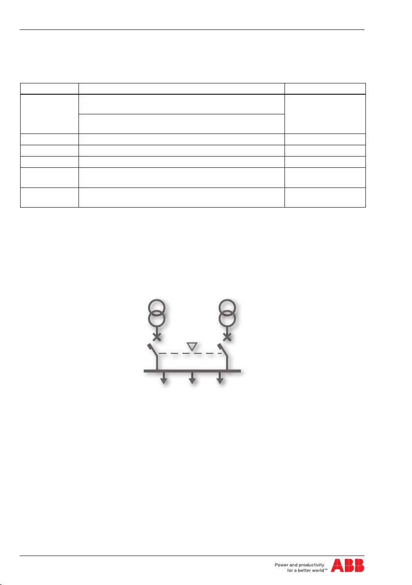
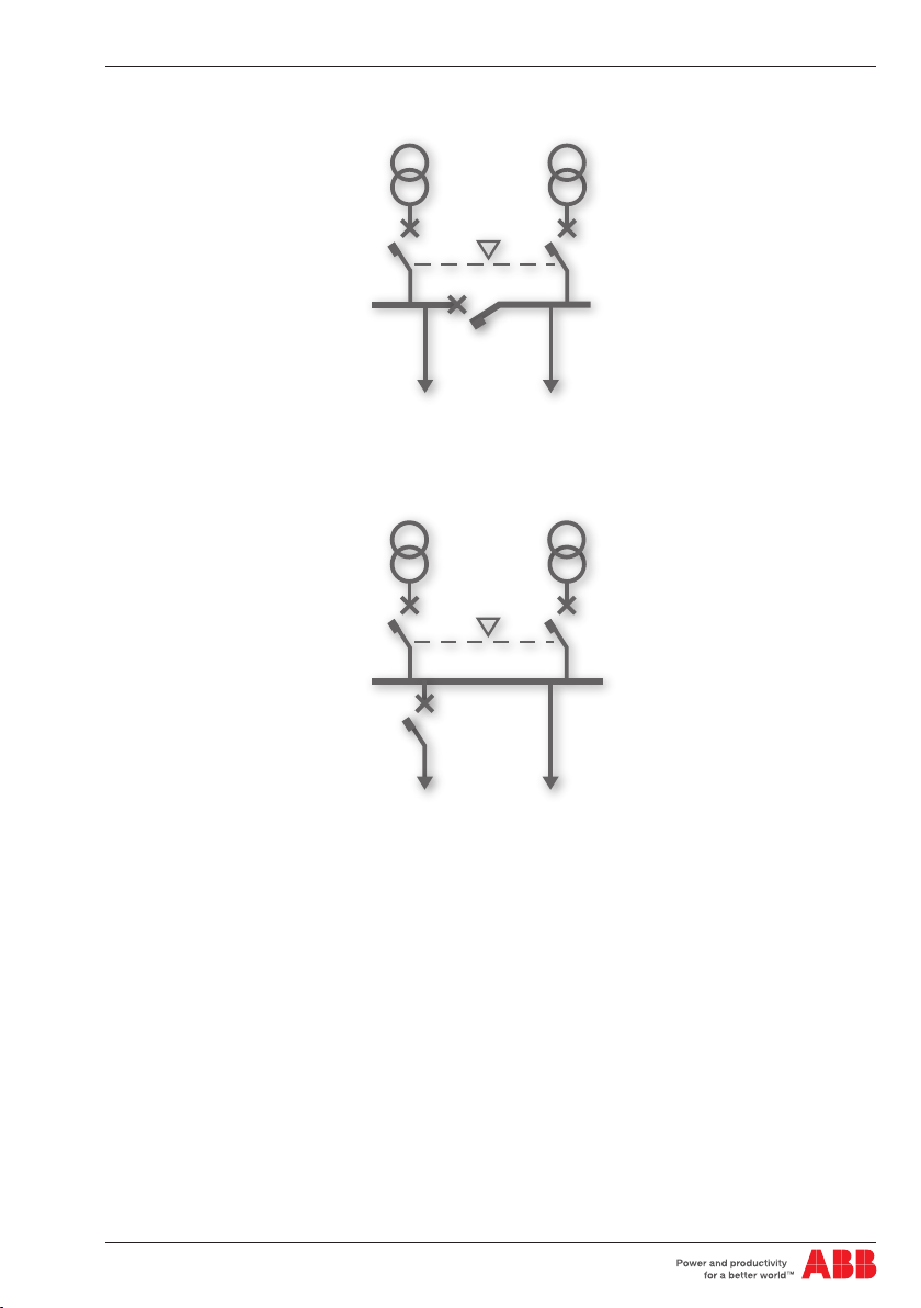
4.1 Switching Main Line – Emergency Line (2CBs)
Description
Both lines are normally present; in cause of anomaly on the main line,
ATS022 switches to the emergency line used as the reserve line.
mains (Generator is not in use)
Generator start delay after detection of a fault in the mains
(Generator in use).
Opening and closing delay of CB3 if used in Bus Tie
application.
0…30s
0…60s
KA00428
Figure 4.1: 2CBs application layout – generator not in use
1SDH000760R0002
8
Page 9
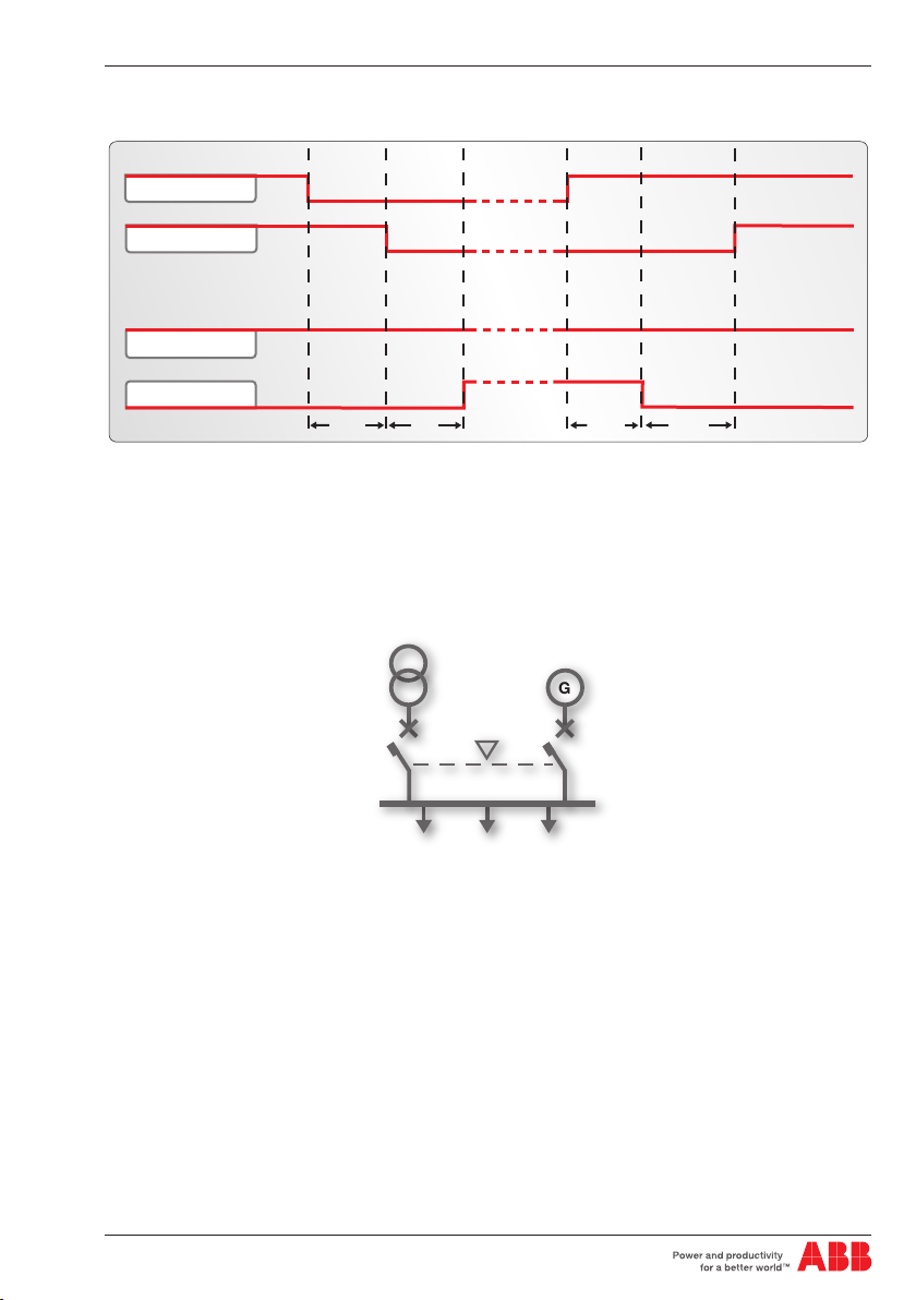
4. Applications of device ATS022
Installation and operating instructions, ATS022
Time diagrams
Line 1 ok
CB1 CLOSED
Line 2 ok
CB2 CLOSED
TS
TCE
TBS
TCN
Figure 4.2: 2CBs application time diagram - main line LN1
4.2 Switching Main Line – Emergency generator (2CBs)
Description
In case of main line failure ATS022 automatically starts up an emergency generator and, as soon as
power on the generator side is available, ATS022 starts the automatic switching procedure.
KA00427
Figure 4.3: 2CBs application layout – generator in use
1SDH000760R0002
9
G
Page 10
Installation and operating instructions, ATS022
4. Applications of device ATS022
Time diagrams
Line 1 ok
CB1 CLOSED
Gen start
Line 2 ok
CB2 CLOSED
TS TCE TCNTBS TGOFF
Figure 4.4: 2CBs application time diagram - generator in use
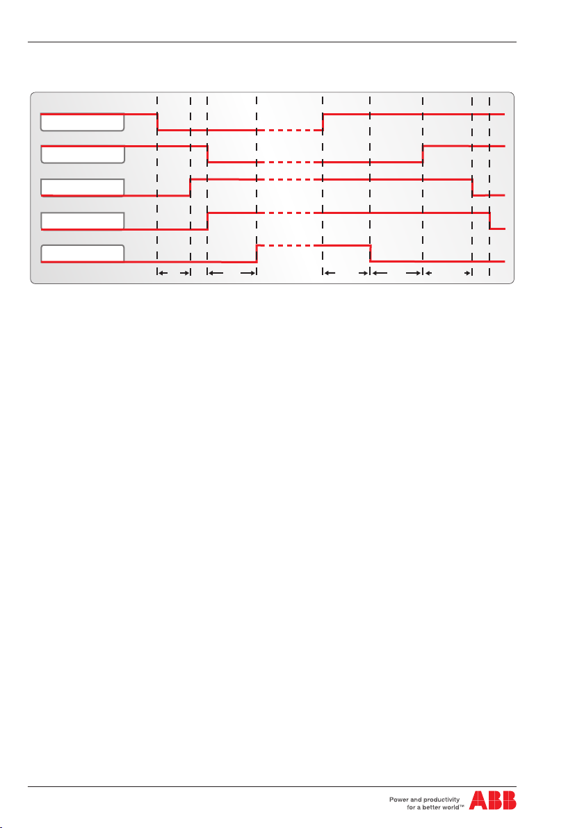
4.3 Non priority loads control (NPL)
Description
In case of main line failure the ATS022 starts the switching procedure and controls the non priority loads
by opening closing circuit breaker CB3.
ATS022 acquires the CB3 open/close status from the dedicated input DI11 and commands the opening
and closing by activating output DO11.
The application of non priority loads requires the use of two CT-AWE typed timed relays for operating the
opening and closing of CB3.
Two configurations are possible for utilisation depending on the position of circuit breaker CB3:
• CB3 in Bus Tie position (3CBs NPL – BUS TIE)
• CB3 on starting line (3CBs NPL).
It is possible to select from two options from the menu on the display:
• only disconnection of non priority loads by opening CB3 (manual re-closure). In this case timed relays
CT-AWE are not necessary
• disconnection and re-connection of non priority loads by opening and closing of CB3
For more details refer to the wiring diagrams of the product.
1SDH000760R0002
10
Page 11
4. Applications of device ATS022
Installation and operating instructions, ATS022
CB1
CB3
NPL
Figure 4.5: Application layout 3CBs NPL BUSTIE
CB1
CB3
NPL
Figure 4.6: Application layout 3CBs NPL
CB2
CB2
1SDH000760R0002
11
Page 12
Installation and operating instructions, ATS022
4. Applications of device ATS022
Time diagrams
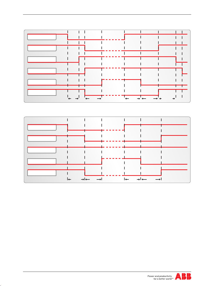
Line 1 ok
CB1 CLOSED
Gen start
Line 2 ok
CB2 CLOSED
CB3 CLOSED
TS
TCE
TBS
Figure 4.7: Application time diagram 3CBs NPL BUS TIE - generator in use
Line 1 ok
CB1 CLOSED
TCN
TGOFF
Line 2 ok
CB2 CLOSED
CB3 CLOSED
TS TCE TCNTBS
Figure 4.8: Application time diagram 3CBs NPL BUS TIE - generator not in use - main line LN1
1SDH000760R0002
12
Page 13
4. Applications of device ATS022
Line 1 ok
CB1 CLOSED
Gen start
Line 2 ok
CB2 CLOSED
CB3 CLOSED
TS TCE TCNTBS
Installation and operating instructions, ATS022
Figure 4.9: Application time diagram 3CBs NPL- generator in use
Line 1 ok
CB1 CLOSED
TGOFF
Line 2 ok
CB2 CLOSED
CB3 CLOSED
TS TCNTBS
TCE
Figure 4.10: Application time diagram 3CBs NPL - generator not in use - main line LN1
1SDH000760R0002
13
Page 14

Installation and operating instructions, ATS022
4. Applications of device ATS022
4.4 Control of two independent power supply lines
separated by Tie (3CBs Bus Tie)
Description
Lines LN1 and LN2 supply two different sections of the plant separated by a bus tie circuit breaker CB3,
normally open.
In case of failure of one of the two supply lines, ATS022 closes CB3; the available line thus powers both
the sections downline. When the line is restored ATS022 restores the normal plant conditions by opening
CB3.
ATS022 acquires the open/close status of the device by means of dedicated input DI11 and commands
the opening and closing by activating output DO11.
The Bus Tie application requires the use of two CT-AWE type timed relays for operating the opening and
closing of CB3.
The three circuit breakers CB1 – CB2 – CB3 must be interlocked mechanically for reasons of safety
(Emax circuit breakers – C type interlock).
CB1
CB3
Figure 4.11: Application layout 3CBs BUS TIE
Time diagrams
Line 1 ok
CB1 CLOSED
Line 2 ok
CB2 CLOSED
CB3 CLOSED
TS TC TCNTBS
Figure 4.12: Application time diagram 3CBs BUS TIE – line LN1 failure
CB2
1SDH000760R0002
14
Page 15

4. Applications of device ATS022
Line 1 ok
CB1 CLOSED
Line 2 ok
CB2 CLOSED
CB3 CLOSED
TS TC TCNTBS
Installation and operating instructions, ATS022
Figure 4.13: Application time diagram 3CBs BUS TIE – line LN2 failure
4.5 Automatic switching without inverse procedure
Description
Following an anomaly of the main line, ATS022 switches on an emergency line (1). If the mains supply
is restored, the inverse switching procedure is not started up (2). If there is a fault in the reserve line,
ATS022 must open the emergency switch (3) and wait for restoration of the emergency line to reclose (4),
without in any case providing for switching on the main line. This operating mode is also applicable if the
generator is present: in this case, after time Ts the generator is started up and as soon as the emergency
line is available CB1 is opened.
ATTENTION If ATS022 is not powered by the auxiliary supply and by any of the two lines the device
waits for at least one of the two lines (5) to return before proceeding with the switching procedure (6).
The option is not available in case of 3CBs Bus Tie application and in case of selection of the no priority
line option.
Time diagrams
(1) (2) (3) (4) (5) (6)
Line 1 ok
CB1 CLOSED
Line 2 ok
CB2 CLOSED
TS
TCE
TBS TCE
TBS
Figure 4.14: 2CBs application time diagram - generator not in use – without inverse switching
procedure
1SDH000760R0002
15
Page 16

Installation and operating instructions, ATS022
4. Applications of device ATS022
4.6 Line Priority Selection
Description
ATS022 allows selection of the main line by means of the menu on the display. The following selections
are possible:
- main line: Line LN1
- main line: Line LN2 (selection possible only if generator is not in use)
- no line priority: ATS022 ensures power supply to the load from any of the two lines without
considering either of these as priority, therefore, for example, following switching on line LN2 due
to failure of line LN1, ATS022 remains on line LN2 even if LN1 is restored.
Time diagrams
Line 1 ok
CB1 CLOSED
Line 2 ok
CB2 CLOSED
TS TCE TBS TCN
Figure 4.16: Time Diagram no line priority – generator non in use
Line 1 ok
CB1 CLOSED
Gen start
Line 2 ok
CB2 CLOSED
TS TCE
Figure 4.17: Time diagram no line priority – generator in use
1SDH000760R0002
16
Page 17

4. Applications of device ATS022
Installation and operating instructions, ATS022
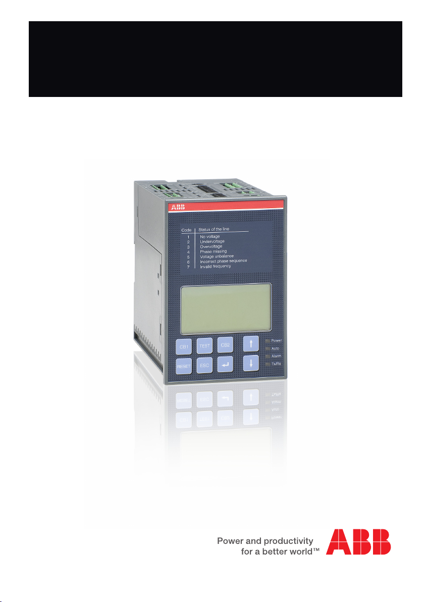
5. Using the automatic transfer switch
5.1 Interface
ATS022
M3010004A
Status of the line
Code
1
No voltage
2
Undervoltage
3
Overvoltage
4
Phase missing
5
Voltage unbalance
6
Incorrect phase sequence
7
Invalid frequency
2
5
1
16
15
14
10
11
RESET
12
13
97 34 86
Figure 5.1: Description of ATS022 front panel interface
Ref. Description
1 CB1: pushbutton for opening/closing circuit breaker CB1
2 CB2: pushbutton for opening/closing circuit breaker CB2
3 CB3: CB3 opening/closure procedure graphic indication (combination of UP-DOWN keys for at
least 2sec)
4 RESET: pushbutton for automatic/manual mode selection and alarms reset
5 TEST: test modes selection pushbutton
6 ENTER: pushbutton for confirming an action
7 ESC: pushbutton for returning to the previous step
8 UP: pushbutton for moving up on the menu
9 DOWN: pushbutton for moving down on the menu
10 LED POWER: indicates presence of power supply
11 LED AUTO: indicates automatic or manual mode
1SDH000760R0002
17
Page 18

Installation and operating instructions, ATS022
Ref. Description
12 LED ALARM: indicates active alarm
13 Tx/Rx LED: indicates bus communication status
14 GRAPHIC DISPLAY
15 PLATE SHOWING LINES STATUS CODES
16 Serial No.
Table 5.1: Description of ATS022 interface
5. Using the automatic transfer switch
5.2 LED indicators
Alarm
The steady red Alarm LED may indicate the switching logic disabled condition or one of the following
events:
• circuit breakers command failed
• protection releases tripped
• removal of circuit breakers
• generator alarm
• logic disabling from input DI3
• both CBs closed
The alarm LED switches Off indicating that the switching logic is enabled and no alarms are present
Auto
The Auto LED indicates the operating mode:
• manual: LED Off
• automatic: steady green LED
• test: flashing green LED
Power
LED Power LED indicates the presence of power supply:
• power supply present: steady green LED indicates power supply from line voltage or from auxiliary
source present
• no power supply: LED Off indicates that both lines are not present and that the Powersave condition
has ended. The switching logic is in stand-by for return of one of the line voltages
• Powersave: green flashing LED indicates, if both lines are absent and if no auxiliary power supply is
present, that the device is active and is in stand-by for return of one of the line voltages (maximum
duration 1 minute). When the Powersave period ends, the LED switches off and the device awaits
a line voltage. The moment the normal or the emergency line is restored, with ATS022 in automatic,
the unit analyses the conditions of the lines monitored and the status of the circuit breakers and
proceeds with the switching operation in accordance with the situation concerned.
TX/RX
The TX/RX LED indicates the bus communication status.
• Communication via bus under way: green LED flashing at variable frequency
• Communication via bus not active: LED Off
1SDH000760R0002
18
Page 19

5. Using the automatic transfer switch
Installation and operating instructions, ATS022
5.3 Keypad keys
CB1 key
In manual mode, press the CB1 key for Opening/Closure of circuit breaker CB1.
CB2 key
In manual mode, press the CB2 key for Opening/Closure of circuit breaker CB2.
RESET
Press RESET to select the Manual or Automatic operating mode.
In case of alarm, press RESET to reset the alarm and the device returns to manual mode. Press RESET
again to bring the device to automatic mode.
TEST key
Press the TEST key to set the test modes of the
direct and inverse switching sequences.
ATS022 must be in the manual position. To exit TEST mode press
RESET.
Enter key
Used for confirming the action or entry to the menu.
ESC key
Used for cancelling an action and returning to previous menu.
UP key
Used for moving up on the menu.
DOWN key
Used for moving down on the menu.
1SDH000760R0002
19
Page 20

Installation and operating instructions, ATS022
5. Using the automatic transfer switch
5.4 Setting the operating modes
5.4.1 Manual mode
To select the Manual operating mode of unit ATS022:
a. Make sure the Power LED is On, see Figure 5.2/1
b. If the Auto LED is OFF, see Figure 5.2/2, the automatic transfer switch is in Manual mode.
c. If the AUTO LED is ON, press RESET, see Figure 5.2/3 . The Auto LED switches to OFF and the
device is in Manual Mode, see Figure 5.2/4 .
1 2
Manual mode
!
OR
2 3 4
CB2
TEST
CB1
KA00345IT
Figure 5.2: Description of manual mode selection procedure for ATS022
5.4.2 Automatic mode
To select the Automatic operating mode of unit ATS022:
a. Make sure the Power LED is On, see Figure 5.3/1
b. Press RESET once, see Figure 5.3/2. If the Auto LED is ON, the automatic transfer switch ATS022 is
in Automatic mode, see Figure 5.3/3
c. If the Auto LED is OFF, press RESET again, see Figure 5.3/3; the Auto LED switches to ON and the
device is in Automatic mode/ Figure 5.3/4
1 2 3
CB2
TEST
CB1
Automatic Mode
!
Manual mode
!
OR
3
KA00347IT
4
CB2
TEST
CB1
Figure 5.3: Description of automatic mode selection procedure for ATS022
1SDH000760R0002
20
5
!
Automatic Mode
Page 21

5. Using the automatic transfer switch
5.5 Graphic Display
1
14
Installation and operating instructions, ATS022
7 2 15 19 10
6 20
LN1
LN2
TBS..
LN1:
0,0
0,0
3
LN2:
0,0
5
Figure 5.4: Description of ATS022 display
Ref. Description
1 LN1: line 1
2 LN2: line 2
3 CB1 status graphic indicator
4 CB2 status graphic indicator
5 CB3 status graphic indicator
6 LN1 power presence icon
7 LN2 power presence icon
8 application type indicator
9 manual mode indicator
10 test mode indicator
11 generator presence indicator
12 generator start (UP arrow)/stop (DOWN arrow) indicator
13 open/close command execution indicator
14 timing indicator
15 LN1 power measurement
16 LN2 power measurement
17 LN1 frequency measurement
18 LN2 frequency measurement
19 LN1 line status code
20 LN2 line status code
21 local/remote mode indicator
Table 5.2: Description of ATS022 display
NPL
8
0,0
4
1613
18
V
Hz
V
Hz
1
GT
G
1
M
L
17
11
12
9
21
1SDH000760R0002
21
Page 22

Installation and operating instructions, ATS022
5. Using the automatic transfer switch
5.5.1 LN1 and LN2 lines status indication
The presence/absence of lines LN1 and LN2 is shown graphically on the display by means of filled/
empty icons, see Figure 5.4/6 – 5.4/7, and a specific status code
If there is an anomaly on the line voltage, the icon concerned is empty and the error code is displayed as
defined by the following Table:
Line status Code
No power 1
Minimum voltage 2
Maximum voltage 3
Phase missing 4
Phase imbalance 5
Inverted sequence 6
Frequency out of range 7
Table 5.3: Description of line status codes ATS022
5.5.2 Browsing through the Menu
Press Enter to access the main Menu. Three different levels of configuration of the unit can be accessed
from the main menu:
Figure 5.5: Description of main menu ATS022
Access to the configuration pages requires a 4-digit password which must be entered using the UP,
DOWN and ENTER keys.
The password is valid for one minute after the last pressing of a key.
For the first access to the system the password is 0001; subsequently change the password as desired.
If the password is lost or forgotten, contact the service centre.
1SDH000760R0002
22
Page 23

5. Using the automatic transfer switch
Installation and operating instructions, ATS022
Configuration of the System
The system configuration section makes it possible to set:
- The parameters of the two lines
Parameters of lines LN1 - LN2 Value Factory settings
100V/57V– 115V/66V - 120V/70V - 208V/120V
- 220V/127V - 230V/132V -
Rated voltage
Rated frequency 50Hz - 60 Hz, 16 2/3 Hz, 400 Hz 50Hz
Number of phases LN1 1 phase / 3 phases with N / 3 phases without N 3 phases with N
Number of phases LN2 1 phase / 3 phases with N / 3 phases without N 3 phases with N
Presence of external voltage
transformer
Primary voltage TV
Secondary voltage TV
240V/138V - 277V/160V - 347V/200V 380V/220V - 400V/230V - 415V/240V 440V/254V - 480V/277V
absent/present
(for voltages greater than 480VAC)
100V/57V– 115V/66V - 120V/70V - 208V/120V
- 220V/127V - 230V/132V 240V/138V - 277V/160V - 347V/200V 380V/220V - 400V/230V - 415V/240V 440V/254V - 480V/277V - 500V/288V 550V/317V - 600V/347V - 660V/380V 690V/400V - 910V/525V - 950V/550V 1000V/577V - 1150V/660V
100V/57V– 115V/66V - 120V/70V - 208V/120V
- 220V/127V - 230V/132V 240V/138V - 277V/160V - 347V/200V 380V/220V - 400V/230V - 415V/240V 440V/254V - 480V/277V
400V/230V
absent
690V/400 V
400V/230 V
Table 5.4: Description of parameters of lines ATS022
- Type of application
Type of application Value Factory settings
Protection devices
2CBs / 3CBs NPL opening only / 3CBs NPL
opening&closing / 3CBs NPL BusTie / 3CBs Bus Tie
2CBs
Utilisation of generator Generator not in use / Generator in use Generator not in use
Priority Line Line LN1 / Line LN2 / No priority Line Line LN1
Switching With inverse procedure/Without inverse procedure With inverse procedure
Table 5.5: Description of types of application ATS022
Device configuration
The device configuration section makes it possible to set:
- Limit thresholds
Limit thresholds Value Factory settings
Min/max voltage
threshold
Min/max frequency
threshold
-30% …-5%, +5% … +30%, step ± 1%
(Imbalance of voltage set at same threshold)
-15%; +15%
-10% …-1%, +1% … +10%, step ± 1% -1%; +1%
Table 5.6: Description of limit thresholds ATS022
1SDH000760R0002
23
Page 24

Installation and operating instructions, ATS022
5. Using the automatic transfer switch
- Time delays
Time delays Value Factory settings
TS Delay 0…30s, step 1s 0s
TBS Delay 0…59s, , step 1s, 1,2,3…30min, step 1min 0s
TCE Delay 0…60s, step 1s 3s
TCN Delay 0…60s, step 1s 3s
TC Delay 0…60s, step 1s 3s
TGOFF Delay 0…59s, , step 1s, 1,2,3…30min, step 1min 5s
Table 5.7: Description of time delays ATS022
- Digital inputs
Digital Input Value Factory settings
Digital Input DI10 - function
Digital Input DI10 - type NO/NC NO
Digital Input DI8 - type NO/NC NO
Table 5.8: Description of inputs ATS022
disabled/generator start/logic enabling/remote
reset/EMERGENCY BLOCK
Generator Start
- Modbus parameters
Modbus Value Factory settings
Modbus Address 1…247 1
Modbus Baud Rate 9600/19200/38400 bps 9600
Modbus Stop Bits 0,1 1
Modbus Parity even, odd, absent absent
mode local, remote local
Table 5.9: Description of Modbus parameters ATS022
- Language and backlit display
Function Value Factory settings
Backlighting duration Always On, 0…59s, step 1s, 1,2,3…30min, step 1min Always On
Language
Table 5.10: Description of language and backlighting ATS022
English/Italian/German/French/Spanish/Finnish/
Russian/Chinese
English
1SDH000760R0002
24
Page 25

5. Using the automatic transfer switch
Diagnostics
The diagnostics section makes it possible to access the following pages:
Values Measured: the voltage and frequency values measured on lines LN1 and LN2 can be consulted
on the display.
Alarms Log: the latest alarms/events are displayed, up to a maximum of 20. The number of alarms is
shown at the top of the page and the latest alarm is always at the top of the list. The log is cleared by
selecting Clear Log and pressing Enter.
Installation and operating instructions, ATS022
Diagnostics
2/2
Measured Values
Alarm Log
SW: 1A
KA00477
Figure 5.5: Description of diagnostics menu ATS022
Figure 5.6: diagnostics – values measured page ATS022
Figure 5.7: diagnostics – Alarms Log page ATS022
SN: 12345678
1SDH000760R0002
25
Page 26

Installation and operating instructions, ATS022
5. Using the automatic transfer switch
5.6 Using pushbuttons in manual mode
Opening/Closing circuit breakers CB1, CB2
In manual mode the circuit breakers can be controlled by means of pushbuttons CB1 and CB2. In case
of a fault, the alarms are activated by the same methods as those for the automatic switching sequence.
Pressing the CB1 key:
• If CB1 is closed, the opening command is sent to CB1
• If CB1 and CB2 are both open, the closing command is sent to CB1
• If CB1 is open and CB2 is closed, no operation is carried out
Pressing CB2 key:
• If CB2 is closed, the opening command is sent to CB2
• If CB2 and CB1 are both open, the closing command is sent to CB2
• If CB2 is open and CB1 is closed, no operation is carried out
Opening/Closing circuit breaker CB3
In manual mode, combination of the UP and DOWN keys allows Opening/Closing of circuit breaker CB3.
• CB3 opening: press the UP and DOWN keys simultaneously for at least 2 seconds.
• CB3 closing: press the UP and DOWN keys simultaneously for at least 2 seconds.
Manual Start/Stop of generator
In manual mode, the combination of the RESET, CB1 and CB2 keys allows Start/Stop of the generator.
• Generator Start: keeping RESET pressed, press CB1
• Generator Stop: keeping RESET pressed, press CB2
5.7 Test Modes
ATS022 makes it possible to select two different test modes:
• testing the entire switching procedure (complete Test)
• generator start/stop test (gen set test)
WARNING: when the test procedure ends, the user must make sure the device is not left accidentally in
TEST mode
Complete Test
With ATS022 in manual mode, press TEST: all the LEDs, except Tx/Rx, flash twice simultaneously and
then the Auto LED Auto flashes every 0.5 sec.; the graphic display shows the icon T.
The test procedure varies according to the application selected:
1SDH000760R0002
26
Page 27

5. Using the automatic transfer switch
2 CBs 3CBs NPL
1. Press TEST; start generator
(not performed if generator is NOT in use)
2. Press TEST; CB1 Opening
4. Press TEST; CB2 Closure
5. Press TEST; CB2 Opening
6. Press TEST; CB1 Closure
8. Press TEST; stop generator
(not performed if generator is NOT in use)
3CBs NPL Bus Tie 3CBs Bus Tie
1. Press TEST; start generator
(not performed if generator is NOT in use)
2. Press TEST; CB1 Opening
3. Press TEST; CB3 Opening
4. Press TEST; CB2 Closure
5. Press TEST; CB2 Opening
6. Press TEST; CB3 Closure
7. Press TEST; CB1 Closure
8. Press TEST; stop generator
(not performed if generator is NOT in use)
Table 5.11: Description of complete TEST mode ATS022
At the end of the procedure, press TEST again to resume the sequence.
Alarms, if any, on the protection devices control are activated in the same manner as the automatic and
manual operating modes.
The user can stop the TEST sequence by pressing the RESET.
1. Press TEST; start generator
(not performed if generator is NOT in use)
2. Press TEST; CB1 Opening
3. Press TEST; CB3 Opening
4. Press TEST; CB2 Closure
5. Press TEST; CB2 Opening
6. Press TEST; CB1 Closure
7. Press TEST; CB3 Closure
(not performed if ATS022 has activated the
DISCONNECTION ONLY function)
8. Press TEST; stop generator
(not performed if generator is NOT in use)
1. Press TEST; CB1 Opening
2. Press TEST; CB3 Closure
3. Press TEST; CB3 Opening
4. Press TEST; CB1 Closure
5. Press TEST; CB2 Opening
6. Press TEST; CB3 Closure
7. Press TEST; CB3 Opening
8. Press TEST; CB2 Closure
Installation and operating instructions, ATS022
Gen Set Test
This test mode makes it possible to test only the generator start and stop with the plant running without
opreating the circuit breakers on the line in any manner whatsoever, only if the ATS022 is set with the
generator in use, otherwise the Gen Set Test is not performed.
1SDH000760R0002
27
Page 28

Installation and operating instructions, ATS022
With ATS022 in manual mode, keep the TEST key pressed for at least 3 seconds, on releasing the TEST
key, all the LEDs, except Tx/Rx, flash simultaneously four times and then the Auto LED flashes at 0.5Hz;
the graphic display shows the GT icon.
The test procedure is as follows:
1. Press TEST; start generator
2. Press TEST; stop generator
Table 5.12: Description of test method GEN SET ATS022
5. Using the automatic transfer switch
1SDH000760R0002
28
Page 29

6. Input and output signals
Installation and operating instructions, ATS022
6. Input and output signals
6.1 Output signals (DO1…DO12)
DO1, DO2, DO3, DO4: Circuit breakers open/close command
Output signals DO1, DO2, D03, DO4 control the opening and closure of circuit breakers CB1 and CB2
connected to ATS022.
The control logic integrated in the device punctually checks the correct operation of the circuit breakers
following the command.
If the change in status of the circuit breaker is not received within 5 seconds of sending the command,
the device considers the command as failed and operates as below:
• alarm LED lights up.
• DO6 alarm output activation
• DO9 alarm output activation
The alarm relative to the failed operation is recorded in the section concerned of the "Alarms Log".
To reset the alarm press RESET:
the alarm is reset and ATS022 goes into manual mode.
Press RESET again to bring ATS022 to automatic mode.
DO5 Emergency generator start/stop command
Start and stop of the Emergency generator are controlled by means of a bistable relay, making it possible
to maintain the generator start command even when the powersave mode runs out.
• contact DO5 (X23:1 ; X23:2 - NO):
- stop unit = contact open
- start unit = contact closed
• contact DO5 (X23:2 ; X23:3 - NC):
- stop unit = contact closed
- start unit = contact open
DO6 Alarm signal
When an alarm is generated, contact DO6 switches, the switching logic is disabled and the alarm LED
lights up.
To reset the alarm press RESET:
the alarm is reset, the Alarm LED turns Off and the ATS022 enters manual mode.
Press RESET again to bring ATS022 to automatic mode.
DO7-DO8 Not available
DO9 Circuit breaker operation failed alarm indication
When the opening or closing command of a circuit breaker fails, contact DO9 closes; the switching logic
is disabled and the Alarm LED lights up.
To reset the alarm press RESET:
the alarm is reset, the Alarm LED turns Off and the ATS022 enters manual mode.
Press RESET again to bring ATS022 to automatic mode.
DO10 Automatic/Manual mode indication
Contact DO10 indicates the operating mode of the device:
• DO10 open: ATS022 operates in automatic mode
• DO10 closed: ATS022 operates in manual mode
DO11 CB3 circuit breaker control
Depending on the operating mode set, contact DO11 allows control of only opening or opening/closing
of circuit breaker CB3:
Protection Devices selection DO11 NOTES
2 CBs not used
1SDH000760R0002
29
Page 30

Installation and operating instructions, ATS022
6. Input and output signals
3CBs NPL used
3CBs NPL Bus Tie used CT-AWE* type timed relays required
3CBs Bus Tie used CT-AWE* type timed relays required
*The CT-AWE must be adjusted with a time between 200ms and 300ms.
Table 6.1: Description of DO11 functions - ATS022
CT-AWE type timed relays required if
selected opening&closing option
DO12 Logic enabled/disabled indication
Contact DO12 indicates whether switching logic is enabled or disabled:
• DO12 open: logic enabled
• DO12 closed: logic disabled
6.2 Input signals
DI1, DI2 Status signals of circuit breakers CB1, CB2
Inputs DI1, DI2 must be connected to auxiliary contacts of the status of the circuit breakers of the normal
and emergency lines
• DI1, DI2 open: CB open
• DI1, DI2 closed: CB closed
DI3 Switching Logic Activation/Deactivation
Input DI3 is used for enabling/disabling the switching logic. The function may be used for integrating
generic alarms coming from the plant the presence of which leads to disabling of ATS022 automatic
switching logic.
• DI3 open: logic disabled
• DI3 closed: logic enabled
DI4, DI5 Circuit breakers activation indication
The auxiliary opening contacts of the normal and emergency lines must be connected to contacts DI4,
DI5 for activation of the trip.
• DI4, DI5 open: CB tripped
• DI4, DI5 closed: CB not tripped
In case of trip of a circuit breaker (CB1 or CB2):
• the trip indication contact opens
• the switching logic is disabled
• Alartm contact DO6 is closed
• contact DO12 is closed
• the Alarm LED lights up
• the Auto LED switches Off
To reset the TRIP indication press RESET.
• The TRIP indication is reset
• Alarm LED switches Off
• ATS022 operates in manual mode
• contact DO10 is closed
Press RESET again to bring ATS022 to Automatic mode
• contact DO10 is opened
• the Auto LED lights up
DI6, DI7 Circuit breakers CB1, CB2 removed/inserted position indication
The auxiliary position contacts of the circuit breakers of the normal and emergency lines must be
1SDH000760R0002
30
Page 31

6. Input and output signals
connected to inputs DI6 and DI7 in removable execution.
• DI6, DI7 open: CB removed
• DI6, DI7 closed: CB inserted
If the circuit breaker is removed:
• the position indication contact opens
• the switching logic is disabled
• Alartm contact DO6 is closed
• contact DO12 is closed
• the Alarm LED lights up
• the Auto LED switches Off
When the circuit breaker is inserted:
• the position indication contact closes
• the switching logic is re-enabled
• Alarm LED switches Off
• ATS022 operates in manual mode
• contact DO10 is closed
• Alarm contact DO6 is opened
• contact DO12 is opened
• the Auto LED switches Off
To set the device in automatic mode press RESET
• contact DO10 is Opened
• the Auto LED lights up
Installation and operating instructions, ATS022
DI8 Generator Alarm
Input DI8 is used for connecting various alarms coming from the emergency generator: drop in oil
pressure, Over Temperature, etc.
Input DI8 may be set as normally open (NO) or normally closed (NC) by means of the menu on the
graphic display.
In case of an active generator alarm
• the switching logic is disabled
• Alartm contact DO6 is closed
• contact DO12 is closed
• the Alarm LED lights up
• the Auto LED switches Off
• contact DO10 is closed
• the display shows "generator alarm"
When the DI8 signal is deactivated:
• Alarm LED switches Off
• Alarm contact DO6 is opened
• contact DO12 is opened
• ATS022 operates in manual mode
• the "generator alarm" message disappears from the display
To set the device in automatic mode press RESET
• contact DO10 is Opened
• the Auto LED lights up
DI9 Forced switching on emergency power supply line
In certain industrial processes, supply of power from the emergency generator may be required instead
of from the normal power supply line, for brief moments, in order to avoid possible operating anomalies
of the supply and ensure high levels of reliability.
1SDH000760R0002
31
Page 32

Installation and operating instructions, ATS022
In automatic mode, by activating input DI9 the forced switching procedure is started up on the
emergency line:
• Generator Start
• opening of circuit breaker on normal line
• closure of circuit breaker on emergency line
The power supply from the emergency line persists as long as the command remains active. When the
command is deactivated, the unit proceeds with the switching procedure on the normal line.
6. Input and output signals
2 CBs:
If DI9 is closed:
• Generator Start
• Opening of circuit breaker CB1
• closure of circuit breaker CB2
If DI9 is open:
• opening of circuit breaker CB2
• closure of circuit breaker CB1
• generator stop
3CBs NPL:
If DI9 is closed:
• Generator Start
• Opening of circuit breakers CB1 and CB3
• closure of circuit breaker CB2
If DI9 is open:
• opening of circuit breaker CB2
• closure of circuit breakers CB1 and CB3
• generator stop
3CBs NPL BUS TIE:
If DI9 is closed:
• Generator Start
• Opening of circuit breakers CB1 and CB3
• closure of circuit breaker CB2
1SDH000760R0002
32
Page 33

6. Input and output signals
Installation and operating instructions, ATS022
If DI9 is open:
• opening of circuit breaker CB2
• closure of circuit breakers CB3 and CB1
• generator stop
DI10 Programmable input
The function associated with input DI10 can be selected from the menu on the display, from among the
following options:
• forced generator start: this function makes it possible to test the correct switching ON/OFF of the
generator with the plant running
Contact type set Description of function
NC Open =gen start; Closed = gen stop
NO Closed =gen start; Open = gen stop
• Enabling automatic switching logic: this function makes it possible to inhibit the automatic
switching logic of the device following an alarm present in the field.
The logic can, however, be disabled if one of the conditions involving the disabling exist
Contact type set Description of function
NC
NO
Closed = switching enabled;
Open switching disabled
Open = switching enabled;
Closed switching disabled
• Reset from Remote: this function allows reset of the device logic in remote by means of remote
actuator.
Contact type set Description of function
NC
NO
Closed = remote reset not active;
Open = remote reset active
Closed = remote reset active;
Open = remote reset not active
• Emergency Block: this function allows prior opening of both circuit breakers of the power supply
and emergency lines and permanent disabling of the switching logic. This function can be used, for
example, in case of an alarm coming from a fire-fighting system which requires immediate opening of
the circuit breakers and disabling of the switching logic.
Contact type set Description of function
NC
NO
Closed = emergency block not active;
Open = emergency block active
Closed = emergency block active;
Open = emergency block not active
Input DI10 may be set as normally open (NO) or normally closed (NC) by means of the menu on the
graphic display.
DI11 CB3 circuit breaker status signal
Input DI11 is connected to the CB3 circuit breaker status auxiliary contacts.
• DI11 open: CB open
• DI11 closed: CB closed
Uscita per controllo CB1
Output to control CB1
Salida para control CB1
Sortie pour controle CB1
Ausgang zur steuerung CB1
Uscita per controllo CB2
Output to control CB2
Salida para control CB2
Sortie pour controle CB2
Ausgang zur steuerung CB2
1SDH000760R0002
Linea 1
Line 1
Linea 1
Ligne 1
Leitung 1
ATS022
33
Linea 2
Line 2
Linea 2
Ligne 2
Leitung 2
Uscita per controllo Gen Start/Stop
Output to control Gen Start/Stop
Salida para control Gen Start/Stop
Sortie pour controle Gen Start/Stop
Ausgang zur steuerung Gen Start/Stop
Uscita per controllo CB3
Output to control CB3
Salida para control CB3
Sortie pour controle CB3
Ausgang zur steuerung CB3
Page 34

Installation and operating instructions, ATS022
Figure 6.1: Control circuit diagram ATS022
Connectors Description DI/DO Type
X11:1 Normal Line LN1: L1 - -
X11:2 Normal Line LN1: L2 - -
X11:3 Normal Line LN1: L3 - -
X11:4 Normal Line LN1: N - -
X12:1 Emergency Line LN2: L1 - -
X12:2 Emergency Line LN2: L2 - -
X12:3 Emergency Line LN2: L3 - -
X12:4 Emergency Line LN2: N - -
X41:1 + Auxiliary power supply - -
X41:2 - Auxiliary power supply - -
X21:1 Com - -
X21:2 CB1 opening command DO1 NO
X21:3 CB1 closure command DO2 NO
X22:1 Com - -
X22:2 CB2 opening command DO3 NO
X22:3 CB2 closure command DO4 NO
X23:1 generator start/stop command D05 Open =gen stop; Closed = gen start
X23:2 Com - -
X23:3 generator start/stop command D05 Closed =gen stop; Open = gen start
X24:1 CB3 opening command D011 NO
X24:2 Com - -
X24:3 CB3 closure command D011 NC
X29:1 ATS022 unit alarm indication DO6
X29.2 not used DO7 -
X29:3 not used DO8 -
X29:4
X29.5 automatic/manual mode indication DO10
X29:6 logic enabled/disabled indication DO12
X29:7 Com - -
X31:1 logic enabling input DI3
X31:2 CB1 status input DI1 0=CB open; I=CB closed
X31:3 CB2 status input DI2 0=CB open; I=CB closed
X31:4 Com - -
X32:1 CB3 status input DI11 0=CB open; I=CB closed
X32.2 programmable input DI10 NO/NC
circuit breakers command alarm
indication
6. Input and output signals
Open = no alarm;
Closed = alarm
DO9
Open = no alarm;
Closed = alarm
Open = Automatic;
Closed = Manual
Open = logic enabled;
Closed = logic disabled
Open = logic disabled;
Closed = logic enabled
1SDH000760R0002
34
Page 35

6. Input and output signals
Connectors Description DI/DO Type
X32:3 switching forcing input DI9 NO
X32:4 generator alarm input DI8 NO/NC
X32.5 CB1 position input DI7 0=CB removed; I=CB inserted
X32:6 CB2 position input DI6 0=CB removed; I=CB inserted
X32:7 CB1 trip input DI5 0=no CB trip; I=CB trip
X32:8 CB2 trip input DI4 0=no CB trip; I=CB trip
X32.9 Com - -
X51:1 Modbus DATA B - -
X51:2 Modbus DATA A - -
X52:3 Modbus GND - -
X61 Earth connection - -
Table 6.2: Description of function and type connector ATS022
Installation and operating instructions, ATS022
1SDH000760R0002
35
Page 36

Installation and operating instructions, ATS022
7. Technical data
7. Technical data
ATS022 Value
Three-phase voltage used
Connected voltage 100Vac - 480Vac (+/-20%)
Phase voltage 57,7Vac - 277Vac (+/-20%)
Safety auxiliary voltage 24Vdc - 110 Vdc (-10% / +15%)
Frequency 50-60-400-16 2/3 Hz
Single-phase voltage used
Phase voltage
57,7Vac - 277Vac (+/-20%)
Safety auxiliary voltage 24Vdc - 110 Vdc (-10% / +15%)
Frequency 50-60-400-16 2/3 Hz
Measurement precision
Voltage 1%
Frequency 1%
Relay utilization category 8 A, AC1, 250 V
Relay/connectors utilization category 6 A, AC1, 250 V
Over voltage category III, Uimp 6 kV
Power consumption Max 12W
IP rating IP20
Device weight 1314g
Operating temperature -20 / +60 °C
(4
Storage temperature -25 / +80°C
Humidity r.h=95% T=25…60°C
Altitude Max. 2000m
NOTES
(1 In single-phase system it is not possible to select Un 100 V, 115 V, 120 V.
(2 In single-phase system, if Un is between 57.7 - 109 V an auxiliary safety power supply is necessary
(3 In case of rated frequency 16 2/3 Hz, an auxiliary safety power supply must be used. If the rated
voltage is greater than 100 VAC external transformers must be used.
(4 If the ATS022 is used in environments with extremely low temperatures (less than - 10°C) it is
advisable to use a safety auxiliary power supply to avoid display problems of the graphic display.
Table 7.1: Technical data ATS022
(1
(2
(3
1SDH000760R0002
36
Page 37

8. Installation of device ATS022
Installation and operating instructions, ATS022
8. Installation of device ATS022
The automatic transfer switch ATS022 can be mounted on the front of the panel door or on DIN rail.
8.1. Door-mounted Automatic Transfer Switch ATS022
The Automatic Transfer Switch ATS022 can be door-mounted as shown in Figure 8.1.
2
1
160
139
91
KA00379
Figure 8.1: Door-mounted ATS022
1SDH000760R0002
2a
2b
37
Page 38

Installation and operating instructions, ATS022
8. Installation of device ATS022
8.2. DIN rail-mounted Automatic Transfer Switch ATS022
The automatic transfer switch ATS022 can be mounted on a 35mm DIN rail as shown in Figure 8.2.
1
KA00500
KA00377
Togliere
3
35mm
EN 50022
2
145
97
3
KA00484IT
1 2
Figure 8.2: DIN rail-mounted ATS022
1SDH000760R0002
38
Page 39

9. Regulatory standards
Installation and operating instructions, ATS022
9. Regulatory standards
ATS022 conforms to the following regulatory standards:
• European Directive 73/23 “LVD – Low Voltage Directive”
• EN 50178 electronic equipment for use in power Installations
• EN-IEC 62103 electronic equipment for use in power Installations
• EN-IEC 60947-5-1 low voltage switchgear and control gear: control circuit devices and switching
elements
• Electromagnetic compatibility EN 50081-2, EN 50082-2
• Environmental conditions IEC 68-2-1, IEC 68-2-2, and IEC 68-2-3
• EN-IEC 61000-4-2: Electromagnetic compatibility (EMC) - Part 4: Testing and measurement
techniques Section 2: Electrostatic discharge immunity test Basic EMC Publication (IEC 61000-4-2
[8KV air, 4KV cont])
• EN-IEC 61000-4-3, Electromagnetic compatibility (EMC) - Part 4: Testing and measurement
techniques Section 3: Radiated, radio-frequency, electromagnetic field immunity test (IEC 61000-4-3
[level 3])
• EN-IEC 61000-4-4, Electromagnetic compatibility (EMC) - Part 4: Testing and measurement
techniques Section 4: Electrical fast transient/burst immunity test Basic EMC Publication (IEC 610004-4 [level 2/3])
• EN-IEC 61000-4-5, Electromagnetic compatibility (EMC) - Part 4: Testing and measurement
techniques Section 5: Surge immunity test (IEC 61000-4-5 [level 1/2])
• EN-IEC 61000-4-6: Electromagnetic compatibility (EMC) - Part 4: Testing and measurement
techniques (IEC 61000-4-6 [level 3])
• EN-IEC 61000-4-8: Electromagnetic compatibility (EMC) - Part 4: Testing and measurement
techniques (IEC 61000-4-8 [level 5])
• EN 50093, Electromagnetic compatibility (EMC) - Part 4: Testing and measurement techniques
Section 11: Voltage dips, short interruptions and voltage variations immunity test (IEC 61000-4-11,
[100ms/5s] B, C criterion)
• CISPR11 (30MHz...1GHz): Emission (Generic Standard, Industrial) – Radiated
• CISPR11 (0.15MHz…30MHz): Emission (Generic Standard, Industrial) – Conducted
• CISPR/CEI 1000-6-3: Part 6: Generic standards – Section 3: Emission standard for residential,
commercial and light-industrial environments
• IEC 60068-2-2: Environmental testing. Part 2: Tests. Test B: Dry heat
• IEC 60068-2-6: Environmental testing. Part 2: Tests. Test Fc: vibration (sinusoidal)
• IEC 60068-2-27: Environmental testing. Part 2: Tests. Test Ea and guidance: shock
• IEC 60068-2-30: Environmental testing. Part 2: Tests. Test Db and guidance: Damp heat, cyclic
• IEC 60068-2-1: Environmental testing. Part 2: Tests. Test A: cold (-20 °C ± 3 °C, 16 hours)
1SDH000760R0002
39
Page 40

Installation and operating instructions, ATS022
10. Troubleshooting
The alarms are shown by means of a message on the ATS022 display. The
Alarm messages are shown in the Table below:
Table 10.1: Alarms ATS022
Alarm Fault Action
CB1 opening failed
CB2 opening failed
CB3 Opening failed
CB1 closure failed
CB2 closing failed
CB1 removed circuit breaker CB2 is removed
CB2 removed circuit breaker CB2 is removed
Logic block
External fault
Trip CB1 Circuit breaker CB1 has tripped
Trip CB2 Circuit breaker CB2 has tripped
Generator alarm Generator alarm input DI8 active
Table 10.1: Alarms ATS022
circuit breaker CB1 on normal line
does not open within 5s
circuit breaker CB2 on emergency
line does not open within 5s
circuit breaker CB3 bus-tie does not
open within 5s
circuit breaker CB1 on normal line
does not close within 5s
circuit breaker CB2 on emergency
line does not close within 5s
Enabled/disabled logic input DI3
inactive
Both circuit breakers are closed (DI1
and DI2 active)
the alarm can be reset by means of the
RESET button.
the alarm can be reset by means of the
RESET button.
the alarm can be reset by means of the
RESET button.
the alarm can be reset by means of the
RESET button.
the alarm can be reset by means of the
RESET button.
The logic is blocked and ATS enters manual
mode.
Reset by inserting CB1.
The logic is blocked and ATS enters manual
mode.
Reset by inserting CB2.
The logic is blocked. Reset by activating DI3
Check wiring
The logic is blocked as long as input DI4 is
deactivated
The logic is blocked as long as input DI5 is
deactivated
The logic is blocked as long as input DI8 is
activated
10. Troubleshooting
1SDH000760R0002
40
Page 41

Installation and operating instructions, ATS022
1SDH000760R0002
41
Page 42

Due to possible development of Standards as
well as of materials, the characteristics and
dimensions specified in this Installation and
operating instructions may be considered as
binding only after confirmation by ABB SACE
Division.
© Copyright 2011 ABB. All rights reserved.
For more information please contact:
ABB S.p.A.
ABB SACE Division
Via Baioni, 35
24123 Bergamo - Italy
Phone: +39 035 395 111
Fax: +39 035 395 306 - 433
www.abb.com
 Loading...