

Page 1
SYSTEM VERSION 6.1
ABB Ability™ System 800xA / Advant® OCS
Control Builder A 1.4
Installation
Page 2

Page 3

SYSTEM VERSION 6.1
ABB Ability™ System 800xA / Advant® OCS
Control Builder A 1.4
Installation
Document Number: 3BSE066174R301
Document Revision: A
Release: April 2019
Trace back information Main Publication:
Tool version: 5.2.025
Build date: 2019-04-10 at 09:54:08
Domain: ABBPA
Workspace, version, checked in: Control Builder A, a52, 2019-04-10
Master: ix-388808-Control Builder A 1.4 Installation.xml
Recipe: ix-389038-Control Builder A 1.4 Installation.rcp
PDF stylesheet: ix-315381-PDF-Stylesheet.xml
Customer stylesheet: ix-315380-CustomerStylesheet.xml
Page 4

Notice
This document contains information about one or more ABB products and may include a description of or a reference
to one or more standards that may be generally relevant to the ABB products. The presence of any such description of
a standard or reference to a standard is not a representation that all of the ABB products referenced in this document
support allof the features of the described or referenced standard. In order to determine the specific features supported
by a particular ABB product, the reader should consult the product specifications for the particular ABB product.
ABB may have one or more patents or pending patent applications protecting the intellectual property in the ABB
products described in this document.
The information in this document is subject to change without notice and should not be construed as a commitment
by ABB. ABB assumes no responsibility for any errors that may appear in this document.
Products described or referenced in this document are designed to be connected, and to communicate information and
data via a secure network. It is the sole responsibility of the system/product owner to provide and continuously ensure
a secure connection between the product and the system network and/or any other networks that may be connected.
The system/product owners must establish and maintain appropriate measures, including, but not limited to, the
installation of firewalls, application of authentication measures, encryption of data, installation of antivirus programs,
and so on, to protect the system, its products and networks, against security breaches, unauthorized access, interference,
intrusion, leakage, and/or theft of data or information.
ABB Ltd and its affiliates are not liable for damages and/or losses related to such security breaches, any unauthorized
access, interference, intrusion, leakage and/or theft of data or information.
ABB verifies the function of released products and updates. However system/product owners are ultimately responsible
to ensure that any system update (including but not limited to code changes, configuration file changes, third-party
software updates or patches, hardware change out, and so on) is compatible with the security measures implemented.
The system/product owners must verify that the system and associated products function as expected in the environment
they are deployed.
In no event shall ABB be liable for direct, indirect, special, incidental or consequential damages of any nature or kind
arising from the use of this document, nor shall ABB be liable for incidental or consequential damages arising from use
of any software or hardware described in this document.
This document and parts thereof must not be reproduced or copied without written permission from ABB, and the
contents thereof must not be imparted to a third party nor used for any unauthorized purpose.
The software or hardware described in this document is furnished under a license and may be used, copied, or disclosed
only in accordance with the terms of such license. This product meets the requirements specified in EMC Directive
2014/30/EU and in Low Voltage Directive 2014/35/EU.
Trademarks
All rights to copyrights, registered trademarks, and trademarks reside with their respective owners.
Copyright © 2019 by ABB.
All rights reserved.
Page 5

Table of Contents
Table of Contents
About This User Manual
1 Installation of Control Builder A
7General .............................................................................................................
7User Manual Conventions .................................................................................
7Warning, Caution, Information, and Tip Icons ......................................
8Terminology .......................................................................................................
9Released User Manuals and Release Notes ....................................................
111.1 Installation Procedures ......................................................................................
111.1.1 Recommended PC Performance and Capacity ...................................
111.1.2 Software Requirements ......................................................................
131.1.3 CBA Suite Installation ..........................................................................
141.1.4 800xA Common 3rd Party Install .........................................................
141.1.5 Central Licensing System ....................................................................
161.1.6 Control Builder A Products ..................................................................
191.1.7 Manual Installation ...............................................................................
211.1.8 Additional Displays During On-line Builder Installation ........................
231.1.9 Engineering Board setup .....................................................................
241.2 Server and Client Configuration ........................................................................
251.2.1 Server Configuration - DCOM ..............................................................
311.2.2 Client configuration – Engineering Board Setup ..................................
331.3 PU410 External Engineering Board ..................................................................
331.3.1 Introduction ..........................................................................................
341.3.2 PU410 Specification .............................................................................
371.3.3 Mechanical Installation ........................................................................
45Revision History .....................................................................................................
3BSE066174R301 A 5
Page 6

3BSE066174R301 A 6
Page 7
About This User Manual
General
About This User Manual
General
Any security measures described in this User Manual, for example, for user access,
password security, network security, firewalls, virus protection, etc., represent possible
steps that a user of an 800xA/Advant OCS® System may want to consider based on
a risk assessment for a particular application and installation. This risk assessment,
as well as the proper implementation, configuration, installation, operation,
administration, and maintenance of all relevant security related equipment, software,
and procedures, are the responsibility of the user of the 800xA/Advant OCS® System.
This user manual describes the installation of Control Builder A.
Control Builder A is a configuration tool for AC 100 and AC 400 Series Controllers. Control
Builder A can be installed in a 800xA system or separate from 800xA.
User Manual Conventions
Microsoft Windows conventions are normally used for the standard presentation of
material when entering text, key sequences, prompts, messages, menu items, screen
elements, etc.
Warning, Caution, Information, and Tip Icons
This User Manual includes Warning, Caution, and Information where appropriate to point
out safety related or other important information. It also includes Tip to point out useful
hints to the reader. The corresponding symbols should be interpreted as follows:
Electrical warning icon indicates the presence of a hazard that could result in electrical
shock.
Warning icon indicates the presence of a hazard that could result in personal injury.
Caution icon indicates important information or warning related to the concept
discussed in the text. It might indicate the presence of a hazard that could result in
corruption of software or damage to equipment/property.
3BSE066174R301 A 7
Page 8

About This User Manual
Terminology
Information icon alerts the reader to pertinent facts and conditions.
Tip icon indicates advice on, for example, how to design your project or how to use
a certain function
Although Warning hazards are related to personal injury, and Caution hazards are
associated with equipment or property damage, it should be understood that operation
of damaged equipment could, under certain operational conditions, result in degraded
process performance leading to personal injury or death. Therefore, fully comply with all
Warning and Caution notices.
Terminology
A complete and comprehensive list of terms is included in System 800xA Terminology
and Acronyms (3BSE089190*). The listing includes terms and definitions that apply to
the 800xA System where the usage is different from commonly accepted industry standard
definitions.
DescriptionTerm
AC 100
AC 400
Control Builder A
800xA
3BSE066174R301 A 8
Advant Controller 100 - Advant (Master) family of Controllers: AC 55,
AC 70, AC 80, AC 110 and AC 160.
Advant Controller 100 integration into Process Portal A800xA for AC 100
Advant Controller 400 - Advant (Master) family of Controllers: AC 410
and AC 450.
Advant Controller 400 integration into Process Portal A800xA for Advant Master
Control Builder A is a configuration tool used to configure and program
the Advant Controller 100 and Advant Controller 400.
Product containing functionality for efficient control and
supervision of an automated process. Key functions are
presentation of process graphics, process dialogs and
presentation of alarms and trends.
Control Builder A with all its software productsCBA Suite Installation
Page 9

About This User Manual
Released User Manuals and Release Notes
Released User Manuals and Release Notes
Table: Related Documentation
DescriptionTitle
System 800xA 6.0 Licensing Information
(2PAA111691-600)
Application Builder User’s Guide (3BDS100560*)
Function Chart Builder User’s Guide
(3BDS100595*)
On-line Builder User’s Guide (3BDS100596*)
On-line Builder Reference Manual (3BSE001974*)
Bus Configuration Builder User’s Guide
(3BDS100312*)
PROFIBUS Library Editor User’s Guide
(3BDS100603R201)
AMPL Configuration Advant Controller 100 Series
Reference Manual (3BSE009626R501)
AMPL Configuration Advant Controller 400 Series
Reference Manual (3BSE002417R601)
Source Code Handling User's Guide
(3BSE003838R101)
Control Builder A 1.4 Release Notes
(3BSE080911*)
Provides information about Central Licensing
System (CLS).
This book describes the Application Builder (APB).
This book describes the Function Chart Builder
(FCB).
This book describes the On-line Builder (ONB).
This book describes the functions of On-line
Builder (ONB).
This book describes the Bus Configuration Builder
tool of the Control Builder A product.
This book describes the utility PROFIBUS Library
Editor of Control Builder A
This manual describes the AC 100 engineering
workflow.
This manual describes the AC 400 engineering
workflow.
This manual describes how to use source code
for Function Chart Builder.
This release notes describes new and changed
functions of Control Builder A 1.4
A complete list of all User Manuals and Release Notes applicable to System 800xA is
provided in System 800xA Released User Documents (3BUA000263*).
3BSE066174R301 A 9
Page 10

3BSE066174R301 A 10
Page 11
1 Installation of Control Builder A
1.1 Installation Procedures
1 Installation of Control Builder A
1.1 Installation Procedures
1.1.1 Recommended PC Performance and Capacity
Recommended performance and capacity of the PCs for different node types can be
found through http://www.abb.com/product/us/9AAC171278.aspx.
If PU410 is used, a separate Network interface is required in the personal computer.
1.1.2 Software Requirements
McAfee VirusScan® Enterprise and Symantec Endpoint Protection (SEP) have been
tested and are qualified virus scanners for use with Control Builder A.
The user should make sure that the installation procedure completes without exposing
the computers to malware or malicious network traffic of any sort.
This can only be done by limiting the communication to the system and by performing
separate virus scanning of any portable media or disks before connecting them to the
system nodes during the installation. After completing the system installation and
configuration (post installation) it is recommended to perform a full virus scan of all
computers in the system.
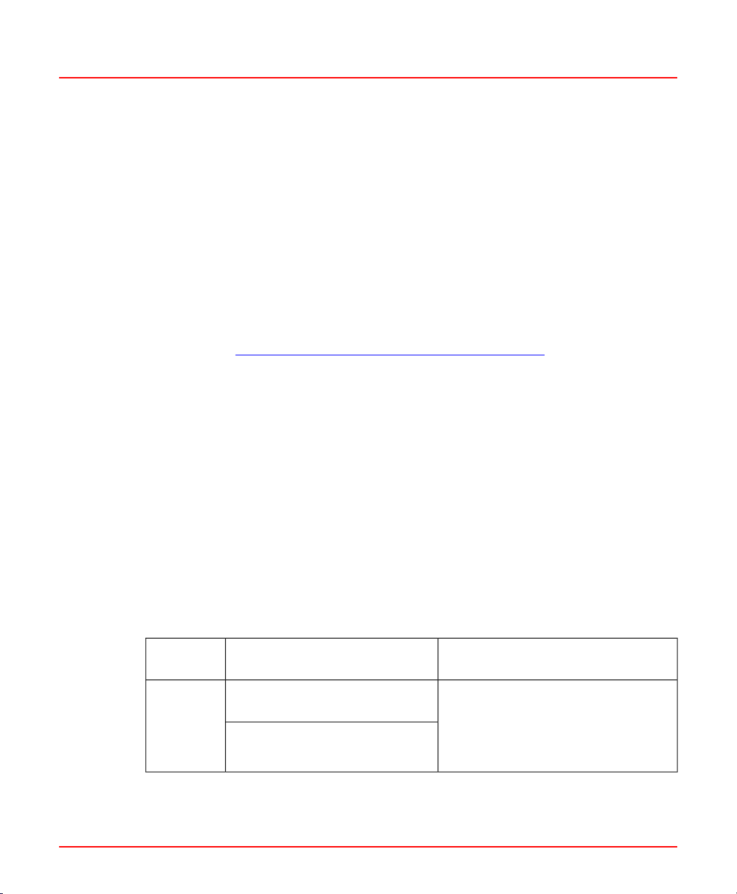
Table 1.1: Server Operating Systems
System
Version
6.1
3BSE066174R301 A 11
Operating System version
Windows Server 2016 LTSB
Standard/Datacenter
Windows Server 2012 R2
Standard/Datacenter Update
1. 64-bit Versions to be used
1
Required Hotfixes and additional
Comments
Server with Desktop Experience. Install
the latest qualified update as per Third
Party Security Updates Validation
Status for System 800xA,
3BSE041902.
Page 12
1 Installation of Control Builder A
1.1 Installation Procedures
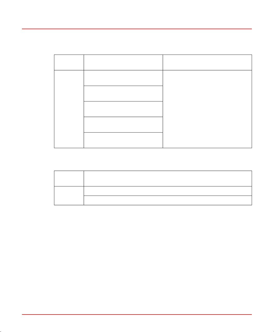
Table 1.2: Client Operating Systems
System
Version
Operating System version
Windows 10 Enterprise 2016
LTSB
Windows 10 IoT Enterprise 2016
LTSB
6.1
Windows 10 Enterprise 2015
LTSB
Windows 10 IoT Enterprise 2015
LTSB
Windows 8.1 Update
Professional/Enterprise
1. 64-bit Versions to be used
Table 1.3: Prerequisite Software
System
Version
Required Software (Included on the CBA Media)
ABB 800xA Common 3rd Party Install
6.1
ABB Central Licensing System (CLS) has to be installed
1
Required Hotfixes and additional
Comments
Install the latest qualified update as
per Third Party Security Updates
Validation Status for System 800xA,
3BSE041902.
3BSE066174R301 A 12
Page 13

1 Installation of Control Builder A
1.1 Installation Procedures
1.1.3 CBA Suite Installation
1. Log on the computer as a user with administrator privileges.
2. Insert the Control Builder A installation media and the Autorun display is seen as
shown in Figure 1.1.
Figure 1.1: Control Builder A autorun display
3BSE066174R301 A 13
Page 14

1 Installation of Control Builder A
1.1 Installation Procedures
3. If the Autorun display does not appear, double click on the autorun.exe located in
the root of the Control Builder A installation media.
4. Click on Release Notes in the upper right of the Autorun display to get information
about Control Builder A.
Click on CBA Suite Installation and the menu as shown in Figure 1.2 appears:
Figure 1.2: Autorun display with CBA Suite Installation selected.
1.1.4 800xA Common 3rd Party Install
800xA Common 3rd Party Install should be installed before any other installation. Click
on Install 800xA Common install to proceed.
1.1.5 Central Licensing System
Click on Install Central Licensing System to install 800xA Central licensing system.
For a single Engineering Station it is recommended to select a standalone installation,
which will not require enabling of Internet Information Services (IIS) components.
More information on Central Licensing System (CLS) is available in System 800xA 6.0
Licensing Information (2PAA111691-600) .
3BSE066174R301 A 14
Page 15
1 Installation of Control Builder A
1.1 Installation Procedures
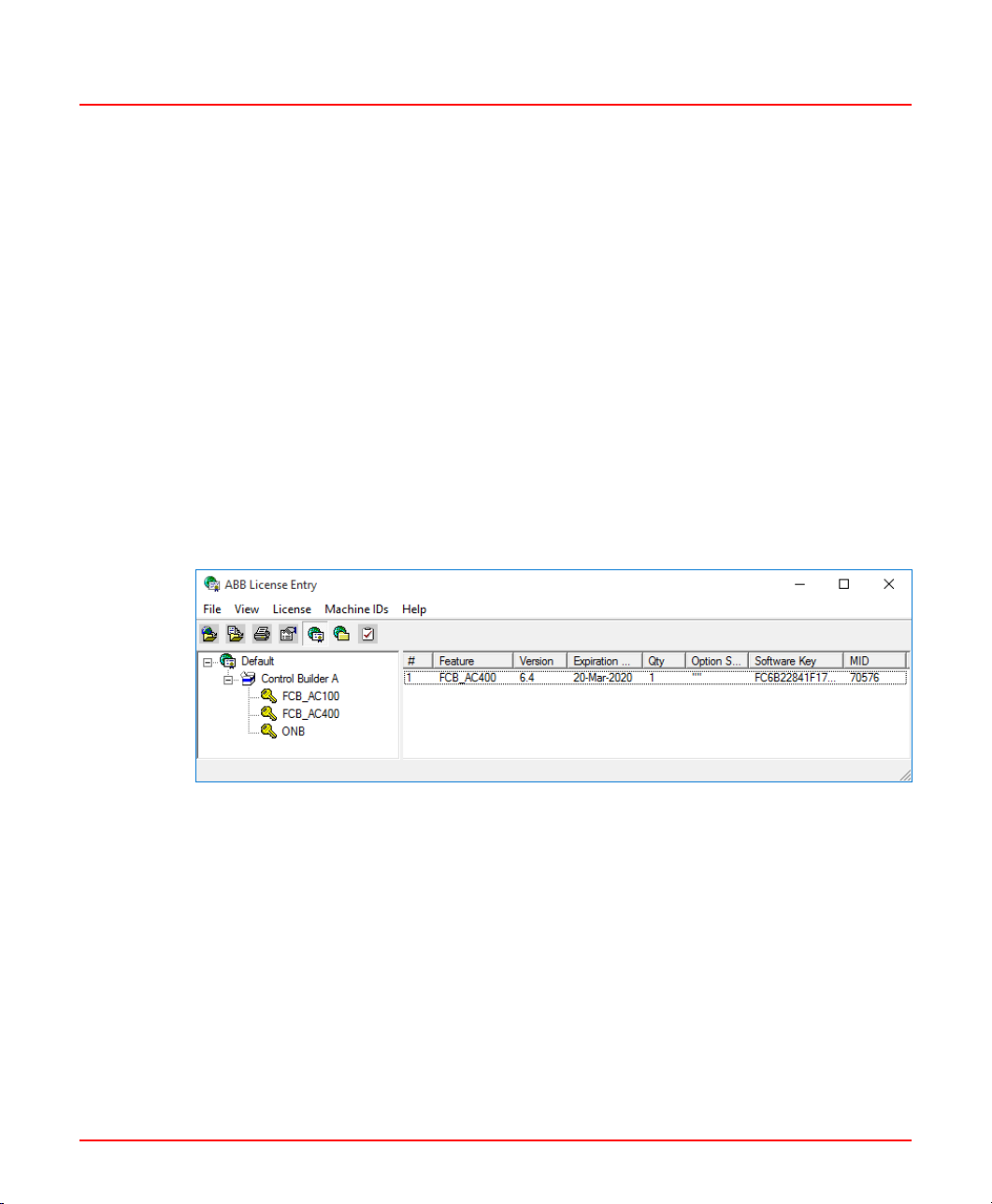
Three different licenses for Control Builder A:
• FCB_AC100
One licence is required for each PC running Function Chart Builder with node type
AC 100, e.g. AC 55, AC 70, AC 110 or AC 160.
• FCB_AC400
One licence is required for each PC running Function Chart Builder with node type
AC 400.
• ONB
One licence is required for each PC running On-line Builder.
Load Control Builder A licenses (.SLA file) into the licensing system with the ABB
License Entry tool:
In the ABB start menu choose ABB System 800xA > System > Licensing > License
Entry and then File > Load / Replaces Licenses.
Figure 1.3 shows an example of CBA licenses as presented in ABB Licence Entry tool:
Figure 1.3: CBA licenses in the ABB License Entry tool
3BSE066174R301 A 15
Page 16

1 Installation of Control Builder A
1.1 Installation Procedures
1.1.6 Control Builder A Products
1. Click on Install Control Builder A Suite, see Figure 1.2 to start installation of Control
Builder A products. The display shown in Figure 1.4 appears.
Figure 1.4: ABB Control Builder A Installation Wizard
2. Click Next to continue.
3BSE066174R301 A 16
Page 17

1 Installation of Control Builder A
1.1 Installation Procedures
3. Select Control Builder A products by modifying the check boxes .
Figure 1.5: Selecting the Control Builder A products
AMPL PC & DB Element Library for all supported targets will be installed as part of
Function Chart Builder.
Use the Browse button to change the Configuration Path and the Installation
Path and the Project Path. But it is recommended to keep the default values.
Figure 1.6 displays the Control Builder A products already installed.
3BSE066174R301 A 17
Page 18

1 Installation of Control Builder A
1.1 Installation Procedures
Figure 1.6: Control Builder A products installed
4. Click Next to continue.
There are no more installation selections for Application Builder, Function Chart
Builder and Bus Configuration Builder. Additional displays for On-line Builder are
described in Additional Displays During On-line Builder Installation on page 21.
5. Click Finish to exit.
Verify the Control Builder A installation
To verify the Control Builder A installation go to Control Panel > Program and Features.
Figure 1.7 shows an example of entries after a complete Control Builder A installation.
Each product can be uninstalled separately.
3BSE066174R301 A 18
Page 19

1 Installation of Control Builder A
1.1 Installation Procedures
Figure 1.7: Example for complete Control Builder A installation
Always uninstall AMPL PC and DB Element Libraries before Function Chart Builder.
Windows Firewall
Click on Configure Windows Firewall, see Figure 1.2, to configure the Windows Firewall
for the Control Builder A products. Only required if the computer will act as a server.
Restart the computer after Control Builder A is installed before configuring the firewall.
1.1.7 Manual Installation
A manual installation can be made as an alternative to the CBA Suite Installation
described in the previous section.
Click on Manual Installation in the Autorun display.
Click on 3rd Party Software & Tools and click on 800xA Common Install to install the
software manually. See figure 1.8.
3BSE066174R301 A 19
Page 20

1 Installation of Control Builder A
1.1 Installation Procedures
Figure 1.8: Autorun Window - 3rd Party Software and Tools
Central licensing and RNRP can be installed by clicking on Base Functionalities, see
figure 1.9.
Figure 1.9: Autorun Window - Base Functionalities
By clicking on Control Builder A, each of the Control Builder A products can be installed
individually by clicking on the corresponding product, see figure 1.10.
3BSE066174R301 A 20
Page 21

1 Installation of Control Builder A
1.1 Installation Procedures
Figure 1.10: Autorun Window - Control Builder A
AMPL PC & DB Element Library must be installed after Function Chart Builder is
installed.
1.1.8 Additional Displays During On-line Builder Installation
Some additional selections must be made during On-line Builder installation:
3BSE066174R301 A 21
Page 22

1 Installation of Control Builder A
1.1 Installation Procedures
Figure 1.11: Selecting the location for the Engineering Board
More info about PU410, including configuration of Network Interface Card, can be found
in section PU410.
Driver Installation
Figure 1.12 displays for about two minutes during the PU410 driver installation. 13 driver
instances and 13 WudfHost processes (visible in the Windows Task Manager) will be
created by the driver installation.
3BSE066174R301 A 22
Page 23

1 Installation of Control Builder A
1.1 Installation Procedures
Figure 1.12: Updating drivers during PU410 driver installation
1.1.9 Engineering Board setup
The Engineering Board setup (EBSetup) window is displayed if LOCAL was selected as
Engineering Board location during installation.
To configure the Engineering board:
1. Insert the MB300 Network number of the Engineering Board in the Network 1/2 field.
2. Insert the MB300 node number in the Node field.
3BSE066174R301 A 23
Page 24

1 Installation of Control Builder A
1.2 Server and Client Configuration
3. Select the MasterBus protocols: MB300, MB300F or MB300E in the Protocol field.
Figure 1.13: Configuring the EBSetup
4. Click OK to continue.
1.2 Server and Client Configuration
Function Chart Builder (FCB) and On-line Builder (ONB) can run in a client/server
configuration. The user interface is running in the client and the controller connected to
the servers, see figure 1.14.
3BSE066174R301 A 24
Page 25

1 Installation of Control Builder A
1.2 Server and Client Configuration
Figure 1.14: Configuration Diagram
The communication between client and server is based on DCOM which require some
configurations described in the rest of this section.
1.2.1 Server Configuration - DCOM
The following DCOM settings are required on servers to enable access in CBA from
clients:
1. Press Flag + R, select Run and type dcomcnfg.
2. Click on Component Services > Computers > My Computer, right click and select
Properties.
3BSE066174R301 A 25
Page 26

1 Installation of Control Builder A
1.2 Server and Client Configuration
3. Select the Default Properties tab, check Enable Distributed COM on this
computer as shown in Figure 1.15
Figure 1.15: Enabling Distributed COM on this computer
3BSE066174R301 A 26
Page 27

1 Installation of Control Builder A
1.2 Server and Client Configuration
4. If server for ONB, browse to AdvaBuild Engineering Board Server in the main
DCOM config window. If server for FCB, browse to AdvaBuild Communicator as
shown in Figure 1.16.
Figure 1.16: Selecting component services
3BSE066174R301 A 27
Page 28

1 Installation of Control Builder A
1.2 Server and Client Configuration
5. Right click, select Properties and click on Security tab.
Figure 1.17: Security settings
6. Select Customize and click Edit... in the Launch and Activation Permissions
area.
3BSE066174R301 A 28
Page 29

1 Installation of Control Builder A
1.2 Server and Client Configuration
7. Add the user group IndustrialITUser and check Allow option for all listed permissions
and click OK as shown in Figure 1.18.
Figure 1.18: Setting the Launch and Activation Permission
You can replace IndustrialITUserS with the user group or the user(s) you want to
allow access to CBA from Clients. This is applicable for the rest of the configuration.
3BSE066174R301 A 29
Page 30

1 Installation of Control Builder A
1.2 Server and Client Configuration
8. Select the Identity tab, check The launching user and click OK.
Figure 1.19: Selecting the user account to run this application
3BSE066174R301 A 30
Page 31

1 Installation of Control Builder A
1.2 Server and Client Configuration
1.2.2 Client configuration – Engineering Board Setup
Configure the following on clients with CBA installed. Enter the servers with the CBA
option ONB installed that are planned to be used for connection to the controllers in the
Engineering Board Setup dialog as follows:
1. In ABB Start menu select ABB Advant Master > Control Builder A > Utilities >
Engineering Board Setup.
2. Select the Use Engineering Board of the following servers as shown in Figure
1.20 to add the concerned servers. Click OK.
Figure 1.20: Adding servers using the EBSetup dialog box
3BSE066174R301 A 31
Page 32

1 Installation of Control Builder A
1.2 Server and Client Configuration
3. The On-line Builder tries to use an engineering board on a server starting with the
first computer in the list. The first running and not locked PC is used as server.
• Click the Add button to add another computer to the server list.
• Click Disable to disable a PC for use as Engineering Board server.
• Click Delete to remove a PC from the Engineering Board server list.
• Use the Move Up and Move Down buttons to rearrange the listed servers.
• Use the Test Server button to test the selected Engineering Board Server as
shown in Figure 1.21.
Figure 1.21: Testing the Engineering Board Server
Result from Connect Call shows text containing the result of the connect call.
The most common messages are:
• The operation completed successfully
The server PC is correctly configured and is able to work as server for On-line
Builder.
• The RPC server is unavailable
3BSE066174R301 A 32
Page 33

1 Installation of Control Builder A
1.3 PU410 External Engineering Board
This message occurs when the server PC could not be reached. Possible
reasons for this are that the server might be switched off or the network
connection fails
• Access is denied
User is not allowed to access this server PC.
• Class not registered
On-line Builder is not installed on the server PC or the registration is deleted.
View Server Events and View Client Events
You can inspect any event on the server side by pressing View Server Events. The
same can be done for events on the client.
Locked by
If a server is locked, the locking user is displayed in the Locked by control.
Unlock
Use this button to unlock the server. Unlock is not allowed if the server is a Connectivity
Server.
The session established by this user is interrupted!
1.3 PU410 External Engineering Board
1.3.1 Introduction
The external RTA unit PU410 replaces the engineering board PU516. PU410 is a
standalone hardware unit which supports both single and dual point to point connection
via Ethernet. Single or redundant connection with MasterBus 300 is enabled via RJ-45
connectors. It also has one port for direct connection to a AC 400 controller.
3BSE066174R301 A 33
Page 34

1 Installation of Control Builder A
1.3 PU410 External Engineering Board
1.3.2 PU410 Specification
• Connectors
– Two shielded RJ-45 connectors for 100Mbit/s full duplex communication with
the PC.(PC 1 and 2 ports)
– Two shielded RJ-45 connectors for 10Mbit/s half duplex communication with
MasterBus 300/300E or eDCN control network. (MB300/eDCN 1 and 2 ports)
– Two 15-pos DSUB socket connector for RS232 and RS422 communication
with Control Builder A, CBA. (CBA port)
– One 9-pos DSUB socket connector for RS232 communication for debug and
upgrading of firmware. (SERVICE port)
• Power
100-230V AC, 50-60 Hz.
• Power consumption
Typical 12W without I/O connected. Maximum 25W.
• Size
HxWxD (mm): 45 x 433 x 243.
• Net weight: 3.2 kg.
3BSE066174R301 A 34
Page 35

1 Installation of Control Builder A
1.3 PU410 External Engineering Board
The information label shown in figure 1.22 is attached underneath the unit.
Figure 1.22: PU410 Information label
In case of rack assembly, place the PU410 unit so that the connectors and the reset
button are within reach.
Before returning the PU410 unit for maintenance or repair, always remove accessories
such as brackets and cables.
3BSE066174R301 A 35
Page 36

F P
R IP
Rear View
F P
RIP
Front View
PU410
ABB
SERVICE
PC
1
2
MB300/eDCN
1
2
CBA DCN2 DCN1
9-pos Dsub
socket
RJ-45
connectors
15-pos Dsub
socket
connector
connector
IEC 320
power
connector
Reset switch
LED indicators meaning, front and rear:
LED
indicators
P= Power (green)
F = Fault (red)
IP = IP address reset (yellow)
R = Run (green ashing)
Two spare
LEDs
Ventilation
holes
Ventilation
holes
1 Installation of Control Builder A
1.3 PU410 External Engineering Board
Figure 1.23 shows the rear and front view of PU410.
Figure 1.23: Front and rear view of PU410
Since the PU410 unit includes a supervised fan it is recommended to check the fan and
vacuum clean the unit from time to time.
If a fan problem is detected the red fault LED will be illuminated and the unit will shut
down. The red fault LED will still be illuminated until the unit is reset, even if the fan
problem disappears.
The red fault LED can illuminate for other problems as well.
3BSE066174R301 A 36
Page 37

Two brackets included for 19”
rack mounting
Two feets included
for stand alone
mounting
1 Installation of Control Builder A
1.3 PU410 External Engineering Board
The red fault LED will also illuminate for a few seconds at PU410 start-up.
1.3.3 Mechanical Installation
The PU410K01 kit includes brackets for 19” rack mount and for floor or desktop mounting.
Figure 1.24: Brackets for PU410 Installation in 19" rack or stand alone
Connection to AC 400
Connect PU410 to AC 400 controller directly by using CBA port or use the MB300 ports
to connect via MB300.
Connection to Engineering Station
The PU410 unit has two ports called PC 1 and 2 for connection to the Engineering Station.
Only one port is necessary for the communication but if redundancy is wanted both ports
can be used if RNRP is configured.
3BSE066174R301 A 37
Page 38

1 Installation of Control Builder A
1.3 PU410 External Engineering Board
Figure 1.25: Connecting PU410 to Engineering station
• Always use shielded Cat 5e (or better) twisted pair cross-over cables to reduce
electric noise disturbances. The maximum cable length is 30m but keep cable length
as short as possible.
• The default IP addresses of PU410 are for the PC 1 port 172.16.168.50 and for the
PC 2 port 172.17.168.50.
3BSE066174R301 A 38
Page 39

1 Installation of Control Builder A
1.3 PU410 External Engineering Board
• The recommended IP address for the Network Interface Card, NIC, in the Engineering
Station is 172.16.168.1 with subnet mask 255.255.252.0 when using single cable.
Figure 1.26: Internet Protocol (TCP/IP) Properties
• The default IP address of PU410 and identical IP address of NIC can be used in
multiple Engineering Stations, as 172.16.168.x and 172.17.168.x are ‘local’ IP
addresses.
• When using dual cables, the IP address of the additional NIC in the Engineering
Station is recommended to be 172.17.168.1 with subnet mask 255.255.252.0. The
status of the dual connection can be viewed in the RNRP network event monitor,
provided that RNRP is installed in Engineering Station.
3BSE066174R301 A 39
Page 40

1 Installation of Control Builder A
1.3 PU410 External Engineering Board
• When the connection between Engineering Station and PU410 is lost, e.g. due to
communication problem or power loss in PU410, it will be detected in the Engineering
Station after four seconds if RNRP is configured.
• The PU410 unit communicates with 100Mbit/s on the PC 1 and 2 ports. It is
recommended to configure the network interface card in the Engineering Station to
100Mbit/s full duplex.
Figure 1.27: Example of NIC Configuration
• RNRP can be used to supervise the communication between the Engineering Station
and PU410. The detection time for lost communication will increase from 4s to at
least 30s if RNRP is not configured correctly. No additional RNRP configuration is
required when the default implicit configuration of RNRP is used.
3BSE066174R301 A 40
Page 41

1 Installation of Control Builder A
1.3 PU410 External Engineering Board
• If the default implicit configuration of RNRP is modified, an explicit configuration of
RNRP must be added for the PU410 connection. Configure "Network area" to 10
and "Network area local" to 1 if the default IP addresses for PU410 are used.
• The IP address and subnet mask of PU410 can be modified by a tool, but this is
required only if Network area 10 (NetId 172.16.40.0) is already used in the
Engineering Station (refer to Modify IP address of PU410 on page 41). RNRP
requires the IP address of the first port of PU410 to always start with 172.16 (in
PU410 FW version 1.0.1.0 and earlier). The default IP addresses of PU410 are
restored by pressing and holding down the reset switch of PU410 for about 20
seconds until the yellow IP LED is lit.
Modify IP address of PU410
The IP address of PU410 shall be modified only if NetId 172.16.40.0 is already used
in Engineering Station.
Execute the following steps to modify the IP address of PU410.
1. Start the ManagementTool.exe located in
C:\AdvaBNT\ONB\32r1\Driver PU410.
2. Select the IP Config view and click Get.
3. Modify the IP settings and click Set.
The modified IP address will be effective when the PU410 is reset, in the Reset view or
by pressing the reset switch of PU410 unit.
3BSE066174R301 A 41
Page 42

1 Installation of Control Builder A
1.3 PU410 External Engineering Board
Figure 1.28: IP Config view of Management Tool
After modifying the IP address of PU410, the Target IP address of Management Tool
must be modified in the Settings menu to get contact again. The Target IP address
is shown at the bottom left in the Management Tool.
A registry setting must be modified in the Engineering Station to match the modified IP
address of PU410 (see Figure 8). Right click the IP address, select Modify from the
context menu, and enter the Primary IP address of PU410. This modification is effective
when the Engineering Station is restarted.
3BSE066174R301 A 42
Page 43

1 Installation of Control Builder A
1.3 PU410 External Engineering Board
Figure 1.29: IP address setting in Registry
3BSE066174R301 A 43
Page 44

3BSE066174R301 A 44
Page 45

Revision History
Revision History
Revision History
This section provides information on the revision history of this User Manual.
Revision History
The following table lists the revision history of this User Manual.
The revision index of this User Manual is not related to the Control Builder A revision.
Revision
Index
DateDescription
August 2014Published for Control Builder A 1.4/0-
April 2019Published for Control Builder A 1.4/2A
3BSE066174R301 A 45
Page 46

3BSE066174R301 A 46
Page 47

Page 48

www.abb.com/800xA
www.abb.com/controlsystems
800xA is a registered or pending trademark
of ABB. All rights to other trademarks reside
with their respective owners.
We reserve the right to make technical
changes to the products or modify the
contents of this document without prior
notice. With regard to purchase orders,
the agreed particulars shall prevail.
ABB does not assume any responsibility
for any errors or incomplete information in
this document.
We reserve all rights to this document
and the items and images it contains.
The reproduction, disclosure to third parties
or the use of the content of this document
– including parts thereof – are prohibited
without ABB’s prior written permission.
Copyright © 2019 ABB.
All rights reserved.
3BSE066174R301 A
 Loading...