

Page 1
—
OPTIONS FOR ABB DRIVES
ACx-AP-x Assistant control panels
User’s manual
Page 2

—
List of related manuals
Tool and maintenance manuals Code (English)
Drive composer PC tool user's manual 3AUA0000094606
Option manuals and guides
ACx-AP-x Assistant control panels User’s manual 3AUA0000085685
CDPI-01 communication adapter module User’s manual 3AXD50000009929
DPMP-01 mounting platform for ACP-AP control panel 3AUA0000100140
DPMP-02/03 mounting platform for ACP-AP control
panel
You can find manuals and other product documents in PDF format on the Internet. See
section Document library on the Internet on the inside of the back cover. For manuals
not available in the Document library, contact your local ABB representative.
3AUA0000136205
Page 3

User’s manual
ACx-AP-x Assistant control panels
Table of contents
2018 ABB Oy. All Rights Reserved.
3AUA0000085685 Rev E
EN
EFFECTIVE: 2018-07-11
Page 4

Page 5

Table of contents 5
Table of contents
1. Introduction to the manual
What this chapter contains . . . . . . . . . . . . . . . . . . . . . . . . . . . . . . . . . . . . . . . . . . . . . . . . . . . . 9
Applicability . . . . . . . . . . . . . . . . . . . . . . . . . . . . . . . . . . . . . . . . . . . . . . . . . . . . . . . . . . . . . . . . 9
Compatibility . . . . . . . . . . . . . . . . . . . . . . . . . . . . . . . . . . . . . . . . . . . . . . . . . . . . . . . . . . . . . . 10
Safety . . . . . . . . . . . . . . . . . . . . . . . . . . . . . . . . . . . . . . . . . . . . . . . . . . . . . . . . . . . . . . . . . . . 10
Intended audience . . . . . . . . . . . . . . . . . . . . . . . . . . . . . . . . . . . . . . . . . . . . . . . . . . . . . . . . . . 10
Contents of the manual . . . . . . . . . . . . . . . . . . . . . . . . . . . . . . . . . . . . . . . . . . . . . . . . . . . . . . 10
2. Installation and start-up
What this chapter contains . . . . . . . . . . . . . . . . . . . . . . . . . . . . . . . . . . . . . . . . . . . . . . . . . . . 13
Installation . . . . . . . . . . . . . . . . . . . . . . . . . . . . . . . . . . . . . . . . . . . . . . . . . . . . . . . . . . . . . . . . 13
First start-up . . . . . . . . . . . . . . . . . . . . . . . . . . . . . . . . . . . . . . . . . . . . . . . . . . . . . . . . . . . . . . 14
Safety
3. Control panel overview
What this chapter contains . . . . . . . . . . . . . . . . . . . . . . . . . . . . . . . . . . . . . . . . . . . . . . . . . . . 17
Display, keys and parts . . . . . . . . . . . . . . . . . . . . . . . . . . . . . . . . . . . . . . . . . . . . . . . . . . . . . . 18
Display . . . . . . . . . . . . . . . . . . . . . . . . . . . . . . . . . . . . . . . . . . . . . . . . . . . . . . . . . . . . . . . . 19
Keys . . . . . . . . . . . . . . . . . . . . . . . . . . . . . . . . . . . . . . . . . . . . . . . . . . . . . . . . . . . . . . . . . . 20
Status LED . . . . . . . . . . . . . . . . . . . . . . . . . . . . . . . . . . . . . . . . . . . . . . . . . . . . . . . . . . . . . 22
USB connector . . . . . . . . . . . . . . . . . . . . . . . . . . . . . . . . . . . . . . . . . . . . . . . . . . . . . . . . . . 22
RJ-45 connector . . . . . . . . . . . . . . . . . . . . . . . . . . . . . . . . . . . . . . . . . . . . . . . . . . . . . . . . . 23
Type code label on the panel . . . . . . . . . . . . . . . . . . . . . . . . . . . . . . . . . . . . . . . . . . . . . . . 23
Type code label on the panel package . . . . . . . . . . . . . . . . . . . . . . . . . . . . . . . . . . . . . . . 23
Battery cover . . . . . . . . . . . . . . . . . . . . . . . . . . . . . . . . . . . . . . . . . . . . . . . . . . . . . . . . . . . 24
Wireless interface. . . . . . . . . . . . . . . . . . . . . . . . . . . . . . . . . . . . . . . . . . . . . . . . . . . . . . . . 24
4. Basic operation
What this chapter contains . . . . . . . . . . . . . . . . . . . . . . . . . . . . . . . . . . . . . . . . . . . . . . . . . . . 25
User interface overview . . . . . . . . . . . . . . . . . . . . . . . . . . . . . . . . . . . . . . . . . . . . . . . . . . . . . . 25
Control panel navigation . . . . . . . . . . . . . . . . . . . . . . . . . . . . . . . . . . . . . . . . . . . . . . . . . . . . . 26
Navigation memory . . . . . . . . . . . . . . . . . . . . . . . . . . . . . . . . . . . . . . . . . . . . . . . . . . . . . . 26
Home view . . . . . . . . . . . . . . . . . . . . . . . . . . . . . . . . . . . . . . . . . . . . . . . . . . . . . . . . . . . . . . . . 27
Navigating in the Home view . . . . . . . . . . . . . . . . . . . . . . . . . . . . . . . . . . . . . . . . . . . . . . . 27
Help . . . . . . . . . . . . . . . . . . . . . . . . . . . . . . . . . . . . . . . . . . . . . . . . . . . . . . . . . . . . . . . . . . . . . 28
Common user tasks . . . . . . . . . . . . . . . . . . . . . . . . . . . . . . . . . . . . . . . . . . . . . . . . . . . . . . . . . 29
Basic operation of the drive . . . . . . . . . . . . . . . . . . . . . . . . . . . . . . . . . . . . . . . . . . . . . . . . 29
Parameters. . . . . . . . . . . . . . . . . . . . . . . . . . . . . . . . . . . . . . . . . . . . . . . . . . . . . . . . . . . . . 29
System information and help . . . . . . . . . . . . . . . . . . . . . . . . . . . . . . . . . . . . . . . . . . . . . . . 30
Faults and warnings. . . . . . . . . . . . . . . . . . . . . . . . . . . . . . . . . . . . . . . . . . . . . . . . . . . . . . 30
Basic settings and assistants. . . . . . . . . . . . . . . . . . . . . . . . . . . . . . . . . . . . . . . . . . . . . . . 30
Backups . . . . . . . . . . . . . . . . . . . . . . . . . . . . . . . . . . . . . . . . . . . . . . . . . . . . . . . . . . . . . . . 31
Page 6

6 Table of contents
5. Functions in the main Menu
What this chapter contains . . . . . . . . . . . . . . . . . . . . . . . . . . . . . . . . . . . . . . . . . . . . . . . . . . . 33
Menu . . . . . . . . . . . . . . . . . . . . . . . . . . . . . . . . . . . . . . . . . . . . . . . . . . . . . . . . . . . . . . . . . . . 33
Navigating in the Menu . . . . . . . . . . . . . . . . . . . . . . . . . . . . . . . . . . . . . . . . . . . . . . . . . . . 34
Parameters . . . . . . . . . . . . . . . . . . . . . . . . . . . . . . . . . . . . . . . . . . . . . . . . . . . . . . . . . . . . . . . 34
Complete list . . . . . . . . . . . . . . . . . . . . . . . . . . . . . . . . . . . . . . . . . . . . . . . . . . . . . . . . . . . 34
By function . . . . . . . . . . . . . . . . . . . . . . . . . . . . . . . . . . . . . . . . . . . . . . . . . . . . . . . . . . . . 34
Favorites . . . . . . . . . . . . . . . . . . . . . . . . . . . . . . . . . . . . . . . . . . . . . . . . . . . . . . . . . . . . . . 35
Modified. . . . . . . . . . . . . . . . . . . . . . . . . . . . . . . . . . . . . . . . . . . . . . . . . . . . . . . . . . . . . . . 35
Adding parameters to the Home view . . . . . . . . . . . . . . . . . . . . . . . . . . . . . . . . . . . . . . . . 35
Editing parameters . . . . . . . . . . . . . . . . . . . . . . . . . . . . . . . . . . . . . . . . . . . . . . . . . . . . . . 35
Editing numeric parameters . . . . . . . . . . . . . . . . . . . . . . . . . . . . . . . . . . . . . . . . . . . . . . . 36
Editing selection list parameters . . . . . . . . . . . . . . . . . . . . . . . . . . . . . . . . . . . . . . . . . . . . 36
Editing bit-field parameters . . . . . . . . . . . . . . . . . . . . . . . . . . . . . . . . . . . . . . . . . . . . . . . . 38
Editing texts. . . . . . . . . . . . . . . . . . . . . . . . . . . . . . . . . . . . . . . . . . . . . . . . . . . . . . . . . . . . 38
Resetting counters . . . . . . . . . . . . . . . . . . . . . . . . . . . . . . . . . . . . . . . . . . . . . . . . . . . . . . 38
Assistants . . . . . . . . . . . . . . . . . . . . . . . . . . . . . . . . . . . . . . . . . . . . . . . . . . . . . . . . . . . . . . . 39
Launching an assistant . . . . . . . . . . . . . . . . . . . . . . . . . . . . . . . . . . . . . . . . . . . . . . . . . . . 39
Generating a QR code . . . . . . . . . . . . . . . . . . . . . . . . . . . . . . . . . . . . . . . . . . . . . . . . . . . 39
Energy efficiency . . . . . . . . . . . . . . . . . . . . . . . . . . . . . . . . . . . . . . . . . . . . . . . . . . . . . . . . . . 40
Event log . . . . . . . . . . . . . . . . . . . . . . . . . . . . . . . . . . . . . . . . . . . . . . . . . . . . . . . . . . . . . . . . 40
History graphs . . . . . . . . . . . . . . . . . . . . . . . . . . . . . . . . . . . . . . . . . . . . . . . . . . . . . . . . . . . . 41
Trends . . . . . . . . . . . . . . . . . . . . . . . . . . . . . . . . . . . . . . . . . . . . . . . . . . . . . . . . . . . . . . . . 41
Load profile . . . . . . . . . . . . . . . . . . . . . . . . . . . . . . . . . . . . . . . . . . . . . . . . . . . . . . . . . . . . 41
Backups . . . . . . . . . . . . . . . . . . . . . . . . . . . . . . . . . . . . . . . . . . . . . . . . . . . . . . . . . . . . . . . . . 41
Creating a parameter backup . . . . . . . . . . . . . . . . . . . . . . . . . . . . . . . . . . . . . . . . . . . . . . 42
Restoring a parameter backup . . . . . . . . . . . . . . . . . . . . . . . . . . . . . . . . . . . . . . . . . . . . . 42
System info . . . . . . . . . . . . . . . . . . . . . . . . . . . . . . . . . . . . . . . . . . . . . . . . . . . . . . . . . . . . . . . 43
Settings . . . . . . . . . . . . . . . . . . . . . . . . . . . . . . . . . . . . . . . . . . . . . . . . . . . . . . . . . . . . . . . . . 44
Primary settings . . . . . . . . . . . . . . . . . . . . . . . . . . . . . . . . . . . . . . . . . . . . . . . . . . . . . . . . . . . 45
I/O . . . . . . . . . . . . . . . . . . . . . . . . . . . . . . . . . . . . . . . . . . . . . . . . . . . . . . . . . . . . . . . . . . . . . . 46
Diagnostics . . . . . . . . . . . . . . . . . . . . . . . . . . . . . . . . . . . . . . . . . . . . . . . . . . . . . . . . . . . . . . . 46
6. Functions in the Options menu
What this chapter contains . . . . . . . . . . . . . . . . . . . . . . . . . . . . . . . . . . . . . . . . . . . . . . . . . . . 49
Options menu . . . . . . . . . . . . . . . . . . . . . . . . . . . . . . . . . . . . . . . . . . . . . . . . . . . . . . . . . . . . . 49
Setting the reference . . . . . . . . . . . . . . . . . . . . . . . . . . . . . . . . . . . . . . . . . . . . . . . . . . . . . . . 50
Editing the contents of the Home view . . . . . . . . . . . . . . . . . . . . . . . . . . . . . . . . . . . . . . . . . . 50
7. Control of multiple drives
What this chapter contains . . . . . . . . . . . . . . . . . . . . . . . . . . . . . . . . . . . . . . . . . . . . . . . . . . . 53
Connecting multiple drives to a control panel . . . . . . . . . . . . . . . . . . . . . . . . . . . . . . . . . . . . . 53
Selecting drive menu . . . . . . . . . . . . . . . . . . . . . . . . . . . . . . . . . . . . . . . . . . . . . . . . . . . . . . . 54
Selecting a drive . . . . . . . . . . . . . . . . . . . . . . . . . . . . . . . . . . . . . . . . . . . . . . . . . . . . . . . . 54
Panel features with multiple drives . . . . . . . . . . . . . . . . . . . . . . . . . . . . . . . . . . . . . . . . . . . . . 54
Panel views. . . . . . . . . . . . . . . . . . . . . . . . . . . . . . . . . . . . . . . . . . . . . . . . . . . . . . . . . . . . 54
The Help page. . . . . . . . . . . . . . . . . . . . . . . . . . . . . . . . . . . . . . . . . . . . . . . . . . . . . . . . . . 54
Graph data . . . . . . . . . . . . . . . . . . . . . . . . . . . . . . . . . . . . . . . . . . . . . . . . . . . . . . . . . . . . 55
Page 7

Table of contents 7
Backups . . . . . . . . . . . . . . . . . . . . . . . . . . . . . . . . . . . . . . . . . . . . . . . . . . . . . . . . . . . . . . . 55
Customized content . . . . . . . . . . . . . . . . . . . . . . . . . . . . . . . . . . . . . . . . . . . . . . . . . . . . . . 55
Assistants. . . . . . . . . . . . . . . . . . . . . . . . . . . . . . . . . . . . . . . . . . . . . . . . . . . . . . . . . . . . . . 55
Faults and warnings with multiple drives . . . . . . . . . . . . . . . . . . . . . . . . . . . . . . . . . . . . . . . . . 55
Faults and warnings in the currently selected drive . . . . . . . . . . . . . . . . . . . . . . . . . . . . . . 55
Faults and warnings in other drives . . . . . . . . . . . . . . . . . . . . . . . . . . . . . . . . . . . . . . . . . . 55
8. Fault tracing
What this chapter contains . . . . . . . . . . . . . . . . . . . . . . . . . . . . . . . . . . . . . . . . . . . . . . . . . . . 57
Identifying error and warning messages . . . . . . . . . . . . . . . . . . . . . . . . . . . . . . . . . . . . . . . . . 57
Faults . . . . . . . . . . . . . . . . . . . . . . . . . . . . . . . . . . . . . . . . . . . . . . . . . . . . . . . . . . . . . . . . . . . . 59
Warnings . . . . . . . . . . . . . . . . . . . . . . . . . . . . . . . . . . . . . . . . . . . . . . . . . . . . . . . . . . . . . . . . . 59
9. Service and maintenance
What this chapter contains . . . . . . . . . . . . . . . . . . . . . . . . . . . . . . . . . . . . . . . . . . . . . . . . . . . 61
Removing the control panel cover . . . . . . . . . . . . . . . . . . . . . . . . . . . . . . . . . . . . . . . . . . . . . . 61
Cleaning the control panel . . . . . . . . . . . . . . . . . . . . . . . . . . . . . . . . . . . . . . . . . . . . . . . . . . . . 61
Cleaning the connectors . . . . . . . . . . . . . . . . . . . . . . . . . . . . . . . . . . . . . . . . . . . . . . . . . . . . . 62
Replacing the battery . . . . . . . . . . . . . . . . . . . . . . . . . . . . . . . . . . . . . . . . . . . . . . . . . . . . . . . . 62
Control panel software updates . . . . . . . . . . . . . . . . . . . . . . . . . . . . . . . . . . . . . . . . . . . . . . . . 62
Recycling instructions and environmental information . . . . . . . . . . . . . . . . . . . . . . . . . . . . . . 62
10. Panel-to-PC USB connection
What this chapter contains . . . . . . . . . . . . . . . . . . . . . . . . . . . . . . . . . . . . . . . . . . . . . . . . . . . 63
USB connection . . . . . . . . . . . . . . . . . . . . . . . . . . . . . . . . . . . . . . . . . . . . . . . . . . . . . . . . . . . . 63
Connecting control panel to PC USB . . . . . . . . . . . . . . . . . . . . . . . . . . . . . . . . . . . . . . . . . . . 64
Connecting a PC tool to a drive through the control panel . . . . . . . . . . . . . . . . . . . . . . . . . . . 65
Connecting in local control mode . . . . . . . . . . . . . . . . . . . . . . . . . . . . . . . . . . . . . . . . . . . . 65
Connecting in remote control mode . . . . . . . . . . . . . . . . . . . . . . . . . . . . . . . . . . . . . . . . . . 65
Transferring files between the control panel and a PC . . . . . . . . . . . . . . . . . . . . . . . . . . . . . . 66
11. Technical data
What this chapter contains . . . . . . . . . . . . . . . . . . . . . . . . . . . . . . . . . . . . . . . . . . . . . . . . . . . 67
Connectors . . . . . . . . . . . . . . . . . . . . . . . . . . . . . . . . . . . . . . . . . . . . . . . . . . . . . . . . . . . . . . . 67
Display . . . . . . . . . . . . . . . . . . . . . . . . . . . . . . . . . . . . . . . . . . . . . . . . . . . . . . . . . . . . . . . . . . . 67
Battery . . . . . . . . . . . . . . . . . . . . . . . . . . . . . . . . . . . . . . . . . . . . . . . . . . . . . . . . . . . . . . . . . . . 68
Dimensions and weight . . . . . . . . . . . . . . . . . . . . . . . . . . . . . . . . . . . . . . . . . . . . . . . . . . . . . . 68
Degrees of protection . . . . . . . . . . . . . . . . . . . . . . . . . . . . . . . . . . . . . . . . . . . . . . . . . . . . . . . 68
Materials . . . . . . . . . . . . . . . . . . . . . . . . . . . . . . . . . . . . . . . . . . . . . . . . . . . . . . . . . . . . . . . . . 69
Environmental limits . . . . . . . . . . . . . . . . . . . . . . . . . . . . . . . . . . . . . . . . . . . . . . . . . . . . . . . . 69
IEC compliance . . . . . . . . . . . . . . . . . . . . . . . . . . . . . . . . . . . . . . . . . . . . . . . . . . . . . . . . . . . . 69
LCD specifications . . . . . . . . . . . . . . . . . . . . . . . . . . . . . . . . . . . . . . . . . . . . . . . . . . . . . . . . . . 70
Bluetooth interface . . . . . . . . . . . . . . . . . . . . . . . . . . . . . . . . . . . . . . . . . . . . . . . . . . . . . . . . . . 70
Bluetooth encryption . . . . . . . . . . . . . . . . . . . . . . . . . . . . . . . . . . . . . . . . . . . . . . . . . . . . . . . . 70
FCC and Industry Canada certifications . . . . . . . . . . . . . . . . . . . . . . . . . . . . . . . . . . . . . . . . . 71
FCC ID: 2AFNGAPWSERIES . . . . . . . . . . . . . . . . . . . . . . . . . . . . . . . . . . . . . . . . . . . . . . 71
IC: 20555-APWSERIES . . . . . . . . . . . . . . . . . . . . . . . . . . . . . . . . . . . . . . . . . . . . . . . . . . . 71
Disclaimers . . . . . . . . . . . . . . . . . . . . . . . . . . . . . . . . . . . . . . . . . . . . . . . . . . . . . . . . . . . . . . . 72
Page 8

8 Table of contents
Generic disclaimer . . . . . . . . . . . . . . . . . . . . . . . . . . . . . . . . . . . . . . . . . . . . . . . . . . . . . . 72
Cybersecurity disclaimer . . . . . . . . . . . . . . . . . . . . . . . . . . . . . . . . . . . . . . . . . . . . . . . . . . 72
Further information
Page 9
Introduction to the manual 9
1
Control panel
Product type: ACS-AP-I
HW version: D
FW version: GPAPI v5.80
?
Introduction to the manual
What this chapter contains
The chapter describes the applicability, compatibility, intended audience and the
contents of this manual.
Applicability
This manual applies to the following panel types and their versions:
Control panel type ACS-AP-I and
ACS-AP-S
Hardware version C or later A or later C or later A or later
Software version 4.61 or later 5.01 or later 5.00 or later 5.40 or later
ACS-AP-W ACH-AP-H ACH-AP-W
You can also view panel details in the panel itself using either of the two methods:
• With panel still not powered, press and hold
(help) button, then power up the panel through
USB or drive.
or
• With panel powered up, go to Menu
info
→ Control panel.
→ System
Page 10

10 Introduction to the manual
Note: The images and instructions in this manual are examples, each based on a
specific control panel and drive type combination. The details may vary with different
control panels or drive types.
Compatibility
The following drive(s) are compatible with these panel types.
Control
panel type
Drive ACS380, ACS480,
ACS-AP-I ACS-AP-S ACS-AP-W ACH-AP-H,
ACH-AP-W
ACS530, ACS560,
ACS580, ACQ580,
ACS860, ACS880
ACS380, ACS4 80,
ACS530, ACS5 60,
ACS580
ACS380, ACS480,
ACS530, ACS560,
ACS580, ACQ580 ,
ACS860, ACS880
ACH480,
ACH580 , ACQ580
Note: This table may not be comprehensive. See the appropriate drive manual for
more details.
Safety
Follow all safety instructions delivered with the drive.
Intended audience
This manual is intended for persons who use an ACx-AP-x Assistant control panel.
Contents of the manual
The information in the manual is organized in the following chapters:
• Installation and start-up describes the installation and start-up of the control panel.
• Control panel overview describes the main parts of the control panel and their
functions.
• Basic operation describes the menu structure, views and basic functions of the
control panel.
• Functions in the main Menu describes the functions in the main Menu.
• Functions in the Options menu describes the functions in the Options menu.
• Control of multiple drives describes how to control several drives with one control
panel.
• Fault tracing describes how to identify different fault and warning messages and
how to solve problem situations.
• Service and maintenance describes service-related functions and routine
maintenance tasks.
• Panel-to-PC USB connection describes interaction between a PC and the control
panel.
Page 11

Introduction to the manual 11
• Technical data describes the parts, dimensions and materials of the control panel,
and other technical data about the control panel.
Page 12

12 Introduction to the manual
Page 13
Installation and start-up 13
2
A
B
Installation and start-up
What this chapter contains
The chapter describes how to install and start-up the Assistant control panel for the
first time.
Installation
Attach the control panel directly to the drive
or use a separate mounting kit (for
example, for cabinet door mounting).
To attach the control panel,
1. Place its bottom end into the bottom of
the slot in the drive (A).
2. Pivot the control panel and push the
upper part (B) until you hear a click.
To detach the control panel,
1. Release the control panel by pressing
the clip (B).
2. Pull the upper end of the control panel
out of the slot in the drive.
Page 14
14 Installation and start-up
First start-up
To start-up the control panel for the first time,
follow the instructions:
1. Obey all drive-specific safety precautions.
2. Install the control panel. See instructions
in Installation (page 13).
3. Power up the drive.
The control panel start-up begins
automatically.
shows the language selection view.
4. Use or to select a language.
5. Press to confirm your selection
Wait until the control panel completes
uploading the language file. Its progress is
indicated by a progress bar.
If there is a Basic set-up assistant in the drive, or if the control panel already contains
a compatible backup (or backups) that could be copied to the drive, the control panel
prompts a question.
Wait until the control panel
.
Page 15
Installation and start-up 15
Once you are in the Home view, the control panel is ready for use.
Page 16

16 Installation and start-up
Page 17

Control panel overview 17
3
Control panel overview
What this chapter contains
The chapter describes the display, keys and main parts of the Assistant control panel.
Page 18
18 Control panel overview
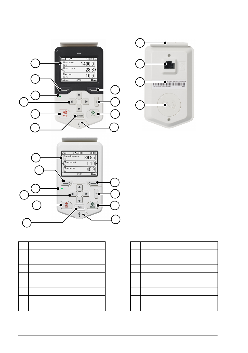
12
11
13
14
1
4
3
6
7 8
5
10
2
9
1
2
3
4
5
6
15
16
17
10
Display, keys and parts
1 Display 10 USB connector
2 Left softkey 11 C lip
3 Right softkey 12 RJ-45 connector
4 Status LE D 13 Type code label on the panel
5 Help 14 Battery cover
6 Arrow keys 15 Off
7Stop (see Start and Stop)16Hand
8 Start (see Start and Stop)17Auto
9 Local/Remote (see Loc/Rem)
Page 19
Control panel overview 19
1
2
3
4
6
7
7
5
8
Display
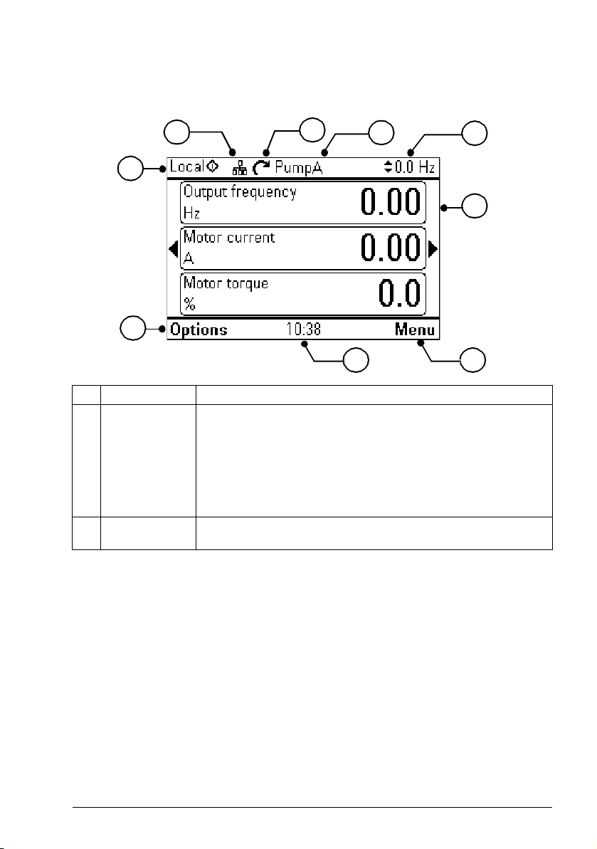
In most views, the following control panel elements are shown on the display:
No. Panel element Function
1 Control location
and related icons
2 Panel bus Indicates that there are more than one drive connected to this
Indicates how the drive is controlled:
No text: The drive is in local control, but controlled from another
device. The icons in the top pane indicate which actions are allowed.
Local: The drive is in local control, that is, controlled from the control
panel.
Remote: The drive is in remote control, that is, controlled through I/O
or fieldbus.
panel.To switch to another drive, go to Options
→ Select drive.
Page 20

20 Control panel overview
Status icon Animation Drive status
- Stopped
- Stopped, start inhibited
Blinking Stopped, start command given but start inhibited
Blinking Faulted
Blinking Running, at reference, but the reference value is 0
Rotating Running, not at reference
Rotating Running, at reference
No. Panel element Function
3 Status icon Indicates the status of the drive and the motor. The direction of the
arrow indicates forward (clockwise) or reverse (counter-clockwise)
active reference direction.
Note: For non-rotating driven equipment, the numbers 1 and 0 are
used to indicate that the drive is running or stopped, respectively.
4 Drive name If a name is given, it is displayed at the top pane. By default, it is
blank. You can change the name in the Primary settings (page 45) or
Settings menu (page 44).
5 Reference value Speed, frequency and so on, are shown with its unit. For information
6 Content area Displays the actual content of the view in this area. The content
7Softkey
selections
8 Clock Displays the current time. The time can be changed through the
on changing the reference value, see Setting the reference (page 50).
varies from view to view. The example view above is the main view of
the control panel which is called the Home view.
Displays the functions of the softkeys (
context.
Primary settings (page 45) or Settings menu (page 44).
and ) in a given
You can adjust the display contrast and backlight functionality in the Primary settings
(page 45) or Settings menu (page 44).
Keys
The keys of the control panel are described
below.
Left softkey
The left softkey ( ) is usually used for
exiting and canceling. Its function in a given
situation is shown by the softkey selection in
the bottom left corner of the display.
Holding down exits each view in turn until you are back in the Home view. This
function does not work in special screens.
Page 21
Control panel overview 21
?
Loc/Rem
Right softkey
The right softkey ( ) is usually used for selecting, accepting and confirming. The
function of the right softkey in a given situation is shown by the softkey selection in
the bottom right corner of the display.
Arrow keys
The up and down arrow keys ( and ) are used to highlight selections in menus
and selection lists, to scroll up and down on text pages, and to adjust values when,
for example, setting the time, entering a passcode or changing a parameter value.
The left and right arrow keys ( and ) are used to move the cursor left and right in
parameter editing and to move forward and backward in assistants. In menus, and
function the same way as
and , respectively.
Help
The help key (
) opens a help page. The help page is context-sensitive, in other
words, the content of the page is relevant to the menu or view in question. See Help
(page 28) for more information on the help page.
Start and Stop
In local control, the start key ( ) and the stop key ( ) start and stop the drive,
respectively.
Off
In Hand and Auto control, the Off key ( ) is used to stop the drive.
Hand
The Hand key ( ) is used to start the drive in local mode. When the drive is
running, if you switch to Auto mode, the drive changes the control location to Remote
mode and the drive may stop.
Auto
The Auto key ( ) is used to run the drive automatically. The control is selected
from primary or secondary or any DI. You can give the reference inputs in Menu ->
Primary settings -> Drive or by setting the values in parameter groups 19 and 20.
Loc/Rem
The location key ( ) is used to switch the control between the control panel
(Local) and remote connections (Remote). When switching from Remote to Local
while the drive is running, the drive keeps running at the same speed. When
switching from Local to Remote, the status of the remote location is adopted. See the
drive-specific firmware manual for more details.
Page 22
22 Control panel overview
Key shortcuts
The table below lists key shortcuts and combinations. Simultaneous key presses are
indicated by the plus sign (+).
Shortcut Available in... Effect
+ + any view Save a screenshot. Up to fifteen images can be stored
in the control panel memory. For instructions on how to
transfer the images into a PC, see section Transferring
files between the control panel and a PC (page 66).
+ ,
any view Adjust backlight brightness.
+
+ ,
any view Adjust display contrast.
+
or Home view Adjust reference.
+ parameter edit
views
Revert an editable parameter to its default value.
+ any view Show/hide parameter index and parameter group
numbers.
(keep down)
any view Return to Home view by pressing down the key until
Home view is shown.
Status LED
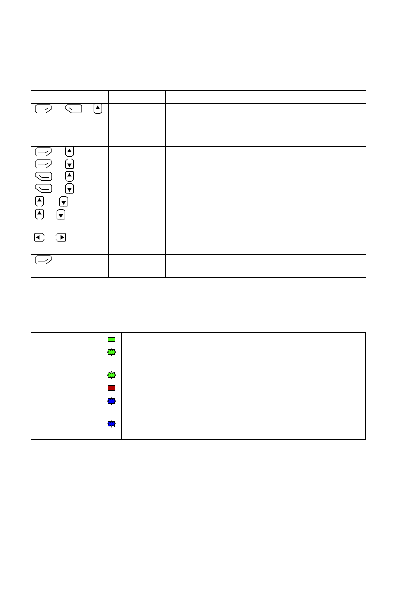
The control panel has a status LED that indicates if there are any faults or warnings
present. The table below shows the meaning of the LED indications.
Green, continuous The drive is functioning normally.
Green, flickering Data is transferred between the PC tool and drive through the USB
connection of the control panel.
Green, blinking There is an active warning in the drive.
Red, continuous There is an active fault in the drive.
Blue, blinking Bluetooth interface is enabled.It is in discoverable mode and ready
Blue, flickering Data is transfered through the Bluetooth interface of the control
for pairing.
panel.
For further information on fault and warning indications, see Identifying error and
warning messages (page 57).
USB connector
The USB connector is used for connecting the control panel to a PC. When
connected, the control panel acts as an USB adapter for data transfer between the
PC tool and the drive. It is also possible to transfer data between the PC and the
control panel through the USB connection.
Page 23
Control panel overview 23
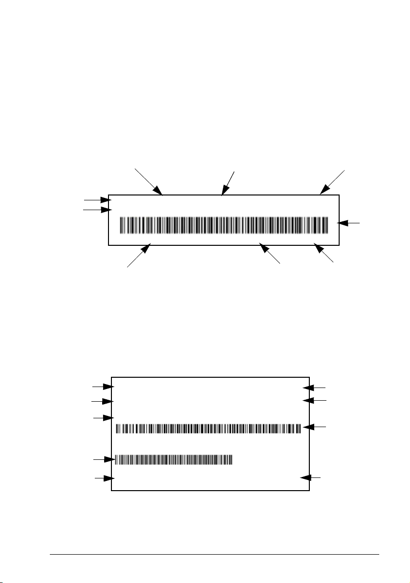
ABB Oy M/N ACS-AP-W S/N:B5320064WU CODE:3AXD50000025964
3AXD5000002 5964B5320064WU RoHS SW: v5.02
FCC ID: 2AFNGAPWSERIES IC:20555-APWSERIES
Type code
ABB Oy
Bar
code
Bar code in readable text
FCC ID
and IC CANADA
numbers
SW version
RoHS marking
MRP code
Serial number
DMS document: 3AXD00000602026
ACS-A-I ABB Oy
6438177306757 SW: v5.80
Type code
ABB Oy
SW version
RoHS marking
MRP code
of the kit
Serial number
of panel inside
the kit
3AUA000008831 RoHS
S/N: A0210001LL
EAN code
Bar code
EAN bar code
EAN number
code
DMS document: 3 AXD00000602026
See Panel-to-PC USB connection (page 63).
RJ-45 connector
The RJ-45 connector is used to electrically connect the control panel to the drive.
Mechanical connection is achieved with the clip on the top.
Type code label on the panel
The type code label on the panel contains revision information. See an example label
below.
Note: FCC ID and IC CANADA numbers are applicable only for ACS-AP-W and ACHAP-W wireless control panels.
Type code label on the panel package
The type code label on the panel package contains revision information. See an
example below.
Page 24

24 Control panel overview
Battery cover
Underneath the battery cover there is a compartment for the battery that powers the
real-time clock of the control panel.
Wireless interface
The ACS-AP-W and ACH-AP-W Assistant control panels with Bluetooth interface
enable wireless interface for ABB drives. The wireless panels are also embedded
with powerful processor and memory that enables faster communication.
The functions of
• ACS-AP-W panel are same with ACS-AP-I and ACS-AP-S panels, and
• ACH-AP-W panel are same with ACH-AP-H panel.
Page 25

Basic operation 25
4
Basic operation
What this chapter contains
The chapter describes the basic operations and components of the user interface. It
also lists the common user tasks and provides instructions to complete the task.
User interface overview
The user interface has the following main components:
Component Description
Home view Used to monitor signals. See Home view (page 22).
Menu Access to most functions of the control panel. See the detailed
description in chapter Functions in the main Menu (page 31).
Options Used to set a reference, change the motor direction, select the drive,
edit Home view pages, and see the fault and warning status. See the
detailed description in chapter Functions in the Options menu
(page 27).
Help Provides information on the current view or menu or on possible
problems associated with it. See Help (page 22).
Faults and warnings View faults and warnings when the drive or control panel experiences
an error. See Fault tracing (page 57).
Page 26

26 Basic operation
Parameters
Assistants
Energy efficiency
Event log
History graphs
Backups
System info
Settings
Home view
Reference
Direction change
Select drive
Edit Home view
Menu
Options
Active faults
Active warnings
Control panel navigation
Use the arrow keys and softkeys for navigation. Follow the choices on the screen.
Note: The menu shown is an example only. The Menu varies based on the drive/
device to which the panel is connected.
Navigation memory
The Assistant control panel has a navigation memory that allows you to backtrack
your steps through the user interface with the arrow keys and . The path you
have last accessed remains in the memory for 10 minutes.
• The left arrow key ( ) moves you backwards in the menu structure.
If you press repeatedly, you return back to the Home view.
• The right arrow key ( ) moves you forward in the menu structure.
If you press repeatedly, you move forward along the path in the menu structure
you had previously accessed.
Page 27

Basic operation 27
Home view
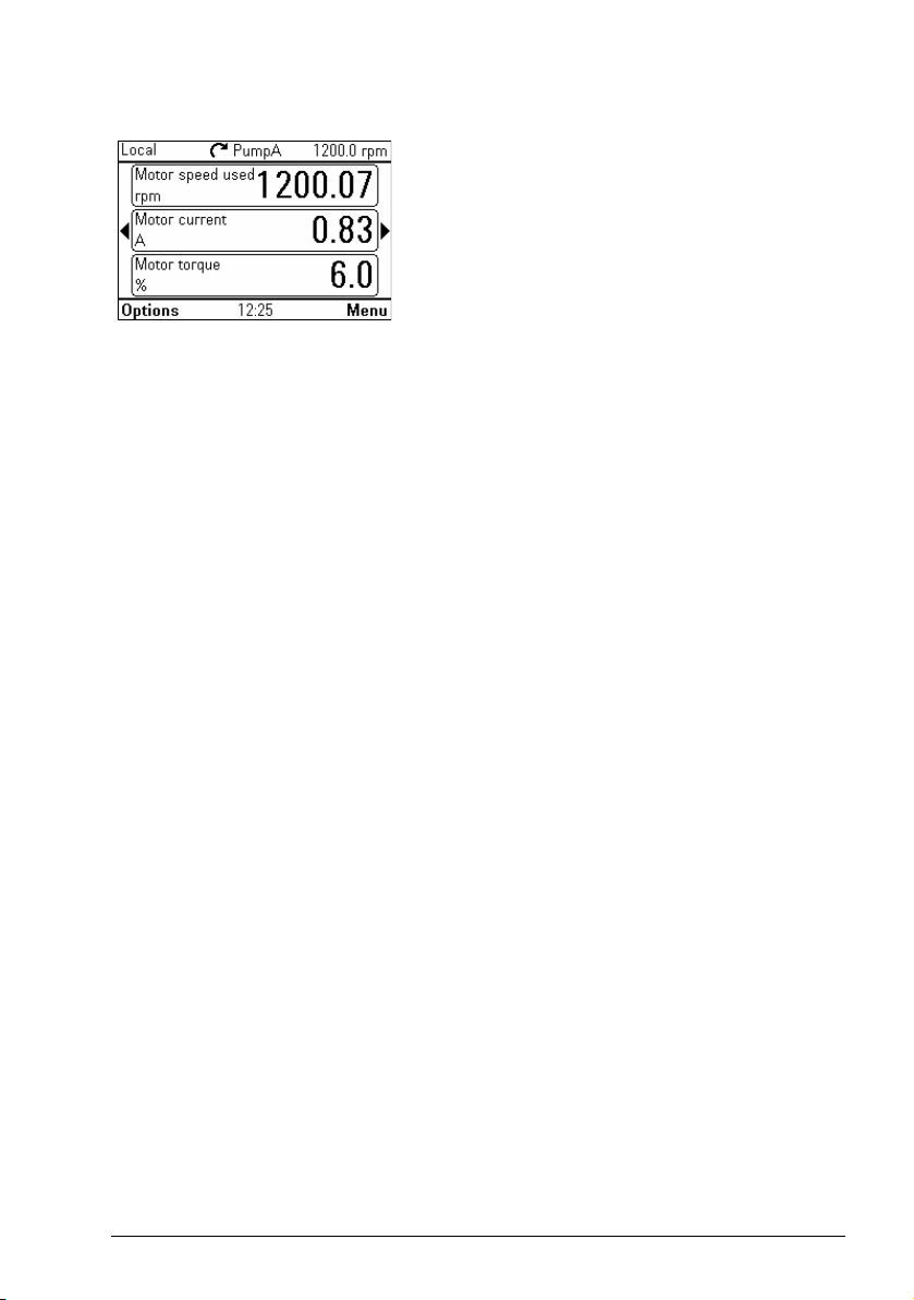
The main view of the control panel is called the Home view. In the Home view, you
can monitor the status of the drive, such as its speed, torque or power. The Home
view has one or more pages, each of which can display up to three signals.
The number of pages and the signals shown on each page are customizable, and the
Home view configuration is saved to the drive whenever you change it. The maximum
total number of signals displayed varies from 9 to 21, depending on the drive. In the
example below, three Home view pages are used, showing different display formats.
Each application macro and user set has a default Home view configuration. When
you select an application macro or restore a user set, the Home view configuration
changes accordingly. There is a default Home view configuration in each drive, which
can be restored in the Primary settings (page 45) or Settings (page 44) menu.
Note: The Menu varies based on the drive/device to which the panel is connected.
The Home view opens automatically when you power up the drive. The Home view is
also displayed from the Options menu or the main Menu if no key is pressed for
10 minutes.
Tip: You can return to the Home view from any view except special screens by
holding down the left softkey
.
Navigating in the Home view
• Use and to move between the different pages of the Home view. The
page numbers are shown while you scroll between pages.
• Use or to adjust the reference (visible in the top right corner). See also
Setting the reference (page 27).
•Press (Menu) to open the main Menu (see Functions in the main Menu
on page 31).
•Press
Options menu on page 27).
(Options) to open the Options menu (see Functions in the
Page 28

28 Basic operation
???
Help
You can open a context-sensitive help page in all menus and views by pressing .
The help page provides information on the use of the current view or menu, or on
possible problems associated with it.
On the help page, you can press again or press (Exit) to exit.
Using
itself. See instructions in section Applicability (page 9).
, you can also view details of control panel type and version in the panel
Page 29

Basic operation 29
Loc/Rem
Common user tasks
The following tables list common user tasks and describes how to complete the task.
See chapters Functions in the main Menu (page 33) and Functions in the Options
menu (page 49) for detailed descriptions of functions in the menus.
Note: The Menu options varies based on the drive/device to which the control panel
is connected.
Basic operation of the drive
Task Actions
Start and stop the drive. In local control, press to start the drive and
to stop the drive.
Set the reference (for example, speed) in
the Home view.
Switch between local and remote control. Press .
Change the direction of motor rotation. In local control, go to Home view, press
Parameters
In local control, go to Options > Reference. Set
the reference with the arrow keys. For detailed
instructions, see Setting the reference (page 50).
(Options) to open the Options menu and select
Direction change.
Task Actions
Choose parameters displayed on the
Favorites list.
View/edit parameters. Go to Menu
Add parameters to the Home view. See Editing the contents of the Home view
Show/hide parameter index and group
numbers.
Restore parameter default value. In the editing mode, press + .
View parameters that differ from
Application Macro defaults.
Go to Menu → Parameters → Favorites →
Edit. See also Editing the list of favorites
(page 35).
→ Parameters → Complete list to
view parameters.
See Editing parameters (page 35) for instructions
on editing parameters.
(page 50).
Press + .
To save the default value, press (Save).
Go to Menu
→ Parameters → Modified.
Page 30

30 Basic operation
???
System information and help
Task Actions
How to get help. Press to open the context-sensitive help.
To view drive information. Go to Menu
To view control panel version. Go to Menu
To view application program
license.
To view Product application
information.
Go to Menu
Go to Menu
→ System info → Drive.
→ System info → Control panel.
→ System info → Licenses.
→ System info → Product application.
Faults and warnings
See Fault tracing (page 57) for detailed information on faults and warnings.
Task Actions
Hide/view an active fault. Faults are automatically displayed. If you hide a fault by
Open help page on a fault. Press to view the help page.
Reset an active fault. Press (Reset) to reset an active fault.
View tripping faults. Go to Menu
Hide/view an active warning. Warnings are automatically displayed. If you hide a warning
Open help page on a warning. Press (How to fix) or to view the help page.
Reset an active warning. Warnings disappear automatically once the condition that
View past warnings and faults. Go to Menu
pressing (Hide), it automatically reappears after 60
seconds of no key presses. You can also view the fault
through Options > Active faults.
→ Event log → Faults.
by pressing (Hide), it automatically reappears if the
warning is still active after 60 seconds of no key presses.
has triggered it goes away.
→ Event log → Other events.
Basic settings and assistants
Task Actions
Adjust backlight brightness. Press and hold , and press or .
Adjust display contrast. Press and hold , and press or .
Change language. Go to Menu
Change time and date, and
related settings.
Launch an assistant. Go to Menu
Go to Menu
launch.
→ Settings → Language.
→ Settings → Date & time.
→ Assistants and select an assistant to
Page 31

Basic operation 31
Backups
Task Actions
Create a backup. See Creating a parameter backup (page 42).
Restore a backup. See Restoring a parameter backup (page 42).
Page 32

32 Basic operation
Page 33

Functions in the main Menu 33
5
Functions in the main Menu
What this chapter contains
The chapter describes the functions in the main Menu.
Menu
All functions of the control panel are accessed
through the Menu which is the main menu of the
user interface. The sub-menus of the Menu are
listed below and they are described in more
detail in the subsequent sections. The submenus depend on the product that is controlled
with the control panel.
The following sub-menus varies based on the drive/device to which the panel is
connected:
Sub-menu Function See page...
Parameters View and edit parameters. 34
Assistants Launch an assistant. 34
Energy eff iciency
Event log View information on faults and warnings. 40
History graphs View the load profile. 41
Backups Save settings in the control panel memory and restore them
System info View information on the drive and options. 43
Settings View and change time and date settings, language, display
Use energy-saving features. 40
41
to the drive.
43
and other settings, and edit texts.
Page 34

34 Functions in the main Menu
Sub-menu Function See page...
Primary settings View and change settings related to motor, PID, fieldbus,
advanced functions, clock, region, and display.
I/O Provides terminal name, number, electrical status and
logical meaning of the drive.
Diagnostics Provides faults and warnings information and helps to
resolve potential problems.
45
46
46
Navigating in the Menu
• Use or to select a menu item.
•Use or (Exit) to go back to the Home view.
•Use
or (Select) to enter the selected sub-menu.
Parameters
In the Parameters menu, you can view and edit
parameters. There are four sub-menus through
which you can access the parameters. In each
sub-menu, the grouping principle of the
parameters is different.
In each sub-menu, you can edit a parameter by
highlighting it and pressing (Edit). Counter
parameters and certain number, text and bit field
parameters are read-only and can be viewed by pressing (View).
Complete list
In the Complete list sub-menu, all parameter
groups are listed in numerical order. If you select a
parameter group, all parameters in that group are
listed and you can view and edit the parameters.
Parameter numbers are always displayed in this
sub-menu.
By function
This functionality is available in a future release.
Page 35

Favorites
In the Favorites sub-menu, only user-selected
parameters are listed. The order is determined by
the parameter number.
Editing the list of favorites
1. Select Edit.
2. Check parameters you want to show on the list
by pressing (Select).
3. Press (Done) to exit and save changes.
Modified
In the Modified sub-menu, only the parameters
whose values differ from the Application Macro
defaults are listed. The order is determined by the
parameter number.
Adding parameters to the Home view
Functions in the main Menu 35
When you view a read-only parameter in the
Parameters menu, you can add the parameter to the Home view.
•Press (Add to view) to open the
Home view in the editing mode then you
can add the parameter to an empty display
slot or replace an existing parameter with it.
•Press (Back) to go back to the
parameter view.
Editing the Home view functions are described in
more detail in Editing the contents of the Home
view (page 50).
Editing parameters
You can edit parameter values with the arrow keys.
1. Press
2. Press (Edit).
3. Use and to change the value.
4. Press (Save) to save the value, or press (Cancel) to exit the
parameter view and discard any changes.
(Select) to select the desired parameter from the list.
Page 36

36 Functions in the main Menu
5. Press + to restore the default value of the parameter (this does not save it).
See the sections below for more information on editing specific parameter types.
Editing numeric parameters
Numeric parameters include parameters with linear numeric values, passcodes, time
and date parameters, durations and exception dates. For numeric parameters with
linear values, the minimum and maximum values are displayed in the bottom left and
right corners of the content area, respectively.
• Use and to highlight digits.
• Use and to change the value.
• Press (Save) to save the value and exit the view.
• To cancel and exit, press (Cancel).
Editing selection list parameters
A selection list consists of mutually exclusive
options, such as the language selection list.
• Use and to move the cursor.
• Press (Save) to select and save the
highlighted option.
• To cancel and exit, press (Cancel).
Some selection list parameters allow you to choose another parameter as its value. In
addition to a preset list of options, you can select a parameter freely, represented by
the selection Other in the list.
Page 37

To select a parameter, follow the instructions:
2
3
4
1
1. Select Other to move to a list of parameter
groups.
2. Select a parameter group to move to a list of
parameters.
3. Depending on the parameter you are editing,
you must select a parameter or an individual bit,
or you may choose either of the two.
• If the right softkey label is Select, you must
select an individual bit as the value of the
parameter you are editing. Press
(Select) to move to a bit selection list.
• If the right softkey label is Save, you can
• If the right softkey label is Save and there is
4. Select a bit if applicable (see the previous step).
Press to invert the selected bit and press
select that parameter as the value of the
parameter you are editing. Press
(Save) to save the selection.
also an arrow on the right hand side of the
selection, you can choose an individual bit or
all the bits in that parameter. Press to
move to a bit selection list. If you want select
all the bits in the parameter, press
(Save) instead.
(Save) to save the selection.
Functions in the main Menu 37
The parameter or bit is now selected as the
parameter value.
Page 38

38 Functions in the main Menu
Editing bit-field parameters
A bit-field parameter is a bit word whose individual
bits can be edited. The labels describe the function
of each bit, and the current state of the bit is shown
as 1 or 0.
• Use and to select a bit.
• To change a bit value, press or .
• To save the bit values and exit, press
(Save).
• To cancel and exit, press (Cancel).
Editing texts
Texts that you can edit with the control panel
include parameter display names in the Home view
and their units, drive names, fault and warning
names, and other customizable notes or names.
• To select the character mode ((lower case /
upper case / numbers / special characters),
press
and then
Now you can start adding characters. The
mode remains selected until you select
another one.
• To add a character, highlight it with
• To remove a letter, press
• Press (Save) to accept the new
setting, or press
to the previous view without making
changes.
unit symbol is highlighted
select the mode with and .
and then press .
.
(Cancel) to go back
Note: The current software version supports only
the English character set (a...z).
Resetting counters
Counters are parameters that measure incremental quantities associated with the
use of the drive such as runtime or energy consumption. Counters are updated
automatically and cannot be edited, but it is possible to reset a counter to zero by
pressing down (Reset) for three seconds.
Note: If a trigger value is defined for the counter, the counter’s progress from zero to
the trigger value is shown as a bar graph.
Page 39

Functions in the main Menu 39
Assistants
In the Assistants menu, you can launch an assistant, which is a sequence of steps
that help you to complete a task, such as setting up the control panel to use with the
drive and the motor, or fixing a fault. You can also generate a QR code, which is an
optical code containing information of the drive. The code can be read with ABB
application and mobile device.
Launching an assistant
1. Use and to highlight the desired
assistant.
2. Press (Select).
3. Follow the instructions on the screen to
complete the task defined by the assistant:
• Use and to select settings.
• To edit a setting, press (Edit or
Select).
• Use and to move between the pages of the assistant. The progress bar
on the upper right corner of the screen indicates the progress.
• To exit the assistant, press (Exit).
Most settings accessed in assistant steps can also be accessed through the main
Menu or the Parameters menu, but the steps the assistants are more user-friendly.
Note: If you used the Assistants menu, complete all steps to save the changes,
otherwise the changes are canceled.
Generating a QR code
1. In the Assistants menu, select QR code using and and press
(Select).
2. Press (Continue).
Page 40

40 Functions in the main Menu
The control panel collects data and generates the code.
Press << or >> to navigate to the next screen.
You can also generate QR code from Menu
System info (page 43).
→ System info → QR code. See
Energy efficiency
In the Energy efficiency menu, you can view and
configure parameters related to energy savings,
such as kWh counters.
Event log
In the Event log menu, you can view information
collected on faults and warnings. Events are
automatically logged. See Fault tracing (page 57)
for more information on faults and warnings.
• Faults sub-menu displays the faults that
are tripped the drive.
• Other events sub-menu displays all other
faults, and warnings and their details.
• Active faults and Active warnings sub-menu displays the faults and
warnings which are active.
Page 41

History graphs
The History graphs menu contains Trends and
Load profile sub-menu.
Trends
This functionality is available in a future release.
Load profile
In the Load profile submenu, you can view and
configure load profiles. The menu contains the
following sub-menus:
• Amplitude logger 1: Opens a Histogram view,
which displays the motor current as a
distribution histogram. This logger cannot be
reset.
• Amplitude logger 2: Opens a Histogram view,
which displays the contents of an amplitude
logger as a distribution histogram. You can
select the signal to be monitored.
• Load profile configuration: Select the signal
to be monitored in Amplitude logger 2.
• Peak value logger: Select a signal to be
monitored by a peak value logger.
Functions in the main Menu 41
For more information on load profiles, see the appropriate firmware manual.
Backups
In the Backups menu, you can save parameter
settings in the control panel memory and restore
parameter settings from a backup to the drive. You
can store up to two backup files on the control
panel.
The assistant panel has a dedicated space for one
automatic backup. An automatic backup is created
two hours after the last parameter change. After completing the backup, the panel
waits for 24 hours before checking if there are additional parameter changes. If there
are, it creates a new backup overwriting the previous one.
You can copy backup files to and from a PC with any file manager application
(example, Windows Explorer).
Page 42

42 Functions in the main Menu
Some of the Backup icons are listed below:
Creating a parameter backup
1. In the Backups menu, select Create backup.
If there is a free backup slot in the control panel,
the following step is skipped.
2. Use and to select one of the existing
backup files, and press Replace.
3. Wait until the backup is completed. An animation
is shown on the control panel during the backup
process. The control panel automatically returns
to the Backups menu.
Note: If the backup process is canceled or
interrupted, the previously saved backup file is not
deleted or damaged. Thus, if you accidentally start a
backup process, you can safely cancel it before its
completion.
Restoring a parameter backup
1. In the Backups menu, select the backup file you want to restore.
2. Select View backup contents and check that it is the correct backup file and that
it is suitable for restoring.
Note: This functionality is available in a future release.
3. Select one of the restore options:
• To restore all settings, select Restore all
parameters.
• To restore a set of parameters, select
Select par restore group and select the
desired parameters from the list, and then
select Restore.
• To select application parameters, select
Select application items and select the desired parameters from the list and
then select Restore.
• To select user parameters sets, select Select user sets and select the desired
user set from the list and then select restore.
Page 43

Functions in the main Menu 43
• To select production data items, select
Select prod. data items and select the
desired production data and then select
restore.
4. Wait until the restore is completed. An
animation is shown on the control panel
during the restoring process.The control panel
automatically returns to the Backups menu.
System info
In the System info menu, you can view information about the drive, control panel,
fieldbus and any installed option modules. You can also generate a QR code that
contains the drive information.
Sub-menu Function
Drive Shows information on the selected
component, such as firmware version, serial
number, type code, device ID number or
date of manufacture.
Note: The content of the view varies
between different drive types.
Control panel Shows information on the hardware and
software version of the control panel.
Page 44

44 Functions in the main Menu
Sub-menu Function
QR code Shows an optical code containing
information of the dr ive. The code can be
read with ABB application and mobile
device.
To generate the QR code, press
(Continue).
The control panel collects data and creates
the code.
Settings
The Settings menu has the following sub-menus:
Sub-menu Function
Language Select different language in the control panel.
Date & time Set date and time, and select their display settings and whether the control
Edit texts Customize editable user interface texts, such as the drive name.
Display settings Set backlight power save on/off and adjust display contrast and brightness.
Reset to defaults Reset settings to their default
panel automatically adjusts the time for daylight savings changes. The time
and date display setting determines how time stamps are formatted.
values.
Erase fault log: This functionality
is available in a future release.
Reset Home view layout: Default
Home view settings are restored.
Reset all parameters: This
functionality is available in a future
release.
Page 45

Functions in the main Menu 45
Sub-menu Function
Show in lists Show or hide the numeric IDs of:
• parameters and groups
• option list items
•bits
• devices in Options
Pass code Enter pass codes into this parameter to activate further access levels (for
example additional parameters).
→ Select drive.
Primary settings
The Primary settings menu has the following sub-menus.
Note: The contents displayed may vary based on the drive/device to which the panel
is connected. The menu shown is only an example.
Sub-menu Function
Macro Set up drive control and reference source by selecting from a set of
predefined wiring configurations.
Drive Adjust drive related settings, such as control location, run permissions,
Motor Adjust motor-related settings, such as control mode, nominal values, ID
Loop controller Set up loop controller settings and actual values. Loop controller is only
Pump and fan
control
Communication Use the drive with a fieldbus.
Start, stop,
reference
Ramps Set up acceleration and deceleration settings.
Limits Set the allowed operating range. This function is intended to protect the
ramps, limits, constants speeds, flying starts references.
run or thermal protection. Note that the settings that are visible depend
on other selections, for example vector or scalar control mode, used
motor type or selected start mode.
used in remote control.
Controls one motor connected to the drive and up to 3 auxiliary motors.
Set up start/stop commands, reference, and related features, such as
constant speeds or run permissions.
motor, connected hardware and mechanics. The drive stays within
these limits, no matter what r eference value it gets.
Page 46

46 Functions in the main Menu
Sub-menu Function
PID Set up the settings and actual values for the process PID controller. PID
is only used in remote control.
Fieldbus To make the protocol configurations easier.
Advanced options/
functions
Clock, region,
display
Reset to defaults Enables you to reset the Home view to its original factory state.
Contains settings for advanced functions, such as triggering or resetting
faults through I/O, or switching between entire set of settings.
Contains settings for language, date and t ime, display (such as
brightness) and settings for changing how information is displayed on
screen.
I/O
In the I/O menu, each row provides terminal name,
number, electrical status and logical meaning of
the drive. Each row also provides a sub-menu that
provides further information on the menu item and
allow you to make changes to the I/O connections.
Diagnostics
The Diagnostics menu provides diagnostic
information, such as faults and warnings and helps
you to resolve potential problems. Use the menu
to make sure that the drive setup is functioning
correctly.
Note: The contents displayed may vary based on
the drive/device to which the panel is connected,
and the menu shown is only an example.
Sub-menu Function
Start, stop,
reference, summary
Limit status Describes any limits currently affecting operation. If the drive is running
Active faults Shows the currently active faults and provides instructions on how to fix
Active warnings Shows the currently active warnings and provides instructions on how to
Active inhibits Shows the currently active inhibits. The drive cannot start. Drive is not
Fault & event log Lists the faults, warnings and other events that have occurred in the
Shows where the drive is currently taking its start, stop commands and
reference. The view is updated in real time. If the drive is not starting or
stopping as expected, or runs at undesired speed, use this view to find
out where the control comes from.
at undesired speed, use this view to find out if any limitations are active.
and reset.
fix and reset.
parameterized correctly.
drive.
Page 47

Functions in the main Menu 47
Sub-menu Function
Fieldbus Provides status information and sent and received data from fieldbus for
troubleshooting.
Load profile Provides status information of load distribution (that is, drive running
time spent on each load level) and peak load levels.
Page 48

48 Functions in the main Menu
Page 49

Functions in the Options menu 49
6
Functions in the Options menu
What this chapter contains
The chapter describes functions in the Options menu.
Options menu
In the Options menu, you can control the settings
related to the Home view.
Note: The contents displayed may vary based on
the drive/device to which the panel is connected.
The menu shown is only an example.
The Options menu has the following sub-menus:
Sub-menu Function
Reference Set the reference value by using
when you save them with a key press
(page 50).
Direction change Change the direction of the motor rotation in local control mode.
Select drive Enable or disable the panel bus. If enabled, view the status of drives in
the panel bus and select which drive to control with the control panel.
See chapter Control of multiple drives (page 53).
Edit Home view Edit the contents of the Home view. See Editing the contents of the
Home view (page 50).
Active faults View an active faults. See chapter Fault tracing (page 57).
Active warnings View an active warnings. See chapter Fault tracing (page 57).
and . The changes take place
. See Setting the reference
Page 50

50 Functions in the Options menu
Loc/Rem
60.0
1200.0 rpm
Two-signal page in editing mode Empty page in editing mode
Softkey labels
and a blinking
cursor indicate
that the
control panel is
Setting the reference
You can change the reference when the drive is in the local control mode. You can
also change the reference in remote control mode if the drive configuration permits it.
Changes take effect when saved with a key press.
1. Press
to switch to the local control mode, if the text in the top left
corner of the display reads Remote.
2. In the Options menu, select Reference.
3. Change the reference by using the following keys:
• Use or to select a digit to edit.
• Use and to change the value of the selected digit.
4. Press
changes. The control panel returns to the Home view.
Tip: To adjust the reference from the Home view, press
or and the reference changes immediately. The
reference value is highlighted when you are changing it. If
you hold down the arrow key, the rate at which the value
changes accelerates.
(Save) to save the reference value, or (Cancel) to discard the
Editing the contents of the Home view
1. In the Options menu, select Edit Home view. This opens the Home view in the
editing mode.
2. In the editing mode, you can add, edit and delete the displayed parameters.
After editing the contents, press (Done) to confirm the changes and to exit
the editing mode and return to the Home view.
3. In the editing mode, use and
Home view.
• To add a new page, navigate to the page that reads Press Add to make a new
screen.
• To edit, add or delete parameters on an existing page, navigate to that page.
to move between the different pages of the
Page 51

Functions in the Options menu 51
2
31
4. Use and to move the cursor highlight.
• To add a new parameter to an existing page,
highlight an area above, between or below
an existing parameter.
• To edit or remove an existing parameter,
highlight that parameter.
5. Press (Edit) to open the Display Slot
menu.
6. Choose a parameter, its display settings and
scaling.
Note: Parameters whose values have textual
representations (such as the names of bit
states) or contain characters other than
numbers (such as dates or durations) are
automatically displayed as text. For these parameters, Display style and
selections pertaining to numeric parameters are not available.
• Parameter: Select the parameter to show in the selected slot. The most
commonly used parameters are listed as presets.
For bit field parameters, you can select either a single bit or the full bit field to add
to the Home view. With individual bits, the bit state is displayed. Full bit fields are
shown in either hexadecimal or binary format.
Note: If Empty is selected, the parameter is removed from the Home view.
• Display style: Select how the signal values are displayed. It is possible to use
different display types on the same page.
• Numeric: The parameter values are displayed as numbers (see figure 1
below). If there is only one parameter on the page, a bar graph is also
displayed.
• Gauge/bar: When there is one parameter on the page, the parameter value is
shown as a dial gauge (see picture 3 below). When there are two or three
parameters on the same page, the value is displayed as a bar graph (see the
slots in figure 2 below).
• Graph 15 minutes, 30 minutes, 1 hour or 24 hours: The parameter value is
displayed as a graph within the selected time frame (see the bottom slot in
picture 2).
Page 52

52 Functions in the Options menu
Scaling with Display signal min/max as and Signal min/max
actual min actual max
actual value
Signal min Signal max
Display signal min as Display signal max as
0
-32767 32768
-3000 6000
-50.00 100.00
display value
Note: The data shown in the graph is not stored in the drive memory, that is, if
you remove or restart the control panel, the data is lost.
• Display decimals: Specifies how many decimals are shown.
• Display name: Enter a custom label to show in the Home view instead of the
parameter name.
• Min and Max: This function depends whether Scale value range is selected or
not:
• Scale value range not selected: Select the minimum and maximum signal
values that are shown on graph displays.
• Scale value range selected: Select the actual values of the parameter that
correspond to Display min as and Display max as (see below).
• Scale value range: Select if you want to specify the value range.
• Display min as and Display max as: Select the minimum and maximum
values shown in the Home view.
This feature allows application-specific scaling to be applied.
If the parameter value is below the minimum or above the maximum, the text
Off the scale is displayed. In the graph format, small arrows are shown instead
to indicate values off the scale.
• Display unit: Customize the unit shown in Home view when scaling is used.
Page 53

Control of multiple drives 53
7
A
CB D
Control of multiple drives
What this chapter contains
The chapter describes how to control several drives with one control panel.
Connecting multiple drives to a control panel
1. Connect the control panel (A) to the first drive (B) in the panel bus.
2. Connect the first drive (C) to the second (D), the second to the third, and so on, by
daisy chaining RJ-45 leads.
Note: Each drive must have a node ID set with drive parameter 49.01 Node ID
number.
The picture shows panel bus example with ACS880-01 drives. The ACX580 and
ACX480 drives have dedicated panel bus adapters with two RJ-45 slots.
Page 54

54 Control of multiple drives
Selecting drive menu
In the Options menu, select Select drive
which lists all the drives connected to the
panel bus and shows their current status. If
panel bus is not enabled, only one drive is
shown.
In the panel bus, If the connection to the
currently selected drive fails, Select drive
menu is shown with the other drive list.
In the Select drive menu, any drives to which the connection is lost are shown in
dimmed text.
Selecting a drive
If there are multiple drives connected to the same panel bus, you can select which
drive to control with the control panel.
1. In the Options menu, select Select drive to open a list of connected drives.
2. Use and to move the cursor. When a drive is highlighted, the green LED on
the drive blinks for one second.
3. Press (Select) to change control to the highlighted drive.
Panel features with multiple drives
Panel views
In a panel bus configuration, the control panel communicates with one drive at a time.
Any information shown on the control panel, such as the status bar or signals in the
Home view pertain to the currently selected drive. Similarly, the control panel stores
data to its memory only from the currently selected drive.
Changes to the Home view configuration and any parameter changes are saved in
the drive. They can be transferred to other drives using the backup feature.
You can view information on other drives in the panel bus and switch to another drive
in the Select drive menu.
The Help page
The content of the Help page is drive-specific, and it always refers to the currently
selected drive.
Page 55

Control of multiple drives 55
Graph data
The data for the graph format in the Home view is stored in the control panel only for
the selected drive. Upon changing the selected drive, any stored graph data is
discarded, and graph data collection begins for the new drive.
History graphs and all related settings (signal selection, horizontal timescale) are
saved in the drive, and the History graphs menu shows always the graphs for the
currently selected drive. Data collection takes places independently in each drive.
Backups
The control panel can store backups from different drives. Conversely, backups from
a drive can be uploaded to another drive.
Customized content
Each drive in the panel bus has its own custom content because all the
customizations are stored in the drive.
Assistants
Assistants are drive-specific, which means that different drives in the panel bus can
have different assistants. However, the assistant framework is the same for all
assistants in all drives.
Faults and warnings with multiple drives
Faults and warnings in the currently selected drive
Faults and warnings in the currently selected drive are shown as normal.
Faults and warnings in other drives
Faults in the other drives in the panel bus appear
as remote faults.
Faults that require a restart look like any other
remote faults. They are shown normally if you
switch to the drive in which the fault has
occurred.
In the Fault view, the keys have the following
functions:
•Press
reappear as with regular faults.
•Press (Switch,) to connect to the faulted drive.
Only active warnings in the selected drive are shown in the control panel. To view
warnings in another drive, you must select that drive in the Select drive menu.
(Hide), to go back to the previous view. The fault view does not
Page 56

56 Control of multiple drives
Page 57

Fault tracing 57
8
Event Icon
Fault activate
Fault reset
Warnin g activat e
Warning deactivate
Pure event activate
Pure event deactivate
Fault tracing
What this chapter contains
This chapter describes how to identify different fault and warning messages that are
shown on the control panel and how to solve problem situations.
Identifying error and warning messages
Faults and warnings are drive states that occur when the drive detects a problem in
its operation. The display message, backlight and LED indications help you to identify
the problem.
Some of the fault and warning icons and their descriptions are mentioned below.
Page 58

58 Fault tracing
Refer to the table below to identify faults and warnings.
Display LED Type
continuous red See Faults (page 59).
blinking red Faults of this type require stopping and
restarting the drive before it continues to
function normally.
See Faults (page 59).
continuous red A fault has occurred in another drive in the
blinking green See Warnings (page 59).
panel bus.
continuous green The connection between the control panel
continuous green The control panel type is not compatible
continuous green The connection between the control panel
and the drive is faulty.
Check that the connection cable is
properly attached.
with the drive you attempt to use it with.
See Compatibility (page 10).
and the drive has been lost.
Check the control panel network
connections.
Select another drive.
Page 59

Fault tracing 59
?
?
Faults
Faults are problems that require your attention before you start the drive again.
Refer the following steps to solve the fault situation:
1. Identify and eliminate the cause of the fault. In the Fault view, you can see the
fault code. Refer to the relevant firmware manual for more information on the
fault.
2. Reset the fault by pressing (Reset) in the Fault view.
In the Fault view, the keys have the following functions:
•Press
back to the previous view. If there is also an active warning, it is displayed instead.
The fault view reappears after 60 seconds if no keys have been pressed.
•Press (Reset) to reset the fault and return to the previous view.
• Press the
to the Fault Diagnostics Assistant which helps you solve the fault situation.
(Hide) or any of the arrow keys to temporarily hide the fault and go
key to open the context-sensitive help. The help page has a shortcut
Warnings
Warnings mean that a possible problem has been detected and may need attention,
and the drive can still run. A warning message disappears once the condition that
triggered it goes away.
•Press
If the warning is still active after 60 seconds of no key presses, the Warning view
reappears automatically.
• Press the
(Hide) to hide the warning message and go back to the previous view.
key to open the context-sensitive help.
Note: If multiple warnings are active, the total number of active warnings is displayed.
Use and to scroll through the warnings.
Page 60

60 Fault tracing
Page 61

Service and maintenance 61
9
1
2
3
Service and maintenance
What this chapter contains
This chapter describes the service and maintenance tasks of the Assistant control
panel.
Removing the control panel cover
It is possible to remove the control panel cover to clean any dust inside the cover or to
change the cover to customize the control panel.
The cover consists of two parts, both of
which can be removed. You do not need
tools to remove the covers.
1. Open the USB connector cover.
2. Remove the lower part of the control
panel cover.
3. Remove the upper part of the cover.
Reinstall the covers in the reverse order.
Cleaning the control panel
Use a soft damp cloth to clean the control
panel. Avoid harsh cleaners which could
scratch the display window.
Page 62

62 Service and maintenance
Cleaning the connectors
Control panel has two connectors, RJ-45 connector (panel back side) and USB
connector (panel front side). Clean outside/around the connectors using suitable
cleaning solution (for example, Isopropyl Alcohol (IPA) solution). Do not use the
cleaning solution to clean inside the connectors.
Replacing the battery
The instructions below describe how to replace the battery that powers the real-time
clock of the control panel.
1. Turn the lid on the back of the control panel counter-clockwise until the lid opens.
2. Remove the battery gently.
3. Replace the battery with a new CR2032 battery. The battery holder has grip nails.
First slide the battery and then press on the other side. The battery will snap in.
4. Make sure that battery polarity shows positive on the upside.
5. Put the lid back and tighten it by turning it clockwise.
6. Dispose of the old battery according to local disposal rules or applicable laws.
Control panel software updates
If the control panel software needs to be updated, contact ABB.
Recycling instructions and environmental information
See the drive related Recycling instructions and environmental information.
Page 63

Panel-to-PC USB connection 63
10
Panel-to-PC USB connection
What this chapter contains
This chapter describes the USB connection between the Assistant control panel and
a PC.
USB connection
The three main functions of the USB connection are:
• The control panel acts as an USB adapter, allowing the PC tool to interact with the
drive. See Connecting a PC tool to a drive through the control panel (page 65).
• It is possible to transfer data (for example, screenshots and backups) between the
control panel and the PC. When connected, the control panel appears as an MTP
(Media Transfer Protocol) device on the PC.
• The USB port is intended for temporary service.
Use the USB connector gently. Otherwise the connector may break.
Pull the USB connector cable correctly. Avoid pulling the cable in side ways
direction.
Page 64

64 Panel-to-PC USB connection
1
2
Rubber
band
Connecting control panel to PC USB
Note: When connected to a PC, the
control panel displays the USB screen
and does not respond to key presses. In
this mode, you can only interact with the
control panel or the drive through the PC
tool.
To connect the control panel to a PC,
1. Open the lid of the USB connector.
2. Plug in a USB cable.
3. Connect to a PC.
The control panel displays the USB
screen.
The USB connector lid is attached to the
panel through a loose rubber band. You
can always connect back the lid to the
band, if it disconnects accidentally.
Page 65

Panel-to-PC USB connection 65
Connecting a PC tool to a drive through the control panel
You can use the control panel to connect an ABB PC tool to the drive. When using the
control panel, you can only access the drive from the PC tool.
1. Install an ABB PC tool to the PC.
2. Connect the control panel to the drive.
3. Connect the control panel to the PC with a USB cable as instructed in Connecting
control panel to PC USB (page 64).
4. If Windows prompts you to install USB drivers, install them as instructed in Drive
composer user’s manual (3AUA0000094606 [English]).
The behavior depends on the current control location of the drive. See Connecting in
local control mode (page 65) and Connecting in remote control mode (page 65).
Connecting in local control mode
When you connect the control panel in local control mode to a PC, local control is
transferred to the PC tool and the control panel displays the USB screen. The drive
retains its present reference and direction.
When you have finished using the PC tool, close the connection through the PC tool
first and then disconnect the USB cable. Local control is transferred back to the
control panel and the drive retains its present reference and direction.
Note: If you disconnect the USB cable before closing the connection, a Local loss
fault is triggered.
Connecting in remote control mode
When you connect the control panel in remote control mode to a PC, the control
panel displays the USB screen and you can only interact with the control panel
through the PC tool. The drive remains in remote control, but you can switch over to
local control using the PC tool.
When you disconnect the PC tool, the control panel exits the USB screen and the
drive resumes its normal operation.
Page 66

66 Panel-to-PC USB connection
Transferring files between the control panel and a PC
1. Connect the control panel to a PC with a USB cable as instructed in Connecting
control panel to PC USB (page 64).
2. If Windows prompts you to install USB drivers, install them as instructed in Drive
composer user’s manual (3AUA0000094606 [English]).
The control panel appears as an MTP device in Windows Explorer.
3. Open ABB Drives Assistant control panel with Windows Explorer, and go to the
directory where the files are stored.
• Screenshots are stored in: ABB Drives Assistant control panel\ABB Drives
Assistant control panel_a\screen
• Backup files are stored in: ABB Drives Assistant control panel\ABB Drives
Assistant control panel_a\backup
4. You can copy files to and from the folders just like any other files with Windows
Explorer.
Page 67

Technical data 67
11
Technical data
What this chapter contains
This chapter contains the technical details of the Assistant control panel.
Connectors
The control panel has the following connectors:
Connector Purpose
RJ-45 female
connector
Type B mini USB
connector
Used for connecting the panel to drive.
• If cable is used, then maximum length should be 100 meters (328 ft.)
•
On a panel bus, the combined maximum length of the panel bu
bles should be 100 meters (328 ft.).
ca
• The panel bus can have a maximum of 32 nodes.
Used for connecting panel to PC. It is intended for temporary service
use (USB 2.0, MTP protocol). The maximum cable length should be
three meters (9.8 ft.).
DMS documents: 3AXD00000587751,
3AXD10000371905
.
s
Display
The control panel has a monochrome, 240 x 160 pixel resolution LCD display with
adjustable backlight and display contrast.
See Basic settings and assistants (page 30).
Page 68

68 Technical data
Battery
At an ambient temperature of 25 °C (77 °F), the change interval of the real-time clock
battery is approximately 10 years.
Battery type CR2032
DMS documents: 3AXD00000587751,
3AXD10000371905
Dimensions and weight
Weight 130 g
Height, width and depth
mm [in.]
Degrees of protection
Degree of protection, attached to a drive IP55
Separately IP20
When control panels are connected in stand-alone to RJ-45 cable IP20
When control panels are connected with USB cable. IP20
Control panel mounted to DPMP-01 IP55
Control panel mounted to DPMP-02 or 03 IP65
When Control panel is not mounted to DPMP-01 or 02 or 03 holder IP20
Control panel mounted to a drive provides the same protection class as the drive unit
itself. For more information, see hardware manual of the drive product.
Page 69

Technical data 69
Materials
Enclosure PC/ABS
Packaging Cardboard
Screen Polycarbonate
Disposal Do not dispose the control panel with municipal waste.
Check the local regulations for disposal of electronic products.
See also, drive related Recycling instructions and environmental information.
Environmental limits
Operation Storage Transportation
Installation site altitude 4000 m (13123 ft.) - -
Air temperature -20 °C to +55 °C
(-4 °F to 131 °F)
Relative humidity 95% (non-condensing)
Temperature inside the panel -20 °C to +70 °C
(-4 °F to 158 °F)
Note: Accuracy of real time clock is not good at very high and very low temperatures.
-40 °C to +70 °C
(-40 °F to 158 °F)
-25 °C to +70 °C
(-13 °F to 158 °F)
DMS documents: 3AXD00000587751,
-40 °C to +70 °C
(-40 °F to 158 °F)
-
3AXD10000371905
IEC compliance
Operation Transportation
Contamination levels
(IEC 60721-3-3, IEC 60721-3-2,
IEC 60721-1-3-1)
Sinusoidal vibration 61800-5-1 ed 2.
Shock class 3M4 in acc. with
Free fall IEC-60068-2-32, drop height
EMC compliance
(EN 61800-3: 2004 +A1: 2012)
3C3
EN 60082-2-6 test Fc (1g)
EN 60062-2-27
1 m. (3.3 ft.)
IEC 61000-4-2, IEC 61000-4-3,
IEC 61000-4-4, IEC 61000-4-6
DMS documents: 3AXD00000587751,
class 2M3 in acc. with
EN 60082-2-6
class 2M2 in acc. with
EN 60082-2-27
-
-
3AXD10000371905
Page 70

70 Technical data
LCD specifications
LCD type FSTN, negative transmissive
Operating temperature -20 °C to +70 °C (-4 °F to 158 °F)
Storage temperature -40 °C to +80 °C (-40 °F to 176 °F)
Transportation temperature -40 °C to +80 °C (-40 °F to 176 °F)
Driver IC UC1698U
ROHS Compliant
General tolerance ± 0.2
Note: Response time of LCD display is slow at/below 0 °C (32 °F).
DMS documents: 3AXD00000587751,
Bluetooth interface
Bluetooth standard Bluetooth 4.0 Dual mode (smart ready),
Bluetooth classic,
Bluetooth LE (low energy)
Certification Bluetooth
Antenna type Internal inverted-F on PCB
Operating frequency 2.4000...2.4835 GHz
Antenna gain Maximum 1.7 dBi
®
Qualified Design
DMS document: 3 AXD10000371905
3AXD10000371905
Bluetooth encryption
Bluetooth classic Bluetooth LE
Encryption
algorithm
Encryption
protocol
Type Symmetrical
Key length 128
Function Key derivation, authentication and payload data encryption
Custom algorithms based on:
•SAFER + for key derivation (called E21 and E22)
• authentication as message authentication code
(c
alled E1)
• payload data encryption (called E0)
E0, E1, E21, E22/ SAFER+ AES
DMS document: 3AXD10000371905
s
(low energy)
AES
Page 71

Technical data 71
FCC and Industry Canada certifications
The following FCC and Industry Canada certifications compliance identification
numbers are valid for ACS-AP-W and ACH-AP-W panels and Bluetooth.
• FCC ID: 2AFNGAPWSERIES
• IC: 20555-APWSERIES
FCC ID: 2AFNGAPWSERIES
The ACS-AP-W and ACH-AP-W wireless assistant control panels comply with part 15
of the FCC rules.
The operation is subject to the following two conditions:
1. The device may not cause harmful interference, an
The device must accept any interference received, including interference that
2.
may cause undesired operation.
Note:
• The wireless panels are tested and found to comply with the limits of a Class A
digital device, pursuant to part 15 of the FCC rules. These limits are designed to
provide reasonable protection against harmful interference when the panels ar
o
perated in a commercial environment.
• The wireless panels will generate, use, and radiate radio frequency energy. If t
s are not installed and used in accordance with the instruction manual, it
panel
may cause harmful interference to radio communications. Operation of thes
panel
s in a residential area is likely to cause harmful interference in which t
user is required to correct the interference at his own expense.
• Modifications not expressly approved by ABB Oy could void the user's authority to
operate the wireless panels.
d
e
he
e
he
IC: 20555-APWSERIES
The ACS-AP-W and ACH-AP-W wireless assistant control panels comply with RSS247, Issue 1, 2015-05. The operation is subject to the following two conditions:
1. The device may not cause interference,
The device must accept any interference, including interference that may caus
2.
undes
ired operation of the device.
Son fonctionnement est sujet aux deux conditions suivantes:
1. le dispositif ne doit pas produire de brouillage préjudiciable, et
2. ce dispositif doit accepter tout brouillage reçu, y compris un brouillage susceptible
de provoquer un fonctionnement indésirable.
and
e
Page 72

72 Technical data
Disclaimers
Generic disclaimer
The manufacturer shall have no obligation hereunder with respect to any product
which (i) has been improperly repaired or altered; (ii) has been subjected to misuse,
negligence or accident; (iii) has been used in a manner contrary to the Manufacturer's
instructions; or (iv) has failed as a result of ordinary wear and tear.
Cybersecurity disclaimer
This product is designed to be connected to and to communicate information and
data via a network interface. It is Customer's sole responsibility to provide and
continuously ensure a secure connection between the product and Customer network
or any other network (as the case may be). Customer shall establish and maintain
any appropriate measures (such as but not limited to the installation of firewalls,
application of authentication measures, encryption of data, installation of anti-virus
programs, etc) to protect the product, the network, its system and the interface
against any kind of security breaches, unauthorized access, interference, intrusion,
leakage and/or theft of data or information. ABB and its affiliates are not liable for
damages and/or losses related to such security breaches, any unauthorized access,
interference, intrusion, leakage and/or theft of data or information.
Page 73

—
Page 74

© Copyright 2018 ABB. All rights reserved.
Specifications subject to change without notice.
3AUA0000 085685 Rev E (EN) 2018-07-11
 Loading...