

Page 1
ABB industrial drives
Firmware manual
ACS880-M04 machinery control program
Page 2

List of related manuals
Drive hardware manuals Code (English)
ACS880-M04 drives hardware manual 3AXD50000028613
*ACS880-01 drives hardware manual 3AUA0000078093
*ACS880-04 drive modules (200 to 710 kW, 300 to 700 hp)
hardware manual
Drive firmware manuals and guides
Adaptive programming application guide 3AXD50000028574
Drive (IEC 61131-3) application programming manual 3AUA0000127808
Option manuals and guides
ACS880-M04 Quick installation guide 3AXD50000032345
ACX-AP-x Assistant control panels user’s manual 3AUA0000085685
ACS-BP-S Basic control panels user’s manual 3AXD50000032527
Drive composer Start-up and maintenance PC tool User’s
manual
Manuals and quick guides for I/O extension modules,
fieldbus adapters, encoder interfaces, etc.
3AUA0000128301
3AUA0000094606
You can find manuals and other product documents in PDF format on the Internet. See section
Document library on the Internet on the inside of the back cover. For manuals not available in the
Document library, contact your local ABB representative.
*A list of links to all manuals applicable to this product is available in the Document library:
Page 3

Firmware manual
ACS880-M04 machinery control program
Table of contents
2016 ABB Oy. All Rights Reserved.
3AXD50000030629 Rev A
EN
EFFECTIVE: 2016-04-11
Page 4

Page 5

Table of contents 5
Table of contents
List of related manuals . . . . . . . . . . . . . . . . . . . . . . . . . . . . . . . . . . . . . . . . . . . . . . . . . . . . . . . 2
1. Introduction to the manual
What this chapter contains . . . . . . . . . . . . . . . . . . . . . . . . . . . . . . . . . . . . . . . . . . . . . . . . . . . 11
Applicability . . . . . . . . . . . . . . . . . . . . . . . . . . . . . . . . . . . . . . . . . . . . . . . . . . . . . . . . . . . . . . . 11
Safety instructions . . . . . . . . . . . . . . . . . . . . . . . . . . . . . . . . . . . . . . . . . . . . . . . . . . . . . . . . . . 11
Target audience . . . . . . . . . . . . . . . . . . . . . . . . . . . . . . . . . . . . . . . . . . . . . . . . . . . . . . . . . . . . 11
Contents of the manual . . . . . . . . . . . . . . . . . . . . . . . . . . . . . . . . . . . . . . . . . . . . . . . . . . . . . . 12
Related documents . . . . . . . . . . . . . . . . . . . . . . . . . . . . . . . . . . . . . . . . . . . . . . . . . . . . . . . . . 12
Terms and abbreviations . . . . . . . . . . . . . . . . . . . . . . . . . . . . . . . . . . . . . . . . . . . . . . . . . . . . . 13
2. Using the control panel
Safety
3. Start-up
Contents of this chapter . . . . . . . . . . . . . . . . . . . . . . . . . . . . . . . . . . . . . . . . . . . . . . . . . . . . . . 17
Before you start . . . . . . . . . . . . . . . . . . . . . . . . . . . . . . . . . . . . . . . . . . . . . . . . . . . . . . . . . . . . 17
Safety . . . . . . . . . . . . . . . . . . . . . . . . . . . . . . . . . . . . . . . . . . . . . . . . . . . . . . . . . . . . . . . . . . . 17
Start-up . . . . . . . . . . . . . . . . . . . . . . . . . . . . . . . . . . . . . . . . . . . . . . . . . . . . . . . . . . . . . . . . . . 18
4. Control locations and operating modes
What this chapter contains . . . . . . . . . . . . . . . . . . . . . . . . . . . . . . . . . . . . . . . . . . . . . . . . . . . 25
Local control vs. external control . . . . . . . . . . . . . . . . . . . . . . . . . . . . . . . . . . . . . . . . . . . . . . . 26
Local control . . . . . . . . . . . . . . . . . . . . . . . . . . . . . . . . . . . . . . . . . . . . . . . . . . . . . . . . . . . 26
External control . . . . . . . . . . . . . . . . . . . . . . . . . . . . . . . . . . . . . . . . . . . . . . . . . . . . . . . . . 27
Operating modes of the drive . . . . . . . . . . . . . . . . . . . . . . . . . . . . . . . . . . . . . . . . . . . . . . . . . 28
Speed control mode . . . . . . . . . . . . . . . . . . . . . . . . . . . . . . . . . . . . . . . . . . . . . . . . . . . . . 29
Torque control mode . . . . . . . . . . . . . . . . . . . . . . . . . . . . . . . . . . . . . . . . . . . . . . . . . . . . . 29
Frequency control mode . . . . . . . . . . . . . . . . . . . . . . . . . . . . . . . . . . . . . . . . . . . . . . . . . . 29
Special control modes . . . . . . . . . . . . . . . . . . . . . . . . . . . . . . . . . . . . . . . . . . . . . . . . . . . . 29
5. Program features
What this chapter contains . . . . . . . . . . . . . . . . . . . . . . . . . . . . . . . . . . . . . . . . . . . . . . . . . . . 31
Drive configuration and programming . . . . . . . . . . . . . . . . . . . . . . . . . . . . . . . . . . . . . . . . . . . 32
Programming via parameters . . . . . . . . . . . . . . . . . . . . . . . . . . . . . . . . . . . . . . . . . . . . . . 32
Adaptive programming . . . . . . . . . . . . . . . . . . . . . . . . . . . . . . . . . . . . . . . . . . . . . . . . . . . 33
Application programming . . . . . . . . . . . . . . . . . . . . . . . . . . . . . . . . . . . . . . . . . . . . . . . . . 35
Control interfaces . . . . . . . . . . . . . . . . . . . . . . . . . . . . . . . . . . . . . . . . . . . . . . . . . . . . . . . . . . 36
Programmable analog inputs . . . . . . . . . . . . . . . . . . . . . . . . . . . . . . . . . . . . . . . . . . . . . . 36
Programmable analog outputs . . . . . . . . . . . . . . . . . . . . . . . . . . . . . . . . . . . . . . . . . . . . . 36
Programmable digital inputs and outputs . . . . . . . . . . . . . . . . . . . . . . . . . . . . . . . . . . . . . 36
Programmable relay outputs . . . . . . . . . . . . . . . . . . . . . . . . . . . . . . . . . . . . . . . . . . . . . . . 37
Programmable I/O extensions . . . . . . . . . . . . . . . . . . . . . . . . . . . . . . . . . . . . . . . . . . . . . . 37
Fieldbus control . . . . . . . . . . . . . . . . . . . . . . . . . . . . . . . . . . . . . . . . . . . . . . . . . . . . . . . . . 38
Page 6

6 Table of contents
Master/follower functionality . . . . . . . . . . . . . . . . . . . . . . . . . . . . . . . . . . . . . . . . . . . . . . . 39
External controller interface . . . . . . . . . . . . . . . . . . . . . . . . . . . . . . . . . . . . . . . . . . . . . . . 44
Motor control . . . . . . . . . . . . . . . . . . . . . . . . . . . . . . . . . . . . . . . . . . . . . . . . . . . . . . . . . . . . . 45
Direct torque control (DTC) . . . . . . . . . . . . . . . . . . . . . . . . . . . . . . . . . . . . . . . . . . . . . . . 45
Reference ramping . . . . . . . . . . . . . . . . . . . . . . . . . . . . . . . . . . . . . . . . . . . . . . . . . . . . . . 45
Constant speeds/frequencies . . . . . . . . . . . . . . . . . . . . . . . . . . . . . . . . . . . . . . . . . . . . . . 46
Critical speeds/frequencies . . . . . . . . . . . . . . . . . . . . . . . . . . . . . . . . . . . . . . . . . . . . . . . 46
Speed controller autotune . . . . . . . . . . . . . . . . . . . . . . . . . . . . . . . . . . . . . . . . . . . . . . . . 47
Oscillation damping . . . . . . . . . . . . . . . . . . . . . . . . . . . . . . . . . . . . . . . . . . . . . . . . . . . . . 50
Rush control . . . . . . . . . . . . . . . . . . . . . . . . . . . . . . . . . . . . . . . . . . . . . . . . . . . . . . . . . . . 51
Encoder support . . . . . . . . . . . . . . . . . . . . . . . . . . . . . . . . . . . . . . . . . . . . . . . . . . . . . . . . 52
Position counter . . . . . . . . . . . . . . . . . . . . . . . . . . . . . . . . . . . . . . . . . . . . . . . . . . . . . . . . 54
Jogging . . . . . . . . . . . . . . . . . . . . . . . . . . . . . . . . . . . . . . . . . . . . . . . . . . . . . . . . . . . . . . 57
Scalar motor control . . . . . . . . . . . . . . . . . . . . . . . . . . . . . . . . . . . . . . . . . . . . . . . . . . . . . 59
Autophasing . . . . . . . . . . . . . . . . . . . . . . . . . . . . . . . . . . . . . . . . . . . . . . . . . . . . . . . . . . . 60
Flux braking . . . . . . . . . . . . . . . . . . . . . . . . . . . . . . . . . . . . . . . . . . . . . . . . . . . . . . . . . . . 63
DC magnetization . . . . . . . . . . . . . . . . . . . . . . . . . . . . . . . . . . . . . . . . . . . . . . . . . . . . . . . 64
Application control . . . . . . . . . . . . . . . . . . . . . . . . . . . . . . . . . . . . . . . . . . . . . . . . . . . . . . . . . 67
Application macros . . . . . . . . . . . . . . . . . . . . . . . . . . . . . . . . . . . . . . . . . . . . . . . . . . . . . . 67
Motor potentiometer . . . . . . . . . . . . . . . . . . . . . . . . . . . . . . . . . . . . . . . . . . . . . . . . . . . . . 67
DC voltage control . . . . . . . . . . . . . . . . . . . . . . . . . . . . . . . . . . . . . . . . . . . . . . . . . . . . . . . . . 68
Overvoltage control . . . . . . . . . . . . . . . . . . . . . . . . . . . . . . . . . . . . . . . . . . . . . . . . . . . . . 68
Undervoltage control (power loss ride-through) . . . . . . . . . . . . . . . . . . . . . . . . . . . . . . . . 68
Voltage control and trip limits . . . . . . . . . . . . . . . . . . . . . . . . . . . . . . . . . . . . . . . . . . . . . . 70
Brake chopper . . . . . . . . . . . . . . . . . . . . . . . . . . . . . . . . . . . . . . . . . . . . . . . . . . . . . . . . . 70
Safety and protections . . . . . . . . . . . . . . . . . . . . . . . . . . . . . . . . . . . . . . . . . . . . . . . . . . . . . . 72
Emergency stop . . . . . . . . . . . . . . . . . . . . . . . . . . . . . . . . . . . . . . . . . . . . . . . . . . . . . . . . 72
Motor thermal protection . . . . . . . . . . . . . . . . . . . . . . . . . . . . . . . . . . . . . . . . . . . . . . . . . 73
Thermal protection of motor cable . . . . . . . . . . . . . . . . . . . . . . . . . . . . . . . . . . . . . . . . . . 76
Other programmable protection functions . . . . . . . . . . . . . . . . . . . . . . . . . . . . . . . . . . . . 76
Automatic fault resets . . . . . . . . . . . . . . . . . . . . . . . . . . . . . . . . . . . . . . . . . . . . . . . . . . . . 78
Diagnostics . . . . . . . . . . . . . . . . . . . . . . . . . . . . . . . . . . . . . . . . . . . . . . . . . . . . . . . . . . . . . . . 79
Fault and warning messages, data logging . . . . . . . . . . . . . . . . . . . . . . . . . . . . . . . . . . . 79
Signal supervision . . . . . . . . . . . . . . . . . . . . . . . . . . . . . . . . . . . . . . . . . . . . . . . . . . . . . . 79
Maintenance timers and counters . . . . . . . . . . . . . . . . . . . . . . . . . . . . . . . . . . . . . . . . . . 79
Energy saving calculators . . . . . . . . . . . . . . . . . . . . . . . . . . . . . . . . . . . . . . . . . . . . . . . . 80
Load analyzer . . . . . . . . . . . . . . . . . . . . . . . . . . . . . . . . . . . . . . . . . . . . . . . . . . . . . . . . . . 80
Miscellaneous . . . . . . . . . . . . . . . . . . . . . . . . . . . . . . . . . . . . . . . . . . . . . . . . . . . . . . . . . . . . . 82
User parameter sets . . . . . . . . . . . . . . . . . . . . . . . . . . . . . . . . . . . . . . . . . . . . . . . . . . . . . 82
Data storage parameters . . . . . . . . . . . . . . . . . . . . . . . . . . . . . . . . . . . . . . . . . . . . . . . . . 82
du/dt filter support . . . . . . . . . . . . . . . . . . . . . . . . . . . . . . . . . . . . . . . . . . . . . . . . . . . . . . 83
6. Application macros
What this chapter contains . . . . . . . . . . . . . . . . . . . . . . . . . . . . . . . . . . . . . . . . . . . . . . . . . . . 85
General . . . . . . . . . . . . . . . . . . . . . . . . . . . . . . . . . . . . . . . . . . . . . . . . . . . . . . . . . . . . . . . . . . 85
Factory macro . . . . . . . . . . . . . . . . . . . . . . . . . . . . . . . . . . . . . . . . . . . . . . . . . . . . . . . . . . . . 86
Default parameter settings for the Factory macro . . . . . . . . . . . . . . . . . . . . . . . . . . . . . . 86
Default control connections for the Factory macro . . . . . . . . . . . . . . . . . . . . . . . . . . . . . . 87
Page 7

Table of contents 7
7. Parameters
What this chapter contains . . . . . . . . . . . . . . . . . . . . . . . . . . . . . . . . . . . . . . . . . . . . . . . . . . . 89
Terms and abbreviations . . . . . . . . . . . . . . . . . . . . . . . . . . . . . . . . . . . . . . . . . . . . . . . . . . . . . 90
Summary of parameter groups . . . . . . . . . . . . . . . . . . . . . . . . . . . . . . . . . . . . . . . . . . . . . . . . 91
Parameter listing . . . . . . . . . . . . . . . . . . . . . . . . . . . . . . . . . . . . . . . . . . . . . . . . . . . . . . . . . . . 94
01 Actual values . . . . . . . . . . . . . . . . . . . . . . . . . . . . . . . . . . . . . . . . . . . . . . . . . . . . . . . . 94
03 Input references . . . . . . . . . . . . . . . . . . . . . . . . . . . . . . . . . . . . . . . . . . . . . . . . . . . . . . 98
04 Warnings and faults . . . . . . . . . . . . . . . . . . . . . . . . . . . . . . . . . . . . . . . . . . . . . . . . . . . 99
05 Diagnostics . . . . . . . . . . . . . . . . . . . . . . . . . . . . . . . . . . . . . . . . . . . . . . . . . . . . . . . . . 106
06 Control and status words . . . . . . . . . . . . . . . . . . . . . . . . . . . . . . . . . . . . . . . . . . . . . . 108
07 System info . . . . . . . . . . . . . . . . . . . . . . . . . . . . . . . . . . . . . . . . . . . . . . . . . . . . . . . . 120
10 Standard DI, RO . . . . . . . . . . . . . . . . . . . . . . . . . . . . . . . . . . . . . . . . . . . . . . . . . . . . . 122
11 Standard DIO, FI, FO . . . . . . . . . . . . . . . . . . . . . . . . . . . . . . . . . . . . . . . . . . . . . . . . . 130
12 Standard AI . . . . . . . . . . . . . . . . . . . . . . . . . . . . . . . . . . . . . . . . . . . . . . . . . . . . . . . . 136
13 Standard AO . . . . . . . . . . . . . . . . . . . . . . . . . . . . . . . . . . . . . . . . . . . . . . . . . . . . . . . 141
14 I/O extension module 1 . . . . . . . . . . . . . . . . . . . . . . . . . . . . . . . . . . . . . . . . . . . . . . . 147
15 I/O extension module 2 . . . . . . . . . . . . . . . . . . . . . . . . . . . . . . . . . . . . . . . . . . . . . . . 169
19 Operation mode . . . . . . . . . . . . . . . . . . . . . . . . . . . . . . . . . . . . . . . . . . . . . . . . . . . . . 173
20 Start/stop/direction . . . . . . . . . . . . . . . . . . . . . . . . . . . . . . . . . . . . . . . . . . . . . . . . . . . 176
21 Start/stop mode . . . . . . . . . . . . . . . . . . . . . . . . . . . . . . . . . . . . . . . . . . . . . . . . . . . . . 188
22 Speed reference selection . . . . . . . . . . . . . . . . . . . . . . . . . . . . . . . . . . . . . . . . . . . . . 198
23 Speed reference ramp . . . . . . . . . . . . . . . . . . . . . . . . . . . . . . . . . . . . . . . . . . . . . . . . 209
24 Speed reference conditioning . . . . . . . . . . . . . . . . . . . . . . . . . . . . . . . . . . . . . . . . . . 217
25 Speed control . . . . . . . . . . . . . . . . . . . . . . . . . . . . . . . . . . . . . . . . . . . . . . . . . . . . . . . 220
26 Torque reference chain . . . . . . . . . . . . . . . . . . . . . . . . . . . . . . . . . . . . . . . . . . . . . . . 234
28 Frequency reference chain . . . . . . . . . . . . . . . . . . . . . . . . . . . . . . . . . . . . . . . . . . . . 243
30 Limits . . . . . . . . . . . . . . . . . . . . . . . . . . . . . . . . . . . . . . . . . . . . . . . . . . . . . . . . . . . . . 255
31 Fault functions . . . . . . . . . . . . . . . . . . . . . . . . . . . . . . . . . . . . . . . . . . . . . . . . . . . . . . 263
32 Supervision . . . . . . . . . . . . . . . . . . . . . . . . . . . . . . . . . . . . . . . . . . . . . . . . . . . . . . . . 276
33 Generic timer & counter . . . . . . . . . . . . . . . . . . . . . . . . . . . . . . . . . . . . . . . . . . . . . . . 280
35 Motor thermal protection . . . . . . . . . . . . . . . . . . . . . . . . . . . . . . . . . . . . . . . . . . . . . . 290
36 Load analyzer . . . . . . . . . . . . . . . . . . . . . . . . . . . . . . . . . . . . . . . . . . . . . . . . . . . . . . . 304
43 Brake chopper . . . . . . . . . . . . . . . . . . . . . . . . . . . . . . . . . . . . . . . . . . . . . . . . . . . . . . 308
44 Mechanical brake control . . . . . . . . . . . . . . . . . . . . . . . . . . . . . . . . . . . . . . . . . . . . . . 310
45 Energy efficiency . . . . . . . . . . . . . . . . . . . . . . . . . . . . . . . . . . . . . . . . . . . . . . . . . . . . 316
46 Monitoring/scaling settings . . . . . . . . . . . . . . . . . . . . . . . . . . . . . . . . . . . . . . . . . . . . . 320
47 Data storage . . . . . . . . . . . . . . . . . . . . . . . . . . . . . . . . . . . . . . . . . . . . . . . . . . . . . . . . 324
49 Panel port communication . . . . . . . . . . . . . . . . . . . . . . . . . . . . . . . . . . . . . . . . . . . . . 327
50 Fieldbus adapter (FBA) . . . . . . . . . . . . . . . . . . . . . . . . . . . . . . . . . . . . . . . . . . . . . . . 330
51 FBA A settings . . . . . . . . . . . . . . . . . . . . . . . . . . . . . . . . . . . . . . . . . . . . . . . . . . . . . . 341
52 FBA A data in . . . . . . . . . . . . . . . . . . . . . . . . . . . . . . . . . . . . . . . . . . . . . . . . . . . . . . . 342
53 FBA A data out . . . . . . . . . . . . . . . . . . . . . . . . . . . . . . . . . . . . . . . . . . . . . . . . . . . . . . 343
54 FBA B settings . . . . . . . . . . . . . . . . . . . . . . . . . . . . . . . . . . . . . . . . . . . . . . . . . . . . . . 344
55 FBA B data in . . . . . . . . . . . . . . . . . . . . . . . . . . . . . . . . . . . . . . . . . . . . . . . . . . . . . . . 345
56 FBA B data out . . . . . . . . . . . . . . . . . . . . . . . . . . . . . . . . . . . . . . . . . . . . . . . . . . . . . . 346
58 Embedded fieldbus . . . . . . . . . . . . . . . . . . . . . . . . . . . . . . . . . . . . . . . . . . . . . . . . . . 346
60 DDCS communication . . . . . . . . . . . . . . . . . . . . . . . . . . . . . . . . . . . . . . . . . . . . . . . . 357
61 D2D and DDCS transmit data . . . . . . . . . . . . . . . . . . . . . . . . . . . . . . . . . . . . . . . . . . 366
62 D2D and DDCS receive data . . . . . . . . . . . . . . . . . . . . . . . . . . . . . . . . . . . . . . . . . . . 370
90 Feedback selection . . . . . . . . . . . . . . . . . . . . . . . . . . . . . . . . . . . . . . . . . . . . . . . . . . 379
Page 8

8 Table of contents
91 Encoder module settings . . . . . . . . . . . . . . . . . . . . . . . . . . . . . . . . . . . . . . . . . . . . . . 391
92 Encoder 1 configuration . . . . . . . . . . . . . . . . . . . . . . . . . . . . . . . . . . . . . . . . . . . . . . 395
93 Encoder 2 configuration . . . . . . . . . . . . . . . . . . . . . . . . . . . . . . . . . . . . . . . . . . . . . . 403
95 HW configuration . . . . . . . . . . . . . . . . . . . . . . . . . . . . . . . . . . . . . . . . . . . . . . . . . . . . 406
96 System . . . . . . . . . . . . . . . . . . . . . . . . . . . . . . . . . . . . . . . . . . . . . . . . . . . . . . . . . . . 410
97 Motor control . . . . . . . . . . . . . . . . . . . . . . . . . . . . . . . . . . . . . . . . . . . . . . . . . . . . . . . 419
98 User motor parameters . . . . . . . . . . . . . . . . . . . . . . . . . . . . . . . . . . . . . . . . . . . . . . . 423
99 Motor data . . . . . . . . . . . . . . . . . . . . . . . . . . . . . . . . . . . . . . . . . . . . . . . . . . . . . . . . . 425
200 Safety . . . . . . . . . . . . . . . . . . . . . . . . . . . . . . . . . . . . . . . . . . . . . . . . . . . . . . . . . . . 433
8. Additional parameter data
What this chapter contains . . . . . . . . . . . . . . . . . . . . . . . . . . . . . . . . . . . . . . . . . . . . . . . . . . 435
Terms and abbreviations . . . . . . . . . . . . . . . . . . . . . . . . . . . . . . . . . . . . . . . . . . . . . . . . . . . 435
Fieldbus addresses . . . . . . . . . . . . . . . . . . . . . . . . . . . . . . . . . . . . . . . . . . . . . . . . . . . . . . . 436
Parameter groups 1…9 . . . . . . . . . . . . . . . . . . . . . . . . . . . . . . . . . . . . . . . . . . . . . . . . . . . . 437
Parameter groups 10…99 . . . . . . . . . . . . . . . . . . . . . . . . . . . . . . . . . . . . . . . . . . . . . . . . . . 442
9. Fault tracing
What this chapter contains . . . . . . . . . . . . . . . . . . . . . . . . . . . . . . . . . . . . . . . . . . . . . . . . . . 479
Safety . . . . . . . . . . . . . . . . . . . . . . . . . . . . . . . . . . . . . . . . . . . . . . . . . . . . . . . . . . . . . . . . . . 479
Indications . . . . . . . . . . . . . . . . . . . . . . . . . . . . . . . . . . . . . . . . . . . . . . . . . . . . . . . . . . . . . . 479
Warnings and faults . . . . . . . . . . . . . . . . . . . . . . . . . . . . . . . . . . . . . . . . . . . . . . . . . . . . 479
Pure events . . . . . . . . . . . . . . . . . . . . . . . . . . . . . . . . . . . . . . . . . . . . . . . . . . . . . . . . . . 480
Editable messages . . . . . . . . . . . . . . . . . . . . . . . . . . . . . . . . . . . . . . . . . . . . . . . . . . . . . 480
Warning/fault history and analysis . . . . . . . . . . . . . . . . . . . . . . . . . . . . . . . . . . . . . . . . . . . . 480
Event logs . . . . . . . . . . . . . . . . . . . . . . . . . . . . . . . . . . . . . . . . . . . . . . . . . . . . . . . . . . . 480
Other data loggers . . . . . . . . . . . . . . . . . . . . . . . . . . . . . . . . . . . . . . . . . . . . . . . . . . . . . 481
Parameters that contain warning/fault information . . . . . . . . . . . . . . . . . . . . . . . . . . . . . 481
QR Code generation for mobile service application . . . . . . . . . . . . . . . . . . . . . . . . . . . . . . . 482
Warning messages . . . . . . . . . . . . . . . . . . . . . . . . . . . . . . . . . . . . . . . . . . . . . . . . . . . . . . . . 483
Fault messages . . . . . . . . . . . . . . . . . . . . . . . . . . . . . . . . . . . . . . . . . . . . . . . . . . . . . . . . . . 503
10. Fieldbus control through the embedded fieldbus interface (EFB)
What this chapter contains . . . . . . . . . . . . . . . . . . . . . . . . . . . . . . . . . . . . . . . . . . . . . . . . . . 527
System overview . . . . . . . . . . . . . . . . . . . . . . . . . . . . . . . . . . . . . . . . . . . . . . . . . . . . . . . . . 527
Connecting the fieldbus to the drive . . . . . . . . . . . . . . . . . . . . . . . . . . . . . . . . . . . . . . . . . . . 528
Setting up the embedded fieldbus interface . . . . . . . . . . . . . . . . . . . . . . . . . . . . . . . . . . . . . 529
Setting the drive control parameters . . . . . . . . . . . . . . . . . . . . . . . . . . . . . . . . . . . . . . . . . . 530
Basics of the embedded fieldbus interface . . . . . . . . . . . . . . . . . . . . . . . . . . . . . . . . . . . . . . 533
Control word and Status word . . . . . . . . . . . . . . . . . . . . . . . . . . . . . . . . . . . . . . . . . . . . 534
References . . . . . . . . . . . . . . . . . . . . . . . . . . . . . . . . . . . . . . . . . . . . . . . . . . . . . . . . . . . 534
Actual values . . . . . . . . . . . . . . . . . . . . . . . . . . . . . . . . . . . . . . . . . . . . . . . . . . . . . . . . . 534
Data input/outputs . . . . . . . . . . . . . . . . . . . . . . . . . . . . . . . . . . . . . . . . . . . . . . . . . . . . . 534
Register addressing . . . . . . . . . . . . . . . . . . . . . . . . . . . . . . . . . . . . . . . . . . . . . . . . . . . . 535
About the control profiles . . . . . . . . . . . . . . . . . . . . . . . . . . . . . . . . . . . . . . . . . . . . . . . . . . . 536
The ABB Drives profile . . . . . . . . . . . . . . . . . . . . . . . . . . . . . . . . . . . . . . . . . . . . . . . . . . . . . 537
Control Word . . . . . . . . . . . . . . . . . . . . . . . . . . . . . . . . . . . . . . . . . . . . . . . . . . . . . . . . . 537
Status Word . . . . . . . . . . . . . . . . . . . . . . . . . . . . . . . . . . . . . . . . . . . . . . . . . . . . . . . . . . 539
Page 9

Table of contents 9
State transition diagram . . . . . . . . . . . . . . . . . . . . . . . . . . . . . . . . . . . . . . . . . . . . . . . . . 540
References . . . . . . . . . . . . . . . . . . . . . . . . . . . . . . . . . . . . . . . . . . . . . . . . . . . . . . . . . . . 541
Actual values . . . . . . . . . . . . . . . . . . . . . . . . . . . . . . . . . . . . . . . . . . . . . . . . . . . . . . . . . . 542
Modbus holding register addresses . . . . . . . . . . . . . . . . . . . . . . . . . . . . . . . . . . . . . . . . 543
The Transparent profile . . . . . . . . . . . . . . . . . . . . . . . . . . . . . . . . . . . . . . . . . . . . . . . . . . . . . 544
Modbus function codes . . . . . . . . . . . . . . . . . . . . . . . . . . . . . . . . . . . . . . . . . . . . . . . . . . . . . 545
Exception codes . . . . . . . . . . . . . . . . . . . . . . . . . . . . . . . . . . . . . . . . . . . . . . . . . . . . . . . . . . 546
Coils (0xxxx reference set) . . . . . . . . . . . . . . . . . . . . . . . . . . . . . . . . . . . . . . . . . . . . . . . . . . 547
Discrete inputs (1xxxx reference set) . . . . . . . . . . . . . . . . . . . . . . . . . . . . . . . . . . . . . . . . . . 548
Error code registers (holding registers 400090…400100) . . . . . . . . . . . . . . . . . . . . . . . . . . . 550
11. Fieldbus control through a fieldbus adapter
What this chapter contains . . . . . . . . . . . . . . . . . . . . . . . . . . . . . . . . . . . . . . . . . . . . . . . . . . 551
System overview . . . . . . . . . . . . . . . . . . . . . . . . . . . . . . . . . . . . . . . . . . . . . . . . . . . . . . . . . . 551
Basics of the fieldbus control interface . . . . . . . . . . . . . . . . . . . . . . . . . . . . . . . . . . . . . . . . . 554
Control word and Status word . . . . . . . . . . . . . . . . . . . . . . . . . . . . . . . . . . . . . . . . . . . . . 555
References . . . . . . . . . . . . . . . . . . . . . . . . . . . . . . . . . . . . . . . . . . . . . . . . . . . . . . . . . . . 556
Actual values . . . . . . . . . . . . . . . . . . . . . . . . . . . . . . . . . . . . . . . . . . . . . . . . . . . . . . . . . . 557
Contents of the fieldbus Control word . . . . . . . . . . . . . . . . . . . . . . . . . . . . . . . . . . . . . . . 558
Contents of the fieldbus Status word . . . . . . . . . . . . . . . . . . . . . . . . . . . . . . . . . . . . . . . 559
The state diagram . . . . . . . . . . . . . . . . . . . . . . . . . . . . . . . . . . . . . . . . . . . . . . . . . . . . . . 560
Setting up the drive for fieldbus control . . . . . . . . . . . . . . . . . . . . . . . . . . . . . . . . . . . . . . . . . 561
Parameter setting example: FPBA (PROFIBUS DP) . . . . . . . . . . . . . . . . . . . . . . . . . . . 562
12. Control chain diagrams
What this chapter contains . . . . . . . . . . . . . . . . . . . . . . . . . . . . . . . . . . . . . . . . . . . . . . . . . . 565
Speed reference source selection I . . . . . . . . . . . . . . . . . . . . . . . . . . . . . . . . . . . . . . . . . . . . 566
Speed reference source selection II . . . . . . . . . . . . . . . . . . . . . . . . . . . . . . . . . . . . . . . . . . . 567
Speed reference ramping and shaping . . . . . . . . . . . . . . . . . . . . . . . . . . . . . . . . . . . . . . . . . 568
Motor feedback configuration . . . . . . . . . . . . . . . . . . . . . . . . . . . . . . . . . . . . . . . . . . . . . . . . 569
Load feedback and position counter configuration . . . . . . . . . . . . . . . . . . . . . . . . . . . . . . . . 570
Speed error calculation . . . . . . . . . . . . . . . . . . . . . . . . . . . . . . . . . . . . . . . . . . . . . . . . . . . . . 571
Speed controller . . . . . . . . . . . . . . . . . . . . . . . . . . . . . . . . . . . . . . . . . . . . . . . . . . . . . . . . . . 572
Torque reference source selection and modification . . . . . . . . . . . . . . . . . . . . . . . . . . . . . . . 573
Operating mode selection . . . . . . . . . . . . . . . . . . . . . . . . . . . . . . . . . . . . . . . . . . . . . . . . . . . 574
Reference selection for torque controller . . . . . . . . . . . . . . . . . . . . . . . . . . . . . . . . . . . . . . . . 575
Torque limitation . . . . . . . . . . . . . . . . . . . . . . . . . . . . . . . . . . . . . . . . . . . . . . . . . . . . . . . . . . 576
Torque controller . . . . . . . . . . . . . . . . . . . . . . . . . . . . . . . . . . . . . . . . . . . . . . . . . . . . . . . . . . 577
Frequency reference selection . . . . . . . . . . . . . . . . . . . . . . . . . . . . . . . . . . . . . . . . . . . . . . . 578
Frequency reference modification . . . . . . . . . . . . . . . . . . . . . . . . . . . . . . . . . . . . . . . . . . . . . 579
Master/Follower communication I (Master) . . . . . . . . . . . . . . . . . . . . . . . . . . . . . . . . . . . . . . 580
Master/Follower communication II (Follower) . . . . . . . . . . . . . . . . . . . . . . . . . . . . . . . . . . . . 581
Further information
Product and service inquiries . . . . . . . . . . . . . . . . . . . . . . . . . . . . . . . . . . . . . . . . . . . . . . . . 583
Product training . . . . . . . . . . . . . . . . . . . . . . . . . . . . . . . . . . . . . . . . . . . . . . . . . . . . . . . . . . . 583
Providing feedback on ABB Drives manuals . . . . . . . . . . . . . . . . . . . . . . . . . . . . . . . . . . . . . 583
Document library on the Internet . . . . . . . . . . . . . . . . . . . . . . . . . . . . . . . . . . . . . . . . . . . . . . 583
Page 10

10 Table of contents
Page 11

Introduction to the manual 11
1
Introduction to the manual
What this chapter contains
This chapter describes the contents of the manual. It also contains information on the
compatibility, safety and intended audience.
Applicability
This manual applies to ACS880-M04 machinery control program version 2.4x.
The firmware version of the control program is visible in parameter 07.05 Firmware
version, or the System info in the main menu on the drive control panel.
Safety instructions
Obey all safety instructions delivered with the drive.
• Read the complete safety instructions before you install, commission, or use
the drive. The complete safety instructions are delivered with the drive as part of
the Hardware manual as a separate document.
• Read the firmware function-specific warnings and notes before changing
parameter values. These warnings and notes are included in the parameter
descriptions presented in chapter Parameters.
Target audience
This manual is intended for people who design, commission, or operate the drive
system.
Page 12

12 Introduction to the manual
Contents of the manual
This manual contains the following chapters:
• Using the control panel provides basic instructions for the use of the control panel.
• Control locations and operating modes describes the control locations and
operating modes of the drive.
• Program features contains descriptions of the features of the ACS880-M04
primary control program.
• Application macros contains a short description of each macro together with a
connection diagram. Macros are pre-defined applications which will save the user
time when configuring the drive.
• Parameters describes the parameters used to program the drive.
• Additional parameter data contains further information on the parameters.
• Fault tracing lists the warning and fault messages with possible causes and
remedies.
• Fieldbus control through the embedded fieldbus interface (EFB) describes the
communication to and from a fieldbus network using the embedded fieldbus
interface of the drive.
• Fieldbus control through a fieldbus adapter describes the communication to and
from a fieldbus network using an optional fieldbus adapter module.
• Control chain diagrams showing the parameter structure within the drive.
Related documents
Note: A quick start-up sequence for a speed control application is provided by
ACS880-M04 Quick installation and start-up guide (3AXD50000032345), delivered
with the drive.
See the List of related manuals on the inside of front cover.
Page 13

Terms and abbreviations
Introduction to the manual 13
Term /
abbreviation
ACS800 A product family of ABB drives
ACS-AP-I,
ACS-AP-W
ACS-BP-S Basic control panel
AI Analog input; interface for analog input signals
AO Analog output; interface for analog output signals
DC link DC circuit between rectifier and inverter
DDCS Distributed drives communication system; a protocol used in communication
DI Digital input; interface for digital input signals
DIO Digital input/output; interface that can be used as a digital input or output
DO Digital output; interface for digital output signals
Drive Frequency converter for controlling AC motors. The drive consists of a rectifier
Definition
Assistant control panel. Type of control panels used with ACS880-M04 drives
between ABB drive equipment
and an inverter connected together by the DC link. In drives up to
approximately 500 kW, these are integrated into a single module (drive
module). Larger drives typically consist of separate supply and inverter units.
The ACS880-M04 primary control program is used to control the inverter part
of the drive.
DriveBus A communication link used by, for example, ABB controllers. ACS880-M04
drives can be connected to the DriveBus link of the controller.
DTC Direct torque control. See page 45.
FBA Fieldbus adapter
FCAN-01 Optional CANopen adapter
FCNA-01 Optional ControlNet adapter
FDCO-0x Optional DDCS communication module
FDNA-01 Optional DeviceNet adapter
FECA-01 Optional EtherCAT® adapter
FEN-01 Optional TTL encoder interface module
FEN-11 Optional absolute encoder interface module
FEN-21 Optional resolver interface module
FEN-31 Optional HTL encoder interface module
FENA-11 Optional Ethernet/IP, Modbus/TCP and PROFINET IO adapter
FENA-21 Optional dual-port Ethernet/IP, Modbus/TCP and PROFINET IO adapter
FEPL-02 Optional POWERLINK adapter
FIO-01 Optional digital I/O extension module
FIO-11 Optional analog I/O extension module
FPBA-01 Optional PROFIBUS DP adapter
FSCA-01 Optional Modbus/RTU adapter
Page 14

14 Introduction to the manual
Term/
Definition
abbreviation
FSO-xx Optional safety functions module
HTL High-threshold logic
ID run Motor identification run. During the identification run, the drive will identify the
characteristics of the motor for optimum motor control.
IGBT Insulated gate bipolar transistor; a voltage-controlled semiconductor type
widely used in inverters and IGBT supply units due to their easy controllability
and high switching frequency
Inverter unit In large drives (> 500 kW approx.), the part of the drive that converts DC to
AC for the motor. Consists of one or more inverter modules and their auxiliary
components.
I/O Input/Output
ModuleBus A communication link used by, for example, ABB controllers. ACS880-M04
drives can be connected to the optical ModuleBus link of the controller.
Motor-side
See inverter unit.
converter
Network
control
With fieldbus protocols based on the Common Industrial Protocol (CIP
such as DeviceNet and Ethernet/IP, denotes the control of the drive using the
TM
),
Net Ctrl and Net Ref objects of the ODVA AC/DC Drive Profile. For more
information, see www.odva.org
, and the following manuals:
• FDNA-01 DeviceNet adapter module User’s manual (3AFE68573360
[English]), and
• FENA-01/-11 Ethernet adapter module User’s manual (3AUA0000093568
[English]).
Parameter User-adjustable operation instruction to the drive, or signal measured or
calculated by the drive
PLC Programmable logic controller
Power unit Contains the power electronics and power connections of the drive (or inverter
module). The drive control unit is connected to the power unit.
PTC Positive temperature coefficient
RFG Ramp function generator.
RO Relay output; interface for a digital output signal. Implemented with a relay.
SSI Synchronous serial interface
STO Safe torque off
TTL Transistor-transistor logic
UPS Uninterruptible power supply; power supply equipment with battery to
maintain output voltage during power failure
ZCU Type of control unit used in ACS880-M04 drives (primarily in drive modules, or
inverter/supply units consisting of a single power module). Consists of an I/O
board built into a plastic housing.
Depending on the type of hardware, the control unit may be integrated into or
fitted onto the drive/inverter module, or installed separately.
Page 15

Using the control panel 15
2
Using the control panel
Refer to
• ACX-AP-x assistant control panels user’s manual (3AUA0000085685 [English])
and
• ACS-BP-S assistant control panels user’s manual (3AXD50000032527 [English]).
Page 16

16 Using the control panel
Page 17

3
Start-up
Start-up 17
Contents of this chapter
This chapter describes the basic start-up sequence of an ACS880-M04 machinery
drive.
In this guide, the drive is set up using the ACS-AP-I control panel. The start-up
sequence can also be carried out using the Drive composer PC tool.
Before you start
Make sure the drive is mechanically and electrically installed as described in the
Quick installation guide and/or Hardware manual.
Safety
WARNING! Follow all safety instructions of the drive. Only qualified electricians are
allowed to start up the drive. Never work on the drive, the brake chopper circuit, the
motor cable or the motor when power is applied to the drive. Always make sure by
measuring that no voltage is actually present.
WARNING! Make sure that the machinery into which the drive with brake
control function is integrated fulfills the personnel safety regulations.
Note that the frequency converter (a Complete Drive Module or a Basic Drive
Module, as defined in IEC 61800-2), is not considered as a safety device mentioned
in the European Machinery Directive and related harmonized standards. Thus, the
personnel safety of the complete machinery must not be based on a specific
frequency converter feature (such as the brake control function), but it has to be
implemented as defined in the application specific regulations.
Page 18
18 Start-up
Remote 0.0 rpm
0.00
0.00
Motor torque
%
0.0
Motor current
A
Motor speed used
rpm
Options
12:34
Menu
ACS880
Remote 0.0 rpm
Menu
Parameters
Assistants
Energy efficiency
Event log
Exit
12:34
Select
Start-up
Safety
WARNING! Obey all safety instructions for the drive. Only qualified electricians are
allowed to start up the drive.
Check the installation. See the installation checklist in the Hardware manual.
Check that the starting of the motor does not cause any danger.
De-couple the driven machine if
• there is a risk of damage in case of an incorrect direction of rotation, or
•a Normal ID run is required during the drive start-up, when the load torque is higher
than 20% or the machinery is not able to withstand the nominal torque transient during
the ID run.
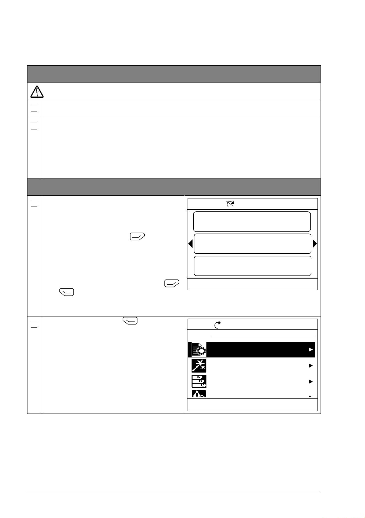
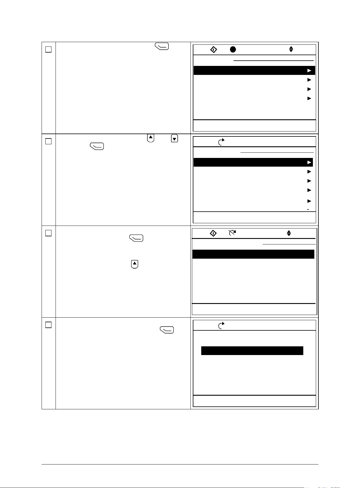
1 – Power-up, date and time settings
Power up the drive.
Note: It is normal that warning messages
appear at various points along the start-up
process. To hide a message and to resume
the start-up process, press .
Hide any warnings now to enter the Home
view (shown on the right).
The two commands at the bottom of the
display (in this case, Options and Menu),
show the functions of the two softkeys
and located below the display. The
commands assigned to the softkeys vary
depending on the context.
In the Home view, press (Menu).
The main Menu (right) appears.
Page 19
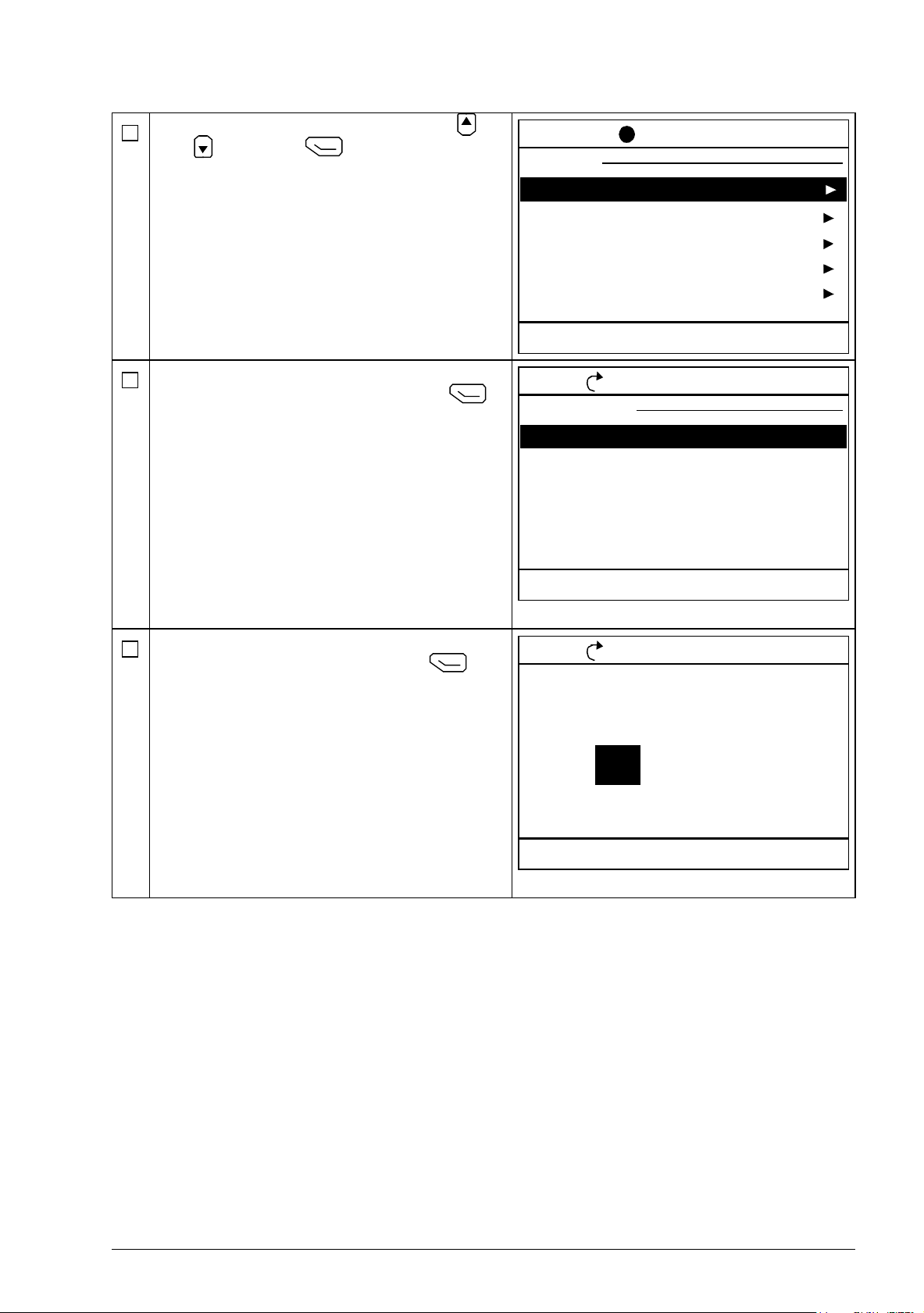
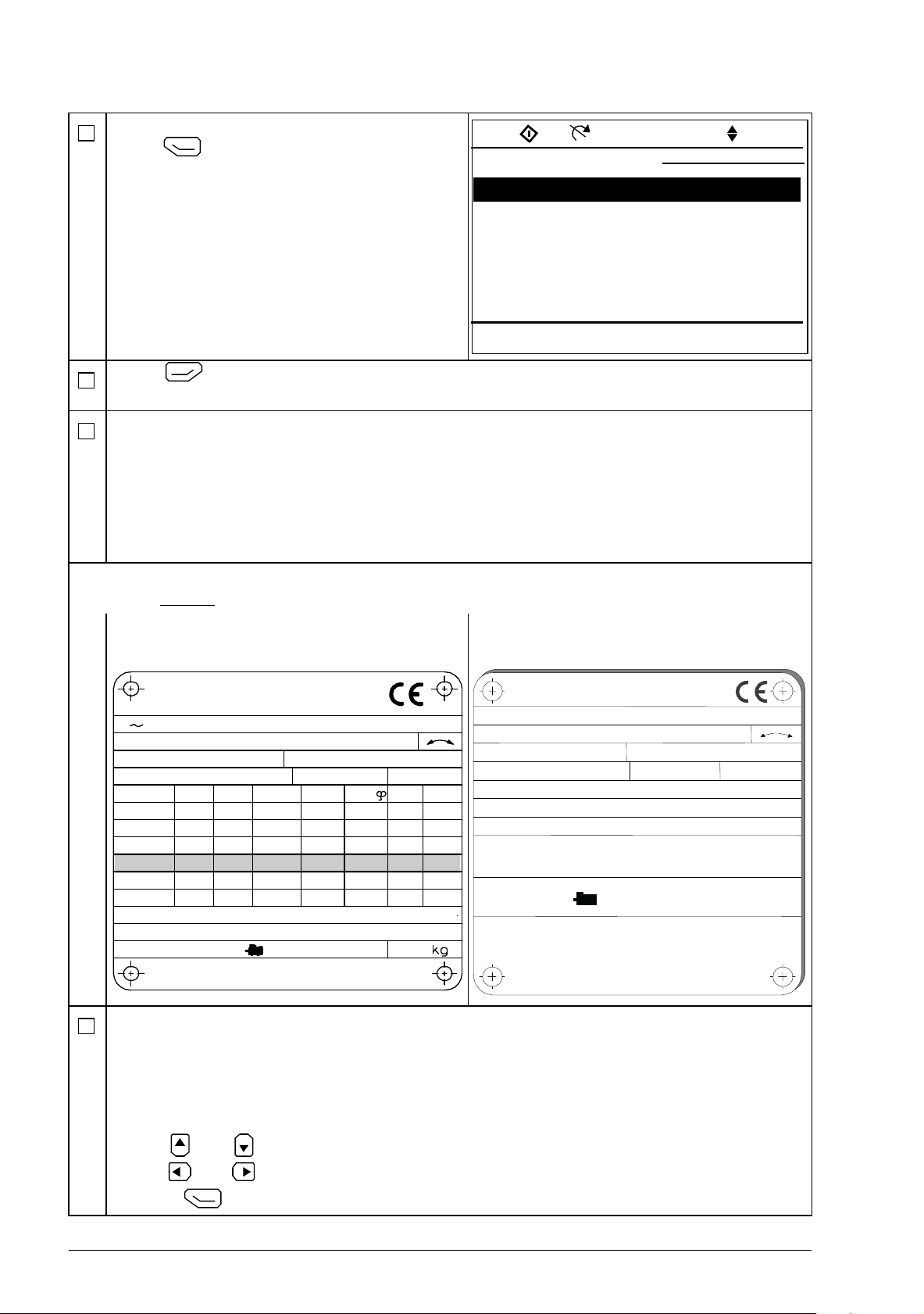
Highlight Settings on the menu using
Remote 0.0 rpm
Settings
Language
Date & time
Back
12:34
Select
Edit texts
Display settings
x
ACS880
Reset to defaults
Next daylight saving start 28.03.
Remote 0.0 rpm
Date & time
Date
Back
12:35
Edit
Time
Show date as
01.01.1980
12:34:56
day.month.year
Show time as 24-hour
Daylight saving EU
Remote 0.0 rpm
Date
Cancel
12:35
Save
Day Month Year
Tuesday
.01.198001
and and press (Select).
In the Settings menu, highlight Date & time
(if not already highlighted) and press
(Select).
Start-up 19
In the Date & time menu, highlight Date (if
not already highlighted) and press
(Select).
Page 20
20 Start-up
Remote 0.0 rpm
0.00
0.00
Motor torque
%
0.0
Motor current
A
Motor speed used
rpm
Options
12:34
Menu
ACS880
Loc/Rem
Local 0.0 rpm
0.00
0.00
Motor torque
%
0.0
Motor current
A
Motor speed used
rpm
Options
12:36
Menu
Local 0.0 rpm
Menu
Parameters
Assistants
Energy efficiency
Event log
Exit
12:36
Select
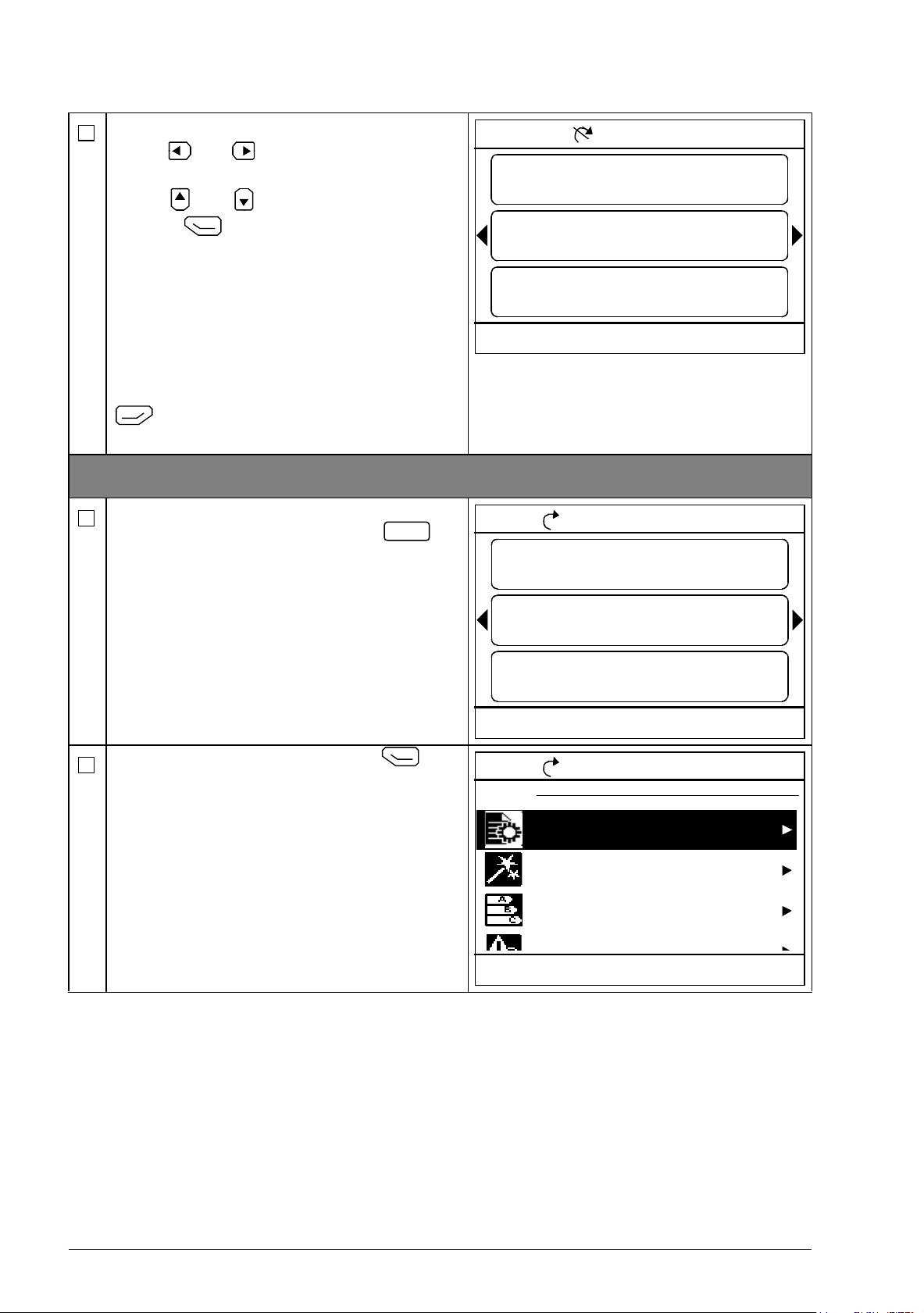
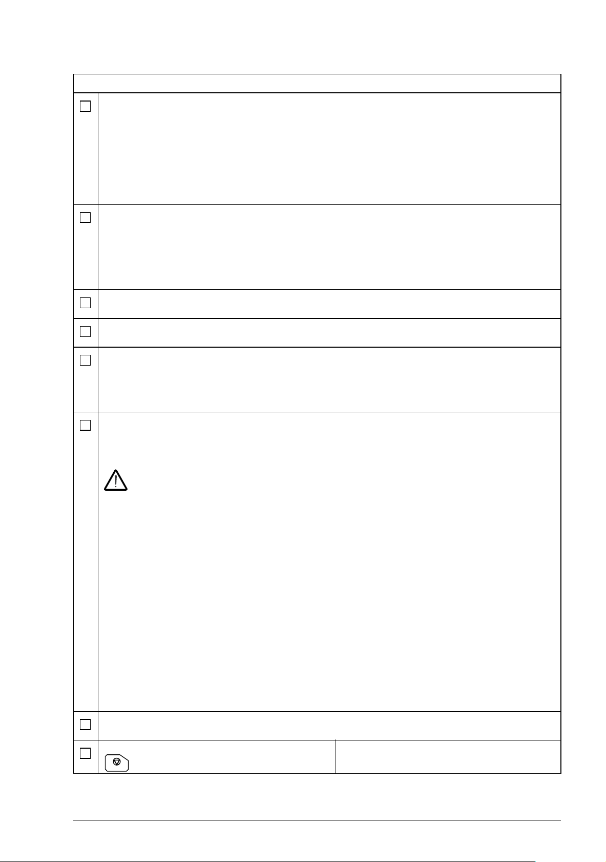
Set the correct date:
• Use and to move the cursor left
and right.
• Use and to change the value.
•Press (Save) to accept the new
setting.
Check/adjust all the remaining settings in the
Date & time menu.
The Show clock setting determines whether
the time is shown at all times in the bottom
pane of the display.
After you have made the settings, press
(Back or Exit) repeatedly until the
Home view (right) reappears.
2 – Supply voltage and motor data settings
Switch to local control to ensure that external
control is disabled by pressing the
key. Local control is indicated by the text
“Local” in the top pane.
Open the main Menu by pressing
(Menu).
Page 21
Highlight Parameters and press
Local 0.0 rpm
Parameters
Complete list
By function
Back
12:36
Select
Favorites
Modified
x
ACS880
Local 0.0 rpm
Complete list
01 Actual values
03 Input references
04 Warnings and faults
05 Diagnostics
06 Control and status words
07 System info
Back
12:36
Select
Local 0.0 rpm
95 HW configuration
95.01 Supply voltage
Back
12:36
Edit
95.08 DC switch monitoring
Not given
Internal 24 V
Disable
95.15 Special HW settings 0000
95.20 HW option wor... ...0 0000 0000
ACS880
95.04 Control board supply
Local 0.0 rpm
95.01 Supply voltage
[0] Not given
[1] 208…240 V
Cancel
12:36
Save
[2] 380…415 V
[3] 440…480 V
[4] 500 V
(Select).
Highlight Complete list using and
and press (Select).
A listing of parameter groups is displayed.
Start-up 21
Highlight parameter group 95 HW
configuration and press (Select).
Note that the list wraps around in either
direction between groups 99 and 01. In this
case, it is quicker to use to locate group
95 on the list.
After selecting a group, a listing of
parameters within the group is displayed.
Highlight parameter 95.01 Supply voltage (if
not already highlighted) and press
(Edit).
The available parameter settings are listed.
Page 22
22 Start-up
Local 0.0 rpm
95 HW configuration
95.01 Supply voltage
Back
12:36
Edit
95.08 DC switch monitoring
380...415 V
Internal 24 V
Disable
95.15 Special HW settings 0000
95.20 HW option wor... ...0 0000 0000
ACS880
95.04 Control board supply
M2AA 200 MLA 4
1475
1475
1470
1470
1475
1770
32.5
56
34
59
54
59
0.83
0.83
0.83
0.83
0.83
0.83
3GAA 202 001 - ADA
180
IEC 34-1
6210/C36312/C3
Cat. no
35
30
30
30
30
30
50
50
50
50
50
60
690 Y
400 D
660 Y
380 D
415 D
440 D
V
Hz kW
r/min A
cos
IA/IN
t
E/s
Ins.cl. F
IP 55
No
IEC 200 M/L 55
3
motor
ABB Motors
3 ~ motor M2BJ 280SMB 10 B3
No 3424522
A
BB Motors
Ins.cl. F IP 55
V
400 DHz50kW55
r/min
600
A
103
cos
M
0.97
IA/IN
t
E/s
Prod. code 2GBJ285220-ADA405445477
6316/C3
6316/C3
630kg
IEC 34-1
S1 SPEC INSUL.
JK-21640-1
Highlight the correct setting on the list and
press (Save).
Press (Back) to display the list of parameter groups again. Select parameter group
99 Motor data, and set parameter 99.03 Motor type.
Set parameter 99.04 Motor control mode.
DTC = Direct torque control; Scalar
DTC is suitable for most cases. Scalar mode is recommended if
• the nominal current of the motor is less than 1/6 of the nominal current of the drive,
• the drive is used for test purposes with no motor connected, or
• the drive controls multiple motors and the number of motors connected is variable.
Refer to the motor nameplate for the following parameter settings. Whenever possible, enter
the values exactly
as shown on the motor nameplate.
Example of a nameplate of an induction
(asynchronous) motor:
99.06 Motor nominal current
The allowable range is
• in DTC mode: 1/6 × I
• in Scalar mode: 0 … 2 × I
Note: With numerical parameter values:
• Use and to change the value of a digit.
• Use and to move the cursor left and right.
•Press (Save) to enter the value.
Hd
… 2 × IHd of the drive
Hd
Example of a nameplate of a permanent
magnet motor:
Page 23
Make the following parameter settings in the same manner.
99.07 Motor nominal voltage
Start-up 23
The allowable range is 1/6 × U
… 2 × UN of the drive.
N
With permanent magnet motors, the nominal voltage is the BackEMF voltage at nominal
speed. If the voltage is given in volt/rpm (eg. 60 V per 1000 rpm), the voltage at a nominal
speed of 3000 rpm is 3 × 60 V = 180 V. Note that nominal voltage is not the same as
equivalent DC motor voltage (EDCM) given by some manufacturers. The nominal voltage
can be calculated by dividing the EDCM voltage by 1.7 (or square root of 3).
99.08 Motor nominal frequency
With permanent magnet motors, if the nominal frequency is not shown on the nameplate,
it can be calculated using the following formula:
f = n × p / 60
where n = nominal motor speed, p = number of pole pairs.
99.09 Motor nominal speed
99.10 Motor nominal power
99.11 Motor nominal cos Φ
99.12 Motor nominal torque
These values are not required, but can be entered to improve control accuracy. If you do
not know the correct values, leave the parameters at 0. DO NOT enter estimated values.
99.13 ID run requested
This parameter selects the mode of the identification run (DTC motor control mode only).
Note: The drive must be in local control for the identification run.
WARNING! The identification run modes marked thus * will run the motor in the
forward direction (see below for details). Make sure it is safe to run the motor
before choosing any of these modes.
*Normal mode should be selected whenever possible.. The driven machinery must be de-
coupled from the motor if
• the load torque is higher than 20%, or
• the machinery is not able to withstand the nominal torque transient during the
identification run.
*Reduced mode should be selected if the mechanical losses are higher than 20%, ie. the
load cannot be de-coupled, or full flux is required to keep the motor brake open (eg. with
conical motors).
The Standstill mode should be selected if neither the *Normal or *Reduced mode can be
used. Notes:
• This mode cannot be used with a permanent magnet motor if the load torque is higher
than 20% of nominal.
• Mechanical brake is not opened by the logic for the identification run.
Ensure that the Safe torque off and emergency stop circuits (if present) are closed.
Start the identification run by pressing the
(Start) button.
A warning will indicate that the
identification run is in progress.
Page 24

24 Start-up
Check that the motor runs in the correct direction (forward direction shown below).
The identification run has completed when the drive stops and the value of parameter
99.13 reverts to None.
If the motor ran in the wrong direction, correct the motor cabling or adjust parameter
99.16 Motor phase order.
Page 25

Control locations and operating modes 25
4
Control locations and operating modes
What this chapter contains
This chapter describes the control locations and operating modes supported by the
control program.
Page 26
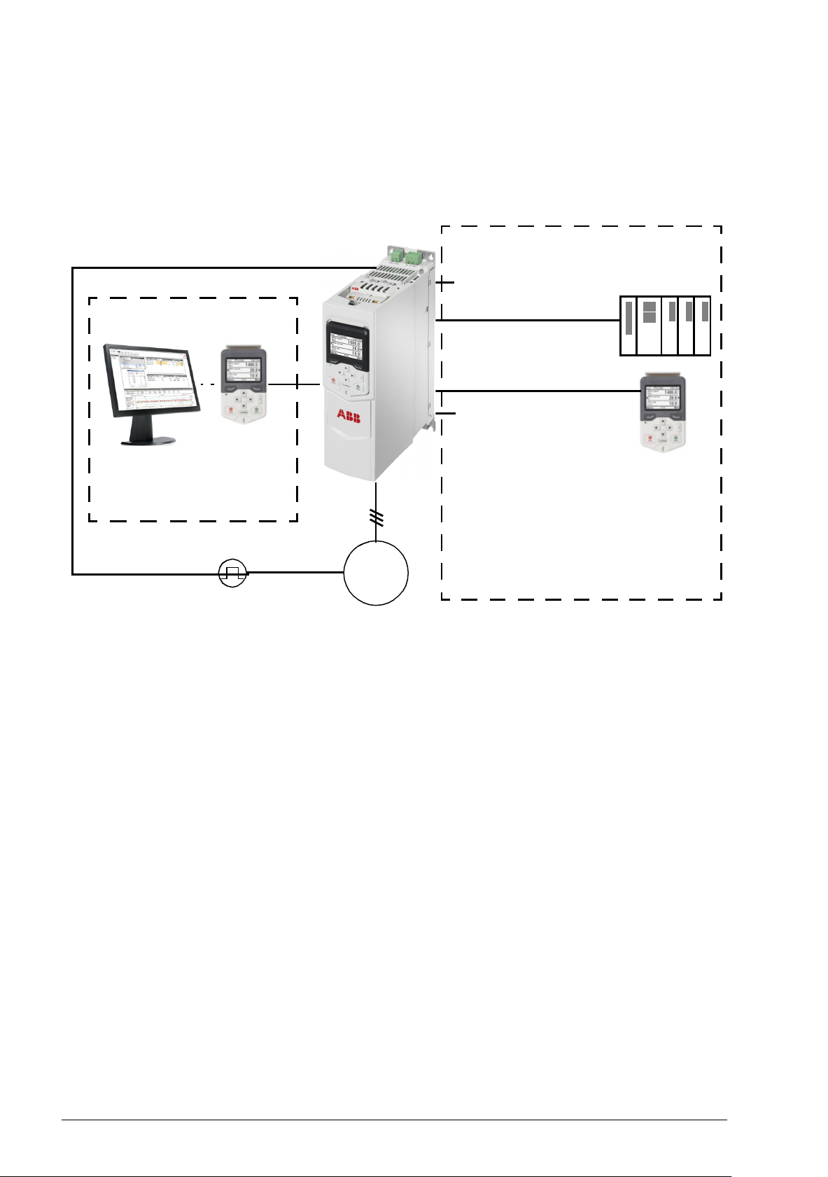
26 Control locations and operating modes
Control panel or Drive
composer PC tool (optional)
Fieldbus adapter (Fxxx)
1) Extra inputs/outputs can be added by installing optional I/O extension modules (FIO-xx) in
drive slots.
2) Encoder or resolver interface module(s) (FEN-xx) installed in drive slots.
MOTOR
PLC
M
3~
I/O
1)
Embedded fieldbus
interface (EFB) or
master/follower link
External control
Local control
Encoder
ACS880-M04
Control panel
2)
Local control vs. external control
The ACS880-M04 has two main control locations: external and local. The control
location is selected with the Loc/Rem key on the control panel or in the PC tool.
Local control
The control commands are given from the control panel keypad or from a PC
equipped with Drive composer when the drive is set to local control. Speed and
torque control modes are available for local control; frequency mode is available
when scalar motor control mode is used (see parameter 19.16 Local control mode).
Local control is mainly used during commissioning and maintenance. The control
panel always overrides the external control signal sources when used in local control.
Changing the control location to local can be prevented by parameter 19.17 Local
control disable.
The user can select by a parameter (49.05 Communication loss action) how the drive
reacts to a control panel or PC tool communication break. (The parameter has no
effect in external control.)
Page 27

Control locations and operating modes 27
External control
When the drive is in external control, control commands are given through
• the I/O terminals (digital and analog inputs), or optional I/O extension modules
• the embedded fieldbus interface or an optional fieldbus adapter module
• the master/follower link, and/or
• the control panel.
Two external control locations, EXT1 and EXT2, are available. The user can select
the sources of the start and stop commands separately for each location by
parameters 20.01…20.10. The operating mode can be selected separately for each
location (in parameter group 19 Operation mode), which enables quick switching
between different operating modes, for example speed and torque control. Selection
between EXT1 and EXT2 is done via any binary source such as a digital input or
fieldbus control word (see parameter 19.11 Ext1/Ext2 selection). The source of
reference is selectable for each operating mode separately.
Using the control panel as an external control source
The control panel can also be used as a source of start/stop commands and/or
reference in external control. Selections for the control panel are available in the
start/stop command source and reference source selection parameters.
Reference source selection parameters have two selections for the control panel. The
difference between the two selections is in the initial reference value after the
reference source switches to the control panel.
The panel reference is saved whenever another reference source is selected. If the
reference source selection parameter is set to Control panel (ref saved), the saved
value is used as the initial reference when control switches back to the panel. Note
that only one type of reference can be saved at a time: for example, attempting to use
the same saved reference with different operating modes (speed, torque, etc.)
causes the drive to trip on 7083 Panel reference conflict. The panel reference can be
separately limited by parameters in group 49 Panel port communication.
With the reference source selection parameter set to Control panel (ref copied), the
initial panel reference value depends on whether the operating mode changes with
the reference source. If the source switches to the panel and the operating mode
does not change, the last reference from the previous source is adopted. If the
operating mode changes, the drive actual value corresponding to the new mode is
adopted as the initial value.
Page 28
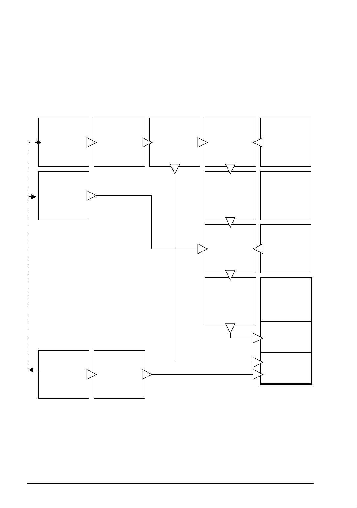
28 Control locations and operating modes
Motor feedback
configuration
(p 569)
Speed
reference
source selection
I
(p 566)
Speed controller
(p 572)
Speed reference
source selection
II
(p 567)
Speed reference
ramping and
shaping
(p 568)
Speed error
calculation
(p 571)
Torque
reference
source selection
and modification
(p 573)
Reference
selection for
torque controller
(p 575)
Frequency
reference
source selection
and modification
(p 578)
Operating mode
selection
(p 574)
Torque
controller
(p 577)
DTC motor
control mode
Scalar motor
control mode
Torque limitation
(p 576)
Frequency
reference
modification
(p 579)
Load feedback
and position
counter
configuration
(p 570)
Operating modes of the drive
The drive can operate in several operating modes with different types of reference.
The mode is selectable for each control location (Local, EXT1 and EXT2) in
parameter group 19 Operation mode.
The following is a general representation of the reference types and control chains.
The page numbers refer to detailed diagrams in chapter Control chain diagrams.
Page 29

Control locations and operating modes 29
Speed control mode
The motor follows a speed reference given to the drive. This mode can be used either
with estimated speed as feedback, or with an encoder or resolver for better speed
control accuracy.
Speed control mode is available in both local and external control. It is also available
both in DTC (Direct Torque Control) and scalar motor control modes.
Torque control mode
Motor torque follows a torque reference given to the drive. Torque control is possible
without feedback, but is much more dynamic and accurate when used in conjunction
with a feedback device such as an encoder or a resolver. It is recommended that a
feedback device is used in crane, winch or lift control situations.
Torque control mode is available in DTC motor control mode for both local and
external control locations.
Frequency control mode
The motor follows a frequency reference given to the drive. Frequency control is only
available in scalar motor control mode.
Special control modes
In addition to the control modes mentioned above, the following special control
modes are available:
• Emergency stop modes Off1 and Off3: Drive stops along the defined deceleration
ramp and drive modulation stops.
• Jogging mode: Drive starts and accelerates to the defined speed when the
jogging signal is activated. For more information, see section Jogging (page 57).
Page 30

30 Control locations and operating modes
Page 31

5
Program features
Program features 31
What this chapter contains
The control program contains all of the parameters (including actual signals) within
the drive. This chapter describes some of the more important functions within the
control program, how to use them and how to program them to operate.
Page 32

32 Program features
Application program
Firmware
Speed control
Torque control
Frequency control
Drive logic
I/O interface
Fieldbus interface
Protections
Feedback
Standard
block library
Function block
program
Drive control program
Parameter
interface
M
Drive configuration and programming
The drive control program is divided into two parts:
• firmware program
• application program.
The firmware program performs the main control functions, including speed and
torque control, drive logic (start/stop), I/O, feedback, communication and protection
functions. Firmware functions are configured and programmed with parameters, and
can be extended by application programming.
Programming via parameters
Parameters configure all of the standard drive operations and can be set via
• the control panel, as described in chapter Using the control panel
• the Drive composer PC tool, as described in Drive composer user’s manual
(3AUA0000094606 [English]), or
• the fieldbus interface, as described in chapters Fieldbus control through the
embedded fieldbus interface (EFB) and Fieldbus control through a fieldbus
adapter.
All parameter settings are stored automatically to the permanent memory of the drive.
However, if an external +24 V DC power supply is used for the drive control unit, it is
highly recommended to force a save by using parameter 96.07 Parameter save
manually before powering down the control unit after any parameter changes have
been made.
If necessary, the default parameter values can be restored by parameter 96.06
Parameter restore.
Page 33

Program features 33
Adaptive programming
Conventionally, the user can control the operation of the drive by parameters.
However, the standard parameters have a fixed set of choices or a setting range. To
further customize the operation of the drive, an adaptive program can be constructed
out of a set of function blocks.
The Drive composer pro PC tool (version 1.9 or later, available separately) has an
Adaptive programming feature with a graphical user interface for building the custom
program. The function blocks include the usual arithmetic and logical functions, as
well as eg. selection, comparison and timer blocks. The program can contain
approximately 20 blocks depending on block size and the number of inputs and
outputs used.
The physical inputs, drive status information, actual values, constants and data
storage parameters can be used as the input for the program. The output of the
program can be used eg. as a start signal, external event or reference, or connected
to the drive outputs. See below for a listing of the available inputs and outputs. Note
that connecting the output of the adaptive program to a selection parameter will writeprotect the parameter.
The status of the adaptive program is shown by parameter 07.30 Adaptive program
status.
For more information, see the Adaptive programming application guide
(3AXD50000028574 [English]).
Inputs available to the adaptive program
Input Source
I/O
DI1 10.02 DI delayed status, bit 0
DI2 10.02 DI delayed status, bit 1
DI3 10.02 DI delayed status, bit 2
DI4 10.02 DI delayed status, bit 3
DI5 10.02 DI delayed status, bit 4
DI6 10.02 DI delayed status, bit 5
DIIL 10.02 DI delayed status, bit 15
AI1 12.11 AI1 actual value
AI2 12.21 AI2 actual value
DIO1 11. 0 2 DIO delayed status, bit 0
DIO2 11. 0 2 DIO delayed status, bit 1
Actual signals
Motor speed 01.01 Motor speed used
Output frequency 01.06 Output frequency
Motor current 01.07 Motor current
Motor torque 01.10 Motor torque
Motor shaft power 01.17 Motor shaft power
Status
Enabled 06.16 Drive status word 1, bit 0
Inhibited 06.16 Drive status word 1, bit 1
Ready to start 06.16 Drive status word 1, bit 3
Page 34

34 Program features
Inputs available to the adaptive program
Input Source
Tripped 06.11 Main status word, bit 3
At setpoint 06.11 Main status word, bit 8
Limiting 06.16 Drive status word 1, bit 7
Ext1 active 06.16 Drive status word 1, bit 10
Ext2 active 06.16 Drive status word 1, bit 11
Data storage
Data storage 1 real32 47.01 Data storage 1 real32
Data storage 2 real32 47.02 Data storage 2 real32
Data storage 3 real32 47.03 Data storage 3 real32
Data storage 4 real32 47.04 Data storage 4 real32
Data storage 5 real32 47.05 Data storage 5 real32
Data storage 6 real32 47.06 Data storage 6 real32
Data storage 7 real32 47.07 Data storage 7 real32
Data storage 8 real32 47.08 Data storage 8 real32
Outputs available to the adaptive program
Output Target
I/O
RO1 10.24 RO1 source
RO2 10.27 RO2 source
RO3 10.30 RO3 source
AO1 13.12 AO1 source
AO2 13.22 AO2 source
DIO1 11.06 DIO1 output source
DIO2 11.10 DIO2 output source
Start control
Ext1/Ext2 selection 19.11 Ext1/Ext2 selection
Run enable 1 20.12 Run enable 1 source
Ext1 in1 cmd 20.03 Ext1 in1 source
Ext1 in2 cmd
Ext1 in3 cmd 20.05 Ext1 in3 source
Ext2 in1 cmd 20.08 Ext2 in1 source
Ext2 in2 cmd 20.09 Ext2 in2 source
Ext2 in3 cmd 20.10 Ext2 in3 source
Fault reset 31.11 Fault reset selection
Speed control
Ext1 speed reference 22.11 Speed ref1 source
Ext2 speed reference 22.12 Speed ref2 source
Speed additive 1 22.15 Speed additive 1 source
Frequency control
Ext1 frequency reference 28.11 Frequency ref1 source
Ext2 frequency reference 28.12 Frequency ref2 source
Torque control
Ext1 torque reference 26.11 Torque ref1 source
Ext2 torque reference 26.12 Torque ref2 source
Torque additive 2 26.25 Torque additive 2 source
Limit function
Minimum torque 2 30.21 Minimum torque 2 source
Maximum torque 2 30.22 Maximum torque 2 source
20.04 Ext1 in2 source
Page 35

Program features 35
Outputs available to the adaptive program
Output Target
Events
External event 1 31.01 External event 1 source
External event 2 31.03 External event 2 source
External event 3 31.05 External event 3 source
External event 4 31.07 External event 4 source
External event 5 31.09 External event 5 source
Application programming
The functions of the firmware program can be extended with application
programming. Application programmability is optionally available for the ACS880M04 primary control program.
Application programs can be built out of function blocks based on the IEC 61131-3
standard using a PC tool available separately.
For more information, see Programming manual: Drive application programming
(IEC 61131-3) (3AUA0000127808 [English]).
Page 36

36 Program features
Control interfaces
Programmable analog inputs
The control unit has two programmable analog inputs. Each of the inputs can be
independently set as a voltage (0/2…10 V or -10…10 V) or current (0/4…20 mA)
input by a jumper or switch on the control unit. Each input can be filtered, inverted
and scaled. The number of analog inputs can be increased by installing FIO-11 I/O
extensions (see Programmable I/O extensions below).
The drive can be set to perform an action (for example, to generate a warning or fault)
if the value of an analog input moves out of a predefined range.
Settings
Parameter group 12 Standard AI (page 136).
Programmable analog outputs
The control unit has two current (0…20 mA) analog outputs. Each output can be
filtered, inverted and scaled. The number of analog outputs can be increased by
installing FIO-11 I/O extensions (see Programmable I/O extensions below).
Settings
Parameter group 13 Standard AO (page 141).
Programmable digital inputs and outputs
The control unit has six digital inputs, a digital start interlock input, and two digital
input/outputs (I/O that can be set as either an input or an output).
One digital input (DI6) doubles as a PTC thermistor input. See section Motor thermal
protection (page 73).
Digital input/output DIO1 can be used as a frequency input, DIO2 as a frequency
output.
The number of digital inputs/outputs can be increased by installing FIO-01 or FIO-11
I/O extensions (see Programmable I/O extensions below).
Settings
Parameter groups 10 Standard DI, RO (page 122) and 11 Standard DIO, FI, FO
(page 130).
Page 37

Program features 37
Programmable relay outputs
The control unit has three relay outputs. The signal to be indicated by the outputs can
be selected by parameters.
Relay outputs can be added by installing FIO-01 I/O extensions.
Settings
Parameter group 10 Standard DI, RO (page 122).
Programmable I/O extensions
Inputs and outputs can be added by using I/O extension modules. One or two
modules can be mounted on the slots of the control unit.
The table below shows the number of I/O on the control unit as well as optional I/O
extension modules.
Digital
Location
Control unit 6 + DIIL2223
FIO-01 - 4 - - 2
FIO-11 -231 -
inputs
(DI)
Digital I/Os
(DIO)
Analog
inputs
(AI)
Analog
outputs
(AO)
Relay
outputs
(RO)
Two I/O extension modules can be activated and configured using parameter groups
14…15.
Note: Each configuration parameter group contains parameters that display the
values of the inputs on that particular extension module. These parameters are the
only way of utilizing the inputs on I/O extension modules as signal sources. To
connect to an input, choose the setting Other in the source selector parameter, then
specify the appropriate value parameter (and bit, for digital signals) in group 14 and
15.
Settings
Parameter groups 14 I/O extension module 1 (page 147) and 15 I/O extension
module 2 (page 169).
Page 38

38 Program features
Fieldbus control
The drive can be connected to several different automation systems through its
fieldbus interfaces. See chapters Fieldbus control through the embedded fieldbus
interface (EFB) (page 527) and Fieldbus control through a fieldbus adapter (page
551).
Settings
Parameter groups 50 Fieldbus adapter (FBA) (page 330), 51 FBA A settings (page
341), 52 FBA A data in (page 342), and 53 FBA A data out (page 343), 54 FBA B
settings (page 344), 55 FBA B data in (page 345), 56 FBA B data out (page 346), and
58 Embedded fieldbus (page 346).
Page 39

Program features 39
(For example)
Control word
Speed reference
Torque reference
(For example)
Status word
01.01 Motor speed used
01.10 Motor torque
Master
M
~
M
~
Master/follower link
DDCS
Follower
DDCS
Fieldbus control
External control system (eg. PLC)
Process master
Process follower
Speed-controlled
master
Torque- or speedcontrolled follower
Master/follower functionality
General
The master/follower functionality can be used to link several drives together so that
the load can be evenly distributed between the drives. This is ideal in applications
where the motors are coupled to each other via gearing, chain, belt, etc.
The external control signals are typically connected to one drive only which acts as
the master. The master controls up to 10 followers by sending broadcast messages
over an electrical cable or fiber optic link. The master can read feedback signals from
up to 3 selected followers.
Page 40

40 Program features
The master drive is typically speed-controlled and the other drives follow its torque or
speed reference. In general, a follower should be
• torque-controlled when the motor shafts of the master and the follower are rigidly
coupled by gearing, chain etc. so that no speed difference between the drives is
possible
• speed-controlled when the motor shafts of the master and the follower are flexibly
coupled so that a slight speed difference is possible. When both the master and
the follower are speed-controlled, drooping is also typically used (see parameter
25.08 Drooping rate). The distribution of load between the master and follower
can alternatively be adjusted as described under Load share function with a
speed-controlled follower below.
Note: With a speed-controlled follower (without load sharing), pay attention to the
acceleration and deceleration ramp times of the follower. If the ramp times are set
longer than in the master, the follower will follow its own acceleration/deceleration
ramp times rather than those from the master. In general, it is recommended to set
identical ramp times in both the master and the follower(s). Any ramp shape settings
(see parameters 23.16…23.19) should only be applied in the master.
In some applications, both speed control and torque control of the follower are
required. In those cases, the operating mode can be switched by parameter (19.12
Ext1 control mode or 19.14 Ext2 control mode). Another method is to set one external
control location to speed control mode, the other to torque control mode. Then, a
digital input of the follower can be used to switch between the control locations. See
chapter Control locations and operating modes (page 25).
With torque control, follower parameter 26.15 Load share can be used to scale the
incoming torque reference for optimal load sharing between the master and the
follower. Some torque-controlled follower applications, eg. where the torque is very
low, or very low speed operation is required, may require encoder feedback.
If a drive needs to quickly switch between master and follower statuses, one user
parameter set (see page 82) can be saved with the master settings, another with the
follower settings. The suitable settings can then be activated using eg. digital inputs.
Load share function with a speed-controlled follower
Load sharing between the master and a speed-controlled follower can be used in
various applications. The load share function is implemented by fine-tuning the
follower speed reference with an additional term based on a torque reference. The
torque reference is selected by parameter 23.42 Follower speed corr torq source (by
default, reference 2 received from the master). Load share is adjusted by parameter
26.15 Load share and activated by the source selected by 23.40 Follower speed
correction enable. Parameter 23.41 Follower speed correction gain provides a gain
adjustment for the speed correction. The final correction term added to the speed
reference is shown by 23.39 Follower speed correction out. See the block diagram on
page 571.
Page 41

Program features 41
Notes:
• The function can be enabled only when the drive is a speed-controlled follower in
remote control mode.
• Drooping (25.08 Drooping rate) is ignored when the load share function is active.
• The master and follower should have the same speed control tuning values.
• The speed correction term is limited by the speed error window parameters 24.44
Speed error window low and 24.43 Speed error window high. An active limitation
is indicated by 06.19 Speed control status word.
Communication
A master/follower link can be built by connecting the drives together with fiber optic
cables (may require additional equipment depending on existing drive hardware), or
by wiring together the XD2D connectors of the drives. The medium is selected by
parameter 60.01 M/F communication port.
Parameter 60.03 M/F mode defines whether the drive is the master or a follower on
the communication link. Typically, the speed-controlled process master drive is also
configured as the master in the communication.
The communication on the master/follower link is based on the DDCS protocol, which
employs data sets (specifically, data set 41). One data set contains three 16-bit
words. The contents of the data set are freely configurable using parameters
61.01…61.03. The data set broadcast by the master typically contains the control
word, speed reference and torque reference, while the followers return a status word
with two actual values.
The default setting of parameter 61.01 M/F data 1 selection is Follower CW. With this
setting in the master, a word consisting of bits 0…11 of 06.01 Main control word and
four bits selected by parameters 06.45…06.48 is broadcast to the followers.
However, bit 3 of the follower control word is modified so that it remains on as long as
the master is modulating, and its switching to 0 causes the follower to coast to a stop.
This is to synchronize the stopping of both master and follower.
Note: When the master is ramping down to a stop, the follower observes the
decreasing reference but receives no stop command until the master stops
modulating and clears bit 3 of the follower control word. Because of this, the
maximum and minimum speed limits on the follower drive should not have the same
sign – otherwise the follower would be pushing against the limit until the master finally
stops.
Three words of additional data can optionally be read from each follower. The
followers from which data is read are selected by parameter 60.14 M/F follower
selection in the master. In each follower drive, the data to be sent is selected by
parameters 61.01…61.03. The data is transferred in integer format over the link, and
displayed by parameters 62.28…62.36 in the master. The data can then be
forwarded to other parameters using 62.04…62.12.
Page 42

42 Program features
Master/follower wiring with electrical cable
Master
Termination ON
1
2
3
4
1
2
3
4
1
2
3
4
XD2D
B
XD2D
XD2D
A
BGND
Shield
B
A
BGND
Shield
B
A
BGND
Shield
Follower 1
Termination OFF
Follower n
Termination ON
See the hardware manual of the drive for wiring and termination details.
To indicate faults in the followers, each follower must be configured to transmit its
status word as one of the above-mentioned data words. In the master, the
corresponding target parameter must be set to Follower SW. The action to be taken
when a follower is faulted is selected by 60.17 Follower fault action. External events
(see parameter group 31 Fault functions) can be used to indicate the status of other
bits of the status word.
Block diagrams of the master/follower communication are presented on pages 580
and 581.
Construction of the master/follower link
The master/follower link is formed by connecting the drives together using shielded
twisted-pair cable between the XD2D terminals of the drives.
Example parameter settings
The following is a checklist of parameters that need to be set when configuring the
master/follower link. In this example, the master broadcasts the Follower control
word, a speed reference and a torque reference. The follower returns a status word
and two actual values (this is not compulsory but is shown for clarity).
Master settings
• Master/follower link activation
:
• 60.01 M/F communication port (XD2D selection)
•(60.02 M/F node address = 1)
• 60.03 M/F mode = D2D master
Page 43

Program features 43
• 60.05 M/F HW connection (Ring for fiber optic)
• Data to be broadcast to the followers
• 61.01 M/F data 1 selection = Follower CW (Follower control word)
• 61.02 M/F data 2 selection = Used speed reference
• 61.03 M/F data 3 selection = Torque reference act 5
• Data to be read from the followers (optional)
• 60.14 M/F follower selection (selection of followers that data is read from)
• 62.04 Follower node 2 data 1 sel … 62.12 Follower node 4 data 3 sel
(mapping of data received from followers)
Follower settings
• Master/follower link activation
• 60.01 M/F communication port (XD2D selection)
• 60.02 M/F node address = 2…60
• 60.03 M/F mode = D2D follower
• 60.05 M/F HW connection
• Mapping of data received from master
• 62.01 M/F data 1 selection = CW 16bit
• 62.02 M/F data 2 selection = Ref1 16bit
• 62.03 M/F data 3 selection = Ref2 16bit
• Selection of operating mode and control location
• 19.12 Ext1 control mode = Speed or Torq ue
• 20.01 Ext1 commands = M/F link
• 20.02 Ext1 start trigger type = Level
• Selection of reference sources
• 22.11 Speed ref1 source = M/F reference 1
• 26.11 Torque ref1 source = M/F reference 2
• Selection of data to be sent to master (optional)
• 61.01 M/F data 1 selection = SW 16bit
• 61.02 M/F data 2 selection = Act1 16bit
• 61.03 M/F data 3 selection = Act2 16bit
:
Settings and diagnostics
Parameter groups 60 DDCS communication (page 357), 61 D2D and DDCS transmit
data (page 366) and 62 D2D and DDCS receive data (page 370).
Page 44

44 Program features
3 3 . 1
3 2 . 1
3 2 . 2
3 3 . 3
3 2 . 3
3 3 . 2
1 9 . 0 1
1 2 3 4
1
2 4 . 0 3 4 3 0 0
.
.
.
.
.
.
.
.
.
.
.
.
Data set
Data set
Data set
Data set
Data set
Data set
Par.
Value
Parameter write to drive
Parameter read from drive
Transmit address
Value = 4865*
Transmit data
Value = 1234
Transmit address
feedback
Value = 4865*
Inquire address
Value = 6147**
Inquired data
Value = 4300
Inquire address
feedback
Value = 6147**
MASTER
FOLLOWER
*19.01 -> 13h.01h -> 1301h = 4865
**24.03 -> 18h.03h -> 1803h = 6147
External controller interface
Communication
The communication between the master and the follower consists of data sets of
three 16-bit words each. The master sends a data set to the follower, which returns
the next data set to the master.
The communication uses data sets 10…33. The contents of the data sets are freely
configurable, but data set 10 typically contains the control word and one or two
references, while data set 11 returns the status word and selected actual values.
The word that is defined as the control word is internally connected to the drive logic;
the coding of the bits is as presented in section Contents of the fieldbus Control word
(page 558). Likewise, the coding of the status word is as shown in section Contents of
the fieldbus Status word (page 559).
By default, data sets 32 and 33 are dedicated for the mailbox service, which enables
the setting or inquiry of parameter values as follows:
The update intervals of the data sets are as follows:
• Data sets 10…11: 2 ms
• Data sets 12…13: 4 ms
• Data sets 14…17: 10 ms
• Data sets 18…25, 32, 33: 100 ms.
Settings
Parameter groups 60 DDCS communication (page 357), 61 D2D and DDCS transmit
data (page 366) and 62 D2D and DDCS receive data (page 370).
Page 45

Program features 45
Motor control
Direct torque control (DTC)
The motor control of the ACS880-M04 is based on direct torque control (DTC), the
ABB premium motor control platform. The switching of the output semiconductors is
controlled to achieve the required stator flux and motor torque. The switching
frequency is changed only if the actual torque and stator flux values differ from their
reference values by more than the allowed hysteresis. The reference value for the
torque controller comes from the speed controller or directly from an external torque
reference source.
Motor control requires measurement of the DC voltage and two motor phase
currents. Stator flux is calculated by integrating the motor voltage in vector space.
Motor torque is calculated as a cross product of the stator flux and the rotor current.
By utilizing the identified motor model, the stator flux estimate is improved. Actual
motor shaft speed is not needed for the motor control.
The main difference between traditional control and DTC is that torque control
operates at the same time level as the power switch control. There is no separate
voltage and frequency controlled PWM modulator; the output stage switching is
wholly based on the electromagnetic state of the motor.
The best motor control accuracy is achieved by activating a separate motor
identification run (ID run).
See also section Scalar motor control (page 59).
Settings
Parameters 99.04 Motor control mode (page 426) and 99.13 ID run requested (page
429).
Reference ramping
Acceleration and deceleration ramping times can be set individually for speed, torque
and frequency reference.
With a speed or frequency reference, the ramps are defined as the time it takes for
the drive to accelerate or decelerate between zero speed or frequency and the value
defined by parameter 46.01 Speed scaling or 46.02 Frequency scaling. The user can
switch between two preset ramp sets using a binary source such as a digital input.
For speed reference, also the shape of the ramp can be controlled.
With a torque reference, the ramps are defined as the time it takes for the reference
to change between zero and nominal motor torque (parameter 01.30 Nominal torque
scale).
Page 46

46 Program features
Special acceleration/deceleration ramps
The acceleration/deceleration times for the jogging function can be defined
separately; see section Jogging (page 57).
The change rate of the motor potentiometer function (page 67) is adjustable. The
same rate applies in both directions.
A deceleration ramp can be defined for emergency stop (“Off3” mode).
Settings
• Speed reference ramping: Parameters 23.11…23.19 and 46.01
(pages 209 and 320).
• Torque reference ramping: Parameters 01.30, 26.18 and 26.19
(pages 96 and 237).
• Frequency reference ramping: Parameters 28.71…28.75 and 46.02
(pages 250 and 320).
• Jogging: Parameters 23.20 and 23.21 (page 212).
• Motor potentiometer: Parameter 22.75 (page 207).
• Emergency stop (“Off3” mode): Parameter 23.23 Emergency stop time
(page 213).
Constant speeds/frequencies
Constant speeds and frequencies are predefined references that can be quickly
activated, for example, through digital inputs. It is possible to define up to 7 constant
speeds for speed control and 7 constant frequencies for frequency control.
WARNING: Constant speeds and frequencies override the normal reference
irrespective of where the reference is coming from.
Settings
Parameter groups 22 Speed reference selection (page 198) and 28 Frequency
reference chain (page 243).
Critical speeds/frequencies
Critical speeds (sometimes called “skip speeds”) can be predefined for applications
where it is necessary to avoid certain motor speeds or speed ranges because of, for
example, mechanical resonance problems.
The critical speeds function prevents the reference from dwelling within a critical band
for extended times. When a changing reference (22.87 Speed reference act 7) enters
a critical range, the output of the function (22.01 Speed ref unlimited) freezes until the
reference exits the range. Any instant change in the output is smoothed out by the
ramping function further in the reference chain.
Page 47

Program features 47
540
690
1380
1560
1Par. 22.52 = 540 rpm
2Par. 22.53 = 690 rpm
3Par. 22.54 = 1380 rpm
4Par. 22.55 = 1560 rpm
1234
22.01 Speed ref unlimited (rpm)
(output of function)
22.87 Speed reference act 7 (rpm)
(input of function)
The function is also available for scalar motor control with a frequency reference. The
input of the function is shown by 28.96 Frequency ref act 7, the output by 28.97
Frequency ref unlimited.
Example
A fan has vibrations in the range of 540 to 690 rpm and 1380 to 1560 rpm. To make
the drive avoid these speed ranges,
• enable the critical speeds function by turning on bit 0 of parameter 22.51 Critical
speed function, and
• set the critical speed ranges as in the figure below.
Settings
• Critical speeds: parameters 22.51…22.57 (page 204)
• Critical frequencies: parameters 28.51…28.57 (page 249).
Speed controller autotune
The speed controller of the drive can be automatically adjusted using the autotune
function. Autotuning is based on an estimation of the mechanical time constant
(inertia) of the motor and machine.
The autotune routine will run the motor through a series of acceleration/deceleration
cycles, the number of which can be adjusted by parameter 25.40 Autotune repeat
times. Higher values will produce more accurate results, especially if the difference
between initial and maximum speeds is small.
The maximum torque reference used during autotuning will be the initial torque (ie.
torque when the routine is activated) plus 25.38 Autotune torque step, unless limited
by the maximum torque limit (parameter group 30 Limits) or the nominal motor torque
(99 Motor data). The calculated maximum speed during the routine is the initial speed
(ie. speed when the routine is activated) + 25.39 Autotune speed step, unless limited
by 30.12 Maximum speed or 99.09 Motor nominal speed.
Page 48

48 Program features
Initial torque + [25.38]
t
Initial torque
Initial speed + [25.39]
Initial speed
The diagram below shows the behavior of speed and torque during the autotune
routine. In this example, 25.40 Autotune repeat times is set to 2.
Notes:
• If the drive cannot produce the requested braking power during the routine, the
results will be based on the acceleration stages only, and not as accurate as with
full braking power.
• The motor will exceed the calculated maximum speed slightly at the end of each
acceleration stage.
Before activating the autotune routine
The prerequisites for performing the autotune routine are:
• The motor identification run (ID run) has been successfully completed
• Speed and torque limits (parameter group 30 Limits) have been set
• The speed feedback has been monitored for noise, vibrations and other
disturbances caused by the mechanics of the system, and
• speed feedback filtering (parameter group 90 Feedback selection)
• speed error filtering (24 Speed reference conditioning) and
• zero speed (parameters 21.06 and 21.07)
have been set to eliminate these disturbances.
• The drive has been started and is running in speed control mode.
After these conditions have been fulfilled, autotuning can be activated by parameter
25.33 Speed controller autotune (or the signal source selected by it).
Page 49

Program features 49
A: Undercompensated
B: Normally tuned (autotuning)
C: Normally tuned (manually). Better dynamic performance than with B
D: Overcompensated speed controller
%
t
n
C
B
D
n
N
A
Autotune modes
Autotuning can be performed in three different ways depending on the setting of
parameter 25.34 Speed controller autotune mode. The selections Smooth, Normal
and Tight define how the drive torque reference should react to a speed reference
step after tuning. The selection Smooth will produce a slow but robust response;
Tight will produce a fast response but possibly too high gain values for some
applications. The figure below shows speed responses at a speed reference step
(typically 1…20%).
Autotune results
At the end of a successful autotune routine, its results are automatically transferred
into parameters
• 25.02 Speed proportional gain (proportional gain of the speed controller)
• 25.03 Speed integration time (integration time of the speed controller)
• 25.37 Mechanical time constant (mechanical time constant of the motor and
machine).
Nevertheless, it is still possible to manually adjust the controller gain, integration time
and derivation time.
Page 50

50 Program features
Derivative
Proportional,
integral
Derivative
acceleration
compensation
Torque
reference
Speed
reference
Actual speed
Error
value
-
+
+
+
+
The figure below is a simplified block diagram of the speed controller. The controller
output is the reference for the torque controller.
Warning indications
A warning message, AF90 Speed controller autotuning, will be generated if the
autotune routine does not complete successfully. See chapter Fault tracing (page
479) for further information.
Settings
Parameters 25.33…25.40 (page 232).
Oscillation damping
The oscillation damping function can be used to cancel out oscillations caused by
mechanics or an oscillating DC voltage. The input – a signal reflecting the oscillation
– is selected by parameter 26.53 Oscillation compensation input. The oscillation
damping function outputs a sine wave (26.58 Oscillation damping output) which can
be summed with the torque reference with a suitable gain (26.57 Oscillation damping
gain) and phase shift (26.56 Oscillation damping phase).
The oscillation damping algorithm can be activated without connecting the output to
the reference chain, which makes it possible to compare the input and output of the
function and make further adjustments before applying the result.
Page 51

Tuning procedure for oscillation damping
• Select the input by 26.53 Oscillation compensation input
• Activate algorithm by 26.51 Oscillation damping
•Set 26.57 Oscillation damping gain to 0
• Calculate the oscillation frequency from the signal (use the Drive
composer PC tool) and set 26.55 Oscillation damping frequency
•Set 26.56 Oscillation damping phase*
• Increase 26.57 Oscillation damping gain gradually so that the
algorithm starts to take effect.
oscillation amplitude decreases oscillation amplitude increases
• Increase 26.57 Oscillation damping gain
and adjust 26.56 Oscillation damping
phase if necessary
• Try other values for 26.56 Oscillation
damping phase
• Increase 26.57 Oscillation damping gain to
suppress the oscillation totally.
*If the phasing of a DC oscillation cannot be
determined by measuring, the value of 0
degrees is usually a suitable initial value.
Program features 51
Note: Changing the speed error low-pass filter time constant or the integration time of
the speed controller can affect the tuning of the oscillation damping algorithm. It is
recommended to tune the speed controller before the oscillation damping algorithm.
(The speed controller gain can be adjusted after the tuning of this algorithm.)
Settings
Parameters 26.51…26.58 (page 239).
Rush control
In torque control, the motor could potentially rush if the load were suddenly lost. The
control program has a rush control function that decreases the torque reference
whenever the motor speed exceeds 30.11 Minimum speed or 30.12 Maximum speed.
Page 52

52 Program features
Motor speed
Time
Overspeed trip level
Overspeed trip level
31.30 Overspeed trip margin
0
31.30 Overspeed trip margin
30.12
30.11
Rush control active
The function is based on a PI controller. The proportional gain and integration time
can be defined by parameters. Setting these to zero disables rush control.
Settings
Parameters 26.81 Rush control gain and 26.82 Rush control integration time (page
243).
Encoder support
The program supports two single-turn or multiturn encoders (or resolvers). The
following optional interface modules are available:
• TTL encoder interface FEN-01: two TTL inputs, TTL output (for encoder
emulation and echo) and two digital inputs
• Absolute encoder interface FEN-11: absolute encoder input, TTL input, TTL
output (for encoder emulation and echo) and two digital inputs
• Resolver interface FEN-21: resolver input, TTL input, TTL output (for encoder
emulation and echo) and two digital inputs
• HTL encoder interface FEN-31: HTL encoder input, TTL output (for encoder
emulation and echo) and two digital inputs
• HTL/TTL encoder interface FSE-31 (for use with an FSO-xx safety functions
module): Two HTL/TTL encoder inputs.
Install the interface module onto one of the option slots on the drive control unit.
Page 53

Program features 53
Encoder echo and emulation
Both encoder echo and emulation are supported by the above-mentioned FEN-xx
interfaces.
Encoder echo is available with TTL, TTL+ and HTL encoders. The signal received
from the encoder is relayed to the TTL output unchanged. This enables the
connection of one encoder to several drives.
Encoder emulation also relays the encoder signal to the output, but the signal is
either scaled, or position data converted to pulses. Emulation can be used when
absolute encoder or resolver position needs to be converted to TTL pulses, or when
the signal must be converted to a different pulse number than the original.
Quick configuration of HTL encoder feedback
1. Specify the type of the encoder interface module (parameter 91.11 Module 1 type
= FEN-31) and the slot the module is installed into (91.12 Module 1 location).
2. Specify the type of the encoder (92.01 Encoder 1 type = HTL). The parameter
listing will be re-read from the drive after the value is changed.
3. Specify the interface module that the encoder is connected to (92.02 Encoder 1
source = Module 1).
4. Set the number of pulses according to encoder nameplate
(92.10 Pulses/revolution).
5. If the encoder rotates at a different speed to the motor (ie. is not mounted directly
on the motor shaft), enter the gear ratio in 90.43 Motor gear numerator and
90.44 Motor gear denominator.
6. Set parameter 91.10 Encoder parameter refresh to Refresh to apply the new
parameter settings. The parameter will automatically revert to Done.
7. Check that 91.02 Module 1 status is showing the correct interface module type
(FEN-31). Also check the status of the module; both LEDs should be glowing
green.
8. Start the motor with a reference of eg. 400 rpm.
9. Compare the estimated speed (01.02 Motor speed estimated) with the measured
speed (01.04 Encoder 1 speed filtered). If the values are the same, set the
encoder as the feedback source (90.41 Motor feedback selection = Encoder 1).
10. Specify the action taken in case the feedback signal is lost (90.45 Motor feedback
fault).
Page 54

54 Program features
M
X
Y
e
X
Y
X
Y
X
Y
X
Y
e
e
e
Position
initialization
Encoder 1
Load
Encoder 2
Encoder 1
Encoder 2
90.4390.53
90.44
90.54
90.62
90.61
90.63
90.64
Position estimate
90.07
90.58
Position counter
The control program contains a position counter feature that can be used to indicate
the position of a load, eg. the position of a conveyor belt or the height of the load on a
crane. The output of the counter function, parameter 90.07 Load position scaled int,
indicates the scaled number of revolutions read from an encoder through either
encoder interface. A position estimate calculated internally by the motor control can
be used instead of encoder feedback. (The estimate is also used until next stop if the
selected feedback is lost and its monitoring parameter is set to warning instead of
fault.)
The source of the measurement is selected by 90.51 Load feedback selection. Any
gear ratio between the encoder and load is defined by 90.53 Load gear numerator
and 90.54 Load gear denominator. In case the internal position estimate is chosen as
the source, the gear between the motor and load must be defined in 90.61 Gear
numerator and 90.62 Gear denominator.
The relation between revolutions of the motor shaft and the translatory movement of
the load (in any given unit of distance) is defined by parameters 90.63 Feed constant
numerator and 90.64 Feed constant denominator.
By default, all of the ratios mentioned above are 1:1.
Page 55

Program features 55
-21474838
+2147483
(Proximity switch) Source set by 90.67
1
0
1
0
1
0
1
0
1
0
1
0
(Initialization inhibit) Source set by 90.68
90.35 Pos counter status
bit 4, Pos counter init ready
(Re-init request) Source set by 90.69
Drive fault
90.07 Load position scaled int
(Initial value) Source set by 90.59
(by default, 90.58)
90.35 Pos counter status
bit 5, Position counter re-init disabled
0
The position counter is initialized by setting a known physical position of the load into
the control program. The initial position (for example, the home/zero position, or the
distance from it) can be entered manually in a parameter (90.58 Pos counter init
value int), or taken from another parameter. This position is set as the value of the
position counter (90.07 Load position scaled int) when the source selected by 90.67
Pos counter init cmd source, such as a proximity switch connected to a digital input, is
activated. A successful initialization is indicated by bit 4 of 90.35 Pos counter status.
Any subsequent initialization of the counter must first be enabled by 90.69 Reset pos
counter init ready. To define a time window for initializations, 90.68 Disable pos
counter initialization can be used to inhibit the signal from the proximity switch. An
active fault in the drive will also prevent counter initialization.
See also the block diagram on page 570.
Reading/writing position counter values through fieldbus
The parameters of the position counter function, such as 90.07 Load position scaled
int and 90.58 Pos counter init value int, can be accessed from an upper-level control
system in the following formats:
• 16-bit integer (if 16 bits are sufficient for the application)
• 32-bit integer (can be accessed as two consequent 16-bit words).
Page 56

56 Program features
For example, to read parameter 90.07 Load position scaled int through fieldbus, set
the selection parameter of the desired dataset (in group 52) to Other – 90.07, and
select the format. If you select a 32-bit format, the subsequent data word is also
automatically reserved.
Example: ACS 600 / ACS800 compatibility
With ACS 600 and ACS800 drives, both the rising and falling edges from encoder
channels A and B are typically counted to achieve best possible accuracy. Thus the
received pulse number per revolution equals four times the nominal pulse number of
the encoder.
In this example, an HTL-type 2048-pulse encoder is fitted directly on the motor shaft.
The desired initial position to correspond the proximity switch is 66770.
In the ACS880-M04, the following settings are made:
• 92.01 Encoder 1 type = HTL
• 92.02 Encoder 1 source = Module 1
• 92.10 Pulses/revolution = 2048
• 92.13 Position estimation enable = Enable
• 90.51 Load feedback selection = Encoder 1
• 90.63 Feed constant numerator = 8192 (ie. 4 × value of 92.10, as the received
number of pulses is 4 times nominal. See also parameter 92.12 Resolver
polepairs)
• The desired “data out” parameter is set to Other – 90.58 Pos counter init value
int (32-bit format). Only the high word needs to be specified – the subsequent
data word is reserved for the low word automatically.
• The desired sources (such as digital inputs or user bits of the control word) are
selected in 90.67 Pos counter init cmd source and 90.69 Reset pos counter
init ready.
In the PLC, if the initial value is set in 32-bit format using low and high words
(corresponding to ACS800 parameters POS COUNT INIT LO and POS COUNT INIT
HI), enter the value 66770 into these words as follows:
Eg. PROFIBUS:
• FBA data out x = POS COUNT INIT HI = 1 (as bit 16 equals 66536)
• FBA data out (x + 1) = POS COUNT INIT LO = 1234.
ABB Automation using DDCS communication, eg.:
• Data set 12.1 = POS COUNT INIT HI
• Data set 12.2 = POS COUNT INIT LO
To test the configuration of the PLC, initialize the position counter with the encoder
connected. The initial value sent from the PLC should immediately be reflected by
90.07 Load position scaled int in the drive. The same value should then appear in the
PLC after having been read from the drive.
Page 57

Program features 57
2314568 11 13141516
t
71891210 17
Jog cmd
Jog enable
Start cmd
Speed
Settings
Parameter groups 90 Feedback selection (page 379), 91 Encoder module settings
(page 391), 92 Encoder 1 configuration (page 395) and 93 Encoder 2 configuration
(page 403).
Jogging
The jogging function enables the use of a momentary switch to briefly rotate the
motor. The jogging function is typically used during servicing or commissioning to
control the machinery locally.
Two jogging functions (1 and 2) are available, each with their own activation sources
and references. The signal sources are selected by parameters 20.26 Jogging 1 start
source and 20.27 Jogging 2 start source. When jogging is activated, the drive starts
and accelerates to the defined jogging speed (22.42 Jogging 1 ref or 22.43 Jogging 2
ref) along the defined jogging acceleration ramp (23.20 Acc time jogging). After the
activation signal switches off, the drive decelerates to a stop along the defined
jogging deceleration ramp (23.21 Dec time jogging).
The figure and table below provide an example of how the drive operates during
jogging. In the example, the ramp stop mode is used (see parameter 21.03 Stop
mode).
Jog cmd = State of source set by 20.26 Jogging 1 start source or 20.27 Jogging 2
start source
Jog enable = State of source set by 20.25 Jogging enable
Start cmd = State of drive start command.
Phase
1-2 1 1 0 Drive accelerates to the jogging speed along the acceleration
Jog
cmd
Jog
enable
Start
cmd
Description
ramp of the jogging function.
Page 58

58 Program features
Phase
2-3 1 1 0 Drive follows the jog reference.
3-4 0 1 0 Drive decelerates to zero speed along the deceleration ramp
4-5 0 1 0 Drive is stopped.
5-6 1 1 0 Drive accelerates to the jogging speed along the acceleration
6-7 1 1 0 Drive follows the jog reference.
7-8 0 1 0 Drive decelerates to zero speed along the deceleration ramp
8-9 0 1->0 0 Drive is stopped. As long as the jog enable signal is on, start
9-10 x 0 1 Drive accelerates to the speed reference along the selected
10-11 x 0 1 Drive follows the speed reference.
Jog
cmd
Jog
enable
Start
cmd
Description
of the jogging function.
ramp of the jogging function.
of the jogging function.
commands are ignored. After jog enable switches off, a fresh
start command is required.
acceleration ramp (parameters 23.11…23.19).
11-12 x 0 0 Drive decelerates to zero speed along the selected
deceleration ramp (parameters 23.11…23.19).
12-13 x 0 0 Drive is stopped.
13-14 x 0 1 Drive accelerates to the speed reference along the selected
acceleration ramp (parameters 23.11…23.19).
14-15 x 0->1 1 Drive follows the speed reference. As long as the start
command is on, the jog enable signal is ignored. If the jog
enable signal is on when the start command switches off,
jogging is enabled immediately.
15-16 0->1 1 0 Start command switches off. The drive starts to decelerate
along the selected deceleration ramp (parameters
23.11…23.19).
When the jog command switches on, the decelerating drive
adopts the deceleration ramp of the jogging function.
16-17 1 1 0 Drive follows the jog reference.
17-18 0 1->0 0 Drive decelerates to zero speed along the deceleration ramp
of the jogging function.
See also the block diagram on page 568.
Notes:
• Jogging is not available when the drive is in local control.
• Jogging cannot be enabled when the drive start command is on, or the drive
started when jogging is enabled. Starting the drive after the jog enable switches
off requires a fresh start command.
Page 59

Program features 59
WARNING! If jogging is enabled and activated while the start command is on,
jogging will activate as soon as the start command switches off.
• If both jogging functions are activated, the one that was activated first has priority.
• Jogging uses the speed control mode.
• Ramp shape times (parameters 23.16…23.19) do not apply to jogging
acceleration/deceleration ramps.
• The inching functions activated through fieldbus (see 06.01 Main control word,
bits 8…9) use the references and ramp times defined for jogging, but do not
require the jog enable signal.
Settings
Parameters 20.25 Jogging enable (page 186), 20.26 Jogging 1 start source (page
187), 20.27 Jogging 2 start source (page 187), 22.42 Jogging 1 ref (page 204), 22.43
Jogging 2 ref (page 204), 23.20 Acc time jogging (page 212) and 23.21 Dec time
jogging (page 212).
Scalar motor control
It is possible to select scalar control as the motor control method instead of DTC
(Direct Torque Control). In scalar control mode, the drive is controlled with a speed or
frequency reference. However, the outstanding performance of DTC is not achieved
in scalar control.
It is recommended to activate scalar motor control mode
• if the nominal current of the motor is less than 1/6 of the nominal output current of
the drive
• if the drive is used without a motor connected (for example, for test purposes)
• if the drive runs a medium-voltage motor through a step-up transformer, or
• in multimotor drives, if
• the load is not equally shared between the motors,
• the motors are of different sizes, or
• the motors are going to be changed after motor identification (ID run)
In scalar control, some standard features are not available.
See also section Operating modes of the drive (page 28).
Page 60

60 Program features
Motor voltage
f (Hz)
IR compensation
No compensation
IR compensation for scalar motor control
IR compensation (also known as voltage
boost) is available only when the motor
control mode is scalar. When IR
compensation is activated, the drive
gives an extra voltage boost to the motor
at low speeds. IR compensation is useful
in applications that require a high breakaway torque. In step-up applications,
voltage cannot be fed through the
transformer at 0 Hz, so an additional
breakpoint is available for defining the
compensation near zero frequency.
In Direct Torque Control (DTC), no IR compensation is possible or needed as it is
applied automatically.
Settings
• Parameters 19.20 Scalar control reference unit (page 175), 97.12 IR comp step-
up frequency (page 421), 97.13 IR compensation (page 422) and 99.04 Motor
control mode (page 426)
• Parameter group 28 Frequency reference chain (page 243).
Autophasing
Autophasing is an automatic measurement routine to determine the angular position
of the magnetic flux of a permanent magnet synchronous motor or the magnetic axis
of a synchronous reluctance motor. The motor control requires the absolute position
of the rotor flux in order to control motor torque accurately.
Sensors like absolute encoders and resolvers indicate the rotor position at all times
after the offset between the zero angle of rotor and that of the sensor has been
established. On the other hand, a standard pulse encoder determines the rotor
position when it rotates but the initial position is not known. However, a pulse encoder
can be used as an absolute encoder if it is equipped with Hall sensors, albeit with
coarse initial position accuracy. Hall sensors generate so-called commutation pulses
that change their state six times during one revolution, so it is only known within
which 60° sector of a complete revolution the initial position is.
Many encoders give a zero pulse (also called Z-pulse) once during each rotation. The
position of the zero pulse is fixed. If this position is known with respect to zero
position used by motor control, the rotor position at the instant of the zero pulse is
also known.
Using the zero pulse improves the robustness of the rotor position measurement. The
rotor position must be determined during starting because the initial value given by
the encoder is zero. The autophasing routine determines the position, but there is a
Page 61

Program features 61
ș
Absolute encoder/resolver
Rotor
N
S
risk of some position error. If the zero pulse position is known in advance, the position
found by autophasing can be corrected as soon as the zero pulse is detected for the
first time after starting.
The autophasing routine is performed with permanent magnet synchronous motors
and synchronous reluctance motors in the following cases:
1. One-time measurement of the rotor and encoder position difference when an
absolute encoder, a resolver, or an encoder with commutation signals is used
2. At every power-up when an incremental encoder is used
3. With open-loop motor control, repetitive measurement of the rotor position at
every start
4. When the position of the zero pulse must be measured before the first start after
power-up.
Note: In closed-loop control, autophasing is performed automatically after the motor
identification run (ID run). Autophasing is also performed automatically before starting
when necessary.
In open-loop control, the zero angle of the rotor is determined before starting. In
closed-loop control, the actual angle of the rotor is determined with autophasing when
the sensor indicates zero angle. The offset of the angle must be determined because
the actual zero angles of the sensor and the rotor do not usually match. The
autophasing mode determines how this operation is done both in open-loop and
closed-loop control.
The rotor position offset used in motor control can also be given by the user – see
parameter 98.15 Position offset user. Note that the autophasing routine also writes its
result into this parameter. The results are updated even if user settings are not
enabled by 98.01 User motor model mode.
Page 62

62 Program features
Note: In open-loop control, the motor always turns when it is started as the shaft is
turned towards the remanence flux.
Autophasing modes
Several autophasing modes are available (see parameter 21.13 Autophasing mode).
The turning mode (Turn in g) is recommended especially with case 1 (see the list
above) as it is the most robust and accurate method. In turning mode, the motor shaft
is turned back and forward (±360/polepairs)° in order to determine the rotor position.
In case 3 (open-loop control), the shaft is turned only in one direction and the angle is
smaller.
Another turning mode, Turning with Z-pulse, can be used if there is difficulty using the
normal turning mode, for example, because of significant friction. With this mode, the
rotor is turned slowly until a zero pulse is detected from the encoder. When the zero
pulse is detected for the first time, its position is stored into parameter 98.15 Position
offset user, which can be edited for fine-tuning. Note that it is not mandatory to use
this mode with a zero pulse encoder. In open-loop control, the two turning modes are
identical.
The standstill modes (Standstill 1, Standstill 2) can be used if the motor cannot be
turned (for example, when the load is connected). As the characteristics of motors
and loads differ, testing must be done to find out the most suitable standstill mode.
The drive is capable of determining the rotor position when started into a running
motor in open-loop or closed-loop control. In this situation, the setting of 21.13
Autophasing mode has no effect.
The autophasing routine can fail and therefore it is recommended to perform the
routine several times and check the value of parameter 98.15 Position offset user.
An autophasing fault (3385 Autophasing) can occur with a running motor if the
estimated angle of the motor differs too much from the measured angle. This could
be caused by, for example, the following:
• The encoder is slipping on the motor shaft
• An incorrect value has been entered into 98.15 Position offset user
• The motor is already turning before the autophasing routine is started
• Turning mode is selected in 21.13 Autophasing mode but the motor shaft is
locked
• Turning with Z-pulse mode is selected in 21.13 Autophasing mode but no zero
pulse is detected within a revolution of the motor
• The wrong motor type is selected in 99.03 Motor type
• Motor ID run has failed.
Settings
Parameters 21.13 Autophasing mode (page 195), 98.15 Position offset user (page
425) and 99.13 ID run requested (page 429).
Page 63

Program features 63
T
Br
T
N
20
40
60
(%)
Motor
speed
No flux braking
Flux braking
T
Br
= Braking torque
T
N
= 100 Nm
Flux braking
No flux braking
t (s)
f (Hz)
Flux braking
The drive can provide greater deceleration by raising the level of magnetization in the
motor. By increasing the motor flux, the energy generated by the motor during
braking can be converted to motor thermal energy.
The drive monitors the motor status continuously, also during flux braking. Therefore,
flux braking can be used both for stopping the motor and for changing the speed. The
other benefits of flux braking are:
• The braking starts immediately after a stop command is given. The function does
not need to wait for the flux reduction before it can start the braking.
• The cooling of the induction motor is efficient. The stator current of the motor
increases during flux braking, not the rotor current. The stator cools much more
efficiently than the rotor.
• Flux braking can be used with induction motors and permanent magnet
synchronous motors.
Two braking power levels are available:
• Moderate braking provides faster deceleration compared to a situation where flux
braking is disabled. The flux level of the motor is limited to prevent excessive
heating of the motor.
• Full braking exploits almost all available current to convert the mechanical braking
energy to motor thermal energy. Braking time is shorter compared to moderate
braking. In cyclic use, motor heating may be significant.
WARNING: The motor needs to be rated to absorb the thermal energy
generated by flux braking.
Settings
Parameter 97.05 Flux braking (page 419).
Page 64

64 Program features
DC magnetization
DC magnetization can be applied to the motor to
• heat the motor to remove or prevent condensation, or
• to lock the rotor at, or near, zero speed.
Pre-heating
A motor pre-heating function is available to prevent condensation in a stopped motor,
or to remove condensation from the motor before start. Pre-heating involves feeding
a DC current into the motor to heat up the windings.
Pre-heating is deactivated at start, or when one of the other DC magnetization
functions is activated. With the drive stopped, pre-heating is disabled by the safe
torque off function, or a drive fault state. Pre-heating can only start after one minute
has elapsed from stopping the drive.
A digital source to control pre-heating is selected by parameter 21.14 Pre-heating
input source. The heating current is set by 21.16 Pre-heating current.
Pre-magnetization
Pre-magnetization refers to DC magnetization of the motor before start. Depending
on the selected start mode (21.01 Start mode or 21.19 Scalar start mode), pre-
magnetization can be applied to guarantee the highest possible breakaway torque,
up to 200% of the nominal torque of the motor. By adjusting the pre-magnetization
time (21.02 Magnetization time), it is possible to synchronize the motor start and, for
example, the release of a mechanical brake.
DC hold
The function makes it possible to lock the rotor at (near) zero speed in the middle of
normal operation. DC hold is activated by parameter 21.08 DC current control. When
both the reference and motor speed drop below a certain level (parameter 21.09 DC
hold speed), the drive will stop generating sinusoidal current and start to inject DC
into the motor. The current is set by parameter 21.10 DC current reference. When the
reference exceeds parameter 21.09 DC hold speed, normal drive operation
continues.
Page 65

Program features 65
Reference
Motor speed
DC hold
21.09 DC hold speed
t
t
Notes:
• DC hold is only available in speed control in DTC motor control mode (see page
28).
• The function applies the DC current to one phase only, depending on the position
of the rotor. The return current will be shared between the other phases.
Post-magnetization
This feature keeps the motor magnetized for a certain period (parameter 21.11 Post
magnetization time) after stopping. This is to prevent the machinery from moving
under load, for example before a mechanical brake can be applied. Postmagnetization is activated by parameter 21.08 DC current control. The magnetization
current is set by parameter 21.10 DC current reference.
Note: Post-magnetization is only available in speed control in DTC motor control
mode (see page 28), and only when ramping is the selected stop mode (see
parameter 21.03 Stop mode).
Continuous magnetization
A digital signal, such as a user bit in the fieldbus control word, can be selected to
activate continuous magnetization. This can be especially useful in processes
requiring motors to be stopped (for example, to stand by until new material is
processed), then quickly started without magnetizing them first.
Note: Continuous magnetization is only available in speed control in DTC motor
control mode (see page 28), and only when ramping is the selected stop mode (see
parameter 21.03 Stop mode).
Page 66

66 Program features
WARNING: The motor must be designed to absorb or dissipate the thermal
energy generated by continuous magnetization, for example by forced
ventilation.
Settings
Parameters 06.21 Drive status word 3 (page 113), 21.01 Start mode, 21.01 Start
mode, 21.02 Magnetization time, 21.08…21.12, 21.14 Pre-heating input source and
21.16 Pre-heating current (page 188).
Page 67

Program features 67
0
1
0
1
0
22.80
22.74
22.73
22.77
22.76
22.75
Application control
Application macros
Application macros are predefined application parameter edits and I/O configurations.
See chapter Application macros (page 85).
Motor potentiometer
The motor potentiometer is, in effect, a counter whose value can be adjusted up and
down using two digital signals selected by parameters 22.73 Motor potentiometer up
source and 22.74 Motor potentiometer down source. Note that these signals have no
effect when the drive is stopped.
When enabled by 22.71 Motor potentiometer function, the motor potentiometer
assumes the value set by 22.72 Motor potentiometer initial value. Depending on the
mode selected in 22.71, the motor potentiometer value is either retained or reset over
a stop or a power cycle.
The change rate is defined in 22.75 Motor potentiometer ramp time as the time it
would take for the value to change from the minimum (22.76 Motor potentiometer min
value) to the maximum (22.77 Motor potentiometer max value) or vice versa. If the up
and down signals are simultaneously on, the motor potentiometer value does not
change.
The output of the function is shown by 22.80 Motor potentiometer ref act, which can
directly be set as the source of any selector parameter such as 22.11 Speed ref1
source.
The following example shows the behavior of the motor potentiometer value.
Settings
Parameters 22.71…22.80 (page 205).
Page 68

68 Program features
DC voltage control
Overvoltage control
Overvoltage control of the intermediate DC link is typically needed when the motor is
in generating mode. The motor can generate when it decelerates or when the load
overhauls the motor shaft, causing the shaft to turn faster than the applied speed or
frequency. To prevent the DC voltage from exceeding the overvoltage control limit,
the overvoltage controller automatically decreases the generating torque when the
limit is reached. The overvoltage controller also increases any programmed
deceleration times if the limit is reached; to achieve shorter deceleration times, a
brake chopper and resistor may be required.
Undervoltage control (power loss ride-through)
If the incoming supply voltage is cut off, the drive will continue to operate by utilizing
the kinetic energy of the rotating motor. The drive will be fully operational as long as
the motor rotates and generates energy to the drive. The drive can continue
operation after the break if the main contactor (if present) remained closed.
Note: Units equipped with a main contactor must be equipped with a hold circuit (e.g.
UPS) to keep the contactor control circuit closed during a short supply break.
Page 69

Program features 69
130
260
390
520
1.6 4.8 8 11.2 14.4
t
(s)
U
DC
f
out
T
M
UDC= intermediate circuit voltage of the drive, f
out
= output frequency of the drive, TM = motor torque
Loss of supply voltage at nominal load (f
out
= 40 Hz). The intermediate circuit DC voltage drops to the
minimum limit. The controller keeps the voltage steady as long as the mains is switched off. The drive runs
the motor in generator mode. The motor speed falls but the drive is operational as long as the motor has
enough kinetic energy.
U
mains
20
40
60
80
40
80
120
160
U
DC
(V DC)
f
out
(Hz)
T
M
(Nm)
Automatic restart
It is possible to restart the drive automatically after a short (max. 5 seconds) power
supply failure by using the Automatic restart function provided that the drive is
allowed to run for 5 seconds without the cooling fans operating.
When enabled, the function takes the following actions upon a supply failure to
enable a successful restart:
• The undervoltage fault is suppressed (but a warning is generated)
• Modulation and cooling is stopped to conserve any remaining energy
• DC circuit pre-charging is enabled.
If the DC voltage is restored before the expiration of the period defined by parameter
21.18 Auto restart time and the start signal is still on, normal operation will continue.
However, if the DC voltage remains too low at that point, the drive trips on a fault,
3280 Standby timeout.
WARNING! Before you activate the function, make sure that no dangerous
continues operation after a supply break.
situations can occur. The function restarts the drive automatically and
Page 70

70 Program features
Voltage control and trip limits
The control and trip limits of the intermediate DC voltage regulator are relative to the
supply voltage as well as drive/inverter type. The DC voltage is approximately 1.35
times the line-to-line supply voltage, and is displayed by parameter 01.11 DC voltage.
The following table shows the values of selected DC voltage levels in volts. All
voltages are relative to the supply voltage range selected in parameter 95.01 Supply
voltage.
Supply voltage range [V] (see 95.01 Supply voltage)
Level 208…240 380…415 440…480 500 525…600 660…690
Overvoltage fault limit 489/440* 800 878 780 1113 1218
Overvoltage control limit 389 700 778 810 1013 1118
Internal brake chopper at 100%
pulse width
Internal brake chopper at 0%
pulse width
Overvoltage warning limit 373 644 745 776 932 1071
DC voltage at upper bound of
supply voltage range (U
DC voltage at lower bound of
supply voltage range
Undervoltage control and warning
limit
Charging activation/standby limit 225 410 475 540 567 713
Undervoltage fault limit 168 308 356 405 425 535
*489 V with frames R1…R3, 440 V with frames R4…R8.
DCmax
)
403 697 806 806 1008 1159
375 648 749 780 936 1077
324 560 648 675 810 932
281 513 594 675 709 891
239 436 505 574 602 757
Settings
Parameters 01.11 DC voltage (page 95), 30.30 Overvoltage control (page 262), 30.31
Undervoltage control (page 262) and 95.01 Supply voltage (page 406).
Brake chopper
A brake chopper can be used to handle the energy generated by a decelerating
motor. When the DC voltage rises high enough, the chopper connects the DC circuit
to an external brake resistor. The chopper operates on the pulse width modulation
principle.
The internal brake choppers of ACS880-M04 drives start conducting when the DC
link voltage reaches 1.156 × U
1.2 × U
DCmax
and trip limits above. (U
, depending on supply voltage range – see table under Voltage control
DCmax
DCmax
is the DC voltage corresponding to the maximum of the
AC supply voltage range.) For information on external brake choppers, refer to their
documentation.
. 100% pulse width is reached at approximately
Page 71

Program features 71
Note: For runtime braking, overvoltage control (parameter 30.30 Overvoltage control)
needs to be disabled for the chopper to operate.
Settings
Parameters 01.11 DC voltage (page 95) and 30.30 Overvoltage control (page 262).
Page 72

72 Program features
Safety and protections
Emergency stop
The emergency stop signal is connected to the input selected by parameter 21.05
Emergency stop source. An emergency stop can also be generated through fieldbus
(parameter 06.01 Main control word, bits 0…2).
The mode of the emergency stop is selected by parameter 21.04 Emergency stop
mode. The following modes are available:
• Off1: Stop along the standard deceleration ramp defined for the particular
reference type in use
• Off2: Stop by coasting
• Off3: Stop by the emergency stop ramp defined by parameter 23.23 Emergency
stop time.
With Off1 or Off3 emergency stop modes, the ramp-down of the motor speed can be
supervised by parameters 31.32 Emergency ramp supervision and 31.33 Emergency
ramp supervision delay.
Notes:
• For SIL 3 / PL e-level emergency stop functions, the drive can be fitted with a
TÜV-certified FSO-xx safety options module. The module can then be
incorporated into certified safety systems.
• The installer of the equipment is responsible for installing the emergency stop
devices and all additional devices needed for the emergency stop function to fulfill
the required emergency stop categories. For more information, contact your local
ABB representative.
• After an emergency stop signal is detected, the emergency stop function cannot
be canceled even though the signal is canceled.
• If the minimum (or maximum) torque limit is set to 0%, the emergency stop
function may not be able to stop the drive.
• Speed and torque reference additives (parameters 22.15, 22.17, 26.16, 26.25 and
26.41) and reference ramp shapes (23.16…23.19) are ignored in case of
emergency ramp stops.
Settings
Parameters 06.17 Drive status word 2 (page 110), 06.18 Start inhibit status word
(page 111 ), 21.04 Emergency stop mode (page 191), 21.05 Emergency stop source
(page 191), 23.23 Emergency stop time (page 213), 25.13 Min torq sp ctrl em stop
(page 227), 25.14 Max torq sp ctrl em stop (page 227), 25.15 Proportional gain em
stop (page 227), 31.32 Emergency ramp supervision (page 272) and 31.33
Emergency ramp supervision delay (page 272).
Page 73

Program features 73
DI6
+24VD
T
Motor thermal protection
The control program features two separate motor temperature monitoring functions.
The temperature data sources and warning/trip limits can be set up independently for
each function.
The motor temperature can be monitored using
• the motor thermal protection model (estimated temperature derived internally
inside the drive), or
• sensors installed in the windings. This will result in a more accurate motor model.
In addition to temperature monitoring, a protection function is available for ‘Ex’ motors
installed in a potentially explosive atmosphere.
Motor thermal protection model
The drive calculates the temperature of the motor on the basis of the following
assumptions:
1. When power is applied to the drive for the first time, the motor is assumed to be at
ambient temperature (defined by parameter 35.50 Motor ambient temperature).
After this, when power is applied to the drive, the motor is assumed to be at the
estimated temperature.
2. Motor temperature is calculated using the user-adjustable motor thermal time and
motor load curve. The load curve should be adjusted in case the ambient
temperature exceeds 30 °C.
Note: The motor thermal model can be used when only one motor is connected to
the inverter.
Temperature monitoring using PTC sensors
One PTC sensor can be connected to digital input DI6.
The resistance of the PTC sensor increases when its temperature rises. The
increasing resistance of the sensor decreases the voltage at the input, and eventually
its state switches from 1 to 0, indicating overtemperature.
1…3 PTC sensors can also be connected in series to an analog input and an analog
output. The analog output feeds a constant excitation current of 1.6 mA through the
sensor. The sensor resistance increases as the motor temperature rises, as does the
Page 74

74 Program features
100
550
1330
4000
Ohm
T
voltage over the sensor. The temperature measurement function calculates the
resistance of the sensor and generates an indication if overtemperature is detected.
For wiring of the sensor, refer to the Hardware Manual of the drive.
The figure below shows typical PTC sensor resistance values as a function of
temperature.
In addition to the above, optional FEN-xx encoder interfaces have connections for
PTC sensors. Refer to the module-specific documentation for more information.
Temperature monitoring using Pt100 or Pt1000 sensors
1…3 Pt100 or Pt1000 sensors can be connected in series to an analog input and an
analog output.
The analog output feeds a constant excitation current of 9.1 mA (Pt100) or 1 mA
(Pt1000) through the sensor. The sensor resistance increases as the motor
temperature rises, as does the voltage over the sensor. The temperature
measurement function reads the voltage through the analog input and converts it into
degrees Celsius.
The warning and fault limits can be adjusted by parameters.
For the wiring of the sensor, refer to the Hardware Manual of the drive.
Temperature monitoring using KTY84 sensors
One KTY84 sensor can be connected to an analog input and an analog output on the
control unit.
The analog output feeds a constant excitation current of 2.0 mA through the sensor.
The sensor resistance increases as the motor temperature rises, as does the voltage
over the sensor. The temperature measurement function reads the voltage through
the analog input and converts it into degrees Celsius.
Page 75

Program features 75
1000
2000
3000
Ohm
T
o
C
KTY84 scaling
90 °C = 936 ohm
110 °C = 1063 ohm
130 °C = 1197 ohm
150 °C = 1340 ohm
-100
0
0 100 200 300
FEN-xx encoder interfaces (optional) also have a connection for one KTY84 sensor.
The figure and table below show typical KTY84 sensor resistance values as a
function of the motor operating temperature.
The warning and fault limits can be adjusted by parameters.
For the wiring of the sensor, refer to the Hardware Manual of the drive.
Motor fan control logic (parameters 35.100…35.106)
If the motor has an external cooling fan, it is possible to use a drive signal (for
example, running/stopped) to control the starter of the fan via a relay or digital output.
A digital input can be selected for fan feedback. A loss of the feedback signal will
optionally cause a warning or a fault.
Start and stop delays can be defined for the fan. In addition, a feedback delay can be
set to define the time within which feedback must be received after the fan starts.
Ex motor support (parameter 95.15, bit 0)
The control program has a temperature protection function for Ex motors located in a
potentially explosive atmosphere. The protection is enabled by setting bit 0 of
parameter 95.15 Special HW settings.
Settings
Parameter groups 35 Motor thermal protection (page 290) and 91 Encoder module
settings (page 391); parameter 95.15 Special HW settings (page 408).
Page 76

76 Program features
Thermal protection of motor cable
The control program contains a thermal protection function for the motor cable. This
function should be used, for example, when the nominal current of the drive exceeds
the current-carrying capacity of the motor cable.
The program calculates the temperature of the cable on the basis of the following
data:
• Measured output current (parameter 01.07 Motor current)
• Nominal continuous current rating of the cable, specified by 35.61 Cable nominal
current, and
• Thermal time constant of the cable, specified by 35.62 Cable thermal rise time.
When the calculated temperature of the cable reaches 102% of the rated maximum,
a warning (A480 Motor cable overload) is given. The drive trips on a fault (4000 Motor
cable overload) when 106% is reached.
Settings
Parameters 35.60…35.62 (page 300).
Other programmable protection functions
External events (parameters 31.01…31.10)
Five different event signals from the process can be connected to selectable inputs to
generate trips and warnings for the driven equipment. When the signal is lost, an
external event (fault, warning, or a mere log entry) is generated. The contents of the
messages can be edited on the control panel by selecting Menu - Settings - Edit
texts.
Motor phase loss detection (parameter 31.19)
The parameter selects how the drive reacts whenever a motor phase loss is detected.
Earth (Ground) fault detection (parameter 31.20)
The earth fault detection function is based on sum current measurement. Note that
• an earth fault in the supply cable does not activate the protection
• in a grounded supply, the protection activates within 2 milliseconds
• in an ungrounded supply, the supply capacitance must be 1 microfarad or more
• the capacitive currents caused by shielded motor cables up to 300 meters will not
activate the protection
• the protection is deactivated when the drive is stopped.
Supply phase loss detection (parameter 31.21)
The parameter selects how the drive reacts whenever a supply phase loss is
detected.
Page 77

Program features 77
Safe torque off detection (parameter 31.22)
The drive monitors the status of the Safe torque off input, and this parameter selects
which indications are given when the signals are lost. (The parameter does not affect
the operation of the Safe torque off function itself). For more information on the Safe
torque off function, see the Hardware manual.
Swapped supply and motor cabling (parameter 31.23)
The drive can detect if the supply and motor cables have accidentally been swapped
(for example, if the supply is connected to the motor connection of the drive). The
parameter selects if a fault is generated or not. Note that the protection should be
disabled in drive/inverter hardware supplied from a common DC bus.
Stall protection (parameters 31.24…31.28)
The drive protects the motor in a stall situation. It is possible to adjust the supervision
limits (current, frequency and time) and choose how the drive reacts to a motor stall
condition.
Overspeed protection (parameter 31.30)
The user can set overspeed limits by specifying a margin that is added to the
currently-used maximum and minimum speed limits.
Ramp stop supervision (parameters 31.32, 31.33, 31.37 and 31.38)
The control program has a supervision function for both the normal and emergency
stop ramps. The user can either define a maximum time for stopping, or a maximum
deviation from the expected deceleration rate. If the drive fails to stop in the expected
manner, a fault is generated and the drive coasts to a stop.
Custom motor current fault limit (parameter 31.42)
The control program sets a motor current limit based on drive hardware. In most
cases, the default value is appropriate. However, a lower limit can be manually set by
the user, for example, to protect a permanent magnet motor from demagnetization.
Local control loss detection (parameter 49.05)
The parameter selects how the drive reacts to a control panel or PC tool
communication break.
Page 78

78 Program features
Automatic fault resets
The drive can automatically reset itself after overcurrent, overvoltage, undervoltage
and external faults. The user can also specify a fault that is automatically reset.
By default, automatic resets are off and must be specifically activated by the user.
WARNING! Before you activate the function, make sure that no dangerous
situations can occur. The function resets the drive automatically and continues
operation after a fault.
Settings
Parameters 31.12…31.16 (page 266).
Page 79

Program features 79
Diagnostics
Fault and warning messages, data logging
See chapter Fault tracing (page 479).
Signal supervision
Three signals can be selected to be supervised by this function. Whenever a
supervised signal exceeds or falls below predefined limits, a bit in 32.01 Supervision
status is activated, and a warning or fault generated. The contents of the message
can be edited on the control panel by selecting Menu - Settings - Edit texts.
The supervised signal is low-pass filtered.
Settings
Parameter group 32 Supervision (page 276).
Maintenance timers and counters
The program has six different maintenance timers or counters that can be configured
to generate a warning when a pre-defined limit is reached. The contents of the
message can be edited on the control panel by selecting Menu - Settings - Edit
texts.
The timer/counter can be set to monitor any parameter. This feature is especially
useful as a service reminder.
There are three types of counters:
• On-time timers. Measures the time a binary source (for example, a bit in a status
word) is on.
• Signal edge counters. The counter is incremented whenever the monitored binary
source changes state.
• Value counters. The counter measures, by integration, the monitored parameter.
A warning is given when the calculated area below the signal peak exceeds a
user-defined limit.
Settings
Parameter group 33 Generic timer & counter (page 280).
Page 80

80 Program features
Energy saving calculators
This feature consists of the following functionalities:
• An energy optimizer that adjusts the motor flux in such a way that the total system
efficiency is maximized
• A counter that monitors used and saved energy by the motor and displays them in
kWh, currency or volume of CO
• A load analyzer showing the load profile of the drive (see separate section on
page 80).
Note: The accuracy of the energy savings calculation is directly dependent on the accuracy of the reference motor power given in parameter 45.19 Comparison power.
Settings
Parameter group 45 Energy efficiency (page 316).
emissions, and
2
Load analyzer
Peak value logger
The user can select a signal to be monitored by a peak value logger. The logger
records the peak value of the signal along with the time the peak occurred, as well as
motor current, DC voltage and motor speed at the time of the peak. The peak value is
sampled at 2 ms intervals.
Amplitude loggers
The control program has two amplitude loggers.
For amplitude logger 2, the user can select a signal to be sampled at 200 ms
intervals, and specify a value that corresponds to 100%. The collected samples are
sorted into 10 read-only parameters according to their amplitude. Each parameter
represents an amplitude range 10 percentage points wide, and displays the
percentage of the collected samples that have fallen within that range.
Page 81

Program features 81
Percentage of samples
0…10%
10…20%
20…30%
30…40%
40…50%
50…60%
60…70%
70…80%
80…90%
>90%
Amplitude ranges
(parameters 36.40…36.49)
Amplitude logger 1 is fixed to monitor motor current, and cannot be reset. With
amplitude logger 1, 100% corresponds to the maximum output current of the drive
, as given in the hardware manual). The measured current is logged
(I
max
continuously. The distribution of samples is shown by parameters 36.20…36.29.
Settings
Parameter group 36 Load analyzer (page 304).
Page 82

82 Program features
Miscellaneous
User parameter sets
The drive supports four user parameter sets that can be saved to the permanent
memory and recalled using drive parameters. It is also possible to use digital inputs to
switch between user parameter sets.
A user parameter set contains all editable values in parameter groups 10…99 except
• forced I/O values such as parameters 10.03 DI force selection and 10.04 DI force
data
• I/O extension module settings (groups 14…15)
• data storage parameters (group 47)
• fieldbus communication settings (groups 51…56 and 58)
• encoder configuration settings (groups 92…93), and
• parameter 95.01 Supply voltage.
As the motor settings are included in the user parameter sets, make sure the settings
correspond to the motor used in the application before recalling a user set. In an
application where different motors are used with the drive, the motor ID run needs to
be performed with each motor and the results saved to different user sets. The
appropriate set can then be recalled when the motor is switched.
Settings
Parameters 96.10…96.13 (page 413).
Data storage parameters
Twenty-four (sixteen 32-bit, eight 16-bit) parameters are reserved for data storage.
These parameters are unconnected by default and can be used for eg. linking, testing
and commissioning purposes. They can be written to and read from using other
parameters’ source or target selections.
Note that “Analog src” type parameters (see page 435) expect a 32-bit real (floating
point) source – in other words, parameters 47.01…47.08 can be used as a value
source of other parameters while 47.11…47.28 cannot.
To use a 16-bit integer (received in DDCS data sets) as the source of another
parameter, write the value into one of the “real32” type storage parameters
(47.01…47.08). Select the storage parameter as the source, and define a suitable
scaling method between the 16-bit and 32-bit values in parameters 47.31…47.38.
Settings
Parameter group 47 Data storage (page 324).
Page 83

Program features 83
du/dt filter support
With an external du/dt filter connected to the output of the drive, bit 13 of 95.20 HW
options word 1 must be switched on. The setting enables an overtemperature
protection for the filter. Note that the setting is not to be activated with inverter
modules with internal du/dt filters.
Settings
Parameter 95.20 HW options word 1 (page 409).
Page 84

84 Program features
Page 85

6
Application macros
Application macros 85
What this chapter contains
This chapter describes the intended use, operation and default control connections of
the application macros.
More information on the connectivity of the control unit is given in the Hardware
manual of the drive.
General
Application macros are sets of default parameter values suitable for the application in
question. When starting up the drive, the user typically selects the best-suited
application macro as a starting point, then makes any necessary changes to tailor the
settings to the application. This usually results in a much lower number of user edits
compared to the traditional way of programming a drive.
Application macros can be selected by parameter 96.04 Macro select. User
parameter sets are managed by the parameters in group 96 System.
Page 86

86 Application macros
Factory macro
The Factory macro is suited to relatively straightforward speed control applications
such as conveyors, pumps and fans, and test benches.
The drive is speed-controlled with the reference signal connected to analog input AI1.
The start/stop commands are given through digital input DI1; running direction is
determined by DI2. This macro uses control location EXT1.
Faults are reset through digital input DI3.
DI4 switches between acceleration/deceleration time sets 1 and 2. The acceleration
and deceleration times, as well as ramp shapes, are defined by parameters
23.12…23.19.
DI5 activates constant speed 1.
Default parameter settings for the Factory macro
The default parameter settings for the Factory macro are listed under Parameter
listing (page 94).
Page 87

Default control connections for the Factory macro
Fault
XPOW External power input
1 +24VI
24 V DC, 2 A
2 GND
XAI Reference voltage and analog inputs
1 +VREF 10 V DC, RL 1…10 kohm
2 -VREF -10 V DC, RL 1…10 kohm
3 AGND Ground
4 AI1+ Speed reference
0(2)…10 V, R
in
> 200 kohm
5 AI1-
6 AI2+ By default not in use.
0(4)…20 mA, R
in
> 100 ohm
7 AI2-
XAO Analog outputs
1 AO1 Motor speed rpm
0…20 mA, R
L
< 500 ohm
2 AGND
3 AO2 Motor current
0…20 mA, R
L
< 500 ohm
4 AGND
XD2D Drive-to-drive link
1 B
Drive-to-drive link
2 A
3 BGND
XRO1, XRO2, XRO3 Relay outputs
1 NC
Ready run
250 V AC / 30 V DC
2 A
2 COM
3 NO
1 NC
Running
250 V AC / 30 V DC
2 A
2 COM
3 NO
1 NC
Fault (-1)
250 V AC / 30 V DC
2 A
2 COM
3 NO
XD24 Digital interlock
1 DIIL Run enable
2 +24VD +24 V DC 200 mA
3 DICOM Digital input ground
4 +24VD +24 V DC 200 mA
5 DIOGND Digital input/output ground
XDIO Digital input/outputs
1 DIO1 Output: Ready run
2 DIO2 Output: Running
XDI Digital inputs
1 DI1 Stop (0) / Start (1)
2 DI2 Forward (0) / Reverse (1)
3 DI3 Reset
4 DI4 Acc/Dec time set 1 (0) / set 2 (1)
5 DI5 Constant speed 1 (1 = On)
6 DI6 By default, not in use.
XSTO
Safe torque off circuits must be closed for the drive to start. See
Hardware manual of drive.
X12 Safety options connection
X13 Control panel connection
X205 Memory unit connection
Application macros 87
Page 88

88 Application macros
Page 89

7
Parameters
Parameters 89
What this chapter contains
The chapter describes the parameters, including actual signals, of the control
program.
Page 90

90 Parameters
Terms and abbreviations
Term Definition
Actual signal
Def
FbEq16
Other
Type of parameter that is the result of a measurement or calculation by the
drive, or contains status information. Most actual signals are read-only, but
some (especially counter-type actual signals) can be reset.
(In the following table, shown on the same row as the parameter name)
The default value of a parameter when used in the Factory macro. For
information on other macro-specific parameter values, see chapter Application
macros (page 85).
Note: Certain configurations or optional equipment may require specific
default values. These are labelled as follows:
(95.20 bx) = Default changed or write-protected by parameter 95.20, bit x.
(In the following table, shown on the same row as the parameter range, or for
each selection)
16-bit fieldbus equivalent: The scaling between the value shown on the panel
and the integer used in communication when a 16-bit value is selected for
transmission to an external system.
A dash (-) indicates that the parameter is not accessible in 16-bit format.
The corresponding 32-bit scalings are listed in chapter Additional parameter
data (page 435).
The value is taken from another parameter.
Other [bit]
Parameter
p.u.
Choosing “Other” displays a parameter list in which the user can specify the
source parameter.
Note: The source parameter must be a 32-bit real (floating point) number. To
use a 16-bit integer (for example, received from an external device in data
sets) as the source, data storage parameters 47.01…47.08 (page 324) can be
used.
The value is taken from a specific bit in another parameter.
Choosing “Other” displays a parameter list in which the user can specify the
source parameter and bit.
Either a user-adjustable operating instruction for the drive, or an actual signal.
Per unit
Page 91

Parameters 91
Summary of parameter groups
Group Contents Page
01 Actual values Basic signals for monitoring the drive. 94
03 Input references Values of references received from various sources. 98
04 Warnings and faults Information on warnings and faults that occurred last. 99
05 Diagnostics Various run-time-type counters and measurements
related to drive maintenance.
06 Control and status
words
07 System info Drive hardware and firmware information. 120
10 Standard DI, RO Configuration of digital inputs and relay outputs. 122
11 Standard DIO, FI, FO Configuration of digital input/outputs and frequency
12 Standard AI Configuration of standard analog inputs. 136
13 Standard AO Configuration of standard analog outputs. 141
14 I/O extension module 1 Configuration of I/O extension module 1. 147
15 I/O extension module 2 Configuration of I/O extension module 2. 169
19 Operation mode Selection of local and external control location sources
20 Start/stop/direction Start/stop/direction and run/start/jog enable signal source
21 Start/stop mode Start and stop modes; emergency stop mode and signal
Drive control and status words. 108
inputs/outputs.
and operating modes.
selection; positive/negative reference enable signal
source selection.
source selection; DC magnetization settings; autophasing
mode selection.
106
130
173
176
188
22 Speed reference
selection
23 Speed reference ramp Speed reference ramp settings (programming of the
24 Speed reference
conditioning
25 Speed control Speed controller settings. 220
26 Torque reference chain Settings for the torque reference chain. 234
28 Frequency reference
chain
30 Limits Drive operation limits. 255
31 Fault functions Configuration of external events; selection of behavior of
32 Supervision Configuration of signal supervision functions 1…3. 276
33 Generic timer &
counter
Speed reference selection; motor potentiometer settings. 198
209
acceleration and deceleration rates for the drive).
Speed error calculation; speed error window control
configuration; speed error step.
Settings for the frequency reference chain. 243
the drive upon fault situations.
Configuration of maintenance timers/counters. 280
217
263
Page 92

92 Parameters
Group Contents Page
35 Motor thermal
protection
36 Load analyzer Peak value and amplitude logger settings. 304
43 Brake chopper Settings for the internal brake chopper. 308
44 Mechanical brake
control
45 Energy efficiency Settings for the energy saving calculators. 316
46 Monitoring/scaling
settings
47 Data storage Data storage parameters that can be written to and read
49 Panel port
communication
50 Fieldbus adapter (FBA) Fieldbus communication configuration. 330
51 FBA A settings Fieldbus adapter A configuration. 341
52 FBA A data in Selection of data to be transferred from drive to fieldbus
Motor thermal protection settings such as temperature
measurement configuration, load curve definition and
motor fan control configuration.
Configuration of mechanical brake control. 310
Speed supervision settings; actual signal filtering; general
scaling settings.
from using other parameters’ source and target settings.
Communication settings for the control panel port on the
drive.
controller through fieldbus adapter A.
290
320
324
327
342
53 FBA A data out Selection of data to be transferred from fieldbus controller
to drive through fieldbus adapter A.
54 FBA B settings Fieldbus adapter B configuration. 344
55 FBA B data in Selection of data to be transferred from drive to fieldbus
controller through fieldbus adapter B.
56 FBA B data out Selection of data to be transferred from fieldbus controller
to drive through fieldbus adapter B.
58 Embedded fieldbus Configuration of the embedded fieldbus (EFB) interface. 346
60 DDCS communication DDCS communication configuration. 357
61 D2D and DDCS
transmit data
62 D2D and DDCS
receive data
90 Feedback selection Motor and load feedback configuration. 379
91 Encoder module
settings
92 Encoder 1
configuration
Defines the data sent to the DDCS link. 366
Mapping of data received through the DDCS link. 370
Configuration of encoder interface modules. 391
Settings for encoder 1. 395
343
345
346
93 Encoder 2
configuration
95 HW configuration Various hardware-related settings. 406
96 System Language selection; access levels; macro selection;
Settings for encoder 2. 403
410
parameter save and restore; control unit reboot; user
parameter sets; unit selection.
Page 93

Parameters 93
Group Contents Page
97 Motor control Motor model settings. 419
98 User motor parameters Motor values supplied by the user that are used in the
motor model.
99 Motor data Motor configuration settings. 425
200 Safety FSO-xx settings. 433
423
Page 94

94 Parameters
Parameter listing
No. Name/Value Description Def/FbEq16
01
01 Actual values
01.01 Motor speed
used
-30000.00 …
30000.00 rpm
01.02 Motor speed
estimated
-30000.00 …
30000.00 rpm
01.03 Motor speed % Shows the value of 01.01 Motor speed used in
-1000.00 …
1000.00%
Basic signals for monitoring the drive.
All parameters in this group are read-only unless
otherwise noted.
Measured or estimated motor speed depending on
which type of feedback is used (see parameter
90.41 Motor feedback selection). A filter time
constant for this signal can be defined by parameter
46.11 Filter time motor speed.
Measured or estimated motor speed. See par.
Estimated motor speed in rpm. A filter time constant
for this signal can be defined by parameter 46.11
Filter time motor speed.
Estimated motor speed. See par.
percent of the synchronous speed of the motor.
Measured or estimated motor speed. See par.
-
46.01
-
46.01
10 = 1%
46.01
01.04 Encoder 1 speed
filtered
-30000.00 …
30000.00 rpm
01.05 Encoder 2 speed
filtered
-30000.00 …
30000.00 rpm
01.06 Output frequency Estimated drive output frequency in Hz. A filter time
-500.00 …
500.00 Hz
01.07 Motor current Measured (absolute) motor current in A. -
0.00 …
30000.00 A
Speed of encoder 1 in rpm. A filter time constant for
this signal can be defined by parameter 46.11 Filter
time motor speed.
Encoder 1 speed. See par.
Speed of encoder 2 in rpm. A filter time constant for
this signal can be defined by parameter 46.11 Filter
time motor speed.
Encoder 2 speed. See par.
constant for this signal can be defined by parameter
46.12 Filter time output frequency.
Estimated output frequency. See par.
Motor current. See par.
-
46.01
-
46.01
-
46.02
46.05
Page 95

Parameters 95
No. Name/Value Description Def/FbEq16
01.10 Motor torque Motor torque in percent of the nominal motor
torque. See also parameter 01.30 Nominal torque
scale.
A filter time constant for this signal can be defined
by parameter 46.13 Filter time motor torque.
-1600.0 …
1600.0%
01.11 DC voltage Measured DC link voltage. -
0.00 …
2000.00 V
01.13 Output voltage Calculated motor voltage in V AC. -
0…2000 V Motor voltage. 1 = 1 V
01.14 Output power Drive output power. The unit is selected by
-32768.00 …
32767.00 kW or
hp
Motor torque. See par.
DC link voltage. 10 = 1 V
parameter 96.16 Unit selection. A filter time
constant for this signal can be defined by parameter
46.14 Filter time power out.
Output power. 1 = 1 unit
-
46.03
-
01.15 Output power %
of motor nom
-300.00 …
300.00%
01.17 Motor shaft
power
-32768.00 …
32767.00 kW or
hp
01.18 Inverter GWh
motoring
0…32767 GWh Motoring energy in GWh. 1 = 1 GWh
01.19 Inverter MWh
motoring
Shows the value of 01.14 Output power in percent
of the nominal power of the motor.
Output power. 1 = 1%
Estimated mechanical power at motor shaft. The
unit is selected by parameter 96.16 Unit selection.
A filter time constant for this signal can be defined
by parameter 46.14 Filter time power out.
Motor shaft power. 1 = 1 unit
Amount of energy that has passed through the
drive (towards the motor) in full gigawatt-hours. The
minimum value is zero.
Amount of energy that has passed through the
drive (towards the motor) in full megawatt-hours.
Whenever the counter rolls over, 01.18 Inverter
GWh motoring is incremented.The minimum value
is zero.
-
-
-
-
0…999 MWh Motoring energy in MWh. 1 = 1 MWh
Page 96

96 Parameters
No. Name/Value Description Def/
01.20 Inverter kWh
motoring
0…999 kWh Motoring energy in kWh. 10 = 1 kWh
01.21 U-phase current Measured U-phase current. -
-30000.00 …
30000.00 A
01.22 V-phase current Measured V-phase current. -
-30000.00 …
30000.00 A
01.23 W-phase current Measured W-phase current. -
-30000.00 …
30000.00 A
01.24 Flux actual % Used flux reference in percent of nominal flux of
Amount of energy that has passed through the
drive (towards the motor) in full kilowatt-hours.
Whenever the counter rolls over, 01.19 Inverter
MWh motoring is incremented.The minimum value
is zero.
U-phase current. See par.
V-phase current. See par.
W-phase current. See par.
motor.
-
46.05
46.05
46.05
-
FbEq16
0…200% Flux reference. 1 = 1%
01.29 Speed change
rate
-15000 …
15000 rpm/s
01.30 Nominal torque
scale
0.000…
N·m or lb·ft
01.31 Ambient
temperature
Rate of actual speed change. Positive values
indicate acceleration, negative values indicate
deceleration.
See also parameters 31.32 Emergency ramp
supervision, 31.33 Emergency ramp supervision
delay, 31.37 Ramp stop supervision and 31.38
Ramp stop supervision delay.
Rate of speed change. 1 = 1 rpm/s
Torque that corresponds to 100% of nominal motor
torque. The unit is selected by parameter 96.16
Unit selection
Note: This value is copied from parameter 99.12
Motor nominal torque if entered. Otherwise the
value is calculated from other motor data.
Nominal torque. 1 = 100 unit
Measured temperature of incoming cooling air. The
unit is selected by parameter 96.16 Unit selection.
-
-
-
-40 … 120 °C or °FCooling air temperature. 1 = 1°
01.32 Inverter GWh
regenerating
0…32767 GWh Motoring energy in GWh. 1 = 1 GWh
Amount of energy that has passed through the
drive (towards the supply) in full gigawatt-hours.
The minimum value is zero.
-
Page 97

Parameters 97
No. Name/Value Description Def/
01.33 Inverter MWh
regenerating
0…999 MWh Motoring energy in MWh. 1 = 1 MWh
01.34 Inverter kWh
regenerating
0…999 kWh Motoring energy in kWh. 10 = 1 kWh
01.35 Mot - regen
energy GWh
-32768…
32767 GWh
01.36 Mot - regen
energy MWh
Amount of energy that has passed through the
drive (towards the supply) in full megawatt-hours.
Whenever the counter rolls over, 01.32 Inverter
GWh regenerating is incremented.The minimum
value is zero.
Amount of energy that has passed through the
drive (towards the supply) in full kilowatt-hours.
Whenever the counter rolls over, 01.33 Inverter
MWh regenerating is incremented.The minimum
value is zero.
Amount of net energy (motoring energy regenerating energy) that has passed through the
drive in full gigawatt-hours.
Motoring energy in GWh. 1 = 1 GWh
Amount of net energy (motoring energy regenerating energy) that has passed through the
drive in full megawatt-hours. Whenever the counter
rolls over, 01.35 Mot - regen energy GWh is
incremented or decremented.
-
-
-
-
FbEq16
-999…999 MWh Motoring energy in MWh. 1 = 1 MWh
01.37 Mot - regen
energy kWh
-999…999 kWh Motoring energy in kWh. 10 = 1 kWh
01.61 Abs motor speed
used
0.00 …
30000.00 rpm
01.62 Abs motor speed %Absolute value of 01.03 Motor speed %.-
0.00 …
1000.00%
01.63 Abs output
frequency
0.00 …
500.00 Hz
Amount of energy (motoring energy - regenerating
energy) that has passed through the drive in full
kilowatt-hours. Whenever the counter rolls over,
01.36 Mot - regen energy MWh is incremented or
decremented.
Absolute value of 01.01 Motor speed used.-
Measured or estimated motor speed. See par.
Measured or estimated motor speed. See par.
Absolute value of 01.06 Output frequency.-
Estimated output frequency. See par.
-
46.01
46.01
46.02
01.64 Abs motor torque Absolute value of 01.10 Motor torque.-
0.0 … 1600.0% Motor torque. See par.
46.03
Page 98

98 Parameters
No. Name/Value Description Def/FbEq16
01.65 Abs output power Absolute value of 01.14 Output power.-
0.00 … 32767.00
Output power. 1 = 1 unit
kW or hp
01.66 Abs output power
% motor nom
Absolute value of 01.15 Output power % of motor
nom.
0.00 … 300.00% Output power. 1 = 1%
01.68 Abs motor shaft
Absolute value of 01.17 Motor shaft power.-
power
0.00 … 32767.00
Motor shaft power. 1 = 1 unit
kW or hp
03
03 Input references
Values of references received from various sources.
All parameters in this group are read-only unless
otherwise noted.
03.01 Panel reference Local reference given from the control panel or PC
tool.
-100000.00 …
Local control panel or PC tool reference. 1 = 10
100000.00
03.02 Panel reference 2Remote reference given from the control panel or
PC tool.
-
-
-
-30000.00 …
Remote control panel or PC tool reference. 1 = 10
30000.00
03.05 FB A reference 1 Reference 1 received through fieldbus adapter A.
See also chapter Fieldbus control through a
fieldbus adapter (page 551).
-100000.00 …
Reference 1 from fieldbus adapter A. 1 = 10
100000.00
03.06 FB A reference 2 Reference 2 received through fieldbus adapter A. -
-100000.00 …
Reference 2 from fieldbus adapter A. 1 = 10
100000.00
03.07 FB B reference 1 Reference 1 received through fieldbus adapter B. -
-100000.00 …
Reference 1 from fieldbus adapter B. 1 = 10
100000.00
03.08 FB B reference 2 Reference 2 received through fieldbus adapter B. -
-100000.00 …
Reference 2 from fieldbus adapter B. 1 = 10
100000.00
03.09 EFB reference 1 Scaled reference 1 received through the embedded
fieldbus interface. The scaling is defined by 58.26
EFB ref1 type.
-
1 = 10
-30000.00 …
30000.00
Reference 1 received through the embedded
fieldbus interface.
1 = 10
Page 99

Parameters 99
No. Name/Value Description Def/FbEq16
03.10 EFB reference 2 Scaled reference 2 received through the embedded
fieldbus interface. The scaling is defined by 58.27
EFB ref2 type.
-30000.00 …
30000.00
Reference 2 received through the embedded
fieldbus interface.
03.13 M/F or D2D ref1 Master/follower reference 1 received from the
master. The value has been scaled according to
parameter 60.10 M/F ref1 type.
See also section Master/follower functionality
(page 39).
-30000.00 …
Scaled reference 1 received from master. 1 = 10
30000.00
03.14 M/F or D2D ref2 Master/follower reference 2 received from the
master. The value has been scaled according to
parameter 60.11 M/F ref2 type.
-30000.00 …
Scaled reference 2 received from master. 1 = 10
30000.00
04
04 Warnings and faults
Information on warnings and faults that occurred last.
For explanations of individual warning and fault
codes, see chapter Fault tracing.
All parameters in this group are read-only unless
otherwise noted.
1 = 10
1 = 10
1 = 10
1 = 10
04.01 Tripping fault Code of the 1st active fault (the fault that caused
the current trip).
0000h…FFFFh 1st active fault. 1 = 1
04.02 Active fault 2 Code of the 2nd active fault. -
0000h…FFFFh 2nd active fault. 1 = 1
04.03 Active fault 3 Code of the 3rd active fault. -
0000h…FFFFh 3rd active fault. 1 = 1
04.04 Active fault 4 Code of the 4th active fault. -
0000h…FFFFh 4th active fault. 1 = 1
04.05 Active fault 5 Code of the 5th active fault. -
0000h…FFFFh 5th active fault. 1 = 1
04.06 Active warning 1 Code of the 1st active warning. -
0000h…FFFFh 1st active warning. 1 = 1
04.07 Active warning 2 Code of the 2nd active warning. -
0000h…FFFFh 2nd active warning. 1 = 1
04.08 Active warning 3 Code of the 3rd active warning. -
0000h…FFFFh 3rd active warning. 1 = 1
-
04.09 Active warning 4 Code of the 4th active warning. -
0000h…FFFFh 4th active warning. 1 = 1
Page 100

100 Parameters
No. Name/Value Description Def/FbEq16
04.10 Active warning 5 Code of the 5th active warning. -
0000h…FFFFh 5th active warning. 1 = 1
04.11 Latest fault Code of the 1st stored (non-active) fault. -
0000h…FFFFh 1st stored fault. 1 = 1
04.12 2nd latest fault Code of the 2nd stored (non-active) fault. -
0000h…FFFFh 2nd stored fault. 1 = 1
04.13 3rd latest fault Code of the 3rd stored (non-active) fault. -
0000h…FFFFh 3rd stored fault. 1 = 1
04.14 4th latest fault Code of the 4th stored (non-active) fault. -
0000h…FFFFh 4th stored fault. 1 = 1
04.15 5th latest fault Code of the 5th stored (non-active) fault. -
0000h…FFFFh 5th stored fault. 1 = 1
04.16 Latest warning Code of the 1st stored (non-active) warning. -
0000h…FFFFh 1st stored warning. 1 = 1
04.17 2nd latest
warning
0000h…FFFFh 2nd stored warning. 1 = 1
04.18 3rd latest
warning
0000h…FFFFh 3rd stored warning. 1 = 1
04.19 4th latest
warning
0000h…FFFFh 4th stored warning. 1 = 1
04.20 5th latest
warning
0000h…FFFFh 5th stored warning. 1 = 1
Code of the 2nd stored (non-active) warning. -
Code of the 3rd stored (non-active) warning. -
Code of the 4th stored (non-active) warning. -
Code of the 5th stored (non-active) warning. -
 Loading...