

ABB ACS880-37 Hardware Manual
—
ABB INDUSTRIAL DRIVES
ACS880-37 drives
(45…400 kW, 60…450 hp)
Hardware manual

—
ACS880-37 drives
(45…400 kW, 60…450 hp)
Hardware manual
Table of contents
1. Safety instructions
4. Mechanical installation
6. Electrical installation
10. Start-up
2019 ABB Oy. All Rights Reserved.
3AXD50000035159 Rev D
EN
EFFECTIVE: 2019-01-28


5
Table of contents
1. Safety instructions
Contents of this chapter . . . . . . . . . . . . . . . . . . . . . . . . . . . . . . . . . . . . . . . . . . . . . . . . . 15
Use of warnings and notes . . . . . . . . . . . . . . . . . . . . . . . . . . . . . . . . . . . . . . . . . . . . . . . 15
General safety in installation, start-up and maintenance . . . . . . . . . . . . . . . . . . . . . . . . 16
Electrical safety in installation, start-up and maintenance . . . . . . . . . . . . . . . . . . . . . . . 19
Electrical safety precautions . . . . . . . . . . . . . . . . . . . . . . . . . . . . . . . . . . . . . . . . . . . . 19
Additional instructions and notes . . . . . . . . . . . . . . . . . . . . . . . . . . . . . . . . . . . . . . . . 23
Additional instruction for DC connection . . . . . . . . . . . . . . . . . . . . . . . . . . . . . . . . . . . 24
Grounding . . . . . . . . . . . . . . . . . . . . . . . . . . . . . . . . . . . . . . . . . . . . . . . . . . . . . . . . . . 24
Additional instructions for permanent magnet motor drives . . . . . . . . . . . . . . . . . . . . . . 26
Safety in installation, start-up and maintenance . . . . . . . . . . . . . . . . . . . . . . . . . . . . . 26
2. Introduction to the manual
Contents of this chapter . . . . . . . . . . . . . . . . . . . . . . . . . . . . . . . . . . . . . . . . . . . . . . . . . 27
Target audience . . . . . . . . . . . . . . . . . . . . . . . . . . . . . . . . . . . . . . . . . . . . . . . . . . . . . . . 27
Contents of the manual . . . . . . . . . . . . . . . . . . . . . . . . . . . . . . . . . . . . . . . . . . . . . . . . . . 27
Related documents . . . . . . . . . . . . . . . . . . . . . . . . . . . . . . . . . . . . . . . . . . . . . . . . . . . . . 28
Categorization by frame size and option code . . . . . . . . . . . . . . . . . . . . . . . . . . . . . . . . 29
Quick installation, commissioning and operation flowchart . . . . . . . . . . . . . . . . . . . . . . . 30
Terms and abbreviations . . . . . . . . . . . . . . . . . . . . . . . . . . . . . . . . . . . . . . . . . . . . . . . . . 31
3. Operation principle and hardware description
Contents of this chapter . . . . . . . . . . . . . . . . . . . . . . . . . . . . . . . . . . . . . . . . . . . . . . . . . 33
Operation principle . . . . . . . . . . . . . . . . . . . . . . . . . . . . . . . . . . . . . . . . . . . . . . . . . . . . . 33
Single-line circuit diagram of the drive . . . . . . . . . . . . . . . . . . . . . . . . . . . . . . . . . . . . 34
Single-line diagram of R8 . . . . . . . . . . . . . . . . . . . . . . . . . . . . . . . . . . . . . . . . . . . . 34
Single-line diagram of R11 . . . . . . . . . . . . . . . . . . . . . . . . . . . . . . . . . . . . . . . . . . . 35
of the drive with brake options +D150 and +D151 . . . . . . . . . . . . . . . . . . . . . . . . . . 36
Line-side converter . . . . . . . . . . . . . . . . . . . . . . . . . . . . . . . . . . . . . . . . . . . . . . . . . . . 37
AC voltage and current waveforms . . . . . . . . . . . . . . . . . . . . . . . . . . . . . . . . . . . . 37
Charging . . . . . . . . . . . . . . . . . . . . . . . . . . . . . . . . . . . . . . . . . . . . . . . . . . . . . . . . 37
Motor-side converter . . . . . . . . . . . . . . . . . . . . . . . . . . . . . . . . . . . . . . . . . . . . . . . . . . 37
Cabinet layout . . . . . . . . . . . . . . . . . . . . . . . . . . . . . . . . . . . . . . . . . . . . . . . . . . . . . . . 38
Cabinet layout of R8 . . . . . . . . . . . . . . . . . . . . . . . . . . . . . . . . . . . . . . . . . . . . . . . 38
Cabinet layout of R11 . . . . . . . . . . . . . . . . . . . . . . . . . . . . . . . . . . . . . . . . . . . . . . 41
Overview of power and control connections . . . . . . . . . . . . . . . . . . . . . . . . . . . . . . . . . . 47
Connection overview of R8 . . . . . . . . . . . . . . . . . . . . . . . . . . . . . . . . . . . . . . . . . . . . . 47
Connection overview of R11 . . . . . . . . . . . . . . . . . . . . . . . . . . . . . . . . . . . . . . . . . . . . 48
External control cable connection terminals . . . . . . . . . . . . . . . . . . . . . . . . . . . . . . . . 50
Connection terminals of R8 . . . . . . . . . . . . . . . . . . . . . . . . . . . . . . . . . . . . . . . . . . 50
Connection terminals of R11 . . . . . . . . . . . . . . . . . . . . . . . . . . . . . . . . . . . . . . . . . 51
Door switches and lights . . . . . . . . . . . . . . . . . . . . . . . . . . . . . . . . . . . . . . . . . . . . . . . . . 52
Main disconnecting device (Q1) . . . . . . . . . . . . . . . . . . . . . . . . . . . . . . . . . . . . . . . . . 52
Other devices on the door . . . . . . . . . . . . . . . . . . . . . . . . . . . . . . . . . . . . . . . . . . . . . 53
Control panel . . . . . . . . . . . . . . . . . . . . . . . . . . . . . . . . . . . . . . . . . . . . . . . . . . . . . . . 53
Control by PC tools . . . . . . . . . . . . . . . . . . . . . . . . . . . . . . . . . . . . . . . . . . . . . . . . . . . 53

6
Descriptions of cabinet options . . . . . . . . . . . . . . . . . . . . . . . . . . . . . . . . . . . . . . . . . . . 54
Degree of protection . . . . . . . . . . . . . . . . . . . . . . . . . . . . . . . . . . . . . . . . . . . . . . . . . 54
Definitions . . . . . . . . . . . . . . . . . . . . . . . . . . . . . . . . . . . . . . . . . . . . . . . . . . . . . . . 54
IP22 (standard) . . . . . . . . . . . . . . . . . . . . . . . . . . . . . . . . . . . . . . . . . . . . . . . . . . . 54
IP42 (option +B054) . . . . . . . . . . . . . . . . . . . . . . . . . . . . . . . . . . . . . . . . . . . . . . . 54
IP54 (option +B055) . . . . . . . . . . . . . . . . . . . . . . . . . . . . . . . . . . . . . . . . . . . . . . . 54
Channeled air inlet through bottom (option +C128) . . . . . . . . . . . . . . . . . . . . . . . . . 54
Channeled air outlet (option +C130) . . . . . . . . . . . . . . . . . . . . . . . . . . . . . . . . . . . . . 54
Marine construction (option +C121) . . . . . . . . . . . . . . . . . . . . . . . . . . . . . . . . . . . . . 55
UL listed (option +C129) . . . . . . . . . . . . . . . . . . . . . . . . . . . . . . . . . . . . . . . . . . . . . . 55
Plinth height (options +C164 and +C179) . . . . . . . . . . . . . . . . . . . . . . . . . . . . . . . . . 55
Seismic design (option +C180) . . . . . . . . . . . . . . . . . . . . . . . . . . . . . . . . . . . . . . . . . 55
Resistor braking (options +D150 and +D151) . . . . . . . . . . . . . . . . . . . . . . . . . . . . . . 55
Empty cubicles (options +C196, +C197, +C198, +C199, +C200, +C201) . . . . . . . . 56
EMC filters (option + E202) . . . . . . . . . . . . . . . . . . . . . . . . . . . . . . . . . . . . . . . . . . . . 56
du/dt filter (option +E205) . . . . . . . . . . . . . . . . . . . . . . . . . . . . . . . . . . . . . . . . . . . . . 56
Sine filter (option +E206) . . . . . . . . . . . . . . . . . . . . . . . . . . . . . . . . . . . . . . . . . . . . . 56
Common mode filter (option +E208) . . . . . . . . . . . . . . . . . . . . . . . . . . . . . . . . . . . . . 56
Cabinet heater with external supply (option +G300) . . . . . . . . . . . . . . . . . . . . . . . . . 56
Cabinet lighting (option +G301) . . . . . . . . . . . . . . . . . . . . . . . . . . . . . . . . . . . . . . . . 57
Terminals for external interruptible control voltage (option +G307) . . . . . . . . . . . . . 57
Output for motor space heater (option +G313) . . . . . . . . . . . . . . . . . . . . . . . . . . . . . 57
Ready/Run/Fault lights (options +G327…G329) . . . . . . . . . . . . . . . . . . . . . . . . . . . 57
Halogen-free materials and wiring (option G330) . . . . . . . . . . . . . . . . . . . . . . . . . . . 57
V-meter with selector switch (option +G334) . . . . . . . . . . . . . . . . . . . . . . . . . . . . . . 57
A-meter in one phase (option +G335) . . . . . . . . . . . . . . . . . . . . . . . . . . . . . . . . . . . . 58
Additional wire markings (options +G340 and +G342) . . . . . . . . . . . . . . . . . . . . . . . 58
Standard wire markings . . . . . . . . . . . . . . . . . . . . . . . . . . . . . . . . . . . . . . . . . . . . 58
Bottom cable entry/exit (options +H350 and +H352) . . . . . . . . . . . . . . . . . . . . . . . . 58
Top cable entry/exit (options +H351 and +H353) . . . . . . . . . . . . . . . . . . . . . . . . . . . 59
Cable conduit entry (option +H358) . . . . . . . . . . . . . . . . . . . . . . . . . . . . . . . . . . . . . 59
Additional terminal block X504 (option +L504) . . . . . . . . . . . . . . . . . . . . . . . . . . . . . 59
Thermal protection with PTC relays (options +L505, +2L505. +L513, +2L513) . . . . 59
+L505, +2L505, +L513, +2L513 . . . . . . . . . . . . . . . . . . . . . . . . . . . . . . . . . . . . . . 59
+L536, +L537 . . . . . . . . . . . . . . . . . . . . . . . . . . . . . . . . . . . . . . . . . . . . . . . . . . . . 60
More information . . . . . . . . . . . . . . . . . . . . . . . . . . . . . . . . . . . . . . . . . . . . . . . . . . 60
Pt100 relays (options +2L506, +3L506, +5L506, +8L506, +L514) . . . . . . . . . . . . . . 60
Starter for auxiliary motor fan (options +M600…+M605) . . . . . . . . . . . . . . . . . . . . . 61
What the option contains . . . . . . . . . . . . . . . . . . . . . . . . . . . . . . . . . . . . . . . . . . . 61
Description . . . . . . . . . . . . . . . . . . . . . . . . . . . . . . . . . . . . . . . . . . . . . . . . . . . . . . 61
Type designation label . . . . . . . . . . . . . . . . . . . . . . . . . . . . . . . . . . . . . . . . . . . . . . . . . . 62
Type designation key . . . . . . . . . . . . . . . . . . . . . . . . . . . . . . . . . . . . . . . . . . . . . . . . . . . 63
4. Mechanical installation
Contents of this chapter . . . . . . . . . . . . . . . . . . . . . . . . . . . . . . . . . . . . . . . . . . . . . . . . . 67
Examining the installation site . . . . . . . . . . . . . . . . . . . . . . . . . . . . . . . . . . . . . . . . . . . . 67
Necessary tools . . . . . . . . . . . . . . . . . . . . . . . . . . . . . . . . . . . . . . . . . . . . . . . . . . . . . . . 68
Checking the delivery . . . . . . . . . . . . . . . . . . . . . . . . . . . . . . . . . . . . . . . . . . . . . . . . . . 68
Moving and unpacking the drive . . . . . . . . . . . . . . . . . . . . . . . . . . . . . . . . . . . . . . . . . . 69
Moving the drive in its packaging . . . . . . . . . . . . . . . . . . . . . . . . . . . . . . . . . . . . . . . 69
Moving the crate with a forklift . . . . . . . . . . . . . . . . . . . . . . . . . . . . . . . . . . . . . . . . . . 70
Removing the transport package . . . . . . . . . . . . . . . . . . . . . . . . . . . . . . . . . . . . . . . 71
Moving the unpacked drive cabinet . . . . . . . . . . . . . . . . . . . . . . . . . . . . . . . . . . . . . . 71

7
Lifting the cabinet with a crane . . . . . . . . . . . . . . . . . . . . . . . . . . . . . . . . . . . . . . . 71
Moving the cabinet on rollers . . . . . . . . . . . . . . . . . . . . . . . . . . . . . . . . . . . . . . . . . 72
Moving the cabinet on its back . . . . . . . . . . . . . . . . . . . . . . . . . . . . . . . . . . . . . . . . 72
Final placement of the cabinet . . . . . . . . . . . . . . . . . . . . . . . . . . . . . . . . . . . . . . . . 73
Installing the IP54 roof (option +B055) . . . . . . . . . . . . . . . . . . . . . . . . . . . . . . . . . . . . . . 74
Frame R8 . . . . . . . . . . . . . . . . . . . . . . . . . . . . . . . . . . . . . . . . . . . . . . . . . . . . . . . . . . 74
Frame R11 . . . . . . . . . . . . . . . . . . . . . . . . . . . . . . . . . . . . . . . . . . . . . . . . . . . . . . . . . 75
Attaching the cabinet to the floor and wall or roof . . . . . . . . . . . . . . . . . . . . . . . . . . . . . . 76
General rules . . . . . . . . . . . . . . . . . . . . . . . . . . . . . . . . . . . . . . . . . . . . . . . . . . . . . . . 76
Attaching methods . . . . . . . . . . . . . . . . . . . . . . . . . . . . . . . . . . . . . . . . . . . . . . . . . . . 77
Alternative 1 – Clamping . . . . . . . . . . . . . . . . . . . . . . . . . . . . . . . . . . . . . . . . . . . . 77
Alternative 2 – Using the holes inside the cabinet . . . . . . . . . . . . . . . . . . . . . . . . . 77
Attaching the cabinet to the floor and wall or roof (marine units) . . . . . . . . . . . . . . . . . . 78
Miscellaneous . . . . . . . . . . . . . . . . . . . . . . . . . . . . . . . . . . . . . . . . . . . . . . . . . . . . . . . . . 79
Cable duct in the floor below the cabinet . . . . . . . . . . . . . . . . . . . . . . . . . . . . . . . . . . 79
Air inlet through the bottom (option +C128) . . . . . . . . . . . . . . . . . . . . . . . . . . . . . . . . 79
Air outlet duct on the cabinet roof (option +C130) . . . . . . . . . . . . . . . . . . . . . . . . . . . 80
Calculating the required static pressure difference . . . . . . . . . . . . . . . . . . . . . . . . 80
Arc welding . . . . . . . . . . . . . . . . . . . . . . . . . . . . . . . . . . . . . . . . . . . . . . . . . . . . . . . . . 80
5. Guidelines for planning the electrical installation
Contents of this chapter . . . . . . . . . . . . . . . . . . . . . . . . . . . . . . . . . . . . . . . . . . . . . . . . . 83
Limitation of liability . . . . . . . . . . . . . . . . . . . . . . . . . . . . . . . . . . . . . . . . . . . . . . . . . . . . . 83
Selecting the supply disconnecting device . . . . . . . . . . . . . . . . . . . . . . . . . . . . . . . . . . . 83
Examining the compatibility of the motor and drive . . . . . . . . . . . . . . . . . . . . . . . . . . . . . 83
Protecting the motor insulation and bearings . . . . . . . . . . . . . . . . . . . . . . . . . . . . . . . 84
Requirements table . . . . . . . . . . . . . . . . . . . . . . . . . . . . . . . . . . . . . . . . . . . . . . . . . . 85
Additional requirements for explosion-safe (EX) motors . . . . . . . . . . . . . . . . . . . . 86
Additional requirements for ABB motors of types other than M2_, M3_, M4_,
HX_ and AM_ . . . . . . . . . . . . . . . . . . . . . . . . . . . . . . . . . . . . . . . . . . . . . . . . . . . . . 87
Additional requirements for the regenerative and low harmonic drives . . . . . . . . . 87
Additional requirements for braking applications . . . . . . . . . . . . . . . . . . . . . . . . . . 87
Additional requirements for ABB high-output and IP23 motors . . . . . . . . . . . . . . . 87
Additional requirements for non-ABB high-output and IP23 motors . . . . . . . . . . . 87
Additional data for calculating the rise time and the peak line-to-line voltage . . . . 89
Additional note for sine filters (option +E206) . . . . . . . . . . . . . . . . . . . . . . . . . . . . 89
Selecting the power cables . . . . . . . . . . . . . . . . . . . . . . . . . . . . . . . . . . . . . . . . . . . . . . . 90
General rules . . . . . . . . . . . . . . . . . . . . . . . . . . . . . . . . . . . . . . . . . . . . . . . . . . . . . . . 90
Typical cable sizes . . . . . . . . . . . . . . . . . . . . . . . . . . . . . . . . . . . . . . . . . . . . . . . . . . . 91
Alternative power cable types . . . . . . . . . . . . . . . . . . . . . . . . . . . . . . . . . . . . . . . . . . . 92
Recommended power cable types . . . . . . . . . . . . . . . . . . . . . . . . . . . . . . . . . . . . . 92
Power cable types for limited use . . . . . . . . . . . . . . . . . . . . . . . . . . . . . . . . . . . . . 92
Not allowed power cable types . . . . . . . . . . . . . . . . . . . . . . . . . . . . . . . . . . . . . . . 93
Motor cable shield . . . . . . . . . . . . . . . . . . . . . . . . . . . . . . . . . . . . . . . . . . . . . . . . . . . 93
Additional US requirements . . . . . . . . . . . . . . . . . . . . . . . . . . . . . . . . . . . . . . . . . . . . 93
Conduit . . . . . . . . . . . . . . . . . . . . . . . . . . . . . . . . . . . . . . . . . . . . . . . . . . . . . . . . . . 93
Armored cable / shielded power cable . . . . . . . . . . . . . . . . . . . . . . . . . . . . . . . . . . 94
Planning the braking system . . . . . . . . . . . . . . . . . . . . . . . . . . . . . . . . . . . . . . . . . . . . . . 94
Selecting the control cables . . . . . . . . . . . . . . . . . . . . . . . . . . . . . . . . . . . . . . . . . . . . . . 95
Shielding . . . . . . . . . . . . . . . . . . . . . . . . . . . . . . . . . . . . . . . . . . . . . . . . . . . . . . . . . . . 95
Signals in separate cables . . . . . . . . . . . . . . . . . . . . . . . . . . . . . . . . . . . . . . . . . . . . . 95
Signals allowed to be run in the same cable . . . . . . . . . . . . . . . . . . . . . . . . . . . . . . . 95
Relay cable type . . . . . . . . . . . . . . . . . . . . . . . . . . . . . . . . . . . . . . . . . . . . . . . . . . . . . 95

8
Control panel cable length and type . . . . . . . . . . . . . . . . . . . . . . . . . . . . . . . . . . . . . 95
Routing the cables . . . . . . . . . . . . . . . . . . . . . . . . . . . . . . . . . . . . . . . . . . . . . . . . . . . . . 96
Separate control cable ducts . . . . . . . . . . . . . . . . . . . . . . . . . . . . . . . . . . . . . . . . . . . 96
Continuous motor cable shield or enclosure for equipment on the motor cable . . . . 97
Implementing thermal overload and short-circuit protection . . . . . . . . . . . . . . . . . . . . . 97
Protecting the drive and input power cable in short-circuits . . . . . . . . . . . . . . . . . . . 97
R8 . . . . . . . . . . . . . . . . . . . . . . . . . . . . . . . . . . . . . . . . . . . . . . . . . . . . . . . . . . . . . 97
R11 . . . . . . . . . . . . . . . . . . . . . . . . . . . . . . . . . . . . . . . . . . . . . . . . . . . . . . . . . . . . 97
Protecting the motor and motor cable in short-circuits . . . . . . . . . . . . . . . . . . . . . . . 97
Protecting the drive and the power cables against thermal overload . . . . . . . . . . . . 98
Protecting the motor against thermal overload . . . . . . . . . . . . . . . . . . . . . . . . . . . . . 98
Implementing a ground fault detection function . . . . . . . . . . . . . . . . . . . . . . . . . . . . . . . 98
Residual current device compatibility . . . . . . . . . . . . . . . . . . . . . . . . . . . . . . . . . . . . 98
Implementing the emergency stop function . . . . . . . . . . . . . . . . . . . . . . . . . . . . . . . . . . 98
Implementing the Safe torque off function . . . . . . . . . . . . . . . . . . . . . . . . . . . . . . . . . . . 99
Implementing the ATEX-certified Safe motor disconnection function (option +Q971) . . 99
Implementing the Prevention of unexpected start-up function . . . . . . . . . . . . . . . . . . . . 99
Implementing the functions provided by the FSO-xx safety functions module (option
+Q972 or +Q973) . . . . . . . . . . . . . . . . . . . . . . . . . . . . . . . . . . . . . . . . . . . . . . . . . . . . . . 99
Declaration of Conformity . . . . . . . . . . . . . . . . . . . . . . . . . . . . . . . . . . . . . . . . . . . . 100
Implementing the Power-loss ride-through function . . . . . . . . . . . . . . . . . . . . . . . . . . 100
Supplying power for the auxiliary circuits . . . . . . . . . . . . . . . . . . . . . . . . . . . . . . . . . . . 100
Using power factor compensation capacitors with the drive . . . . . . . . . . . . . . . . . . . . 101
Implementing a safety switch between the drive and the motor . . . . . . . . . . . . . . . . . 101
Using a contactor between the drive and the motor . . . . . . . . . . . . . . . . . . . . . . . . . . 101
Implementing a bypass connection . . . . . . . . . . . . . . . . . . . . . . . . . . . . . . . . . . . . . . . 102
Protecting the contacts of relay outputs . . . . . . . . . . . . . . . . . . . . . . . . . . . . . . . . . . . . 102
Implementing a motor temperature sensor connection . . . . . . . . . . . . . . . . . . . . . . . . 103
Connection of motor temperature sensor to the drive via an option module . . . . . . 103
Connection of motor temperature sensor to the drive via a relay . . . . . . . . . . . . . . 104
6. Electrical installation
Contents of this chapter . . . . . . . . . . . . . . . . . . . . . . . . . . . . . . . . . . . . . . . . . . . . . . . . 105
Warnings . . . . . . . . . . . . . . . . . . . . . . . . . . . . . . . . . . . . . . . . . . . . . . . . . . . . . . . . . . . 105
Checking the insulation of the assembly . . . . . . . . . . . . . . . . . . . . . . . . . . . . . . . . . . . 105
Drive . . . . . . . . . . . . . . . . . . . . . . . . . . . . . . . . . . . . . . . . . . . . . . . . . . . . . . . . . . . . 105
Input cable . . . . . . . . . . . . . . . . . . . . . . . . . . . . . . . . . . . . . . . . . . . . . . . . . . . . . . . . 105
Motor and motor cable . . . . . . . . . . . . . . . . . . . . . . . . . . . . . . . . . . . . . . . . . . . . . . 106
Checking the compatibility with IT (ungrounded), corner-grounded delta, midpoint-
grounded delta and TT systems . . . . . . . . . . . . . . . . . . . . . . . . . . . . . . . . . . . . . . . . . 106
EMC filter (options +E200 or +E202) . . . . . . . . . . . . . . . . . . . . . . . . . . . . . . . . . . . 106
Ground-to-phase varistor . . . . . . . . . . . . . . . . . . . . . . . . . . . . . . . . . . . . . . . . . . . . 107
Corner-grounded and midpoint-grounded 690 V delta systems . . . . . . . . . . . . . . . 107
Attaching the device stickers to the cabinet door . . . . . . . . . . . . . . . . . . . . . . . . . . . . 107
Checking the settings of auxiliary voltage transformers . . . . . . . . . . . . . . . . . . . . . . . 107
Connecting the control cables . . . . . . . . . . . . . . . . . . . . . . . . . . . . . . . . . . . . . . . . . . . 108
Control cable connection procedure . . . . . . . . . . . . . . . . . . . . . . . . . . . . . . . . . . . . 108
Grounding the outer shields of the control cables at the cabinet entry . . . . . . . . 109
Routing the control cables inside the cabinet . . . . . . . . . . . . . . . . . . . . . . . . . . . 111
Connecting to the drive control unit . . . . . . . . . . . . . . . . . . . . . . . . . . . . . . . . . . 116
Connecting an auxiliary voltage supply (UPS, option +G307) . . . . . . . . . . . . . . 117
Connecting emergency stop push buttons (options +Q951, +Q952, +Q963,
+Q964, +Q978, +Q979) . . . . . . . . . . . . . . . . . . . . . . . . . . . . . . . . . . . . . . . . . . . 117

9
Wiring the starter for auxiliary motor fan (options +M600…+M605) . . . . . . . . . . 117
Wiring the PTC thermistor relay(s) (options +L505, +2L505, +L513, +2L513) . . 118
Wiring the Pt100 relays (option +nL506) . . . . . . . . . . . . . . . . . . . . . . . . . . . . . . . 119
Wiring the Pt100 relays (option +nL514) . . . . . . . . . . . . . . . . . . . . . . . . . . . . . . . 120
Powering the heating and lighting equipment (options +G300, +G301 and
+G313) . . . . . . . . . . . . . . . . . . . . . . . . . . . . . . . . . . . . . . . . . . . . . . . . . . . . . . . . . 121
Wiring ground fault monitoring for IT ungrounded systems (option +Q954) . . . . 122
Connecting the power cables . . . . . . . . . . . . . . . . . . . . . . . . . . . . . . . . . . . . . . . . . . . . 123
Connection diagram . . . . . . . . . . . . . . . . . . . . . . . . . . . . . . . . . . . . . . . . . . . . . . . . . 123
Connection diagram of frame R8 . . . . . . . . . . . . . . . . . . . . . . . . . . . . . . . . . . . . . 123
Connection diagram of frame R11 . . . . . . . . . . . . . . . . . . . . . . . . . . . . . . . . . . . . 124
Layout of power cable connection terminals and cable entries . . . . . . . . . . . . . . . . 126
Frame R8 . . . . . . . . . . . . . . . . . . . . . . . . . . . . . . . . . . . . . . . . . . . . . . . . . . . . . . . 126
Frame R11 . . . . . . . . . . . . . . . . . . . . . . . . . . . . . . . . . . . . . . . . . . . . . . . . . . . . . . 127
Layout of power cable connection terminals (option +C129) . . . . . . . . . . . . . . . . 128
External resistor cable connection terminals and cable entries . . . . . . . . . . . . . . 129
Connection procedure (IEC) . . . . . . . . . . . . . . . . . . . . . . . . . . . . . . . . . . . . . . . . . . . 129
Connection procedure (US) . . . . . . . . . . . . . . . . . . . . . . . . . . . . . . . . . . . . . . . . . . . 132
Grounding the motor cable shield at the motor end . . . . . . . . . . . . . . . . . . . . . . . . . 133
Connecting a PC . . . . . . . . . . . . . . . . . . . . . . . . . . . . . . . . . . . . . . . . . . . . . . . . . . . . . . 134
Installing option modules . . . . . . . . . . . . . . . . . . . . . . . . . . . . . . . . . . . . . . . . . . . . . . . . 135
Mechanical installation of I/O extension, fieldbus adapter and pulse encoder
interface modules . . . . . . . . . . . . . . . . . . . . . . . . . . . . . . . . . . . . . . . . . . . . . . . . . . . 135
Installation of safety functions modules (frame R8) . . . . . . . . . . . . . . . . . . . . . . . . . 136
Installation of safety functions modules (frame R11) . . . . . . . . . . . . . . . . . . . . . . . . 137
Case 1: FSO-xx safety functions module on Slot 2 . . . . . . . . . . . . . . . . . . . . . . . 137
Case 2: FSO-xx safety functions module next to the control unit . . . . . . . . . . . . 139
7. Control unit of frame R8
Contents of this chapter . . . . . . . . . . . . . . . . . . . . . . . . . . . . . . . . . . . . . . . . . . . . . . . . 141
Layout . . . . . . . . . . . . . . . . . . . . . . . . . . . . . . . . . . . . . . . . . . . . . . . . . . . . . . . . . . . . . . 142
Default I/O connection diagram of frame R8 . . . . . . . . . . . . . . . . . . . . . . . . . . . . . . . . . 143
Jumpers and switches . . . . . . . . . . . . . . . . . . . . . . . . . . . . . . . . . . . . . . . . . . . . . . . 144
External power supply for the control unit (XPOW) . . . . . . . . . . . . . . . . . . . . . . . . . 144
AI1 and AI2 as Pt100, Pt1000, PTC and KTY84 sensor inputs (XAI, XAO) . . . . . . . 145
DI6 (XDI:6) as PTC sensor input . . . . . . . . . . . . . . . . . . . . . . . . . . . . . . . . . . . . . . . 146
DIIL input (XD24:1) . . . . . . . . . . . . . . . . . . . . . . . . . . . . . . . . . . . . . . . . . . . . . . . . . . 146
The XD2D connector . . . . . . . . . . . . . . . . . . . . . . . . . . . . . . . . . . . . . . . . . . . . . . . . 146
Safe torque off (XSTO) . . . . . . . . . . . . . . . . . . . . . . . . . . . . . . . . . . . . . . . . . . . . . . . 147
FSO-xx safety functions module connection (X12) . . . . . . . . . . . . . . . . . . . . . . . . . 147
Technical data . . . . . . . . . . . . . . . . . . . . . . . . . . . . . . . . . . . . . . . . . . . . . . . . . . . . . . . . 147
8. Control unit of frame R11
Contents of this chapter . . . . . . . . . . . . . . . . . . . . . . . . . . . . . . . . . . . . . . . . . . . . . . . . 151
Layout . . . . . . . . . . . . . . . . . . . . . . . . . . . . . . . . . . . . . . . . . . . . . . . . . . . . . . . . . . . . . . 152
Default I/O connection diagram of frame R11 . . . . . . . . . . . . . . . . . . . . . . . . . . . . . . . . 153
Jumpers and switches . . . . . . . . . . . . . . . . . . . . . . . . . . . . . . . . . . . . . . . . . . . . . . . 154
External power supply for the control unit (XPOW) . . . . . . . . . . . . . . . . . . . . . . . . . 154
AI1 and AI2 as Pt100, Pt1000, PTC and KTY84 sensor inputs (XAI, XAO) . . . . . . . 155
DI6 (XDI:6) as PTC sensor input . . . . . . . . . . . . . . . . . . . . . . . . . . . . . . . . . . . . . . . 156
DIIL input (XD24:1) . . . . . . . . . . . . . . . . . . . . . . . . . . . . . . . . . . . . . . . . . . . . . . . . . . 156
The XD2D connector . . . . . . . . . . . . . . . . . . . . . . . . . . . . . . . . . . . . . . . . . . . . . . . . 156

10
Safe torque off (XSTO) . . . . . . . . . . . . . . . . . . . . . . . . . . . . . . . . . . . . . . . . . . . . . . 157
FSO-xx safety functions module connection (X12) . . . . . . . . . . . . . . . . . . . . . . . . . 157
Technical data . . . . . . . . . . . . . . . . . . . . . . . . . . . . . . . . . . . . . . . . . . . . . . . . . . . . . . . 157
9. Installation checklist
Contents of this chapter . . . . . . . . . . . . . . . . . . . . . . . . . . . . . . . . . . . . . . . . . . . . . . . . 161
Warnings . . . . . . . . . . . . . . . . . . . . . . . . . . . . . . . . . . . . . . . . . . . . . . . . . . . . . . . . . . . 161
Checklist . . . . . . . . . . . . . . . . . . . . . . . . . . . . . . . . . . . . . . . . . . . . . . . . . . . . . . . . . . . 161
10. Start-up
Contents of this chapter . . . . . . . . . . . . . . . . . . . . . . . . . . . . . . . . . . . . . . . . . . . . . . . . 163
Start-up procedure . . . . . . . . . . . . . . . . . . . . . . . . . . . . . . . . . . . . . . . . . . . . . . . . . . . . 163
Safety . . . . . . . . . . . . . . . . . . . . . . . . . . . . . . . . . . . . . . . . . . . . . . . . . . . . . . . . . 164
Checks/Settings with no voltage connected . . . . . . . . . . . . . . . . . . . . . . . . . . . . 164
Powering up the auxiliary circuit of the drive . . . . . . . . . . . . . . . . . . . . . . . . . . . 164
Setting up the line-side converter parameters . . . . . . . . . . . . . . . . . . . . . . . . . . 165
Setting up the motor-side converter parameters, and performing the first start . 165
Activating the Run enable signal of the line-side converter (with options +Q951,
+Q952 and +Q978) . . . . . . . . . . . . . . . . . . . . . . . . . . . . . . . . . . . . . . . . . . . . . . . 165
On-load checks . . . . . . . . . . . . . . . . . . . . . . . . . . . . . . . . . . . . . . . . . . . . . . . . . . 165
11. Fault tracing
Contents of this chapter . . . . . . . . . . . . . . . . . . . . . . . . . . . . . . . . . . . . . . . . . . . . . . . . 167
LEDs . . . . . . . . . . . . . . . . . . . . . . . . . . . . . . . . . . . . . . . . . . . . . . . . . . . . . . . . . . . . . . 167
Warning and fault messages . . . . . . . . . . . . . . . . . . . . . . . . . . . . . . . . . . . . . . . . . . . . 167
12. Maintenance
Contents of this chapter . . . . . . . . . . . . . . . . . . . . . . . . . . . . . . . . . . . . . . . . . . . . . . . . 169
Maintenance intervals . . . . . . . . . . . . . . . . . . . . . . . . . . . . . . . . . . . . . . . . . . . . . . . . . 169
Descriptions of symbols . . . . . . . . . . . . . . . . . . . . . . . . . . . . . . . . . . . . . . . . . . . . . 170
Recommended annual maintenance actions by the user . . . . . . . . . . . . . . . . . . . . 170
Recommended maintenance intervals after start-up . . . . . . . . . . . . . . . . . . . . . . . 170
Cabinet . . . . . . . . . . . . . . . . . . . . . . . . . . . . . . . . . . . . . . . . . . . . . . . . . . . . . . . . . . . . 171
Cleaning the interior of the cabinet . . . . . . . . . . . . . . . . . . . . . . . . . . . . . . . . . . . . . 171
Cleaning the door air inlets (IP22 and IP42) . . . . . . . . . . . . . . . . . . . . . . . . . . . . . . 171
Cleaning the door air inlets (IP54) . . . . . . . . . . . . . . . . . . . . . . . . . . . . . . . . . . . . . . 172
Cleaning the outlet (roof) filters (IP54) . . . . . . . . . . . . . . . . . . . . . . . . . . . . . . . . . . 172
Replacing the outlet (roof) filters (IP54) . . . . . . . . . . . . . . . . . . . . . . . . . . . . . . . . . 172
Heatsink . . . . . . . . . . . . . . . . . . . . . . . . . . . . . . . . . . . . . . . . . . . . . . . . . . . . . . . . . . . . 173
Power connections . . . . . . . . . . . . . . . . . . . . . . . . . . . . . . . . . . . . . . . . . . . . . . . . . . . 173
Retightening the power connections . . . . . . . . . . . . . . . . . . . . . . . . . . . . . . . . . . . . 173
Fans . . . . . . . . . . . . . . . . . . . . . . . . . . . . . . . . . . . . . . . . . . . . . . . . . . . . . . . . . . . . . . . 174
Replacing the cabinet “door fan” . . . . . . . . . . . . . . . . . . . . . . . . . . . . . . . . . . . . . . . 174
Replacing the internal cabinet cooling fans (frame R8) . . . . . . . . . . . . . . . . . . . . . 175
Replacing the drive module main fan (frame R8) . . . . . . . . . . . . . . . . . . . . . . . . . . 177
Replacing the drive module main fans (frame R11) . . . . . . . . . . . . . . . . . . . . . . . . 178
Replacing the LCL filter module fan (frame R11) . . . . . . . . . . . . . . . . . . . . . . . . . . 180
Replacing the auxiliary cooling fan of the drive module (frame R8) . . . . . . . . . . . . 181
Replacing the auxiliary cooling fans of the drive module (frame R11) . . . . . . . . . . 182
Frame R8: Replacing the IP54 (UL Type 12) roof fan and brake chopper (option

11
+D150) cubicle fan G101.2 . . . . . . . . . . . . . . . . . . . . . . . . . . . . . . . . . . . . . . . . . . . . 184
Frame R11 with options +B055 and +C128: Replacing the roof fan . . . . . . . . . . . . 185
Frame R11 with option +B055: Replacing the roof fan . . . . . . . . . . . . . . . . . . . . . . . 186
Replacing the brake chopper (option +D150) cubicle fan . . . . . . . . . . . . . . . . . . . . . 187
Replacing the sine filter cooling fan . . . . . . . . . . . . . . . . . . . . . . . . . . . . . . . . . . . . . 187
Replacing the drive module (frame R8) . . . . . . . . . . . . . . . . . . . . . . . . . . . . . . . . . . . . 188
Required tools . . . . . . . . . . . . . . . . . . . . . . . . . . . . . . . . . . . . . . . . . . . . . . . . . . . . . 188
Safety . . . . . . . . . . . . . . . . . . . . . . . . . . . . . . . . . . . . . . . . . . . . . . . . . . . . . . . . . . . . 188
Replacing the drive and LCL filter modules (frame R11) . . . . . . . . . . . . . . . . . . . . . . . 197
Required tools . . . . . . . . . . . . . . . . . . . . . . . . . . . . . . . . . . . . . . . . . . . . . . . . . . . . . 197
Safety . . . . . . . . . . . . . . . . . . . . . . . . . . . . . . . . . . . . . . . . . . . . . . . . . . . . . . . . . . . . 197
Replacing the drive module (frame R11) . . . . . . . . . . . . . . . . . . . . . . . . . . . . . . . . . 197
Replacing the LCL filter module . . . . . . . . . . . . . . . . . . . . . . . . . . . . . . . . . . . . . . . . 207
Capacitors . . . . . . . . . . . . . . . . . . . . . . . . . . . . . . . . . . . . . . . . . . . . . . . . . . . . . . . . . . . 208
Reforming the capacitors . . . . . . . . . . . . . . . . . . . . . . . . . . . . . . . . . . . . . . . . . . . . . 208
Fuses . . . . . . . . . . . . . . . . . . . . . . . . . . . . . . . . . . . . . . . . . . . . . . . . . . . . . . . . . . . . . . 209
Replacing fuses (frame R8) . . . . . . . . . . . . . . . . . . . . . . . . . . . . . . . . . . . . . . . . . . . 209
Replacing fuses (frame R11) . . . . . . . . . . . . . . . . . . . . . . . . . . . . . . . . . . . . . . . . . . 210
Control panel . . . . . . . . . . . . . . . . . . . . . . . . . . . . . . . . . . . . . . . . . . . . . . . . . . . . . . . . . 212
Replacing the battery . . . . . . . . . . . . . . . . . . . . . . . . . . . . . . . . . . . . . . . . . . . . . . . . 212
Cleaning . . . . . . . . . . . . . . . . . . . . . . . . . . . . . . . . . . . . . . . . . . . . . . . . . . . . . . . . . . 212
Replacing the control unit battery . . . . . . . . . . . . . . . . . . . . . . . . . . . . . . . . . . . . . . . . . 213
Memory unit . . . . . . . . . . . . . . . . . . . . . . . . . . . . . . . . . . . . . . . . . . . . . . . . . . . . . . . . . 214
Replacing the memory unit of the motor-side converter control unit (frame R8) . . . 214
Replacing the memory unit of the motor-side converter control unit (frame R11) . . 215
Replacing the memory unit of the line-side converter control unit (frame R11) . . . . 216
13. Technical data
Contents of this chapter . . . . . . . . . . . . . . . . . . . . . . . . . . . . . . . . . . . . . . . . . . . . . . . . 217
Marine type-approved drives (option +C132) . . . . . . . . . . . . . . . . . . . . . . . . . . . . . . . . 217
Ratings . . . . . . . . . . . . . . . . . . . . . . . . . . . . . . . . . . . . . . . . . . . . . . . . . . . . . . . . . . . . . 217
IEC ratings . . . . . . . . . . . . . . . . . . . . . . . . . . . . . . . . . . . . . . . . . . . . . . . . . . . . . . . . 217
UL (NEC) ratings . . . . . . . . . . . . . . . . . . . . . . . . . . . . . . . . . . . . . . . . . . . . . . . . . . . 218
Definitions . . . . . . . . . . . . . . . . . . . . . . . . . . . . . . . . . . . . . . . . . . . . . . . . . . . . . . . . . 219
Derating . . . . . . . . . . . . . . . . . . . . . . . . . . . . . . . . . . . . . . . . . . . . . . . . . . . . . . . . . . 220
Ambient temperature derating . . . . . . . . . . . . . . . . . . . . . . . . . . . . . . . . . . . . . . . 220
Altitude derating . . . . . . . . . . . . . . . . . . . . . . . . . . . . . . . . . . . . . . . . . . . . . . . . . . 221
Deratings for special settings in the drive control program . . . . . . . . . . . . . . . . . 221
Ex motor, sine filter, low noise . . . . . . . . . . . . . . . . . . . . . . . . . . . . . . . . . . . . . . . 221
High speed mode . . . . . . . . . . . . . . . . . . . . . . . . . . . . . . . . . . . . . . . . . . . . . . . . . 223
Fuses (IEC) . . . . . . . . . . . . . . . . . . . . . . . . . . . . . . . . . . . . . . . . . . . . . . . . . . . . . . . . . . 224
Fuses (UL) . . . . . . . . . . . . . . . . . . . . . . . . . . . . . . . . . . . . . . . . . . . . . . . . . . . . . . . . . . 225
Dimensions and weights . . . . . . . . . . . . . . . . . . . . . . . . . . . . . . . . . . . . . . . . . . . . . . . . 226
Dimensions and weights of sine filter cabinet (option +E206) . . . . . . . . . . . . . . . . . 226
Free space requirements . . . . . . . . . . . . . . . . . . . . . . . . . . . . . . . . . . . . . . . . . . . . . . . 227
Cooling data, noise . . . . . . . . . . . . . . . . . . . . . . . . . . . . . . . . . . . . . . . . . . . . . . . . . . . . 228
Sine output filter data . . . . . . . . . . . . . . . . . . . . . . . . . . . . . . . . . . . . . . . . . . . . . . . . . . 229
Terminal and exit data for the power cables . . . . . . . . . . . . . . . . . . . . . . . . . . . . . . . . . 230
IEC . . . . . . . . . . . . . . . . . . . . . . . . . . . . . . . . . . . . . . . . . . . . . . . . . . . . . . . . . . . . . . 230
Terminal data for the drive control unit . . . . . . . . . . . . . . . . . . . . . . . . . . . . . . . . . . . . . 230
Electrical power network specification . . . . . . . . . . . . . . . . . . . . . . . . . . . . . . . . . . . . . 231
Motor connection data . . . . . . . . . . . . . . . . . . . . . . . . . . . . . . . . . . . . . . . . . . . . . . . . . . 232
Control unit connection data . . . . . . . . . . . . . . . . . . . . . . . . . . . . . . . . . . . . . . . . . . . . . 232

12
Efficiency . . . . . . . . . . . . . . . . . . . . . . . . . . . . . . . . . . . . . . . . . . . . . . . . . . . . . . . . . . . 232
Protection classes . . . . . . . . . . . . . . . . . . . . . . . . . . . . . . . . . . . . . . . . . . . . . . . . . . . . 232
Ambient conditions . . . . . . . . . . . . . . . . . . . . . . . . . . . . . . . . . . . . . . . . . . . . . . . . . . . 232
Auxiliary circuit power consumption . . . . . . . . . . . . . . . . . . . . . . . . . . . . . . . . . . . . . . . 233
Materials . . . . . . . . . . . . . . . . . . . . . . . . . . . . . . . . . . . . . . . . . . . . . . . . . . . . . . . . . . . 234
CE marking . . . . . . . . . . . . . . . . . . . . . . . . . . . . . . . . . . . . . . . . . . . . . . . . . . . . . . . . . 235
Compliance with the European Low Voltage Directive . . . . . . . . . . . . . . . . . . . . . . 235
Compliance with the European EMC Directive . . . . . . . . . . . . . . . . . . . . . . . . . . . . 235
Compliance with the European Machinery Directive . . . . . . . . . . . . . . . . . . . . . . . . 235
Applicable standards . . . . . . . . . . . . . . . . . . . . . . . . . . . . . . . . . . . . . . . . . . . . . . . . . . 235
EU Declaration of Conformity . . . . . . . . . . . . . . . . . . . . . . . . . . . . . . . . . . . . . . . 236
Compliance with EN 61800-3:2004 + A1:2012 . . . . . . . . . . . . . . . . . . . . . . . . . . . . . . 238
Definitions . . . . . . . . . . . . . . . . . . . . . . . . . . . . . . . . . . . . . . . . . . . . . . . . . . . . . . . . 238
Category C2 . . . . . . . . . . . . . . . . . . . . . . . . . . . . . . . . . . . . . . . . . . . . . . . . . . . . . . 238
Category C3 . . . . . . . . . . . . . . . . . . . . . . . . . . . . . . . . . . . . . . . . . . . . . . . . . . . . . . 238
Category C4 . . . . . . . . . . . . . . . . . . . . . . . . . . . . . . . . . . . . . . . . . . . . . . . . . . . . . . 239
UL marking . . . . . . . . . . . . . . . . . . . . . . . . . . . . . . . . . . . . . . . . . . . . . . . . . . . . . . . . . 239
UL checklist . . . . . . . . . . . . . . . . . . . . . . . . . . . . . . . . . . . . . . . . . . . . . . . . . . . . . . . 239
CSA marking . . . . . . . . . . . . . . . . . . . . . . . . . . . . . . . . . . . . . . . . . . . . . . . . . . . . . . . . 240
RCM marking . . . . . . . . . . . . . . . . . . . . . . . . . . . . . . . . . . . . . . . . . . . . . . . . . . . . . . . . 240
The KC (Korea Certification) marking . . . . . . . . . . . . . . . . . . . . . . . . . . . . . . . . . . . . . 241
WEEE marking . . . . . . . . . . . . . . . . . . . . . . . . . . . . . . . . . . . . . . . . . . . . . . . . . . . . . . 241
EAC (Eurasian Conformity) marking . . . . . . . . . . . . . . . . . . . . . . . . . . . . . . . . . . . . . . 241
EIP (Electronic Information Products) marking . . . . . . . . . . . . . . . . . . . . . . . . . . . . . . 241
Tightening torques . . . . . . . . . . . . . . . . . . . . . . . . . . . . . . . . . . . . . . . . . . . . . . . . . . . . 241
Electrical connections . . . . . . . . . . . . . . . . . . . . . . . . . . . . . . . . . . . . . . . . . . . . . . . 241
Mechanical connections . . . . . . . . . . . . . . . . . . . . . . . . . . . . . . . . . . . . . . . . . . . . . 241
Insulation supports . . . . . . . . . . . . . . . . . . . . . . . . . . . . . . . . . . . . . . . . . . . . . . . . . 241
Cable lugs . . . . . . . . . . . . . . . . . . . . . . . . . . . . . . . . . . . . . . . . . . . . . . . . . . . . . . . . 242
Disclaimers . . . . . . . . . . . . . . . . . . . . . . . . . . . . . . . . . . . . . . . . . . . . . . . . . . . . . . . . . 242
Generic disclaimer . . . . . . . . . . . . . . . . . . . . . . . . . . . . . . . . . . . . . . . . . . . . . . . . . 242
Cybersecurity disclaimer . . . . . . . . . . . . . . . . . . . . . . . . . . . . . . . . . . . . . . . . . . . . . 242
14. Dimensions
Contents of this chapter . . . . . . . . . . . . . . . . . . . . . . . . . . . . . . . . . . . . . . . . . . . . . . . . 243
R8: IP22 (UL Type 1), option +B054 (IP42 [UL Type 1 Filtered]) . . . . . . . . . . . . . . . . 244
R8 (IP54, UL Type 12, option +B055): option +C129 . . . . . . . . . . . . . . . . . . . . . . . . . 245
R8 IP22 (UL Type 1) and IP42 (UL Type 1 Filtered, option +B054): options +D150,
+D151 . . . . . . . . . . . . . . . . . . . . . . . . . . . . . . . . . . . . . . . . . . . . . . . . . . . . . . . . . . . . . 246
R8 IP22 (UL Type 1) and IP42 (UL Type 1 Filtered, option +B054): option+E206 . . . 247
R11 IP22 (UL Type 1) and IP42 (UL Type 1 Filtered, option +B054) . . . . . . . . . . . . . 248
R11: option+B055 (IP54 [UL Type 12]) . . . . . . . . . . . . . . . . . . . . . . . . . . . . . . . . . . . . 249
R11 IP22 (UL Type 1) and IP42 (UL Type 1 Filtered, option +B054): options +C129,
+H350, +H352 . . . . . . . . . . . . . . . . . . . . . . . . . . . . . . . . . . . . . . . . . . . . . . . . . . . . . . . 250
R11 option +B055 (IP54 [UL Type 12]): option +C128 . . . . . . . . . . . . . . . . . . . . . . . . 251
R11 option +B055 (IP54 [UL Type 12]): option +C129 . . . . . . . . . . . . . . . . . . . . . . . . 252
R11 option +B055 (IP54 [UL Type 12]): options +C129, +H350, +H352 . . . . . . . . . . . 253
R11 IP22 (UL Type 1) and IP42 (UL Type 1 Filtered, option +B054): option +D150 . . 254
R11 IP22 (UL Type 1) and IP42 (UL Type 1 Filtered, option +B054): options +D150,
+D151 . . . . . . . . . . . . . . . . . . . . . . . . . . . . . . . . . . . . . . . . . . . . . . . . . . . . . . . . . . . . . 255
R11 IP22 (UL Type 1) and IP42 (UL Type 1 Filtered, option +B054): option +E206) . 256
Location and size of power cable connection terminals . . . . . . . . . . . . . . . . . . . . . . . 257
R8 input and motor cable terminal dimensions – bottom entry and exit . . . . . . . . . 257

13
R8 input and motor cable terminal dimensions – top entry and exit . . . . . . . . . . . . . 258
R8 input and motor cable terminals . . . . . . . . . . . . . . . . . . . . . . . . . . . . . . . . . . . . . 259
R11 input and motor cable terminal dimensions – bottom entry and exit . . . . . . . . . 260
R11 input and motor cable terminal dimensions – top entry and exit . . . . . . . . . . . . 261
R11 input cable terminals . . . . . . . . . . . . . . . . . . . . . . . . . . . . . . . . . . . . . . . . . . . . . 262
R11 motor cable terminals . . . . . . . . . . . . . . . . . . . . . . . . . . . . . . . . . . . . . . . . . . . . 262
Terminals for connecting external resistors . . . . . . . . . . . . . . . . . . . . . . . . . . . . . . . 262
Sine filter (+E206) cubicle, 400 mm: motor cable terminals . . . . . . . . . . . . . . . . . . . 263
Sine filter (+E206) cubicle, 600 mm: motor cable terminals . . . . . . . . . . . . . . . . . . . 263
Sine filter (+E206) cubicle, 1000 mm: motor cable terminals . . . . . . . . . . . . . . . . . . 264
15. The Safe torque off function
Contents of this chapter . . . . . . . . . . . . . . . . . . . . . . . . . . . . . . . . . . . . . . . . . . . . . . . . 265
Description . . . . . . . . . . . . . . . . . . . . . . . . . . . . . . . . . . . . . . . . . . . . . . . . . . . . . . . . . . 265
Compliance with the European Machinery Directive . . . . . . . . . . . . . . . . . . . . . . . . 266
Wiring . . . . . . . . . . . . . . . . . . . . . . . . . . . . . . . . . . . . . . . . . . . . . . . . . . . . . . . . . . . . . . 266
Activation switch . . . . . . . . . . . . . . . . . . . . . . . . . . . . . . . . . . . . . . . . . . . . . . . . . . . . 267
Cable types and lengths . . . . . . . . . . . . . . . . . . . . . . . . . . . . . . . . . . . . . . . . . . . . . . 267
Grounding of protective shields . . . . . . . . . . . . . . . . . . . . . . . . . . . . . . . . . . . . . . . . 267
Single drive (internal power supply) . . . . . . . . . . . . . . . . . . . . . . . . . . . . . . . . . . . . . 268
Dual-channel connection . . . . . . . . . . . . . . . . . . . . . . . . . . . . . . . . . . . . . . . . . . . 268
Single-channel connection . . . . . . . . . . . . . . . . . . . . . . . . . . . . . . . . . . . . . . . . . . 268
Multiple drives (internal power supply) . . . . . . . . . . . . . . . . . . . . . . . . . . . . . . . . . . . 269
Multiple drives (external power supply) . . . . . . . . . . . . . . . . . . . . . . . . . . . . . . . . . . 270
Operation principle . . . . . . . . . . . . . . . . . . . . . . . . . . . . . . . . . . . . . . . . . . . . . . . . . . . . 270
Start-up including acceptance test . . . . . . . . . . . . . . . . . . . . . . . . . . . . . . . . . . . . . . . . 271
Competence . . . . . . . . . . . . . . . . . . . . . . . . . . . . . . . . . . . . . . . . . . . . . . . . . . . . . . . 271
Acceptance test reports . . . . . . . . . . . . . . . . . . . . . . . . . . . . . . . . . . . . . . . . . . . . . . 271
Acceptance test procedure . . . . . . . . . . . . . . . . . . . . . . . . . . . . . . . . . . . . . . . . . . . . 271
Use . . . . . . . . . . . . . . . . . . . . . . . . . . . . . . . . . . . . . . . . . . . . . . . . . . . . . . . . . . . . . . . . 272
Maintenance . . . . . . . . . . . . . . . . . . . . . . . . . . . . . . . . . . . . . . . . . . . . . . . . . . . . . . . . . 273
Competence . . . . . . . . . . . . . . . . . . . . . . . . . . . . . . . . . . . . . . . . . . . . . . . . . . . . . . . 274
Fault tracing . . . . . . . . . . . . . . . . . . . . . . . . . . . . . . . . . . . . . . . . . . . . . . . . . . . . . . . . . 274
Safety data . . . . . . . . . . . . . . . . . . . . . . . . . . . . . . . . . . . . . . . . . . . . . . . . . . . . . . . . . . 274
Abbreviations . . . . . . . . . . . . . . . . . . . . . . . . . . . . . . . . . . . . . . . . . . . . . . . . . . . . . . 275
16. Resistor braking
Contents of this chapter . . . . . . . . . . . . . . . . . . . . . . . . . . . . . . . . . . . . . . . . . . . . . . . . 277
Operation principle and hardware description . . . . . . . . . . . . . . . . . . . . . . . . . . . . . . . . 277
Selecting the default braking circuit components . . . . . . . . . . . . . . . . . . . . . . . . . . . . . 277
Planning a braking system with the factory-installed brake chopper and custom brake
resistors . . . . . . . . . . . . . . . . . . . . . . . . . . . . . . . . . . . . . . . . . . . . . . . . . . . . . . . . . . . . . 278
Verifying the capacity of the braking equipment . . . . . . . . . . . . . . . . . . . . . . . . . . . . 278
Custom resistors . . . . . . . . . . . . . . . . . . . . . . . . . . . . . . . . . . . . . . . . . . . . . . . . . 278
Calculating the allowed maximum braking power for a custom braking cycle . . . 279
Selecting and routing the cables of a custom resistor . . . . . . . . . . . . . . . . . . . . . . . 280
Minimizing electromagnetic interference . . . . . . . . . . . . . . . . . . . . . . . . . . . . . . . 280
Maximum cable length . . . . . . . . . . . . . . . . . . . . . . . . . . . . . . . . . . . . . . . . . . . . . 280
EMC compliance of the complete installation . . . . . . . . . . . . . . . . . . . . . . . . . . . 280
Placing custom brake resistors . . . . . . . . . . . . . . . . . . . . . . . . . . . . . . . . . . . . . . 280
Protecting the system against thermal overload . . . . . . . . . . . . . . . . . . . . . . . . . . . . 280
Thermal protection of the resistors . . . . . . . . . . . . . . . . . . . . . . . . . . . . . . . . . . . 281

14
Protecting the resistor cable against short-circuits . . . . . . . . . . . . . . . . . . . . . . . . . 281
Mechanical installation of custom brake resistors . . . . . . . . . . . . . . . . . . . . . . . . . . . . 281
Electrical installation of custom brake resistors . . . . . . . . . . . . . . . . . . . . . . . . . . . . . . 281
Connection diagram . . . . . . . . . . . . . . . . . . . . . . . . . . . . . . . . . . . . . . . . . . . . . . . . 281
Connection procedure . . . . . . . . . . . . . . . . . . . . . . . . . . . . . . . . . . . . . . . . . . . . . . . 282
Start-up . . . . . . . . . . . . . . . . . . . . . . . . . . . . . . . . . . . . . . . . . . . . . . . . . . . . . . . . . . . . 282
Technical data . . . . . . . . . . . . . . . . . . . . . . . . . . . . . . . . . . . . . . . . . . . . . . . . . . . . . . . 283
Factory-installed brake chopper and resistor types . . . . . . . . . . . . . . . . . . . . . . . . 283
Ratings for the factory-installed brake choppers and resistors . . . . . . . . . . . . . . . . 283
Calculating the maximum braking power for a custom duty cycle . . . . . . . . . . . 284
Ratings for factory-installed brake choppers and custom brake resistors . . . . . . . . 284
Terminals and cable entry data of factory-installed chopper/resistor cubicles . . . . 285
Further information
1
Safety instructions
Safety instructions 15
Contents of this chapter
This chapter contains the safety instructions which you must obey when you install and
operate the drive and do maintenance on the drive. If you ignore the safety instructions,
injury, death or damage can occur.
Use of warnings and notes
Warnings tell you about conditions which can cause injury or death, or damage to the
equipment. They also tell you how to prevent the danger. Notes draw attention to a
particular condition or fact, or give information on a subject.
The manual uses these warning symbols:
Electricity warning tells about hazards from electricity which can cause injury
or death, or damage to the equipment.
General warning tells about conditions, other than those caused by electricity,
which can cause injury or death, or damage to the equipment.
Electrostatic sensitive devices warning tells you about the risk of
electrostatic discharge which can cause damage to the equipment.
16 Safety instructions
General safety in installation, start-up and maintenance
These instructions are for all personnel that install the drive and do maintenance work on
it.
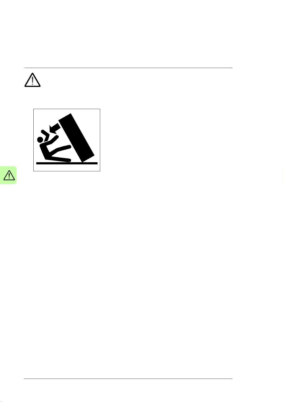
WARNING! Obey these instructions. If you ignore them, injury or death, or
damage to the equipment can occur.
• Secure the cabinet to the floor to prevent it from toppling over when you pull out drive
and LCL filter modules. The modules are heavy and have a high center of gravity.
• Wear protective gloves and long sleeves. Some parts have sharp edges.
• Beware of hot surfaces. Some parts, such as heatsinks of power semiconductors,
remain hot for a while after disconnection of the electrical supply.
• Beware of hot air exiting from the air outlets.
• Keep the drive in its package or protect it otherwise from dust and metal shavings from
drilling and grinding until you install it. Protect also the installed drive against dust and
metal shavings. Electrically conductive debris inside the drive can cause damage or
malfunction.
• Vacuum clean the area below the drive before the start-up to prevent the drive cooling
fan from drawing the dust inside the drive.
• Do not cover the air inlet and outlet when the drive is running.
• Make sure that there is sufficient cooling. See section Examining the installation site
(page 67).
• Keep the cabinet doors closed when the drive is powered. With the doors open, a risk
of a potentially fatal electric shock, arc flash or high-energy arc blast exists. If you
cannot avoid working on a powered drive, obey the local laws and regulations on live
working (including – but not limited to – electric shock and arc protection).
• Before you connect voltage to the drive, make sure that the cabinet doors are closed.
Keep the doors closed during operation.
• Before you adjust the drive operation limits, make sure that the motor and all driven
equipment can operate throughout the set operation limits.
• Before you activate the automatic fault reset or automatic restart functions of the drive
control program, make sure that no dangerous situations can occur. These functions
reset the drive automatically and continue operation after a fault or supply break. If
these functions are activated, the installation must be clearly marked as defined in
Safety instructions 17
2
IEC/EN 61800-5-1, subclause 6.5.3, for example, "THIS MACHINE STARTS
AUTOMATICALLY".
• The maximum number of drive power-ups is five in ten minutes. Too frequent power-
ups can damage the charging circuit of the DC capacitors.
• Make sure that any safety circuits (for example, emergency stop and Safe torque off)
are validated at start-up. See chapter The Safe torque off function (page 265). For
other safety functions, see their separate instructions.
• Handle the drive and LCL filter modules carefully:
• Use safety shoes with a metal toe cap to avoid foot injury.
• Lift the module with a lifting device only. Use the designated lifting points.
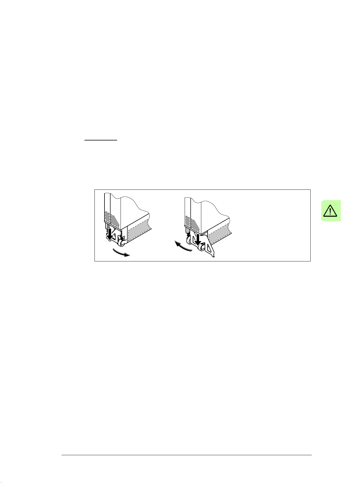
• Frame R11:
• Do not tilt the module. It is heavy and its center of gravity is high.
• Make sure that the module does not topple over when you move it on the
floor: Do not leave the module unattended on a sloping floor. Extend the
support legs: Press each leg a little down and turn it aside. Whenever
possible secure the module also with chains.
• Do not use the module installation ramp with plinth heights which exceed the
maximum height marked on the ramp. (The maximum plinth height is 50 mm
[1.97 in] when the telescopic ramp is fully retracted and 150 mm [5.91 in]
when the ramp is fully extended.)
• Secure the module installation ramp carefully.
18 Safety instructions
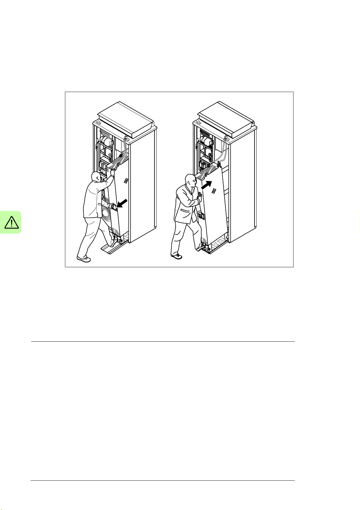
• To prevent the drive module from falling, attach its top lifting lugs with chains
to the cabinet frame before you push the module into the cabinet and pull it
from the cabinet. Work carefully preferably with help from another person.
Keep a constant pressure with one foot on the base of the module to prevent
the module from falling on its back.
Note:
• If you select an external source for the start command and it is on, the drive will start
immediately after fault reset unless you configure the drive for pulse start. See the
firmware manual.
• When the control location is not set to Local, the stop key on the control panel will not
stop the drive.
• Only authorized persons are allowed to repair a malfunctioning drive.

Safety instructions 19
Electrical safety in installation, start-up and maintenance
Electrical safety precautions
These warnings are for all personnel who do work on the drive, motor cable or motor.
WARNING! Obey these instructions. If you ignore them, injury or death, or
damage to the equipment can occur. If you are not a qualified electrical
professional, do not do installation or maintenance work. Go through these steps
before you begin any installation or maintenance work.
1. Keep the cabinet doors closed when the drive is powered. With the doors open, a risk
of electric shock and/or arcing exists.
2. Clearly identify the work location.
3. Disconnect all possible voltage sources.
• Open the main disconnecting device (Q1) of the drive. Open the disconnector of
the supply transformer as the main disconnecting device of the drive does not
remove the voltage from the input busbars or V-meter (option +G334) of the drive.
• Make sure that reconnection is not possible. Lock the disconnectors to open
position and attach a warning notice to them.
• Disconnect any external power sources from the control circuits before you do
work on the control cables.
• After you disconnect the drive, always wait for 5 minutes to let the intermediate
circuit capacitors discharge before you continue.
4. Protect any other energized parts in the work location against contact.
5. Take special precautions when close to bare conductors.
20 Safety instructions
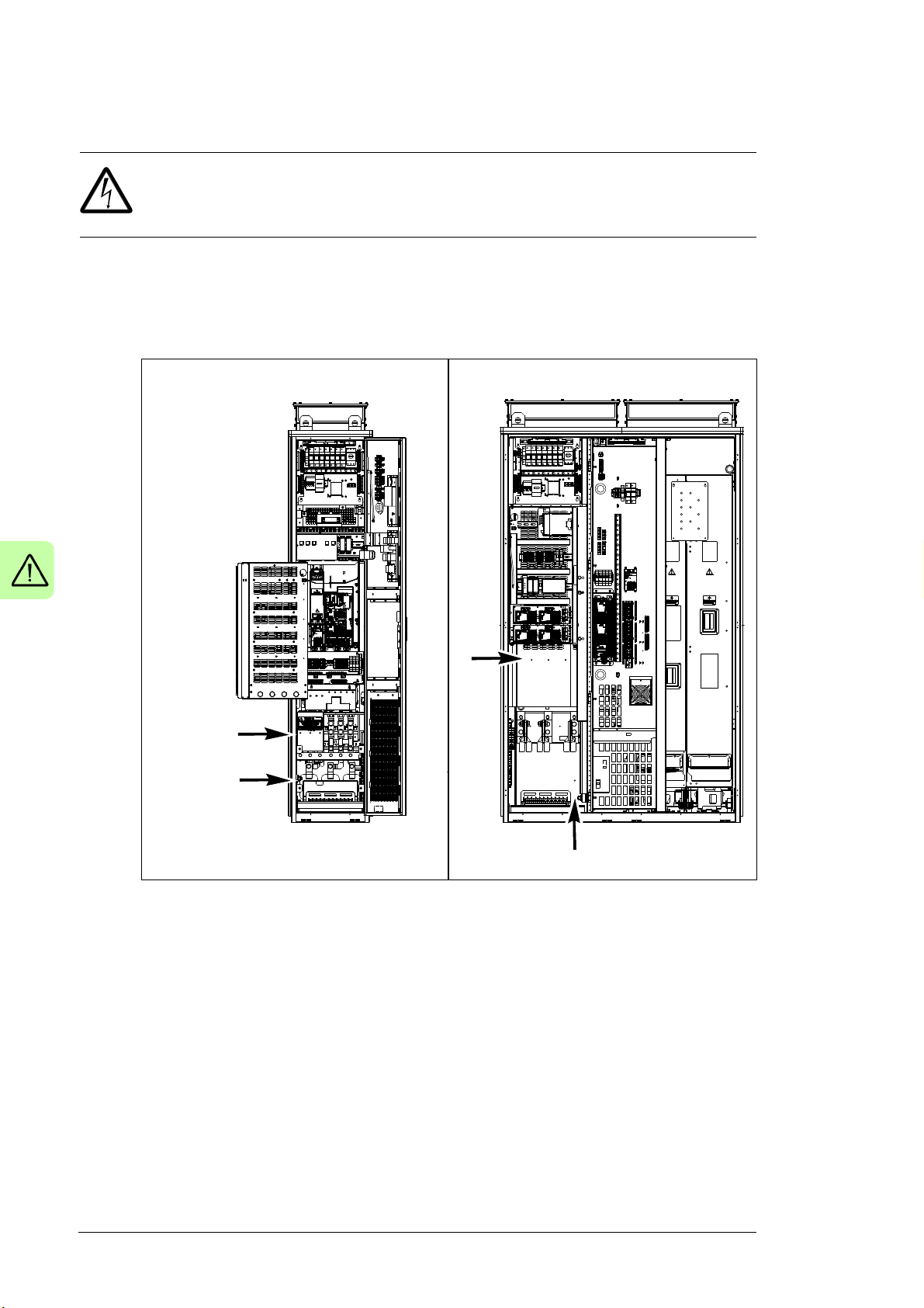
L1, L2, L3
PE
Frame R8
L1, L2,
L3
PE
Frame R11
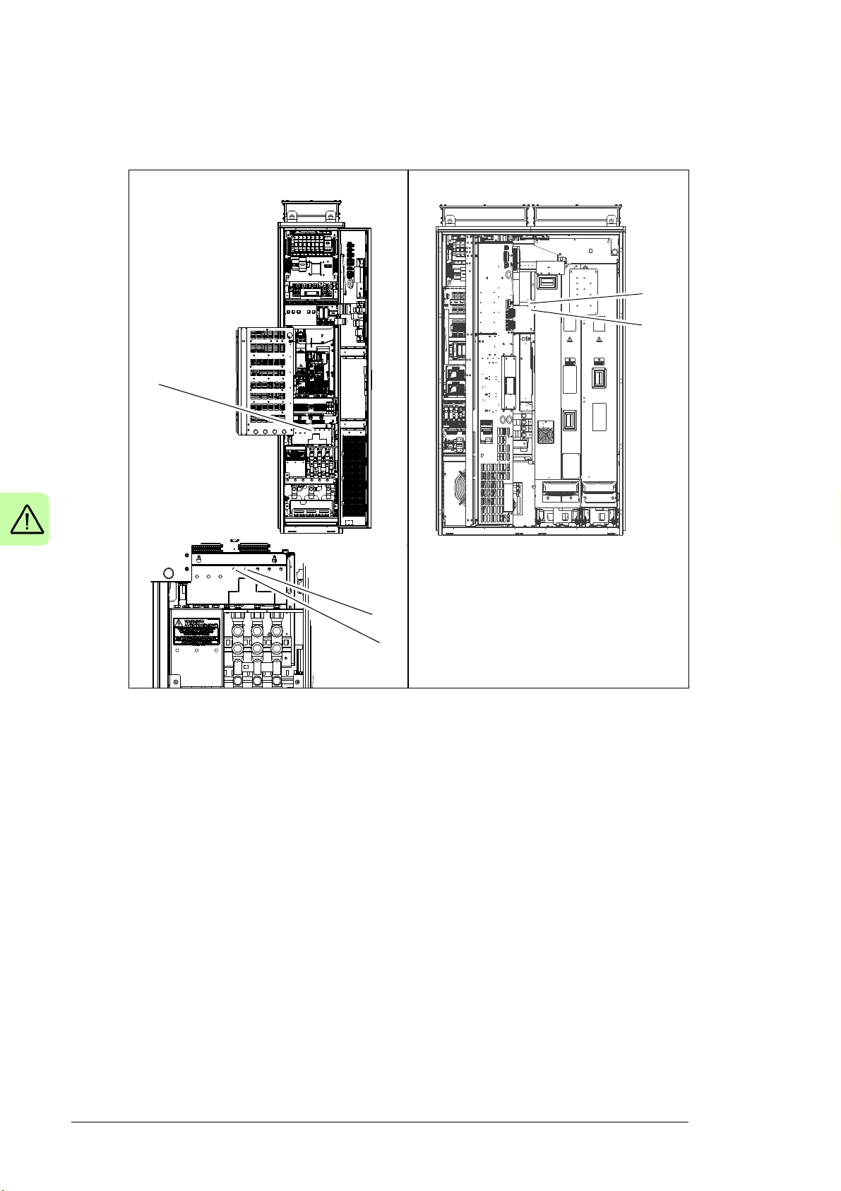
6. Measure that the installation is de-energized.
WARNING! If the measurement requires removal or disassembly of shrouding or
other cabinet structures, obey the local laws and regulations applicable to live
working (including – but not limited to – electric shock and arc protection).
• Use a multimeter with an impedance of at least 1 Mohm.
• Make sure that the voltage between the drive input power terminals (L1, L2, L3)
and the grounding (PE) busbar is close to 0 V. The measuring holes in the shroud
of the standard drive are shown below.
Safety instructions 21
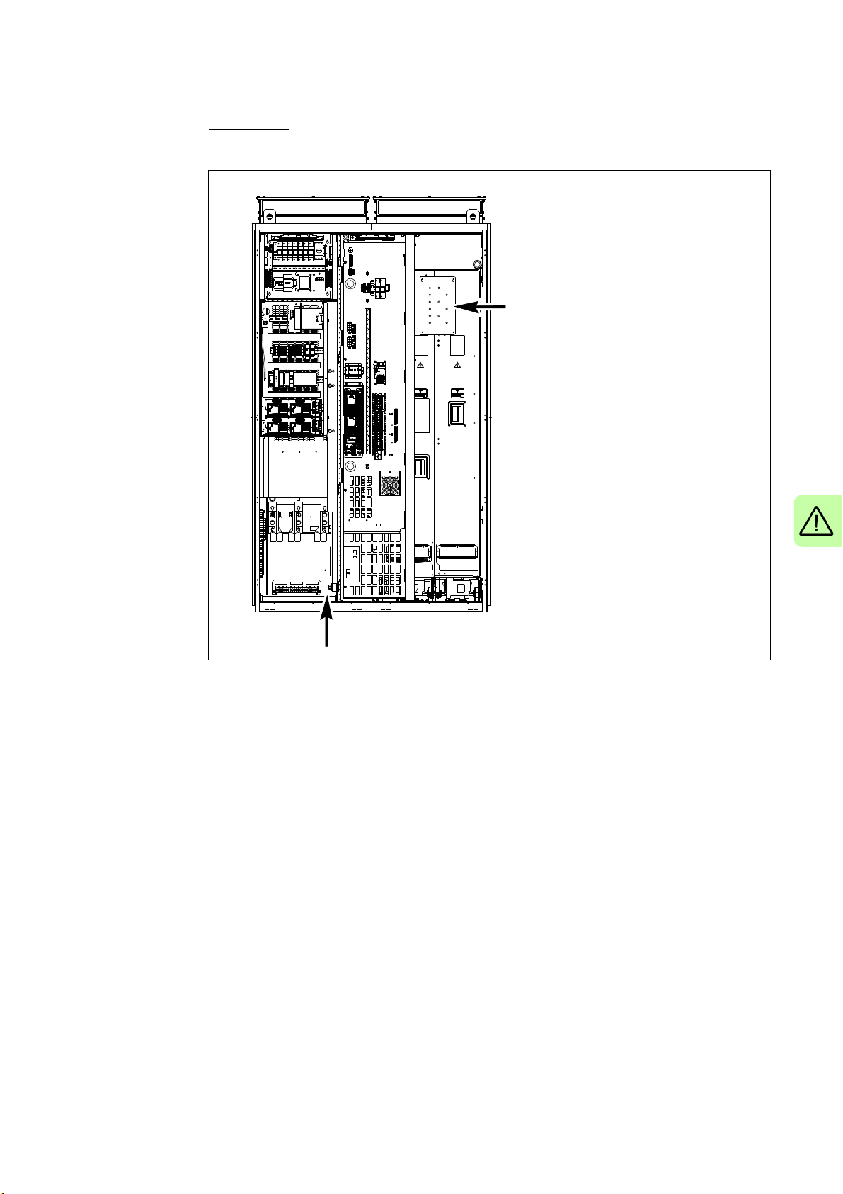
PE
AC busbars
• Frame R11: Make sure that the voltage of the drive AC busbars between the drive
module and the LCL filter and the grounding (PE) busbar are close to 0 V. The
measuring holes in the shroud of the standard drive are shown below.
22 Safety instructions
Frame R8
DC+
DC-
DC- and DC+
Frame R11
DC+
DC-
• Make sure that the voltage between the DC busbars is close to 0 V. You can
measure the voltage through the holes in the shroud.
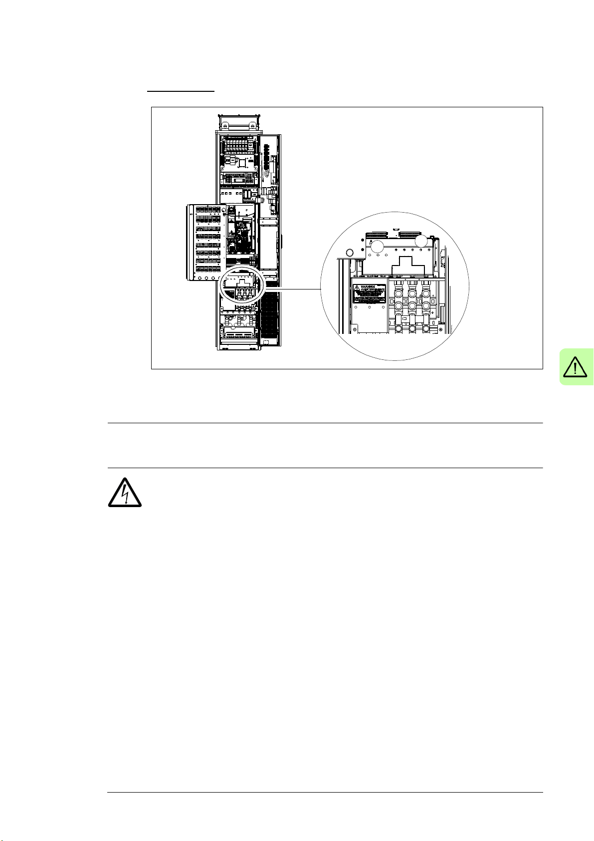
Safety instructions 23
a
b
• For frame R8, you can measure the voltage at the drive module input (a) and
output (b) terminals through the holes in the shroud.
7. Install temporary grounding as required by the local regulations. Connect the AC and
DC busbars to PE with a temporary grounding tool.
8. Ask the person in control of the electrical installation work for a permit to work.
Additional instructions and notes
WARNING! Obey these instructions. If you ignore them, injury or death, or
damage to the equipment can occur.
• If you are not a qualified electrical professional, do not do electrical installation or
maintenance work.
• Do not install a drive with an EMC filter (option +E202) on an IT (ungrounded) power
system or a high resistance-grounded (over 30 ohms) power system without
disconnecting the filter and/or the varistor screws.
• Do not connect the drive to a voltage higher than what is specified on the type
designation label. If you do, the brake chopper (option +D150) starts to operate which
causes overheating of the brake resistor (option +D151, if present). Overvoltage can
also cause the motor to rush to its maximum speed.
• We do not recommend that you secure the cabinet by arc welding. If you have to, obey
the instructions on page 80.
• Do not do insulation or voltage withstand tests on the drive or its modules.
Note:
• The motor cable terminals of the drive are at a dangerous voltage when the input
power is on, regardless of whether the motor is running or not.
• The DC bus, brake chopper and brake resistors (if any) are at a dangerous voltage.
• External wiring can supply dangerous voltages to the relay outputs of the control units
of the drive.
24 Safety instructions
• The Safe torque off function does not remove the voltage from the main and auxiliary
circuits. The function is not effective against deliberate sabotage or misuse.
WARNING! Use a grounding wrist band when you handle the printed circuit
boards. Do not touch the boards unnecessarily. The boards contain components
sensitive to electrostatic discharge.
WARNING! Obey these instructions. If you ignore them, equipment malfunction
and damage to the fiber optic cables can occur.
• Handle fiber optic cables with care.
• When you unplug the cables, always hold the connector, not the cable itself.
• Do not touch the ends of the fibers with bare hands as the ends are extremely
sensitive to dirt.
• Do not bend the fiber optic cables too tightly. The minimum allowed bend radius is
35 mm (1.4”).
Additional instruction for DC connection
WARNING! Do not connect the drive DC link to a common DC system. The drive
will get damaged.
Grounding
These instructions are for all personnel who are responsible for the grounding of the drive.
WARNING! Obey these instructions. If you ignore them, injury or death, or
equipment malfunction can occur, and electromagnetic interference can increase.
• If you are not a qualified electrical professional, do not do grounding work.
• Always ground the drive, the motor and adjoining equipment. This is necessary for the
personnel safety. Proper grounding also reduces electromagnetic emission and
interference.
• Make sure that the conductivity of the grounding conductors is sufficient. See section
Selecting the power cables (page 90). Obey the local regulations.
• Connect the power cable shields to protective earth (PE) of the drive to make sure of
personnel safety.
• Make a 360° grounding of the power and control cable shields at the cable entries to
suppress electromagnetic disturbances.
• In a multiple-drive installation, connect each drive separately to the protective earth
(PE) busbar of the switch board or the transformer.

Safety instructions 25
Note:
• You can use power cable shields as grounding conductors only when their conductivity
is sufficient.
• As the normal touch current of the drive is higher than 3.5 mA AC or 10 mA DC, you
must use a fixed protective earth (PE) connection. See standard EN 61800-5-1,
4.3.5.5.2.

26 Safety instructions
Additional instructions for permanent magnet motor drives
Safety in installation, start-up and maintenance
These are additional warnings concerning permanent magnet motor drives. The other
safety instructions in this chapter are also valid.
WARNING! Obey these instructions. If you ignore them, injury or death and
damage to the equipment can occur.
• Do not do work on the drive when the permanent magnet motor is rotating. A rotating
permanent magnet motor energizes the drive including its input power terminals.
Before installation, start-up and maintenance work on the drive:
• Stop the motor.
• Disconnect the motor from the drive with a safety switch or by other means.
• If you cannot disconnect the motor, make sure that the motor cannot rotate during
work. Make sure that no other system, like hydraulic crawling drives, can rotate the
motor directly or through any mechanical connection like felt, nip, rope, etc.
• Measure that the installation is de-energized.
• Use a multimeter with an impedance of at least 1 Mohm.
• Make sure that the voltage between the drive output terminals (U2, V2, W2) and
the grounding (PE) busbar is close to 0 V.
• Make sure that the voltage between the drive input power terminals (L1, L2, L3)
and the grounding (PE) busbar is close to 0 V.
• Make sure that the voltage between the plus and minus busbars of the drive DC
link and the grounding (PE) busbar is close to 0 V.
• Install temporary grounding to the drive output terminals (U2, V2, W2). Connect the
output terminals together as well as to the PE.
• Make sure that the operator cannot run the motor over the rated speed. Motor
overspeed causes overvoltage which can damage the capacitors in the intermediate
circuit of the drive.

Introduction to the manual 27
2
Introduction to the manual
Contents of this chapter
This chapter describes the manual. It contains a flowchart of steps in checking the
delivery, installing and starting up the drive. The flowchart refers to chapters/sections in
this manual and to other manuals.
Target audience
This manual is intended for people who plan the installation, install, start up, use and
service the drive. Read the manual before working on the drive. You are expected to know
the fundamentals of electricity, wiring, electrical components and electrical schematic
symbols.
The manual is written for readers worldwide. Both SI and imperial units are shown.
Contents of the manual
This manual contains the instructions and information for the basic drive configuration. The
chapters of the manual are briefly described below.
Safety instructions gives safety instructions for the installation, start-up, operation and
maintenance of the drive.
Introduction to the manual gives and introduction to this manual.
Operation principle and hardware description describes the operation principle and
construction of the drive.
Mechanical installation describes how to install the drive mechanically.
Guidelines for planning the electrical installation contains instructions for the motor and
cable selection, protections and cable routing.

28 Introduction to the manual
Electrical installation gives instructions on wiring the drive.
Control unit of frame R11 contains the default I/O connection diagrams, descriptions of the
terminals and technical data for the control unit of the drive.
Installation checklist contains a list for checking the mechanical and electrical installation
of the drive.
Start-up describes the start-up procedure of the drive.
Fault tracing describes the fault tracing possibilities of the drive.
Maintenance contains preventive maintenance instructions.
Technical data contains the technical specifications of the drive, for example, the ratings,
sizes and technical requirements, provisions for fulfilling the requirements for CE and other
markings.
Dimensions contains example dimension drawings of the drive.
The Safe torque off function describes the Safe torque off function of the drive and gives
instructions on its implementation.
Resistor braking describes selection, protection, wiring and start-up of optional brake
choppers (+D150) and resistors (+D151). The chapter also contains technical data.
Related documents
Drive hardware manuals and guides Code (English)
Drive/converter/inverter safety instructions Multilingual code:
ACS880-37 drives (45…400 kW) hardware manual 3AXD50000035159
ACx-AP-x assistant control panels user’s manual 3AUA0000085685
ACS880 frames R1 to R11 EMC filter and ground-to-phase varistor disconnecting
instructions
Drive firmware manuals and guides
ACS880 primary control program firmware manual 3AUA0000085967
Quick start-up guide for ACS880 drives with primary control program 3AUA0000098062
ACS880 IGBT supply control program firmware manual 3AUA0000131562
Option manuals and guides
Drive composer start-up and maintenance PC tool user’s manual 3AUA0000094606
Bypass connection for ACS880-07, -17, -37 (40...1200 A) option description 3AXD50000048959
FSO-12 safety functions module user’s manual 3AXD50000015612
FSO-21 safety functions module user’s manual 3AXD50000015614
User’s manual for Prevention of unexpected start-up (+Q950) for ACS880-07/17/37
drives
User’s manual for Emergency stop, stop category 0 (+Q951) for ACS880-07/17/37
drives
User’s manual for Emergency stop, stop category 1 (+Q952) for ACS880-07/17/37
drives
User’s manual for Prevention of unexpected start-up (+Q957) for ACS880-07/17/37
drives
User’s manual for Emergency stop, stop category 0 (+Q963) for ACS880-07/17/37
drives
User’s manual for Emergency stop, stop category 1 (+Q964) for ACS880-07/17/37
drives
User’s manual for Emergency stop, configurable stop category 0 or 1 (+Q978) for
ACS880-07/17/37 drives
3AXD50000037978
3AUA0000125152
3AUA0000145922
3AUA0000119895
3AUA0000119896
3AUA0000119910
3AUA0000119908
3AUA0000119909
3AUA0000145920

Introduction to the manual 29
ACS880-37 (45…400 kW, 60…450 hp) manuals
Manuals and quick guides for I/O extension modules, fieldbus adapter, etc.
You can find manuals and other product documents in PDF format on the Internet. See
section Document library on the Internet on the inside of the back cover. For manuals not
available in the Document library, contact your local ABB representative.
The code below opens an online listing of the manuals applicable to the product
:
Categorization by frame size and option code
Some instructions, technical data and dimension drawings which concern only certain
frame sizes are marked with the symbol of the frame size, for example R11. The frame
size is marked on the type designation label (see page 62).
The instructions, technical data and dimension drawings which only concern certain
optional selections are marked with option codes (such as +E205). The options included in
the drive can be identified from the option codes visible on the type designation label (see
page 62). The option selections are listed in section Type designation key (page 63).
30 Introduction to the manual
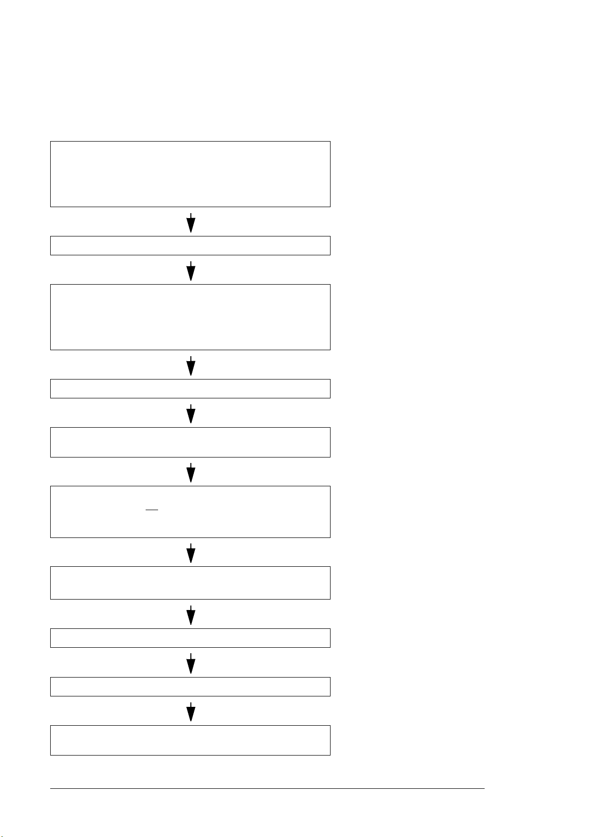
Quick installation, commissioning and operation flowchart
Task See
Plan the electrical installation and acquire the accessories needed
(cables, fuses, etc.).
Check the ratings, required cooling air flow, input power connection,
compatibility of the motor, motor connection, and other technical
data.
Check the installation site. Ambient conditions (page 232)
Unpack and check the drive (only intact units may be started up).
Make sure that all necessary optional modules and equipment are
present and correct.
Mount the drive.
Route the cables. Routing the cables (page 96)
Check the insulation of the supply cable, the motor and the motor
cable.
Guidelines for planning the
electrical installation (page 83)
Technical data (page 217)
Mechanical installation (page 67)
If the drive has been nonoperational for more than one year,
the DC link capacitors need to be
reformed (page 208)
Checking the insulation of the
assembly (page 105)
If the drive is about to be connected to an IT (ungrounded) system,
check that the drive is not
Connect the power cables.
Connect the control cables.
Check the installation. Installation checklist (page 161)
Start the drive up. Start-up (page 163)
Operate the drive: start, stop, speed control etc. Quick start-up guide, firmware
equipped with EMC filter (option +E202).
Checking the compatibility with IT
(ungrounded), corner-grounded
delta, midpoint-grounded delta and
TT systems (page 106)
Electrical installation (page 105)
manual
 Loading...