

Page 1
ABB industrial drives
User's manual
ACS880-1007LC liquid cooling unit
Page 2

Page 3
User's manual
ACS880-1007LC liquid cooling unit
Table of contents
3. Mechanical installation
4. Electrical installation
6. Start-up
© 2017 ABB Oy. All Rights Reserved. 3AXD50000129607 Rev A
EN
EFFECTIVE: 2017-12-22
Page 4

Page 5

Table of contents
1 Introduction to the manual
2 Operation basics and hardware description
Table of contents 5
11Contents of this chapter ...... . . .. . .. . . .. . . .. . . .. . .. . . .. . . .. . . .. . .. . . .. . . .. . . .. . .. . . .. . . .. . . .. . .. . .
11Applicability .. . . .. . .. . . .. . . .. . . .. . .. . . .. . . .. . . .. . .. . . .. . . .. . . .. . .. . . .. . . .. . . .. . .. . . .. . . .. . . .. . .. . . .. .
11Safety instructions . . . .. . .. . . .. . . .. . . .. . .. . . .. . . .. . . .. . .. . . .. . . .. . . .. . .. . . .. . . .. . . .. . .. . . .. . . .. . . .. .
11Target audience ... . . .. . . .. . . .. . .. . . .. . . .. . . .. . .. . . .. . . .. . . .. . .. . . .. . . .. . . .. . .. . . .. . . .. . . .. . .. . . .. . .
11Categorization by option code ...... . . .. . .. . . .. . . .. . . .. . .. . . .. . . .. . . .. . .. . . .. . . .. . . .. . .. . . .. . . .. .
12Use of component designations ...... . . .. . .. . . .. . . .. . . .. . .. . . .. . . .. . . .. . .. . . .. . . .. . . .. . .. . . .. . . .
12Terms and abbreviations ...... . . .. . .. . . .. . . .. . . .. . .. . . .. . . .. . . .. . .. . . .. . . .. . . .. . .. . . .. . . .. . . .. . .. .
12Related manuals . . .. . . .. . . .. . . .. . .. . . .. . . .. . . .. . .. . . .. . . .. . . .. . .. . . .. . . .. . .. . . .. . . .. . . .. . .. . . .. . . ..
12Related single drive manuals ...... . .. . . .. . . .. . . .. . .. . . .. . . .. . . .. . .. . . .. . . .. . . .. . .. . . .. . . .. . . .
13Contents of this chapter ...... . . .. . .. . . .. . . .. . . .. . .. . . .. . . .. . . .. . .. . . .. . . .. . . .. . .. . . .. . . .. . . .. . .. . .
13Basics .. . . .. . .. . . .. . . .. . .. . . .. . . .. . . .. . .. . . .. . . .. . . .. . .. . . .. . . .. . . .. . .. . . .. . . .. . . .. . .. . . .. . . .. . . .. . .. .
14Layout drawing – ACS880-1007LC-0070 in cabinet line-up .. . . .. . . .. . .. . . .. . . .. . . .. . .. . . .. .
15ACS880-1007LC-0070 component designations .... . . .. . . .. . . .. . .. . . .. . . .. . .. . . .. . . .. . . .
16Layout drawing – ACS880-1007LC-0195 in cabinet line-up .. . . .. . . .. . .. . . .. . . .. . . .. . .. . . .. .
18ACS880-1007LC-0195 component designations ... . . .. . . .. . . .. . . .. . .. . . .. . . .. . . .. . .. . . .. .
19Layout drawing – ACS880-1007LC-0195 stand-alone (option +C139) .. . . .. . . .. . . .. . .. . . .
20Swing out frame for electric devices in ACS880-1007LC-0070 ..... . . .. . .. . . .. . . .. . . .. . .. . .
21Swing out frame for electric devices in ACS880-1007LC-0195 ..... . . .. . .. . . .. . . .. . . .. . .. . .
22Control interfaces . . . .. . .. . . .. . . .. . . .. . .. . . .. . . .. . .. . . .. . . .. . . .. . .. . . .. . . .. . . .. . .. . . .. . . .. . . .. . .. . . .
22General .. . . .. . .. . . .. . . .. . . .. . .. . . .. . . .. . .. . . .. . . .. . . .. . .. . . .. . . .. . . .. . .. . . .. . . .. . . .. . .. . . .. . . .. . .
22Control panel . . .. . . .. . . .. . . .. . .. . . .. . . .. . . .. . .. . . .. . . .. . . .. . .. . . .. . . .. . .. . . .. . . .. . . .. . .. . . .. . . .. .
22IO interface of the control unit . .. . . .. . . .. . . .. . .. . . .. . . .. . . .. . .. . . .. . . .. . . .. . .. . . .. . . .. . . .. . .. .
23IO interface of the FAIO-01 analog interface module . .. . . .. . . .. . .. . . .. . . .. . .. . . .. . . .. . . ..
23Use of the control unit expansion slots .. . . .. . . .. . .. . . .. . . .. . .. . . .. . . .. . . .. . .. . . .. . . .. . . .. . ..
23PC connection . . .. . . .. . . .. . . .. . .. . . .. . . .. . . .. . .. . . .. . . .. . . .. . .. . . .. . . .. . . .. . .. . . .. . . .. . . .. . .. . . .
24Type designation label .. . .. . . .. . .. . . .. . . .. . . .. . .. . . .. . . .. . . .. . .. . . .. . . .. . . .. . .. . . .. . . .. . .. . . .. . . ..
24Type designation key .. . .. . . .. . .. . . .. . . .. . . .. . .. . . .. . . .. . .. . . .. . . .. . . .. . .. . . .. . . .. . . .. . .. . . .. . . .. . .
24Basic code . . .. . . .. . . .. . . .. . .. . . .. . . .. . .. . . .. . . .. . . .. . .. . . .. . . .. . . .. . .. . . .. . . .. . . .. . .. . . .. . . .. . . ..
24Option codes . . .. . . .. . . .. . . .. . .. . . .. . . .. . . .. . .. . . .. . . .. . . .. . .. . . .. . . .. . . .. . .. . . .. . . .. . .. . . .. . . .. .
3 Mechanical installation
4 Electrical installation
29What this chapter contains ...... . . .. . .. . . .. . . .. . . .. . .. . . .. . . .. . . .. . .. . . .. . . .. . . .. . .. . . .. . . .. . . .. .
29Safety .. . . .. . .. . . .. . . .. . . .. . .. . . .. . . .. . . .. . .. . . .. . . .. . . .. . .. . . .. . . .. . . .. . .. . . .. . . .. . . .. . .. . . .. . . .. . .. .
29Electrical safety precautions ... . . .. . . .. . . .. . . .. . .. . . .. . . .. . .. . . .. . . .. . . .. . .. . . .. . . .. . . .. . .. . . .
30Connecting the power cables ...... . . .. . .. . . .. . . .. . . .. . .. . . .. . . .. . .. . . .. . . .. . . .. . .. . . .. . . .. . . .. . .
31Connection diagram – pump motors, auxiliary circuit and cubicle heater .. . . .. . . .. . .. .
31Connecting the control cables ...... . . .. . .. . . .. . . .. . . .. . .. . . .. . . .. . . .. . .. . . .. . . .. . . .. . .. . . .. . . .. .
32Control cable connection procedure ...... . . .. . .. . . .. . . .. . . .. . .. . . .. . . .. . . .. . .. . . .. . . .. . . .. . .
32Grounding the outer shields of the control cables at the cabinet entry ... . . .. . . .. . .
34Routing the control cables inside the cabinet .. . . .. . . .. . .. . . .. . . .. . . .. . .. . . .. . . .. . . .. . ..
34Connecting control cabling ... . . .. . . .. . . .. . .. . . .. . . .. . . .. . .. . . .. . . .. . .. . . .. . . .. . . .. . .. . . .. .
Page 6

6 Table of contents
5 Installation checklist
6 Start-up
7 Maintenance
39Contents of this chapter ...... . . .. . .. . . .. . . .. . . .. . .. . . .. . . .. . . .. . .. . . .. . . .. . . .. . .. . . .. . . .. . . .. . .. . .
39Safety .. . . .. . .. . . .. . . .. . . .. . .. . . .. . . .. . . .. . .. . . .. . . .. . . .. . .. . . .. . . .. . . .. . .. . . .. . . .. . . .. . .. . . .. . . .. . .. .
39Before start-up . . . .. . .. . . .. . . .. . . .. . .. . . .. . . .. . . .. . .. . . .. . . .. . .. . . .. . . .. . . .. . .. . . .. . . .. . . .. . .. . . .. . .
40Adjusting air pressure of the expansion tank .. . . .. . . .. . .. . . .. . . .. . . .. . .. . . .. . . .. . . .. . .. . . .. . . .
40About the expansion tank ...... . . .. . .. . . .. . . .. . . .. . .. . . .. . . .. . . .. . .. . . .. . . .. . . .. . .. . . .. . . .. . . .
40Pressure adjusting procedure ... . . .. . . .. . . .. . .. . . .. . . .. . . .. . .. . . .. . . .. . .. . . .. . . .. . . .. . .. . . .. .
41Filling up the cooling circuit and starting the cooling unit .. . . .. . . .. . .. . . .. . . .. . . .. . .. . . .. . . ..
42Basic settings in the control program . .. . . .. . . .. . .. . . .. . . .. . . .. . .. . . .. . . .. . . .. . .. . . .. . . .. . . .. . ..
43On-load settings . . . .. . .. . . .. . . .. . .. . . .. . . .. . . .. . .. . . .. . . .. . . .. . .. . . .. . . .. . . .. . .. . . .. . . .. . . .. . .. . . .. .
45Safety .. . . .. . .. . . .. . . .. . . .. . .. . . .. . . .. . . .. . .. . . .. . . .. . . .. . .. . . .. . . .. . . .. . .. . . .. . . .. . . .. . .. . . .. . . .. . .. .
45Maintenance intervals . . .. . . .. . . .. . . .. . .. . . .. . . .. . . .. . .. . . .. . . .. . . .. . .. . . .. . . .. . . .. . .. . . .. . . .. . . .. .
46Adding cooling liquid ... . . .. . . .. . .. . . .. . . .. . . .. . .. . . .. . . .. . . .. . .. . . .. . . .. . . .. . .. . . .. . . .. . . .. . .. . . ..
46Draining the cooling unit ...... . . .. . .. . . .. . . .. . . .. . .. . . .. . . .. . .. . . .. . . .. . . .. . .. . . .. . . .. . . .. . .. . . .. .
47Storing the cooling unit ...... . . .. . .. . . .. . . .. . . .. . .. . . .. . . .. . . .. . .. . . .. . . .. . . .. . .. . . .. . . .. . . .. . .. . . .
47Checking the quality of the coolant . .. . . .. . . .. . . .. . .. . . .. . . .. . .. . . .. . . .. . . .. . .. . . .. . . .. . . .. . .. . . .
47Cleaning and drying the leakage detector . .. . . .. . . .. . .. . . .. . . .. . . .. . .. . . .. . . .. . . .. . .. . . .. . . .. . .
48ACS880-1007LC-0070 replacing the pump motor .. . .. . .. . . .. . . .. . . .. . .. . . .. . . .. . . .. . .. . . .. . .
51ACS880-1007LC-0070 replacing the pump ...... . . .. . . .. . .. . . .. . . .. . . .. . .. . . .. . . .. . .. . . .. . . .. .
53ACS880-1007LC-0195 replacing the pump motor .. . .. . .. . . .. . . .. . . .. . .. . . .. . . .. . . .. . .. . . .. . .
55ACS880-1007LC-0195 replacing the pump ...... . . .. . . .. . .. . . .. . . .. . . .. . .. . . .. . . .. . .. . . .. . . .. .
8 Program features
57What this chapter contains ...... . . .. . .. . . .. . . .. . . .. . .. . . .. . . .. . . .. . .. . . .. . . .. . . .. . .. . . .. . . .. . . .. .
57Basics .. . . .. . .. . . .. . . .. . .. . . .. . . .. . . .. . .. . . .. . . .. . . .. . .. . . .. . . .. . . .. . .. . . .. . . .. . . .. . .. . . .. . . .. . . .. . .. .
57Start/stop control, and reset ...... . . .. . . .. . .. . . .. . . .. . . .. . .. . . .. . . .. . . .. . .. . . .. . . .. . . .. . .. . . .. . . ..
57Settings and diagnostics ... . . .. . . .. . . .. . .. . . .. . . .. . . .. . .. . . .. . . .. . . .. . .. . . .. . . .. . . .. . .. . . .. . . .
58Pump control . . .. . . .. . . .. . . .. . .. . . .. . . .. . . .. . .. . . .. . . .. . . .. . .. . . .. . . .. . . .. . .. . . .. . . .. . .. . . .. . . .. . . ..
58Basic operation . . .. . . .. . . .. . . .. . .. . . .. . . .. . . .. . .. . . .. . . .. . . .. . .. . . .. . . .. . . .. . .. . . .. . . .. . . .. . .. . .
58Settings and diagnostics ... . . .. . . .. . . .. . .. . . .. . . .. . . .. . .. . . .. . . .. . . .. . .. . . .. . . .. . . .. . .. . . ..
58Alternation .. . . .. . . .. . .. . . .. . . .. . .. . . .. . . .. . . .. . .. . . .. . . .. . . .. . .. . . .. . . .. . . .. . .. . . .. . . .. . . .. . .. . . .
58Settings and diagnostics ... . . .. . . .. . . .. . .. . . .. . . .. . . .. . .. . . .. . . .. . . .. . .. . . .. . . .. . . .. . .. . . ..
58Redundancy .. . . .. . .. . . .. . . .. . .. . . .. . . .. . . .. . .. . . .. . . .. . . .. . .. . . .. . . .. . . .. . .. . . .. . . .. . . .. . .. . . .. .
58Settings and diagnostics ... . . .. . . .. . . .. . .. . . .. . . .. . . .. . .. . . .. . . .. . . .. . .. . . .. . . .. . . .. . .. . . ..
59Standby .. . . .. . .. . . .. . . .. . . .. . .. . . .. . . .. . . .. . .. . . .. . . .. . . .. . .. . . .. . . .. . .. . . .. . . .. . . .. . .. . . .. . . .. . .
59Settings and diagnostics ... . . .. . . .. . . .. . .. . . .. . . .. . . .. . .. . . .. . . .. . . .. . .. . . .. . . .. . . .. . .. . . ..
59Delayed cooling . . .. . . .. . . .. . . .. . .. . . .. . . .. . .. . . .. . . .. . . .. . .. . . .. . . .. . . .. . .. . . .. . . .. . . .. . .. . . .. . .
59Settings and diagnostics ... . . .. . . .. . . .. . .. . . .. . . .. . . .. . .. . . .. . . .. . . .. . .. . . .. . . .. . . .. . .. . . ..
59Pressure monitoring functions ... . . .. . . .. . . .. . .. . . .. . . .. . . .. . .. . . .. . . .. . . .. . .. . . .. . . .. . . .. . .. . . ..
59Operation of the Pressure difference monitoring function .... . . .. . . .. . . .. . .. . . .. . . .. . . .. .
60Settings and diagnostics ... . . .. . . .. . . .. . .. . . .. . . .. . . .. . .. . . .. . . .. . . .. . .. . . .. . . .. . . .. . .. . . .. . . .
60Temperature monitoring functions ...... . . .. . . .. . . .. . .. . . .. . . .. . . .. . .. . . .. . . .. . . .. . .. . . .. . . .. . .. .
60Settings and diagnostics ... . . .. . . .. . . .. . .. . . .. . . .. . . .. . .. . . .. . . .. . . .. . .. . . .. . . .. . . .. . .. . . .. . . .
60Leakage monitoring function ... . . .. . . .. . . .. . .. . . .. . . .. . . .. . .. . . .. . . .. . . .. . .. . . .. . . .. . . .. . .. . . .. . .
60Settings and diagnostics ... . . .. . . .. . . .. . .. . . .. . . .. . . .. . .. . . .. . . .. . . .. . .. . . .. . . .. . . .. . .. . . .. . . .
Page 7

9 Parameters
Table of contents 7
61Miscellaneous .. . . .. . .. . . .. . . .. . .. . . .. . . .. . . .. . .. . . .. . . .. . . .. . .. . . .. . . .. . . .. . .. . . .. . . .. . . .. . .. . . .. . .
61User lock . . .. . . .. . . .. . .. . . .. . . .. . . .. . .. . . .. . . .. . . .. . .. . . .. . . .. . . .. . .. . . .. . . .. . . .. . .. . . .. . . .. . .. . . .
61Settings and diagnostics ... . . .. . . .. . . .. . .. . . .. . . .. . . .. . .. . . .. . . .. . . .. . .. . . .. . . .. . . .. . .. . . ..
63Terms and abbreviations ...... . . .. . .. . . .. . . .. . . .. . .. . . .. . . .. . . .. . .. . . .. . . .. . . .. . .. . . .. . . .. . . .. . .. .
6301 Actual values ... . . .. . . .. . .. . . .. . . .. . . .. . .. . . .. . . .. . . .. . .. . . .. . . .. . . .. . .. . . .. . . .. . . .. . .. . . .. . . .. . .
6404 Warnings and faults . . . .. . .. . . .. . . .. . . .. . .. . . .. . . .. . . .. . .. . . .. . . .. . . .. . .. . . .. . . .. . . .. . .. . . .. . . ..
6606 Control and status words .. .. . . .. . . .. . . .. . .. . . .. . . .. . .. . . .. . . .. . . .. . .. . . .. . . .. . . .. . .. . . .. . . .. .
6707 System info ... . . .. . . .. . .. . . .. . . .. . . .. . .. . . .. . . .. . . .. . .. . . .. . . .. . . .. . .. . . .. . . .. . . .. . .. . . .. . . .. . . .
6720 LCU control and settings .. .. . . .. . . .. . . .. . .. . . .. . . .. . .. . . .. . . .. . . .. . .. . . .. . . .. . . .. . .. . . .. . . .. . .
6931 Fault functions ... . . .. . . .. . . .. . .. . . .. . . .. . . .. . .. . . .. . . .. . . .. . .. . . .. . . .. . .. . . .. . . .. . . .. . .. . . .. . . ..
7047 Data storage ... . . .. . . .. . .. . . .. . . .. . . .. . .. . . .. . . .. . . .. . .. . . .. . . .. . . .. . .. . . .. . . .. . . .. . .. . . .. . . .. . .
7049 Panel port communication ...... . . .. . .. . . .. . . .. . . .. . .. . . .. . . .. . . .. . .. . . .. . . .. . . .. . .. . . .. . . .. . .
7150 Fieldbus adapter (FBA) ...... . . .. . . .. . .. . . .. . . .. . .. . . .. . . .. . . .. . .. . . .. . . .. . . .. . .. . . .. . . .. . . .. .
7651 FBA A settings ...... . . .. . . .. . .. . . .. . . .. . .. . . .. . . .. . . .. . .. . . .. . . .. . . .. . .. . . .. . . .. . . .. . .. . . .. . . .. .
7852 FBA A data in .. .. . . .. . . .. . . .. . .. . . .. . . .. . . .. . .. . . .. . . .. . . .. . .. . . .. . . .. . .. . . .. . . .. . . .. . .. . . .. . . ..
7953 FBA A data out .. .. . . .. . . .. . . .. . .. . . .. . . .. . . .. . .. . . .. . . .. . . .. . .. . . .. . . .. . . .. . .. . . .. . . .. . . .. . .. . .
7954 FBA B settings ...... . . .. . . .. . .. . . .. . . .. . .. . . .. . . .. . . .. . .. . . .. . . .. . . .. . .. . . .. . . .. . . .. . .. . . .. . . .. .
8155 FBA B data in .. .. . . .. . . .. . . .. . .. . . .. . . .. . . .. . .. . . .. . . .. . . .. . .. . . .. . . .. . .. . . .. . . .. . . .. . .. . . .. . . ..
8256 FBA B data out .. .. . . .. . . .. . . .. . .. . . .. . . .. . . .. . .. . . .. . . .. . . .. . .. . . .. . . .. . . .. . .. . . .. . . .. . . .. . .. . .
8260 DDCS communication ... . . .. . . .. . .. . . .. . . .. . . .. . .. . . .. . . .. . . .. . .. . . .. . . .. . . .. . .. . . .. . . .. . . .. . .
8461 D2D and DDCS transmit data . .. . . .. . . .. . .. . . .. . . .. . . .. . .. . . .. . . .. . . .. . .. . . .. . . .. . . .. . .. . . .. .
8562 D2D and DDCS receive data . .. . . .. . .. . . .. . . .. . . .. . .. . . .. . . .. . . .. . .. . . .. . . .. . . .. . .. . . .. . . .. . .
8796 System . . .. . . .. . . .. . . .. . .. . . .. . . .. . . .. . .. . . .. . . .. . . .. . .. . . .. . . .. . .. . . .. . . .. . . .. . .. . . .. . . .. . . .. . .. .
10 Fault tracing
11 Fieldbus control through a fieldbus adapter
91What this chapter contains ...... . . .. . .. . . .. . . .. . . .. . .. . . .. . . .. . . .. . .. . . .. . . .. . . .. . .. . . .. . . .. . . .. .
91Safety .. . . .. . .. . . .. . . .. . . .. . .. . . .. . . .. . . .. . .. . . .. . . .. . . .. . .. . . .. . . .. . . .. . .. . . .. . . .. . . .. . .. . . .. . . .. . .. .
91Indications .. . . .. . .. . . .. . . .. . . .. . .. . . .. . . .. . . .. . .. . . .. . . .. . . .. . .. . . .. . . .. . . .. . .. . . .. . . .. . .. . . .. . . .. . . .
91Warnings and faults ....... . . .. . . .. . .. . . .. . . .. . . .. . .. . . .. . . .. . . .. . .. . . .. . . .. . .. . . .. . . .. . . .. . .. . .
92Editable messages . . .. . . .. . . .. . . .. . .. . . .. . . .. . . .. . .. . . .. . . .. . . .. . .. . . .. . . .. . . .. . .. . . .. . . .. . . .. .
92Warning/fault history and analysis .. . . .. . . .. . .. . . .. . . .. . . .. . .. . . .. . . .. . . .. . .. . . .. . . .. . .. . . .. . . .. .
92Event logs . . .. . . .. . . .. . . .. . .. . . .. . . .. . . .. . .. . . .. . . .. . . .. . .. . . .. . . .. . . .. . .. . . .. . . .. . .. . . .. . . .. . . ..
92Factory data logger ... . . .. . . .. . . .. . .. . . .. . . .. . .. . . .. . . .. . . .. . .. . . .. . . .. . . .. . .. . . .. . . .. . . .. . .
92Other data loggers ... . . .. . . .. . . .. . .. . . .. . . .. . .. . . .. . . .. . . .. . .. . . .. . . .. . . .. . .. . . .. . . .. . . .. . .. . . .
92User data logger ... . . .. . . .. . .. . . .. . . .. . . .. . .. . . .. . . .. . . .. . .. . . .. . . .. . .. . . .. . . .. . . .. . .. . . .. . .
92Parameters that contain warning/fault information .. . .. . . .. . . .. . .. . . .. . . .. . . .. . .. . . .. . . .. .
92QR Code generation for mobile service application .. . . .. . . .. . .. . . .. . . .. . . .. . .. . . .. . . .. . . .. . .
93Warnings .. . . .. . .. . . .. . . .. . . .. . .. . . .. . . .. . . .. . .. . . .. . . .. . .. . . .. . . .. . . .. . .. . . .. . . .. . . .. . .. . . .. . . .. . . ..
96Faults .. . . .. . .. . . .. . . .. . . .. . .. . . .. . . .. . . .. . .. . . .. . . .. . . .. . .. . . .. . . .. . .. . . .. . . .. . . .. . .. . . .. . . .. . . .. . .. .
97What this chapter contains ...... . . .. . .. . . .. . . .. . . .. . .. . . .. . . .. . . .. . .. . . .. . . .. . . .. . .. . . .. . . .. . . .. .
97System overview . . .. . . .. . . .. . . .. . .. . . .. . . .. . . .. . .. . . .. . . .. . . .. . .. . . .. . . .. . . .. . .. . . .. . . .. . .. . . .. . . ..
98Basics of the fieldbus control interface . .. . . .. . . .. . . .. . .. . . .. . . .. . . .. . .. . . .. . . .. . . .. . .. . . .. . . .. .
100Control word and Status word .. .. . . .. . . .. . . .. . .. . . .. . . .. . . .. . .. . . .. . . .. . . .. . .. . . .. . . .. . . .. . ..
100Debugging the network words ...... . . .. . .. . . .. . . .. . . .. . .. . . .. . . .. . . .. . .. . . .. . . .. . .. . . .. . .
100Actual values . . .. . . .. . . .. . . .. . .. . . .. . . .. . . .. . .. . . .. . . .. . . .. . .. . . .. . . .. . . .. . .. . . .. . . .. . . .. . .. . . .. .
100Debugging the network words ...... . . .. . .. . . .. . . .. . . .. . .. . . .. . . .. . . .. . .. . . .. . . .. . .. . . .. . .
100Setting up the cooling unit for fieldbus control ..... . . .. . .. . . .. . . .. . . .. . .. . . .. . . .. . . .. . .. . . .. . . .
Page 8

8 Table of contents
12 Internal cooling circuit
101Contents of this chapter ...... . . .. . .. . . .. . . .. . . .. . .. . . .. . . .. . . .. . .. . . .. . . .. . . .. . .. . . .. . . .. . . .. . .. . .
101Applicability .. . . .. . .. . . .. . . .. . . .. . .. . . .. . . .. . . .. . .. . . .. . . .. . . .. . .. . . .. . . .. . . .. . .. . . .. . . .. . . .. . .. . . .. .
101Internal cooling system ... . . .. . . .. . . .. . .. . . .. . . .. . . .. . .. . . .. . . .. . . .. . .. . . .. . . .. . .. . . .. . . .. . . .. . .. . .
102Connection to a cooling unit .. .. . . .. . . .. . . .. . .. . . .. . . .. . . .. . .. . . .. . . .. . . .. . .. . . .. . . .. . . .. . .. . . .. . .
102Connection to an ACS880-1007LC cooling unit . .. . . .. . . .. . . .. . .. . . .. . . .. . . .. . .. . . .. . . .. . .
103Connection to a custom cooling unit . .. . . .. . . .. . .. . . .. . . .. . . .. . .. . . .. . . .. . . .. . .. . . .. . . .. . . .. .
103General requirements . . . .. . .. . . .. . . .. . .. . . .. . . .. . . .. . .. . . .. . . .. . . .. . .. . . .. . . .. . . .. . .. . . .. . .
103Coolant temperature control ... . . .. . . .. . . .. . .. . . .. . . .. . . .. . .. . . .. . . .. . . .. . .. . . .. . . .. . . .. . ..
103Filling up and bleeding the internal cooling circuit .... . . .. . . .. . . .. . . .. . .. . . .. . . .. . . .. . .. . . .. . .
103Drive line-ups with an ACS880-1007LC cooling unit .. . . .. . . .. . .. . . .. . . .. . . .. . .. . . .. . . .. . .
103Drive line-ups with a custom cooling unit .. . . .. . .. . . .. . . .. . . .. . .. . . .. . . .. . . .. . .. . . .. . . .. . . ..
104Draining the internal cooling circuit .. .. . . .. . . .. . . .. . .. . . .. . . .. . . .. . .. . . .. . . .. . . .. . .. . . .. . . .. . . .. .
105Maintenance intervals . . . .. . .. . . .. . . .. . .. . . .. . . .. . . .. . .. . . .. . . .. . . .. . .. . . .. . . .. . . .. . .. . . .. . . .. . . .. .
105Technical data ... . . .. . . .. . . .. . .. . . .. . . .. . . .. . .. . . .. . . .. . . .. . .. . . .. . . .. . . .. . .. . . .. . . .. . . .. . .. . . .. . . ..
105Coolant specification . . . .. . .. . . .. . . .. . . .. . .. . . .. . . .. . . .. . .. . . .. . . .. . . .. . .. . . .. . . .. . .. . . .. . . .. . . .
105Coolant type . . .. . . .. . . .. . . .. . .. . . .. . . .. . . .. . .. . . .. . . .. . . .. . .. . . .. . . .. . . .. . .. . . .. . . .. . . .. . .. . .
105Temperature limits ... . . .. . . .. . . .. . . .. . .. . . .. . . .. . . .. . .. . . .. . . .. . .. . . .. . . .. . . .. . .. . . .. . . .. . . .. . ..
107Pressure limits . . .. . . .. . . .. . . .. . .. . . .. . . .. . . .. . .. . . .. . . .. . . .. . .. . . .. . . .. . . .. . .. . . .. . . .. . . .. . .. . . .
107Cooling circuit materials ... . . .. . . .. . . .. . .. . . .. . . .. . . .. . .. . . .. . . .. . .. . . .. . . .. . . .. . .. . . .. . . .. . . ..
13 Technical data
109What this chapter contains ...... . . .. . . .. . .. . . .. . . .. . .. . . .. . . .. . . .. . .. . . .. . . .. . . .. . .. . . .. . . .. . . .. .
109Nominal cooling power, losses and pressure drop . .. . .. . . .. . . .. . . .. . .. . . .. . . .. . . .. . .. . . .. . . ..
109Dimensions .. . . .. . .. . . .. . . .. . . .. . .. . . .. . . .. . .. . . .. . . .. . . .. . .. . . .. . . .. . . .. . .. . . .. . . .. . . .. . .. . . .. . . .. .
110Coolant flow and quantity ...... . . .. . .. . . .. . . .. . . .. . .. . . .. . . .. . . .. . .. . . .. . . .. . . .. . .. . . .. . . .. . . .. . ..
110Pump and motor types, and motor ratings .. . . .. . . .. . .. . . .. . . .. . . .. . .. . . .. . . .. . . .. . .. . . .. . . .. . .
110Filling pump . . .. . . .. . . .. . . .. . .. . . .. . . .. . . .. . .. . . .. . . .. . . .. . .. . . .. . . .. . . .. . .. . . .. . . .. . .. . . .. . . .. . . .. . .
110Fill/drain/bleed hoses . . . .. . .. . . .. . . .. . . .. . .. . . .. . . .. . . .. . .. . . .. . . .. . . .. . .. . . .. . . .. . . .. . .. . . .. . . .. . .
110Auxiliary power supply for the control circuits .. . . .. . . .. . .. . . .. . . .. . . .. . .. . . .. . . .. . . .. . .. . . .. . .
111Power supply for the cabinet heater (option +G300) ..... . . .. . .. . . .. . . .. . . .. . .. . . .. . . .. . . .. . .
111Flanges for connecting the piping .. . .. . .. . . .. . . .. . .. . . .. . . .. . . .. . .. . . .. . . .. . . .. . .. . . .. . . .. . . .. . .
111Ambient conditions . . . .. . .. . . .. . . .. . . .. . .. . . .. . . .. . . .. . .. . . .. . . .. . .. . . .. . . .. . . .. . .. . . .. . . .. . . .. . .. .
111Internal cooling circuit data ...... . . .. . .. . . .. . . .. . . .. . .. . . .. . . .. . . .. . .. . . .. . . .. . . .. . .. . . .. . . .. . . .. .
111External cooling circuit data ...... . . .. . .. . . .. . . .. . . .. . .. . . .. . . .. . . .. . .. . . .. . . .. . . .. . .. . . .. . . .. . . ..
111Liquid quality for standard heat exchanger and piping .... . . .. . . .. . . .. . . .. . .. . . .. . . .. . . ..
112Temperature and pressure limits .. . .. . .. . . .. . . .. . . .. . .. . . .. . . .. . . .. . .. . . .. . . .. . . .. . .. . . .. . . ..
112Recommended pipe size and material .. .. . . .. . . .. . .. . . .. . . .. . . .. . .. . . .. . . .. . . .. . .. . . .. . . .. .
112Materials .. . . .. . .. . . .. . . .. . . .. . .. . . .. . . .. . . .. . .. . . .. . . .. . .. . . .. . . .. . . .. . .. . . .. . . .. . . .. . .. . . .. . . .. . . .. .
113Compliance with the Pressure Equipment Directive (PED) .. . . .. . . .. . . .. . .. . . .. . . .. . . .. . .. . .
113Disclaimers .. . . .. . .. . . .. . . .. . .. . . .. . . .. . . .. . .. . . .. . . .. . . .. . .. . . .. . . .. . . .. . .. . . .. . . .. . . .. . .. . . .. . . .. .
113Generic disclaimer . . .. . . .. . . .. . . .. . .. . . .. . . .. . . .. . .. . . .. . . .. . . .. . .. . . .. . . .. . . .. . .. . . .. . . .. . .. . .
113Cybersecurity disclaimer . . .. . . .. . . .. . . .. . .. . . .. . . .. . . .. . .. . . .. . . .. . . .. . .. . . .. . . .. . . .. . .. . . .. . .
14 Piping and instrumentation diagrams
116ACS880-1007LC-0070 .. . . .. . . .. . .. . . .. . . .. . . .. . .. . . .. . . .. . . .. . .. . . .. . . .. . .. . . .. . . .. . . .. . .. . . .. . . .
117ACS880-1007LC-0070 component designations .... . . .. . . .. . . .. . .. . . .. . . .. . . .. . .. . . .. . . .
118ACS880-1007LC-0195 .. . . .. . . .. . .. . . .. . . .. . . .. . .. . . .. . . .. . . .. . .. . . .. . . .. . .. . . .. . . .. . . .. . .. . . .. . . .
119ACS880-1007LC-0195 component designations ... . . .. . . .. . . .. . . .. . .. . . .. . . .. . . .. . .. . . .. .
Page 9

15 Circuit diagrams
16 Dimension drawings
Further information
Table of contents 9
121What this chapter contains ...... . . .. . . .. . .. . . .. . . .. . .. . . .. . . .. . . .. . .. . . .. . . .. . . .. . .. . . .. . . .. . . .. .
122ACS880-1007LC-0070 in cabinet line-up ...... . . .. . . .. . .. . . .. . . .. . . .. . .. . . .. . . .. . . .. . .. . . .. . . .
129What this chapter contains ...... . . .. . . .. . .. . . .. . . .. . .. . . .. . . .. . . .. . .. . . .. . . .. . . .. . .. . . .. . . .. . . .. .
129Cable entry (bottom) ... . . .. . . .. . . .. . .. . . .. . . .. . . .. . .. . . .. . . .. . .. . . .. . . .. . . .. . .. . . .. . . .. . . .. . .. . . .. .
130ACS880-1007LC-0070 in cabinet line-up (at right), external cooling circuit from right . . .
131ACS880-1007LC-0070 stand-alone cooling unit, external cooling circuit from right .. .. .
132ACS880-1007LC-0195 in cabinet line-up (at right), external cooling circuit from right . . .
133ACS880-1007LC-0195 stand-alone cooling unit, external cooling circuit from right .. .. .
Page 10

10
Page 11
Introduction to the manual
Introduction to the manual 11
1
Contents of this chapter
This chapter contains general information of the manual, a list of related manuals, and a
list of terms and abbreviations.
Applicability
This manual applies to the ACS880-1007LC cooling units. The control program firmware
version is 2.60.0.0 or later (parameter 07.05).
Safety instructions
WARNING!
Read the complete safety instructions before you install, commission, or use the
drive. Obey the instructions. For a multidrive, see the separate safety instructions
manual. For a single drive, see the appropriate drive hardware manual.
Target audience
This manual is intended for people who plan the installation, install, start up, use and service
the cooling unit. Read the manual before working on the unit. You are expected to know
the fundamentals of electricity, wiring, electrical components and electrical schematic
symbols.
Categorization by option code
The information which only concerns certain optional selection is marked with the option
code in brackets. For example (option +E205). The options included in the unit are visible
Page 12

12 Introduction to the manual
on the type designation label. The type designation key in the manual describes the meaning
of the option codes.
Use of component designations
Some device names in the manual include the item designation in brackets, for example
[Q20], to make it possible to identify the components in the circuit diagrams of the drive.
Terms and abbreviations
DescriptionTerm
Control board built in a housing (often rail-mountable)Control unit
Frequency converter for controlling AC motorsDrive
Physical size of the drive or power moduleFrame, frame size
Inverter module
Inverter unit
Power module
Supply module
Inverter bridge, related components and drive DC link capacitors enclosed in a metal
frame or enclosure. Intended for cabinet installation.
Inverter module(s) under control of one control board, and related components. One
inverter unit typically controls one motor.
Liquid cooling unitLCU
Protective earth (ground)PE
Common term for drive module, inverter module, supply module, brake chopper
module etc.
Rectifier bridge and related components enclosed in a metal frame or enclosure. Intended for cabinet installation.
Supply module(s) under control of one control board, and related components.Supply unit
Type of control unitZCU
Related manuals
■ Related single drive manuals
ACS880-07CLC: See ACS880-07CLC hardware manual (3AXD50000131457 (English)).
Page 13

Operation basics and hardware description 13
2
Operation basics and hardware description
Contents of this chapter
This chapter describes the operation basics and the hardware of the cooling unit.
Basics
ACS880-1007LC is a liquid cooling unit (LCU) for the ACS880 drives. The cooling unit forms
a closed-loop cooling system (internal circuit) together with the piping and heat exchangers
in the drive. The unit pumps the coolant through the heat exchangers in the drive, and the
liquid-to-liquid heat exchanger in the LCU. The drive heat exchangers transfer the heat out
of the drive cubicles. The external cooling circuit conveys the heat out of the liquid-to-liquid
heat exchanger of the LCU.
The internal cooling circuit is equipped with an expansion tank which damps the pressure
variations due to liquid volume changes with temperature. The expansion tank is located
at the inlet of the pump to provide stable pressure for the pump.
The user must design, build and couple the external cooling circuit for the LCU. The user
must also balance the cooling capacity of the LCU with the drive losses in order to sustain
efficient cooling. The fine tuning is done by adjusting or controlling the flow in the external
cooling circuit typically.
There are two cooling unit types available: a one-pump unit and a two-pump unit. With the
two pump unit:
• only one pump is in operation at the time
• the cooling unit alternates the pump in duty automatically (reduces wear)
• the user can disconnect one pump from the system in case of a failure, and still continue
the operation (reduces downtime).
Page 14
14 Operation basics and hardware description
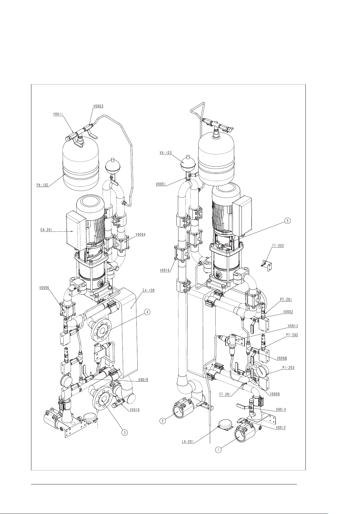
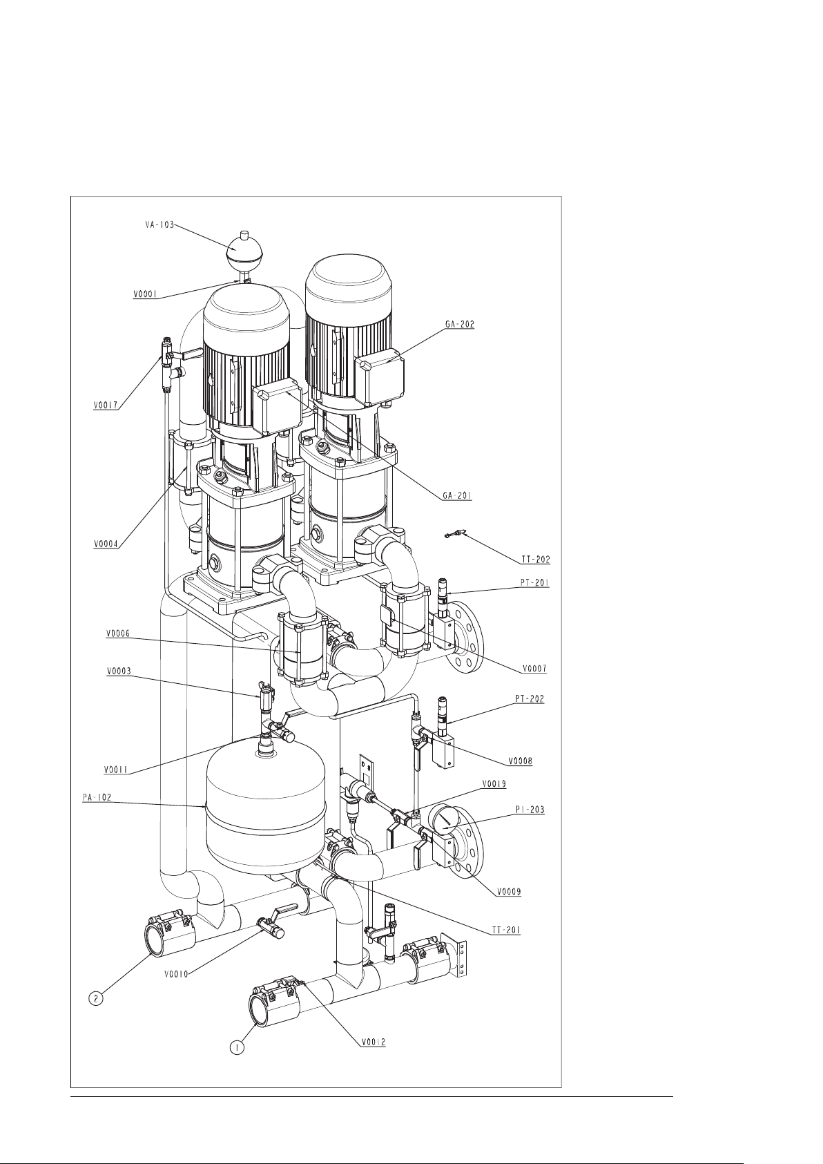
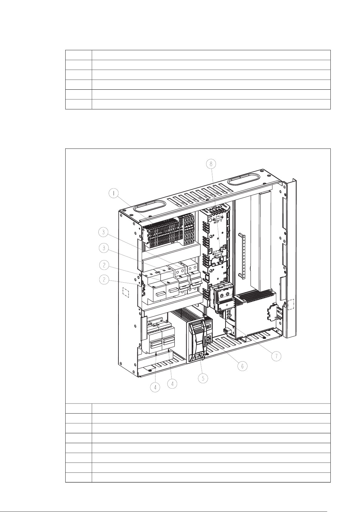
Layout drawing – ACS880-1007LC-0070 in cabinet line-up
This figure shows the interior of the cooling unit which is attached to the right end of the
drive cabinet line-up. The user connects the external cooling circuit from right.
Page 15

Operation basics and hardware description 15
■ ACS880-1007LC-0070 component designations
The table below lists the component designations used in layout drawings, piping and
instrumentation (PI) diagrams, and circuit diagrams.
Layout
drawing
-
V0004,
V0006
PI diagram
210
V0006
diagram
-TIA(C)-
DescriptionCircuit
Outlet to internal cooling circuit--1
Inlet from internal cooling circuit--2
Inlet from external cooling circuit--3
Outlet to external cooling circuit--4
Pump de-airing screw--5
Coolant pump 1-M201GA-201GA-201
Heat exchanger-EA-100EA-100
Expansion tank-PA-102PA-102
Automatic float air vent-VA-103VA-103
Pump inlet pressure transmitter with low limit alarm-T201PT-201PT-201
Pump outlet pressure transmitter-T202PT-202PT-202
Coolant pressure gauge-PT-203PT-203
Coolant temperature indicator and alarm (and control, if optional 2-way valve
installed). This device is the LCU control unit.
Coolant temperature transmitter-B201TT-201TT-201
Ambient temperature transmitter-B202TT-202TT-202
Cabinet temperature transmitter(-A210)TT-210-
Shut-off valve for automatic float air vent-V0001V0001
Pressure transmitter (PT-201) shut-off valve-V0002V0002
Pressure transmitter (PT-202) shut-off valve-V0008V0008
Pressure gauge (PI-203) shut-off valve-V0009V0009
Expansion tank shut-off valve-V0003V0003
Pump shut-off valves-V0004,
Drain/fill valve (internal circuit LCU inlet)-V0010V0010
Expansion tank bleed valve-V0011V0011
Drain valve (internal circuit LCU outlet)-V0012V0012
Fill valve (Internal circuit LCU outlet)-V0014V0014
Safety relief valve (UL option only)-V0013V0013
Flow control valve-V0016V0016
Flow control valve (Optional, if 2-way valve installed)-V0018V0018
Shut off valve for the Safety relief valve-V0019V0019
Strainer (Optional, if 2-way valve installed)-SA-104-
LCU Leakage detectorS201LA-201LA-201
VAU Leakage detectorS211LA-211-
Page 16
16 Operation basics and hardware description
Layout drawing – ACS880-1007LC-0195 in cabinet line-up
These figures show the interior of the cooling unit which is attached to the right end of the
drive cabinet line-up. The user connects the external cooling circuit from right. Page 1/2:
Page 17
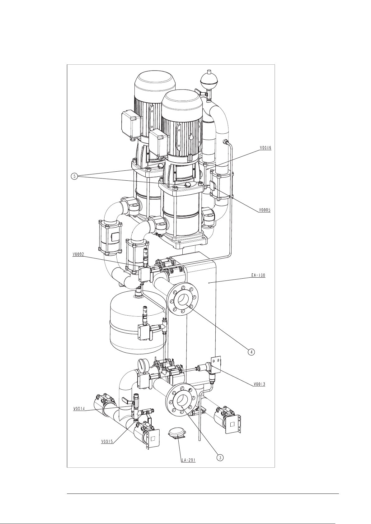
Page 2/2
Operation basics and hardware description 17
Page 18

18 Operation basics and hardware description
■ ACS880-1007LC-0195 component designations
The table below lists the component designations used in layout drawings, piping and
instrumentation (PI) diagrams, and circuit diagrams.
Layout
drawing
-
V0004,
V0005,
V0006,
V0007
PI diagram
210
V0005,
V0006,
V0007
diagram
-TIA(C)-
DescriptionCircuit
Outlet to internal cooling circuit--1
Inlet from internal cooling circuit--2
Inlet from external cooling circuit--3
Outlet to external cooling circuit--4
Pump de-airing screw--5
Coolant pump 1-M201GA-201GA-201
Coolant pump 2-M202GA-202GA-202
Heat Exchanger-EA-100EA-100
Expansion tank-PA-102PA-102
Automatic float air vent-VA-103VA-103
Pump inlet pressure transmitter with low limit alarm-T201PT-201PT-201
Pump outlet pressure transmitter-T202PT-202PT-202
Coolant pressure gauge-PT-203PT-203
Coolant temperature indicator and alarm (and control, if optional 2-way valve
installed)
Coolant temperature transmitter-B201TT-201TT-201
Ambient temperature transmitter-B202TT-202TT-202
Cabinet temperature transmitter(-A210)TT-210TT-210
Shut-off valve for automatic float air vent-V0001V0001
Pressure transmitters (PT-201) shut-off valve-V0002V0002
Pressure transmitter (PT-202) shut-off valve-V0008V0008
Pressure gauge (PI-203) shut-off valve-V0009V0009
Expansion tank shut-off valve-V0003V0003
Pump shut-off/check valves-V0004,
Drain/fill valve (internal circuit LCU inlet)-V0010V0010
Expansion tank bleed valve-V0011V0011
Drain/fill valve (internal circuit LCU outlet)-V0012V0012
Fill valve (internal circuit LCU outlet)-V0014V0014
Safety relief valve (UL option only)-V0013V0013
Flow control valve-V0016V0016
Shut off valve for extra LCU cubicle cooler (with option +C213 only)-V0015V0015
Shut off valve for extra LCU cubicle cooler (with option +C213 only)-V0017V0017
Flow control valve (Optional, if 2-way valve installed)-V0018V0018
Strainer (Optional, if 2-way valve installed)-SA-104-
Shut off valve for the Safety relief valve-V0019V0019
Leakage detectorS201LA-201LA-201
VAU Leakage detectorS211LA-211-
Page 19
Operation basics and hardware description 19
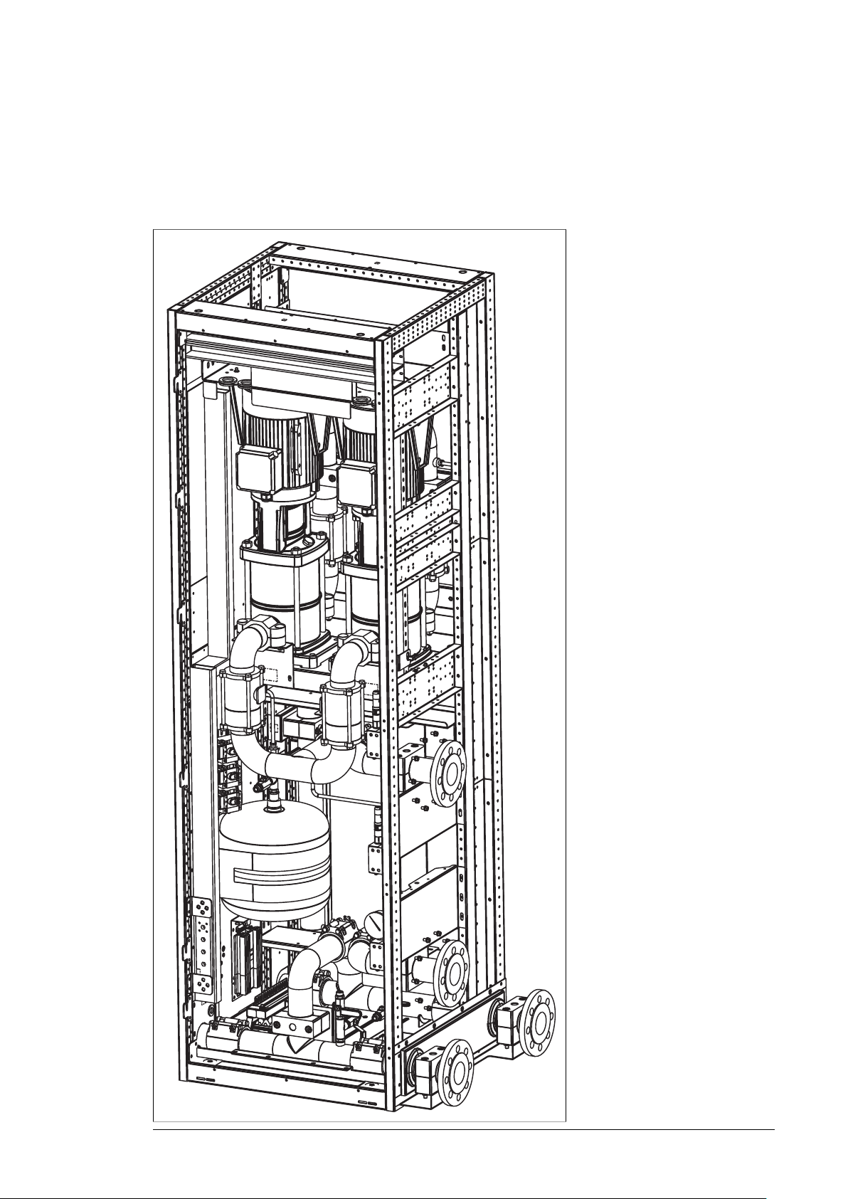
Layout drawing – ACS880-1007LC-0195 stand-alone (option +C139)
This figure shows a stand-alone cooling unit. The user connects both the internal and external
cooling circuits from right.
Page 20
20 Operation basics and hardware description
The components are described in section Layout drawing – ACS880-1007LC-0195 in cabinet
line-up (page 16).
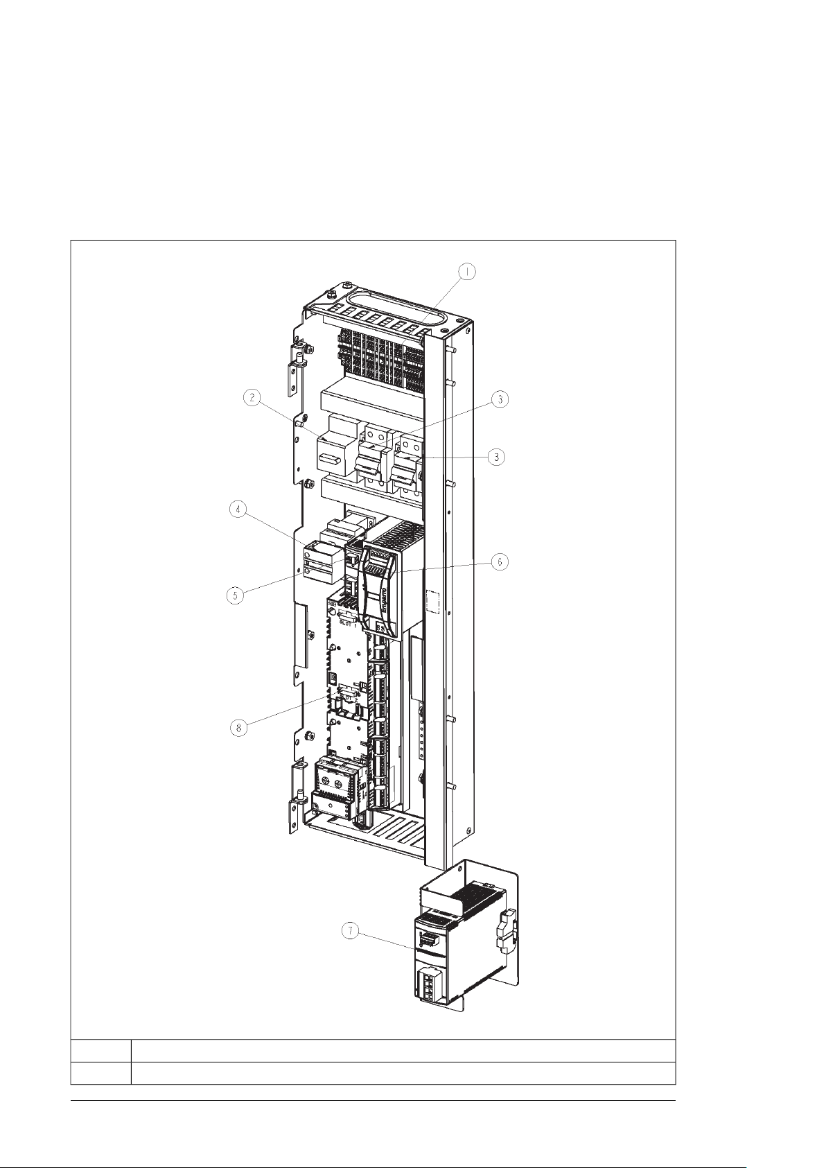
Swing out frame for electric devices in ACS880-1007LC-0070
Terminal block (X201)1.
Motor protective circuit breaker for pump (F201)2.
Page 21
Operation basics and hardware description 21
Circuit breakers for control voltage & cabinet heater (F210, F295)3.
Main contactor for pump (Q201)4.
Power supply for lighting (T130)5.
24 V DC power supply (for control board) (T210)6.
Buffer unit (C210)7.
ZCU control unit (A210)8.
Swing out frame for electric devices in ACS880-1007LC-0195
Terminal block (X201)1.
Motor protective circuit breaker for pump (F201, F202)2.
Circuit breakers for control voltage & cabinet heater (F210, F295)3.
Main contactor for pump (Q201, Q202)4.
24 V DC power supply (for control board) (T210)5.
Power supply for lighting (T130)6.
Buffer unit (C210)7.
ZCU control unit (A210)8.
Page 22

22 Operation basics and hardware description
Control interfaces
■ General
The control program runs on the ZCU-14 control unit. The IO interface of the control unit is:
• the standard interface for the internal control and status signals (pump status, pressure
monitoring, pump on/off, etc.)
• the default interface for the external control signals (start, reset, fault indication).
User cannot change the interface for the internal signals. For the external signals, user can
use these signal interfaces also instead of the IO interface:
• a control panel (optional), or a PC with the Drive composer PC tool (optional)
• a fieldbus adapter module (optional)
• A DDCS communication adapter (optional).
User selects the external control interface by the control panel and a parameter (20.03):
• When the control panel is on the local control mode, the control panel is the control
interface (despite of any parameter value).
• When the control panel is on the remote control mode, the parameter selection defines
the control interface in use.
You can switch between local and remote control modes by the Loc/Rem key of the control
panel.
■ Control panel
Typically, there is a dedicated control panel in the stand-alone unit, and when the unit is in
the multidrive cabinet line-up. When the unit is part of the single drive line-up, there is no
dedicated panel for the cooling unit but the drive panel can also communicate with the
cooling unit.
■ IO interface of the control unit
This table shows the signals of the control unit IO interface.
IO
tion
XDI.2DI2
DescriptionDesigna-
Status of the pump 1 motor protective circuit breaker (1 = ON)XDI.1DI1
Status of the pump 2 motor protective circuit breaker (1 = ON). Not in use in one-pump
cooling unit.
Leakage detector (1 = LEAKAGE)XDI.3DI3
Reset (1 = RESET)XDI.4DI4
Not in useXDI.5DI5
Start signal (1 = START)XDI.6DI6
Not in useXDIO.1DIO1
Not in useXDIO.1DIO2
Not in useXD24.1DIIL
Pump 1 control (1 = RUN)XRO1RO1
Pump 2 control (1 = RUN). Not in use in one-pump cooling unit.XRO2RO2
Page 23

Operation basics and hardware description 23
IO
tion
DescriptionDesigna-
Fault indication (0 = Fault)XRO3RO3
Inlet pressure sensorXAI.4-5AI1
Outlet pressure sensorXAI.6-7AI2
2-way control valve control (optional)XAO.1-2AO1
Not in useXAO.3-4AO2
Ambient temperature sensorX209
■ IO interface of the FAIO-01 analog interface module
This table shows the signals of the FAIO-01 analog interface module. The module is attached
on the control unit as standard.
IO
tion
DescriptionDesigna-
Coolant temperature signal from the sensor (0…2 V)XA1AI1
Not in useXAI2AI2
Current source for the coolant temperature measurement sensor (0…20 mA)XAO1AO1
Not in useXAO2AO2
■ Use of the control unit expansion slots
The control unit has three expansion slots. This table shows the possible use of the slots.
DescriptionSlot
Slot 1
Slot 2
Slot 3
FAIO-01 analog interface module (standard). Interface for the internal coolant temperature monitoring.
FENA-11 Ethernet adapter module (optional). You can connect a PC with drive PC tool via Ethernet
to FENA adapter and further to the cooling unit.
Fieldbus adapter module (optional), or FDCO-01 DDCS adapter module and FDPI-02 for panel
bus adapter (optional)
■ PC connection
There is a USB connector on the front of the control panel that can be used to connect a
PC to the drive. When a PC is connected to the control panel, the control panel keypad is
disabled.
If the cooling unit is equipped with an Ethernet adapter module FENA-11 or -21 (option
+K473 or +K475), you can connect the PC with an Ethernet cable.
Page 24
24 Operation basics and hardware description
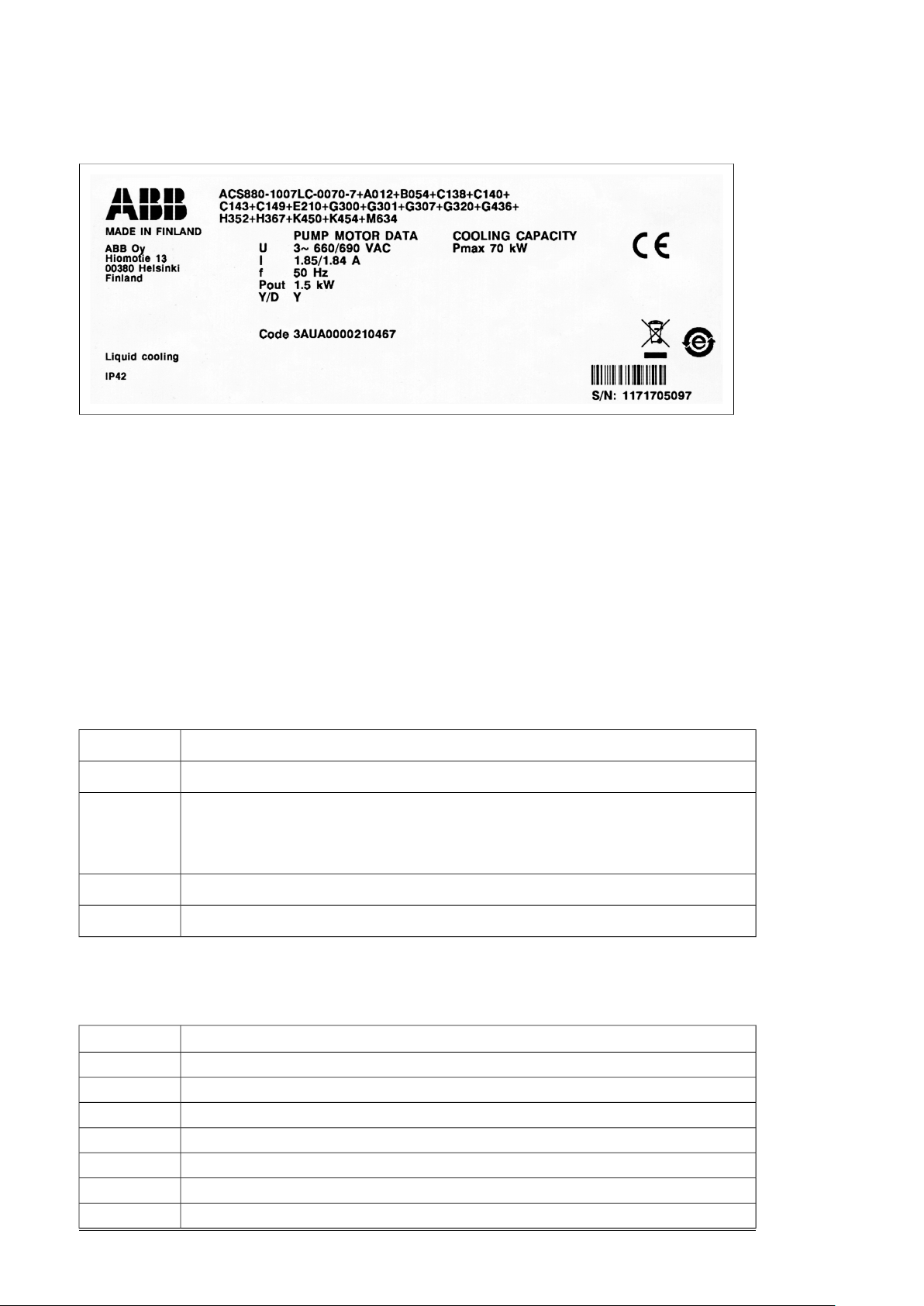
Type designation label
Type designation key
The type designation describes the composition of the module in short. The complete
designation code is divided in sub-codes:
• The first digits form the basic code. It describes the basic construction of the unit. The
fields in the basic code are separated by hyphens.
• The option codes (plus codes) follow the basic code. Each code starts with an identifying
letter (common for the whole product series), followed by descriptive digits. The plus
codes are separated by plus signs.
■ Basic code
The table below describes the fields of the basic code. ACS880-1007LC-0070-7 is used as
an example.
DescriptionFields
Product series. ACS880: Industrial drives.ACS880
1007LC
Unit identifier. 1007LC: Cooling unit. Standard features (if not defined otherwise by the option
codes): pipe connections from right, industrial water in external cooling circuit, 50 mm plinth
height, door hinges on right, standard cable entry plate, manuals on USB stick, coolant Antifrogen® L 25%.
Unit size. 0070: 0070 kW, 0195: 195 kW.0070
Voltage rating. 4: 380/400 V AC, 7: 660/690 V AC.7
■ Option codes
The table below describes the option codes (plus codes).
DescriptionCode
50 Hz supply frequencyA012
60 Hz supply frequencyA013
IP42, UL type 1B054
IP54, UL type 12B055
Marine constructionC121
UL-approvedC129
CSA-approvedC134
Page 25

Operation basics and hardware description 25
DescriptionCode
Line-up connected cooling unitC138
stand-alone cooling unitC139
Single pump cooling unitC140
Redundant pump cooling unitC141
Bottom pipe connectionC142
Pipe connection on leftC144
ANSI flangesC145
Sea waterC146
2-way valve in own cabinetC147
100 mmC164
200 mmC179
Door hinges on leftC176
Two pumps runningC213
100 kA short circuit ratingF274
Cabinet heaterG300
Cabinet lightingG301
115 VAC supply voltageG304
230 VAC supply voltageG320
External control voltage supplyG307
Halogen free wiringG330
Bottom power cable entryH352
Top power cable entryH353
Cable gland plates (Steel 3 mm, non-drilled)H358
Cable gland plates (Aluminum 3 mm, non-drilled)H364
Cable gland plates (Brass 6 mm, non-drilled)H365
Lead through, diameter 72 mmH390
Bottom control cable entryH367
Top control cable entryH368
Control panelJ400
Common control panelJ412
FDNA-01 fieldbus adapterK451
FLON-01 fieldbus adapterK452
FPBA-01 (PROFIBUS DP, DPV0/DPV1) fieldbus adapterK454
FCAN-01 fieldbus adapterK457
FSCA-01 fieldbus adapterK458
FCNA-01 fieldbus adapterK462
FECA-01 fieldbus adapterK469
FEPL-02 fieldbus adapterK470
FENA-11 (EtherNet/IP, Modbus/TCP, PROFINET) ethernet adapterK473
FENA-21 (EtherNet/IP, Modbus/TCP, PROFINET IO) Daisy chain ethernet adapterK475
Ethernet switch for PC tool and control networkK480
Ethernet switch with optical link for PC tool and control networkK483
Page 26

26 Operation basics and hardware description
DescriptionCode
Ethernet switch for PROFINETK493
Ethernet switch with optical link for PROFINETK494
FDCO-02, DDCS Communication 5/10 MBdL508
RDCO-04, DDCS CommunicationL509
Additional I/O terminal blockL504
Motor in delta connectionM633
Motor in star connectionM634
Special colorP913
Manuals in EnglishR700
R701
R702
R705
R706
R707
R708
R711
R712
R717
Manuals in German
Manuals in Italian
Manuals in Swedish
Manuals in Finnish
Manuals in French
Manuals in Spanish
Manuals in Russian
Manuals in Chinese
User´s manuals paper copy, one setR716
Paper copy of user's manual in A4, paper copy of dimensional drawings and circuit diagrams
in A3
1)
1)
1)
1)
1)
1)
1)
1)
1)
Some manuals are only available in English.
Page 27
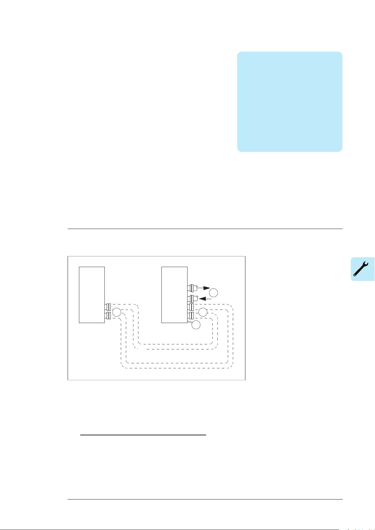
Mechanical installation
Drive
2
LCU
4
3 3
Mechanical installation 27
3
The figure below shows the internal and external cooling circuit connections of the
stand-alone cooling unit (option +C139).
Procedure:
1. Fasten the cooling unit to the floor. See the appropriate drive manual for the instructions.
In marine installation (or other cases where the unit will be subjected to vibration), fasten
the unit also from above.
2. Lead the bottom leakage hose to a sewer.
3. Stand-alone cooling unit (option +C139): Connect the drive internal cooling circuit to
the cooling unit. Use only the bolt and nut types, and tightening torque specified in
section Flanges for connecting the piping (page 111). Secure the pipes mechanically.
4. Connect the external cooling circuit to the cooling unit. Use only the bolt and nut types,
and tightening torque specified in section Flanges for connecting the piping (page 111).
Secure the pipes mechanically.
Page 28

28
Page 29
Electrical installation
Electrical installation 29
4
What this chapter contains
This chapter shows the user connections of the liquid cooling unit (LCU).
Safety
WARNING!
Read and obey the complete safety instruction of the drive. If you ignore them,
injury or death, or damage to the equipment can occur. Only a qualified electrician
may do the work described in this chapter.
■ Electrical safety precautions
These electrical safety precautions are for all personnel who do work on the drive, motor
cable or motor.
WARNING!
Obey these instructions. If you ignore them, injury or death, or damage to the
equipment can occur. If you are not a qualified electrician, do not do installation
or maintenance work. Go through these steps before you begin any installation or
maintenance work.
1. Keep the cabinet doors closed when the drive is powered. With the doors open, a risk
of a potentially fatal electric shock, arc flash or high-energy arc blast exists.
2. Clearly identify the work location.
3. Disconnect all possible voltage sources.
• Open the main disconnecting device of the drive.
• Open the charging switch if present.
Page 30
30 Electrical installation
• Open the auxiliary voltage switch-disconnector (if present), and all other possible
disconnecting devices that isolate the drive from dangerous voltage sources.
• In the liquid cooling unit (if present), open the motor protective circuit breaker(s) of
the cooling pumps.
• If you have a permanent magnet motor connected to the drive, disconnect the motor
from the drive with a safety switch or by other means.
• Make sure that re-connection is not possible. Lock the disconnectors to open position
and attach a warning notice to them.
• Disconnect any external power sources from the control circuits before you do work
on the control cables.
• After you disconnect the drive, always wait 5 minutes to let the intermediate circuit
capacitors discharge before you continue.
4. Protect any other energized parts in the work location against contact.
5. Take special precautions when close to bare conductors.
6. Measure that the installation is de-energized. If the measurement requires removal or
disassembly of shrouding or other cabinet structures, obey the local laws and regulations
applicable to live working (including – but not limited to – electric shock and arc
protection).
• Use a multimeter with an impedance of at least 1 Mohm.
• Make sure that the voltage between the drive input power terminals and the
grounding (PE) busbar is close to 0 V.
• Make sure that the voltage between the drive DC busbars (+ and -) and the
grounding (PE) busbar is close to 0 V.
7. Install temporary grounding as required by the local regulations.
8. Ask the person in control of the electrical installation work for a permit to work.
Connecting the power cables
WARNING!
Read and obey the complete safety instruction of the drive. If you ignore them,
injury or death, or damage to the equipment can occur. Only a qualified electrician
may do the work described in this chapter.
WARNING!
Do the steps in section Electrical safety precautions (page 29) before you start
the work on drive and cooling unit. Go through the checklist together with another
person.
Page 31

M
3~
L1
1~
2)
LN
L2 L3
3~
1)
ACS880-1007LC
PE
Q200
246
123
PE
4) 4)
Q210
246
123
1~ 3)
LN
4)
Q295
246
123
Electrical installation 31
■ Connection diagram – pump motors, auxiliary circuit and cubicle
heater
1
Three-phase power supply for the pump motor(s). User connects on site to a user-defined power supply.
Voltage, power rating and fuses: See the type designation label, chapter Technical data (page 109) and
the delivery-specific circuit diagrams.
One-phase auxiliary power supply for the control circuit.
2
Cooling unit in drive cabinet line-up: Connected to the drive auxiliary voltage supply at the factory. No
user connection on site needed. See the delivery-specific circuit diagrams.
Stand-alone cooling unit: User connects on site to a user-defined power supply. Voltage, power rating
and fuses: See the type designation label, chapter Technical data (page 109) and the delivery-specific
circuit diagrams.
One-phase auxiliary power supply for the cabinet heater (option +G300).
3
Cooling unit in drive cabinet line-up: Connected to the drive auxiliary voltage supply at the factory. No
user connection on site needed. See the delivery-specific circuit diagrams.
Stand-alone cooling unit: User connects on site to a user-defined power supply. Voltage, power rating
and fuses: See the type designation label, chapter Technical data (page 109) and the delivery-specific
circuit diagrams.
See the delivery-specific circuit diagrams.4
Connecting the control cables
WARNING!
Read and obey the complete safety instruction of the drive. If you ignore them,
injury or death, or damage to the equipment can occur. Only a qualified electrician
may do the work described in this chapter.
WARNING!
Do the steps in section Electrical safety precautions (page 29) before you start
the work on drive and cooling unit. Go through the checklist together with another
person.
Page 32

32 Electrical installation
Cooling unit in drive cabinet line-up (option +C138): As standard, there are no control
connections to be connected by the user. The supply unit of the drive controls the LCU, and
the connections are done at the factory. See the delivery-specific circuit diagrams.
Stand-alone cooling unit (option +C139): Connect the external control cabling according to
the delivery-specific circuit diagrams.
■ Control cable connection procedure
1.
Stop the drive (if running) and do the steps in section Electrical safety
precautions (page 29) before you start the work.
2.
Run the control cables into the cabinet as described in section Grounding the outer
shields of the control cables at the cabinet entry below.
3.
Route the control cables as described in section Routing the control cables inside the
cabinet (page 34).
4.
Connect the control cables as described in section Connecting control cabling (page 34).
Grounding the outer shields of the control cables at the cabinet entry
Ground the outer shields of all control cables 360 degrees at the EMI conductive cushions
as follows (example constructions are shown below, the actual hardware may vary):
1. Loosen the tightening screws of the EMI conductive cushions and pull the cushions
apart.
2. Cut adequate holes to the rubber grommets in the entry plate and put the cables through
the grommets and the cushions.
3. Strip off the cable plastic sheath above the entry plate just enough to ensure proper
connection of the bare shield and the EMI conductive cushions.
4. Tighten the two tightening screws so that the EMI conductive cushions press tightly
round the bare shield.
Page 33

2
1
4
1
4
3
2
4
1
4
1
3
grounding wire (if present).
uous.
A Stripped cable
B Conductive surface of the shield exposed
C Stripped part covered with copper foil
1 Cable shield
2 Copper foil
3 Shielded twisted pair
4 Grounding wire
1
A B C
2 2
3
4
Electrical installation 33
Note 1: Keep the shields continuous as close to the connection terminals as possible.
Secure the cables mechanically at the entry strain relief.
Note 2: If the outer surface of the shield is non-conductive:
• Cut the shield at the midpoint of the bare part. Be careful not to cut the conductors or
the grounding wire (if present).
• Turn the shield inside out to expose its conductive surface.
• Cover the turned shield and the stripped cable with copper foil to keep the shielding
continuous.
Stripped cableA
Conductive surface of the shield exposedB
Stripped part covered with copper foilC
Cable shield1
Copper foil2
Shielded twisted pair3
Grounding wire4
Page 34

Electrical installation 99
co
nductive cushions.
34 Electrical installation
Note for top entry of cables: When each cable has its own rubber grommet, sufficient IP
and EMC protection can be achieved. However, if very many control cables come to one
cabinet, plan the installation beforehand as follows:
1. Make a list of the cables coming to the cabinet.
2. Sort the cables going to the left into one group and the cables going to the right into
another group to avoid unnecessary crossing of cables inside the cabinet.
3. Sort the cables in each group according to size.
4. Group the cables for each grommet as follows ensuring that each cable has a proper
contact to the cushions on both sides.
Max. number of cables per grommetCable diameter in mm
4≤ 13
3≤ 17
2< 25
1≥ 25
5. Arrange the bunches according to size from thickest to the thinnest between the EMI
conductive cushions.
6. If more than one cable go through a grommet, seal the grommet by applying Loctite
5221 (catalogue number 25551) inside the grommet.
Routing the control cables inside the cabinet
Use the existing trunking in the cabinet wherever possible. Use sleeving if cables are laid
against sharp edges. When running cables to or from a swing-out frame, leave enough
slack at the hinge to allow the frame to open fully.
Connecting control cabling
Connect the conductors to the appropriate terminals. Refer to the wiring diagrams delivered
with the drive.
Connect the inner twisted pair shields and all separate grounding wires to the grounding
clamps closest to the terminals.
The drawing below represents the grounding of the control cabling when connecting to a
terminal block inside the cabinet. The grounding is done in the same way when connecting
directly to a component such as the control unit.
Notes:
• Do not ground the outer shield of the cable here since it is grounded at the lead-through.
• Keep any signal wire pairs twisted as close to the terminals as possible. Twisting the
wire with its return wire reduces disturbances caused by inductive coupling.
Page 35

100 Electrical installation
Electrical installation 35
At the other end of the cable, leave the shields unconnected or ground them indirectly via
a high-frequency capacitor with a few nanofarads, eg. 3.3 nF / 630 V. The shield can also
be grounded directly at both ends if they are in the same ground line with no significant
voltage drop between the end points.
Page 36

36
Page 37

Installation checklist
Installation checklist 37
5
Check the installation before start-up. Go through the checklist together with another person.
WARNING!
Read and obey the complete safety instruction of the drive. If you ignore them,
injury or death, or damage to the equipment can occur. Only a qualified electrician
may do the work described in this chapter.
WARNING!
Do the steps in section Electrical safety precautions (page 29) before you start
the work on drive and cooling unit. Go through the checklist together with another
person.
Task
The drive installation has been checked against the checklists in the drive manuals.
The cooling unit has been fixed properly to floor. In marine applications the unit has also been fastened
from above.
The bottom leakage hose has been led to a sewer.
The power supply voltage for the pump motor(s) matches the motor nominal voltage.
The power supply cable for the pump motor(s) has been connected to appropriate terminals and the
connection is tight. Pull conductors to check.
The PE (ground) conductor has been connected and the connection is tight. Pull conductor(s) to check.
Stand-alone cooling unit (option +C139): Auxiliary power supply for the control circuit has been connected
to appropriate terminals and the connection is tight. Pull conductors to check.
Stand-alone cooling unit with cabinet heater (option +G300): The power supply for the cabinet heater
has been connected to appropriate terminals and the connection is tight. Pull conductors to check.
The external control cabling (if any) has been connected to appropriate terminals and the connections
are tight. Pull conductors to check.
There are no tools, foreign objects or dust from drilling inside the cooling unit.
Page 38

38 Installation checklist
Task
All bleed valves and drain valves are closed (drive and cooling unit).
The external cooling circuit is connected and the connections are tight.
Stand-alone cooling unit (option +C139): The internal cooling circuit is connected and the connections
are tight.
Page 39
Start-up
Start-up 39
6
Contents of this chapter
This chapter contains a list for checking the installation.
Safety
WARNING!
Read and obey the complete safety instruction of the drive. If you ignore them,
injury or death, or damage to the equipment can occur. Only a qualified electrician
may do the work described in this chapter.
Before start-up
Task
Use the required personal protective equipment. See the Safety data sheet for Antifrogen® L coolant by
Clariant (www.clariant.com) for the instructions on the respiratory, hand and eye protection.
Make sure that you have enough of right type of coolant at hand. For the coolant type, see Technical
data (page 105). For the quantity of coolant in the drive cooling circuit: See the appropriate hardware
manual(s). Quantity in the cooling unit: See Technical data.
Check that the coolant temperature and the ambient temperature are within the limits. See Technical
data (page 105), and Ambient conditions (page 111).
Page 40

40 Start-up
Task
Check that you have at hand:
• tools
• air pump with a pressure gauge and standard tyre head for the air pressure adjustment of the expansion
tank
• container filled with coolant
• buckets for bleeding and draining of the system
• hoses for filling, draining and bleeding. Three hoses are included as standard in the cooling unit delivery.
See also Fill/drain/bleed hoses (page 110).
• pump for filling the coolant. We recommend a hand pump with max. 5 l/min capacity for slow and airfree fill up. See also Filling pump (page 110).
If the cooling unit has been stored in cold or damp environment, warm and dry it with the cabinet heater
or by some other means before the start.
Adjusting air pressure of the expansion tank
■ About the expansion tank
The expansion tank is divided into two sections: liquid and air section. The air section is the
reservoir into which the liquid section expands whenever a temperature rise increase the
volume of the liquid in the system. You must set the air counterpressure at the system
start-up.
■ Pressure adjusting procedure
The component designations refer to Piping and instrumentation diagrams (page 115) and
Operation basics and hardware description (page 13). Study the drawings before starting
the task and keep them at hand when performing it.
WARNING!
Do the steps in Electrical safety precautions (page 29) before you start the work
on drive and cooling unit. Go through the checklist together with another person.
WARNING!
Read and obey the safety instructions of the liquid cooling system. See the complete
safety instructions of the drive. If you ignore them, injury or death, or damage to
the equipment can occur.
Use the required personal protective equipment. See the Safety data sheet for
Antifrogen® L coolant by Clariant (www.clariant.com) for the instructions on the
respiratory, hand and eye protection.
Avoid skin contact with coolant. If liquid splashes into skin or eyes, rinse
immediately with plenty of water.
Task
Close the shut-off valve (V003) through which the expansion tank (PA-102) is coupled to the internal
cooling circuit.
Connect a hose to the bleed valve (V011) of the expansion tank and lead the hose to a bucket.
Open bleed valve to release pressure - if any - of the upper (liquid) section of the expansion tank.
Remove (unscrew by hand) the protective cap that covers the air valve at the bottom of the expansion
tank.
Page 41
Start-up 41
Task
Connect an air pump with a gauge to the air valve and measure the pressure in the lower section of the
expansion tank. Control the pressure to 40 kPa. Replace the cap onto the air valve.
Close the bleed valve (V011) and remove the hose from the valve.
Open the shut-off valve (V003).
Filling up the cooling circuit and starting the cooling unit
WARNING!
Do the steps in Electrical safety precautions (page 29) before you start the work
on drive and cooling unit. Go through the checklist together with another person.
WARNING!
Read and obey the safety instructions of the liquid cooling system. See the complete
safety instructions of the drive. If you ignore them, injury or death, or damage to
the equipment can occur.
Use the required personal protective equipment. See the Safety data sheet for
Antifrogen® L coolant by Clariant (www.clariant.com) for the instructions on the
respiratory, hand and eye protection.
Avoid skin contact with coolant. If liquid splashes into skin or eyes, rinse
immediately with plenty of water.
Keep the pump shutt-off valves closed until you start filling the internal cooling circuit. The
pumps are filled with a protective mixture at the factory. The mixture can be left in the cooling
circuit.
The component designations refer to the drawings in Piping and instrumentation
diagrams (page 115) and Operation basics and hardware description (page 13). Study the
drawings before starting the task and keep them at hand when performing it.
Task
Preparing the drive and cooling unit
Check and adjust the air pressure in the expansion tank if not done yet. See Adjusting air pressure of the
expansion tank (page 40).
Check that the drain valves in all cubicles of the drive cabinet line-up are closed.
Open the valves at the inlet and outlet of the pump(s) (V0004, V0006, V00051), V00071), GA-101, GA-
1021)).
Open inlet, outlet and bleed valves in one cubicle of the drive. Keep the valves still closed in the other
drive cubicles. (The cubicles will be filled one at a time.)
Connect a filling hose to the fill valve of the cooling unit (V0012 or V00141)).
Lead the bleed hose of the drive cubicle to bucket.
Open the shut-off valve (V0001) of the automatic float air vent (VA-103).
Open the fill valve of the cooling unit (V0012 or V00141)).
Filling
Fill the system by pumping coolant in through the fill valve (V0012 or V00141)). Pump slowly to keep air
out.
Page 42

42 Start-up
Task
When there is sufficient amount of coolant in the piping, coolant begins to overflow from the bleed hose
of the drive cubicle. Drain some coolant to get all air out of the system, then close the bleed, inlet and
outlet valves in the drive cubicle.
Lead the bleed hose of the next drive cubicle to a bucket, and open the inlet, outlet and bleed valves of
the cubicle. Fill and bleed the drive cubicle. Repeat the procedure for the remaining drive cubicles.
Open the inlet and outlet valves of all drive cubicles and let the remaining air come out through the
automatic float air vent (VA-103) of the cooling unit. The pressure in the internal circuit starts to rise.
Monitor the pressure on the pressure gauge (PT-203). Increase the pressure up to 100…150 kPa by
pumping coolant in from the fill valve (V0012 or V00141)). When the pressure has been reached, close
the fill valve and stop the fill-in pump. Keep the fill hose still coupled for later use.
Open the pump bleed valves somewhat and let the air out. Check the pressure again, and add some
coolant if necessary.
WARNING!
Do not fill in too much coolant. Ensure that the maximum permissible operating pressure (600 kPa,
indicated by pressure gauge PT-203) is not exceeded.
Starting the cooling unit and checking the pressure
Connect power to the cooling unit.
Close the door of the cooling unit.
Start the pump for one or two minutes.
• With the control panel: Switch the control panel to the Local control mode (Loc/Rem key). Start the
pump with the Start key of the panel.
• External control device: The remote start options depend on the control location selection. See parameter 20.03 and the delivery specific circuit diagrams.
Ensure that the flow control valve (V0016) is set to the design position which is shown on the label beside
the valve.
Monitor inlet and outlet liquid pressures of the pump (01.01, 01.02) on the control panel (Inside the cooling
unit, there is also pressure gauge PT-203).
Stop the pump by pressing the Stop key of the control panel: The pressure gauge should indicate pressure
100... 150 kPa when the pump is stopped.
Re-start the pump for couple of minutes.
Listen for a humming sound or feel the piping for vibration to find out if there is still air left. If these
symptoms appear:
• Make sure that the shut-off valve for automatic float air vent (VA-103) is open.
• Stop the pump, open the pump bleed valves and let air out. If necessary, add coolant (until pressure
of 150 kPa is reached). Repeat the procedure until all air is removed from the system.
Stop the pump. Check that all drain and bleed valves are closed. Remove the filling hose.
1)
Only in the two-pump cooling unit.
Basic settings in the control program
For more information on the use of the control panel, see ACX-AP-x Assistant control panels
user's manual (3AUA0000085685 (English)).
Task
Check that the number of pumps setting corresponds to actual number of pumps (20.04).
Two-pump unit ACS880-1007LC-0195: Activate and tune the delays of the automatic pump alternation
function (20.01, 20.05, 20.06).
If the drive and the cooling unit will be out of use for long time periods, activate the Standby function
(20.08).
Page 43

Start-up 43
Task
Start/stop settings when the LCU will be controlled through the IO
Make sure that:
•
Parameter 20.03 = Local. (That is: The control interface selection defines a digital input DI6 as the
source for the start/stop signal in the remote control mode.)
• Control panel, if any, is in Remote control mode. Change with the Loc/Rem key when necessary.
Give start-command (and stop) command via digital input DI6. Verify that the cooling unit starts and stops
accordingly.
Start/stop settings when the LCU will be controlled through a serial link
Make sure that:
- Parameter 20.03 = Fieldbus A. (That is: The control interface selection defines fieldbus adapter A as
the source for the start/stop signal in the remote control mode.)
- Control panel, if any, is in Remote control mode. Change with the Loc/Rem key when necessary.
Give start-command and stop command from the overriding control system via Main control word bit b0.
Verify that the cooling unit starts and stops accordingly. You can monitor the command status from the
bits of parameter 06.01.
On-load settings
Task
Define the warning limit for the minimum pump inlet pressure (31.01). Set the warning limit 20 kPa below
the pressure value during normal operation. Parameter 01.01 shows the measured actual value.
Define the warning limit for the maximum coolant temperature at internal circuit outlet (31.10). If the
measured temperature during normal operation is below +36°C, decrease the default warning limit accordingly. Parameter 01.23 shows the measured actual value.
Define the warning limit for the maximum coolant pressure at the pump outlet with parameter 31.03. A
rule of thumb value: 50 kPa above the value measured during normal operation. Parameter 01.02 shows
the measured actual value.
Note: The higher the liquid temperature the higher the pressure.
Check the coolant temperature in the internal circuit as the load varies. Adjust/control the external cooling
circuit flow when necessary.
Page 44

44
Page 45

Maintenance
Maintenance 45
7
Safety
WARNING!
Read and obey the complete safety instruction of the drive. If you ignore them,
injury or death, or damage to the equipment can occur. Only a qualified electrician
may do the work described in this chapter.
Maintenance intervals
The tables below show the maintenance tasks which can be done by the end user. The
complete maintenance schedule is available on the Internet (www.abb.com/drivesservices).
For more information, consult your local ABB Service representative
www.abb.com/searchchannels).
Maintenance tasks, every year:
Tasks
Spare parts
ISpare parts
Inspections by user
ITightness of terminals
IDustiness, corrosion and temperature
ICooling liquid pipe connections
PCoolant antifreeze concentration
Page 46

46 Maintenance
Maintenance tasks, every 2nd year:
Maintenance tasks, every 3 to 9 years:
Coolant
Coolant pump
Aging
(Real-time clock)
clock)
Tasks
PInspection of coolant quality
Tasks and intervals (years from start-up)
21181512963
RRRCoolant draining and refill
RRRPump
RRRPump motor
RRRExpansion tank
RRRZCU/BCU control unit battery
RRControl panel battery (Real-time
Legend:
Inspection (visual inspection and maintenance action if needed)I
Performance of on/off-site work (commissioning, tests, measurements or other work)P
ReplacementR
Note:
• Maintenance and component replacement intervals are based on the assumption that
the equipment is operated within the specified ratings and ambient conditions. ABB
recommends annual drive inspections to ensure the highest reliability and optimum
performance.
• Long term operation near the specified maximum ratings or ambient conditions may
require shorter maintenance intervals for certain components. Consult your local ABB
Service representative for additional maintenance recommendations.
Adding cooling liquid
See Filling up the cooling circuit and starting the cooling unit (page 41).
Draining the cooling unit
The designations refer to the drawings in Piping and instrumentation diagrams (page 115).
Study the drawings before starting the task and keep them at hand when performing it.
WARNING!
Do the steps in Electrical safety precautions (page 29) before you start the work
on drive and cooling unit. Go through the checklist together with another person.
Page 47

Maintenance 47
WARNING!
Read and obey the safety instructions of the liquid cooling system. See the complete
safety instructions of the drive. If you ignore them, injury or death, or damage to
the equipment can occur.
Use the required personal protective equipment. See the Safety data sheet for
Antifrogen® L coolant by Clariant (www.clariant.com) for the instructions on the
respiratory, hand and eye protection.
Avoid skin contact with coolant. If liquid splashes into skin or eyes, rinse
immediately with plenty of water.
1. Stop the cooling unit and disconnect it from power line. Make sure by measuring that
the unit is de-energized.
2. Connect hoses to the drain/fill valves (V0010, V0012) and lead them into to a bucket.
3. Open the inlet and outlet valves of all drive cubicles, and make sure that the pump
shut-off valves (V004, V005, V0006, V007) are open.
4. Open the drain/fill valves (V0010, V0012) and let the liquid flow out of the system.
5. Open the expansion tank bleed valve (V0011) to let air displace the liquid.
6. Dry the piping with compressed oil free air if the system will be empty for long period.
Pressure may not exceed 600 kPa.
Storing the cooling unit
Fill the cooling circuit with coolant before the storing. See the procedure in Filling up the
cooling circuit and starting the cooling unit (page 41).
Checking the quality of the coolant
The manufacturer checks the quality of coolant free of charge. Send a 250 milliliter sample
to Clariant. See www.clariant.com.
Antifreeze on-site testers are available from the Antifrogen® Distributors. See
www.clariant.com.
Cleaning and drying the leakage detector
WARNING!
Do the steps in Electrical safety precautions (page 29) before you start the work
on drive and cooling unit. Go through the checklist together with another person.
WARNING!
Read and obey the safety instructions of the liquid cooling system. See the complete
safety instructions of the drive. If you ignore them, injury or death, or damage to
the equipment can occur.
Use the required personal protective equipment. See the Safety data sheet for
Antifrogen® L coolant by Clariant (www.clariant.com) for the instructions on the
respiratory, hand and eye protection.
Page 48

4
a
48 Maintenance
Avoid skin contact with coolant. If liquid splashes into skin or eyes, rinse
immediately with plenty of water.
1. Stop the cooling unit and disconnect it from power line.
2. Open the cabinet door. Make sure by measuring that the unit is de-energized.
3. If there is liquid on the bottom of the cooling unit, dry it. Dry also the leakage detector.
4. Release the fastening screw (a) of the detector assembly plate and pull the plate and
the detector out of the cabinet. The wiring cannot be disconnected but there is enough
slack in the wiring to do the cleaning
5. Rinse the detector with pure water and wipe the sensor dry carefully.
6. Re-install the detector.
7. Close the cabinet door, and energize the cooling unit. Reset the fault/warning.
8. If the fault/warning is repeated after the reset, the detector is faulty. Replace it.
ACS880-1007LC-0070 replacing the pump motor
WARNING!
Do the steps in Electrical safety precautions (page 29) before you start the work
on drive and cooling unit. Go through the checklist together with another person.
WARNING!
Read and obey the safety instructions of the liquid cooling system. See the complete
safety instructions of the drive. If you ignore them, injury or death, or damage to
the equipment can occur.
Use the required personal protective equipment. See the Safety data sheet for
Antifrogen® L coolant by Clariant (www.clariant.com) for the instructions on the
respiratory, hand and eye protection.
Avoid skin contact with coolant. If liquid splashes into skin or eyes, rinse
immediately with plenty of water.
1. Stop the cooling unit and disconnect it from power line.
2. Open the cabinet door. Make sure by measuring that the unit is de-energized.
3. Open the swing out frame on front of the pump:
• Remove the screws (a) that fasten the frame to the side of the cabinet frame.
• Remove the hinge locking screws (b) on top (1 pcs) and bottom (1 pcs) of the frame,
and turn the frame fully aside.
Page 49

64a5
b
c
3
b
a
Maintenance 49
4. Close the pump shut-off valves (c).
5. Open the motor connection box (a), disconnect the supply cable and pull it out of the
box. Turn the cables out of the way.
6. Remove the plate (b) on top of the pump motor (9 screws).
7. Remove the coupling guard (a) that covers the motor shaft (4 screws), and decouple
the motor and pump shafts.
8. Attach a lifting device to the pump motor to make sure that it is safe to remove the pump
fastening bolts.
9. Remove the bolts (a) that fasten the motor to the frame of the pump.
10. Lift the motor somewhat. Keep constant tension on the lifting rope. Pull the pump carefully
out of the cabinet.
11. Install a new motor.
Page 50

9
a
7
a
10
50 Maintenance
Page 51

Maintenance 51
ACS880-1007LC-0070 replacing the pump
WARNING!
Do the steps in Electrical safety precautions (page 29) before you start the work
on drive and cooling unit. Go through the checklist together with another person.
WARNING!
Read and obey the safety instructions of the liquid cooling system. See the complete
safety instructions of the drive. If you ignore them, injury or death, or damage to
the equipment can occur.
Use the required personal protective equipment. See the Safety data sheet for
Antifrogen® L coolant by Clariant (www.clariant.com) for the instructions on the
respiratory, hand and eye protection.
Avoid skin contact with coolant. If liquid splashes into skin or eyes, rinse
immediately with plenty of water.
1.
Do the steps in ACS880-1007LC-0070 replacing the pump motor (page 48).
2. Attach a lifting device to the pump to make sure that it is safe to remove its fastening
bolts.
3. Remove the inlet and outlet pipe couplings, and the pump fastening bolts:
• Remove the upper bracket (a) on front of the pump.
• Remove the lower bracket and its support plate (b) on front of the pump.
• Remove the upper bracket (c) on back of the pump.
• Remove the pump fastening bolts (d).
4. Move the pump sidewards.
5. Lift the pump upwards.
6. Pull the pump out of the cabinet.
7. Install a new pump.
Page 52

4
3
b
a
c
d
6
5
52 Maintenance
Page 53

Maintenance 53
ACS880-1007LC-0195 replacing the pump motor
WARNING!
Do the steps in Electrical safety precautions (page 29) before you start the work
on drive and cooling unit. Go through the checklist together with another person.
WARNING!
Read and obey the safety instructions of the liquid cooling system. See the complete
safety instructions of the drive. If you ignore them, injury or death, or damage to
the equipment can occur.
Use the required personal protective equipment. See the Safety data sheet for
Antifrogen® L coolant by Clariant (www.clariant.com) for the instructions on the
respiratory, hand and eye protection.
Avoid skin contact with coolant. If liquid splashes into skin or eyes, rinse
immediately with plenty of water.
1. Stop the cooling unit and disconnect it from power line.
2. Open the cabinet door. Make sure by measuring that the unit is de-energized.
3. Open the swing out frame on front of the pump:
• Remove the screws (a) that fasten the frame to the side of the cabinet frame.
• Remove the hinge locking screws (b) on top (1 pcs) and bottom (1 pcs) of the frame,
and turn the frame fully aside.
4. Close the pump inlet and outlet shut-off valves.
5. Open the motor connection box (a), disconnect the supply cable and pull it out of the
box. Turn the cables out of the way.
6. Remove the screws (11 pcs.) that fasten the plate on top of pump to the cabinet frame.
(You need to lift the plate later somewhat to get the pump out.)
7. Remove the coupling guard (a) that covers the motor shaft (4 screws), and decouple
the motor and pump shafts.
8. Remove the bolts (b) that fasten the motor to the frame of the pump.
9. Attach a lifting device to the pump to make sure that it is safe to remove its fastening
bolts.
10. Remove the screws (a, 2 pcs) that fasten the motor to supports on each side of the
pump.
11. Turn the motor somewhat, and at the same time lift the plate on top. Keep constant
tension on the lifting rope. Pull the motor carefully out of the cabinet.
12. Install a new motor.
Page 54

3
a
b
7a8
b
6
a
5
a
54 Maintenance
Page 55

11
10
a
Maintenance 55
ACS880-1007LC-0195 replacing the pump
WARNING!
Do the steps in Electrical safety precautions (page 29) before you start the work
on drive and cooling unit. Go through the checklist together with another person.
WARNING!
Read and obey the safety instructions of the liquid cooling system. See the complete
safety instructions of the drive. If you ignore them, injury or death, or damage to
the equipment can occur.
Use the required personal protective equipment. See the Safety data sheet for
Antifrogen® L coolant by Clariant (www.clariant.com) for the instructions on the
respiratory, hand and eye protection.
Avoid skin contact with coolant. If liquid splashes into skin or eyes, rinse
immediately with plenty of water.
1.
Do the steps in ACS880-1007LC-0195 replacing the pump motor (page 53).
2. Attach a lifting device to the pump to make sure that it is safe to remove its fastening
bolts.
3. Remove the inlet and outlet pipe couplings (a), and the pump fastening bolts (b).
4. Lift the pump upwards.
5. Pull the pump out of the cabinet.
Page 56
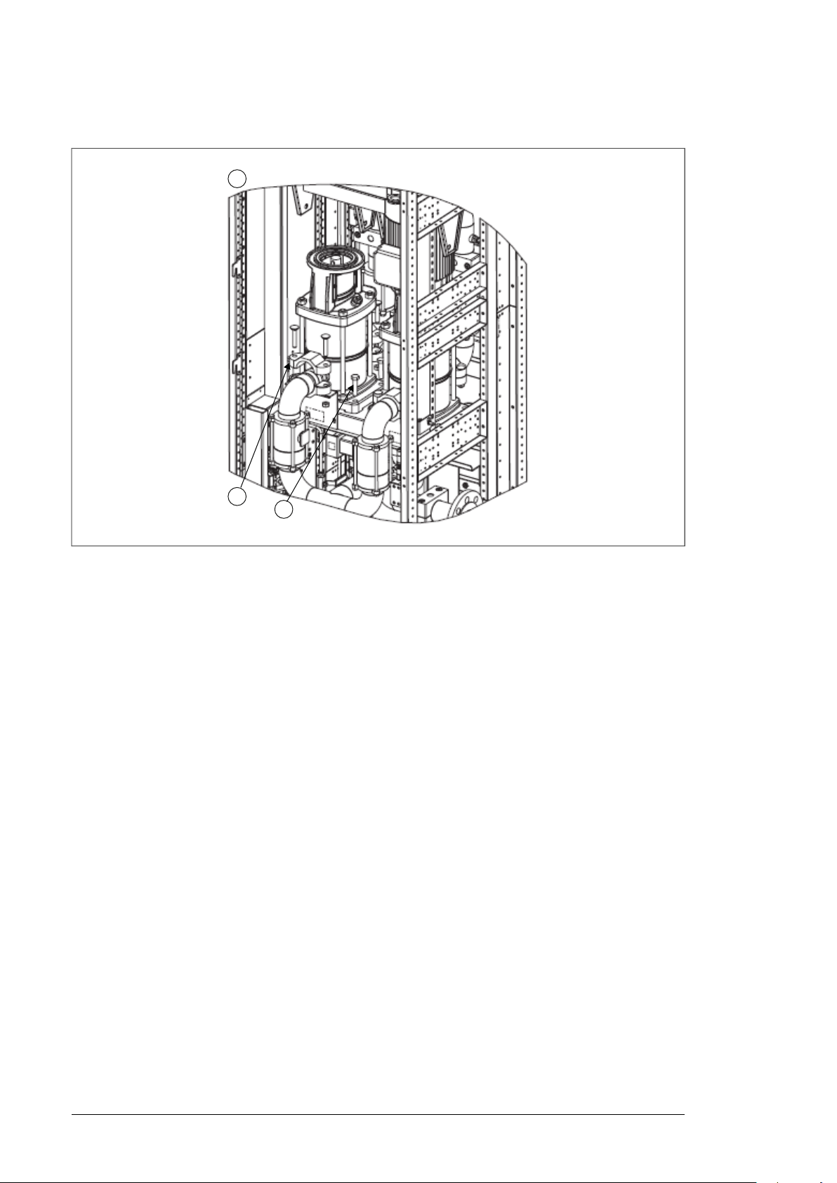
a
b
3
56 Maintenance
6. Install a new pump.
Page 57

Program features
Program features 57
8
What this chapter contains
This chapter describes the features of the control program.
Basics
The cooling unit (LCU) controls the circulation in the internal cooling circuit by switching the
pump on and off. During the normal operation of the drive, the pump runs constantly. The
control program switches the pump off only if:
• It receives a stop command.
• The pump alternation function performs the motor change in a two-pump system (stops
one motor and starts the other).
• The control program detects a fault, such as:
• low pump inlet pressure
• abnormal temperature, pressure or leakage in the internal cooling circuit.
• Motor protective circuit breakers of all pumps have tripped (or opened by user).
• The XSTO circuit on the control unit is open. (Jumper wire is not connected.)
Start/stop control, and reset
See Control interfaces (page 22).
■ Settings and diagnostics
Parameters: 20.03.
Events: -
Page 58

58 Program features
Pump control
■ Basic operation
The control program switches pump(s) on or off via relay outputs: RO1 controls the contactor
of pump 1 motor, RO2 controls the contactor of pump 2 motor (in the two-pump cooling unit
version). The control program monitors the pump power supply via digital inputs: The auxiliary
contacts of the motor protective circuit breakers are wired to the digital inputs: DI1 monitors
pump 1, DI2 pump 2 (in two-pump version). The IO interface related to pump control and
monitoring is fixed, and it cannot be adjusted by the user.
In the two-pump unit:
• One pump is operating at the time.
• Control program alternates pumps automatically at standard. The user can disable the
alternation by a parameter, and force either pump 1 or pump 2 in use.
• User can disconnect one pump from the system, or the control program can do it in
case of a failure. The cooling unit continues with the remaining pump only.
Settings and diagnostics
Parameters: 20.01, 20.02
Events: -
■ Alternation
In a two-pump cooling unit, the control program alternates the pump in duty automatically.
The alternation reduces the wear of an individual pump.
User activates the Alternation function by selecting the Auto control mode in use. The user
also defines the run time periods for the pumps. When the cooling unit receives the start
command, it first starts pump 1, and runs it for the user-defined pump 1 run time. After the
time has passed, the control program stops pump 1 and starts pump 2 for the pump 2 run
time, etc.
Settings and diagnostics
Parameters: 20.01, 20.0220.04, 20.05, 20.06,
Events: -
■ Redundancy
The two-pump cooling unit is redundant. Since only one pump runs at the time, the unit can
continue the operation also in case the other pump is out of use due to failure or maintenance.
For example, the cooling unit detects if the motor protective circuit breaker of a pump is
open: it will not try to start that pump but runs only the other pump until it is possible to return
to normal two-pump operation with alternation. To enable the redundancy, you must have
the Auto control mode in use.
Settings and diagnostics
Parameters: 20.01
Events: -
Page 59

Program features 59
■ Standby
The Standby function is useful in applications where the drive and the cooling unit are
stopped for long time periods. A long non-operational standby time will dry up the pump,
which can damage the sealing or bearings.
When the Standby function is active, the control program runs the pump automatically in
user-defined cycles. The user can activate the function and define the stop and run times
with parameters. In a two-pump cooling unit, the function operates both pumps: first pump 1,
then pump 2. The user-defined run time is divided to half between the pumps. Note that the
control program will use the same time setting for two purposes: It is the run time for the
Standby function, and also the delay time for the Delayed cooling function.
Settings and diagnostics
Parameters: 20.07, 20.08, 20.09
Events: -
■ Delayed cooling
User activates the Delayed cooling function by defining a stop delay. When the control
program receives the stop command, it keeps the pump running for the stop delay time.
Settings and diagnostics
Parameters: 20.07
Events: -
Pressure monitoring functions
The pressure monitoring functions supervise:
• the pump inlet pressure vs. user-defined minimum limit, and sensor status
• the pump outlet pressure vs. user-defined maximum limit, and sensor status
• the pump pressure difference vs. user-defined minimum limit.
If a function detects that the pump pressure is out of the range, it generates a warning, or
trips the unit on a fault. The user can define the warning and fault limits. For the outlet
pressure monitoring there is only a warning limit. For the pressure difference monitoring
function, there is a resetting parameter: the user must reset the function after a fault trip
before a pump restart is possible.
If a function detects that a sensor is faulty, or not connected, it generates a warning.
■ Operation of the Pressure difference monitoring function
When the pressure difference goes below the warning limit, the function generates a warning
(Pressure difference low). If the pressure difference keeps decreasing and goes below the
fault limit, the one-pump cooling unit trips on a fault. The two-pump unit tries a pump change
as follows:
1.
The function checks if the control mode selection (20.01) allows the automatic pump
alternation:
• If yes, the function changes the pump in duty automatically (ie, stops the pump in
use, and starts the other pump), and continues to step 2.
•
If no, the function trips the unit on a fault (Pumps failed), and the cooling unit stops.
You can start the unit only after repairing the pump, resetting the cooling unit, and
resetting the pressure difference monitoring function (31.20).
Page 60

60 Program features
2.
If the control mode selection (20.01) allowed the pump change, the function keeps
monitoring the pressure difference a few seconds, and then decides on the next steps:
• If the pressure difference goes back to normal, the function considers the stopped
pump to be damaged. The cooling unit continues the operation with one pump only.
The Alternation function does not try to use the damaged pump, and the warning
remains active. The cooling unit goes back to normal two-pump operation only after
the user has repaired the damaged pump and reset the pressure difference
monitoring function (31.20).
• If the pressure difference stays below the fault limit, the function trips the unit on a
fault (Pumps failed), and the cooling unit stops. The user can start the unit only after
repairing the pumps, resetting the cooling unit, and resetting the pressure difference
monitoring function (31.20).
■ Settings and diagnostics
Parameters: 20.01, 31.01, 31.02, 31.03, 31.04, 31.05, 31.06, 31.20.
Events: Inlet pressure, Outlet pressure, Pressure difference low, Inlet pressure, Pressure
difference, Inlet pressure sensor, Outlet pressure sensor.
Temperature monitoring functions
The temperature monitoring functions supervise:
• the coolant temperature level and sensor status
• the internal temperature level (inside the cooling unit cabinet) and sensor status
• the ambient temperature level (outside the cooling unit cabinet) and sensor status.
If a function detects a temperature that is out of the range, or a faulty or not connected
sensor, it generates a warning. The user can define:
• minimum and maximum limits for the coolant temperature monitoring
• maximum limit for the internal temperature monitoring
• minimum and maximum limits for the ambient temperature monitoring.
■ Settings and diagnostics
Parameters: 31.09, 31.10, 31.11, 31.12, 31.13
Events: Coolant temperature below limit, Coolant overtemperature, Coolant temperature
sensor, Cabinet overtemperature, Cabinet temperature sensor, Ambient temperature below
limit, Ambient overtemperature, Ambient temperature sensor
Leakage monitoring function
The leakage monitoring function supervises the leakage sensor on the bottom of the cooling
unit. If the sensor indicates a leakage, the function generates a warning, or trips the unit on
a fault. User can define the action, and the delay time for it.
■ Settings and diagnostics
Parameters: 31.06, 31.07
Events: Coolant leakage (warning), Coolant leakage (fault)
Page 61

Program features 61
Miscellaneous
■ User lock
For better cybersecurity, it is highly recommended that you set a master pass code to prevent
eg. the changing of parameter values and/or the loading of firmware and other files.
WARNING!
ABB will not be liable for damages or losses caused by the failure to activate the
user lock using a new pass code. See Cybersecurity disclaimer.
To activate the user lock for the first time,
•
Enter the default pass code, 10000000, into 96.02. This will make parameters
96.100…96.102 visible.
• Enter a new pass code into 96.100 Change user pass code. Always use eight digits; if
using Drive composer, finish with Enter.
• Confirm the new pass code in 96.101 Confirm user pass code.
WARNING!
Store the pass code in a safe place – the user lock cannot be opened even
by ABB if the pass code is lost.
• In 96.102 User lock functionality, define the actions that you want to prevent (we
recommend you select all the actions unless otherwise required by the application).
•
Enter an invalid (random) pass code into 96.02.
•
Activate control board boot (96.08), or cycle the power to the control unit.
• Check that parameters 96.100…96.102 are hidden. If they are not, enter another random
pass code into 96.02.
To reopen the lock, enter your pass code into 96.02. This will again make parameters
96.100…96.102 visible.
Settings and diagnostics
Settings: 96.02, and 96.100…96.102
Page 62

62
Page 63

Parameters
Parameters 63
9
Terms and abbreviations
DefinitionTerm
Actual signal
Def
FbEq16
Other
Other [bit]
Type of parameter that is the result of a measurement or calculation by the control program,
or contains status information. Most actual signals are read-only, but some (especially countertype actual signals) can be reset.
(In the following table, shown on the same row as the parameter name). The default value of
a parameter.
(In the following table, shown on the same row as the parameter range, or for each selection)
16-bit fieldbus equivalent: The scaling between the value shown on the panel and the integer
used in communication when a 16-bit value is selected for transmission to an external system.
A dash (-) indicates that the parameter is not accessible in 16-bit format.
The value is taken from another parameter. Choosing "Other" displays a parameter list in
which the user can specify the source parameter.
Note: The source parameter must be a 32-bit real (floating point) number. To use a 16-bit
integer (for example, received from an external device in data sets) as the source, data storage
parameters can be used.
The value is taken from a specific bit in another parameter. Choosing "Other" displays a
parameter list in which the user can specify the source parameter and bit.
Either a user-adjustable operating instruction for the control program, or an actual signal.Parameter
Per unitp.u.
01 Actual values
Def/FbEq16DescriptionName/ValueNo.
Basic signals for monitoring the unit.01 Actual values
0.0 barShows the coolant inlet pressure for pump(s).Inlet pressure01.01
1000 = 1 barPressure0.0…10.0 bar
Page 64

64 Parameters
04 Warnings and faults
Information on warnings and faults that occurred last.04 Warnings and faults
All parameters in this group are read-only unless otherwise
noted.
Tripping fault04.01
the current fault trip).
Def/FbEq16DescriptionName/ValueNo.
0.0 barShows the outlet pressure for pump(s).Outlet pressure01.02
1000 = 1 barPressure0.0…10.0 bar
0.0 barShows the pressure difference over pump inlet and outlet.Pressure difference01.03
1000 = 1 barPressure0.0…10.0 bar
0.0 ºCShows the measured cabinet temperature.Cabinet temperature01.21
100 = 1 ºCTemperature-50.0…150.0 ºC
0.0 ºCShows the cabinet ambient temperature.Ambient temperature01.22
100 = 1 ºCTemperature-40.0…120.0 ºC
0.0 ºCShows the coolant temperature in the internal cooling circuit.Coolant temperature01.23
100 = 1 ºCTemperature-10.0…60.0 ºC
Def/FbEq16DescriptionName/ValueNo.
-Shows the code of the 1st active fault (the fault that caused
1 = 11st active fault.0000h…FFFFh
-Shows the code of the 2nd active fault.Active fault 204.02
1 = 12nd active fault.0000h…FFFFh
-Shows the code of the 3rd active fault.Active fault 304.03
1 = 13rd active fault.0000h…FFFFh
-Shows the code of the 4th active fault.Active fault 404.04
1 = 14th active fault.0000h…FFFFh
-Shows the code of the 5th active fault.Active fault 504.05
1 = 15th active fault.0000h…FFFFh
-Shows the code of the 1st active warning.Active warning 104.06
1 = 11st active warning.0000h…FFFFh
-Shows the code of the 2nd active warning.Active warning 204.07
1 = 12nd active warning.0000h…FFFFh
-Shows the code of the 3rd active warning.Active warning 304.08
1 = 13rd active warning.0000h…FFFFh
-Shows the code of the 4th active warning.Active warning 404.09
1 = 14th active warning.0000h…FFFFh
-Shows the code of the 5th active warning.Active warning 504.10
1 = 15th active warning.0000h…FFFFh
-Shows the code of the 1st stored (non-active) fault.Latest fault04.11
1 = 11st stored fault.0000h…FFFFh
-Shows the code of the 2nd stored (non-active) fault.2nd latest fault04.12
1 = 12nd stored fault.0000h…FFFFh
-Shows the code of the 3rd stored (non-active) fault.3rd latest fault04.13
Page 65

Parameters 65
Def/FbEq16DescriptionName/ValueNo.
1 = 13rd stored fault.0000h…FFFFh
-Shows the code of the 4th stored (non-active) fault.4th latest fault04.14
1 = 14th stored fault.0000h…FFFFh
-Shows the code of the 5th stored (non-active) fault.5th latest fault04.15
1 = 15th stored fault.0000h…FFFFh
-Shows the code of the 1st stored (non-active) warning.Latest warning04.16
1 = 11st stored warning.0000h…FFFFh
-Shows the code of the 2nd stored (non-active) warning.2nd latest warning04.17
1 = 12nd stored warning.0000h…FFFFh
-Shows the code of the 3rd stored (non-active) warning.3rd latest warning04.18
1 = 13rd stored warning.0000h…FFFFh
-Shows the code of the 4th stored (non-active) warning.4th latest warning04.19
1 = 14th stored warning.0000h…FFFFh
-Shows the code of the 5th stored (non-active) warning.5th latest warning04.20
1 = 15th stored warning.0000h…FFFFh
Fault word04.21
only.
Pumps failedb0
Inlet pressure lowb3
XSTO openb7
Coolant leakageb10
Coolant temp lowb0
Coolant temp highb1
Inlet pressure lowb2
Outlet overpressureb3
Pressure differenceb4
Cabinet overtempb7
Ambient temp lowb8
Ambient overtempb9
Coolant leakageb13
Pressure diff lowb15
1 = See fault Pumps failed.
1 = See fault Inlet pressure.
1 = Circuit connected from terminal XSTO:OUT to XSTO:IN1
and/or XSTO:IN2 on the control unit is open.
1 = See fault Coolant leakage.
1 = The coolant temperature in the internal cooling circuit is
below the defined limit. See parameter 31.09.
1 = The coolant temperature in the internal cooling circuit
exceeds the defined limit. See parameter 31.10.
1 = Pump inlet pressure is below the defined limit. See
parameter 31.01.
1 = Pump outlet pressure exceeds the defined limit. See
parameter 31.03.
1 = Pressure difference over pump(s) is below the defined
limit. See parameter 31.04.
1 = Cabinet temperature exceeds the defined limit. See
parameter 31.11.
1 = Ambient temperature is below the minimum limit. See
parameter 31.12.
1 = Ambient temperature exceeds the defined limit. See
parameter 31.13.
1 = Coolant leakage in internal/external cooling circuit or
condensation detected.
1 = Pump 1 or 2 motor protective circuit breaker is open.Pump MCBb14
1 = The difference between the pump inlet and outlet pressure is below the defined limit. See parameter 31.04.
-Shows the cooling unit fault word 1. This parameter is read-
1 = 1See below for the bit assignments of the word.0000h…FFFFh
-Shows the warning word 1. This parameter is read-only.Warning word 104.31
1 = 1See below for the bit assignments of the word.0000h…FFFFh
Page 66

66 Parameters
1 = Inlet coolant pressure sensor failureInlet pressure sensorb0
b1
sensor
1 = Outlet coolant pressure sensor failureOutlet pressure
1 = Coolant temperature sensor failureCoolant temp sensorb2
1 = Cabinet temperature sensor failureCabinet temp sensorb3
1 = Ambient temperature sensor failureAmbient temp sensorb4
06 Control and status words
Control and status words.06 Control and status words
All parameters in this group are read-only unless otherwise
noted.
1 = StartStart/Stopb0
1 = ResetResetb7
1 = Pump 1 is active.Pump 1b0
1 = Pump 2 is active.Pump 2b1
06.23
Auto modeb2
Panelb9
Inlet pressure raw
value
1 = Auto mode is selected. See parameter 20.01.
1 = Fault is active.Faultb4
1 = Warning is active.Warningb7
1 = The control panel is in local control mode (and the control
interface for the cooling unit).
Shows the status for digital inputs.DI status06.20
1 = Digital input DIx is on.DI1…DI6b0…b5
1 = Digital input DIIL is on.DIILb15
Shows the status of the digital input/output signals.DIO status06.21
1 = Digital IO DIO1 is active.DIO1b0
1 = Digital IO DIO2 is active.DIO2b1
Shows the status of the relay output signals.RO status06.22
1 = Relay output RO1 is energized.RO1b0
1 = Relay output RO2 is energized.RO2b1
1 = Relay output RO3 is energized.RO3b2
Shows the inlet pressure signal in milliamperes (mA) (value
received from the sensor).
mA signal-22.000…22.000 mA
Def/FbEq16DescriptionName/ValueNo.
-Shows the warning word 2. This parameter is read-only.Warning word 204.32
1 = 1See below for the bit assignments of the word.0000h…FFFFh
Def/FbEq16DescriptionName/ValueNo.
-Shows the cooling unit control word.Control word06.01
1 = 1See below for the bit assignments of the word.0000h…FFFFh
-Shows the cooling unit status word.Status word06.11
1 = 1See below for the bit assignments of the data word.0000h…FFFFh
1 = 1See below for the bit assignments of the data word.0000h…FFFFh
1 = 1See below for the bit assignments of the data word.0000h…FFFFh
1 = 1See below for the bit assignments of the data word.0000h…FFFFh
Page 67

Parameters 67
Def/FbEq16DescriptionName/ValueNo.
06.24
06.25
06.26
06.27
Outlet pressure raw
value
Cabinet temp raw
value
Ambient temp raw
value
Coolant temp raw
value
07 System info
…
Firmware version07.05
…
07.06
07.07
Loading package
name
…
Loading package
version
…
…
Shows the outlet pressure signal in milliamperes (mA) (value
received from the sensor).
mA signal-22.000…22.000 mA
Shows the cabinet temperature signal in milliamperes (mA)
(value received from the sensor).
mA signal-22.000…22.000 V
Shows the ambient temperature signal in milliamperes (mA)
(value received from the sensor).
mA signal-22.000…22.000 V
Shows the coolant temperature signal in milliamperes (mA)
(value received from the sensor).
mA signal-22.000…22.000 V
Def/FbEq16DescriptionName/ValueNo.
Information on firmware.07 System info
All parameters in this group are read-only.
-Shows the firmware identifier.Firmware name07.04
-Shows the firmware version number. The format is A.BB.C.D,
where A = major version, B = minor version, C = patch (ie.
firmware variant code), D = 0.
-Shows the name of the firmware loading package. The format
is ALCLX, where X denotes the control unit type (2 = BCUx2, 6 = ZCU-12/14).
-Shows the version number of the firmware loading package.
Format: See parameter 07.05.
-Shows the version number of the firmware bootloader.Bootloader version07.08
-Shows the microprocessor load in percent.Cpu usage07.11
1 = 1%Microprocessor load.0…100%
20 LCU control and settings
Cooling unit control and settings.20 LCU control and settings
Manual
into use by parameter 20.02.
Auto
Auto control mode. The cooling unit control logic selects
pump 1 or pump 2 into use automatically. See Alterna-
tion (page 58).
Def/FbEq16DescriptionName/ValueNo.
1Selects the control mode of the cooling unit.Control mode20.01
0Manual control mode. User forces either pump 1 or pump 2
1
Page 68

68 Parameters
Def/FbEq16DescriptionName/ValueNo.
Pump selection20.02
Control location20.03
DDCS controller
Fieldbus A
1 pump
2 pumps
Run time period P120.05
Run time period P220.06
Stop delay20.07
If parameter 20.01 has value Manual, this parameter defines
the pump in use (pump 1 or pump 2).
the start/stop signal.
Note: This selection is only effective when the control location
selection from the control panel is Remote. If it is Local, the
control panel is the sole source for the start/stop.
the control unit is equipped with the FDCO adapter module
(option +L508).
Fieldbus adapter A. Applicable only when the control unit is
equipped with a fieldbus adapter module (option +K4xx). See
Fieldbus control through a fieldbus adapter (page 97).
If you select it for a two-pump unit, the control program will
disable pump 2 and the automatic pump alternation feature,
and operates only pump 1.
standard.
Defines run time period for pump 1 in a two-pump cooling
unit when the automatic alternation is in use. See section
Alternation (page 58).
Defines run time period for pump 2 in a two-pump cooling
unit when the automatic alternation is in use. See Alterna-
tion (page 58).
Tune this value on site if a delayed cooling period after the
stop is needed.
1
1 = 1Pump 1, pump 21…2
1Selects the interface through which the cooling unit reads
1Digital input DI6. 1 = start, 0 = stop.Local control
2Serial DDCS channel (fibre optic link). Applicable only when
3
2Defines the number of pumps in operation.Number of pumps20.04
11 pump. Use this value value for the one-pump cooling unit.
22 pumps. Use this value for a two-pump cooling unit as
3 d
1 = 1 dTime1…7 d
3 d
1 = 1 dTime1…7 d
10 minDefines the running time of pump(s) after the stop command.
Standby enable20.08
Standby delay20.09
Edge
Note: This parameter also defines the time for the Standby
function (20.08).
Enables the Standby function. See Standby (page 59).
Defines the delay time for the Standby function (20.08).
Selects the trigger type for the start/stop signal.Start trigger type20.11
edge of the signal (1 -> 0).
1 = 1 minTime10…60 min
On
1 = 1Enable (1), disable (0)Off (0)…on (1)
7 d
1 = 1 dTime in days1…21 d
0Start at the rising edge of the signal (0-> 1), stop at the falling
1Start signal on (1) = start, start signal off (0) = stop.Level
Page 69

31 Fault functions
Parameters 69
Def/FbEq16DescriptionName/ValueNo.
31 Fault functions
31.01
31.02
31.03
31.09
31.10
31.11
31.12
31.13
31.20
Inlet pressure min
warning
Inlet pressure min
fault
Outlet pressure max
warning
Pressure diff warning31.04
Pressure diff fault31.05
Leakage action31.06
Warning
Fault
Leakage delay31.07
Coolant min temperature
Coolant max temperature
Cabinet max temperature
Ambient min temperature
Ambient max temperature
Pressure difference
reset
Done
Configuration of external events; selection of behavior of the
unit upon fault situations.
(Inlet pressure).
Defines minimum inlet pressure for the fault (Inlet pressure).
Defines maximum outlet pressure for warning (Outlet pres-
sure).
Defines the minimum pressure difference for warning (Pres-
sure difference low).
(Pressure difference).
leakage.
Warning (Coolant leakage).
Fault (Coolant leakage).
Defines the delay for the leakage function (31.06.
in the internal cooling circuit (Coolant temperature below
limit).
in the internal cooling circuit (Coolant overtemperature).
(Cabinet overtemperature).
(Ambient temperature below limit).
ure (Ambient overtemperature).
after fixing the cause for the pressure difference fault/warning.
reset)
1.0 barDefines the minimum pump inlet pressure for the warning
10 = 1 barPressure value0.0…10.0 bar
0.5 bar
10 = 1 barPressure value0.0…10.0 bar
6.0 bar
10 = 1 barPressure value0.0…10.0 bar
2.0 bar
10 = 1 barPressure value0.0…10.0 bar
1.5 barDefines the minimum pressure difference limit for fault
10 = 1 barPressure value0.0…10.0 bar
FaultSelects the action in case the control program detects a
0
1
0 min
1 = 1 sDelay0…500 min
5.0 ºCDefines the warning limit of the minimum liquid temperature
100 = 1 ºCTemperature0.0…40.0 ºC
45.0 ºCDefines the warning limit of the maximum liquid temperature
100 = 1 ºCTemperature0.0…70.0 ºC
55.0 ºCDefines the warning limit of the maximum cabinet temperature
100 = 1 ºCTemperature-10.0…70.0 ºC
5.0 ºCDefines the warning limit of the minimum ambient temperature
100 = 1 ºCTemperature-10.0…60.0 ºC
55.0 ºCDefines the warning limit of the maximum ambient temperat-
100 = 1 ºCTemperature-10.0…60.0 ºC
1Resets the pressure difference monitoring function. Reset
0Done (control program restores automatically this value after
1ResetReset
Page 70

70 Parameters
47 Data storage
Def/FbEq16DescriptionName/ValueNo.
47 Data storage
2147473.264
2147473.264
2147483647
2147483647
Data storage parameters that can be written to and read
from using other parameters’ source and target settings.
Note that there are different storage parameters for different
data types. Integer-type storage parameters cannot be used
as the source of other parameters.
0.000Shows the real-type data storage parameter 1.Data storage 1 real3247.01
Parameters 47.01…47.08 are real 32-bit numbers that can
be used as source values of other parameters.
32-bit real (floating point) number.2147483.264 …
…………
0.000Shows the real-type data storage parameter 8.Data storage 8 real3247.08
32-bit real (floating point) number.2147483.264 …
0Shows the 32-bit integer-type data storage parameter 1.Data storage 1 int3247.11
-32-bit integer.-2147483648 …
…………
0Shows the 32-bit integer-type data storage parameter 8.Data storage 8 int3247.18
-32-bit integer.-2147483648 …
0Shows the 16-bit integer-type data storage parameter 1.Data storage 1 int1647.21
1 = 116-bit integer-32768…32767
…………
0Shows the 16-bit integer-type data storage parameter 8.Data storage 8 int1647.28
1 = 116-bit integer.-32768…32767
49 Panel port communication
Communication settings for the control panel port.49 Panel port communication
Node ID number49.01
network must have a unique node ID.
Note: For networked drives/units, it is advisable to reserve
ID 1 for spare or replacement drive/unit.
Def/FbEq16DescriptionName/ValueNo.
1Defines the node ID of the unit. All devices connected to the
1 = 1Node ID.1…32
230.4 kbpsDefines the transfer rate of the linkBaud rate49.03
138.4 kbit/s38.4 kbps
257.6 kbit/s57.6 kbps
386.4 kbit/s86.4 kbps
4115.2 kbis/s115.2 kbps
5230.4 kbit/s230.4 kbps
Page 71

Parameters 71
Def/FbEq16DescriptionName/ValueNo.
49.04
49.05
Communication loss
time
Communication loss
action
Fault
Warning
Refresh settings49.06
If a communication break lasts longer than the timeout, the
action specified by parameter 49.05 Communication loss
action is taken
communication break. Changes to this parameter take effect
after the control unit is rebooted or the new settings validated
by parameter 49.06 Refresh settings.
Unit trips (Control panel loss). This only occurs if control is
expected from the control panel (it is selected as source of
start/stop in the currently active control location).
Control program generates a warning (Control panel loss).
This only occurs if control is expected from the control panel
(it is selected as source of start/stop in the currently active
control location).
WARNING!
Make sure that it is safe to continue operation in case
of a communication break.
Applies to parameters 49.01…49.05.
10.0 sSets a timeout for control panel (or PC tool) communication.
10 = 1 sPanel/PC tool communication timeout.0.3…3000.0s
FaultSelects how the unit reacts to a control panel (or PC tool)
0No action takenNo action
1
2Not in use.Last speed
3Not in use.Speed ref safe
5
Done
Note: Refreshing may cause a communication break, so reconnecting the unit may be required.
Refresh
Refresh parameters 49.01…49.05. The value reverts automatically to Done.
50 Fieldbus adapter (FBA)
Fieldbus communication configuration.50 Fieldbus adapter (FBA)
FBA A enable50.01
fieldbus adapter A, and specifies the slot the adapter is installed into.
Option slot 1
The adapter is in slot 1.
Option slot 2
The adapter is in slot 2.
Option slot 3
The adapter is in slot 3.
50.02
FBA A comm loss
func
Fault
break. A time delay for the action can be defined by parameter 50.03. See also parameter 50.26.
Unit trips (FBA A communication). This only occurs if control
is expected from the FBA A interface (FBA A selected as
source of start/stop), or if supervision is forced using parameter 50.26.
0Refresh done or not requested.Done
1
Def/FbEq16DescriptionName/ValueNo.
DisableEnables/disables communication between the unit and
0Communication between unit and fieldbus adapter A disabled.Disable
1Communication between unit and fieldbus adapter A enabled.
2Communication between unit and fieldbus adapter A enabled.
3Communication between unit and fieldbus adapter A enabled.
No actionSelects how the unit reacts upon a fieldbus communication
0No action taken.No action
1
Page 72

72 Parameters
Fault always
Warning
50.03
FBA A comm loss t
out
Unit trips (FBA A communication). This occurs even though
no control is expected from the FBA A interface.
Unit generates a warning (FBA A communication). This only
occurs if control is expected from the FBA A interface, or if
supervision is forced using parameter 50.26.
WARNING!
Make sure that it is safe to continue operation in case
of a communication break.
50.02 is taken. Time count starts when the communication
link fails to update the message.
As a rule of thumb, this parameter should be set to at least
3 times the transmit interval of the master.
Note: There is a 60-second boot-up delay immediately after
power-up. During the delay, the communication break monitoring is disabled (but communication itself can be active).
Def/FbEq16DescriptionName/ValueNo.
2Not in use.Last speed
3Not in use.Speed ref safe
4
5
0.3 sDefines the time delay before the action defined by parameter
50.09
FBA A actual 1 type50.07
Transparent
General
FBA A actual 2 type50.08
…
FBA A SW transparent source
Other
Time delay.0.3…6553.5 s
transmitted to the fieldbus network through fieldbus adapter
A.
Note: Fieldbus-specific communication profiles may use different scalings. For more information, see the manual of the
fieldbus adapter.
The value selected by parameter 50.10 is sent as actual
value act1. No scaling is applied (the 16-bit scaling is 1 = 1
unit).
The value selected by parameter 50.10 is sent as actual
value act1 with a 16-bit scaling of 100 = 1 unit (ie. integer
and two decimals).
Note in use.Torque
Note in use.Speed
Note in use.Frequency
transmitted to the fieldbus network through fieldbus adapter
A.
See parameter 50.07 .
when the fieldbus adapter A is set to a transparent communication profile eg. by its configuration parameters (group 51
FBA A settings).
Other source. See Terms and abbreviations (page 63).
AutoNot in use.FBA A ref1 type50.04
0Not in use.…
AutoSelects the type/source and scaling of actual value act1
0Note in use.Auto
1
AutoSelects the type/source and scaling of actual value act2
0Note in use.Auto
1
6Note in use.Frequency
Not selectedSelects the source of the fieldbus adapter A status word (SW)
0No source selected.Not selected
Page 73

Parameters 73
Def/FbEq16DescriptionName/ValueNo.
50.10
50.11
FBA A act1 transparent source
Other
FBA A act2 transparent source
Other
FBA A debug mode50.12
FBA A control word50.13
FFFFFFFFh
FBA A status word50.16
FFFFFFFFh
FBA A actual value 150.17
2147483648
FBA A actual value 250.18
2147483648
When parameter 50.07 is set to Transparent or General, this
parameter selects the source of actual value act1 transmitted
to the fieldbus network through fieldbus adapter A.
Other source. See Terms and abbreviations (page 63).
When parameter 50.08 is set to Transparent or General, this
parameter selects the source of actual value act2 transmitted
to the fieldbus network through fieldbus adapter A.
Other source. See Terms and abbreviations (page 63).
and sent to fieldbus adapter A in parameters 50.13…50.18.
This functionality should only be used for debugging.
master (PLC) to fieldbus adapter A if debugging is enabled
by parameter 50.12.
This parameter is read-only.
Control word sent by master to fieldbus adapter A.00000000h …
adapter A to the master (PLC) if debugging is enabled by
parameter 50.12.
This parameter is read-only.
Status word sent by fieldbus adapter A to master.00000000h …
adapter A to the master (PLC) if debugging is enabled by
parameter 50.12.
This parameter is read-only.
Raw ACT1 sent by fieldbus adapter A to master.-2147483648 …
adapter A to the master (PLC) if debugging is enabled by
parameter 50.12.
This parameter is read-only.
Raw ACT2 sent by fieldbus adapter A to master.-2147483648 …
Not selected
0No source selected.Not selected
Not selected
0No source selected.Not selected
DisableEnables the display of raw (unmodified) data received from
0Display of raw data from fieldbus adapter A disabled.Disable
1Display of raw data from fieldbus adapter A enabled.Fast
00.00.00.00Displays the raw (unmodified) control word sent by the
0Not in use.FBA A reference 150.14
0Not in use.FBA A reference 250.15
00.00.00.00Displays the raw (unmodified) status word sent by fieldbus
0Displays raw (unmodified) actual value act1 sent by fieldbus
0Displays raw (unmodified) actual value act2 sent by fieldbus
Page 74

74 Parameters
Def/FbEq16DescriptionName/ValueNo.
50.26
50.32
50.33
FBA A timelevel sel50.21
Monitoring
sion force
FBA B enable50.31
Option slot 1
Option slot 2
Option slot 3
func
timeout
FBA B actual 1 type50.37
FBA B actual 2 type50.38
NormalSelects the communication time levels for fieldbus adapter
A. In general, lower time levels of read/write services reduce
CPU load. The table below shows the time levels of the
read/write services for cyclic high and cyclic low data with
each parameter setting.
Cyclic low **Cyclic high *Selection
2 ms10 msMonitoring
10 ms2 msNormal
2 ms500 usFast
2 ms250 usVery fast
* Cyclic high data consists of fieldbus Status word, Act1 and
Act2.
** Cyclic low data consists of the parameter data mapped to
parameter groups 52 and 53, and acyclic data.
Control word, Ref1 and Ref2 are handled as interrupts generated on receipt of cyclic high messages.
0Normal speed.Normal
1Fast speed.Fast
2Very fast speed.Very fast
3Low speed. Optimized for PC tool communication and monitoring usage.
0000bNot in use.FBA A comm supervi-
……
DisableEnables/disables communication between the unit and
fieldbus adapter B, and specifies the slot the adapter is installed into.
0Communication between unit and fieldbus adapter B disabled.Disable
1Communication between unit and fieldbus adapter B enabled.
The adapter is in slot 1.
2Communication between unit and fieldbus adapter B enabled.
The adapter is in slot 2.
3Communication between unit and fieldbus adapter B enabled.
The adapter is in slot 3.
No actionNot in use.FBA B comm loss
0……
0.3 sNot in use.FBA B comm loss
AutoSelects the type/source and scaling of actual value act1
transmitted to the fieldbus network through fieldbus adapter
B. See parameter 50.07.
……
AutoSelects the type/source and scaling of actual value act2
transmitted to the fieldbus network through fieldbus adapter
B. See parameter 50.07.
……
Page 75

Parameters 75
Def/FbEq16DescriptionName/ValueNo.
50.39
50.40
50.41
FBA B SW transparent source
Other
FBA B act1 transparent source
Other
FBA B act2 transparent source
Other
FBA B debug mode50.42
FBA B control word50.43
FFFFFFFFh
FBA B reference 150.44
2147483648
FBA B reference 250.45
2147483648
FBA B status word50.46
FFFFFFFFh
FBA B actual value 150.47
2147483648
when the fieldbus adapter B is set to a transparent communication profile eg. by its configuration parameters (group
54).
Other source. See Terms and abbreviations (page 63).
When parameter 50.37 is set to Transparent or General, this
parameter selects the source of actual value act1 transmitted
to the fieldbus network through fieldbus adapter B.
Other source. See Terms and abbreviations (page 63).
When parameter 50.38 is set to Transparent or General, this
parameter selects the source of actual value act2 transmitted
to the fieldbus network through fieldbus adapter B.
No source selected.Not selected
Other source. See Terms and abbreviations (page 63).
and sent to fieldbus adapter B in parameters 50.43…50.48.
This functionality should only be used for debugging.
by the master (PLC) to fieldbus adapter B if debugging is
enabled by parameter 50.42.
This parameter is read-only.
(PLC) to fieldbus adapter B if debugging is enabled by
parameter 50.42.
This parameter is read-only.
Raw REF1 sent by master to fieldbus adapter B.-2147483648 …
(PLC) to fieldbus adapter B if debugging is enabled by
parameter 50.42.
This parameter is read-only.
Raw REF2 sent by master to fieldbus adapter B.-2147483648 …
adapter B to the master (PLC) if debugging is enabled by
parameter 50.42.
This parameter is read-only.
Status word sent by fieldbus adapter B to master.00000000h …
adapter B to the master (PLC) if debugging is enabled by
parameter 50.42.
This parameter is read-only.
Raw ACT1 sent by fieldbus adapter B to master.-2147483648 …
Not selectedSelects the source of the fieldbus adapter B status word
0No source selected.Not selected
Not selected
0No source selected.Not selected
Not selected
DisableEnables the display of raw (unmodified) data received from
0Display of raw data from fieldbus adapter B disabled.Disable
1Display of raw data from fieldbus adapter B enabled.Fast
00.00.00.00Not in use. Displays the raw (unmodified) control word sent
-Control word sent by master to fieldbus adapter B.00000000h …
0Displays raw (unmodified) reference REF1 sent by the master
0Displays raw (unmodified) reference REF2 sent by the master
00.00.00.00Displays the raw (unmodified) status word sent by fieldbus
0Displays raw (unmodified) actual value act1 sent by fieldbus
Page 76

76 Parameters
Def/FbEq16DescriptionName/ValueNo.
50.56
FBA B actual value 250.48
2147483648
Monitoring
sion force
0Displays raw (unmodified) actual value act2 sent by fieldbus
adapter B to the master (PLC) if debugging is enabled by
parameter 50.42.
This parameter is read-only.
Raw ACT2 sent by fieldbus adapter B to master.-2147483648 …
NormalSelects the communication time levels.FBA B timelevel sel50.51
In general, lower time levels of read/write services reduce
CPU load. The table below shows the time levels of the
read/write services for cyclic high and cyclic low data with
each parameter setting.
Cyclic low **Cyclic high *Selection
2 ms10 msMonitoring
10 ms2 msNormal
2 ms500 usFast
2 ms250 usVery fast
* Cyclic high data consists of fieldbus Status word, Act1 and
Act2.
** Cyclic low data consists of the parameter data mapped to
parameter groups 55 and 56, and acyclic data.
Control word, Ref1 and Ref2 are handled as interrupts generated on receipt of cyclic high messages.
0Normal speed.Normal
1Fast speed.Fast
2Very fast speed.Very fast
3Low speed. Optimized for PC tool communication and monitoring usage.
0000bNot in use.FBA B comm supervi-
Activates fieldbus communication monitoring separately for
each control location. The parameter is primarily intended
for monitoring the communication with FBA B when it is
connected to the application program and not selected as a
control source by parameters.
……
51 FBA A settings
Def/FbEq16DescriptionName/ValueNo.
Fieldbus adapter A configuration.51 FBA A settings
-Displays the type of the connected fieldbus adapter module.FBA A type51.01
0 = Module is not found or is not properly connected, or is
disabled by parameter 50.01 FBA A enable; 1 = PROFIBUSDP; 32 = CANopen; 37 = DeviceNet; 128 = Ethernet; 132 =
PROFInet IO; 135 = EtherCAT; 136 = ETH Pwrlink; 485 =
RS-485; 62944 = SERCOS; 101 = ControlNet; 47808 =
BACnet/IP; 2222 = Ethernet/IP; 502 = Modbus/TCP
This parameter is read-only.
Page 77

51.29
51.30
51.31
FBA A Par2651.26
FBA A par refresh51.27
FBA A par table ver51.28
FBA A drive type
code
FBA A mapping file
ver
D2FBA A comm
status
Time out
Configuration error
On-line
FBA A comm SW ver51.32
Parameters 51.02…51.26 are adapter module specific. For
more information, see the documentation of the fieldbus adapter module. Note that not all of these parameters are necessarily in use.
See parameter 51.02.
settings (adapter A). After refreshing, the value reverts
automatically to Done.
Note: This parameter cannot be changed while the unit is
running.
module mapping file (stored in the memory of the unit).
In format axyz, where ax = major table revision number; yz
= minor table revision number.
This parameter is read-only.
mapping file (stored in the memory of the unit).
This parameter is read-only.
stored in the memory of the unit in decimal format.
This parameter is read-only.
nication.
adapter and the unit.
system of the unit, or mapping file upload has failed more
than three times.
been configured not to detect a communication break. For
more information, see the documentation of the fieldbus adapter.
Displays the patch and build versions of the adapter module
firmware in format xxyy, where xx = patch version number,
yy = build version number.
Example: C802 = 200.02 (patch version 200, build version
2).
Parameters 77
Def/FbEq16DescriptionName/ValueNo.
0Displays fieldbus adapter A parameter 2.FBA A Par251.02
1 = 1Fieldbus adapter configuration parameter.0…65535
………
0
1 = 1Fieldbus adapter configuration parameter.0…65535
DoneValidates any changed fieldbus adapter module configuration
0Refreshing done.Done
1Refreshing.Refresh
0 hexDisplays the parameter table revision of the fieldbus adapter
-Parameter table revision of adapter module.
0Displays the unit type code in the fieldbus adapter module
1 = 1Unit type code stored in the mapping file.0…65535
0Displays the fieldbus adapter module mapping file revision
1 = 1Mapping file revision.0…65535
-Displays the status of the fieldbus adapter module commu-
0Adapter is not configured.Not configured
1Adapter is initializing.Initializing
2A timeout has occurred in the communication between the
3Adapter configuration error: mapping file not found in the file
4Fieldbus communication is off-line.Off-line
5Fieldbus communication is on-line, or fieldbus adapter has
6Adapter is performing a hardware reset.Reset
Page 78

78 Parameters
FBA A appl SW ver51.33
52 FBA A data in
Def/FbEq16DescriptionName/ValueNo.
-Patch and build versions of adapter module firmware.
Displays the major and minor versions of the adapter module
firmware in format xyy, where x = major revision number, yy
= minor revision number.
Example: 300 = 3.00 (major version 3, minor version 00).
-Major and minor versions of adapter module firmware.
Def/FbEq16DescriptionName/ValueNo.
52 FBA A data in
FBA A data in152.01
Other
FBA A data in252.02
FBA A data in1252.12
Selection of data to be transferred from the cooling unit to
fieldbus controller through fieldbus adapter A.
Note: 32-bit values require two consecutive parameters.
Whenever a 32-bit value is selected in a data parameter, the
next parameter is automatically reserved.
Parameters 52.01…52.12 select data to be transferred from
the unit to the fieldbus controller through fieldbus adapter A.
Note: The cooling unit writes its status word (SW) to the
fieldbus adapter status word as standard despite of parameter
values in this parameter group.
Other source. See Terms and abbreviations (page 63).
See parameter 52.01.
See parameter 52.01.
None
0None.None
1Control Word (16 bits)CW 16bit
2Reference REF1 (16 bits)Ref1 16bit
3Reference REF2 (16 bits)Ref2 16bit
4Status Word (16 bits)SW 16bit
5Actual value act1 (16 bits)Act1 16bit
6Actual value act2 (16 bits)Act2 16bit
11Control Word (32 bits)CW 32bit
12Reference REF1 (32 bits)Ref1 32bit
13Reference REF2 (32 bits)Ref2 32bit
14Status Word (32 bits)SW 32bit
15Actual value act1 (32 bits)Act1 32bit
16Actual value act2 (32 bits)Act2 32bit
24Status Word 2 (16 bits)SW2 16bit
-
None
…………
None
…………
Page 79

53 FBA A data out
Parameters 79
Def/FbEq16DescriptionName/ValueNo.
53 FBA A data out
FBA A data out153.01
Other
FBA A data out253.02
FBA A data out1253.12
Selection of data to be transferred from fieldbus controller
to cooling unit through fieldbus adapter A.
Note: 32-bit values require two consecutive parameters.
Whenever a 32-bit value is selected in a data parameter, the
next parameter is automatically reserved.
Note: The fieldbus control is only possible by the fieldbus
adapter A control word. When you select fieldbus adapter A
as the control location (20.03), and activate the fieldbus adapter A communication (50.01), the cooling unit writers the
fieldbus control word to the cooling unit control word automatically. No other parameters setting is required, or can change
this sole fieldbus control principle.
Parameters 53.01…53.12 select data to be transferred from
the fieldbus controller to the unit through fieldbus adapter A.
Other source. See Terms and abbreviations (page 63).
See parameter 53.01.
See parameter 53.01.
………
None
0None.None
1Control Word (16 bits)CW 16bit
2Reference REF1 (16 bits)Ref1 16bit
3Reference REF2 (16 bits)Ref2 16bit
11Control Word (32 bits)CW 32bit
12Reference REF1 (32 bits)Ref1 32bit
13Reference REF2 (32 bits)Ref2 32bit
21Control Word 2 (16 bits)CW2 16bit
-
None
…………
None
54 FBA B settings
FBB A type54.01
FBA B Par254.02
Fieldbus adapter B configuration.54 FBA B settings
Note: You can use Fieldbus adapter B only for monitoring
purposes, not as the control location/interface.
0 = Module is not found or is not properly connected, or is
disabled by parameter 50.31; 1 = PROFIBUS-DP; 32 =
CANopen; 37 = DeviceNet; 128 = Ethernet; 132 = PROFInet
IO; 135 = EtherCAT; 136 = ETH Pwrlink; 485 = RS-485;
62944 = SERCOS; 101 = ControlNet; 47808 = BACnet/IP;
2222 = Ethernet/IP; 502 = Modbus/TCP.
This parameter is read-only.
Parameters 54.02…54.26 are adapter module-specific. For
more information, see the documentation of the fieldbus adapter module. Note that not all of these parameters are necessarily in use.
Def/FbEq16DescriptionName/ValueNo.
NoneDisplays the type of the connected fieldbus adapter module.
0
Page 80

80 Parameters
FBA B Par2654.26
FBA B par refresh54.27
FBA B par table ver54.28
54.29
54.30
54.31
FBA B drive type
code
FBA B mapping file
ver
status
Time out
Configuration error
On-line
FBA B comm SW ver54.32
See parameter 54.02.
settings. After refreshing, the value reverts automatically to
Done.
Note: This parameter cannot be changed while the unit is
running.
module mapping file (stored in the memory of the unit).
In format axyz, where ax = major table revision number; yz
= minor table revision number.
This parameter is read-only.
mapping file (stored in the memory of the unit).
This parameter is read-only.
stored in the memory of the unit in decimal format.
This parameter is read-only.
Mapping file revision.0…65535
communication.
adapter and the unit.
system of the unit, or mapping file upload has failed more
than three times.
been configured not to detect a communication break. For
more information, see the documentation of the fieldbus adapter.
firmware in format xxyy, where xx = patch version number,
yy = build version number.
Example: C802 = 200.02 (patch version 200, build version
2).
Patch and build versions of adapter module firmware.
Def/FbEq16DescriptionName/ValueNo.
1 = 1Fieldbus adapter configuration parameter.0…65535
………
0
1 = 1Fieldbus adapter configuration parameter.0…65535
DoneValidates any changed fieldbus adapter module configuration
0Refreshing done.Done
1Refreshing.Refresh
0 hexDisplays the parameter table revision of the fieldbus adapter
-Parameter table revision of adapter module.
0Displays the unit type code in the fieldbus adapter module
1 = 1Unit type code stored in the mapping file.0…65535
0Displays the fieldbus adapter module mapping file revision
-Displays the status of the fieldbus adapter moduleD2FBA B comm
0Adapter is not configured.Not configured
1Adapter is initializing.Initializing
2A timeout has occurred in the communication between the
3Adapter configuration error: mapping file not found in the file
4Fieldbus communication is off-line.Off-line
5Fieldbus communication is on-line, or fieldbus adapter has
6Adapter is performing a hardware reset.Reset
0 hexDisplays the patch and build versions of the adapter module
Page 81

Parameters 81
Def/FbEq16DescriptionName/ValueNo.
FBA B appl SW ver54.33
55 FBA B data in
55 FBA B data in
FBA B data in155.01
Other
FBA B data in2255.02
FBA B data in1255.12
firmware in format xyy, where x = major revision number, yy
= minor revision number.
Example: 300 = 3.00 (major version 3, minor version 00).
Major and minor versions of adapter module firmware.
Selection of data to be transferred from cooling unit to fieldbus controller through fieldbus adapter B.
Note: The cooling unit writes its status word (SW) directly
to the fieldbus status word despite of parameter settings in
this group.
Parameters 55.01…55.12 select data to be transferred from
the unit to the fieldbus controller through fieldbus adapter B.
Other source. See Terms and abbreviations (page 63).
See parameter 55.01.
See parameter 55.01.
0 hexDisplays the major and minor versions of the adapter module
Def/FbEq16DescriptionName/ValueNo.
None
0None.None
1Control Word (16 bits)CW 16bit
2Reference REF1 (16 bits)Ref1 16bit
3Reference REF2 (16 bits)Ref2 16bit
4Status Word (16 bits)SW 16bit
5Actual value act1 (16 bits)Act1 16bit
6Actual value act2 (16 bits)Act2 16bit
11Control Word (32 bits)CW 32bit
12Reference REF1 (32 bits). Not in use.Ref1 32bit
13Reference REF2 (32 bits). Not in use.Ref2 32bit
14Status Word (32 bits)SW 32bit
15Actual value act1 (32 bits)Act1 32bit
16Actual value act2 (32 bits)Act2 32bit
24Status Word 2 (16 bits)SW2 16bit
None
…………
None
Page 82

82 Parameters
56 FBA B data out
Def/FbEq16DescriptionName/ValueNo.
56 FBA B data out
FBA B data out156.01
Other
FBA B data out256.02
FBA B data out1256.12
Selection of data to be transferred from fieldbus controller
to cooling unit through fieldbus adapter B.
Note: You can use Fieldbus B only for monitoring purposes,
not as the control location/interface.
Note: The fieldbus control is only possible by the fieldbus
adapter A control word. When you select fieldbus adapter A
as the control location (20.03), and activate the fieldbus adapter A communication (50.01), the cooling unit writers the
fieldbus control word to the cooling unit control word automatically. No other parameters setting is required, or can change
this sole fieldbus control principle.
Parameters 56.01…56.12 select data to be transferred from
the fieldbus controller to the unit through fieldbus adapter B.
Other source. See Terms and abbreviations (page 63).
See parameter 56.01.
See parameter 56.01.
None
0None.None
1Control Word (16 bits).CW 16bit
2Reference REF1 (16 bits).Ref1 16bit
3Reference REF2 (16 bits).Ref2 16bit
11Control Word (32 bits).CW 32bit
12Reference REF1 (32 bits).Ref1 32bit
13Reference REF2 (32 bits).Ref2 32bit
21Control Word 2 (16 bits).CW2 16bit
None
…………
None
…………
60 DDCS communication
DDCS communication configuration.60 DDCS communication
The DDCS protocol is used in the communication between
• units in a master/follower configuration,
• the unit and an external controller such as the AC 800M,
or
• the units of the drive system.
All of the above utilize a fiber optic link which also requires
an FDCO module (typically with ZCU control units) or an
RDCO module (with BCU control units). Master/follower and
external controller communication can also be implemented
through shielded twisted-pair cable connected to the XD2D
connector of the unit.
This group also contains parameters for drive-to-drive (D2D)
communication supervision.
60.51
DDCS controller
comm port
controller (such as an AC 800M).
Def/FbEq16DescriptionName/ValueNo.
Not in useSelects the DDCS channel used for connecting an external
0None (communication disabled).Not in use
Page 83

60.52
60.55
60.56
60.58
DDCS controller
node address
DDCS controller HW
connection
Ring
Star
DDCS controller
baud rate
DDCS controller
comm loss time
Parameters 83
Def/FbEq16DescriptionName/ValueNo.
1Channel A on FDCO module in slot 1.Slot 1A
2Channel A on FDCO module in slot 2.Slot 2A
3Channel A on FDCO module in slot 3.Slot 3A
4Channel B on FDCO module in slot 1.Slot 1B
5Channel B on FDCO module in slot 2.Slot 2B
6Channel B on FDCO module in slot 3.Slot 3B
1Selects the node address of the unit for communication with
the external controller. No two nodes on-line may have the
same address.
With an AC 800M (CI858) DriveBus connection, units must
be addressed 1…24.
With an AC 80 DriveBus connection, units must be addressed
1…12.
With optical ModuleBus, the unit address is set according to
the position value as follows:
1. Multiply the hundreds of the position value by 16.
2. Add the tens and ones of the position value to the result.
For example, if the position value is 101, this parameter must
be set to 1×16 + 1 = 17.
Node address.1..254
StarSelects the topology of the fiber optic link with an external
controller.
0The devices are connected in a ring topology. Forwarding of
messages is enabled.
1The devices are connected in a star topology (for example,
through a branching unit). Forwarding of messages is disabled.
4 mbpsSelects the communication speed of the channel selected
by parameter 60.51.
11 megabit/second.1 mbps
22 megabit/second.2 mbps
44 megabit/second.4 mbps
88 megabit/second.8 mbps
100 msSets a timeout for communication with the external controller.
If a communication break lasts longer than the timeout, the
control program generates a warning (DDCS controller comm
loss). This only occurs if control is expected from the external
controller.
As a rule of thumb, this parameter should be set to at least
3 times the transmit interval of the controller.
Note:
• There is a 60-second boot-up delay immediately after
power-up. During the delay, the communication break
monitoring is disabled (but communication itself can be
active).
• With an AC 800M controller, the controller detects a com-
munication break immediately but re-establishing the
communication is done at 9-second idle intervals. Also
note that the sending interval of a data set is not the same
as the execution interval of the application task. On ModuleBus, the sending interval is defined by controller parameter Scan Cycle Time (by default, 100 ms).
Page 84

84 Parameters
Timeout for communication with external controller.0…60000 ms
60.64
Mailbox dataset selection
the unit/controller communication.
61 D2D and DDCS transmit data
Def/FbEq16DescriptionName/ValueNo.
Dataset 32/33Selects the pair of data sets used by the mailbox service in
0Data sets 32 and 33.Dataset 32/33
1Data sets 24 and 25.Dataset 24/25
Def/FbEq16DescriptionName/ValueNo.
61 D2D and DDCS transmit data
61.51
61.52
61.53
61.54
61.55
Data set 11 data 1
selection
SW 16bit
Fault word
Warning word 1
Warning word 2
DI status
Coolant temperature
Inlet pressure
Outlet pressure
Pressure difference
Cabinet temperature
Ambient temperature
Other
Data set 11 data 2
selection
Data set 11 data 3
selection
Data set 13 data 1
selection
Data set 13 data 2
selection
Defines the data sent to the DDCS link. See also parameter
group 60.
Parameters 61.51…61.74 preselect data to be sent in data
sets 11, 13, 15, 17, 19, 21, 23 and 25 to the external controller.
Parameters 61.101…61.124 display the data to be sent to
the external controller. If no data has been preselected, the
value to be sent can be written directly into these parameters.
For example, this parameter preselects the data for word 1
of data set 11. Parameter 61.101 displays the selected data
in integer format. If no data is preselected, the value to be
sent can be written directly into parameter 62.101.
Status Word (16 bits) (06.01)
Fault word (04.21)
Warning word 1 (04.31)
Warning word 2 (04.32)
DI status (06.20)
Coolant temperature (01.23)
Inlet pressure (01.01)
Outlet pressure (01.02)
Pressure difference (01.03)
Cabinet temperature (01.21)
Ambient temperature (01.22)
Other source. See Terms and abbreviations (page 63).
the external controller. See also parameter 61.102. For the
selections, see parameter 61.51.
the external controller.
See also parameter 61.103.
For the selections, see parameter 61.51.
See parameter 61.51.
See parameter 61.51.
SW 16bit
0None.None
4
1045
1055
1056
1556
279
257
258
259
277
278
Fault wordPreselects the data to be sent as word 2 of data set 11 to
………
Warning word 1Preselects the data to be sent as word 3 of data set 11 to
………
Warning word 2
DI status
Page 85

Parameters 85
Def/FbEq16DescriptionName/ValueNo.
61.56
61.57
61.58
61.59
61.60
61.61
61.62
61.74
61.101
61.102
61.103
61.104
61.124
Data set 13 data 3
selection
Data set 15 data 1
selection
Data set 15 data 2
selection
Data set 15 data 3
selection
Data set 17 data 1
selection
Data set 17 data 2
selection
Data set 17 data 3
selection
Data set 25 data 3
selection
Data set 11 data 1
value
Data set 11 data 2
value
Data set 11 data 3
value
Data set 13 data 1
value
Data set 25 data 3
value
See parameter 61.51.
See parameter 61.51.
See parameter 61.51.
See parameter 61.51.
See parameter 61.51.
See parameter 61.51.
See parameter 61.51.
See parameter 61.51.
controller as word 1 of data set 11.
If no data has been preselected by 61.51 selection, the value
to be sent can be written directly into this parameter.
Data to be sent as word 1 of data set 11.0…65535
controller as word 2 of data set 11.
If no data has been preselected by parameter 61.52, the
value to be sent can be written directly into this parameter.
Data to be sent as word 2 of data set 11.0…65535
controller as word 3 of data set 11.
If no data has been selected by parameter 61.53, the value
to be sent can be written directly into this parameter.
Data to be sent as word 3 of data set 11.0…65535
controller as word 1 of data set 13.
If no data has been selected by parameter 61.54, the value
to be sent can be written directly into this parameter.
Data to be sent as word 1 of data set 13.0…65535
controller as word 3 of data set 25.
If no data has been selected by parameter 61.74, the value
to be sent can be written directly into this parameter.
Data to be sent as word 3 of data set 25.0…65535
Coolant temper-
ature
Inlet pressure
Outlet pressure
Pressure differ-
ence
Cabinet temper-
ature
Ambient temper-
ature
None
………
None
0Displays (in integer format) the data to be sent to the external
0Displays (in integer format) the data to be sent to the external
0Displays (in integer format) the data to be sent to the external
0Displays (in integer format) the data to be sent to the external
…………
0Displays (in integer format) the data to be sent to the external
62 D2D and DDCS receive data
62 D2D and DDCS receive data
Mapping of data received through the DDCS link. See also
parameter group 60 DDCS communication.
Def/FbEq16DescriptionName/ValueNo.
Page 86

86 Parameters
Def/FbEq16DescriptionName/ValueNo.
62.51
62.52
62.53
62.54
62.74
62.101
62.102
62.103
62.104
Data set 10 data 1
selection
Other
Data set 10 data 2
selection
Data set 10 data 3
selection
Data set 12 data 1
selection
Data set 24 data 3
selection
Data set 10 data 1
value
Data set 10 data 2
value
Data set 10 data 3
value
Data set 12 data 1
value
Parameters 62.51…62.74 define a target for the data received in data sets 10, 12, 14, 16, 18, 20, 22 and 24 from
the external controller.
Parameters 62.101…62.124 display the data received from
the external controller in integer format, and can be used as
sources by other parameters.
For example, this parameter selects a target for word 1 of
data set 10. Parameter 62.101 Data set 10 data 1 value displays the received data in integer format, and can also be
used as a source by other parameters.
Other source. See Terms and abbreviations (page 63).
10. See also parameter 62.102. For the selections, see
parameter 62.51.
10. See also parameter 62.103. For the selections, see
parameter 62.51.
See parameter 62.51.
See parameter 62.51.
al controller as word 1 of data set 10.
A target for this data can be selected by parameter 62.51.
The value can also be used as a source by another parameter.
Data received as word 1 of data set 10.0…65535
al controller as word 2 of data set 10.
A target for this data can be selected by parameter 62.52.
The value can also be used as a source by another parameter.
Data received as word 2 of data set 10.0…65535
al controller as word 3 of data set 10.
A target for this data can be selected by parameter 62.53.
The value can also be used as a source by another parameter.
Data received as word 3 of data set 10.0…65535
al controller as word 1 of data set 12.
A target for this data can be selected by parameter 62.54.
The value can also be used as a source by another parameter.
Data received as word 1 of data set 12.0…65535
CW 16bit
0None.None
1Control Word (16 bits)CW 16bit
-
NoneDefines a target for the data received as word 2 of data set
NoneDefines a target for the data received as word 3 of data set
None
…………
None
0Displays (in integer format) the data received from the extern-
0Displays (in integer format) the data received from the extern-
0Displays (in integer format) the data received from the extern-
0Displays (in integer format) the data received from the extern-
…………
Page 87

Parameters 87
Def/FbEq16DescriptionName/ValueNo.
62.124
Data set 24 data 3
value
96 System
96 System
Language96.01
PRC)
Displays (in integer format) the data received from the external controller as word 3 of data set 24.
A target for this data can be selected by parameter 62.74.
The value can also be used as a source by another parameter.
Data received as word 3 of data set 24.0…65535
Def/FbEq16DescriptionName/ValueNo.
Language selection; access levels; macro selection; parameter save and restore; control unit reboot; user parameter
sets; unit selection; data logger triggering; parameter
checksum calculation; user lock.
-Selects the language of the parameter interface and other
displayed information when viewed on the control panel.
Note:
Not all languages listed below are necessarily supported.
This parameter does not affect the languages visible in the
Drive composer PC tool. (Those are specified under View –
Settings.)
0NoneNot selected
1033EnglishEnglish
1031GermanDeutsch
1040ItalianItaliano
3082SpanishEspañol
2070PortuguesePortugues
1043DutchNederlands
1036FrenchFrançais
1030DanishDansk
1035FinnishSuomi
1053SwedishSvenska
1049RussianRusski
1045PolishPolski
1029CzechCzech
2052Simplified ChineseChinese (Simplified,
1055TurkishTürkçe
1041JapaneseJapanese
Page 88

88 Parameters
Def/FbEq16DescriptionName/ValueNo.
96.07
Pass code96.02
Access levels active96.03
Parameter restore96.06
Restore defaults
Clear all
Reset all fieldbus
settings
Parameter save
manually
0Pass codes can be entered into this parameter to activate
further access levels (see parameter 96.03 Access levels
active) or to configure the user lock. Entering “358” toggles
the parameter lock, which prevents the changing of all other
parameters through the control panel or the Drive composer
PC tool.
Note: You must change the default user pass code to
maintain a high level of cybersecurity. Store the code in a
safe place – the protection cannot be disabled even by ABB
if the code is lost.
-Pass code0…99999999
0001hShows which access levels have been activated by pass
codes entered into parameter 96.02 Pass code. This parameter is read-only.
-Active access levels0000h….FFFFh
DoneRestores the original settings of the control program, ie.
parameter default values. This parameter cannot be changed
while the unit is running.
0Restoring is completedDone
8All editable parameter values are restored to default values,
except
• control panel/PC communication settings
• I/O extension module settings
• fieldbus adapter settings
62All editable parameter values are restored to default values,
except control panel/PC communication settings.
PC tool communication is interrupted during the restoring
32Fieldbus adapter and embedded fieldbus interface settings
(parameter groups 50…58) are restored to default values.
This will also restore the default settings of the fieldbus adapter if one is connected
DoneSaves the valid parameter values to permanent memory.
This parameter should be used to store values sent from a
fieldbus, or when using an external power supply to the
control board as the supply might have a very short hold-up
time when powered off.
96.24
Control board boot96.08
Full days since 1st
Jan 1980
Note: A new parameter value is saved automatically when
changed from the PC tool or control panel but not when
altered through a fieldbus adapter connection.
0Save completedDone
1Save in progressSave
0Reboots the control unit (without requiring a power off/on
cycle). The value reverts to 0 automatically.
1 = 11 = Reboot the control unit0…1
-Shows the number of full days passed since beginning of
the year 1980. This parameter, together with 96.25 and 96.26
Time in ms within one minute makes it possible to set the
date and time in the unit via the parameter interface from a
fieldbus or application program. This may be necessary if
the fieldbus protocol does not support time synchronization.
1 = 1Days since beginning of 1980.1…59999
Page 89

Parameters 89
Def/FbEq16DescriptionName/ValueNo.
96.25
96.26
96.29
96.61
Time in minutes within 24 h
Time in ms within one
minute
status
Time tick receivedb0
Aux Time tick re-
b1
ceived
b2
long
DDCS controllerb3
Master/Followerb4
D2Db6
Fbus Ab7
Fbus Bb8
EFBb9
Ethernetb10
Panel linkb11
Ethernet tool linkb12
Parameter settingb13
RTCb14
Drive On-Timeb15
status word
Runningb0
Triggeredb1
For example, the value 860 corresponds to 2:20 pm. See
parameter 96.24.
See parameter 96.24.
priority source.
2nd priority source
controller.
ter/follower link.
ReservedReservedb5
to-drive link.
adapter A.
adapter B.
bedded fieldbus interface.
net port on type BCU control unit.
panel, or Drive composer PC tool connected to the control
panel.
poser PC tool through an FENA module.
96.24…96.26.
1 = RTC time in use: Time and date have been read from
the real-time clock.
on-time.
User data logger status word0000b…1111b
the post-trigger time has passed.
cleared when the logger is restarted.
0 minShows the number of full minutes passed since midnight.
1 = 1Minutes since midnight1…1439
0 msShows the number of milliseconds passed since last minute.
1 = 1Number of milliseconds since last minute.0…59999
-Shows time source status word. This parameter is read-onlyTime sync source
1 = 1See below for the bit assignments of the word.0000h…FFFFh
No Tick1 = 1st priority tick received: Tick has been received from 1st
No Tick1 = 2nd priority tick received: Tick has been received from
No1 = Yes: Tick interval too long (accuracy compromised).Tick interval is too
No Tick1 = Tick received: Tick has been received from an external
No Tick1 = Tick received: Tick has been received through the mas-
No Tick1 = Tick received: Tick has been received through the drive-
No Tick1 = Tick received: Tick has been received through fieldbus
No Tick1 = Tick received: Tick has been received through fieldbus
No Tick1 = Tick received: Tick has been received through the em-
No Tick1 = Tick received: Tick has been received through the Ether-
No Tick1 = Tick received: Tick has been received from the control
No Tick1 = Tick received: Tick has been received from Drive com-
No Tick1 = Tick received: Tick has been set by parameters
RTC time in
use
Not used1 = Drive on-time in use: Time and date are displaying unit
0000bProvides status information on the user data logger.User data logger
01 = The user data logger is running. The bit is cleared after
01 = The user data logger has been triggered. The bit is
Page 90

90 Parameters
Def/FbEq16DescriptionName/ValueNo.
96.63
96.65
Data availableb2
Configuredb3
User data logger trigger
Other [bit]
Other [bit]
time level
Note that the bit is not cleared because the data is saved to
the memory unit.
bit is not cleared because the configuration data is saved to
the memory unit.
ger.
Other source. See Terms and abbreviations (page 63).
Other source. See Terms and abbreviations (page 63).
01 = The user data logger contains data that can be read.
01 = The user data logger has been configured. Note that the
-ReservedReservedb4…b15
OffTriggers, or selects a source that triggers, the user data log-
00Off
11 (triggers)On
-
OffStarts, or selects a source that starts, the user data loggerUser data logger start96.64
00Off
11On
-
500usSelects the sampling interval for the factory data logger.Factory data logger
500500 microseconds500us
20002 milliseconds2ms
1000010 milliseconds10ms
Page 91

Fault tracing
Fault tracing 91
10
What this chapter contains
The chapter lists the warning and fault messages including possible causes and corrective
actions. The causes of most warnings and faults can be identified and corrected using the
information in this chapter. If not, an ABB service representative should be contacted.
Warnings and faults are listed below in separate tables. Each table is sorted by warning/fault
code.
Safety
WARNING!
Only qualified electricians are allowed to service the drive. Before you do any work,
read:
•
Electrical safety precautions (page 29)
• the complete safety instructions. For a multidrive, see the separate safety
instructions manual. For a single drive, see the appropriate drive hardware
manual.
Indications
■ Warnings and faults
Warnings and faults indicate an abnormal drive/unit status. The codes and names of active
warnings/faults are displayed on the control panel as well as the Drive composer PC tool.
Only the codes of warnings/faults are available over fieldbus.
Warnings do not need to be reset; they stop showing when the cause of the warning ceases.
Warnings do not latch and the drive/unit will continue to operate.
Page 92

92 Fault tracing
Faults do latch inside the drive/unit and cause the drive to trip. After the cause of a fault has
been removed, the fault can be reset from a selectable source such as the control panel,
Drive composer PC tool, the digital inputs of the drive/unit, or fieldbus. After the fault is reset,
the drive/unit can be restarted. Note that some faults require a reboot of the control unit
either by switching the power off and on, or using parameter 96.08 Control board boot - this
is mentioned in the fault listing whenever appropriate.
■ Editable messages
For some warnings and faults, the message text can be edited and instructions and contact
information added. To edit these messages, choose Menu - Settings - Edit texts on the
control panel.
Warning/fault history and analysis
■ Event logs
The unit has two event logs that can be accessed from the main Menu on the control panel.
The logs can also be accessed (and reset) using the Drive composer PC tool.
One of the logs contains faults and fault resets. The other log lists warnings and pure events,
as well as clearing entries. Both logs contain the 64 most recent events. All indications are
stored in the event logs with a time stamp and other information.
Factory data logger
The unit has a data logger that samples preselected values at 500-microsecond (default;
see parameter 96.65 Factory data logger time level) intervals. By default, approximately
700 samples recorded immediately before and after a fault, are saved to the memory unit.
The fault data of the last five faults is accessible in the event log when viewed in the Drive
composer pro PC tool. (The fault data is not accessible through the control panel.)
■ Other data loggers
User data logger
A custom data logger can be configured using the Drive composer pro PC tool. This
functionality enables the free selection of up to eight parameters to be sampled at selectable
intervals. The triggering conditions and the length of the monitoring period can also be
defined by the user within the limit of approximately 8000 samples. In addition to the PC
tool, the status of the logger is shown by parameter 96.61 User data logger status word.
The triggering sources can be selected by parameters 96.63 User data logger trigger and
96.64 User data logger start). The configuration, status and collected data is saved to the
memory unit for later analysis.
■ Parameters that contain warning/fault information
The unit is able to store a list of the active faults actually causing the unit to trip at the present
time. The faults are displayed in parameter group 04 Warnings and faults. The parameter
group also displays a list of faults and warnings that have previously occurred.
QR Code generation for mobile service application
A QR Code (or a series of QR Codes) can be generated by the unit for display on the control
panel. The QR Code contains unit identification data, information on the latest events, and
values of status and counter parameters. The code can be read with a mobile device
Page 93

Fault tracing 93
containing the ABB service application, which then sends the data to ABB for analysis. For
more information on the application, contact your local ABB service representative.
Choose Menu - Assistants - QR code on the control panel to generate a QR code.
Warnings
What to doCauseWarningCode
(hex)
A7C1
A7CA
FBA A communication
DDCS controller
comm loss
Control panel lossA7EE
Inlet pressureFF90
Outlet pressureFF91
This is programmable warning (50.02).
Cyclical communication between
cooling unit and fieldbus adapter A or
between PLC and fieldbus adapter A
is lost.
DDCS (fiber optic) communication
between cooling unit and external
controller is lost.
Programmable warning (49.05). Control panel (or PC tool) has stopped
communicating.
Too low pump inlet pressure. Possible
causes:
• excessive minimum warning limit
value.
• leakage in internal cooling circuit
• too low air pressure in expansion
tank
• too low coolant temperature.
Excessive pump outlet pressure. Possible causes:
• too low pressure limit
• closed valve in the cooling system
• excessive temperature in internal
cooling circuit
• dirty, blocked or faulty heat exchanger.
Check status of fieldbus communication.
See user documentation of fieldbus
adapter module.
Check settings of fieldbus adapter A
parameters (50, 51 , 52 and 53).
Check cable connections.
Check if communication master is able
to communicate.
Check status of controller. See user
documentation of controller.
Check DDCS communication parameter settings (60).
Check cable connections. If necessary, replace cables.
Check PC tool or control panel connection.
Check control panel connector.
Check mounting platform if being
used.
Disconnect and reconnect the control
panel.
Check and adjust value of fault function (31.01).
Check that all bleed and drain valves
in internal cooling circuit are closed.
Check and repair any leakage.
Check pressure in expansion tank and
adjust when necessary. See Adjusting
air pressure of the expansion
tank (page 40).
Check limit 31.03 and adjust when
necessary.
Check temperature in internal cooling
circuit (01.23). Make sure that there is
sufficient coolant flow in external
cooling circuit.
Check heat exchanger. Wash and/or
clean it. Replace if it is faulty.
Page 94

94 Fault tracing
(hex)
What to doCauseWarningCode
FF94
Pressure differenceFF92
Inlet pressure sensorFF93
Outlet pressure
sensor
Coolant leakageFF95
Too low pressure difference between
pump outlet and inlet. Possible
causes:
• too high monitoring limit
• improper pump operation
• broken pump impeller .
Inlet pressure sensor is not connected
or it is broken.
Outlet pressure sensor is not connected or it is broken.
Leakage in the internal liquid circuit.
Faulty detector.
Check limit 31.04 and adjust when
necessary.
Check for leakage and repair when
necessary.
Check pump. If you have two-pump
system, test to switch pump in duty.
See parameters 20.01 and 20.02. Replace faulty pump.
Check that cooling circuit is not
blocked by a closed valve.
Note: After you have corrected the
root cause, reset pressure difference
monitoring function (31.20).
Check that sensor is connected to right
terminals. See circuit diagrams.
Replace faulty sensor.
Check that sensor is connected to right
terminals. See circuit diagrams.
Replace faulty sensor.
Repair the leakage point. Dry up the
detector and the bottom of the cooling
unit. If necessary, remove the leakage
detector, open the enclosure, dry the
sensor and re-install.
Replace a faulty detector.
FF97
Pump MCBFF96
Pressure difference
low
Motor protective circuit breaker of
pump has tripped. Possible causes:
• user opened breaker manually
• breaker detected overload
• breaker detected short circuit.
Pump pressure difference is too low.
Possible causes:
• too low limit for monitoring function
• faulty pump
• leakage.
Note: You can change indication type
(fault/warning) by parameter (31.06).
Check auxiliary code to identify
breaker:"1" = pump 1, "2" = pump 2.
Close breaker. Check if you can restart pump. In a two pump system you
may need to define pump in operation
first. See parameters 20.01 and 20.02.
Check pump and pump motor cabling.
After you have corrected the root
cause, reset pressure difference
monitoring function (31.20).
Check limit (31.04) and adjust when
necessary.
Check for leakage and repair when
necessary.
Check pump. If you have two-pump
system, test to switch pump in duty.
See parameters 20.01 and 20.02. Replace faulty pump.
Page 95

(hex)
Fault tracing 95
What to doCauseWarningCode
FF98
FF99
FF9A
FF9B
FF9C
FF9D
FF9E
FF9F
Cabinet overtemperature
Ambient temperature
below limit
Ambient overtemperature
Coolant temperature
below limit
Coolant overtemperature
Coolant temperature
sensor
Cabinet temperature
sensor
Ambient temperature
sensor
Excessive cabinet temperature. Possible causes:
• too low limit for monitoring function
• excessive ambient temperature
• excessive coolant temperature in
internal cooling circuit.
Too low ambient temperature.
Note: Too low temperature will cause
condensation. If in doubt of condensation, make sure that there is cabinet
heater inside cooling unit (option
+G300).
Excessive ambient temperature. Possible causes:
• too low limit for monitoring function
• excessive ambient temperature.
Too low coolant temperature in internal
cooling circuit. Possible causes:
• too low limit for monitoring function
• too low ambient temperature, and
simultaneous low drive load.
Excessive coolant temperature in internal cooling circuit. Possible causes:
• too high limit for monitoring function
• too low circulation in external circuit
• too low cooling capacity vs. drive
size and load
• dirty, blocked or faulty heat exchanger.
Coolant temperature sensor is not
connected or it is broken.
Cabinet temperature sensor is not
connected or it is broken.
Ambient temperature sensor is not
connected or it is broken.
Check limit (31.11) and adjust when
necessary.
Check ambient temperature vs. specification. See technical data.
Check liquid temperature in internal
cooling circuit (01.23). If excessive,
check that there are proper circulation
both in internal and external cooling
circuits.
Check limit (31.12) and adjust when
needed.
Check the ambient temperature
(01.22) vs. specification. See technical
data.
Install optional cabinet heater if not yet
installed.
Check limit (31.13) and adjust when
needed.
Check ambient temperature (01.22)
vs. specification. See technical data.
Check limit (31.09) and adjust when
needed.
Check ambient temperature (01.22)
vs. specification. See technical data.
Check coolant temperature (01.23) vs.
specification. See technical data.
Check limit (31.10) and adjust when
needed.
Check circulation in external cooling
circuit.
Check cooling unit cooling capacity vs.
drive size and load.
Check heat exchanger. Wash and/or
clean it. Replace if it is faulty.
Check that sensor is connected to right
terminals. See circuit diagrams.
Replace faulty sensor.
Check that sensor is connected to right
terminals. See circuit diagrams.
Replace faulty sensor.
Check that sensor is connected to right
terminals. See circuit diagrams.
Replace faulty sensor.
Page 96

96 Fault tracing
Faults
(hex)
What to doCauseFaultCode
7510
Control panel loss7081
FBA A communication
Coolant leakageFF00
Programmable warning (49.05). Control panel (or PC tool) has stopped
communicating.
This is programmable warning (50.02).
Cyclical communication between
cooling unit and fieldbus adapter A or
between PLC and fieldbus adapter A
is lost.
Leakage in the internal liquid circuit.
Faulty detector.
Check PC tool or control panel connection.
Check control panel connector.
Check mounting platform if being
used.
Disconnect and reconnect the control
panel.
Check status of fieldbus communication.
See user documentation of fieldbus
adapter module.
Check settings of fieldbus adapter A
parameters (50, 51 , 52 and 53).
Check cable connections.
Check if communication master is able
to communicate.
Repair the leakage point. Dry up the
detector and the bottom of the cooling
unit. If necessary, remove the leakage
detector, open the enclosure, dry the
sensor and re-install.
Replace a faulty detector.
Note: You can change indication type
(fault/warning) by parameter (31.06).
Inlet pressureFF01
Pressure differenceFF02
XSTO circuit open5E03
Too low pump inlet pressure. Possible
causes:
• excessive minimum limit value.
• leakage in internal cooling circuit
• too low air pressure in expansion
tank
• too low coolant temperature.
Too low pressure difference between
pump outlet and inlet. Possible
causes:
• too high monitoring limit
• improper pump operation
• broken pump impeller
• closed valve in the cooling system.
All pumps fail to start.Pumps failedFF03
Circuit between control unit terminal
XSTO:out and XSTO:IN1 (or
XSTO:IN2) is open.
Check and adjust value of parameter
31.01.
Check that all bleed and drain valves
in internal cooling circuit are closed.
Check and repair any leakage.
Check pressure in expansion tank and
adjust when necessary. See Adjusting
air pressure of the expansion
tank (page 40).
After you have corrected the root
cause, reset pressure difference
monitoring function (31.20).
Check the parameter 31.05 and adjust
when necessary.
Check for leakage and repair when
necessary.
Check pump. If you have two-pump
system, test to switch pump in duty.
See parameters 20.01 and 20.02. Replace faulty pump.
Check that cooling circuit is not
blocked by a closed valve.
See warning Pump MCB.
Check for loose or missing connection
wire between OUT and IN1 or IN2
terminals. Reconnect.
Page 97

Fieldbus control through a fieldbus adapter 97
11
Fieldbus control through a fieldbus adapter
What this chapter contains
This chapter describes the fieldbus control and instructs how to set up the fieldbus
communication.
System overview
The cooling unit can be connected to an external control system through an optional fieldbus
adapter mounted onto the control unit. The control program has two independent interfaces
for fieldbus connection, called “fieldbus adapter A” (FBA A) and “fieldbus adapter B” (FBA
B).
Note: This chapter describe the configuration of the fieldbus adapter A (FBA A) only.
Fieldbus adapters are available for various communication systems and protocols, for
example
• CANopen (FCAN-01 adapter)
• ControlNet (FCNA-01 adapter)
• DeviceNet (FDNA-01 adapter)
• EtherCAT® (FECA-01 adapter)
• EtherNet/IPTM (FENA-11 or FENA-21 adapter)
• Modbus/RTU (FSCA-01 adapter)
• Modbus/TCP (FENA-11 or FENA-21 adapter)
• POWERLINK (FEPL-02 adapter)
• PROFIBUS DP (FPBA-01 adapter)
• PROFINET IO (FENA-11 or FENA-21 adapter).
Page 98

1
4
2
3
5
98 Fieldbus control through a fieldbus adapter
Fieldbus controller1.
Fieldbus network2.
cooling unit with fieldbus adapter module installed on the control unit3.
Other devices4
Data flow:5.
• Cyclic: control word, status word, actual values
• Asyclic: parameter read write requests and responses
Basics of the fieldbus control interface
The cyclic communication between a fieldbus system and the cooling unit consists of 16or 32-bit input and output data words. The cooling unit is able to support a maximum of 12
data words (16 bits) in each direction.
When a user enables fieldbus adapter A (50.01), the control program:
1.
writes the fieldbus control word (CW) directly to the cooling unit control word (06.01)
2.
writes the cooling unit status word (06.11) directly to the fieldbus status word (SW).
The user can define the additional data transmissions between the cooling unit and the
fieldbus controller by parameter groups 52 FBA A data in and 53 FBA A data out.
Page 99

52
SEL
53
SEL
DATA
OUT
1
2
2
4
…
12
DATA
IN
1
2
3
4
…
12
FBA MAIN SW
FBA ACT1
FBA ACT2
…
Other
FBA CW
FBA Ref1
FBA Ref2
…
Other
xx.xx
xx.xx
SEL
SEL
Cyclic
Acyclic
1
2 4
2b
2b
01.01
01.02
01.02
…
2a
3
3a
20.03
SEL
5
5a
3c
3d
3b
5b
Fieldbus control through a fieldbus adapter 99
Fieldbus network1.
Fieldbus adapter module2.
2a: Fieldbus-specific interface
2b: Profile/instance selection parameters (fieldbus module specific). For more information, see the User’s
Manual of the appropriate fieldbus adapter module.
Selection of targets and sources for the data words transferred between fieldbus controller, and the
3.
cooling unit:
3a: Selection of targets for data words transferred from fieldbus controller to cooling unit
3b: Selection of sources for data words transferred from cooling unit to fieldbus controller
3c: Control program writes the fieldbus control word (CW) directly to the cooling unit control word (06.01).
3d: Control program writes the cooling unit status word (06.11) directly to the fieldbus status word (SW).
With DeviceNet, also the actual signals act1 and act2 are transmitted directly.
4.
Fieldbus profile: control word (06.01), status word (06.11), etc.
Selection of cooling unit control location, and parameter table5.
5a: Selection of control location (fieldbus interface A, IO or DDCS link)
5b: Cooling unit parameter table
Page 100

100 Fieldbus control through a fieldbus adapter
■ Control word and Status word
The Control word is the principal means for controlling the cooling unit from a fieldbus
system. It is sent by the fieldbus master station to the cooling unit through the fieldbus
adapter A. The cooling unit switches between its states according to the bit-coded instructions
in the Control word, and returns status information to the master in the Status word.
The Control word and the Status word are detailed in group 06 Control and status
words (page 66).
Debugging the network words
You can enable a debug mode for the "fieldbus adapter A" to monitor raw (unmodified)
content of the fieldbus data words. See parameters 50.12, … ,50.18.
■ Actual values
Actual values are data words containing information on the operation of the unit. The type
and source of the actual value act1 and actual value act2 for the fieldbus interface A are
selected by parameters (50.07, 50.08, 50.10, 50.11).
Debugging the network words
You can enable a debug mode for the fieldbus adapter A to monitor raw (unmodified) content
of the fieldbus data words. See parameters 50.12, … ,50.18.
Setting up the cooling unit for fieldbus control
1. Install the fieldbus adapter module mechanically and electrically according to the
instructions given in the User’s manual of the module.
2. Power up the cooling unit.
3.
Enable the communication between the cooling unit and the fieldbus adapter A (50.01).
4. Select how the cooling unit should react to a fieldbus interface A communication break
(50.02). Note: This function monitors both the communication between the fieldbus
master and the adapter module and the communication between the adapter module
and the cooling unit.
5.
Define the time between communication break detection and the selected action (50.03).
6.
If needed, tune also the values for the rest of the parameters in group 50 Fieldbus
adapter (FBA).
7.
Set the fieldbus adapter module A configuration parameters in groug51 FBA A settings.
As a minimum, set the required node address and the control profile.
8.
If needed, define additional data transfers to and from the cooling unit (52 FBA A data
in ,53 FBA A data out). Note: The control word and status word are transferred
automatically as standard.
9. Save the valid parameter values to permanent memory (96.07).
10.
Validate the settings made in parameter groups 51, 52 and 53 (51.27).
11. Select fieldbus adapter A as the cooling unit control location, ie the soure for the start/
stop signal. (20.03).
 Loading...