

ABB ACS880-07XT-1610A-3, ACS880-07XT-1330A-3, ACS880-07XT-1010A-3, ACS880-07XT-1190A-3, ACS880-07XT-1010A-5 Hardware Manual
...
ABB industrial drives
Hardware manual
ACS880-07XT drives (400 to 1200 kW)

List of related manuals
Drive hardware manuals and guides Code (English)
ACS880-04XT (500 to 1200 kW) hardware manual 3AXD50000025169
ACS-AP-X assistant control panels user’s manual 3AUA0000085685
Drive firmware manuals and guides
ACS880 primary control program firmware manual 3AUA0000085967
Quick start-up guide for ACS880 drives with primary
control program
3AUA0000098062

Hardware manual
ACS880-07XT drives
(400 to 1200 kW)
Table of contents
1. Safety instructions
4. Mechanical installation
6. Electrical installation
9. Start-up
2018 ABB Drive. All Rights Reserved.
3ABD00043579 Rev C
EN
EFFECTIVE: 2018-01-01


Table of contents
1. Safety instructions
Contents of this chapter . . . . . . . . . . . . . . . . . . . . . . . . . . . . . . . . . . . . . . . . . . . . . . . . . 13
Use of warnings and notes . . . . . . . . . . . . . . . . . . . . . . . . . . . . . . . . . . . . . . . . . . . . . . . 13
General safety in installation, start-up and maintenance . . . . . . . . . . . . . . . . . . . . . . . . 14
Electrical safety in installation, start-up and maintenance . . . . . . . . . . . . . . . . . . . . . . . . 16
Precautions before electrical work . . . . . . . . . . . . . . . . . . . . . . . . . . . . . . . . . . . . . . . 16
Additional instructions and notes . . . . . . . . . . . . . . . . . . . . . . . . . . . . . . . . . . . . . . . . 17
Grounding . . . . . . . . . . . . . . . . . . . . . . . . . . . . . . . . . . . . . . . . . . . . . . . . . . . . . . . . . . 18
Additional instructions for permanent magnet motor drives . . . . . . . . . . . . . . . . . . . . . . 19
Safety in installation, start-up and maintenance . . . . . . . . . . . . . . . . . . . . . . . . . . . . . 19
2. Introduction to the manual
Contents of this chapter . . . . . . . . . . . . . . . . . . . . . . . . . . . . . . . . . . . . . . . . . . . . . . . . . 21
Target audience . . . . . . . . . . . . . . . . . . . . . . . . . . . . . . . . . . . . . . . . . . . . . . . . . . . . . . . 21
Contents of the manual . . . . . . . . . . . . . . . . . . . . . . . . . . . . . . . . . . . . . . . . . . . . . . . . . . 21
Related manuals . . . . . . . . . . . . . . . . . . . . . . . . . . . . . . . . . . . . . . . . . . . . . . . . . . . . . . . 22
Categorization by frame size and option code . . . . . . . . . . . . . . . . . . . . . . . . . . . . . . . . 22
Quick installation, commissioning and operation flowchart . . . . . . . . . . . . . . . . . . . . . . . 23
Terms and abbreviations . . . . . . . . . . . . . . . . . . . . . . . . . . . . . . . . . . . . . . . . . . . . . . . . . 24
Safety data (SIL, PL) . . . . . . . . . . . . . . . . . . . . . . . . . . . . . . . . . . . . . . . . . . . . . . . . . 25
5
3. Operation principle and hardware description
Contents of this chapter . . . . . . . . . . . . . . . . . . . . . . . . . . . . . . . . . . . . . . . . . . . . . . . . . 27
Product overview . . . . . . . . . . . . . . . . . . . . . . . . . . . . . . . . . . . . . . . . . . . . . . . . . . . . . . . 27
Overview circuit diagram of the drive . . . . . . . . . . . . . . . . . . . . . . . . . . . . . . . . . . . . . 28
12-pulse connection (option +A004) . . . . . . . . . . . . . . . . . . . . . . . . . . . . . . . . . . . 29
Cabinet line-up and layout examples . . . . . . . . . . . . . . . . . . . . . . . . . . . . . . . . . . . . . . . 30
Example(Frame R11) . . . . . . . . . . . . . . . . . . . . . . . . . . . . . . . . . . . . . . . . . . . . . . . . . 30
Overview of power and control connections . . . . . . . . . . . . . . . . . . . . . . . . . . . . . . . . 32
Door switches and lights . . . . . . . . . . . . . . . . . . . . . . . . . . . . . . . . . . . . . . . . . . . . . . . 34
Main disconnecting device (Q1.1) . . . . . . . . . . . . . . . . . . . . . . . . . . . . . . . . . . . . . 35
Control panel . . . . . . . . . . . . . . . . . . . . . . . . . . . . . . . . . . . . . . . . . . . . . . . . . . . . . . . 36
Control by PC tools . . . . . . . . . . . . . . . . . . . . . . . . . . . . . . . . . . . . . . . . . . . . . . . . 36
Descriptions of cabinet options . . . . . . . . . . . . . . . . . . . . . . . . . . . . . . . . . . . . . . . . . . . . 37
Degree of protection . . . . . . . . . . . . . . . . . . . . . . . . . . . . . . . . . . . . . . . . . . . . . . . . . . 37
Definitions . . . . . . . . . . . . . . . . . . . . . . . . . . . . . . . . . . . . . . . . . . . . . . . . . . . . . . . 37
IP22 (standard) . . . . . . . . . . . . . . . . . . . . . . . . . . . . . . . . . . . . . . . . . . . . . . . . . . . 37
IP42 (option +B054) . . . . . . . . . . . . . . . . . . . . . . . . . . . . . . . . . . . . . . . . . . . . . . . . 37
IP54 (pending) . . . . . . . . . . . . . . . . . . . . . . . . . . . . . . . . . . . . . . . . . . . . . . . . . . . . 37
Cabinet heater with external supply (option +G300) . . . . . . . . . . . . . . . . . . . . . . . . . 37
Terminals for external control voltage (option +G307) . . . . . . . . . . . . . . . . . . . . . . . . 38
Additional terminal block X504 (option +L504) . . . . . . . . . . . . . . . . . . . . . . . . . . . . . . 38
Thermistor relays (options +L505, +2L505) . . . . . . . . . . . . . . . . . . . . . . . . . . . . . . . . 38
Pt100 relays (options +2L506, +3L506, +5L506, +8L506) . . . . . . . . . . . . . . . . . . . . . 39
What the option contains . . . . . . . . . . . . . . . . . . . . . . . . . . . . . . . . . . . . . . . . . . . . 39

Description . . . . . . . . . . . . . . . . . . . . . . . . . . . . . . . . . . . . . . . . . . . . . . . . . . . . . . . 39
Type designation label . . . . . . . . . . . . . . . . . . . . . . . . . . . . . . . . . . . . . . . . . . . . . . . . . . 40
Type designation key . . . . . . . . . . . . . . . . . . . . . . . . . . . . . . . . . . . . . . . . . . . . . . . . . . . 40
4. Mechanical installation
Contents of this chapter . . . . . . . . . . . . . . . . . . . . . . . . . . . . . . . . . . . . . . . . . . . . . . . . . 43
Examining the installation site . . . . . . . . . . . . . . . . . . . . . . . . . . . . . . . . . . . . . . . . . . . . . 43
Necessary tools . . . . . . . . . . . . . . . . . . . . . . . . . . . . . . . . . . . . . . . . . . . . . . . . . . . . . . . . 44
Checking the delivery . . . . . . . . . . . . . . . . . . . . . . . . . . . . . . . . . . . . . . . . . . . . . . . . . . . 44
Moving and unpacking the drive . . . . . . . . . . . . . . . . . . . . . . . . . . . . . . . . . . . . . . . . . . . 45
Moving the drive in its packaging . . . . . . . . . . . . . . . . . . . . . . . . . . . . . . . . . . . . . . . . 45
Lifting the crate with a forklift . . . . . . . . . . . . . . . . . . . . . . . . . . . . . . . . . . . . . . . . . 45
Lifting the crate with a crane . . . . . . . . . . . . . . . . . . . . . . . . . . . . . . . . . . . . . . . . . 46
Moving the crate with a forklift . . . . . . . . . . . . . . . . . . . . . . . . . . . . . . . . . . . . . . . . 47
Removing the transport package . . . . . . . . . . . . . . . . . . . . . . . . . . . . . . . . . . . . . . . . 48
Moving the unpacked drive cabinet . . . . . . . . . . . . . . . . . . . . . . . . . . . . . . . . . . . . . . 48
Lifting the cabinet with a crane . . . . . . . . . . . . . . . . . . . . . . . . . . . . . . . . . . . . . . . 48
Moving the cabinet on rollers . . . . . . . . . . . . . . . . . . . . . . . . . . . . . . . . . . . . . . . . . 49
Moving the cabinet on its back . . . . . . . . . . . . . . . . . . . . . . . . . . . . . . . . . . . . . . . . 49
Final placement of the cabinet . . . . . . . . . . . . . . . . . . . . . . . . . . . . . . . . . . . . . . . . 49
Fastening the cabinet to the floor and wall or roof (non-marine units) . . . . . . . . . . . . . . 50
General rules . . . . . . . . . . . . . . . . . . . . . . . . . . . . . . . . . . . . . . . . . . . . . . . . . . . . . . . 50
Fastening methods . . . . . . . . . . . . . . . . . . . . . . . . . . . . . . . . . . . . . . . . . . . . . . . . . . . 51
Alternative 1 – Clamping . . . . . . . . . . . . . . . . . . . . . . . . . . . . . . . . . . . . . . . . . . . . . . 51
Alternative 2 – Using the holes inside the cabinet . . . . . . . . . . . . . . . . . . . . . . . . . . . 51
Fastening the cabinet to the floor and roof/wall (marine units) . . . . . . . . . . . . . . . . . . . . 52
Miscellaneous . . . . . . . . . . . . . . . . . . . . . . . . . . . . . . . . . . . . . . . . . . . . . . . . . . . . . . . . . 53
Cable duct in the floor below the cabinet . . . . . . . . . . . . . . . . . . . . . . . . . . . . . . . . . . 53
6
5. Guidelines for planning the electrical installation
Contents of this chapter . . . . . . . . . . . . . . . . . . . . . . . . . . . . . . . . . . . . . . . . . . . . . . . . . 55
Selecting the supply disconnecting device . . . . . . . . . . . . . . . . . . . . . . . . . . . . . . . . . . . 56
European Union . . . . . . . . . . . . . . . . . . . . . . . . . . . . . . . . . . . . . . . . . . . . . . . . . . . . . 56
Other regions . . . . . . . . . . . . . . . . . . . . . . . . . . . . . . . . . . . . . . . . . . . . . . . . . . . . . . . 56
Selecting the main contactor . . . . . . . . . . . . . . . . . . . . . . . . . . . . . . . . . . . . . . . . . . . . . . 56
Examining the compatibility of the motor and drive . . . . . . . . . . . . . . . . . . . . . . . . . . . . . 56
Protecting the motor insulation and bearings . . . . . . . . . . . . . . . . . . . . . . . . . . . . . . . 57
Requirements table . . . . . . . . . . . . . . . . . . . . . . . . . . . . . . . . . . . . . . . . . . . . . . . . . . 58
Additional requirements for explosion-safe (EX) motors . . . . . . . . . . . . . . . . . . . . 60
Additional requirements for ABB motors of types other than M2_, M3_, M4_, HX_ and
AM_ . . . . . . . . . . . . . . . . . . . . . . . . . . . . . . . . . . . . . . . . . . . . . . . . . . . . . . . . . . . 60
Additional requirements for the braking applications . . . . . . . . . . . . . . . . . . . . . . . 60
Additional requirements for ABB high-output and IP23 motors . . . . . . . . . . . . . . . 60
Additional requirements for non-ABB high-output and IP23 motors . . . . . . . . . . . 61
Additional data for calculating the rise time and the peak line-to-line voltage . . . . 62
Additional note for sine filters . . . . . . . . . . . . . . . . . . . . . . . . . . . . . . . . . . . . . . . . . 62
Additional note for common mode filters . . . . . . . . . . . . . . . . . . . . . . . . . . . . . . . . 62
Selecting the power cables . . . . . . . . . . . . . . . . . . . . . . . . . . . . . . . . . . . . . . . . . . . . . . . 63
General rules . . . . . . . . . . . . . . . . . . . . . . . . . . . . . . . . . . . . . . . . . . . . . . . . . . . . . . . 63
Typical power cable sizes . . . . . . . . . . . . . . . . . . . . . . . . . . . . . . . . . . . . . . . . . . . . . . . . 64
Alternative power cable types . . . . . . . . . . . . . . . . . . . . . . . . . . . . . . . . . . . . . . . . . . . 65

Recommended power cable types . . . . . . . . . . . . . . . . . . . . . . . . . . . . . . . . . . . . . 65
Power cable types for restricted use . . . . . . . . . . . . . . . . . . . . . . . . . . . . . . . . . . . 65
Not allowed power cable types . . . . . . . . . . . . . . . . . . . . . . . . . . . . . . . . . . . . . . . 65
Motor cable shield . . . . . . . . . . . . . . . . . . . . . . . . . . . . . . . . . . . . . . . . . . . . . . . . . . . 66
Armored cable / shielded power cable . . . . . . . . . . . . . . . . . . . . . . . . . . . . . . . . . . 66
Planning the braking system . . . . . . . . . . . . . . . . . . . . . . . . . . . . . . . . . . . . . . . . . . . . . . 66
Selecting the control cables . . . . . . . . . . . . . . . . . . . . . . . . . . . . . . . . . . . . . . . . . . . . . . 66
Shielding . . . . . . . . . . . . . . . . . . . . . . . . . . . . . . . . . . . . . . . . . . . . . . . . . . . . . . . . . . . 66
Signals in separate cables . . . . . . . . . . . . . . . . . . . . . . . . . . . . . . . . . . . . . . . . . . . . . 67
Signals allowed to be run in the same cable . . . . . . . . . . . . . . . . . . . . . . . . . . . . . . . 67
Relay cable type . . . . . . . . . . . . . . . . . . . . . . . . . . . . . . . . . . . . . . . . . . . . . . . . . . . . . 67
Control panel cable length and type . . . . . . . . . . . . . . . . . . . . . . . . . . . . . . . . . . . . . . 67
Routing the cables . . . . . . . . . . . . . . . . . . . . . . . . . . . . . . . . . . . . . . . . . . . . . . . . . . . 67
Separate control cable ducts . . . . . . . . . . . . . . . . . . . . . . . . . . . . . . . . . . . . . . . . . . . 68
Continuous motor cable shield or enclosure for equipment in the motor cable . . . . . 68
Implementing thermal overload and short-circuit protection . . . . . . . . . . . . . . . . . . . . . . 69
Protecting the drive and input power cable in short-circuits . . . . . . . . . . . . . . . . . . . . 69
Circuit breakers . . . . . . . . . . . . . . . . . . . . . . . . . . . . . . . . . . . . . . . . . . . . . . . . . . . 69
Protecting the motor and motor cable in short-circuits . . . . . . . . . . . . . . . . . . . . . . . . 69
Protecting the drive and the input power and motor cables against thermal overload 69
Protecting the motor against thermal overload . . . . . . . . . . . . . . . . . . . . . . . . . . . . . . 70
Protecting the drive against ground faults . . . . . . . . . . . . . . . . . . . . . . . . . . . . . . . . . . . . 70
Residual current device compatibility . . . . . . . . . . . . . . . . . . . . . . . . . . . . . . . . . . . . . 70
Implementing the Emergency stop function . . . . . . . . . . . . . . . . . . . . . . . . . . . . . . . . . . 70
IImplementing the Power loss ride-through function . . . . . . . . . . . . . . . . . . . . . . . . . . . . 71
Using power factor compensation capacitors with the drive . . . . . . . . . . . . . . . . . . . . . . 71
Implementing a safety switch between the drive and the motor . . . . . . . . . . . . . . . . . . . 71
Using a contactor between the drive and the motor . . . . . . . . . . . . . . . . . . . . . . . . . . . . 72
Implementing a bypass connection . . . . . . . . . . . . . . . . . . . . . . . . . . . . . . . . . . . . . . . . . 72
Example bypass connection . . . . . . . . . . . . . . . . . . . . . . . . . . . . . . . . . . . . . . . . . . . . 73
Switching the motor power supply from drive to direct-on-line . . . . . . . . . . . . . . . 73
Switching the motor power supply from direct-on-line to drive . . . . . . . . . . . . . . . 74
Protecting the contacts of relay outputs . . . . . . . . . . . . . . . . . . . . . . . . . . . . . . . . . . . . . 74
7
6. Electrical installation
Contents of this chapter . . . . . . . . . . . . . . . . . . . . . . . . . . . . . . . . . . . . . . . . . . . . . . . . . 75
Warnings . . . . . . . . . . . . . . . . . . . . . . . . . . . . . . . . . . . . . . . . . . . . . . . . . . . . . . . . . . . . . 75
Checking the insulation of the assembly . . . . . . . . . . . . . . . . . . . . . . . . . . . . . . . . . . . . . 75
Drive . . . . . . . . . . . . . . . . . . . . . . . . . . . . . . . . . . . . . . . . . . . . . . . . . . . . . . . . . . . . . . 75
Input cable . . . . . . . . . . . . . . . . . . . . . . . . . . . . . . . . . . . . . . . . . . . . . . . . . . . . . . . . . 75
Motor and motor cable . . . . . . . . . . . . . . . . . . . . . . . . . . . . . . . . . . . . . . . . . . . . . . . . 76
Checking the compatibility with IT (ungrounded) systems . . . . . . . . . . . . . . . . . . . . . . . 76
Connecting the control cables . . . . . . . . . . . . . . . . . . . . . . . . . . . . . . . . . . . . . . . . . . . . . 77
Control cable connection procedure . . . . . . . . . . . . . . . . . . . . . . . . . . . . . . . . . . . . . . 77
Grounding the outer shields of the control cables at the cabinet lead-through . . . 77
Routing the control cables inside the cabinet . . . . . . . . . . . . . . . . . . . . . . . . . . . . 79
Connecting to the control unit (A41) . . . . . . . . . . . . . . . . . . . . . . . . . . . . . . . . . . . 79
Connecting a 230/115 V AC auxiliary voltage supply (UPS, option +G307) . . . . . 80
Connecting the emergency stop push buttons (options +Q951, +Q952, +Q963, +Q964)
80
Wiring the starter for auxiliary motor fan (options +M602…+M610) . . . . . . . . . . . 80
Wiring the thermistor relay(s) (options +L505 and +2L505) . . . . . . . . . . . . . . . . . . 81

8
Wiring the Pt100 relays (options +2L506, +3L506, +5L506 and +8L506) . . . . . . . 82
Powering the heating(options +G300) . . . . . . . . . . . . . . . . . . . . . . . . . . . . . . . . . . 83
Wiring ground fault monitoring for IT ungrounded systems (option +Q954) . . . . . 83
Connecting the motor cables (units without common motor terminal) . . . . . . . . . . . . . . 84
Connecting the motor cables (units with du/dt and common motor terminal) . . . . . . . . . 85
Connecting the input power cables . . . . . . . . . . . . . . . . . . . . . . . . . . . . . . . . . . . . . . . . . 87
Connection diagram, 6-pulse units . . . . . . . . . . . . . . . . . . . . . . . . . . . . . . . . . . . . . . . 87
Connection diagram, 12-pulse units . . . . . . . . . . . . . . . . . . . . . . . . . . . . . . . . . . . . . . 87
Connection procedure . . . . . . . . . . . . . . . . . . . . . . . . . . . . . . . . . . . . . . . . . . . . . . . . 88
Connecting a PC . . . . . . . . . . . . . . . . . . . . . . . . . . . . . . . . . . . . . . . . . . . . . . . . . . . . . . . 90
Installing option modules . . . . . . . . . . . . . . . . . . . . . . . . . . . . . . . . . . . . . . . . . . . . . . . . . 91
Mechanical installation of I/O extension, fieldbus adapter and pulse encoder interface
modules . . . . . . . . . . . . . . . . . . . . . . . . . . . . . . . . . . . . . . . . . . . . . . . . . . . . . . . . . . 91
Mechanical installation of an FSO-xx safety functions module . . . . . . . . . . . . . . . . . 92
Wiring of optional modules . . . . . . . . . . . . . . . . . . . . . . . . . . . . . . . . . . . . . . . . . . . . . 93
7. Control units of the drive
What this chapter contains . . . . . . . . . . . . . . . . . . . . . . . . . . . . . . . . . . . . . . . . . . . . . . . 95
General . . . . . . . . . . . . . . . . . . . . . . . . . . . . . . . . . . . . . . . . . . . . . . . . . . . . . . . . . . . . . . 95
Control unit layout and connections . . . . . . . . . . . . . . . . . . . . . . . . . . . . . . . . . . . . . . 96
Default I/O diagram of the control unit (A41) . . . . . . . . . . . . . . . . . . . . . . . . . . . . . . . 98
External power supply for the control unit (XPOW) . . . . . . . . . . . . . . . . . . . . . . . . . . 99
DI6 as a PTC sensor input . . . . . . . . . . . . . . . . . . . . . . . . . . . . . . . . . . . . . . . . . . . . . 99
AI1 or AI2 as a Pt100, Pt1000 or KTY84 sensor input . . . . . . . . . . . . . . . . . . . . . . . 100
DIIL input . . . . . . . . . . . . . . . . . . . . . . . . . . . . . . . . . . . . . . . . . . . . . . . . . . . . . . . . . 100
Drive-to-drive link (XD2D) . . . . . . . . . . . . . . . . . . . . . . . . . . . . . . . . . . . . . . . . . . . . . 100
Safe torque off (XSTO, XSTO OUT) . . . . . . . . . . . . . . . . . . . . . . . . . . . . . . . . . . . . 101
SDHC memory card slot . . . . . . . . . . . . . . . . . . . . . . . . . . . . . . . . . . . . . . . . . . . . . . 101
Control unit connector data . . . . . . . . . . . . . . . . . . . . . . . . . . . . . . . . . . . . . . . . . . . . . . 102
8. Installation checklist
Contents of this chapter . . . . . . . . . . . . . . . . . . . . . . . . . . . . . . . . . . . . . . . . . . . . . . . . 105
Warnings . . . . . . . . . . . . . . . . . . . . . . . . . . . . . . . . . . . . . . . . . . . . . . . . . . . . . . . . . . . . 105
Checklist . . . . . . . . . . . . . . . . . . . . . . . . . . . . . . . . . . . . . . . . . . . . . . . . . . . . . . . . . . . . 105
9. Start-up
Contents of this chapter . . . . . . . . . . . . . . . . . . . . . . . . . . . . . . . . . . . . . . . . . . . . . . . . 107
Start-up procedure . . . . . . . . . . . . . . . . . . . . . . . . . . . . . . . . . . . . . . . . . . . . . . . . . . . . 107
Checks/Settings with no voltage connected . . . . . . . . . . . . . . . . . . . . . . . . . . . . 108
Powering up the auxiliary circuit of the drive . . . . . . . . . . . . . . . . . . . . . . . . . . . . 108
Setting up the supply unit parameters . . . . . . . . . . . . . . . . . . . . . . . . . . . . . . . . . 109
Setting up the Main Fan fault parameters . . . . . . . . . . . . . . . . . . . . . . . . . . . . . . 109
Setting up the drive parameters, and performing the first start . . . . . . . . . . . . . . 109
Powering up the main circuit of the drive . . . . . . . . . . . . . . . . . . . . . . . . . . . . . . . 109
On-load checks . . . . . . . . . . . . . . . . . . . . . . . . . . . . . . . . . . . . . . . . . . . . . . . . . . 109
10. Fault tracing
Contents of this chapter . . . . . . . . . . . . . . . . . . . . . . . . . . . . . . . . . . . . . . . . . . . . . . . . 111
LEDs . . . . . . . . . . . . . . . . . . . . . . . . . . . . . . . . . . . . . . . . . . . . . . . . . . . . . . . . . . . . . . . 111

Warning and fault messages . . . . . . . . . . . . . . . . . . . . . . . . . . . . . . . . . . . . . . . . . . . . . 111
11. Maintenance
Contents of this chapter . . . . . . . . . . . . . . . . . . . . . . . . . . . . . . . . . . . . . . . . . . . . . . . . 113
Maintenance intervals . . . . . . . . . . . . . . . . . . . . . . . . . . . . . . . . . . . . . . . . . . . . . . . . . . 113
Preventive maintenance interval table . . . . . . . . . . . . . . . . . . . . . . . . . . . . . . . . . . . 113
Cabinet . . . . . . . . . . . . . . . . . . . . . . . . . . . . . . . . . . . . . . . . . . . . . . . . . . . . . . . . . . . . . 115
Cleaning the interior of the cabinet . . . . . . . . . . . . . . . . . . . . . . . . . . . . . . . . . . . . . . 115
Cleaning the door air inlets (IP22 and IP42) . . . . . . . . . . . . . . . . . . . . . . . . . . . . . . . 115
Cleaning the door air inlets (IP54) . . . . . . . . . . . . . . . . . . . . . . . . . . . . . . . . . . . . . . 116
Cleaning the outlet (roof) filters (IP54) . . . . . . . . . . . . . . . . . . . . . . . . . . . . . . . . . . . 116
Replacing the outlet (roof) filters (IP54) . . . . . . . . . . . . . . . . . . . . . . . . . . . . . . . . . . 116
Heatsink . . . . . . . . . . . . . . . . . . . . . . . . . . . . . . . . . . . . . . . . . . . . . . . . . . . . . . . . . . . . 117
Fans . . . . . . . . . . . . . . . . . . . . . . . . . . . . . . . . . . . . . . . . . . . . . . . . . . . . . . . . . . . . . . . 118
Replacing the cooling fan in the auxiliary control cubicle . . . . . . . . . . . . . . . . . . . . . 118
Replacing the drive module main fans . . . . . . . . . . . . . . . . . . . . . . . . . . . . . . . . . . . 119
Replacing a roof fan (IP54) . . . . . . . . . . . . . . . . . . . . . . . . . . . . . . . . . . . . . . . . . . . . 120
Replacing the drive module . . . . . . . . . . . . . . . . . . . . . . . . . . . . . . . . . . . . . . . . . . . . . . 121
Replacing the right module . . . . . . . . . . . . . . . . . . . . . . . . . . . . . . . . . . . . . . . . . . . . 121
Replacing the left module . . . . . . . . . . . . . . . . . . . . . . . . . . . . . . . . . . . . . . . . . . . . . 125
Capacitors . . . . . . . . . . . . . . . . . . . . . . . . . . . . . . . . . . . . . . . . . . . . . . . . . . . . . . . . . . . 129
Reforming the capacitors . . . . . . . . . . . . . . . . . . . . . . . . . . . . . . . . . . . . . . . . . . . . . 129
Control panel . . . . . . . . . . . . . . . . . . . . . . . . . . . . . . . . . . . . . . . . . . . . . . . . . . . . . . . . . 129
Replacing the battery . . . . . . . . . . . . . . . . . . . . . . . . . . . . . . . . . . . . . . . . . . . . . . . . 129
Cleaning . . . . . . . . . . . . . . . . . . . . . . . . . . . . . . . . . . . . . . . . . . . . . . . . . . . . . . . . . . 129
Control units . . . . . . . . . . . . . . . . . . . . . . . . . . . . . . . . . . . . . . . . . . . . . . . . . . . . . . . . . 130
BCU control unit types . . . . . . . . . . . . . . . . . . . . . . . . . . . . . . . . . . . . . . . . . . . . . . . 130
Memory unit . . . . . . . . . . . . . . . . . . . . . . . . . . . . . . . . . . . . . . . . . . . . . . . . . . . . . . . 130
Control unit battery . . . . . . . . . . . . . . . . . . . . . . . . . . . . . . . . . . . . . . . . . . . . . . . . . . 131
Reduced run . . . . . . . . . . . . . . . . . . . . . . . . . . . . . . . . . . . . . . . . . . . . . . . . . . . . . . . . . 132
Starting reduced run operation . . . . . . . . . . . . . . . . . . . . . . . . . . . . . . . . . . . . . . . . . 132
Resuming normal operation . . . . . . . . . . . . . . . . . . . . . . . . . . . . . . . . . . . . . . . . . . . 132
9
12. Technical data
Contents of this chapter . . . . . . . . . . . . . . . . . . . . . . . . . . . . . . . . . . . . . . . . . . . . . . . . 133
Ratings . . . . . . . . . . . . . . . . . . . . . . . . . . . . . . . . . . . . . . . . . . . . . . . . . . . . . . . . . . . . . 133
Ambient temperature derating . . . . . . . . . . . . . . . . . . . . . . . . . . . . . . . . . . . . . . . . . 134
Altitude derating . . . . . . . . . . . . . . . . . . . . . . . . . . . . . . . . . . . . . . . . . . . . . . . . . . . . 135
High speed mode . . . . . . . . . . . . . . . . . . . . . . . . . . . . . . . . . . . . . . . . . . . . . . . . . 136
Frame sizes and power module types . . . . . . . . . . . . . . . . . . . . 137
Fuses (IEC) . . . . . . . . . . . . . . . . . . . . . . . . . . . . . . . . . . . . . . . . . . . . . . . . . . . . . . . . . . 137
Ultrarapid (aR) fuses per basic drive module . . . . . . . . . . . . . . . . . . . . . . . . . . . . 137
Dimensions and weights . . . . . . . . . . . . . . . . . . . . . . . . . . . . . . . . . . . . . . . . . . . . . . . . 138
Free space requirements . . . . . . . . . . . . . . . . . . . . . . . . . . . . . . . . . . . . . . . . . . . . . . . 138
Losses, cooling data and noise . . . . . . . . . . . . . . . . . . . . . . . . . . . . . . . . . . . . . . . . . . . 138
Terminal and lead-through data for the power cables . . . . . . . . . . . . . . . . . . . . . . . . . . 138
Electrical power network specification . . . . . . . . . . . . . . . . . . . . . . . . . . . . . . . . . . . . . . 139
Motor connection data . . . . . . . . . . . . . . . . . . . . . . . . . . . . . . . . . . . . . . . . . . . . . . . . . . 139
Control unit connection data . . . . . . . . . . . . . . . . . . . . . . . . . . . . . . . . . . . . . . . . . . . . . 139
Efficiency . . . . . . . . . . . . . . . . . . . . . . . . . . . . . . . . . . . . . . . . . . . . . . . . . . . . . . . . . . . . 140
Protection classes . . . . . . . . . . . . . . . . . . . . . . . . . . . . . . . . . . . . . . . . . . . . . . . . . . . . . 140

10
Ambient conditions . . . . . . . . . . . . . . . . . . . . . . . . . . . . . . . . . . . . . . . . . . . . . . . . . . . 140
Materials . . . . . . . . . . . . . . . . . . . . . . . . . . . . . . . . . . . . . . . . . . . . . . . . . . . . . . . . . . . 141
Applicable standards . . . . . . . . . . . . . . . . . . . . . . . . . . . . . . . . . . . . . . . . . . . . . . . . . . 142
Tightening torques . . . . . . . . . . . . . . . . . . . . . . . . . . . . . . . . . . . . . . . . . . . . . . . . . . . . 143
Electrical connections . . . . . . . . . . . . . . . . . . . . . . . . . . . . . . . . . . . . . . . . . . . . . . . 143
Mechanical connections . . . . . . . . . . . . . . . . . . . . . . . . . . . . . . . . . . . . . . . . . . . . . 143
Insulation supports . . . . . . . . . . . . . . . . . . . . . . . . . . . . . . . . . . . . . . . . . . . . . . . . . 143
Cable lugs . . . . . . . . . . . . . . . . . . . . . . . . . . . . . . . . . . . . . . . . . . . . . . . . . . . . . . . . 143
Disclaimers . . . . . . . . . . . . . . . . . . . . . . . . . . . . . . . . . . . . . . . . . . . . . . . . . . . . . . . . . 144
Generic disclaimer . . . . . . . . . . . . . . . . . . . . . . . . . . . . . . . . . . . . . . . . . . . . . . . . . 144
CE marking . . . . . . . . . . . . . . . . . . . . . . . . . . . . . . . . . . . . . . . . . . . . . . . . . . . . . . . . . 144
Compliance with the European Low Voltage Directive . . . . . . . . . . . . . . . . . . . . . . 144
Compliance with the European EMC Directive . . . . . . . . . . . . . . . . . . . . . . . . . . . . 144
Compliance with the European Machinery Directive . . . . . . . . . . . . . . . . . . . . . . . . 144
Compliance with EN 61800-3:2004 . . . . . . . . . . . . . . . . . . . . . . . . . . . . . . . . . . . . . . . 144
Definitions . . . . . . . . . . . . . . . . . . . . . . . . . . . . . . . . . . . . . . . . . . . . . . . . . . . . . . . . 144
Category C2 . . . . . . . . . . . . . . . . . . . . . . . . . . . . . . . . . . . . . . . . . . . . . . . . . . . . . . 145
Category C3 . . . . . . . . . . . . . . . . . . . . . . . . . . . . . . . . . . . . . . . . . . . . . . . . . . . . . . 145
Category C4 . . . . . . . . . . . . . . . . . . . . . . . . . . . . . . . . . . . . . . . . . . . . . . . . . . . . . . 145
13. Dimensions
What this chapter contains . . . . . . . . . . . . . . . . . . . . . . . . . . . . . . . . . . . . . . . . . . . . . 147
Cabinet line-up dimensions . . . . . . . . . . . . . . . . . . . . . . . . . . . . . . . . . . . . . . . . . . . . . 148
Weights . . . . . . . . . . . . . . . . . . . . . . . . . . . . . . . . . . . . . . . . . . . . . . . . . . . . . . . . . . 148
Dimension drawing examples . . . . . . . . . . . . . . . . . . . . . . . . . . . . . . . . . . . . . . . . . 149
Frame 2×R11 (with du/dt) . . . . . . . . . . . . . . . . . . . . . . . . . . . . . . . . . . . . . . . . . . 149
. . . . . . . . . . . . . . . . . . . . . . . . . . . . . . . . . . . . . . . . . . . . . . . . . . . . . . . . . . . . . . 150
Location of input terminals (ACS880-07XT-1310A-5, ACS880-07XT-1320A-7,
ACS880-07XT-1330A-3, ACS880-07XT-1610A-3, ACS880-07XT-1610A-5) . 152
. . . . . . . . . . . . . . . . . . . . . . . . . . . . . . . . . . . . . . . . . . . . . . . . . . . . . . . . . . . . . . 152
Location of output terminals (ACS880-07XT, R10, with du/dt) . . . . . . . . . . . . . . 154
Location of output terminals (ACS880-07XT, R10, without du/dt) . . . . . . . . . . . 155
Location of output terminals (ACS880-07XT, R11, with du/dt) . . . . . . . . . . . . . . 156
Location of output terminals (ACS880-07XT, R11, without du/dt) . . . . . . . . . . . 157
Location of PE terminals (ACS880-07XT) . . . . . . . . . . . . . . . . . . . . . . . . . . . . . 158
Location of resistor terminals (ACS880-07XT, R10) . . . . . . . . . . . . . . . . . . . . . 159
Location of resistor terminals (ACS880-07XT, R11) . . . . . . . . . . . . . . . . . . . . . 160
14. Resistor braking
Contents of this chapter . . . . . . . . . . . . . . . . . . . . . . . . . . . . . . . . . . . . . . . . . . . . . . . . 161
Operation principle and hardware description . . . . . . . . . . . . . . . . . . . . . . . . . . . . . . . 161
Planning the braking system . . . . . . . . . . . . . . . . . . . . . . . . . . . . . . . . . . . . . . . . . . . . 161
Selecting the default brake circuit components . . . . . . . . . . . . . . . . . . . . . . . . . . . . 161
Selecting a custom resistor . . . . . . . . . . . . . . . . . . . . . . . . . . . . . . . . . . . . . . . . . . . 162
Selecting and routing the external brake resistor cables . . . . . . . . . . . . . . . . . . . . 162
Minimizing electromagnetic interference . . . . . . . . . . . . . . . . . . . . . . . . . . . . . . 162
Maximum cable length . . . . . . . . . . . . . . . . . . . . . . . . . . . . . . . . . . . . . . . . . . . . 163
EMC compliance of the complete installation . . . . . . . . . . . . . . . . . . . . . . . . . . . 163
Placing the brake resistors . . . . . . . . . . . . . . . . . . . . . . . . . . . . . . . . . . . . . . . . . 163
Protecting the system against thermal overload . . . . . . . . . . . . . . . . . . . . . . . . . . . 163
Protecting the resistor cable against short-circuits . . . . . . . . . . . . . . . . . . . . . . . . . 163
Mechanical installation of external brake resistors . . . . . . . . . . . . . . . . . . . . . . . . . . . 164

11
Electrical installation . . . . . . . . . . . . . . . . . . . . . . . . . . . . . . . . . . . . . . . . . . . . . . . . . . . 164
Checking the insulation of the assembly . . . . . . . . . . . . . . . . . . . . . . . . . . . . . . . . . 164
Connection diagram . . . . . . . . . . . . . . . . . . . . . . . . . . . . . . . . . . . . . . . . . . . . . . . . . 164
Connection procedure . . . . . . . . . . . . . . . . . . . . . . . . . . . . . . . . . . . . . . . . . . . . . . . 164
Start-up . . . . . . . . . . . . . . . . . . . . . . . . . . . . . . . . . . . . . . . . . . . . . . . . . . . . . . . . . . . . . 164
Technical data . . . . . . . . . . . . . . . . . . . . . . . . . . . . . . . . . . . . . . . . . . . . . . . . . . . . . . . . 165
Ratings . . . . . . . . . . . . . . . . . . . . . . . . . . . . . . . . . . . . . . . . . . . . . . . . . . . . . . . . . . . 165
SAFUR resistors . . . . . . . . . . . . . . . . . . . . . . . . . . . . . . . . . . . . . . . . . . . . . . . . . . . . 165
Dimensions and weights . . . . . . . . . . . . . . . . . . . . . . . . . . . . . . . . . . . . . . . . . . . 166
Ordering codes . . . . . . . . . . . . . . . . . . . . . . . . . . . . . . . . . . . . . . . . . . . . . . . . . . 166
Terminals and cable lead-through data . . . . . . . . . . . . . . . . . . . . . . . . . . . . . . . . . . 166
Further information
Product and service inquiries . . . . . . . . . . . . . . . . . . . . . . . . . . . . . . . . . . . . . . . . . . . . 167
Product training . . . . . . . . . . . . . . . . . . . . . . . . . . . . . . . . . . . . . . . . . . . . . . . . . . . . . . . 167
Providing feedback on ABB Drives manuals . . . . . . . . . . . . . . . . . . . . . . . . . . . . . . . . . 167
Document library on the Internet . . . . . . . . . . . . . . . . . . . . . . . . . . . . . . . . . . . . . . . . . . 167

12
1
Safety instructions
Safety instructions 13
Contents of this chapter
This chapter contains the safety instructions which you must obey when you install and
operate the drive and do maintenance on the drive. If you ignore the safety instructions,
injury, death or damage can occur.
Use of warnings and notes
Warnings tell you about conditions which can cause injury or death, or damage to the
equipment. They also tell you how to prevent the danger. Notes draw attention to a
particular condition or fact, or give information on a subject.
The manual uses these warning symbols:
Electricity warning tells about hazards from electricity which can cause injury
or death, or damage to the equipment.
General warning tells about conditions, other than those caused by electricity,
which can cause injury or death, or damage to the equipment.
Electrostatic sensitive devices warning tells you about the risk of
electrostatic discharge which can cause damage to the equipment.
14 Safety instructions
1
2
3
3AUA0000086323
A
General safety in installation, start-up and maintenance
These instructions are for all personnel that install the drive module and do maintenance
work on it.
WARNING! Obey these instructions. If you ignore them, injury or death, or
damage to the equipment can occur.
• Use protective gloves when working on the drive module.
• Handle the drive module carefully:
• Use safety shoes with a metal toe cap to prevent foot injury.
• Lift the drive module only by the lifting lugs.
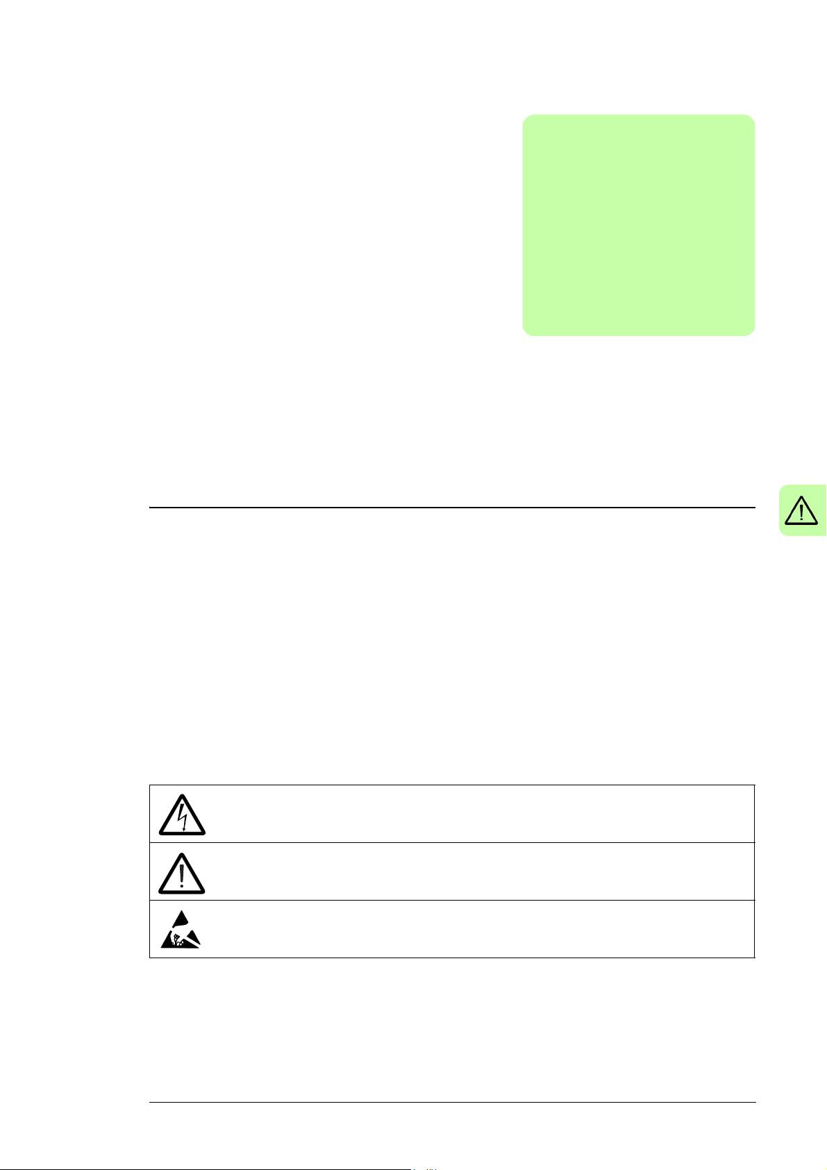
• Make sure that the module does not topple over when you move it on the floor:
Open the support legs by pressing each leg a little down (1, 2) and turning it aside.
Whenever possible secure the module also with chains.
• Do not tilt the drive module (A). It is heavy and its center of gravity is high. The
module overturns from a sideways tilt of 5 degrees. Do not leave the module
unattended on a sloping floor.
• Do not use the module installation ramp with plinth heights which exceed the
maximum height marked on the ramp. (The maximum plinth height is 50 mm
[1.97 in] when the telescopic ramp is fully retracted and 150 mm [5.91 in] when
the ramp is fully extended.)
• Attach the module installation ramp carefully.
Safety instructions 15
3AUA0000088632
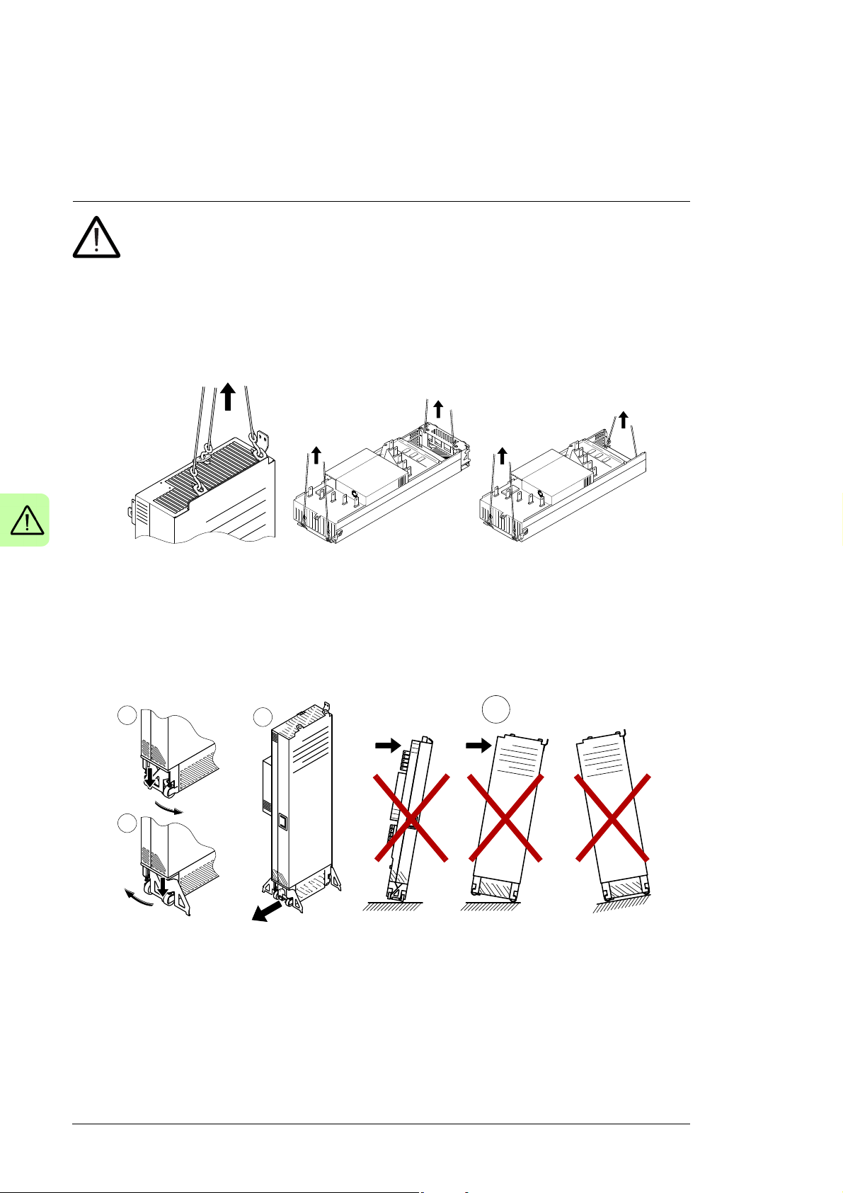
• To prevent the drive module from falling, attach its top lifting lugs with chains to the
cabinet frame before you push the module into the cabinet and pull it from the
cabinet. Work carefully preferably with help from another person as shown below.
Keep a constant pressure with one foot on the base of the module to prevent the
module from falling on its back
• Beware of hot surfaces. Some parts, such as heatsinks of power semiconductors,
remain hot for a while after disconnection of the electrical supply.
• Make sure that debris from borings and grindings does not enter the drive during the
installation. Electrically conductive debris inside the drive may cause damage or
malfunction.
• Make sure that there is sufficient cooling.
• Before you connect voltage to the drive, make sure that the cabinet doors are closed.
Keep the doors closed during the operation. Obey the panel builder’s instructions.
• Before you adjust the drive operation limits, make sure that the motor and all driven
equipment can operate throughout the set operation limits.
• Before you activate the automatic fault reset or automatic restart functions of the drive
control program, make sure that no dangerous situations can occur. These functions
reset the drive automatically and continue operation after a fault or supply break.
• The maximum number of drive power-ups is five in ten minutes. Too frequent power-
ups can damage the charging circuit of the DC capacitors.
• Make sure that any safety circuits (for example, emergency stop and Safe torque off)
are validated in start-up. See chapter Start-up for reference of the validation
instructions.
Note:
• If you select an external source for start command and it is on, the drive will start
immediately after fault reset unless you configure the drive for pulse start. See the
firmware manual.
• When the control location is not set to Local, the stop key on the control panel will not
stop the drive.

16 Safety instructions
Electrical safety in installation, start-up and maintenance
Precautions before electrical work
These warnings are for all personnel that do work on the drive, motor cable or motor.
WARNING! Obey these instructions. If you ignore them, injury or death, or
damage to the equipment can occur. If you are not a qualified electrician, do not
do installation or maintenance work. Go through these steps before you begin any
installation or maintenance work.
1. Clearly identify the work location.
2. Disconnect all possible voltage sources.
• Open the main disconnector of the drive.
• Open the disconnector of the supply transformer as the main disconnector of the
drive does not remove the voltage from the input busbars of the drive.
• Make sure that reconnection is not possible. Lock the disconnectors to open
position and attach a warning notice to them.
• Disconnect any external power sources from the control circuits before you do
work on the control cables.
• After you disconnect the drive, always wait for 5 minutes to let the intermediate
circuit capacitors discharge before you continue.
3. Protect any other energized parts in the work location against contact.
4. Take special precautions when close to bare conductors.
5. Measure that the installation is de-energized.
• Use a multimeter with an impedance of at least 1 Mohm.
• Make sure that the voltage between the drive module input power terminals
(L1/U1, L2/V1, L3/W1) and the grounding (PE) busbar is close to 0 V.
• Make sure that the voltage between the drive module UDC+ and UDC- terminals
and the grounding (PE) busbar is close to 0 V.
6. Install temporary grounding as required by the local regulations.
7. Ask for a permit to work from the person in control of the electrical installation work.
Safety instructions 17
Additional instructions and notes
WARNING! Obey these instructions. If you ignore them, injury or death, or
damage to the equipment can occur.
• If you are not a qualified electrician, do not do installation or maintenance work.
• Do not install a drive with EMC filter option +E200 or ARFI-10 on an ungrounded
power system or a high resistance-grounded (over 30 ohms) power system.
• Do not connect the drive to a voltage higher than what is on the type designation label.
If you do, the brake chopper starts to operate which causes the overheating of the
brake resistor (if present). Overvoltage can also cause the motor to rush to its
maximum speed.
• We do not recommend that you secure the cabinet by arc welding.
• Do not do insulation or voltage withstand tests on the drive or drive modules.
Note:
• The motor cable terminals of the drive are at a dangerous voltage when the input
power is on, regardless of whether the motor is running or not.
• The DC bus and brake resistor terminals (UDC+, UDC-, R+ and R-) are at a
dangerous voltage.
• External wiring can supply dangerous voltages to the terminals of relay outputs
(XRO1, XRO2 and XRO3).
• The Safe torque off function does not remove the voltage from the main and auxiliary
circuits. The function is not effective against deliberate sabotage or misuse.
WARNING! Use a grounding wrist band when you handle the printed circuit
boards. Do not touch the boards unnecessarily. The boards contain components
sensitive to electrostatic discharge.
WARNING! Obey these instructions. If you ignore them, equipment malfunction
and damage to the fiber optic cables can occur.
• Handle the fiber optic cables with care.
• When you unplug the cables, always hold the connector, not the cable itself.
• Do not touch the ends of the fibers with bare hands as the ends are extremely
sensitive to dirt.
• Do not bend the fiber optic cables too tightly. The minimum allowed bend radius is
35 mm (1.4 in).

18 Safety instructions
Grounding
These instructions are for all personnel who are responsible for the grounding of the drive.
WARNING! Obey these instructions. If you ignore them, injury or death, or
equipment malfunction can occur, and electromagnetic interference can increase.
• If you are not a qualified electrician, do not do grounding work.
• Always ground the drive, the motor and adjoining equipment. This is necessary for the
personnel safety. Proper grounding also reduces electromagnetic emission and
interference.
• Make sure that the conductivity of the grounding conductors is sufficient. See section
Selecting the power cables on page 71. Obey the local regulations.
• Connect the power cable shields to protective earth (PE) of the drive to make sure of
personnel safety.
• Make a 360° grounding of the power and control cable shields at the cable entries to
suppress electromagnetic disturbances.
• In a multiple-drive installation, connect each drive separately to the protective earth
(PE) busbar of the switch board or the transformer.
Note:
• You can use power cable shields as grounding conductors only when their conductivity
is sufficient.
• As the normal touch current of the drive is higher than 3.5 mA AC or 10 mA DC, you
must use a fixed protective earth connection. See standard EN 61800-5-1, 4.3.5.5.2.

Safety instructions 19
Additional instructions for permanent magnet motor drives
Safety in installation, start-up and maintenance
These are additional warnings concerning permanent magnet motor drives. The other
safety instructions in this chapter are also valid.
WARNING! Obey these instructions. If you ignore them, injury or death and
equipment malfunction can occur.
• Do not do work on the drive when the permanent magnet motor is rotating. A rotating
permanent magnet motor energizes the drive including its input power terminals.
Before installation, start-up and maintenance work on the drive:
• Stop the motor.
• Disconnect the motor from the drive with a safety switch or by other means.
• If you cannot disconnect the motor, make sure that the motor cannot rotate during
work. Make sure that no other system, like hydraulic crawling drives, can rotate the
motor directly or through any mechanical connection like felt, nip, rope, etc.
• Measure that the installation is de-energized.
• Use a multimeter with an impedance of at least 1 Mohm.
• Make sure that the voltage between the drive output terminals (T1/U2, T2/V2,
T3/W2) and the grounding (PE) busbar is close to 0 V.
• Make sure that the voltage between the drive input power terminals (L1/U1, L2/V1,
L3/W1) and the grounding (PE) busbar is close to 0 V.
• Make sure that the voltage between the drive module UDC+ and UDC- terminals
and the grounding (PE) busbar is close to 0 V.
• Install temporary grounding to the drive output terminals (T1/U2, T2/V2, T3/W2).
Connect the output terminals together as well as to the PE.
• Make sure that the operator cannot run the motor over the rated speed. Motor
overspeed causes overvoltage can damage or explode the capacitors in the
intermediate circuit of the drive.

20 Safety instructions

Introduction to the manual 21
2
Introduction to the manual
Contents of this chapter
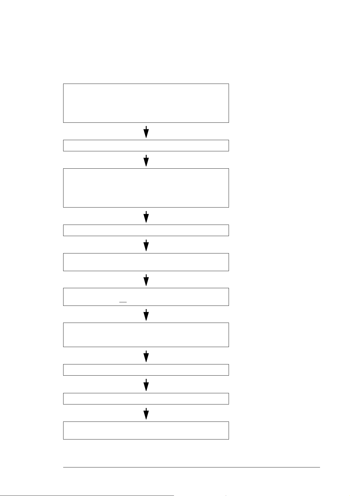
This chapter describes the manual. It contains a flowchart of steps in checking the
delivery, installing and starting up the drive. The flowchart refers to chapters/sections in
this manual and to other manuals.
Target audience
This manual is intended for people who plan the installation, install, start up, use and
service the drive. Read the manual before working on the drive. You are expected to know
the fundamentals of electricity, wiring, electrical components and electrical schematic
symbols.
The manual is written for readers worldwide. Both SI and imperial units are shown.
Contents of the manual
This manual contains the instructions and information for the basic drive configuration. The
chapters of the manual are briefly described below.
Safety instructions gives safety instructions for the installation, start-up, operation and
maintenance of the drive.
Introduction to the manual gives an introduction to this manual.
Operation principle and hardware description describes the operation principle and
construction of the drive.
Mechanical installation describes how to install the drive mechanically.
Guidelines for planning the electrical installation contains instructions for the motor and
cable selection, protections and cable routing.

22 Introduction to the manual
Electrical installation gives instructions on wiring the drive.
Control units of the drive contains the default I/O connection diagrams, descriptions of the
terminals and technical data for the control units of both the supply and inverter units.
Installation checklist contains a list for checking the mechanical and electrical installation
of the drive.
Start-up describes the start-up procedure of the drive.
Fault tracing describes the fault tracing possibilities of the drive.
Maintenance contains preventive maintenance instructions.
Technical data contains the technical specifications of the drive, eg. the ratings, sizes and
technical requirements, provisions for fulfilling the requirements for CE and other
markings.
Dimensions contains example dimension drawings of the drive.
Safe torque off function describes the Safe torque off function of the drive and gives
instructions on its implementation.
Resistor braking describes selection, protection and wiring of optional brake choppers and
resistors. The chapter also contains technical data.
Related manuals
See List of related manuals on the inside of the front cover.
Categorization by frame size and option code
Some instructions, technical data and dimension drawings which concern only certain
frame sizes are marked with the symbol of the frame size. The instructions, technical data
and dimension drawings which concern only certain drive.
Frame sizes are marked with the symbol of the frame size (R10 or R11). The frame size is
marked on the type designation label.
Introduction to the manual 23
Quick installation, commissioning and operation flowchart
Task See
Plan the electrical installation and acquire the accessories needed
(cables, fuses, etc.).
Check the ratings, required cooling air flow, input power connection,
compatibility of the motor, motor connection, and other technical
data.
Check the installation site. Ambient conditions (page 140)
Unpack and check the drive (only intact units may be started up).
Make sure that all necessary optional modules and equipment are
present and correct.
Mount the drive.
Route the cables. Routing the cables (page 85)
Check the insulation of the supply cable, the motor and the motor
cable.
Guidelines for planning the
electrical installation (page 73)
Technical data (page 133)
Mechanical installation (page 43)
If the drive has been nonoperational for more than one year,
the DC link capacitors need to be
reformed (page 129)
Checking the insulation of the
assembly (page 75)
If the drive is about to be connected to an IT (ungrounded) system,
check that the drive is not
Connect the power cables.
Connect the control cables.
Check the installation. Installation checklist (page 105)
Start the drive up. Start-up (page 107)
Operate the drive: start, stop, speed control etc. ACS880 quick start-up guide,
equipped with EMC filter +E200.
Checking the compatibility with IT
(ungrounded) systems (page 76)
Connecting the input power cables
(page 87), Connecting the control
cables (page 77),
firmware manual

24 Introduction to the manual
Terms and abbreviations
Term/
Abbreviation
BCU Drive control unit. The drive contains two BCU control units. One controls the supply unit,
Drive Frequency converter for controlling AC motors.
EMC Electromagnetic compatibility
EMI Electromagnetic interference
EMT Electrical metallic tubing
FAIO-01 Optional analog I/O extension module
FCAN-01 Optional FCAN-01 CANopen adapter module
FCNA-01 Optional ControlNet™ adapter module
FDCO-01 Optional DDCS communication module with two pairs of 10 Mbit/s DDCS channels
FDNA-01 Optional DeviceNet™ adapter module
FECA-01 Optional EtherCAT adapter module
FEN-01 Optional TTL incremental encoder interface module
FEN-11 Optional TTL absolute encoder interface module
FEN-21 Optional resolver interface module
FEN-31 Optional HTL incremental encoder interface module
FENA-11 Optional Ethernet adapter module for EtherNet/IP™, Modbus TCP and PROFINET IO
FENA-21 Optional Ethernet adapter module for EtherNet/IP™, Modbus TCP and PROFINET IO
FEPL-01 Optional Ethernet POWERLINK adapter module
FIO-01 Optional digital I/O extension module
FIO-11 Optional analog I/O extension module
FLON-01 Optional LonWorks® adapter module
FPBA-01 Optional PROFIBUS DP adapter module
Frame (size) Relates to the construction type of the component in question. For example, several drive
FSO-12,
FSO-21
IGBT Insulated gate bipolar transistor; a voltage-controlled semiconductor type widely used in
I/O Input/Output
Power module Supply module or inverter module. See also Frame (size).
RFI Radio-frequency interference
SAR Safe acceleration range
SBC Safe brake control
SLS Safely-limited speed without encoder
SS1 Safe stop 1
SSE Safe stop emergency
SSM Safe speed monitor without encoder
STO Safe torque off
Explanation
the other controls the inverter unit.
As standard, the external I/O control signals are connected to the control unit, or optional I/O
extensions mounted on it.
In this manual, the term refers to the ACS880-07XT as a whole.
protocols
protocols, 2-port
types with different power ratings may have the same basic construction, and a frame size is
used in reference to all those drive types.
To determine the frame size of a drive type, see the rating tables in chapter Te c hnica l data.
Optional functional safety modules
drives due to their easy controllability and high switching frequency.

Introduction to the manual 25
Safety data (SIL, PL)
Abbr. Reference Description
Cat. EN ISO 13849-1 Classification of the safety-related parts of a control system in respect
of their resistance to faults and their subsequent behavior in the fault
condition, and which is achieved by the structural arrangement of the
parts, fault detection and/or by their reliability. The categories are: B, 1,
2, 3 and 4.
CCF EN ISO 13849-1 Common cause failure (%)
DC EN ISO 13849-1 Diagnostic coverage
FIT IEC 61508 Failure in time: 1E-9 hours
HFT IEC 61508 Hardware fault tolerance
MTTF
PFD IEC 61508 Probability of failure on demand
PFH
D
PL EN ISO 13849-1 Performance level. Levels a…e correspond to SIL
SC IEC 61508 Systematic capability
SFF IEC 61508 Safe failure fraction (%)
SIL IEC 61508 Safety integrity level (1…3)
SILCL IEC/EN 62061 Maximum SIL (level 1…3) that can be claimed for a safety function or
SS1 IEC/EN 61800-5-2 Safe stop 1
STO IEC/EN 61800-5-2 Safe torque off
T1 IEC 61508 Proof test interval. T1 is a parameter used to define the probabilistic
EN ISO 13849-1 Mean time to dangerous failure: (The total number of life units) / (the
d
IEC 61508 Probability of dangerous failures per hour
number of dangerous, undetected failures) during a particular
measurement interval under stated conditions
subsystem
failure rate (PFH or PFD) for the safety function or subsystem.
Performing a proof test at a maximum interval of T1 is required to keep
the SIL capability valid. The same interval must be followed to keep the
PL capability (EN ISO 13849) valid. Note that any T1 values given
cannot be regarded as a guarantee or warranty.
See also section Maintenance (page 258).

26 Introduction to the manual

Operation principle and hardware description 27
3
Operation principle and hardware description
Contents of this chapter
This chapter briefly describes the operation principle and construction of the drive.
Product overview
The ACS880-07XT is an air-cooled cabinet-installed drive for controlling asynchronous AC
induction motors, permanent magnet synchronous motors and AC induction servomotors.
The drive consists of two drive modules (ACS880-04 +P943) and a separate control unit.
28 Operation principle and hardware description
L1/U1
L2/V1
L3/W1
T1/U2
T2/V2
T3/W2
R-
R+
421
UDC-
UDC+
PE
5
ACS880-04 +P943
3
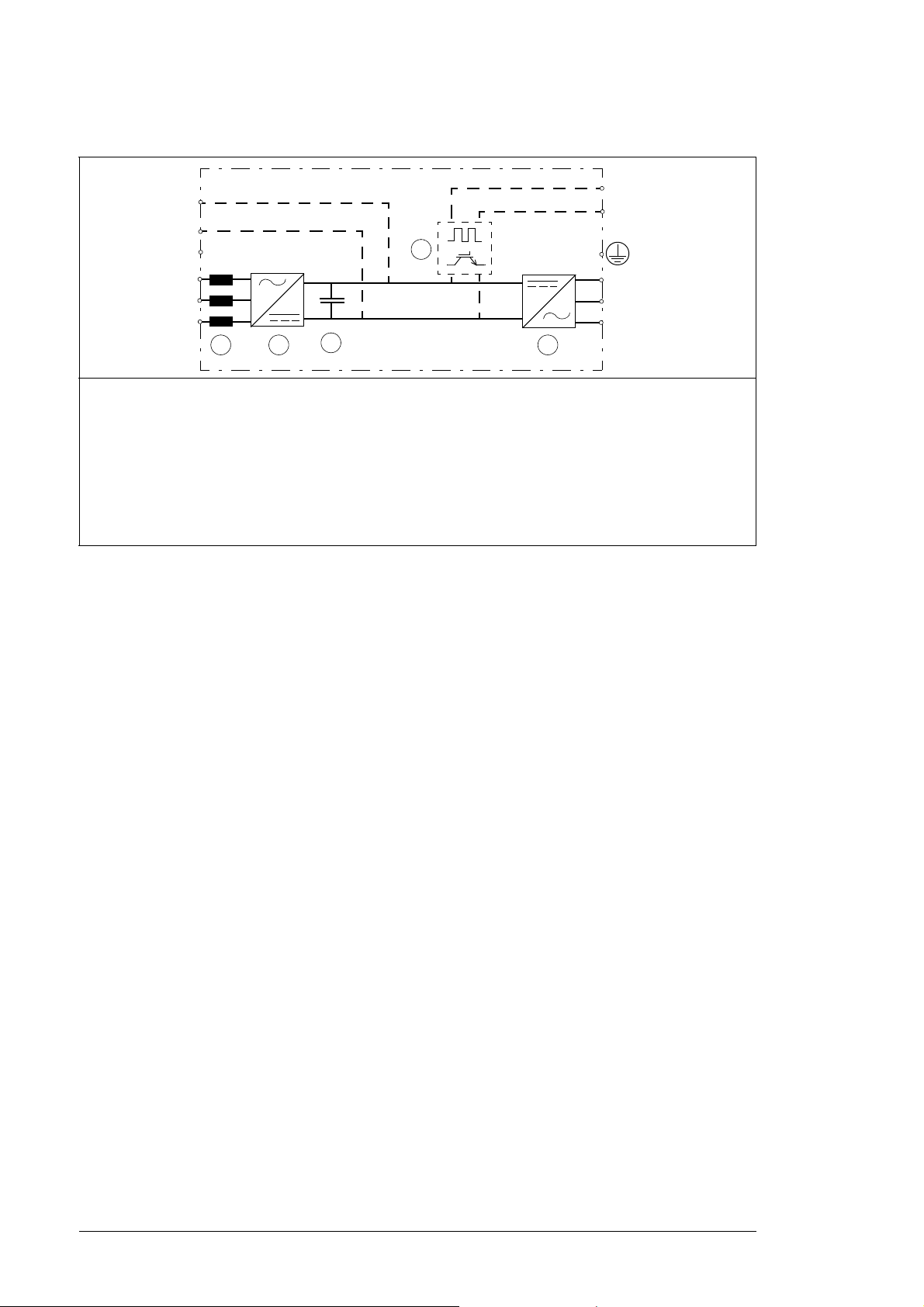
Overview circuit diagram of the drive
1 AC choke
2 Rectifier. Converts alternating current and voltage to direct current and voltage.
3 DC link. DC circuit between rectifier and inverter
4 Inverter. Converts direct current and voltage to alternating current and voltage.
5 Brake chopper (option +D150). Conducts the surplus energy from the intermediate circuit of the
drive to the brake resistor when necessary. The chopper operates when the DC link voltage
exceeds a certain maximum limit. The voltage rise is typically caused by deceleration (braking) of a
high inertia motor.
Operation principle and hardware description 29
1 2
3
1 2
3
6-pulse connection
12-pulse connection
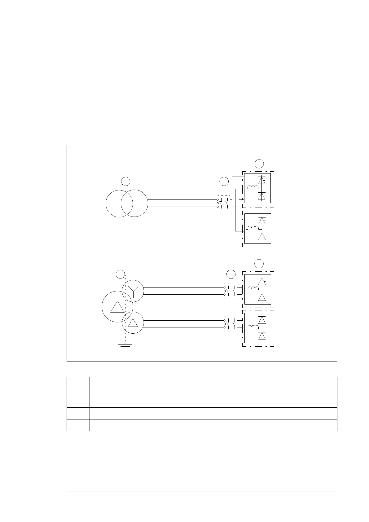
12-pulse connection (option +A004)
The figure below illustrates the difference between 6-pulse and 12-pulse AC supply
connections. 6-pulse connection is standard. If the drive has an even number of supply
modules, you can order it as a 12-pulse version (option +A004).
12-pulse supply connection eliminates the fifth and seventh harmonics, which remarkably
reduces the harmonic distortion of the line current and the conducted emissions.
12-pulse connection requires a three-winding transformer, or two separate transformers.
There is a 30-degree phase shift between the two 6-pulse supply lines, which are
connected to different supply modules through electrically separate switching equipment.
No. Description
1. Supply transformer. See section Electrical power network specification (page 139) for transformer
requirements.
2. Switching equipment
3. Diode supply modules
30 Operation principle and hardware description
A
C D
1
3
2
B
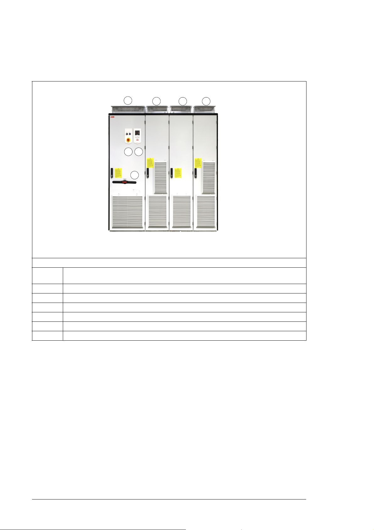
Cabinet line-up and layout examples
Example(Frame R11)
Cabinet line-up example
A Incoming and Auxiliary control cubicle (ICU). Contains control electronics, customer I/O
connections, the power input cable terminals and switchgear.
B Module cubicle. Contains the R11 module.
C Output cubicle. Contains the du/dt (option) and output ternimals for motor.
D Module cubicle. Contains the R11 module.
1 Main switch-disconnector (Q1.1)
2 Door switches and lights
3 Drive control panel
 Loading...