

ABB machinery drives
Hardware manual
ACS850-04 drive modules (160 to 560 kW, 200 to 700 hp)

List of related manuals
ACS850-04 manuals
Drive hardware manuals and guides Code (English)
ACS850-04 drive modules (160 to 560 kW, 200 to 700 hp) hardware manual 3AUA0000081249
Safe torque off function for ACSM1, ACS850 and ACQ810 drives application
guide
Drive firmware manuals and guides
ACS850 standard control program quick start-up guide 3AUA0000045498
ACS850 standard control program firmware manual 3AUA0000045497
ACS850 crane control program supplement (to std ctrl prg) 3AUA0000081708
ACS850-04 drives with SynRM motors (option +N7502) supplement 3AUA0000123521
Option manuals and guides
ACS-CP-U Control Panel IP54 Mounting Platform Kit (+J410) Installation
Guide
ACS850 Common DC configuration for ACS850-04 drives application guide 3AUA0000073108
ATEX-certified Safe disconnection function for ACS850 drives (+Q971)
application guide
Application programming for ACS850 and ACQ810 drives application guide 3AUA0000078664
Manuals and quick guides for I/O extension modules, fieldbus adapters, etc.
You can find manuals and other product documents in PDF format on the Internet. See section
Document library on the Internet on the inside of the back cover. For manuals not available in the
Document library, contact your local ABB representative.
3AFE68929814
3AUA0000049072
3AUA0000074343

ACS850-04 drive modules
160 to 560 kW (200 to 700 hp)
Hardware manual
2013 ABB Oy. All Rights Reserved.
3AUA0000081249 Rev C
EN
EFFECTIVE: 2013-04-11


Table of contents
List of related manuals . . . . . . . . . . . . . . . . . . . . . . . . . . . . . . . . . . . . . . . . . . . . . . . . . . . . . . . . . . . 2
Table of contents
Safety instructions
What this chapter contains . . . . . . . . . . . . . . . . . . . . . . . . . . . . . . . . . . . . . . . . . . . . . . . . . . . . . . . 13
Use of warnings . . . . . . . . . . . . . . . . . . . . . . . . . . . . . . . . . . . . . . . . . . . . . . . . . . . . . . . . . . . . . . . . 13
Safety in installation and maintenance . . . . . . . . . . . . . . . . . . . . . . . . . . . . . . . . . . . . . . . . . . . . . . 14
Electrical safety . . . . . . . . . . . . . . . . . . . . . . . . . . . . . . . . . . . . . . . . . . . . . . . . . . . . . . . . . . . 14
Grounding . . . . . . . . . . . . . . . . . . . . . . . . . . . . . . . . . . . . . . . . . . . . . . . . . . . . . . . . . . . 15
Permanent magnet motor drives . . . . . . . . . . . . . . . . . . . . . . . . . . . . . . . . . . . . . . . . . 16
General safety . . . . . . . . . . . . . . . . . . . . . . . . . . . . . . . . . . . . . . . . . . . . . . . . . . . . . . . . . . . . 17
Fiber optic cables . . . . . . . . . . . . . . . . . . . . . . . . . . . . . . . . . . . . . . . . . . . . . . . . . . . . . 18
Printed circuit boards . . . . . . . . . . . . . . . . . . . . . . . . . . . . . . . . . . . . . . . . . . . . . . . . . . 19
Safe start-up and operation . . . . . . . . . . . . . . . . . . . . . . . . . . . . . . . . . . . . . . . . . . . . . . . . . . . . . . . 19
General safety . . . . . . . . . . . . . . . . . . . . . . . . . . . . . . . . . . . . . . . . . . . . . . . . . . . . . . . . . . . . 19
Permanent magnet motor drives . . . . . . . . . . . . . . . . . . . . . . . . . . . . . . . . . . . . . . . . . . . . . . 19
5
Introduction to the manual
What this chapter contains . . . . . . . . . . . . . . . . . . . . . . . . . . . . . . . . . . . . . . . . . . . . . . . . . . . . . . . 21
Target audience . . . . . . . . . . . . . . . . . . . . . . . . . . . . . . . . . . . . . . . . . . . . . . . . . . . . . . . . . . . . . . . 21
Contents of the manual . . . . . . . . . . . . . . . . . . . . . . . . . . . . . . . . . . . . . . . . . . . . . . . . . . . . . . . . . . 21
Categorization by frame size and option code . . . . . . . . . . . . . . . . . . . . . . . . . . . . . . . . . . . . . . . . 22
Quick installation, commissioning and operating flowchart . . . . . . . . . . . . . . . . . . . . . . . . . . . . . . . 22
Terms and abbreviations . . . . . . . . . . . . . . . . . . . . . . . . . . . . . . . . . . . . . . . . . . . . . . . . . . . . . . . . . 24
Operation principle and hardware description
What this chapter contains . . . . . . . . . . . . . . . . . . . . . . . . . . . . . . . . . . . . . . . . . . . . . . . . . . . . . . . 27
Product overview . . . . . . . . . . . . . . . . . . . . . . . . . . . . . . . . . . . . . . . . . . . . . . . . . . . . . . . . . . . . . . . 27
Layout . . . . . . . . . . . . . . . . . . . . . . . . . . . . . . . . . . . . . . . . . . . . . . . . . . . . . . . . . . . . . . . . . . 28
Power connections and control interfaces . . . . . . . . . . . . . . . . . . . . . . . . . . . . . . . . . . . . . . . 32
External control unit connection cables . . . . . . . . . . . . . . . . . . . . . . . . . . . . . . . . . . . . . . . . . 33
Type designation label . . . . . . . . . . . . . . . . . . . . . . . . . . . . . . . . . . . . . . . . . . . . . . . . . . . . . . . . . . 34
Type designation key . . . . . . . . . . . . . . . . . . . . . . . . . . . . . . . . . . . . . . . . . . . . . . . . . . . . . . . . . . . 35
Planning the cabinet installation
What this chapter contains . . . . . . . . . . . . . . . . . . . . . . . . . . . . . . . . . . . . . . . . . . . . . . . . . . . . . . . 37
Limitation of liability . . . . . . . . . . . . . . . . . . . . . . . . . . . . . . . . . . . . . . . . . . . . . . . . . . . . . . . . . . . . . 37
Basic requirements for the cabinet . . . . . . . . . . . . . . . . . . . . . . . . . . . . . . . . . . . . . . . . . . . . . . . . . 37
Planning the layout of the cabinet . . . . . . . . . . . . . . . . . . . . . . . . . . . . . . . . . . . . . . . . . . . . . . . . . . 37
Table of contents

6
Layout examples, door closed . . . . . . . . . . . . . . . . . . . . . . . . . . . . . . . . . . . . . . . . . . . . . . . .38
Layout example, door open . . . . . . . . . . . . . . . . . . . . . . . . . . . . . . . . . . . . . . . . . . . . . . . . . . .38
Arranging the grounding inside the cabinet . . . . . . . . . . . . . . . . . . . . . . . . . . . . . . . . . . . . . . . . . . .40
Selecting the busbar material and preparation of the joints . . . . . . . . . . . . . . . . . . . . . . . . . . . . . . .40
Tightening torques . . . . . . . . . . . . . . . . . . . . . . . . . . . . . . . . . . . . . . . . . . . . . . . . . . . . . . . . . . . . . .40
Planning the fastening of the cabinet . . . . . . . . . . . . . . . . . . . . . . . . . . . . . . . . . . . . . . . . . . . . . . . .40
Planning the cabinet placement on a cable channel . . . . . . . . . . . . . . . . . . . . . . . . . . . . . . . . . . . .41
Planning the electromagnetic compatibility (EMC) of the cabinet . . . . . . . . . . . . . . . . . . . . . . . . . .41
Planning the grounding of the cable shields at the cabinet lead-through . . . . . . . . . . . . . . . . . . . . .43
Planning the cooling . . . . . . . . . . . . . . . . . . . . . . . . . . . . . . . . . . . . . . . . . . . . . . . . . . . . . . . . . . . . .43
Preventing the recirculation of hot air . . . . . . . . . . . . . . . . . . . . . . . . . . . . . . . . . . . . . . . . . . . . . . . .45
Required free space . . . . . . . . . . . . . . . . . . . . . . . . . . . . . . . . . . . . . . . . . . . . . . . . . . . . . . . . . . . . .47
Free space at the top of the drive module . . . . . . . . . . . . . . . . . . . . . . . . . . . . . . . . . . . . . . . .47
Free space around the drive module . . . . . . . . . . . . . . . . . . . . . . . . . . . . . . . . . . . . . . . . . . .47
Other installation positions . . . . . . . . . . . . . . . . . . . . . . . . . . . . . . . . . . . . . . . . . . . . . . . . . . . . . . . .47
Planning the placement of the control panel . . . . . . . . . . . . . . . . . . . . . . . . . . . . . . . . . . . . . . . . . .48
Planning the use of the cubicle heaters . . . . . . . . . . . . . . . . . . . . . . . . . . . . . . . . . . . . . . . . . . . . . .48
Planning the electrical installation
What this chapter contains . . . . . . . . . . . . . . . . . . . . . . . . . . . . . . . . . . . . . . . . . . . . . . . . . . . . . . . .49
Selecting the supply disconnecting device . . . . . . . . . . . . . . . . . . . . . . . . . . . . . . . . . . . . . . . . . . . .49
European Union . . . . . . . . . . . . . . . . . . . . . . . . . . . . . . . . . . . . . . . . . . . . . . . . . . . . . . . . . . .49
Other regions . . . . . . . . . . . . . . . . . . . . . . . . . . . . . . . . . . . . . . . . . . . . . . . . . . . . . . . . . . . . .49
Selecting and dimensioning the main contactor . . . . . . . . . . . . . . . . . . . . . . . . . . . . . . . . . . . . . . . .49
Protecting the motor insulation and bearings . . . . . . . . . . . . . . . . . . . . . . . . . . . . . . . . . . . . . . . . . .50
Checking the compatibility of the motor and drive . . . . . . . . . . . . . . . . . . . . . . . . . . . . . . . . . . . . . .50
Requirements table . . . . . . . . . . . . . . . . . . . . . . . . . . . . . . . . . . . . . . . . . . . . . . . . . . . . . . . . .51
Additional requirements for explosion-safe (EX) motors . . . . . . . . . . . . . . . . . . . . . . . .53
Additional requirements for HXR and AMA motors . . . . . . . . . . . . . . . . . . . . . . . . . . . .53
Additional requirements for ABB motors of types other than M2_, M3_, M4_, HX_
and AM_ . . . . . . . . . . . . . . . . . . . . . . . . . . . . . . . . . . . . . . . . . . . . . . . . . . . . . . . . . . . .53
Additional requirements for the braking applications . . . . . . . . . . . . . . . . . . . . . . . . . . .53
Additional requirements for ABB high-output motors and IP23 motors . . . . . . . . . . . . .53
Additional requirements for non-ABB high-output and IP23 motors . . . . . . . . . . . . . . .54
Additional data for calculating the rise time and the peak line-to-line voltage . . . . . . . .55
Additional note for sine filters . . . . . . . . . . . . . . . . . . . . . . . . . . . . . . . . . . . . . . . . . . . . .55
Additional note common mode filters . . . . . . . . . . . . . . . . . . . . . . . . . . . . . . . . . . . . . . .55
Selecting the power cables . . . . . . . . . . . . . . . . . . . . . . . . . . . . . . . . . . . . . . . . . . . . . . . . . . . . . . .56
General rules . . . . . . . . . . . . . . . . . . . . . . . . . . . . . . . . . . . . . . . . . . . . . . . . . . . . . . . . . . . . . .56
Typical power cable sizes . . . . . . . . . . . . . . . . . . . . . . . . . . . . . . . . . . . . . . . . . . . . . . . . . . . .57
Alternative power cable types . . . . . . . . . . . . . . . . . . . . . . . . . . . . . . . . . . . . . . . . . . . . . . . . .58
Motor cable shield . . . . . . . . . . . . . . . . . . . . . . . . . . . . . . . . . . . . . . . . . . . . . . . . . . . . . . . . . .58
Additional US requirements . . . . . . . . . . . . . . . . . . . . . . . . . . . . . . . . . . . . . . . . . . . . . . . . . .59
Conduit . . . . . . . . . . . . . . . . . . . . . . . . . . . . . . . . . . . . . . . . . . . . . . . . . . . . . . . . . . . . .59
Armored cable / shielded power cable . . . . . . . . . . . . . . . . . . . . . . . . . . . . . . . . . . . . . .59
Selecting the control cables . . . . . . . . . . . . . . . . . . . . . . . . . . . . . . . . . . . . . . . . . . . . . . . . . . . . . . .59
Shielding . . . . . . . . . . . . . . . . . . . . . . . . . . . . . . . . . . . . . . . . . . . . . . . . . . . . . . . . . . . . . . . . .59
Signals in separate cables . . . . . . . . . . . . . . . . . . . . . . . . . . . . . . . . . . . . . . . . . . . . . . . . . . .60
Signals allowed to be run in the same cable . . . . . . . . . . . . . . . . . . . . . . . . . . . . . . . . . . . . . .60
Table of contents

Relay cable type . . . . . . . . . . . . . . . . . . . . . . . . . . . . . . . . . . . . . . . . . . . . . . . . . . . . . . . . . . 60
Control panel cable length and type . . . . . . . . . . . . . . . . . . . . . . . . . . . . . . . . . . . . . . . . . . . 60
Routing the cables . . . . . . . . . . . . . . . . . . . . . . . . . . . . . . . . . . . . . . . . . . . . . . . . . . . . . . . . . . . . . . 60
Separate control cable ducts . . . . . . . . . . . . . . . . . . . . . . . . . . . . . . . . . . . . . . . . . . . . . . . . . 61
Continuous motor cable shield or enclosure for equipment in the motor cable . . . . . . . . . . . 62
Implementing thermal overload and short-circuit protection . . . . . . . . . . . . . . . . . . . . . . . . . . . . . . 62
Protecting the drive and input power cable in short-circuits . . . . . . . . . . . . . . . . . . . . . . . . . . 62
Protecting the motor and motor cable in short-circuits . . . . . . . . . . . . . . . . . . . . . . . . . . . . . . 62
Protecting the drive and the input power and motor cables against thermal overload . . . . . 63
Protecting the motor against thermal overload . . . . . . . . . . . . . . . . . . . . . . . . . . . . . . . . . . . 63
Protecting the drive against ground faults . . . . . . . . . . . . . . . . . . . . . . . . . . . . . . . . . . . . . . . . . . . . 63
Residual current device compatibility . . . . . . . . . . . . . . . . . . . . . . . . . . . . . . . . . . . . . . . . . . . 63
Implementing the Emergency stop function . . . . . . . . . . . . . . . . . . . . . . . . . . . . . . . . . . . . . . . . . . 64
Implementing the Safe torque off function . . . . . . . . . . . . . . . . . . . . . . . . . . . . . . . . . . . . . . . . . . . . 64
Implementing the ATEX-certified Safe motor disconnection function (option +Q971) . . . . . . . . . . 64
Implementing the Power loss ride-through function . . . . . . . . . . . . . . . . . . . . . . . . . . . . . . . . . . . . 64
Using power factor compensation capacitors with the drive . . . . . . . . . . . . . . . . . . . . . . . . . . . . . . 64
Implementing a safety switch between the drive and motor . . . . . . . . . . . . . . . . . . . . . . . . . . . . . . 65
Using a contactor between the drive and the motor . . . . . . . . . . . . . . . . . . . . . . . . . . . . . . . . . . . . 65
Implementing a bypass connection . . . . . . . . . . . . . . . . . . . . . . . . . . . . . . . . . . . . . . . . . . . . . . . . . 66
Example bypass connection . . . . . . . . . . . . . . . . . . . . . . . . . . . . . . . . . . . . . . . . . . . . . . . . . 66
Switching the motor power supply from drive to direct-on-line . . . . . . . . . . . . . . . . . . . 67
Switching the motor power supply from direct-on-line to drive . . . . . . . . . . . . . . . . . . . 67
Protecting the contacts of relay outputs . . . . . . . . . . . . . . . . . . . . . . . . . . . . . . . . . . . . . . . . . . . . . 67
Connecting a motor temperature sensor to the drive I/O . . . . . . . . . . . . . . . . . . . . . . . . . . . . . . . . 68
Example circuit diagram . . . . . . . . . . . . . . . . . . . . . . . . . . . . . . . . . . . . . . . . . . . . . . . . . . . . . . . . . 68
7
Installation
What this chapter contains . . . . . . . . . . . . . . . . . . . . . . . . . . . . . . . . . . . . . . . . . . . . . . . . . . . . . . . 69
Safety . . . . . . . . . . . . . . . . . . . . . . . . . . . . . . . . . . . . . . . . . . . . . . . . . . . . . . . . . . . . . . . . . . . . . . . 73
Checking the installation site . . . . . . . . . . . . . . . . . . . . . . . . . . . . . . . . . . . . . . . . . . . . . . . . . . . . . . 73
Required tools . . . . . . . . . . . . . . . . . . . . . . . . . . . . . . . . . . . . . . . . . . . . . . . . . . . . . . . . . . . . . . . . . 73
Moving and unpacking the unit . . . . . . . . . . . . . . . . . . . . . . . . . . . . . . . . . . . . . . . . . . . . . . . . . . . . 74
Checking the delivery . . . . . . . . . . . . . . . . . . . . . . . . . . . . . . . . . . . . . . . . . . . . . . . . . . . . . . . . . . . 76
Checking the insulation of the assembly . . . . . . . . . . . . . . . . . . . . . . . . . . . . . . . . . . . . . . . . . . . . . 76
Drive . . . . . . . . . . . . . . . . . . . . . . . . . . . . . . . . . . . . . . . . . . . . . . . . . . . . . . . . . . . . . . . . . . . . 76
Input cable . . . . . . . . . . . . . . . . . . . . . . . . . . . . . . . . . . . . . . . . . . . . . . . . . . . . . . . . . . . . . . . 76
Motor and motor cable . . . . . . . . . . . . . . . . . . . . . . . . . . . . . . . . . . . . . . . . . . . . . . . . . . . . . . 77
Brake resistor and resistor cable . . . . . . . . . . . . . . . . . . . . . . . . . . . . . . . . . . . . . . . . . . . . . . 77
Overall flowchart of the installation process . . . . . . . . . . . . . . . . . . . . . . . . . . . . . . . . . . . . . . . . . . 78
Installing the mechanical accessories into the cabinet . . . . . . . . . . . . . . . . . . . . . . . . . . . . . . . . . . 79
Assembly drawing (frame G1) . . . . . . . . . . . . . . . . . . . . . . . . . . . . . . . . . . . . . . . . . . . . . . . . 81
Assembly drawing (frame G2) . . . . . . . . . . . . . . . . . . . . . . . . . . . . . . . . . . . . . . . . . . . . . . . . 82
Assembly drawing (air baffles) . . . . . . . . . . . . . . . . . . . . . . . . . . . . . . . . . . . . . . . . . . . . . . . . 83
Connecting the power cables . . . . . . . . . . . . . . . . . . . . . . . . . . . . . . . . . . . . . . . . . . . . . . . . . . . . . 84
Connection diagram . . . . . . . . . . . . . . . . . . . . . . . . . . . . . . . . . . . . . . . . . . . . . . . . . . . . . . . . 84
Power cable connection procedure . . . . . . . . . . . . . . . . . . . . . . . . . . . . . . . . . . . . . . . . . . . . 86
DC connection . . . . . . . . . . . . . . . . . . . . . . . . . . . . . . . . . . . . . . . . . . . . . . . . . . . . . . . . . . . . 88
Mounting the drive module into the cabinet . . . . . . . . . . . . . . . . . . . . . . . . . . . . . . . . . . . . . . . . . . . 89
Table of contents

8
Mounting procedure . . . . . . . . . . . . . . . . . . . . . . . . . . . . . . . . . . . . . . . . . . . . . . . . . . . . . . . .90
Assembly drawing of installing the drive module to the cabinet (frame G1) . . . . . . . . . . . . . .93
Assembly drawing of installing the drive module to the cabinet (frame G2) . . . . . . . . . . . . . .94
Removing the protective covering from the module air outlet . . . . . . . . . . . . . . . . . . . . . . . . .95
Connecting the control cables . . . . . . . . . . . . . . . . . . . . . . . . . . . . . . . . . . . . . . . . . . . . . . . . . . . . .95
Flowchart of the control cable installation process (external control unit) . . . . . . . . . . . . . . . .95
Flowchart of the control cable installation process (internal control unit, option +P905) . . . . .95
Removing the cover assembly of the external control unit . . . . . . . . . . . . . . . . . . . . . . . . . . .96
Fastening the control cable clamp plate . . . . . . . . . . . . . . . . . . . . . . . . . . . . . . . . . . . . . . . . .97
Connecting the external control unit to the drive module . . . . . . . . . . . . . . . . . . . . . . . . . . . .97
Mounting the external control unit . . . . . . . . . . . . . . . . . . . . . . . . . . . . . . . . . . . . . . . . . . . . . .99
Mounting the external control unit to wall . . . . . . . . . . . . . . . . . . . . . . . . . . . . . . . . . . .99
Mounting the external control unit vertically on a DIN rail . . . . . . . . . . . . . . . . . . . . . .100
Mounting the control unit horizontally on a DIN rail . . . . . . . . . . . . . . . . . . . . . . . . . . .100
Installing optional modules . . . . . . . . . . . . . . . . . . . . . . . . . . . . . . . . . . . . . . . . . . . . . . . . . .101
Mechanical installation . . . . . . . . . . . . . . . . . . . . . . . . . . . . . . . . . . . . . . . . . . . . . . . . .101
Wiring the modules . . . . . . . . . . . . . . . . . . . . . . . . . . . . . . . . . . . . . . . . . . . . . . . . . . .101
Connecting the control cables to the terminals of the control unit . . . . . . . . . . . . . . . . . . . . .102
Default I/O connection diagram . . . . . . . . . . . . . . . . . . . . . . . . . . . . . . . . . . . . . . . . . . . . . . .104
Jumpers . . . . . . . . . . . . . . . . . . . . . . . . . . . . . . . . . . . . . . . . . . . . . . . . . . . . . . . . . . . .105
External power supply for the JCU control unit (XPOW) . . . . . . . . . . . . . . . . . . . . . . .106
DI6 (XDI:6) as a thermistor input . . . . . . . . . . . . . . . . . . . . . . . . . . . . . . . . . . . . . . . . .106
Drive-to-drive link (XD2D) . . . . . . . . . . . . . . . . . . . . . . . . . . . . . . . . . . . . . . . . . . . . . .107
Safe torque off (XSTO) . . . . . . . . . . . . . . . . . . . . . . . . . . . . . . . . . . . . . . . . . . . . . . . .108
Control cable connection procedure of units with internal control unit (option +P905) . . . . . . . . . .108
Connecting a PC . . . . . . . . . . . . . . . . . . . . . . . . . . . . . . . . . . . . . . . . . . . . . . . . . . . . . . . . . . . . . .108
Installation checklist
What this chapter contains . . . . . . . . . . . . . . . . . . . . . . . . . . . . . . . . . . . . . . . . . . . . . . . . . . . . . . .109
Installation checklist . . . . . . . . . . . . . . . . . . . . . . . . . . . . . . . . . . . . . . . . . . . . . . . . . . . . . . . . . . . .109
Start-up
What this chapter contains . . . . . . . . . . . . . . . . . . . . . . . . . . . . . . . . . . . . . . . . . . . . . . . . . . . . . . .113
Start-up procedure . . . . . . . . . . . . . . . . . . . . . . . . . . . . . . . . . . . . . . . . . . . . . . . . . . . . . . . . . . . . .113
Fault tracing
What this chapter contains . . . . . . . . . . . . . . . . . . . . . . . . . . . . . . . . . . . . . . . . . . . . . . . . . . . . . . .115
LEDs . . . . . . . . . . . . . . . . . . . . . . . . . . . . . . . . . . . . . . . . . . . . . . . . . . . . . . . . . . . . . . . . . . . . . . . .115
Warning and fault messages . . . . . . . . . . . . . . . . . . . . . . . . . . . . . . . . . . . . . . . . . . . . . . . . . . . . .115
Maintenance
What this chapter contains . . . . . . . . . . . . . . . . . . . . . . . . . . . . . . . . . . . . . . . . . . . . . . . . . . . . . . .117
Applicability . . . . . . . . . . . . . . . . . . . . . . . . . . . . . . . . . . . . . . . . . . . . . . . . . . . . . . . . . . . . . . . . . .117
Maintenance intervals . . . . . . . . . . . . . . . . . . . . . . . . . . . . . . . . . . . . . . . . . . . . . . . . . . . . . . . . . .117
Cabinet . . . . . . . . . . . . . . . . . . . . . . . . . . . . . . . . . . . . . . . . . . . . . . . . . . . . . . . . . . . . . . . . . . . . . .118
Table of contents

Cleaning the interior of the cabinet . . . . . . . . . . . . . . . . . . . . . . . . . . . . . . . . . . . . . . . . . . . 118
Heatsink . . . . . . . . . . . . . . . . . . . . . . . . . . . . . . . . . . . . . . . . . . . . . . . . . . . . . . . . . . . . . . . . . . . . 119
Cleaning the interior of the heatsink . . . . . . . . . . . . . . . . . . . . . . . . . . . . . . . . . . . . . . . . . . 119
Fans . . . . . . . . . . . . . . . . . . . . . . . . . . . . . . . . . . . . . . . . . . . . . . . . . . . . . . . . . . . . . . . . . . . . . . . 120
Replacing the circuit board compartment cooling fan . . . . . . . . . . . . . . . . . . . . . . . . . . . . . 120
Replacing the main cooling fans . . . . . . . . . . . . . . . . . . . . . . . . . . . . . . . . . . . . . . . . . . . . . 121
Replacing the drive module . . . . . . . . . . . . . . . . . . . . . . . . . . . . . . . . . . . . . . . . . . . . . . . . . . . . . . 122
Capacitors . . . . . . . . . . . . . . . . . . . . . . . . . . . . . . . . . . . . . . . . . . . . . . . . . . . . . . . . . . . . . . . . . . . 124
Reforming the capacitors . . . . . . . . . . . . . . . . . . . . . . . . . . . . . . . . . . . . . . . . . . . . . . . . . . . 124
Memory unit . . . . . . . . . . . . . . . . . . . . . . . . . . . . . . . . . . . . . . . . . . . . . . . . . . . . . . . . . . . . . . . . . . 124
Technical data
What this chapter contains . . . . . . . . . . . . . . . . . . . . . . . . . . . . . . . . . . . . . . . . . . . . . . . . . . . . . . 125
Ratings . . . . . . . . . . . . . . . . . . . . . . . . . . . . . . . . . . . . . . . . . . . . . . . . . . . . . . . . . . . . . . . . . . . . . 125
Derating . . . . . . . . . . . . . . . . . . . . . . . . . . . . . . . . . . . . . . . . . . . . . . . . . . . . . . . . . . . . . . . . 126
Ambient temperature derating . . . . . . . . . . . . . . . . . . . . . . . . . . . . . . . . . . . . . . . . . . 126
Altitude derating . . . . . . . . . . . . . . . . . . . . . . . . . . . . . . . . . . . . . . . . . . . . . . . . . . . . . 126
Fuses (IEC) . . . . . . . . . . . . . . . . . . . . . . . . . . . . . . . . . . . . . . . . . . . . . . . . . . . . . . . . . . . . . . . . . . 127
Ultrarapid (aR) fuses . . . . . . . . . . . . . . . . . . . . . . . . . . . . . . . . . . . . . . . . . . . . . . . . . . 127
aR fuses with flush end contact . . . . . . . . . . . . . . . . . . . . . . . . . . . . . . . . . . . . . . . . . 127
Fuses (UL) . . . . . . . . . . . . . . . . . . . . . . . . . . . . . . . . . . . . . . . . . . . . . . . . . . . . . . . . . . . . . . . . . . . 127
UL recognised Class T / Class L fuses . . . . . . . . . . . . . . . . . . . . . . . . . . . . . . . . . . . . 127
Dimensions, weights and free space requirements . . . . . . . . . . . . . . . . . . . . . . . . . . . . . . . . . . . . 128
Losses, cooling data and noise . . . . . . . . . . . . . . . . . . . . . . . . . . . . . . . . . . . . . . . . . . . . . . . . . . . 129
Terminal and lead-through data for the power cables . . . . . . . . . . . . . . . . . . . . . . . . . . . . . . . . . . 129
Units with optional common mode filter (+E208) . . . . . . . . . . . . . . . . . . . . . . . . . . . . . . . . . 129
Units with optional cabling panels (+H381 or +H383) . . . . . . . . . . . . . . . . . . . . . . . . . . . . . 129
Units without optional cabling panels (no +H381 or +H383) . . . . . . . . . . . . . . . . . . . . . . . . 130
Terminal data for the control cables . . . . . . . . . . . . . . . . . . . . . . . . . . . . . . . . . . . . . . . . . . . . . . . 130
Electrical power network specification . . . . . . . . . . . . . . . . . . . . . . . . . . . . . . . . . . . . . . . . . . . . . . 130
Motor connection data . . . . . . . . . . . . . . . . . . . . . . . . . . . . . . . . . . . . . . . . . . . . . . . . . . . . . . . . . . 130
Brake resistor connection data . . . . . . . . . . . . . . . . . . . . . . . . . . . . . . . . . . . . . . . . . . . . . . . . . . . 130
DC connection data . . . . . . . . . . . . . . . . . . . . . . . . . . . . . . . . . . . . . . . . . . . . . . . . . . . . . . . . . . . . 131
Control unit (JCU-11) connection data . . . . . . . . . . . . . . . . . . . . . . . . . . . . . . . . . . . . . . . . . . . . . 131
Efficiency . . . . . . . . . . . . . . . . . . . . . . . . . . . . . . . . . . . . . . . . . . . . . . . . . . . . . . . . . . . . . . . . . . . . 133
Degree of protection . . . . . . . . . . . . . . . . . . . . . . . . . . . . . . . . . . . . . . . . . . . . . . . . . . . . . . . . . . . 133
Ambient conditions . . . . . . . . . . . . . . . . . . . . . . . . . . . . . . . . . . . . . . . . . . . . . . . . . . . . . . . . . . . . 134
Materials . . . . . . . . . . . . . . . . . . . . . . . . . . . . . . . . . . . . . . . . . . . . . . . . . . . . . . . . . . . . . . . . . . . . 135
Applicable standards . . . . . . . . . . . . . . . . . . . . . . . . . . . . . . . . . . . . . . . . . . . . . . . . . . . . . . . . . . . 135
CE marking . . . . . . . . . . . . . . . . . . . . . . . . . . . . . . . . . . . . . . . . . . . . . . . . . . . . . . . . . . . . . . . . . . 136
Compliance with the European Low Voltage Directive . . . . . . . . . . . . . . . . . . . . . . . . . . . . 136
Compliance with the European EMC Directive . . . . . . . . . . . . . . . . . . . . . . . . . . . . . . . . . . 136
Compliance with the European Machinery Directive . . . . . . . . . . . . . . . . . . . . . . . . . . . . . . . . . . . 136
Compliance with EN 61800-3:2004 . . . . . . . . . . . . . . . . . . . . . . . . . . . . . . . . . . . . . . . . . . . . . . . . 136
Definitions . . . . . . . . . . . . . . . . . . . . . . . . . . . . . . . . . . . . . . . . . . . . . . . . . . . . . . . . . . . . . . 136
Category C3 . . . . . . . . . . . . . . . . . . . . . . . . . . . . . . . . . . . . . . . . . . . . . . . . . . . . . . . . . . . . . 137
Category C4 . . . . . . . . . . . . . . . . . . . . . . . . . . . . . . . . . . . . . . . . . . . . . . . . . . . . . . . . . . . . . 137
UL marking . . . . . . . . . . . . . . . . . . . . . . . . . . . . . . . . . . . . . . . . . . . . . . . . . . . . . . . . . . . . . . . . . . 138
UL checklist . . . . . . . . . . . . . . . . . . . . . . . . . . . . . . . . . . . . . . . . . . . . . . . . . . . . . . . . . . . . . 138
9
Table of contents

10
CSA marking . . . . . . . . . . . . . . . . . . . . . . . . . . . . . . . . . . . . . . . . . . . . . . . . . . . . . . . . . . . . . . . . .138
“C-tick” marking . . . . . . . . . . . . . . . . . . . . . . . . . . . . . . . . . . . . . . . . . . . . . . . . . . . . . . . . . . . . . . .138
GOST R certificate of conformity . . . . . . . . . . . . . . . . . . . . . . . . . . . . . . . . . . . . . . . . . . . . . . . . . .138
Disclaimer . . . . . . . . . . . . . . . . . . . . . . . . . . . . . . . . . . . . . . . . . . . . . . . . . . . . . . . . . . . . . . . . . . . .139
Dimension drawings
What this chapter contains . . . . . . . . . . . . . . . . . . . . . . . . . . . . . . . . . . . . . . . . . . . . . . . . . . . . . . .141
Frame G1 – Drive module dimensions . . . . . . . . . . . . . . . . . . . . . . . . . . . . . . . . . . . . . . . . . . . . . .142
Frame G1 – Drive module dimensions with optional cabling panels (+H381) . . . . . . . . . . . . . . . .143
Frame G1 – Cabling panels (+H383) installed into a Rittal TS 8 cabinet . . . . . . . . . . . . . . . . . . . .145
Frame G2 – Drive module dimensions . . . . . . . . . . . . . . . . . . . . . . . . . . . . . . . . . . . . . . . . . . . . . .146
Frame G2 – Drive module dimensions with optional cabling panels (+H381) . . . . . . . . . . . . . . . .147
Frame G2 – Cabling panels (+H383) installed into a Rittal TS 8 cabinet . . . . . . . . . . . . . . . . . . . .149
Frames G1 and G2 – Bottom plate . . . . . . . . . . . . . . . . . . . . . . . . . . . . . . . . . . . . . . . . . . . . . . . .150
Frames G1 and G2 – Air baffles . . . . . . . . . . . . . . . . . . . . . . . . . . . . . . . . . . . . . . . . . . . . . . . . . . .151
Example circuit diagram
What this chapter contains . . . . . . . . . . . . . . . . . . . . . . . . . . . . . . . . . . . . . . . . . . . . . . . . . . . . . . .153
Example circuit diagram . . . . . . . . . . . . . . . . . . . . . . . . . . . . . . . . . . . . . . . . . . . . . . . . . . . . . . . . .154
Resistor braking
What this chapter contains . . . . . . . . . . . . . . . . . . . . . . . . . . . . . . . . . . . . . . . . . . . . . . . . . . . . . . .155
Availability of brake choppers and resistors . . . . . . . . . . . . . . . . . . . . . . . . . . . . . . . . . . . . . . . . . .155
When is resistor braking needed . . . . . . . . . . . . . . . . . . . . . . . . . . . . . . . . . . . . . . . . . . . . . . . . . .155
Operation principle . . . . . . . . . . . . . . . . . . . . . . . . . . . . . . . . . . . . . . . . . . . . . . . . . . . . . . . . . . . . .155
Planning the braking system . . . . . . . . . . . . . . . . . . . . . . . . . . . . . . . . . . . . . . . . . . . . . . . . . . . . .155
Selecting the brake circuit components . . . . . . . . . . . . . . . . . . . . . . . . . . . . . . . . . . . . . . . .155
Placing the brake resistors . . . . . . . . . . . . . . . . . . . . . . . . . . . . . . . . . . . . . . . . . . . . . . . . . .156
Protecting the system in fault situations . . . . . . . . . . . . . . . . . . . . . . . . . . . . . . . . . . . . . . . .157
Thermal overload protection . . . . . . . . . . . . . . . . . . . . . . . . . . . . . . . . . . . . . . . . . . . .157
Short-circuit protection . . . . . . . . . . . . . . . . . . . . . . . . . . . . . . . . . . . . . . . . . . . . . . . . .157
Selecting and routing the brake circuit cables . . . . . . . . . . . . . . . . . . . . . . . . . . . . . . . . . . . .157
Minimizing electromagnetic interference . . . . . . . . . . . . . . . . . . . . . . . . . . . . . . . . . . .157
Maximum cable length . . . . . . . . . . . . . . . . . . . . . . . . . . . . . . . . . . . . . . . . . . . . . . . . .158
EMC compliance of the complete installation . . . . . . . . . . . . . . . . . . . . . . . . . . . . . . . . . . . .158
Mechanical installation . . . . . . . . . . . . . . . . . . . . . . . . . . . . . . . . . . . . . . . . . . . . . . . . . . . . . . . . . .158
Electrical installation . . . . . . . . . . . . . . . . . . . . . . . . . . . . . . . . . . . . . . . . . . . . . . . . . . . . . . . . . . . .158
Connection diagram . . . . . . . . . . . . . . . . . . . . . . . . . . . . . . . . . . . . . . . . . . . . . . . . . . . . . . .158
Connection procedure . . . . . . . . . . . . . . . . . . . . . . . . . . . . . . . . . . . . . . . . . . . . . . . . . . . . . .158
Brake circuit commissioning . . . . . . . . . . . . . . . . . . . . . . . . . . . . . . . . . . . . . . . . . . . . . . . . . . . . . .158
Technical data . . . . . . . . . . . . . . . . . . . . . . . . . . . . . . . . . . . . . . . . . . . . . . . . . . . . . . . . . . . . . . . .159
Ratings . . . . . . . . . . . . . . . . . . . . . . . . . . . . . . . . . . . . . . . . . . . . . . . . . . . . . . . . . . . . . . . . .159
Brake resistor connection data . . . . . . . . . . . . . . . . . . . . . . . . . . . . . . . . . . . . . . . . . . . . . . .159
SAFUR resistors . . . . . . . . . . . . . . . . . . . . . . . . . . . . . . . . . . . . . . . . . . . . . . . . . . . . . . . . . .159
Maximum resistor cable length . . . . . . . . . . . . . . . . . . . . . . . . . . . . . . . . . . . . . . . . . . . . . . .159
Dimensions and weights . . . . . . . . . . . . . . . . . . . . . . . . . . . . . . . . . . . . . . . . . . . . . . . . . . . .160
Table of contents

11
du/dt filters
What this chapter contains . . . . . . . . . . . . . . . . . . . . . . . . . . . . . . . . . . . . . . . . . . . . . . . . . . . . . . 161
du/dt filters . . . . . . . . . . . . . . . . . . . . . . . . . . . . . . . . . . . . . . . . . . . . . . . . . . . . . . . . . . . . . . . . . . . 161
When is du/dt filter needed? . . . . . . . . . . . . . . . . . . . . . . . . . . . . . . . . . . . . . . . . . . . . . . . . 161
Selection table . . . . . . . . . . . . . . . . . . . . . . . . . . . . . . . . . . . . . . . . . . . . . . . . . . . . . . . . . . . 161
Description, installation and technical data of the FOCH filters . . . . . . . . . . . . . . . . . . . . . . 161
Further information
Product and service inquiries . . . . . . . . . . . . . . . . . . . . . . . . . . . . . . . . . . . . . . . . . . . . . . . . . . . . 163
Product training . . . . . . . . . . . . . . . . . . . . . . . . . . . . . . . . . . . . . . . . . . . . . . . . . . . . . . . . . . . . . . . 163
Providing feedback on ABB Drives manuals . . . . . . . . . . . . . . . . . . . . . . . . . . . . . . . . . . . . . . . . . 163
Document library on the Internet . . . . . . . . . . . . . . . . . . . . . . . . . . . . . . . . . . . . . . . . . . . . . . . . . . 163
Table of contents

12
Table of contents
Safety instructions
What this chapter contains
This chapter contains the safety instructions which you must follow when installing,
operating and servicing the drive. If ignored, physical injury or death may follow, or
damage may occur to the drive, motor or driven equipment. Read the safety
instructions before you work on the unit.
Use of warnings
Warnings caution you about conditions which can result in serious injury or death
and/or damage to the equipment and advise on how to avoid the danger. The
following warning symbols are used in this manual:
Electricity warning warns of hazards from electricity which can cause
physical injury and/or damage to the equipment.
13
General warning warns about conditions, other than those caused by
electricity which can result in physical injury and/or damage to the
equipment.
Electrostatic sensitive devices warning warns of electrostatic
discharge which can damage the equipment.
Hot surface warning warns of component surfaces that may become
hot enough to cause burns if touched.
Safety instructions

14
Safety in installation and maintenance
Electrical safety
These warnings are intended for all who work on the drive, motor cable or motor.
WARNING! Ignoring the following instructions can cause physical injury or death, or
damage to the equipment:
Only qualified electricians are allowed to install and maintain the drive.
•
Never work on the drive, motor cable or motor when main power is applied.
•
After disconnecting the input power, always wait for 5 min to let the intermediate
circuit capacitors discharge before you start working on the drive, motor or
motor cable.
Always ensure by measuring with a multimeter (impedance at least 1 Mohm)
that:
1. voltage between drive input phases U1, V1 and W1 and the frame is close to
0V.
2. voltage between terminals UDC+ and UDC- and the frame is close to 0 V.
Do not work on the control cables when power is applied to the drive or to the
•
external control circuits. Externally supplied control circuits may cause
dangerous voltages inside the drive even when the main power on the drive is
switched off.
Do not make any insulation or voltage withstand tests on the drive or drive
•
modules.
Note:
The motor cable terminals on the drive are at a dangerously high voltage when
•
the input power is on, regardless of whether the motor is running or not.
The brake control terminals (UDC+, UDC-, R+ and R- terminals) carry a
•
dangerous DC voltage (over 500 V).
Depending on the external wiring, dangerous voltages (115 V, 220 V or 230 V)
•
may be present on the terminals of relay outputs (X2) or Safe torque off (X6).
The Safe torque off function does not remove the voltage from the main and
•
auxiliary circuits.
Safety instructions

Grounding
These instructions are intended for all who are responsible for the grounding of the
drive.
WARNING! Ignoring the following instructions can cause physical injury, death,
increased electromagnetic interference and equipment malfunction:
Ground the drive, motor and adjoining equipment to ensure personnel safety in
•
all circumstances, and to reduce electromagnetic emission and interference.
Make sure that grounding conductors are adequately sized as required by
•
safety regulations.
In a multiple-drive installation, connect each drive separately to protective
•
earth (PE).
Where EMC emissions must be minimized, make a 360° high frequency
•
grounding of cable entries at the cabinet lead-through in order to suppress
electromagnetic disturbances. In addition, connect the cable shields to
protective earth (PE) in order to meet safety regulations.
15
Note:
Power cable shields are suitable for equipment grounding conductors only
•
when adequately sized to meet safety regulations.
As the normal leakage current of the drive is higher than 3.5 mA AC or 10 mA
•
DC, a fixed protective earth connection is required by EN 61800-5-1, 4.3.5.5.2.
Safety instructions

16
Permanent magnet motor drives
These are additional warnings concerning permanent magnet motor drives.
WARNING! Ignoring the instructions can cause physical injury or death, or damage
to the equipment.
• Do not work on the drive when the permanent magnet motor is rotating. Also,
when the supply power is switched off and the drive is stopped, a rotating
permanent magnet motor feeds power to the intermediate circuit of the drive and
the supply connections become live.
Before installation and maintenance work on the drive:
• Stop the motor.
• Ensure that there is no voltage on the drive power terminals according to step 1 or
2, or if possible, according to the both steps.
1. Disconnect the motor from the drive with a safety switch or by other means.
Measure that there is no voltage present on the drive input, output or DC
terminals (U1, V1, W1, U2, V2, W2, UDC+, UDC-).
2. Ensure that the motor cannot rotate during work. Make sure that no other system,
like hydraulic crawling drives, is able to rotate the motor directly or through any
mechanical connection like felt, nip, rope, etc. Measure that there is no voltage
present on the drive input, output or DC terminals (U1, V1, W1, U2, V2, W2,
UDC+, UDC-). Ground the drive output terminals temporarily by connecting them
together as well as to the PE.
Safety instructions
General safety
1
2
3
3AUA0000086323
A
These instructions are intended for all who install and service the drive.
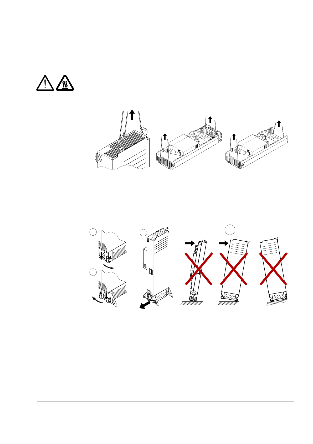
WARNING! Ignoring the following instructions can cause physical injury or death,
or damage to the equipment:
- Lift the drive module using the lifting lugs attached to the top and base of the
•
unit.
- Handle the drive module carefully. Make sure that the module does not fall
down when moving it on the floor and during installation and maintenance
work: Open the support legs by pressing each leg a little down (1, 2) and
turning it aside. When ever possible secure the module also with chains.
- Do not tilt the drive module (A). It is heavy (over 160 kg [350 lb]) and its
center of gravity is high. The module will overturn from a sideways tilt of 5
degrees. Do not leave the module unattended on a sloping floor.
17
Safety instructions
18
3AUA0000086323
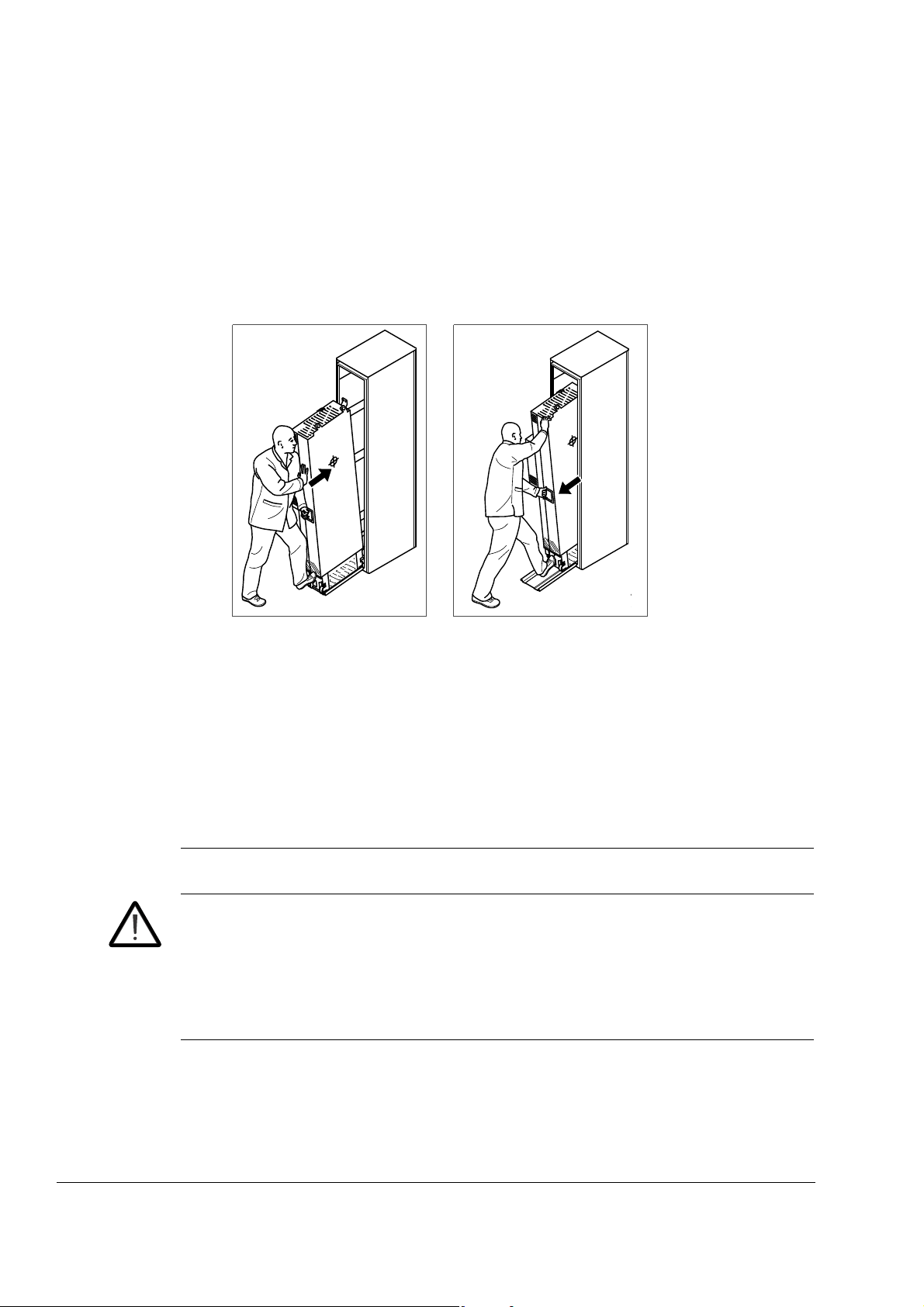
- Push the drive module into the cabinet and pull it from the cabinet carefully
preferably with help from another person as shown below. Keep a constant
pressure with one foot on the base of the module to prevent the module from
falling on its back. Use safety shoes with metal toe cap to avoid foot injury.
Do not use the ramp with plinth heights which exceed the maximum height
marked on the ramp next to the fastening screw. (The maximum plinth height
is 50 mm when the telescopic ramp is shortest and 150 mm when the ramp is
longest.) Tighten the two fastening bolts of the ramp carefully.
Beware of hot surfaces. Some parts, such as heatsinks of power
•
semiconductors, remain hot for a while after disconnection of the electrical
supply.
Make sure that dust from borings and grindings does not enter the drive when
•
installing. Electrically conductive dust inside the unit may cause damage or
malfunctioning.
Ensure sufficient cooling.
•
Do not fasten the drive by riveting or welding.
•
Fiber optic cables
WARNING! Ignoring the following instructions can cause equipment malfunction
and damage to the fiber optic cables:
Handle the fiber optic cables with care. When unplugging optic cables, always
•
grab the connector, not the cable itself. Do not touch the ends of the fibers with
bare hands as the fiber is extremely sensitive to dirt. The minimum allowed
bend radius is 35 mm (1.4 in.).
Safety instructions
Printed circuit boards
WARNING! Ignoring the following instructions can cause damage to the printed
circuit boards:
Wear a grounding wrist band when handling the boards. Do not touch the
•
boards unnecessarily. The printed circuit boards contain components sensitive
to electrostatic discharge.
Safe start-up and operation
General safety
These warnings are intended for all who plan the operation of the drive or operate
the drive.
WARNING! Ignoring the following instructions can cause physical injury or death,
or damage to the equipment:
Before adjusting the drive and putting it into service, make sure that the motor
•
and all driven equipment are suitable for operation throughout the speed range
provided by the drive. The drive can be adjusted to operate the motor at
speeds above and below the speed provided by connecting the motor directly
to the power line.
19
Do not activate any automatic fault reset functions of the drive control program
•
if dangerous situations can occur. When activated, these functions will reset
the drive and resume operation after a fault.
Do not control the motor with an AC contactor or disconnecting device;
•
instead, use the control panel keys and , or commands via the I/O
board of the drive. The maximum allowed number of charging cycles of the DC
capacitors, ie, power-ups by applying power, is five in ten minutes.
Note:
If an external source for start command is selected and it is ON, the drive will
•
start immediately after an input voltage break or fault reset unless the drive is
configured for 3-wire (a pulse) start/stop.
When the control location is not set to local, the stop key on the control panel
•
will not stop the drive.
Permanent magnet motor drives
WARNING! Do not run the motor over the rated speed. Motor overspeed leads to
overvoltage which may damage or explode the capacitors in the intermediate circuit
of the drive.
Safety instructions

20
Safety instructions

Introduction to the manual
What this chapter contains
This chapter describes the intended audience and contents of the manual. It
contains a flowchart of steps in checking the delivery, installing and commissioning
the drive. The flowchart refers to chapters/sections in this manual and other
manuals.
Target audience
This manual is intended for persons who
• plan the cabinet assembly of the drive module and install the module into a userdefined cabinet
• plan the electrical installation of the drive cabinet
• make instructions for the end user of the drive concerning the mechanical
installation of the drive cabinet, connection of power and control cables to the
cabinet-installed drive and maintenance of the drive.
21
Read the manual before working on the drive. You are expected to know the
fundamentals of electricity, wiring, electrical components and electrical schematic
symbols.
The manual is written for readers worldwide. Both SI and imperial units are shown.
Contents of the manual
This manual contains the instructions and information for the basic drive module
configuration. The chapters of the manual are briefly described below.
Safety instructions give safety instructions for the installation, commissioning,
operation and maintenance of the drive module.
Introduction to the manual introduces the manual.
Operation principle and hardware description describes the drive module.
Planning the cabinet installation guides in planning drive cabinets and installing the
drive module into a user-defined cabinet. The chapter gives cabinet layout examples
and free space requirements around the module for cooling.
Planning the electrical installation instructs in the motor and cable selection,
protections and cable routing.
Installation describes how to install the drive module into a cabinet and connect the
cables to the drive.
Installation checklist contains lists for checking the mechanical and electrical
installation of the drive.
Introduction to the manual
22
Start-up refers to the start-up instructions of the cabinet-installed drive.
Fault tracing describes the LED indications and refers to the fault tracing instructions
of the drive.
Maintenance contains preventive maintenance instructions.
Technical data contains the technical specifications of the drive module, eg, the
ratings, sizes and technical requirements, provisions for fulfilling the requirements for
CE and other markings.
Dimension drawings contains dimension drawings of the drive module installed into
a Rittal TS 8 cabinet.
Example circuit diagram shows an example circuit diagram for a cabinet-installed
drive module.
Resistor braking describes how to select, protect and wire brake resistors.
du/dt filters describes how to select du/dt filters for the drive.
Categorization by frame size and option code
The instructions, technical data and dimension drawings which concern only certain
drive frame sizes are marked with the symbol of the frame size (G1 or G2). The
frame size is marked on the type designation label.
The instructions and technical data which concern only certain optional selections
are marked with option codes, eg, +H381. The options included in the drive can be
identified from the option codes visible on the type designation label. The option
selections are listed in section Type designation key on page 35.
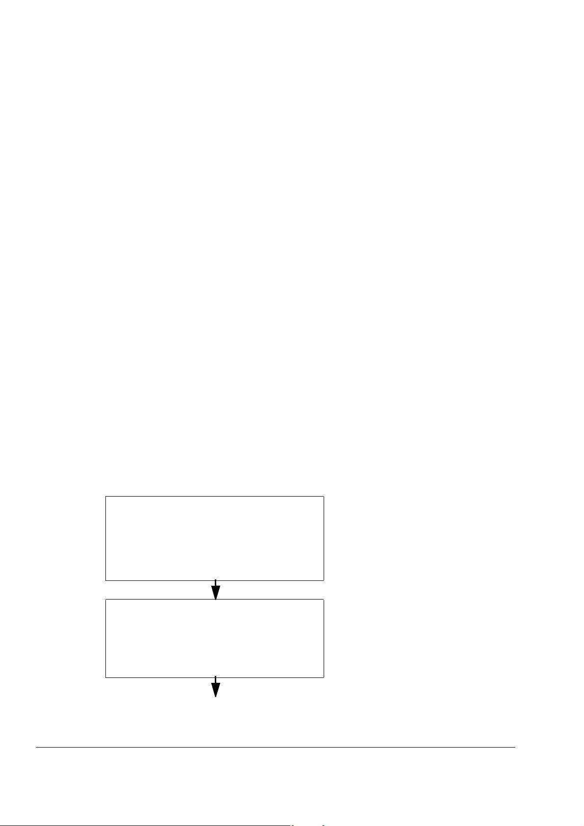
Quick installation, commissioning and operating flowchart
Task See
Plan the installation.
Check the ambient conditions, ratings, required
cooling air flow, input power connection, compatibility
of the motor, motor connection, and other technical
data.
Select the cables.
Unpack and check the units.
Check that all necessary optional modules and
equipment are present and correct.
Only intact units may be started up.
Planning the cabinet installation (page 37)
Planning the electrical installation (page 49)
Technical data (page 125)
Resistor braking (page 155)
Option manual (if optional equipment is
included)
Moving and unpacking the unit (page 74)
Checking the delivery (page 76)
If the drive module has been non-operational
for more than one year, the converter DC link
capacitors need to be reformed. (Reforming the
capacitors, page 124)
Introduction to the manual
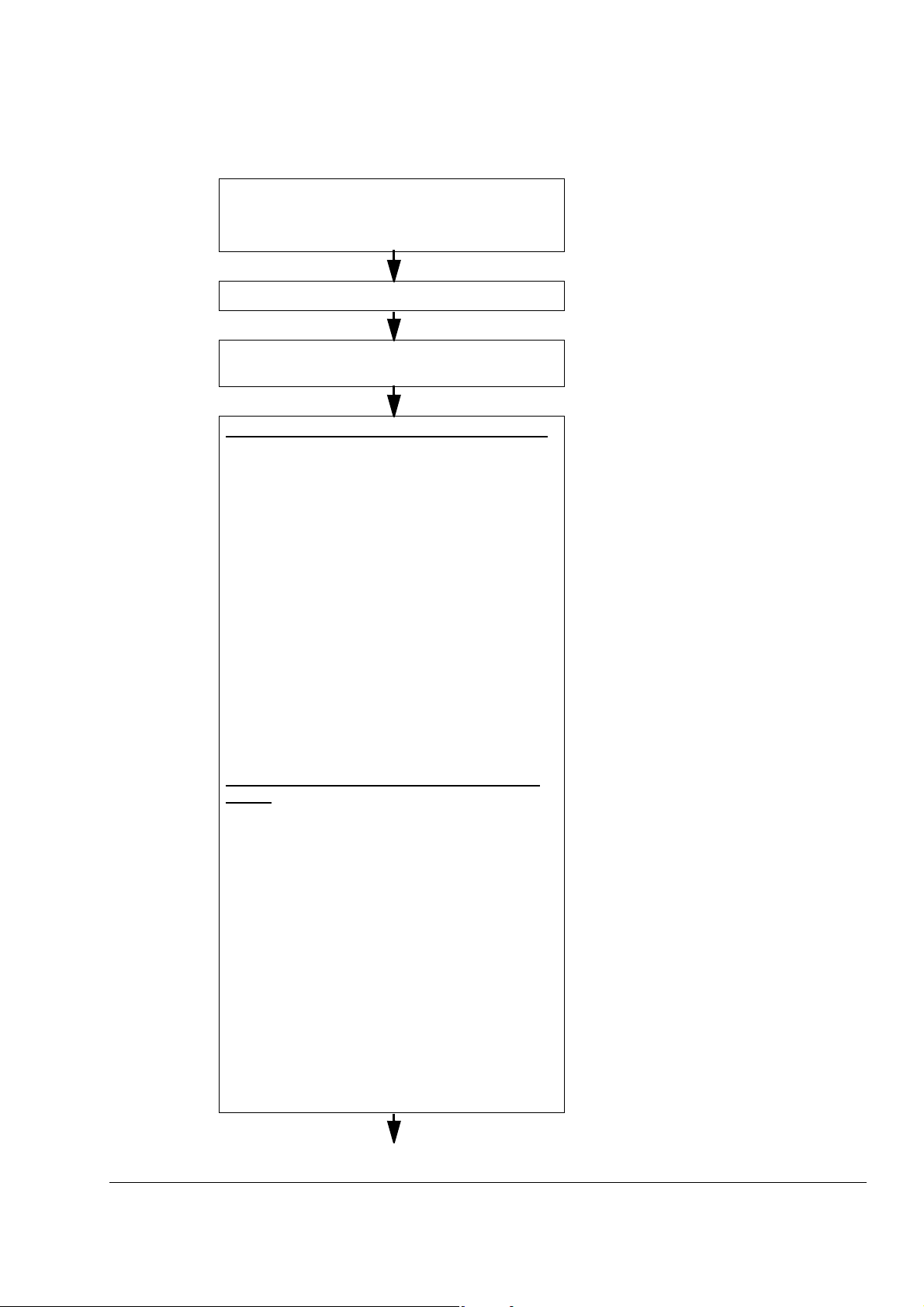
Task See
23
Check the installation site. Fasten the base of the
cabinet to floor.
Route the cables. Routing the cables (page 60)
Check the insulation of the supply cable, the motor
and the motor cable and the resistor cable (if present).
Units with optional cabling panels (+H
• Install the cabling panels into the cabinet.
• Install the additional components into the cabinet
(composition varies, for example: main disconnector,
main contactor, main AC fuses, etc.).
• If the main disconnector is installed into the cabinet,
connect the input power cabling to it.
• Connect the input power cables and motor cables to
the cabling panel terminals.
• Connect the brake resistor and DC connection
cables (if any) to the cabling panel terminals.
• Install the drive module into the cabinet.
• Fasten the cabling panel busbars to the drive module
busbars.
• If external drive control unit, connect the power
supply and fiber optic cables from the drive module to
the control unit and install the control unit into the
cabinet.
Units without optional cabling panels (no +H
+H383)
• Install the additional components into the cabinet
(composition varies, for example: main PE busbar,
main disconnector, main contactor, main AC fuses,
etc.).
• Install the drive module into the cabinet.
• Connect the power cabling between the drive module
and the rest of the main circuit components in the
cabinet (if any).
• Connect the input power cables and motor cables to
the drive cabinet.
• Connect the brake resistor and DC connection
cables to the drive cabinet.
• If external drive control unit, connect the power
supply and fiber optic cables from the drive module to
the control unit and install the control unit into the
cabinet.
381 or +H383)
381 or
Checking the installation site (page 73)
Ambient conditions (page 134)
Planning the cabinet installation (page 37)
Checking the insulation of the assembly (page
76)
Installing the mechanical accessories into the
cabinet (page 79)
Connecting the power cables (page 84)
Mounting the drive module into the cabinet
(page 89)
Connecting the external control unit to the drive
module (page 97)
Mounting the external control unit (page 99)
Manuals for any optional equipment
Introduction to the manual
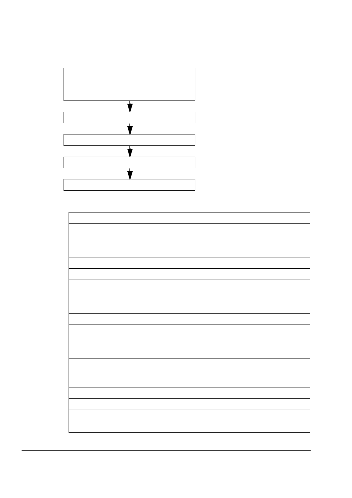
24
Task See
Connect the external control cables to the drive control
unit.
Check the installation. Installation checklist (page 109)
Commission the drive. Start-up (page 113)
Commission the brake chopper (if used). Resistor braking (page 155)
Operating of the drive: start, stop, speed control etc. Appropriate firmware manual
Terms and abbreviations
Term/Abbreviation Explanation
AIBP Input bridge protection board
APOW Power supply board
Connecting the control cables (page 95)
Control cable connection procedure of units
with internal control unit (option +P905), page
108
BFPS Power supply board
EMC Electromagnetic compatibility
EMI Electromagnetic interference
FCAN-01 Optional CANopen adapter module
FDNA-01 Optional DeviceNet™ adapter module
FECA-01 Optional EtherCAT
FEN-01 Optional TTL encoder interface module
FEN-11 Optional absolute encoder interface module
FEN-21 Optional resolver interface module
FEN-31 Optional HTL encoder interface
FENA-11 Optional Ethernet/IP™, Modbus/TCP and PROFINET IO fieldbus adapter
module
FIO-01 Optional digital I/O extension module
FIO-11 Optional analog I/O extension module
FIO-21 Optional analog and digital I/O extension module
FLON-01 Optional LonWorks
®
adapter module
®
adapter module
FPBA-01 Optional PROFIBUS DP adapter module
Introduction to the manual

Frame (size) Size of the drive module. The drive modules described in this manual are
of frame size G1 and G2.
FSCA-01 Optional Modbus adapter
HTL High-threshold logic
IGBT Insulated gate bipolar transistor; a voltage-controlled semiconductor type
widely used in converters due to their easy controllability and high
switching frequency.
I/O Input/Output
JCU The control unit of the drive module. The external I/O control signals are
connected to the JCU, or to optional I/O extension modules mounted on it.
JGDR Gate driver board
JINT Main circuit board
JMU-xx The memory unit attached to the control unit (JCU)
JRIB Adapter board connected to the control board in the control unit (JCU)
STO Safe torque off
25
SynRM Synchronous reluctance motor
RFI Radio-frequency interference
TTL
Transistor-transistor logic
Introduction to the manual

26
Introduction to the manual
Operation principle and hardware description
U1
V1
W1
U2
V2
W2
ACS850-04
R-
R+
421
5
3
UDC-
UDC+
PE
What this chapter contains
This chapter describes the operating principle and construction of the drive module
in short.
Product overview
The ACS850-04 is a drive module for controlling asynchronous AC induction motors,
permanent magnet motors and ABB synchronous reluctance motors (SynRM
motors).
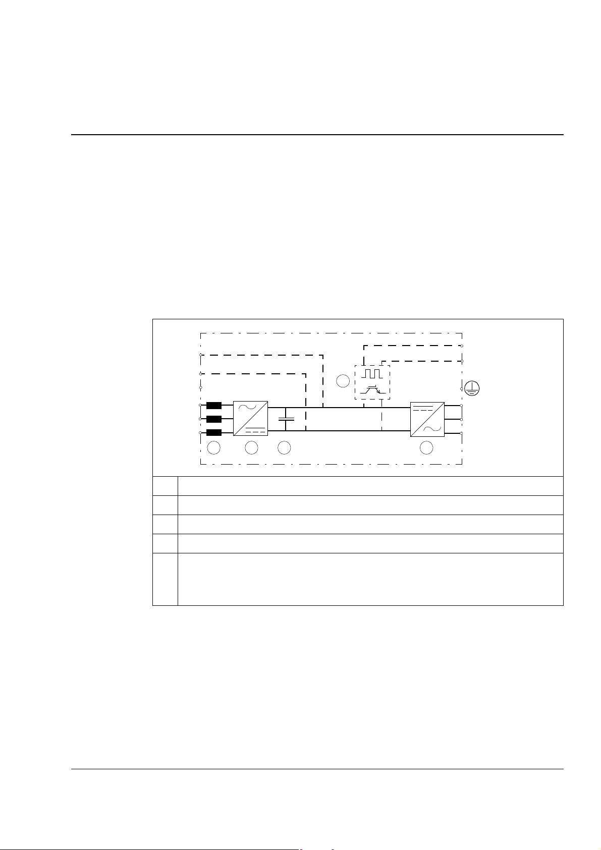
The main circuit of the drive module is shown below.
27
1 AC choke
2 Rectifier. Converts alternating current and voltage to direct current and voltage.
3 DC link. DC circuit between rectifier and inverter
4 Inverter. Converts direct current and voltage to alternating current and voltage.
5 Brake chopper (option +D150). Conducts the surplus energy from the intermediate circuit of
the drive to the brake resistor when necessary. The chopper operates when the DC link
voltage exceeds certain maximum limit. The voltage rise is typically caused by deceleration
(braking) of a high inertia motor.
Operation principle and hardware description
28
9
6
3
2
1
8
4
A
5
7
B
1
2
3
8
W1, V1, U1
W2, V2, U2
11
12
13
14 15
10
17
16
18
Layout
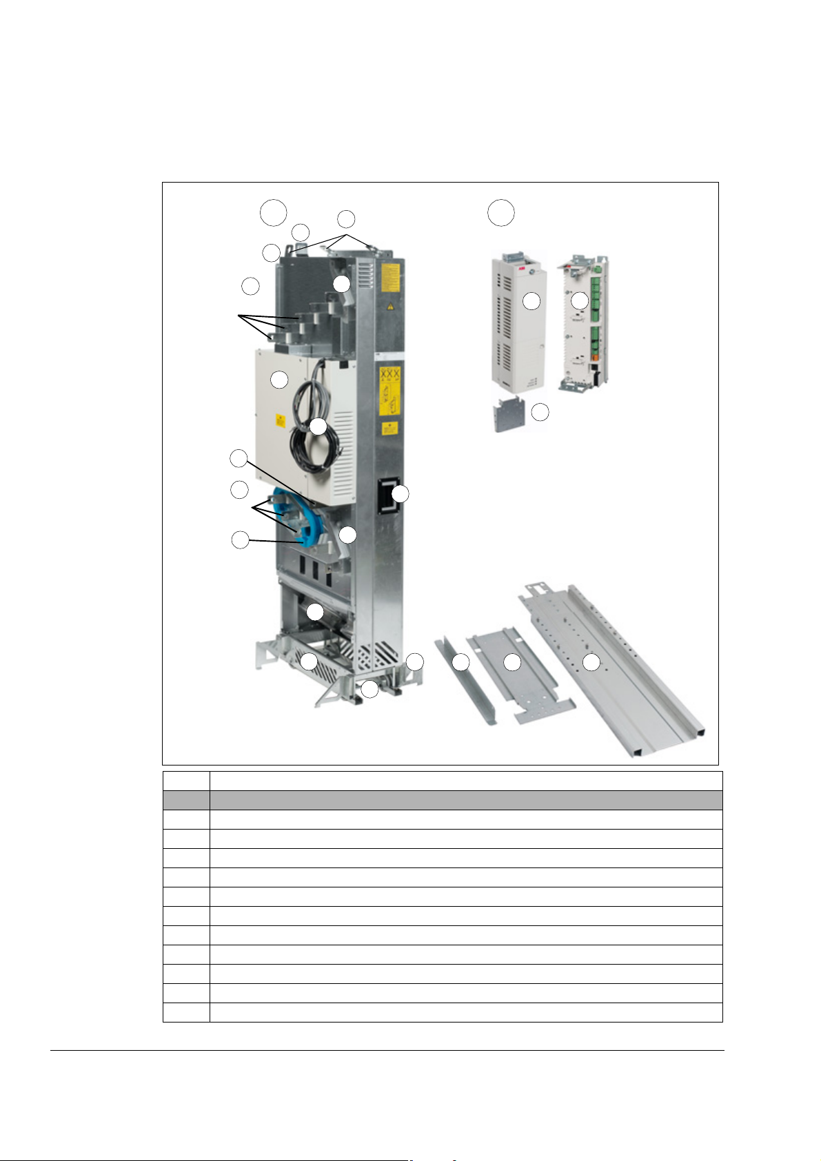
The components of the standard unit are shown below.
Item Description
A Drive module
1 Lifting lugs
2 Fastening bracket
3 Input cable connection busbars and optional DC+ and DC- busbars (+H356)
4 Circuit board compartment
5 Power supply and fiber optic cables to be connected to the external control unit
6 Output cable connection busbars and optional brake resistor connection busbars (+D150)
7 PE terminal
8 Control cable duct
9 Main cooling fans
10 Pedestal
11 Retractable support legs
Operation principle and hardware description

Item Description
12 Base fastening screws
13 Handle for pulling the drive module out of the cabinet
14 Pedestal guide plate
15 Telescopic extraction and insertion ramp
16 Top guide plate
17 Optional common mode filter (+E208)
18 Grounding busbar
B Control unit (JCU)
1 Control unit with front cover
2 Control unit with front cover removed
3 Control cable clamp plate
29
Operation principle and hardware description
30
3
1
2
3
a
A B
1
2
3
4
4
6
5
7
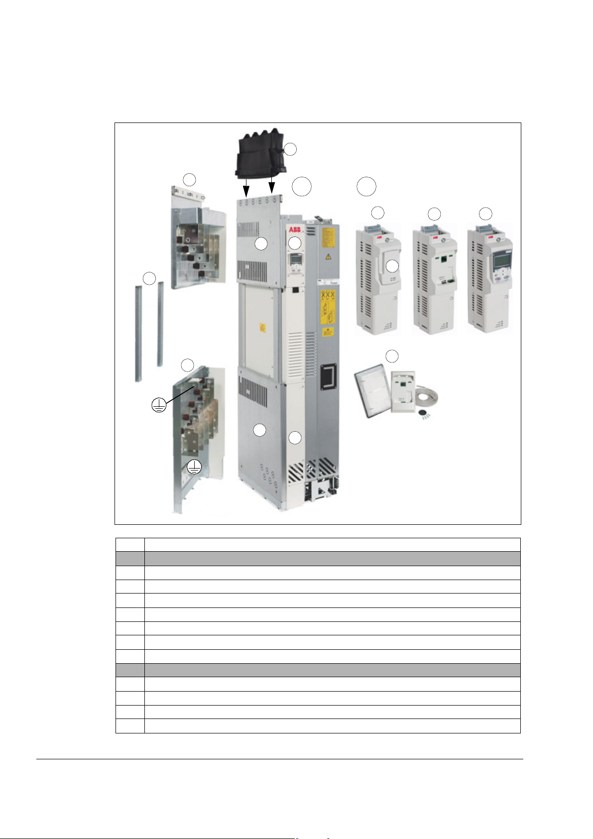
The drive module and optional selections are shown below: control unit and control
panel variations and cabling panels.
Item Description
A Drive module
1 Input power cabling panel to be fastened to the cabinet (+H381 or +H383)
2 Output power cabling panel to be fastened to the cabinet (+H381 or +H383)
3 Front cover. With option +P905, the control panel is placed on this cover.
4 Input power cabling panel (+H381 or +H383)
5 Side guides (+H381 or +H383)
6 Output power cabling panel (+H381 or +H383)
7 Rubber grommet (+H381)
B Control unit variants
1 Control unit with control panel holder (+J414)
2 Control unit with control panel holder (+J414) when cover (a) is removed
3 Control unit with control panel (+J400)
4 Control panel door mounting kit (+J410)
Operation principle and hardware description

31
Slots 1 and 2 for
optional I/O extension
and encoder/resolver
interface modules
Slot 3 for optional
fieldbus adapter
module
Relay outputs
+24VD
Digital inputs
Digital input/outputs
Analog inputs
Analog outputs
Drive-to-drive link
Control panel / PC connection
Memory unit (JMU) connection
External 24 V power input
Safe torque off connection
The control unit layout is shown below (cover assembly and protective coverings of
the slots removed).
Operation principle and hardware description

32
Slot 1
Slot 2
Slot 3
F
X
X
X
F
X
X
U2
V2
W2
UDC-
X7
M
3 ~
XPOW
XRO1…3
XD24
XDI
XDIO
XAI
XAO
XD2D
XSTO
2
4
U1
V1
W1
L1
L2
L3
PE
PE
UDC+
R-
R+
t°
3
1
F
X
X
Power connections and control interfaces
The diagram shows the power connections and control interfaces of the drive
module.
Slot 1 and
Slot 2
Operation principle and hardware description
Slot 3 Fieldbus adapter modules (FCAN-01, FDNA-01,
XPOW External power input
XRO1…3 * Relay outputs (3 pcs)
XD24 24 V DC output
XDI * Digital inputs (6 pcs)
XDIO * Digital input/outputs (2 pcs)
XAI * Analog inputs
XAO * Analog outputs
XD2D Drive-to-drive link
XSTO Safe torque off
I/O extension modules (FIO-01, FIO-11, FIO-21)
and/or encoder or resolver interface modules
(FEN-01, FEN-11, FEN-21, FEN-31)
FENA-11, FECA-01, FLON-01, FSCA-01,
FPBA-01)
1) For information on the default
connections, see page 104. For the
specifications, see page 131.
* programmable
2) Memory unit, see page 124.
3) Brake resistor (optional)
4) du/dt or sine filter (optional, see
page 161)

External control unit connection cables
3 m (9.8 ft)
JINT
APOW
3 m (9.8 ft)
2560 mm (8.4 ft)
Category 5e cable
JRIB
8
0
(
3
.
1
5
”
)
JCU
ACS850-04
JGDR
The cables for connecting the drive module and control panel to the control unit are
shown below. See sections Connecting the external control unit to the drive module
(page 97) and Connecting a PC (page 108) for the actual connections.
33
Operation principle and hardware description

34
No. Description
1 Type designation, see section Type designation key on page 35.
2Frame size
3Ratings
4 Valid markings
5 Serial number. The first digit of the serial number refers to the manufacturing plant. The next
four digits refer to the unit’s manufacturing year and week, respectively. The remaining
digits complete the serial number so that there are no two units with the same number.
1
2
3
4
5
Type designation label
The type designation label includes an IEC and NEMA rating, CE and cULus, and
CSA markings, a type designation and a serial number, which allow individual
recognition of each unit. The type designation label is located on the front cover. An
example label is shown below.
Operation principle and hardware description

Type designation key
The type designation contains information on the specifications and configuration of
the drive module. The first digits from left express the basic configuration. The
optional selections are given thereafter, separated by plus signs, eg, +E208. The
main selections are described below. Not all selections are available for all types.
For more information, refer to ACS850-04 Ordering Information
(3AXD00000579470), available on request.
Code Description
Basic code, eg, ACS850-04-710A-5
Product series
ACS850 ACS850 product series
Type
04 Air-cooled drive module. When no options are selected: IP00 (UL type open), top entry and
bottom exit for cables (terminals at the side of the module), external JCU control unit with a
front cover but no control panel, Standard Control Program, AC choke, coated boards, Safe
torque off function, pedestal guide plate, extraction and insertion ramp, module fastening
bracket and screws, hardware manual, multilingual quick start-up guide and CD containing
all manuals.
Size
xxxA Refer to the rating tables, page 125.
Voltage range
5 380…500 V AC
Option codes (plus codes)
Resistor braking
D150 Brake chopper and brake resistor connection busbars, and R+ and R- terminals in the power
cabling panel (+H381 or +H383) if the power cabling panels are ordered
Filters
E208 Common mode filter. Includes three extension busbars to the drive module output busbars
with units without option +H381 or +H383.
Cabling panels
H381 Power cabling panels (U1, V1, W1, U2, V2, W2 terminals) to be installed in the cabinet,
rubber grommet that gives the unit an IP20 protection class.
H383 Power cabling panels (U1, V1, W1, U2, V2, W2 terminals) to be installed in the cabinet,
degree of protection: IP00.
DC busbars
H356 DC output busbars, and DC+ and DC- terminals in the power cabling panel (+H381 or
+H383) if the power cabling panels are ordered
Pedestal
0H354 No pedestal
Control panel and control unit
J400 Control panel inserted onto the JCU control unit. Includes control panel mounting platform
and internal cable.
J410 Control panel with a door mounting kit. Includes control panel mounting platform, IP54 cover
and a 3-meter panel connection cable.
J414 Control panel holder with cover and internal cable but no control panel. Not to be used with
+J400.
0C168 Without front cover for the JCU control unit
P905 JCU control unit inside the circuit board compartment of drive module.
35
Operation principle and hardware description

36
Code Description
Fieldbus adapter modules
K451 FDNA-01 DeviceNet™ fieldbus adapter module
®
K452 FLON-01 LonWorks
fieldbus adapter module
K454 FPBA-01 PROFIBUS DP fieldbus adapter module
K457 FCAN-01 CANopen fieldbus adapter module
K458 FSCA-01 Modbus fieldbus adapter module
®
K469 FECA-01 EtherCAT
fieldbus adapter module
K473 FENA-11 Ethernet/IP™, Modbus/TCP and PROFINET IO fieldbus adapter module
I/O extension and feedback interface modules
L500 FIO-11 analog I/O extension module
L501 FIO-01 digital I/O extension module
L502 FEN-31 HTL incremental encoder interface module
L516 FEN-21 resolver interface module
L517 FEN-01 TTL incremental encoder interface module
L518 FEN-11 TTL absolute encoder interface module
L519 FIO-21 analog and digital I/O extension module
Control programs
N2007 Standard control program version UIFI2110 (frame G2 only)
N2008 Standard control program version UIFI2200 (frame G2 only)
N2009 Standard control program version UIFI2210 (frame G2 only)
N2010 Standard control program version UIFI2300 (frame G2 only)
N3050 Crane technology library
N5050 Crane control program. Requires option +N3050.
N7502 SynRM control program
Warranty
P904 Extended warranty
ATEX-certified function
Q971 ATEX-certified Safe motor disconnection function using the drive Safe torque off function
Paper manuals. Note: The delivered manual set may include manuals in English if the translation is
not available.
R700 English
R701 German
R702 Italian
R703 Dutch
R704 Danish
R705 Swedish
R706 Finnish
R707 French
R708 Spanish
R709 Portuguese
R710 Portuguese spoken in Brazil
R711 Russian
R714 Turkish
Operation principle and hardware description

Planning the cabinet installation
What this chapter contains
This chapter guides in planning drive cabinets and installing the drive module into a
user-defined cabinet so that the front of the module faces the cabinet door. The
chapter gives cabinet layout examples and free space requirements around the
module for cooling. The issues discussed are essential for the safe and trouble-free
use of the drive system.
Limitation of liability
The installation must always be designed and made according to applicable local
laws and regulations. ABB does not assume any liability whatsoever for any
installation which breaches the local laws and/or other regulations.
Basic requirements for the cabinet
37
Use a cabinet which:
• has a frame sturdy enough to carry the weight of the drive components, control
circuitry and other equipment installed in it
• protects the user and drive module against contact and meets the requirements
for dust and humidity
• has sufficient air inlet and outlet gratings that allow free flow of cooling air through
the cabinet. This is critical for proper cooling of the drive module.
Planning the layout of the cabinet
Design a spacious layout to ensure easy installation and maintenance. Sufficient
cooling air flow, obligatory clearances, cables and cable support structures all
require space.
Place the control board(s) away from:
• main circuit components such as contactor, switches and power cables
• hot parts (heat sink, air outlet of the drive module).
Planning the cabinet installation

38
1a
4
3
2a2b
5
6
1a*)Air inlet for the drive module
1b Air inlet for the other equipment. An extra fan is not necessary if an
extra air baffle is used on the cabinet roof (see next page).
1c*
)
Air inlet for circuit boards and DC and output busbars
2a*
)
Air outlet with an extra exhaust fan for the drive module
2b*
)
Air outlet for the other equipment
2c*
)
Air outlet for the drive module and other equipment on the cabinet
roof. An exhaust fan if needed. We recommend this alternative
instead of 2a.
3 Drive control panel with DPMP-01 mounting platform (option
+J410). The control panel is connected to the JCU control unit
inside the cabinet.
4 Contactor control switch and emergency stop switch (connected to
the contactor control circuit inside the cabinet)
5 Operating handle of the disconnector
6 Rubber grommets for degree of protection
7 Roof air flow viewed from top
*
)
Note: The sizes of the air inlet and outlet gratings are critical for
proper cooling of the drive module. For losses and cooling data
requirements, see page 129.
7
1c
1b
2c
Layout examples, door closed
This diagram shows a cabinet layout example with the input power cable leadthrough from top and the motor cable lead-through from bottom.
Layout example, door open
Planning the cabinet installation
This diagram shows a layout example when optional cabling panels are not used.

39
1 Supporting frame of the cabinet 9 JCU control unit.
2 Vertical (2a, 2b) and horizontal (2c, 2d) air
baffles that separate the cool and hot
areas (leak-proof lead-throughs). See also
page 46.
Note: With an internal control unit (option +P905), the
air inlet 17 is critical for proper cooling of the control
board.
2e Optional air baffle that is needed when 10 External control cables
there is no fan on the lower part of the 11 Grounding screws
cabinet door (see 1b on page 38). 12 Alternative to grounding screws (11)
3 Cabinet grounding busbar (PE) 13 Air flow to the roof
4 Input power cable including the protective 14 Air flow through the drive module (side view)
ground conductor (PE) of the drive 15 Air inlet gratings in the cabinet door
5 Disconnector and fuses 16 Air inlet for the brake option
6 Contactor 17 Air inlet for circuit boards and DC and output busbars
7 Drive module
8 Motor cable including the protective
ground conductor of the drive
PE
U1
V1
W1
W2
V2
U2
1
4
5
6
7
8
3
2a
11
2a
12
13
14
9
10
2b
3
2c
2d
15
2e
2e
16
17
Planning the cabinet installation

40
Note 1: The power cable shields can also be grounded to the drive module
grounding terminals.
Note 2: See also section Required free space, page 47.
Arranging the grounding inside the cabinet
Arrange the grounding of the drive module by leaving the contact surfaces of the
fastening points unpainted (bare metal-to-metal contact). The module frame will be
grounded to the PE busbar of the cabinet via the fastening surfaces, screws and the
cabinet frame. Alternatively, use a separate grounding conductor between the PE
terminal of the drive module and the PE busbar of the cabinet.
Ground also the other components in the cabinet according to the principle above.
Selecting the busbar material and preparation of the joints
If planning the use of busbars, note the following:
• Tin-plated copper is recommended but aluminium can also be used.
• The oxide layer from aluminium busbar joints must be removed and suitable antioxidant joint compound applied.
Tightening torques
Apply the following torques to grade 8.8 screws (with or without joint compound) that
tighten electric contacts.
Screw size Torque
M5 3.5 N·m (2.6 lbf·ft)
M6 9 N·m (6.6 lbf·ft)
M8 20 N·m (14.8 lbf·ft)
M10 40 N·m (29.5 lbf·ft)
M12 70 N·m (52 lbf·ft)
M16 180 N·m (133 lbf·ft)
Planning the fastening of the cabinet
Note the following when planning the fastening of the cabinet:
• Fasten the cabinet to the floor from the front and to the floor or wall from the back.
• Always fasten the drive module from its fastening points to the cabinet. For
details, see the module installation instructions.
WARNING! Do not fasten the cabinet by electric welding. ABB does not assume any
liability for damages caused by electric welding as the welding circuit may damage
electronic circuits in the cabinet.
Planning the cabinet installation

Planning the cabinet placement on a cable channel
The carrying structure on a cable channel Cabinet side view with a bottom plate
Note the following when planning to place the cabinet on a cable channel:
• The cabinet structure must be sturdy enough. If the whole cabinet base will not be
supported from below, the cabinet weight will lie on the sections that the floor
carries.
• Equip the cabinet with a sealed bottom plate and cable lead-throughs to ensure
the degree of protection and to prevent the cooling air flow from the cable channel
into the cabinet.
41
Planning the electromagnetic compatibility (EMC) of the cabinet
Note following when planning the electromagnetic compatibility of the cabinet:
• Generally, the fewer and smaller the holes in the cabinet, the better the
interference attenuation. The maximum recommended diameter of a hole in
galvanic metal contact in the covering cabinet structure is 100 mm. Pay special
attention to the cooling air inlet and outlet gratings.
• The best galvanic connection between the steel panels is achieved by welding
them together as no holes are necessary. If welding is not possible, the seams
between the panels are recommended to be left unpainted and equipped with
special conductive EMC strips to provide adequate galvanic connection. Usually,
reliable strips are made of flexible silicon mass covered with a metal mesh. The
non-tightened touch-contact of the metal surfaces is not sufficient, so a
conductive gasket between the surfaces is required. The maximum
recommended distance between assembly screws is 100 mm.
• Construct sufficient high-frequency grounding network in the cabinet to avoid
voltage differences and forming of high-impedance radiator structures. A good
high-frequency grounding is made with short flat copper braids for low
inductance. One-point high-frequency grounding cannot be used due to the long
distances inside the cabinet.
Planning the cabinet installation

42
Cable ties
Knitted wire mesh
Bare cable shield
Cabinet bottom plate
Lead-through plate
Cable
Shielding cushion
(conductive)
Cable
Cable grommet
Bare cable shield
Cabinet bottom plate
• 360° high frequency grounding of the cable shields at the cable lead-throughs
improves the EMC shielding of the cabinet.
• 360° high frequency grounding of the motor cable shields at their entries is
recommended. The grounding can be implemented by a knitted wire mesh
screening as shown below.
• 360° high frequency grounding of the control cable shields is recommended at
their entries. The shields can be grounded by means of conductive shielding
cushions pressed against the cable shield from both directions:
Planning the cabinet installation

Planning the grounding of the cable shields at the cabinet lead-through
Example cable lead-through
1 To power cable terminals
2 Cable shield
3 PE (ground) terminal of the cabinet, cabling panel or
drive module
4 Stripped part of the cable
5 EMC sleeve
6 Lead-through plate
7 Base plate
8 Strain relief
9 Conductive shielding cushions for control cables
1
2
3
4
5
6
7
8
9
Follow the principle shown below when planning the grounding of the cable shields
at the cabinet lead-through.
43
Planning the cooling
Note following guidelines when planning the cooling of the cabinet:
• Ventilate the installation site sufficiently so that the cooling air flow and ambient
temperature requirements of the drive module are met, see pages 129 and 134.
The internal cooling fan of the drive module rotates at a constant speed thus
blowing constant air flow through the module. Whether the same amount of air
must be replaced all the time in the facility depends on how much heat must be
removed.
Planning the cabinet installation
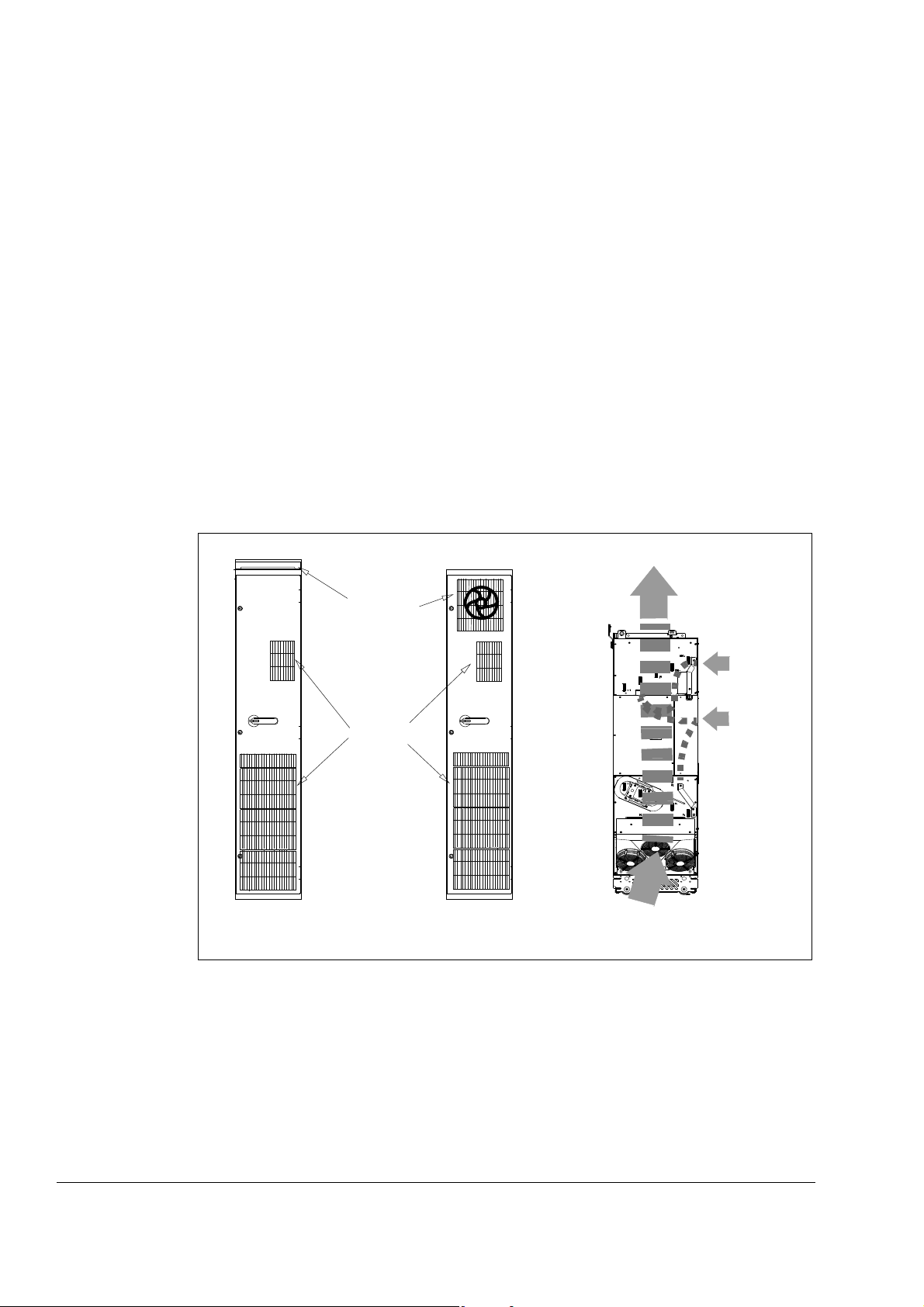
44
Air inlet
Air outlet
Air flow inside the drive module
Air inlets and outlets on the cabinet door
• Leave enough free space around the components to ensure sufficient cooling.
Observe the minimum clearances given for each component. For the required
free space around the drive module, see page 47.
• Also ventilate the heat dissipated by cables and other additional equipment.
• Make sure that the air inlets and outlets are large enough to allow sufficient
air flow in and out of the cabinet. This is critical for proper cooling of the drive
module.
• Equip the air inlets and outlets with gratings that:
- guide the air flow
- protect against contact
- prevent water splashes from entering the cabinet.
• The drawing below shows two typical cabinet cooling solutions. The air inlet is at
the bottom of the cabinet, while the outlet is at the top, either on the upper part of
the door or on the roof. We recommend that the air outlet is on the cabinet roof.
Use an extra exhaust fan if the air outlet is on the cabinet door.
• The internal cooling fans of the drive modules and reactors/chokes are usually
sufficient to keep the component temperatures low enough in IP22 cabinets.
• In IP54 cabinets, thick filter mats are used to prevent water splashes from
entering the cabinet. This entails the installation of additional cooling equipment,
such as a hot air exhaust fan.
Planning the cabinet installation

Preventing the recirculation of hot air
Prevent hot air circulation outside the cabinet by leading the outcoming hot air away
from the area where the inlet air to the cabinet is taken. Possible solutions are listed
below:
• gratings that guide air flow at the air inlet and outlet
• air inlet and outlet at different sides of the cabinet
• cool air inlet in the lower part of the front door, and an extra exhaust fan on the
roof of the cabinet.
Prevent hot air circulation inside the cabinet with, for example, leak-proof air baffles
at the positions shown in the diagram below. No gaskets are usually required.
1a Air flow to the drive module, max. 40 °C (104 °F) 3 Drive module
1b Air inlet to the drive circuit boards and DC and output busbars 4 Disconnector and fuses
2a Vertical air baffle that separates the cool and hot areas in the cabinet 5 Contactor
2b Vertical air baffle 6 JCU control unit
2c Upper horizontal air baffle 7 Air flow out
2d Lower horizontal air baffle
2e Optional air baffle that is needed when there is no fan on the lower
part of the cabinet door (see 1b on page 38).
45
Planning the cabinet installation

46
1a
7
PE
U1
V1
W1
W2
V2
U2
3
2a
2c
2b
3
C
C
C – C
B
B
A
A
2a
2c
B - B
A - A
2c
3
2a
2a
2b
2c
3
2d
2a
2d
4
5
6
X
Y
X
Y
2e
2e
1b
2d
2e
2d
3
2b
2b
Planning the cabinet installation
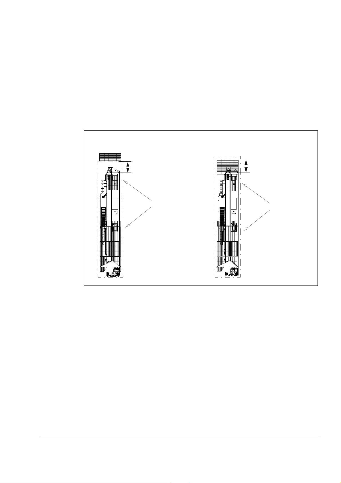
Required free space
270 mm (10.63 in.)
Air outlet in the cabinet door
290 mm (11.42 in.)
Air outlet on the cabinet roof
Air inlet
Air inlet
Free space around the drive module is needed for ensuring that sufficient cooling air
flows through the module and the module cools properly.
Free space at the top of the drive module
The required free space at the top of the module is shown below when a) the air
outlet is on the cabinet roof or b) on the upper part of the cabinet door. The air inlets
on the cabinet door are also shown.
47
Free space around the drive module
20 mm (0.79 in.) free space around the drive module is required from the cabinet
back panel and front door. No free space for cooling is required on the left- and righthand sides of the module.
The module is designed to be installed in a cabinet with the following measurements:
width 400 mm (15.75 in.), depth 600 mm (23.62 in.) and height 2000 mm (78.74 in.).
Other installation positions
Contact your local ABB representative.
Planning the cabinet installation

48
Planning the placement of the control panel
Note the following alternatives when planning the placement of the control panel:
• The control panel can be snapped on the control unit of the drive. See page 30.
• The control panel can be mounted onto the cabinet door using the control panel
mounting kit (+J410). For the installation instructions, refer to ACS-CP-U Control
Panel IP54 Mounting Platform Kit (+J410) Installation Guide (3AUA0000049072
[English]).
Planning the use of the cubicle heaters
Use a cubicle heater if there is a risk of condensation in the cabinet. Although the
primary function of the heater is to keep the air dry, it may also be required for
heating at low temperatures.
Planning the cabinet installation

Planning the electrical installation
What this chapter contains
This chapter contains the instructions that you must follow when selecting the motor,
cables, protections, cable routing and way of operation for the drive system.
Note: The installation must always be designed and made according to applicable
local laws and regulations. ABB does not assume any liability whatsoever for any
installation which breaches the local laws and/or other regulations. Furthermore, if
the recommendations given by ABB are not followed, the drive may experience
problems that the warranty does not cover.
Selecting the supply disconnecting device
Install a hand-operated input disconnecting device between the AC power source
and the drive. The disconnecting device must be of a type that can be locked to the
open position for installation and maintenance work.
49
European Union
To meet the European Union Directives, according to standard EN 60204-1, Safety
of Machinery, the disconnecting device must be one of the following types:
• switch-disconnector of utilization category AC-23B (EN 60947-3)
• disconnector that has an auxiliary contact that in all cases causes switching
devices to break the load circuit before the opening of the main contacts of the
disconnector (EN 60947-3)
• circuit breaker suitable for isolation in accordance with EN 60947-2.
Other regions
The disconnecting device must conform to the applicable safety regulations.
Selecting and dimensioning the main contactor
If a main contactor is used, its utilization category (number of operations under load)
must be AC-1 according to IEC 60947-4, Low-voltage switchgear and controlgear.
Dimension the main contactor according to the nominal voltage and current of the
drive.
Planning the electrical installation

50
Protecting the motor insulation and bearings
The drive employs modern IGBT inverter technology. Regardless of frequency, the
drive output comprises pulses of approximately the drive DC bus voltage with a very
short rise time. The pulse voltage can almost double at the motor terminals,
depending on the attenuation and reflection properties of the motor cable and the
terminals. This can cause additional stress on the motor and motor cable insulation.
Modern variable speed drives with their fast rising voltage pulses and high switching
frequencies can generate current pulses that flow through the motor bearings, which
can gradually erode the bearing races and rolling elements.
Optional du/dt filters protect motor insulation system and reduce bearing currents.
Common mode filters mainly reduce bearing currents. Insulated N-end (non-drive)
bearings protect the motor bearings. See section Checking the compatibility of the
motor and drive below for the required filters and N-end bearings to be used with the
drive. Select and install the cables according to the instructions given in the
hardware manual.
Checking the compatibility of the motor and drive
Use an asynchronous AC induction motor, a permanent magnet motor or an ABB
synchronous reluctance motor (SynRM) with the drive. Several induction motors can
be connected at a time but only one permanent magnet motor.
Select the motor and drive according to the rating tables in chapter Technical data.
Use the DriveSize PC tool if the default load cycles are not applicable.
1. Check that the motor ratings lie within the allowed ranges of the drive control
program:
• motor nominal voltage is in the range of 1/2...2 · U
N
• motor nominal current is 1/6 ... 2 · IHd of the drive in DTC control and
0 ... 2 · I
in scalar control. The control mode is selected by a control program
Hd
parameter.
2. Check that the motor voltage rating meets the application requirements:
When … the motor voltage rating should be …
No resistor braking is in use U
Frequent or long term brake cycles will
be used
U
Input voltage of the drive
N
N
1.21
· U
N
See section Additional requirements for the braking applications on page 53.
3. Consult the motor manufacturer before using a motor in a drive system where the
motor nominal voltage differs from the AC power source voltage.
4. Ensure that the motor insulation system withstands the maximum peak voltage in
the motor terminals. See the Requirements table below for the required motor
insulation system and drive filtering.
Planning the electrical installation

Example 1: When the supply voltage is 440 V and the drive is operating in the motor
mode only, the maximum peak voltage in the motor terminals can be approximated
as follows: 440 V · 1.35 · 2 = 1190 V. Check that the motor insulation system
withstands this voltage.
Requirements table
The following table shows how to select the motor insulation system and when
optional ABB du/dt filters, insulated N-end (non-drive end) motor bearings and ABB
common mode filters are required. Failure of the motor to fulfil the following
requirements or improper installation may shorten motor life or damage the motor
bearings and voids the warranty.
51
Motor type Nominal mains
Manufacturer
A
Randomwound M2_,
B
M3_ and
B
M4_
Form-wound
HX_ and
AM_
Old* formwound HX_
and modular
Randomwound HX_
and AM_ **
HDP Consult the motor manufacturer.
voltage (AC line
voltage)
< 500 V Standard - + N + N + CMF
U
N
500 V < U
600 V < U
(cable length <
150 m)
600 V < U
(cable length >
150 m)
380 V < U
380 V < U
0 V < U
500 V < U
< 600 V Standard + du/dt + du/dt + N + du/dt + N + CMF
N
< 690 V
N
< 690 V
N
< 690 V Standard n.a. + N + CMF PN < 500 kW: + N +
N
< 690 V Check with the motor
N
< 500 V Enamelled wire with
N
< 690 V + du/dt + N + CMF
N
Requirement for
Motor insulation
system
or
Reinforced - + N + N + CMF
Reinforced + du/dt + du/dt + N + du/dt + N + CMF
Reinforced - + N + N + CMF
manufacturer.
fibre glass taping
ABB du/dt filter, insulated N-end bearing and ABB common mode
filter
P
< 100 kW
N
and
frame size < IEC 315
< 134 hp
P
N
and
frame size <
NEMA 500
+ du/dt with voltages over 500 V + N + CMF
+ N + CMF
100 kW <
frame size >
134 hp < PN < 469 hp
PN < 350 kW
or
IEC 315
or
frame size >
NEMA 500
P
> 350 kW
N
or
frame size >
P
> 469 hp
N
or
frame size >
NEMA 580
CMF
P
> 500 kW: + N +
N
CMF + du/dt
IEC 400
Planning the electrical installation

52
Motor type Nominal mains
voltage (AC line
Manufacturer
N
Randomwound and
O
form-wound
N
-
A
B
B
< 420 V Standard: ÛLL=
U
N
420 V < U
500 V < U
600 V < U
* manufactured before 1.1.1998
** For motors manufactured before 1.1.1998, check for additional instructions with the motor
*** If the intermediate DC circuit voltage of the drive is increased from the nominal level by resistor
The abbreviations are defined below.
Requirement for
voltage)
< 500 V Standard: ÛLL= 1300 V+ du/dt + du/dt + N + du/dt + N + CMF
N
< 600 V Reinforced: ÛLL =
N
< 690 V Reinforced: ÛLL=
N
Motor insulation
system
1300 V
or
Reinforced: Û
1600 V, 0.2
micros econd rise tim e
1600 V
or
Reinforced: Û
1800 V
1800 V
Reinforced: Û
2000 V, 0.3
micros econd rise tim e
***
LL
LL
LL
ABB du/dt filter, insulated N-end bearing and ABB common mode
< 100 kW
P
N
and
frame size < IEC 315
< 134 hp
P
N
and
frame size <
NEMA 500
- + N or CMF + N + CMF
=
- + N or CMF + N + CMF
+ du/dt + du/dt t + N + du/dt+ N + CMF
=
- + N or CMF + N + CMF
+ du/dt + du/dt + N + du/dt + N + CMF
- N + CMF N + CMF
=
100 kW <
frame size >
134 hp < PN < 469 hp
or
+ du/dt + CMF
or
+ du/dt + CMF
filter
PN < 350 kW
or
IEC 315
or
frame size >
NEMA 500
P
frame size >
P
frame size >
NEMA 580
> 350 kW
N
or
IEC 400
> 469 hp
N
or
manufacturer.
braking, check with the motor manufacturer if additional output filters are needed in the applied drive
operation range.
Abbreviation Definition
U
N
Û
LL
P
N
du/dt du/dt filter at the output of the drive
CMF Common mode filter +E208
N N-end bearing: insulated motor non-drive end bearing
n.a. Motors of this power range are not available as standard units. Consult the motor
Planning the electrical installation
Nominal voltage of the supply network
Peak line-to-line voltage at motor terminals which the motor insulation must
withstand
Motor nominal power
manufacturer.

Additional requirements for explosion-safe (EX) motors
If you will use an explosion-safe (EX) motor, follow the rules in the requirements
table above. In addition, consult the motor manufacturer for any further
requirements.
Additional requirements for HXR and AMA motors
All AMA machines (manufactured in Helsinki) for drive systems have form-wound
windings. All HXR machines manufactured in Helsinki starting 1.1.1998 have formwound windings.
Additional requirements for ABB motors of types other than M2_, M3_, M4_, HX_ and AM_
Use the selection criteria given for non-ABB motors.
Additional requirements for the braking applications
When the motor brakes the machinery, the intermediate circuit DC voltage of the
drive increases, the effect being similar to increasing the motor supply voltage by up
to 20 percent. Consider this voltage increase when specifying the motor insulation
requirements if the motor will be braking a large part of its operation time.
53
Example
: Motor insulation requirement for a 400 V drive must be selected as if the
motor were supplied with 480 V.
Additional requirements for ABB high-output motors and IP23 motors
The rated output power of high output motors is higher than what is stated for the
particular frame size in EN 50347:2001. This table shows the requirements for ABB
random-wound motor series (for example, M3AA, M3AP and M3BP).
Nominal AC supply
voltage
< 500 V Standard - + N + N + CMF
U
N
500 V < U
600 V < U
< 600 V Standard + du/dt + N + du/dt + N + du/dt + CMF
N
< 690 V Reinforced + du/dt + N + du/dt + N + du/dt + CMF
N
Motor insulation
system
or
Reinforced - + N + N + CMF
ABB du/dt and common mode filters, insulated N-end motor
< 100 kW 100 kW < PN < 200 kW PN > 200 kW
P
N
P
N
Requirement for
bearings
< 140 hp 140 hp < PN < 268 hp PN > 268 hp
Planning the electrical installation

54
Additional requirements for non-ABB high-output and IP23 motors
The rated output power of high output motors is higher than what is stated for the
particular frame size in EN 50347:2001. The table below shows the requirements for
random-wound and form-wound non-ABB motors with nominal power smaller than
350 kW. For bigger motors, consult the motor manufacturer.
Nominal AC
supply voltage
Motor insulation
system
< 420 V Standard: ÛLL=
U
N
ABB du/dt filter, insulated N-end bearing and ABB common
P
< 100 kW or frame
N
size < IEC 315
P
< 134 hp or frame
N
size < NEMA 500
+ N or CMF + N + CMF
Requirement for
mode filter
NEMA 500 <
100 kW < PN < 350 kW or
IEC 315 <
frame size < IEC 400
134 hp < PN < 469 hp or
frame size < NEMA 580
1300 V
420 V < U
< 500 V Standard: ÛLL=
N
+ du/dt + (N or CMF) + N + du/dt + CMF
1300 V
or
+ N or CMF + N + CMF
Reinforced: Û
LL
=
1600 V, 0.2
microsecond rise
time
500 V < U
< 600 V Reinforced: ÛLL =
N
+ du/dt + (N or CMF) + du/dt + N + CMF
1600 V
or
Reinforced: Û
=
+ N or CMF + N + CMF
LL
1800 V
600 V < U
< 690 V Reinforced: ÛLL=
N
+ N + du/dt + N + du/dt + CMF
1800 V
Reinforced: Û
N + CMF N + CMF
=
LL
2000 V, 0.3
microsecond rise
time ***
*** If the intermediate DC circuit voltage of the drive is increased from the nominal level by resistor braking,
check with the motor manufacturer if additional output filters are needed in the applied drive operation
range.
Planning the electrical installation

Additional data for calculating the rise time and the peak line-to-line voltage
ÛLL/U
N
du/dt
U
N
---------- ---(1/s)
1.0
2.0
5.0
4.0
3.0
1.5
2.5
3.5
4.5
100 200 300
100 200 300
0.0
0.5
1.0
1.5
2.0
2.5
3.0
l (m)
du/dt
U
N
---------- ---(1/s)
Û
LL/UN
5.5
l (m)
A
B
The peak line-to-line voltage at the motor terminals generated by the drive as well as
the voltage rise time depend on the cable length. The requirements for the motor
insulation system given in the table are “worst case” requirements covering
installations with 30 meter and longer cables.
If you need to calculate the actual peak voltage and voltage rise time considering the
actual cable length, proceed as follows:
55
• Peak line-to line voltage: Read the relative Û
diagram below and multiply it by the nominal supply voltage (U
• Voltage rise time: Read the relative values Û
value from the appropriate
LL/UN
).
N
and (du/dt)/UN from the
LL/UN
appropriate diagram below. Multiply the values by the nominal supply voltage
(UN) and substitute into equation t = 0.8 · ÛLL/(du/dt).
l Motor cable length
A Graph for calculating the rise time of units with du/dt filter
B Graph for calculating the rise time of units without du/dt filter
Additional note for sine filters
Sine filters protect the motor insulation system. A factory-installed sine filter is
available for the cabinet-installed units. The peak phase-to-phase voltage with the
sine filter is approximately 1.5 × U
Additional note common mode filters
Common mode filter is available as a plus code option (+E208).
.
N
Planning the electrical installation

56
Selecting the power cables
General rules
Dimension the input power and motor cables according to local regulations:
• Dimension the cable to carry the drive load current. See chapter Technical data
for the rated currents.
• Select a cable rated for at least 70
°C (158 °F) maximum permissible temperature
of conductor in continuous use. For US, see Additional US requirements, page
59.
• The inductance and impedance of the PE conductor/cable (grounding wire) must
be rated according to permissible touch voltage appearing under fault conditions
(so that the fault point voltage will not rise excessively when a ground fault
occurs).
• 600 V AC cable is accepted for up to 500 V AC.
Use symmetrical shielded motor cable, see page 58.
Note: When continuous metal conduit is employed, shielded cable is not required.
The conduit must have bonding at both ends as with cable shield.
A four-conductor system is allowed for input cabling, but shielded symmetrical cable
is recommended. To operate as a protective conductor, the shield conductivity
requirements according to IEC 60439-1 are shown below when the protective
conductor is made of the same metal as the phase conductors:
Cross-sectional area of the phase
conductors
2
S (mm
16 < S <
)
16 S
S <
35 16
35 < S S/2
Minimum cross-sectional area of the
corresponding protective conductor
Sp (mm2)
Compared to a four-conductor system, the use of symmetrical shielded cable
reduces electromagnetic emission of the whole drive system as well as the stress on
motor insulation, bearing currents and wear.
Keep the motor cable and its PE pigtail (twisted shield) as short as possible to
reduce high-frequency electromagnetic emissions.
Planning the electrical installation

57
Typical power cable sizes
The table below gives copper and aluminium cable types with concentric copper
shield for the drives with nominal current. See also Terminal and lead-through data
for the power cables on page 129.
Drive type
ACS850-04
Cu cable type Al cable type Cu cable type Al cable type
2
mm
IEC
1)
2
mm
AWG/kcmil AWG/kcmil
-387A-5 2 × (3×120) 3 × (3×120) 2 × 250 MCM 2 × 350 MCM
-500A-5 3 × (3×95) 3 × (3×150) 2 × 500 MCM or 3 × 250 MCM 2 × 600 MCM or 3 × 300 MCM
-580A-5 3 × (3×120) 3 × (3×185) 2 × 500 MCM or 3 × 250 MCM 2 × 700 MCM or 3 × 350 MCM
-650A-5 3 × (3×150) 3 × (3×240) 2 × 600 MCM or 3 × 300 MCM 3 × 400 MCM or 4 × 250 MCM
-710A-5 3 × (3×185) 4 × (3×185) 2 × 700 MCM or 3 × 350 MCM 3 × 500 MCM or 4 × 300 MCM
-807A-5 3 × (3×240) 4 × (3×240) 3 × 500 MCM or 4 × 300 MCM 3 × 600 MCM or 4 × 400 MCM
-875A-5 3 × (3×240) 4 × (3×240) 3 × 500 MCM or 4 × 300 MCM 3 × 700 MCM or 4 × 500 MCM
1) The cable sizing is based on max. 9 cables laid on a cable ladder side by side, three ladder type
trays one on top of the other, ambient temperature 30 °C (86 °F), PVC insulation, surface
temperature 70 °C (158 °F) (EN 60204-1 and IEC 60364-5-52). For other conditions, dimension the
cables according to local safety regulations, appropriate input voltage and the load current of the
drive.
2) The cable sizing is based on NEC Table 310-16 for copper wires, 75 °C (167 °F) wire insulation at
40 °C (104 °F) ambient temperature. Not more than three current-carrying conductors in raceway or
cable or earth (directly buried). For other conditions, dimension the cables according to local safety
regulations, appropriate input voltage and the load current of the drive.
US
2)
3BFA 01051905 D
Planning the electrical installation

58
Recommended: Symmetrical shielded cable: three phase conductors and a concentric or
otherwise symmetrically constructed PE conductor, and a shield
PE conductor
and shield
Shield
Shield
Note: A separate PE conductor is
required if the conductivity of the
cable shield is < 50 % of the
conductivity of the phase
conductor.
PE
PE
Shield
PE
Not allowed for motor cabling: A four-conductor system (three phase conductors and a
protective conductor)
Not allowed for input or motor cabling: Symmetrical cable with individual shields for each phase
conductor
Shield
PE
Alternative power cable types
The power cable types that can be used with the drive are represented below.
Motor cable shield
If the motor cable shield is used as the sole protective earth conductor of the motor,
ensure that the conductivity of the shield is sufficient. See subsection General rules
above, or IEC 60439-1. To effectively suppress radiated and conducted radiofrequency emissions, the shield conductivity must be at least 1/10 of the phase
conductor conductivity. The requirements are easily met with a copper or aluminium
shield. The minimum requirement of the motor cable shield of the drive is shown
below. It consists of a concentric layer of copper wires with an open helix of copper
tape or copper wire. The better and tighter the shield, the lower the emission level
and bearing currents.
Planning the electrical installation

Insulation jacket
Copper wire screen
Helix of copper tape
or copper wire
Cable core
Inner insulation
Additional US requirements
Use type MC continuous corrugated aluminum armor cable with symmetrical
grounds or shielded power cable for the motor cables if metallic conduit is not used.
For the North American market, 600 V AC cable is accepted for up to 500 V AC. For
drives rated over 100 amperes, the power cables must be rated for 75
°C (167 °F).
Conduit
Couple separate parts of a conduit together: bridge the joints with a ground
conductor bonded to the conduit on each side of the joint. Bond the conduits also to
the drive enclosure and motor frame. Use separate conduits for input power, motor,
brake resistor, and control wiring. When conduit is employed, type MC continuous
corrugated aluminium armor cable or shielded cable is not required. A dedicated
ground cable is always required.
59
Note: Do not run motor wiring from more than one drive in the same conduit.
Armored cable / shielded power cable
Six conductor (3 phases and 3 ground) type MC continuous corrugated aluminum
armor cable with symmetrical grounds is available from the following suppliers (trade
names in parentheses):
• Anixter Wire & Cable (Philsheath)
• BICC General Corp (Philsheath)
• Rockbestos Co. (Gardex)
• Oaknite (CLX).
Shielded power cables are available from Belden, LAPPKABEL (ÖLFLEX) and
Pirelli.
Selecting the control cables
Shielding
All control cables must be shielded.
Use a double-shielded twisted pair cable for analog signals. This type of cable is
recommended for the pulse encoder signals also. Employ one individually shielded
pair for each signal. Do not use common return for different analog signals.
Planning the electrical installation

60
Double-shielded twisted pair
cable
Single-shielded twisted pair
cable
A double-shielded cable is the best alternative for low-voltage digital signals but
single-shielded twisted pair cable is also usable.
Signals in separate cables
Run analog and digital signals in separate, shielded cables.
Never mix 24 V DC and 115/230 V AC signals in the same cable.
Signals allowed to be run in the same cable
Relay-controlled signals, providing their voltage does not exceed 48 V, can be run in
the same cables as digital input signals. It is recommended that the relay-controlled
signals be run as twisted pairs.
Relay cable type
The cable type with braided metallic screen (for example ÖLFLEX by LAPPKABEL,
Germany) has been tested and approved by ABB.
Control panel cable length and type
In remote use, the cable connecting the control panel to the drive must not exceed 3
meters (10 ft). The cable type tested and approved by ABB is used in control panel
option kits.
Routing the cables
Route the motor cable away from other cable routes. Motor cables of several drives
can be run in parallel installed next to each other. It is recommended that the motor
cable, input power cable and control cables be installed on separate trays. Avoid
long parallel runs of motor cables with other cables in order to decrease
electromagnetic interference caused by the rapid changes in the drive output
voltage.
Where control cables must cross power cables ensure that they are arranged at an
angle as near to 90 degrees as possible. Do not run extra cables through the drive.
The cable trays must have good electrical bonding to each other and to the
grounding electrodes. Aluminium tray systems can be used to improve local
equalizing of potential.
Planning the electrical installation

A diagram of the cable routing is shown below.
90 °
min 500 mm (20 in.)
Motor cable, brake cable
Input power cable
Control cables
min 200 mm (8 in.)
min 300 mm (12 in.)
Motor cable
Power cable
Drive
Control cables
24 V
Lead 24 V and 230 V (120 V) control
cables in separate ducts inside the
cabinet.
230 V
(120 V)
24 V
230 V
Not allowed unless the 24 V cable is
insulated for 230 V (120 V) or insulated
with an insulation sleeving for 230 V
(120 V).
(120 V)
61
Separate control cable ducts
Planning the electrical installation

62
~
~
M
3~
12
ACS850-04
Continuous motor cable shield or enclosure for equipment in the motor cable
To ensure safety and minimize the emission level when safety switches, contactors,
connection boxes or similar equipment are installed in the motor cable between the
drive and the motor:
• European Union: Install the equipment in a metal enclosure with 360 degree
grounding for the shields of both the incoming and outgoing cable, or connect the
shields of the cables otherwise together.
• US: Install the equipment in a metal enclosure in a way that the conduit or motor
cable shielding runs consistently without breaks from the drive to the motor.
Implementing thermal overload and short-circuit protection
Protecting the drive and input power cable in short-circuits
Protect the drive with fuses (1) and the input cable with fuses (2) as shown below:
Size the fuses at the distribution board according to local regulations for the input
cable protection. Select the fuses for the drive according to the instructions given in
chapter Technical data. The fuses for the drive protection will restrict drive damage
and prevent damage to adjoining equipment in case of a short-circuit inside the
drive.
Note 1: If the fuses for the drive protection are placed at the distribution board and
the input cable is dimensioned according to the nominal input current of the drive
given in the rating table on page 125, the fuses will protect also the input cable in
short-circuit situations, restrict drive damage and prevent damage to adjoining
equipment in case of a short-circuit inside the drive. No separate fuses for the input
cable protection are needed.
Note 2: Circuit breakers must not be used without fuses. For more information,
contact ABB.
Protecting the motor and motor cable in short-circuits
The drive protects the motor cable and motor in a short-circuit situation when the
motor cable is dimensioned according to the nominal current of the drive. No
additional protection devices are needed.
Planning the electrical installation

Protecting the drive and the input power and motor cables against thermal overload
The drive protects itself and the input and motor cables against thermal overload
when the cables are dimensioned according to the nominal current of the drive. No
additional thermal protection devices are needed.
WARNING! If the drive is connected to multiple motors, use a separate circuit
breaker fuses for protecting each motor cable and motor against overload. The drive
overload protection is tuned for the total motor load. It may not trip due to an
overload in one motor circuit only.
Protecting the motor against thermal overload
According to regulations, the motor must be protected against thermal overload and
the current must be switched off when overload is detected. The drive includes a
motor thermal protection function that protects the motor and switches off the current
when necessary. Depending on a drive parameter value, the function either monitors
a calculated temperature value (based on a motor thermal model) or an actual
temperature indication given by motor temperature sensors. The user can tune the
thermal model further by feeding in additional motor and load data.
63
The most common temperature sensors are:
• motor sizes IEC180…225: thermal switch, eg, Klixon
• motor sizes IEC200…250 and larger: PTC or Pt100.
See the firmware manual for more information on the motor thermal protection, and
the connection and use of the temperature sensors.
Protecting the drive against ground faults
The drive is equipped with an internal ground fault protective function to protect the
unit against ground faults in the motor and motor cable. This is not a personal safety
or a fire protection feature. The ground fault protective function can be disabled with
a parameter, refer to the firmware manual.
Measures for protection in case of direct or indirect contact, such as separation from
the environment by double or reinforced insulation or isolation from the supply
system by a transformer, can be applied.
Residual current device compatibility
The drive is suitable to be used with residual current devices of Type B.
Note: The EMC filter of the drive includes capacitors connected between the main
circuit and the frame. These capacitors and long motor cables increase the ground
leakage current and may cause fault current circuit breakers to function.
Planning the electrical installation

64
Implementing the Emergency stop function
For safety reasons, install the emergency stop devices at each operator control
station and at other operating stations where emergency stop may be needed.
Note: Pressing the stop key ( ) on the control panel of the drive does not generate
an emergency stop of the motor or separate the drive from dangerous potential.
Implementing the Safe torque off function
The drive includes the Safe torque off function. For more information, see Safe
torque off function for ACSM1, ACS850 and ACQ810 drives application guide
(3AFE68929814 [English]).
Implementing the ATEX-certified Safe motor disconnection function (option +Q971)
With option +Q971, the drive provides ATEX-certified safe motor disconnection
without contactor using the drive Safe torque off function. For more information, see
ATEX-certified Safe disconnection function for ACS850 drives (+Q971) application
guide (3AUA0000074343 [English]).
Implementing the Power loss ride-through function
Implement the power loss ride-through function as follows:
1. Activate the power loss ride-through function of the drive (parameter
47.02 Undervolt ctrl in the Standard Control Program).
2. If the installation is equipped with a main contactor, prevent its tripping at the input
power break. For example, use a time delay relay (hold) in the contactor control
circuit.
WARNING! Make sure that the flying restart of the motor will not cause any danger.
If you are in doubt, do not implement the power-loss ride-through function.
Using power factor compensation capacitors with the drive
Power factor compensation is not needed with AC drives. However, if a drive is to be
connected in a system with compensation capacitors installed, note the following
restrictions.
WARNING! Do not connect power factor compensation capacitors or harmonic
filters to the motor cables (between the drive and the motor). They are not meant to
be used with AC drives and can cause permanent damage to the drive or
themselves.
Planning the electrical installation

If there are power factor compensation capacitors in parallel with the three phase
input of the drive:
1. Do not connect a high-power capacitor to the power line while the drive is
connected. The connection will cause voltage transients that may trip or even
damage the drive.
2. If capacitor load is increased/decreased step by step when the AC drive is
connected to the power line, ensure that the connection steps are low enough not
to cause voltage transients that would trip the drive.
3. Check that the power factor compensation unit is suitable for use in systems with
AC drives, ie, harmonic generating loads. In such systems, the compensation unit
should typically be equipped with a blocking reactor or harmonic filter.
Implementing a safety switch between the drive and motor
It is recommended to install a safety switch between the permanent magnet motor
and the drive output. The switch is needed to isolate the motor during any
maintenance work on the drive.
65
Using a contactor between the drive and the motor
Arrange the control of the output contactor by applying one of the alternatives
described below.
Alternative 1:
and motor coast stop in the drive, open the contactor as follows:
1. Give a stop command to the drive.
2. Open the contactor.
Alternative 2:
and motor ramp stop in the drive, open the contactor as follows:
1. Give a stop command to the drive.
2. Wait until the drive decelerates the motor to zero speed.
3. Open the contactor.
Alternative 3:
drive, open the contactor as follows:
1. Give a stop command to the drive.
2. Open the contactor.
When you have selected to use the default motor control mode (DTC)
When you have selected to use the default motor control mode (DTC)
When you have selected to use the scalar motor control mode in the
WARNING! When you have the default motor control mode (DTC) in use, never
open the output contactor while the drive rotates the motor. The DTC motor control
operates extremely fast, much faster than it takes for the contactor to open its
contacts. When the contactor starts opening while the drive rotates the motor, the
DTC will try to maintain the load current by immediately increasing the drive output
voltage to the maximum. This will damage, or even burn the contactor completely.
Planning the electrical installation

66
Implementing a bypass connection
If bypassing is required, employ mechanically or electrically interlocked contactors
between the motor and the drive and between the motor and the power line. Ensure
with interlocking that the contactors cannot be closed simultaneously.
WARNING! Never connect the supply power to the drive output terminals U2, V2
and W2. Line voltage applied to the output can result in permanent damage to the
unit.
Example bypass connection
An example bypass connection is shown below.
Switch Description Switch Description
Q1 Drive main switch S11 Drive main contactor on/off control
Q4 Bypass circuit breaker S40 Motor power supply selection
K1 Drive main contactor S41 Start when motor is connected direct-on-line
K4 Bypass contactor S42 Stop when motor is connected direct-on-line
K5 Drive output contactor
Planning the electrical installation
(drive or direct-on-line)

Switching the motor power supply from drive to direct-on-line
1. Stop the drive and the motor with the drive control panel (drive in the local control
mode) or the external stop signal (drive in the remote control mode).
2. Open the main contactor of the drive with S11.
3. Switch the motor power supply from the drive to direct-on-line with S40.
4. Wait for 10 seconds to allow the motor magnetization to die away.
5. Start the motor with S41.
Switching the motor power supply from direct-on-line to drive
1. Stop the motor with S42.
2. Switch the motor power supply from direct-on-line to the drive with S40.
3. Close the main contactor of the drive with switch S11 (-> turn to position ST for
two seconds and leave to position 1).
4. Start the drive and the motor with the drive control panel (drive in the local control
mode) or the external start signal (drive in the remote control mode).
67
Protecting the contacts of relay outputs
Inductive loads (relays, contactors, motors) cause voltage transients when switched
off.
The relay contacts on the JCU control unit are protected with varistors (250 V)
against overvoltage peaks. In spite of this, it is highly recommended to equip
inductive loads with noise attenuating circuits (varistors, RC filters [AC] or diodes
[DC]) in order to minimize the EMC emission at switch-off. If not suppressed, the
disturbances may connect capacitively or inductively to other conductors in the
control cable and form a risk of malfunction in other parts of the system.
Install the protective component as close to the inductive load as possible. Do not
install protective components at the relay outputs.
Planning the electrical installation

68
24 V DC
230 V AC
230 V AC
1
2
3
4
1) Relay outputs; 2) Varistor; 3) RC filter; 4) Diode
Connecting a motor temperature sensor to the drive I/O
WARNING! IEC 60664 requires double or reinforced insulation between live parts
and the surface of accessible parts of electrical equipment which are either nonconductive or conductive but not connected to the protective earth.
To fulfil this requirement, the connection of a thermistor (and other similar
components) to the digital inputs of the drive can be implemented in three alternate
ways:
1. There is double or reinforced insulation between the thermistor and live parts of
the motor.
2. Circuits connected to all digital and analog inputs of the drive are protected
against contact and insulated with basic insulation (the same voltage level as the
drive main circuit) from other low voltage circuits.
3. An external thermistor relay is used. The insulation of the relay must be rated for
the same voltage level as the main circuit of the drive. For connection, see the
firmware manual.
Example circuit diagram
See page 154.
Planning the electrical installation

Installation
What this chapter contains
In this chapter, the drive module is installed in a 400 mm wide Rittal TS 8 cabinet in a
bookshelf way of mounting: The module is placed in an upright position on the
cabinet bottom with its front facing the cabinet door. The following Rittal parts and
drive module options are used in the installation examples:
Drive module standard parts
• Drive module
• Top guide plate
• Fastening bracket
• Grounding busbar
• Pedestal guide plate
• Telescopic extraction and insertion ramp
• Fastening screws in a plastic bag
• External control unit
Drive module options
Option code Qty
(pcs)
+H381 1 Power cabling panels and a rubber grommet
+H383 Power cabling panels
+P905 1 Internal control unit
Rittal parts
Rittal part code Qty
TS 8406.510 1 Enclosure without mounting plate. Includes frame, door, side and back
TS 8612.160 5 Punched section with mounting flange, outer mounting level for 600 mm
TS 8612.140 3 Punched section with mounting flange, outer mounting level for 400 mm
SK 3243.200 2 Air filter 323 mm × 323 mm
TS 4396.500 3 Support rails (alternative to a customer-made bottom plate)
Customer-made parts (not ABB or Rittal products)
Air baffles 6 See section Frames G1 and G2 – Air baffles on page 151 for the
Cabinet bottom
plate (alternative to
Rittal support rails)
69
Description
Description
(pcs)
panels.
horizontal
horizontal
dimension drawings of the air baffles required in the cabinet.
1 See Frames G1 and G2 – Bottom plate on page 150 for the dimension
drawing of a customer-made bottom plate.
Always follow the general rules given in this chapter and local laws and regulations.
ABB does not assume any liability whatsoever for any installation which breaches
local laws and/or other regulations.
Note 1: The drive module can also be installed in other than Rittal TS 8 cabinets.
Installation

70
M8×16 Hex
Note 2: Installations with input and motor cables of size 4 × 240 mm2 per
phase
If resistor cables are to be connected, the lower side plate of the output cabling panel
must be removed and the resistor cables lead from side to the terminals of the
output cabling panel.
Note 3: Installations without the optional cabling panels (no +H381 or +H383)
Install the PE terminal as shown below.
Installation

Note 4: Mounting the drive module to an assembly panel
M4×12 Torx
Mount the assembly support as shown below.
71
Installation

72
Note 5: Mounting the rubber grommet of units with optional cabling panels
(+H381)
Installing the input power cables through the rubber grommet of the optional cabling
panels provides the degree of protection of IP20 for the unit. Mount the grommet as
follows:
1. Cut adequate holes into the grommet for the input power cables.
2. Lead the cables through the grommet.
3. Mount the grommet to the input cabling panel with five M4x8 Torx T20 screws as
shown below.
Installation

Safety
73
Note 6: Alternative installation means
In addition to the installation examples presented in this chapter, there are a few
alternative installation means, such as:
• The power cables can be connected directly to the drive module input and output
terminals with cable lugs or by busbars. The drive module can also be installed
self standing to the floor in an electrical equipment room when the power cable
terminals and electrical parts are protected against contact and the unit is
grounded properly.
• The drive module without pedestal (option +0H354) can be mounted on wall or
cabinet with four screws through the fastening holes at the top and bottom of the
right-hand side of the module.
WARNING! Only qualified electricians are allowed to carry out the electrical
installation work described in this chapter. Follow the Safety instructions on the first
pages of this manual. Ignoring the safety instructions can cause injury or death.
Checking the installation site
The material below the drive must be non-flammable and strong enough to carry the
weight of the drive.
See section Ambient conditions on page 134 for the allowed ambient conditions and
section Losses, cooling data and noise on page 129 for the required cooling air.
Required tools
• Set of screw drivers (Torx and Pozidrive)
• Torque wrench with a 500 mm (20 in.) or 2 × 250 mm (2 × 10 in.) long extension
bar
• 17 mm (11/16 in.) magnetic-end socket for mounting the drive module busbars to
the optional cabling panels (+H381 or +H383)
• 10 mm magnetic-end socket or a torx screw driver for mounting the drive module
top fastening bracket to the cabinet back and for mounting the optional cabling
panels (+H381 or +H383) to the cabinet side panels
• 13 mm socket for mounting the drive module to the cabinet bottom plate or floor
• 22 mm magnetic-end socket for mounting the cable lugs to the terminals (M12
bolt).
Installation

74
B
A
B
A
4
5
3
D
C
2
1
Moving and unpacking the unit
WARNING! Follow the safety instructions, page 14. Ignoring the instructions can
cause physical injury or death, or damage to the equipment
Move the transport package by pallet truck to the installation site.
Unpack the package as follows:
• Cut the bands (A).
• Unpack the additional boxes (B).
• Remove the outer sheathing by lifting it (C).
• Remove the sheathing by lifting it (D).
• Insert lifting hooks to the drive module lifting eyes and lift the module to the
installation place.
Installation
Description of the package contents
1 Input cabling panel (option +H381 or +H383), see contents below.
2 Output cabling panel (option +H381 or +H383), see contents below.
3 Plywood support
4 Drive module with factory installed options and multilingual residual voltage warning sticker, top
guide plate, pedestal guide plate, telescopic ramp package, fastening screws in a plastic bag,
external control unit with control cable clamp plate and factory installed optional modules, control
panel with door mounting kit (option +J410), delivery documents, printed hardware manual and
multilingual quick start-up guide and manuals CD. Other printed manuals with options +R700 to
+R714
5Pallet

75
2
1
6
9
3
5
4
7
8
Ramp package contents
1 Screw package
2 PE terminal
3 Cardboard box
4 Feed through
5 Pedestal guide plate
6 Telescopic extraction and insertion ramp
7 Fastening bracket
8 Top guide plate
9 Support
7
1
2
3
4
5
6
8
Output power cabling panel (option +H381 or
+H383) package contents
1 Paper fill
2 Cardboard tray
3 Top cardboard cover
4 Support
5 Bands
6Plastic bag
7 Output power cabling panel
8 Side guides for Rittal cabinet assembly
Installation

76
2
1
3
4
5
6
7
8
9
10
Input power cabling panel (option +H381 or
+H383) package contents
1 Screw package
2 Paper fill
3 Input power cabling panel
4 Cardboard tray
5 Top cardboard cover
6 Support
7 Bands
8Plastic bag
9 Rubber grommet (+H381 only)
10 Grounding busbar to be connected to the
input power cabling panel and the drive
module *)
*) If you cannot find the busbar in this package, it
can be found in the output cabling panel package.
Checking the delivery
Check that all items listed under section Moving and unpacking the unit are present.
Check that there are no signs of damage. Before attempting installation and
operation, check the information on the type designation label of the drive to verify
that the unit is of the correct type.
Checking the insulation of the assembly
Installation
Drive
Do not make any voltage tolerance or insulation resistance tests on any part of the
drive as testing can damage the drive. Every drive has been tested for insulation
between the main circuit and the chassis at the factory. Also, there are voltagelimiting circuits inside the drive which cut down the testing voltage automatically.
Input cable
Check the insulation of the input cable according to local regulations before
connecting it to the drive.

Motor and motor cable
ohm
M
3~
U1
V1
W1
PE
ohm
R-
R+
PE
Check the insulation of the motor and motor cable as follows:
1. Check that the motor cable is disconnected from the drive output terminals U2,
V2 and W2.
2. Measure the insulation resistance between each phase conductor and the
Protective Earth conductor using a measuring voltage of 1000 V DC. The
insulation resistance of an ABB motor must exceed 100 Mohm (reference value
at 25 °C or 77 °F). For the insulation resistance of other motors, please consult
the manufacturer’s instructions. Note: Moisture inside the motor casing will
reduce the insulation resistance. If moisture is suspected, dry the motor and
repeat the measurement.
77
Brake resistor and resistor cable
Check the insulation of the brake resistor assembly (if present) as follows:
1. Check that the resistor cable is connected to the resistor, and disconnected from
the drive output terminals R+ and R-.
2. At the drive end, connect the R+ and R- conductors of the resistor cable together.
Measure the insulation resistance between the conductors and the PE conductor
by using a measuring voltage of 1 kV DC. The insulation resistance must be
higher than 1 Mohm.
Installation

78
Overall flowchart of the installation process
This flowchart describes the installation process of the units listed under What this
chapter contains on page 69.
Step Task For instructions, see
1 Install the Rittal parts, cabinet bottom plate, drive
bottom guide plate and top guide and loose drive
options (cabling panels, option +H381 or +H383)
in the drive module cubicle.
2 Install the auxiliary components (such as
mounting plates, air baffles, switches, busbars
etc.).
3 Connect the power cables to the cabling panels. Connecting the power cables, page 84
4 Mount the drive module into the cabinet. Mounting the drive module into the
5 Drive modules with an external control unit:
Mount the external control unit.
6 Connect the control cables. Connecting the power cables, page 95
7 Install the remaining parts, for example, cabinet
doors, side plates, etc.
Installing the mechanical accessories
into the cabinet, page 79
The component manufacturer’s
instructions
Layout example, door open, page 38
cabinet, page 89
Mounting the external control unit,
page 99
The component manufacturer’s
instructions
Installation

Installing the mechanical accessories into the cabinet
For frame G1, see the assembly drawing on page 81. For frame G2, see the
assembly drawing on page 82. Install the mechanical accessories into the cabinet as
follows:
1. If you use a bottom plate, make the bottom plate according to the dimension
drawing on page 150) and install the bottom plate on the bottom of the cabinet.
Note: If the thickness of the bottom plate is not 2.5 mm (0.1 in.), adjust the
dimensions accordingly.
2. If you use Rittal support rails (TS 4396.500), install three support rails on the
bottom of the cabinet, see also the dimension drawing on page 145 (frame G1) or
page 149 (frame G2).
3. Install the pedestal guide onto the bottom plate (or support rails).
4. Install the Rittal punched sections TS 8612.610 (5 pcs) and TS8612.140 (3 pcs).
5. Install the air baffles (see page 83).
6. Install the top guide plate.
7. Install the output cabling panel. Note: After you have installed the output cabling
panel, you can remove the support rail that is under the panel if there is not
enough space for cables.
79
8. Install the side guides to the output cabling panel (2 screws for each side guide).
Installation

80
M8×16 Torx
M8×16 Torx
Frame size G1
Frame size G2
9. Mount the grounding busbar to the input cabling panel (option +H381 or +H383).
Back view is shown below.
10.Mount the side guides to the input cabling panel (2 screws for each side guide)
and mount the input cabling panel to the punched section.
Installation

Assembly drawing (frame G1)
3AUA0000132078
81
Installation

82
3AUA0000132062
Assembly drawing (frame G2)
Installation

Assembly drawing (air baffles)
3AUA0000132062
83
Installation

84
7
5
INPUT
OUTPUT
U1
V1 W1
U2
V2 W2
R
-
ACS850-04
U1
V1
W1
3 ~
Motor
R+
UDC+
UDC
-
U2
V2 W2
R- R+
U1
V1 W1
UDC+
UDC
-
(PE) (PE)PE
L1
L2 L3
L1
L2 L3
1
2a
3
4
5
6
8
9
2b
10
4
PE
Connecting the power cables
WARNING! Follow the safety instructions, page 14. Ignoring the instructions can
cause physical injury or death, or damage to the equipment
Connection diagram
Installation

85
1 For alternatives, see section Selecting the supply disconnecting device on page 49. In the
mounting example of this chapter, the disconnecting device is not in the same cubicle with
the drive module.
2 If a shielded cable is used (not required but recommended) and the conductivity of the shield
is < 50% of the conductivity of the phase conductor, use a separate PE cable (2a) or a cable
with a grounding conductor (2b).
3 360-degree grounding is recommended at the cabinet entry if a shielded cable is used.
Ground the other end of the input cable shield or PE conductor at the distribution board.
4 Input and output power cabling panels (option +H381 or +H383).
5 360-degree grounding at the cabinet entry is recommended, see page 41.
6 Use a separate grounding cable if the conductivity of the cable shield is < 50% of the
conductivity of the phase conductor and there is no symmetrically constructed grounding
conductor in the cable (see page 58).
7 External brake resistor, see page 155.
8 Common mode filter (option +E208), see page 51.
9du/dt filter (optional, see page 161).
10 The drive module frame must be connected to the cabinet frame. See section Arranging the
grounding inside the cabinet on page 40.
Note:
If there is a symmetrically constructed grounding conductor in the motor cable in addition to the
conductive shield, connect the grounding conductor to the grounding terminal at the drive and motor
ends.
Do not use an asymmetrically constructed motor cable. Connecting its fourth conductor at the motor
end increases bearing currents and causes extra wear.
Installation

86
Power cable connection procedure
WARNING! Follow the instructions in chapter Safety instructions. Ignoring the
instructions can cause physical injury or death, or damage to the equipment.
1. Lead the input cables into the inside of the cabinet. Ground the cable shield 360°
at the lead-through plate.
2. Twist the cable shields of the input cables into bundles and connect them and any
separate ground conductors or cables to the PE (ground) terminal of the input
power cabling panel.
3. Connect the phase conductors of the input cables to terminals U1, V1 and W1 of
the input cabling panel. For the tightening torques, see page 129.
4. Lead the motor cables into the inside of the cabinet. Ground the cable shield 360°
at the lead-through plate.
5. Twist the cable shields of the motor cables into bundles and connect them and
any separate ground conductors or cables to the PE (ground) terminal of the
output power cabling panel.
6. Connect the phase conductors of the motor cables to terminals U2, V2, W2 of the
output cabling panel. For the tightening torques, see page 129.
Installation

87
C
A
View without cabinet side plate in place. A) 360-degree grounding at the lead-through plate for the input power cables; B)
Grounding busbar of the input power cabling panel; C) 360-degree grounding at the lead-through plate for the output
power cables; D) Grounding busbar of the output power cabling panel; E) Allowed space for power cables
A
U1, V1, W1
B
U2, V2, W2
C
D
102 mm (4 in.)
E
E
Note: The input and output power cables must fit inside the area marked with
diagonal lines in the image below to avoid chafing of the cables when the drive
module is inserted into the cabinet.
Installation

88
1
a
b
b > 1/5 · a
Ground the motor cable shield at the motor end as follows:
• 360 degrees at the lead-through of the motor terminal box (1)
• or by twisting the shield as follows: flattened width >
1/5 · length.
DC connection
The UDC+ and UDC– terminals are intended for common DC configurations of a
number of drives, allowing regenerative energy from one drive to be utilised by the
other drives in the motoring mode. For more information, see Common DC
configuration application guide for ACS850-04 drive modules (3AUA0000073108
[English]).
Installation

Mounting the drive module into the cabinet
1
2
3
A
WARNING! Follow the safety instructions, page 14. Ignoring the instructions can
cause physical injury or death, or damage to the equipment.
Handle the drive module carefully. Make sure that the module does not fall down
when moving it on the floor and during installation and maintenance work: Open the
support legs by pressing each leg a little down and turning it aside (1, 2). When ever
possible secure the module also with chains from top.
Do not tilt the drive module (A). It is heavy (over 160 kg [350 lb]) and its center of
gravity is high. The module will overturn from a sideways tilt of 5 degrees. Do not
leave the module unattended on a sloping floor.
89
Installation

90
1
M8×20 Hex
M8×20 Hex
2
Mounting procedure
1. Mount the fastening bracket to the drive module.
2. Mount the grounding busbar that has been previously mounted to the input
cabling panel to the drive module. Note: The design of the grounding busbar can
differ from what is shown in the figure.
Installation

91
3. Install the extraction and insertion ramp to the cabinet base with two screws.
4. Remove the upper and lower left-side front covers of the drive module. M4×8
combi screws, 2 N· m.
5. Push the drive module carefully into to the cabinet preferably with help from
another person.
6. Connect the busbars of the drive module to the busbars of the cabling panels.
combi screw M12, 70 N·m (52 lbf·ft).
7. Mount the drive module to the cabinet from top and bottom as shown below and
in the assembly drawing on page 93 (frame G1) or page 94 (frame G2). Note:
The screws ground the module to the cabinet frame.
8. Units with
an external control unit: Put back the removed front covers of the drive
module on the power cable sections.
Units with
an internal control unit (option +P905): Put back the removed front
covers of the drive module on the power cable sections after connecting the
control cables to the control unit.
Installation

92
3
6a
6b
5
4
8
4
8
6a
6b
7a
7b
7b
Installation

Assembly drawing of installing the drive module to the cabinet (frame G1)
3AUA0000132078
93
Installation

94
3AUA0000132062
Assembly drawing of installing the drive module to the cabinet (frame G2)
Installation

Removing the protective covering from the module air outlet
WARNING! Remove the protective covering from the top of the drive module after
the installation. If the covering is not removed, the cooling air cannot flow freely
through the module and the drive will run to overtemperature.
Connecting the control cables
Flowchart of the control cable installation process (external control unit)
95
Step Task For instructions, see section
1 Remove the cover assembly of the control unit. Removing the cover assembly of the
external control unit, page 96
2 Fasten the control cable clamp plate to the
control unit.
3 Install the optional modules to the control unit (if
not mounted yet).
4 Connect the power supply and fiber optic cables
between the control unit and the drive module.
5 Mount the control unit to the wall or DIN rail. Mounting the external control unit,
6 Connect the external control cables to the control
unit and the optional modules.
7 Refit the control unit cover assembly Removing the cover assembly of the
Fastening the control cable clamp
plate, page 97
Installing optional modules, page 101
Connecting the external control unit to
the drive module, page 97
page 99
Connecting the control cables to the
terminals of the control unit, page 102
external control unit, page 96
Flowchart of the control cable installation process (internal control unit, option +P905)
Step Task For instructions, see section
1 Route the control cables inside the cabinet and
connect them.
Control cable connection procedure of
units with internal control unit (option
+P905), page 108
Installation

96
2
4
3
1
5
Removing the cover assembly of the external control unit
The cover assembly needs to be removed before the installation of optional modules
and the connection of control cabling. Follow this procedure to remove the cover
assembly. The numbers refer to the illustrations below.
1. Press the tab slightly with a screwdriver.
2. Slide the lower cover plate slightly downwards and pull it out.
3. Disconnect the panel cable if present.
4. Remove the fastening screw at the top of the cover assembly.
5. Carefully pull the lower part of the base outwards by the two tabs.
6. Refit the cover in reverse order to the above when the control cables have been
connected.
Installation

Fastening the control cable clamp plate
0.7 N·m
(6.2 lbf·in)
Fasten the control cable clamp plate either to the top or base of the control unit with
four screws as shown below.
97
Connecting the external control unit to the drive module
WARNING! Handle the fiber optic cables with care. When unplugging optic cables,
always grab the connector, not the cable itself. Do not touch the ends of the fibers
with bare hands as the fiber is extremely sensitive to dirt.
Note: The power rating of the drive is defined in the JRIB board that is inside the
JCU control unit. Do not interchange JCU control units between drives with different
power ratings. This can cause damage to the equipment.
Connect the fiber optic cables and power supply cable coming from the drive module
through the U-hole in the circuit board compartment cover to the external control unit
as follows:
1. Thread the cables inside the back frame of the control unit as shown below.
2. Connect the cables to the JRIB board terminals.
Connection table
APOW JRIB
X3: 1 X202: 1
X3: 2 X202: 2
JINT JRIB
V1 V1
V2 V2
JGDR JRIB
V6 V6
V7 V7
3. Connect the APOW cable grounding wire to the grounding terminal at the back
top or bottom of the control unit.
Installation

98
3AUA0000038989
TXD = transmitterRXD = receiver
JRIB
V2
V1
V7
V6
1
2
APOW
J
I
N
T
2
JRIB
1
4
3
J
G
D
R
Installation

Mounting the external control unit
3aua0000038989
1
2
2
The drive control unit can be fastened on a mounting plate through the fastening
holes in its back or by using a DIN rail.
Mounting the external control unit to wall
1. Fasten the fastening screws in the wall.
2. Lift the unit onto the screws and tighten the screws.
99
Installation

100
3aua0000038989
A
A
B
B
3aua0000038989
A
A
B
B
Mounting the external control unit vertically on a DIN rail
1. Fasten the latch (A) to the back of the control unit with three screws.
2. Click the control unit to the rail as shown below (B).
Mounting the control unit horizontally on a DIN rail
1. Fasten the latches (A) to the back of the control unit with three screws.
2. Click the control unit to the rail as shown below (B).
Installation
 Loading...