

Page 1
ACS800
Hardware Manual
ACS800-PC Drives (150 to 600 HP)
Page 2

2
ACS800 Single Drive Manuals
HARDWARE MANUALS
(appropriate manual is included in the delivery)
ACS800-04/U4 Hardware Manual 90 to 500 kW (125 to
600 HP) 3AFE64671006 (English)
• Safety instructions
• Electrical installation planning
• Mechanical and electrical installation
• Motor control and I/O board (RMIO)
• Maintenance
• Technical data
• Dimensional drawings
• Resistor braking
FIRMWARE MANUALS, SUPPLEMENTS AND GUIDES
(appropriate documents are included in the delivery)
Standard Application Program Firmware Manual
3AFE64527592 (English)
System Application Program Firmware Manual
3AFE63700177 (English)
Application Program Template Firmware Manual
3AFE64616340 (English)
Master/Follower 3AFE64590430 (English)
PFC Application Program Firmware Manual
3AFE64649337 (English)
Extruder Control Program Supplement
3AFE64648543 (English)
Centrifuge Control Program Supplement
3AFE64667246 (English)
Traverse Control Program Supplement
3AFE64618334 (English)
Crane Control Program Firmware Manual
3BSE1 1179 (English)
Adaptive Programming Application Guide
3AFE64527274 (English)
OPTION MANUALS
(delivered with optional equipment)
Fieldbus Adapters, I/O Extension Modules etc.
Page 3

ACS800-PC Drives
150 to 600 HP
Hardware Manual
2009 ABB Inc. All Rights Reserved.
3AUA0000010601 Rev. C
EFFECTIVE: 10/16/2009
Page 4

Page 5
Safety Instructions
What this Chapter Contains
This chapter contains the safety instructions which you must follow when installing,
operating and servicing the drive. If ignored, physical injury or death may follow, or
damage may occur to the drive, the motor or driven equipment. Read the safety
instructions before you work on the unit.
Use of Warnings and Notes
There are two types of safety instructions throughout this manual: warnings and
notes. Warnings caution you about conditions which can result in serious injury or
death and/or damage to the equipment. They also tell you how to avoid the danger.
Notes draw attention to a particular condition or fact, or give information on a
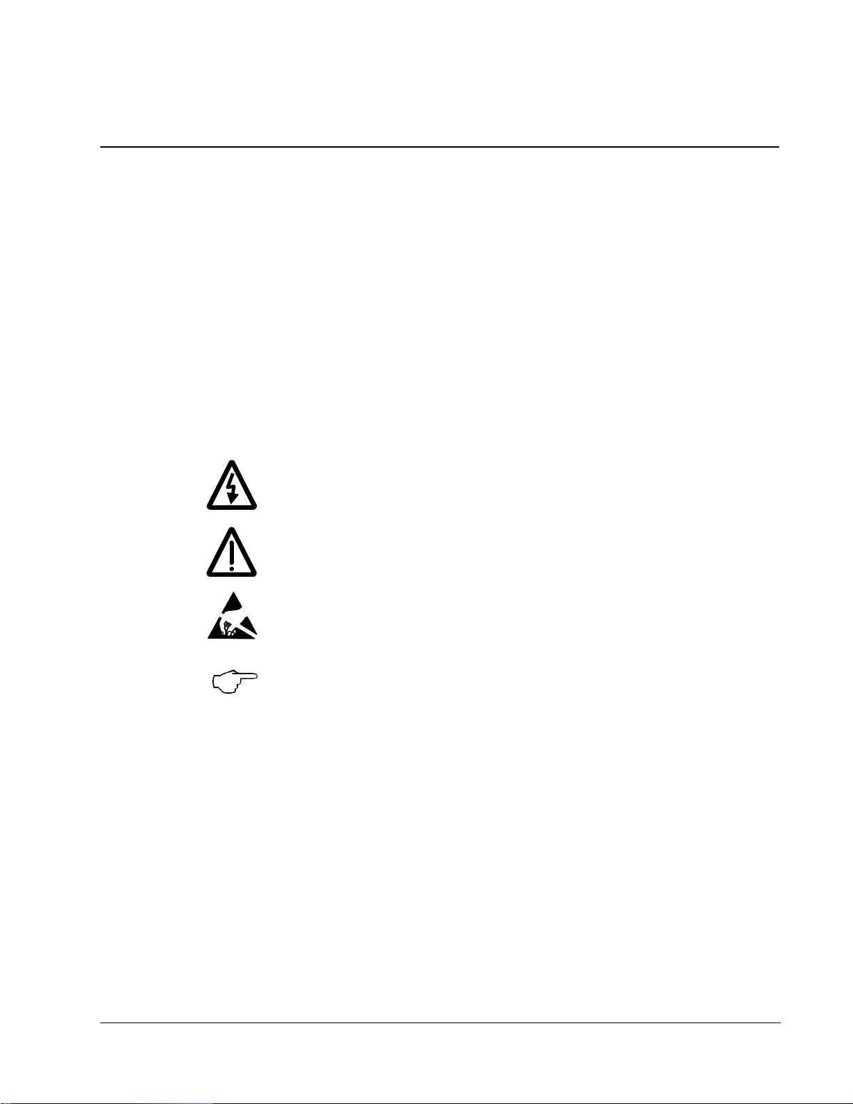
subject. The warning symbols are used as follows:
5
Dangerous voltage warning warns of high voltage which can cause
physical injury and/or damage to the equipment.
General warning warns about conditions, other than those caused by
electricity, which can result in physical injury and/or damage to the
equipment.
Electrostatic discharge warning warns of electrost atic discharge which
can damage the equipment.
Special note or recommendation. This symbol is used to highlight
especially important information or recommendation for product
application.
Safety Instructions
Page 6

6
Installation and Maintenance Work
These warnings are intended for all who work on the drive, motor cable or motor.
Ignoring the instructions can cause physical injury or death.
WARNING!
• Only qualified electricians are allowed to install and maintain the drive.
• Never work on the drive, motor cable or motor when main power is applied.
After switching off the power, always wait for 5 minutes to let the intermediate
circuit capacitors discharge before you start working on the drive, the motor or
the motor cable.
Always ensure by measuring with a multimeter (impedance at least 1 Mohm)
that:
1.Voltage between drive input phases L1, L2 and L3 and the frame is close to
0 V.
2.Voltage between terminals UDC+ and UDC- and the frame is close to 0 V.
Do not work on the control cables when power is applied to the drive or to the
•
external control circuits. Externally supplied control circuits may cause
dangerous voltages inside the drive even when the main power on the drive is
switched off.
Do not make any insulation or voltage withstand tests on the drive or drive
•
modules.
When reconnecting the motor cable, always check that the phase order is
•
correct.
Note:
The disconnecting device (means) of the drive does not isolate the input cables
•
and busbars from the main AC supply. Before working inside the cabinet,
isolate the input cables and busbars from the main supply with the
disconnecting device at the distribution board or with the disconnector of the
supply transformer.
The motor cable terminals on the drive are at a dangerously high volt ag e whe n
•
the input power is on, regardless of whether the motor is running or not.
The brake control terminals (UDC+, UDC-, R+ and R- terminals) carry a
•
dangerous DC voltage (over 500 V).
Depending on the external wiring, dangerous voltages [115 V, 220 V or 230 V]
•
may be present on the terminals of relay outputs RO1 to RO3.
The Prevention of Unexpected S t art function does not remove the vo lt age from
•
the main and auxiliary circuits.
Safety Instructions
Page 7

WARNING!
• Cover the drive when installing to ensure that dust from drilling or foreign
objects do not enter the drive. Electrically conductive dust inside the unit may
cause damage or lead to malfunction.
Ensure sufficient cooling.
•
Welding of the cabinet frame is not recommended. However, if electric welding
•
is the only way to mount the cabinet, follow the instructions given in chapter
"Mechanical Installation". Ensure that welding fumes are not inhaled. If the
welding return wire is connected improperly, the welding circuit may damage
electronic circuits in the cabinet.
When removing the module from the cabinet and manoeuvring it outside the
•
cabinet, prevent it from toppling over by securing it. The drive module is heavy
and has a high center of gravity.
7
WARNING! The printed circuit boards contain components sensitive to electrostatic
discharge. Wear a grounding wrist band when handling the boards. Do not touch the
boards unnecessarily.
Safety Instructions
Page 8
8
Grounding
These instructions are intended for all who are responsible for the grounding of the
drive. Incorrect grounding can cause physical injury, death or equipment malfunction
and increase electromagnetic interference.
WARNING!
• Ground the drive, the motor and adjoining equipment to ensure personnel
safety in all circumstances, and to reduce electromagnetic emission and pickup.
Make sure that grounding conductors are adequately sized as required by
•
safety regulations.
In a multiple-drive installation, connect each drive separately to protective
•
earth (PE).
Do not install a drive with EMC filter option +E202 on an ungrounded power
•
system or a high resistance-grounded (over 30 ohms) power system.
Note:
Power cable shields are suitable for equipment grounding conductors only
•
when adequately sized to meet safety regulations.
As the normal leakage current of the drive is higher than 3.5 mA AC or 10 mA
•
DC (stated by EN 50178, 5.2.11.1), a fixed protective earth connection is
required.
Fiber Optic Cables
WARNING! Handle the fibre optic cables with care. When unplugging optic cables,
always grab the connector, not the cable itself. Do not touch the ends of the fibres
with bare hands as the fibre is extremely sensitive to dirt. The minimum allowed
bend radius is 35 mm (1.4 in.).
Safety Instructions
Page 9
Operation
These warnings are intended for all who plan the operation of the drive or operate
the drive. Ignoring the instructions can cause physical injury or death or damage the
equipment.
WARNING!
• Before adjusting the drive and putting it into service, make sure that the motor
and all driven equipment are suitable for operation throughout the speed range
provided by the drive. The drive can be adjusted to operate the motor at
speeds above and below the speed provided by connecting the motor directly
to the power line.
Do not activate automatic fault reset functions of the Standard Application
•
Program if dangerous situations can occur. When activated, these functions
will reset the drive and resume operation after a fault.
Do not control the motor with the disconnecting device (disconnecting means);
•
instead, use the control panel keys and , or commands via the I/O
board of the drive. The maximum allowed number of charging cycles of the DC
capacitors (i.e. power-ups by applying power) is five in ten minutes.
9
Do not use the optional Prevention of Unexpected Start function for stopping
•
the drive when the drive is running. Give a Stop command instead.
Note:
If an external source for start command is selected and it is ON, the drive (with
•
St andard Application Program) will start immediately after fault reset unle ss the
drive is configured for 3-wire (a pulse) start/stop.
When the control location is not set to Local (L not shown in the status row of
•
the display), the stop key on the control panel will not stop the drive. To stop
the drive using the control panel, press the LOC/REM key and then the stop
key .
Safety Instructions
Page 10

10
Permanent Magnet Motor
These are additional warnings concerning permanent magnet motor drives.
WARNING! Do not work on the dr ive when the perma nent magnet mo tor is rot ating.
Also, when the supply power is switched off and the inverter is stopped, a rotating
permanent magnet motor feeds power to the intermediate circuit of the drive and the
supply connections become live.
Installation and Maintenance Work
Before installation and maintenance work on the drive:
• Disconnect the motor from the drive with a safety switch
and additionally if possible (or)
• lock the motor shaft and ground the motor connection terminals temporarily by
connecting them together as well as to the PE. Before grounding, measure that
the motor is de-energized.
Operation
Do not run the motor over the rated speed. Motor overspeed leads to overvoltage
which may explode the capacitors in the intermediate circuit of the drive.
Safety Instructions
Page 11

Table of Contents
Safety Instructions
What this Chapter Contains . . . . . . . . . . . . . . . . . . . . . . . . . . . . . . . . . . . . . . . . 5
Use of Warnings and Notes . . . . . . . . . . . . . . . . . . . . . . . . . . . . . . . . . . . . . . . . 5
Installation and Maintenance Work . . . . . . . . . . . . . . . . . . . . . . . . . . . . . . . . . . 6
Operation . . . . . . . . . . . . . . . . . . . . . . . . . . . . . . . . . . . . . . . . . . . . . . . . . . . . . . 9
Permanent Magnet Motor . . . . . . . . . . . . . . . . . . . . . . . . . . . . . . . . . . . . . . . . . 10
Table of Contents
About this Manual
What this Chapter Contains . . . . . . . . . . . . . . . . . . . . . . . . . . . . . . . . . . . . . . . 14
Target Audience . . . . . . . . . . . . . . . . . . . . . . . . . . . . . . . . . . . . . . . . . . . . . . . . 14
Common Chapters for Products . . . . . . . . . . . . . . . . . . . . . . . . . . . . . . . . . . . . 14
Categorization According to the Frame Size . . . . . . . . . . . . . . . . . . . . . . . . . . 14
Categorization According to the + Code . . . . . . . . . . . . . . . . . . . . . . . . . . . . . 14
Contents . . . . . . . . . . . . . . . . . . . . . . . . . . . . . . . . . . . . . . . . . . . . . . . . . . . . . . 15
Installation and Commissioning Flowchart . . . . . . . . . . . . . . . . . . . . . . . . . . . . 16
Inquiries . . . . . . . . . . . . . . . . . . . . . . . . . . . . . . . . . . . . . . . . . . . . . . . . . . . . . . 17
11
The ACS800-PC
What this Chapter Contains . . . . . . . . . . . . . . . . . . . . . . . . . . . . . . . . . . . . . . . 18
The ACS800-PC . . . . . . . . . . . . . . . . . . . . . . . . . . . . . . . . . . . . . . . . . . . . . . . . 18
Type Code . . . . . . . . . . . . . . . . . . . . . . . . . . . . . . . . . . . . . . . . . . . . . . . . . . . . 19
Product Ordering — Special Note . . . . . . . . . . . . . . . . . . . . . . . . . . . . . . . . . . 20
Main Circuit and Control . . . . . . . . . . . . . . . . . . . . . . . . . . . . . . . . . . . . . . . . . . 20
Mechanical Installation
What this Chapter Contains . . . . . . . . . . . . . . . . . . . . . . . . . . . . . . . . . . . . . . . 23
Moving the Unit . . . . . . . . . . . . . . . . . . . . . . . . . . . . . . . . . . . . . . . . . . . . . . . . 23
Before Installation . . . . . . . . . . . . . . . . . . . . . . . . . . . . . . . . . . . . . . . . . . . . . . . 24
Fastening the Cabinet to the Floor and Wall . . . . . . . . . . . . . . . . . . . . . . . . . . 26
Electric Welding . . . . . . . . . . . . . . . . . . . . . . . . . . . . . . . . . . . . . . . . . . . . . . . . 28
Planning the Electrical Installation
What this Chapter Contains . . . . . . . . . . . . . . . . . . . . . . . . . . . . . . . . . . . . . . . 29
To Which Products this Chapter Applies . . . . . . . . . . . . . . . . . . . . . . . . . . . . . 29
Motor Selection and Compatibility . . . . . . . . . . . . . . . . . . . . . . . . . . . . . . . . . . 29
Permanent Magnet Synchronous Motor . . . . . . . . . . . . . . . . . . . . . . . . . . . . . . 33
Supply Connection . . . . . . . . . . . . . . . . . . . . . . . . . . . . . . . . . . . . . . . . . . . . . . 33
Table of Contents
Page 12

12
Thermal Overload and Short-Circuit Protection . . . . . . . . . . . . . . . . . . . . . . . .34
Ground Fault Protection . . . . . . . . . . . . . . . . . . . . . . . . . . . . . . . . . . . . . . . . . .34
Emergency Stop Devices . . . . . . . . . . . . . . . . . . . . . . . . . . . . . . . . . . . . . . . . .35
Prevention of Unexpected Start (ACS800-07/U7 only) . . . . . . . . . . . . . . . . . . .36
Selecting the Power Cables . . . . . . . . . . . . . . . . . . . . . . . . . . . . . . . . . . . . . . .37
Power Factor Compensation Capacitors . . . . . . . . . . . . . . . . . . . . . . . . . . . . . .39
Equipment Connected to the Motor Cable . . . . . . . . . . . . . . . . . . . . . . . . . . . .40
Protecting the Relay Output Contacts and Attenuating
Disturbances in Case of Inductive Loads . . . . . . . . . . . . . . . . . . . . . . . . . . . . .41
Selecting the Control Cables . . . . . . . . . . . . . . . . . . . . . . . . . . . . . . . . . . . . . . .42
Connection of a Motor Temperature Sensor to the Drive I/O . . . . . . . . . . . . . . 43
Routing the Cables . . . . . . . . . . . . . . . . . . . . . . . . . . . . . . . . . . . . . . . . . . . . . .43
Electrical Installation
What this Chapter Contains . . . . . . . . . . . . . . . . . . . . . . . . . . . . . . . . . . . . . . .45
Before Installation . . . . . . . . . . . . . . . . . . . . . . . . . . . . . . . . . . . . . . . . . . . . . . .45
Checking the Insulation of the Assembly . . . . . . . . . . . . . . . . . . . . . . . . . . . . .46
Warning Sticker . . . . . . . . . . . . . . . . . . . . . . . . . . . . . . . . . . . . . . . . . . . . . . . . .46
Example Wiring Diagram . . . . . . . . . . . . . . . . . . . . . . . . . . . . . . . . . . . . . . . . . .47
Power Cable Connection Diagram . . . . . . . . . . . . . . . . . . . . . . . . . . . . . . . . . .48
Connecting the Power Cables . . . . . . . . . . . . . . . . . . . . . . . . . . . . . . . . . . . . . .49
Connecting the Control Cables . . . . . . . . . . . . . . . . . . . . . . . . . . . . . . . . . . . . .50
Installation of Optional Modules . . . . . . . . . . . . . . . . . . . . . . . . . . . . . . . . . . . .52
Layout Drawing of Factory Installed Optional Equipment . . . . . . . . . . . . . . . . .54
Motor Control and I/O Board (RMIO)
What this Chapter Contains . . . . . . . . . . . . . . . . . . . . . . . . . . . . . . . . . . . . . . .55
To Which Products this Chapter Applies . . . . . . . . . . . . . . . . . . . . . . . . . . . . . .55
Note for the ACS800-02 with Enclosure Extension, ACS800-07/U7, and
ACS800-PC . . . . . . . . . . . . . . . . . . . . . . . . . . . . . . . . . . . . . . . . . . . . . . . . . . . .55
Note on External Power Supply . . . . . . . . . . . . . . . . . . . . . . . . . . . . . . . . . . . .55
RMIO board specifications . . . . . . . . . . . . . . . . . . . . . . . . . . . . . . . . . . . . . . . .57
Installation Checklist and Start-Up
Checklist . . . . . . . . . . . . . . . . . . . . . . . . . . . . . . . . . . . . . . . . . . . . . . . . . . . . . .60
Start-Up Procedure . . . . . . . . . . . . . . . . . . . . . . . . . . . . . . . . . . . . . . . . . . . . . .61
Maintenance
What this Chapter Contains . . . . . . . . . . . . . . . . . . . . . . . . . . . . . . . . . . . . . . .62
Safety . . . . . . . . . . . . . . . . . . . . . . . . . . . . . . . . . . . . . . . . . . . . . . . . . . . . . . . .62
Maintenance Intervals . . . . . . . . . . . . . . . . . . . . . . . . . . . . . . . . . . . . . . . . . . . .62
Air Filter Material . . . . . . . . . . . . . . . . . . . . . . . . . . . . . . . . . . . . . . . . . . . . . . . .62
Checking and Replacing the Air Filters . . . . . . . . . . . . . . . . . . . . . . . . . . . . . . .63
Exhaust Filter for UL Type 12 . . . . . . . . . . . . . . . . . . . . . . . . . . . . . . . . . . . . . .66
Heatsink . . . . . . . . . . . . . . . . . . . . . . . . . . . . . . . . . . . . . . . . . . . . . . . . . . . . . .68
Table of Contents
Page 13

Fans . . . . . . . . . . . . . . . . . . . . . . . . . . . . . . . . . . . . . . . . . . . . . . . . . . . . . . . . . 68
Replacing the Cabinet Fan . . . . . . . . . . . . . . . . . . . . . . . . . . . . . . . . . . . . . . . . 69
Layout of the Drive Module . . . . . . . . . . . . . . . . . . . . . . . . . . . . . . . . . . . . . . . 72
Capacitors . . . . . . . . . . . . . . . . . . . . . . . . . . . . . . . . . . . . . . . . . . . . . . . . . . . . 75
Replacing the Drive Module . . . . . . . . . . . . . . . . . . . . . . . . . . . . . . . . . . . . . . . 77
LEDs . . . . . . . . . . . . . . . . . . . . . . . . . . . . . . . . . . . . . . . . . . . . . . . . . . . . . . . . . 80
Technical Data
What this Chapter Contains . . . . . . . . . . . . . . . . . . . . . . . . . . . . . . . . . . . . . . . 81
Free Space Around the Unit . . . . . . . . . . . . . . . . . . . . . . . . . . . . . . . . . . . . . . 87
Input Power Connection . . . . . . . . . . . . . . . . . . . . . . . . . . . . . . . . . . . . . . . . . . 88
Motor Connection . . . . . . . . . . . . . . . . . . . . . . . . . . . . . . . . . . . . . . . . . . . . . . . 88
Efficiency . . . . . . . . . . . . . . . . . . . . . . . . . . . . . . . . . . . . . . . . . . . . . . . . . . . . . 88
Cooling . . . . . . . . . . . . . . . . . . . . . . . . . . . . . . . . . . . . . . . . . . . . . . . . . . . . . . . 89
Degrees of Protection . . . . . . . . . . . . . . . . . . . . . . . . . . . . . . . . . . . . . . . . . . . . 89
Ambient Conditions . . . . . . . . . . . . . . . . . . . . . . . . . . . . . . . . . . . . . . . . . . . . . 89
Materials . . . . . . . . . . . . . . . . . . . . . . . . . . . . . . . . . . . . . . . . . . . . . . . . . . . . . . 90
Applicable Standards . . . . . . . . . . . . . . . . . . . . . . . . . . . . . . . . . . . . . . . . . . . . 90
CE Marking . . . . . . . . . . . . . . . . . . . . . . . . . . . . . . . . . . . . . . . . . . . . . . . . . . . . 91
Equipment Warranty and Liability . . . . . . . . . . . . . . . . . . . . . . . . . . . . . . . . . . . 92
13
Dimensional Drawings
Resistor Braking
What this Chapter Contains . . . . . . . . . . . . . . . . . . . . . . . . . . . . . . . . . . . . . . . 95
To Which Products this Chapter Applies . . . . . . . . . . . . . . . . . . . . . . . . . . . . . 95
Availability of Brake Choppers and Resistors for the ACS800 . . . . . . . . . . . . . 95
How to Select the Correct Drive/Chopper/Resistor Combination . . . . . . . . . . . 95
Optional Brake Chopper and Resistor(s) for the ACS800-U2, ACS800-U4,
ACS800-PC and ACS800-07/U7 . . . . . . . . . . . . . . . . . . . . . . . . . . . . . . . . . . . 96
Resistor Installation and Wiring . . . . . . . . . . . . . . . . . . . . . . . . . . . . . . . . . . . . 96
Protection of Frame Sizes R7 and R8 (ACS800-U2, ACS800-U4,
ACS800-PC, ACS800-U7/07) . . . . . . . . . . . . . . . . . . . . . . . . . . . . . . . . . . . . . 97
Brake Circuit Commissioning . . . . . . . . . . . . . . . . . . . . . . . . . . . . . . . . . . . . . . 98
Table of Contents
Page 14

14
About this Manual
What this Chapter Contains
This chapter describes the intended audience and contents of the manual. It
contains a flowchart of steps in checking the delivery, installing and commissioning
the drive. The flowchart refers to chapters/sections in this manual and other
manuals.
Target Audience
This manual is intended for people who plan the installation, install, commission, use
and service the drive. Read the manual before working on the drive. The reader is
expected to know the fundamentals of electricity, wiring, electrical components and
electrical schematic symbols.
The manual is written for readers worldwide. Both SI and imperial units are shown.
Special US instructions for installations within the United States that must be
performed per the National Electrical Code and local codes are marked with (US).
Common Chapters for Products
Chapters "Planning the Electrical Installation", "Motor Control and I/O Board (RMIO)"
and "Resistor Braking" apply to the ACS800-01/U1, ACS800-02/U2, ACS800-04/U4,
ACS800-07/U7, and ASC800-PC.
Categorization According to the Frame Size
Some instructions, technical data and dimensional drawings which concern only
certain frame sizes are marked with the symbol of the frame size R2, R3... or R8.
The frame size is not marked on the drive designation label. To identify the frame
size of your drive, see the rating tables in chapter
Categorization According to the + Code
The instructions, technical data and dimensional drawings which concern only
certain optional selections are marked with + codes, e.g. +E205. The options
included in the drive can be identified from the +
designation label of the drive. The + code selections are listed in chapter
ACS800-PC" under "Type Code".
"Technical Data".
codes visible on the type
"The
About this Manual
Page 15

Contents
15
The chapters of this manual are briefly described below.
"Safety Instructions" give safety instructions for the installation, commissioning,
operation and maintenance of the drive.
"About this Manual" introduces this manual.
"The ACS800-PC" describes the drive.
"Mechanical Installation" shows how to move and unpack the delivery and how to
fasten the cabinet to the floor.
"Planning the Electrical Installation" instructs on the motor and cable selection, the
protections and the cable routing.
"Electrical Installation" instructs how to wire the drive.
"Motor Control and I/O Board (RMIO)" shows external control connections to the
motor control and I/O board and its specifications.
"Installation Checklist and Start-Up" helps in checking the mechanical and electrical
installation of the drive.
"Maintenance" contains preventive maintenance instructions.
"Technical Data" contains the technical specifications of the drive, e.g. the ratings,
sizes and technical requirements, provisions for fulfilling the requirements for CE
and other markings and warranty policy.
"Dimensional Drawings" contains the dimensional drawings of the drive.
"Resistor Braking" describes how to select, protect and wire optional brake choppers
and resistors. The chapter also contains technical data.
About this Manual
Page 16
16
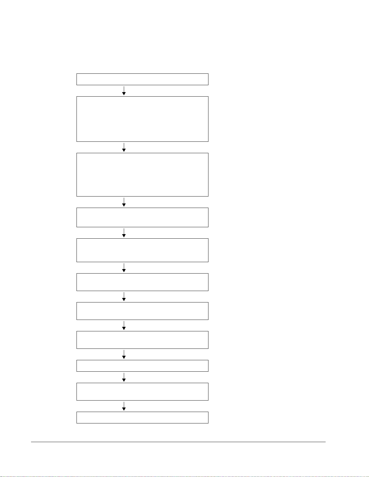
Installation and Commissioning Flowchart
Task See
Identify the frame size of your drive: R7 or R8. “Technical Data / NEMA Ratings”
Plan the installation.
Check the ambient conditions, ratings, required
cooling air flow, input power connection,
compatibility of the motor, motor connection, and
other technical data.
Select the cables.
Unpack and check the unit.
Check that all necessary optional modules and
equipment are present and correct.
Only intact units may be started up.
Check the installation site. “Mechanical Installation: Before Installation”
If the drive is about to be connected to an IT
(ungrounded) system, check that the drive is not
equipped with EMC filter +E202.
"Technical Data"
"Planning the Electrical Installation"
Option manual (if optional equipment is
included)
“Mechanical Installation: Moving the Unit,
Before Installation”
If the converter has been non-operational for
more than one year, the converter DC link
capacitors need to be reformed. Ask ABB for
instructions.
"Technical Data"
“The ACS800-PC: Type Code.” For
instructions on how to disconnect the EMC
filtering, contact ABB.
About this Manual
Route the cables. “Planning the Electrical Installation: Routing
the Cables”
Check the insulation of the motor and the motor
cable.
Install the drive. Connect the power cables. Connect
the control and the auxiliary control cables.
Check the installation. "Installation Checklist and Start-Up"
Commission the drive. "Installation Checklist and Start-Up",
Commission the optional brake chopper (if present). "Resistor Braking"
“Electrical Installation: Checking the Insulation
of the Assembly “
“Mechanical Installation, Electrical Installation,
Resistor Braking” (optional)
appropriate firmware manual
Page 17

Inquiries
17
Address any inquiries about the product to the local ABB representative, quoting the
type code and the serial number of the unit. If the local ABB representative cannot
be contacted, address inquiries to the manufacturing facility.
About this Manual
Page 18
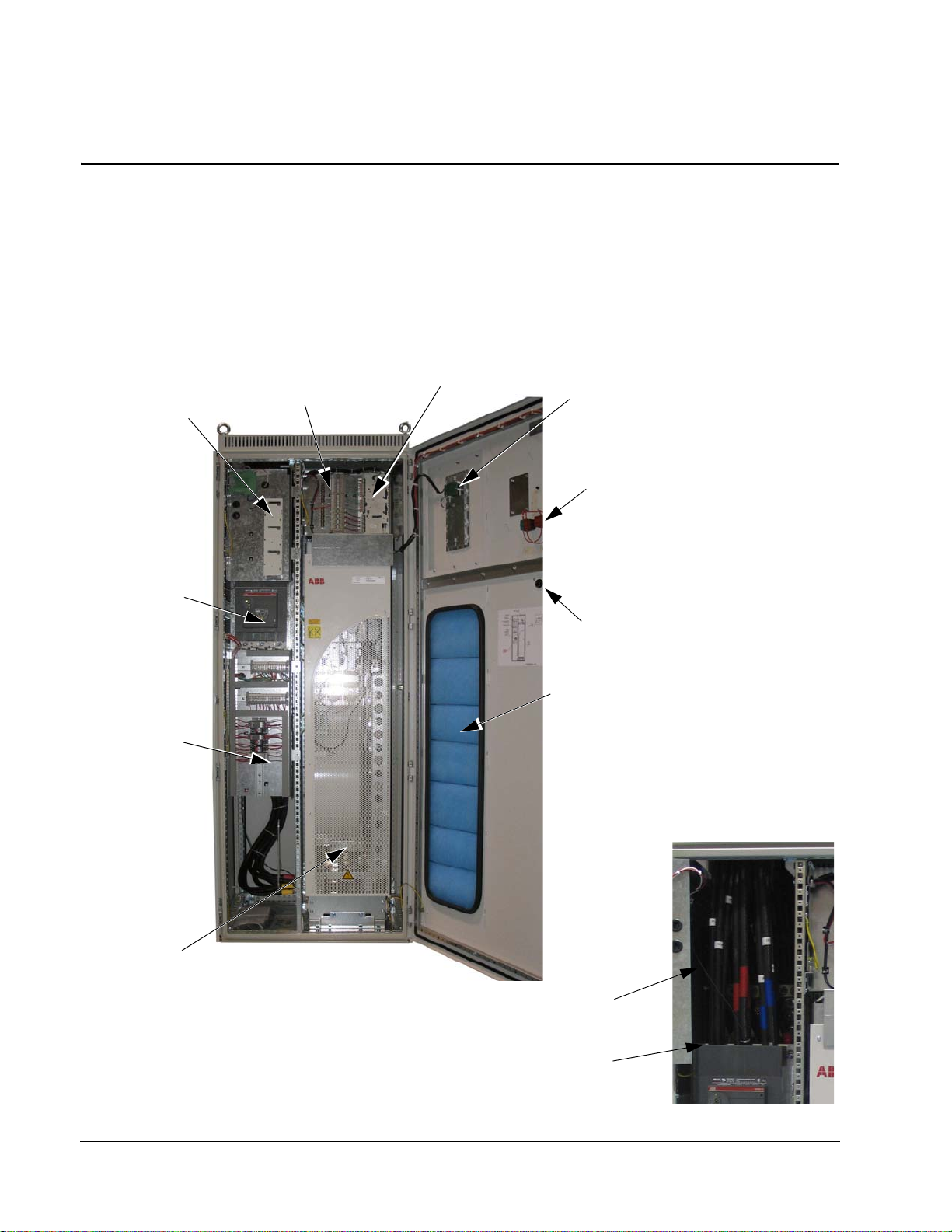
18
Control Panel
* Emergency Stop
Drive Control Unit
RDCU (RMIO)
Switch Handle
Circuit Breaker
* Cabinet Filter
Drive Module
Swing frame
with options
Circuit Breaker
I/O Expansion
AIMA-01 and
swing frame
Output Connections
Install before input
power cables
Input Power Cable
directly to Circuit
Breaker
Fuses are located
behind the control
unit
The ACS800-PC
What this Chapter Contains
This chapter describes the construction and operating principle of the drive in short.
The ACS800-PC
The ACS800-PC is a cabinet-installed drive for controlling AC motors.
The ACS800-PC
Page 19

Type Code
19
The type code contains information on the specifications and configuration of the
drive. The first digits from left express the basic configuration (e.g. ACS800-PC0170-5). The optional selections are given thereafter, separated by + signs (e.g.
+E202). The main selections are described below . Not all selections are availa ble for
all types. For more information, refer to ACS800 Ordering Information (EN code:
64556568, available on request).
Selection Alternatives
Product series ACS800 product series
Type PC cabinet built (USA). When no options are selected: 6-pulse diode
bridge, UL type 1, circuit breaker with class T/L fuses, control panel
CDP312R, US version of the Standard Application Program (threewire start/stop as default setting), cable conduit entry, common
mode filter in frame size R8, 2nd Environment EMC filter in frame
R8, boards with coating, one set of manuals.
Size Refer to Technical Data: NEMA Ratings.
Voltage range
(nominal rating in
bold)
+ options
Degree of protection B054 UL type 1 with filter
Resistor braking D150 brake chopper (external resistor)
Line options F250 line contactor
Cabinet options G313 output for motor heater (external supply)
Cabling Only top entry and exit
Fieldbus K… Refer to ACS800 Ordering Information (EN code: 64556568).
I/O L504 additional terminal block X2
Starter for auxiliary
motor fan
Application program N… Refer to ACS800 Ordering Information (EN code: 64556568).
Safety features Q950 prevention of unexpected start
5 460/480/500 VAC
7 525/575/600/690 VAC
B055 UL type 12
L505 thermistor relay (1 or 2 pcs) (Not when +L506)
L506 Pt100 relay (3 pcs) (Not when +L505)
L515 I/O Extension Adapter
L… Refer to ACS800 Ordering Information (EN code: 64556568).
M600 1…1.6 A
M601 1.6…2.5 A
M602 2.5…4 A
M603 4…6.3 A
M604 6.3…10 A
M605 10…16 A
Q951 emergency stop of category 0 (+F250 required)
The ACS800-PC
Page 20
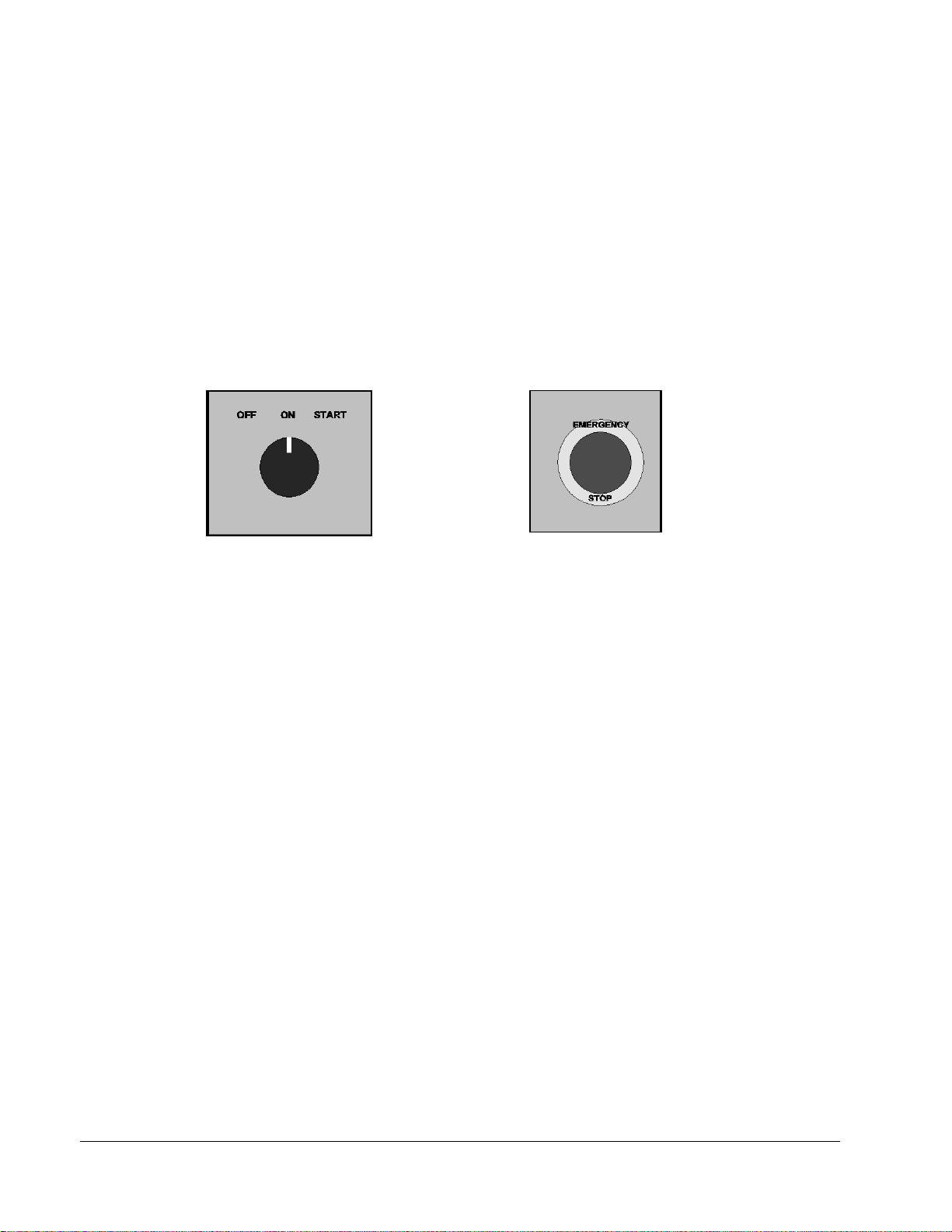
20
Emergency stop button
(optional)
Operating switch (units with main
contactor only)
“START” position closes the main
contactor; “ON” position keeps the main
contactor closed; “OFF” position opens
the main contactor.
Product Ordering — Special Note
The ACS800-PC-0170-5 through -0440-5 are available with UL Type 1 and UL Type
12. The ACS800-PC-0490-5 through -0610-5 are available with UL Type 12. These
units are always supplied with exha ust fan an d are not available without th e exhaust
fan.
Main Circuit and Control
Door Switches
The following switches are mounted on the cabinet door when option F250+Q951 is
included:
The ACS800-PC
Page 21
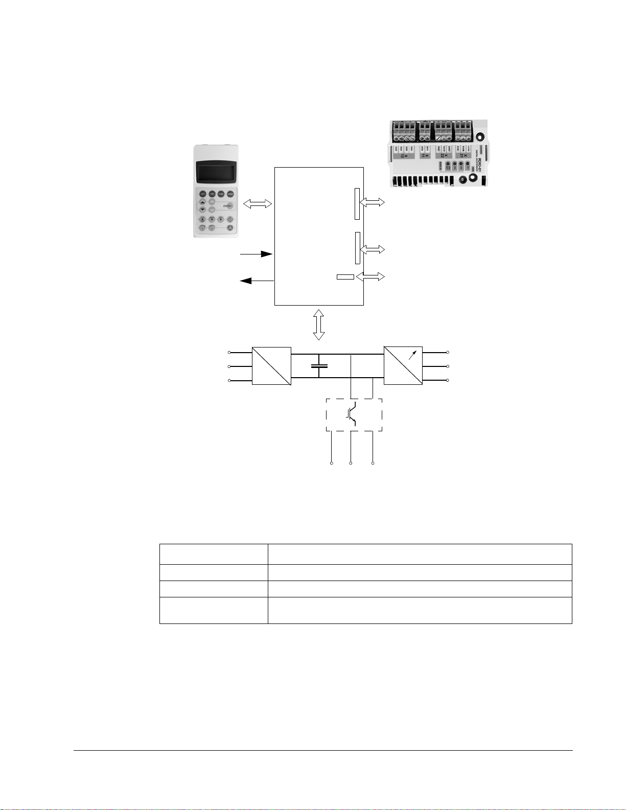
Diagram
~
=
~
=
Motor
control and
I/O board
(RMIO)
External control via
analogue/digital
inputs and outputs
Input power
Output power
R- UDC+ UDC-
R+
Optional module 1: RMBA, RAIO,
RDIO, RDNA, RPBA, RCNA, RMBP,
RETA or RTAC
Optional module 2: RTAC, RAIO or
RDIO
DDCS communication option module:
RDCO-01, RDCO-02 or RDCO-03
Brake chopper (optional)
This diagram shows the control interfaces and the main circuit of the drive.
21
by switching the IGBTs.
Operation
This table describes the operation of the main circuit in short.
Component Description
The ACS800-PC
six-pulse rectifier converts the three-phase AC voltage to DC voltage
capacitor bank energy storage which stabilizes the intermediate circuit DC voltage
six-pulse IGBT inverter converts the DC voltage to AC voltage. The motor operation is controlled
Page 22

22
Printed Circuit Boards
The drive contains the following printed circuit boards as standard:
• Main circuit board (AINT)
• Motor control and I/O board (RMIO) with a fibre optic link to the AINT board
• Input bridge control board (AINP)
• Input bridge protection board (AIBP) which includes varistors and snubbers for
the thyristors
• Power supply board (APOW)
• Gate driver control board (AGDR)
• Diagnostics and panel interface board (ADPI)
• Brake chopper control board (ABRC) with option +D150
Motor Control
The motor control is based on the Direct Torque Control (DTC) method. Two phase
currents and DC link voltage are measured and used for the control. The third phase
current is measured for earth fault protection.
The ACS800-PC
Page 23
Mechanical Installation
) Max 30
What this Chapter Contains
This chapter describes the mechanical installation procedure of the drive.
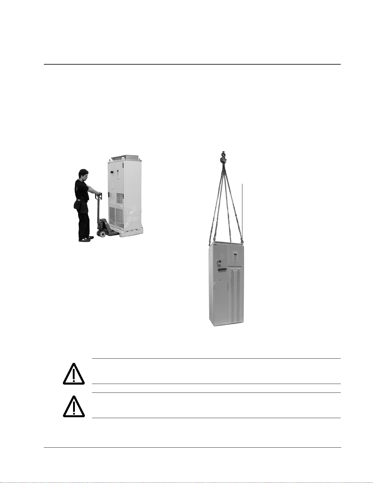
Moving the Unit
Move the transport package by truck and pallet truck to the installation site.
23
WARNING! The ACS800-PC is to be handled and shipped standing up ONLY. This
unit is not designed to be laid on its back.
WARNING! Lif t the drive by the upper part only using the lif ting lugs/bars att ached to
the top of the unit.
Mechanical Installation
Page 24

24
Type designation label
Before Installation
Check for external damage. If damage exists, immediately document, contact the shipper
and contact ABB.
Delivery Check
The drive delivery contains:
• Drive cabinet including factory installed options such as optional modules
(inserted onto the RMIO board in the RDCU unit)
• Residual voltage warning stickers
• Hardware manual
• Appropriate firmware manuals and guides
• Appropriate optional module manuals
• Delivery documents.
Check that there are no signs of damage. Before attempting installation and
operation, check the information on the type designation label of the drive to verify
that the unit is of the correct type. The label includes a NEMA rating, a typ e code and
a serial number which allow individual recognition of each unit. The first digit of the
serial number refers to the manufacturing plant. The next four digits refer to the unit’s
manufacturing year and week respectively. The remaining digits complete the serial
number so that there are no two units with the same serial number.
The type designation label is located on the inside of the front cover. UL and cUL
listing marks are shown on a seperate label.
Input 3PH 48...63Hz
Voltage(U1) 380..500 Vac
Current(I1n) 498 A
Short Circuit 100kA
Output 3PH 0...300 Hz
Voltage(U2) 0...U1 Vac
Current(I2n) 515 A
Power(Pn) 400 Hp
Schematic: 3AUA0000011083
ACS800-PC-0400-5+B055+K454+L503+L504+L505+M603
ABB Inc.
Made in USA of foreign parts
Mfg. Date: 06-August-2008 Orig. Firmware: ASXR734U
S/N 2083201813
Requirements for the Installation Site
Check the installation site according to the requirements below. Refer to
ACS800-PC Dimensional Drawings for frame details. See
"Technical Data" for the
allowed operation conditions of the drive.
Mechanical Installation
Page 25

Cooling Air Flow
Provide the drive with the amount of clean cooling air given in "Technical Data" /
"NEMA Ratings".
Enclosure Ratings
NEMA 1 (NEMA Standard 7-15-1991)
Type 1 enclosures are intended for indoor use primarily to provided a degree of
protection against limited amounts of falling dirt.
UL Type 1 (ANSI/UL50)
Indoor use primarily to provide protection against contact with the enclosed
equipment and against a limited amount of falling dirt.
Recommendation
NEMA 1 / UL Type 1 enclosures should be applied to clean environments without
circulating dust or other contaminants that may collect on surfaces. Equipment of
this enclosure rating should be applied to clean electrical room or installed in another
enclosure with higher degree of protection. NEMA 1 / UL T ype 1 enclosures typically
are not the best selection for installation on industrial factory floors.
25
NEMA 12 (NEMA Standard 7-15-1991)
Type 12 enclosures are intended for indoor use primarily to provide a degree of
protection against circulating dust, falling dirt, and dripping noncorrosive liquids.
UL Type 12 (ANSI/UL50)
Indoor use to provide a degree of protection against dust, dirt, fiber flyings, dripping
water, and external condensation of noncorrosive liquids.
Recommendation
NEMA 12 / UL Type 12 enclosures should be used in environments that contain
circulating dust or other contaminant particles. NEMA 12 / UL Type 12 enclosures
are recommended for most applications in industrial factory floor where dust is
present but spraying liquids are not.
Regular preventative maintenance of filter changing or cleaning is required. Inspect
the enclosure and installed equipment for dust or particle build up that may limit
cooling, clean as needed.
Mechanical Installation
Page 26
26
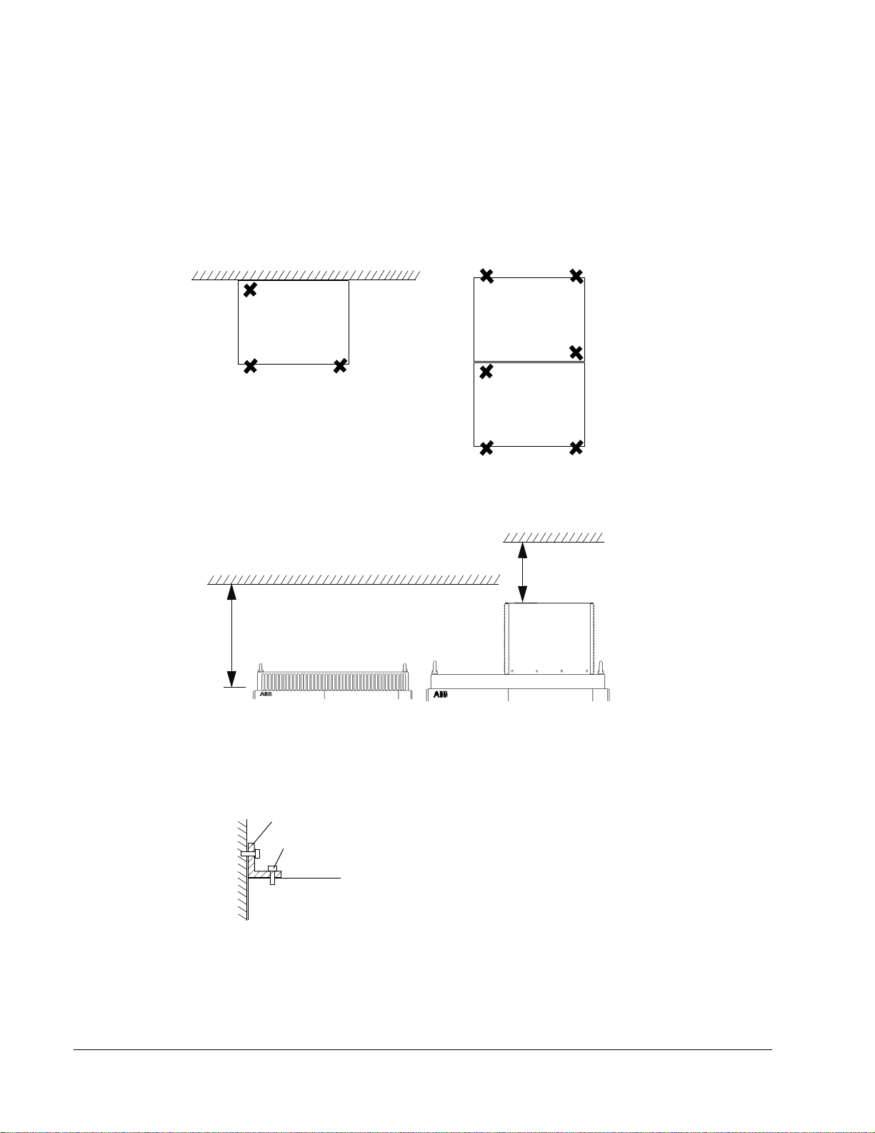
Fastening points when installed
back against wall
Fastening points when installed
back against back
Cabinet top
M12 bolt
L-bracket
Fastening the cabinet at the top
by using L-brackets (side view)
Top clearance
UL Type 12UL Type 1
15 in.
12 in. for fan replacement
Fastening the Cabinet to the Floor and Wall
Fasten the cabinet to the floor with the fastening holes inside the cabinet. When
fastening at the back is not possible, fasten the cabinet at the top using L-brackets
bolted to the holes of the lifting lugs (M12 bolt). The cabinet can be fastened against
a wall or back to back with another cabinet. Refer to
horizontal and vertical fastening points. Height adjustment can be done by using
metal shims between the bottom frame and floor.
"Dimensional Drawings" for the
Mechanical Installation
Page 27
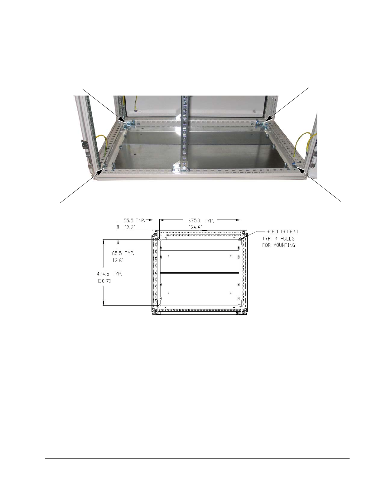
Fastening the Cabinet Through the Holes Inside the Cabinet
Fastening bolt: M12 (1/2" to 9/16")
Bottom View
The cabinet can be fastened to the floor using the fastening holes inside the cabinet.
The maximum allowed distance between the fastening points is 800 mm (31.50 in.).
27
Mechanical Installation
Page 28

28
Electric Welding
It is not recommended to fasten the cabinet by welding.
Cabinets without flat bars at the base
If the preferred fastening methods (clamping or bolting through the holes inside the
cabinet) cannot be used, proceed as follows:
• Connect the return conductor of the welding equipment to the cabinet frame at
the bottom within 0.5 metres of the welding point.
WARNING! If the welding return wire is connected improperly, the welding circuit
may damage electronic circuits in the cabinet. The thickness of the zinc coating of
the cabinet frame is 100 to 200 micrometres; on the flat bars the coating is
approximately 20 micrometers. Ensure that the welding fumes are not inhaled.
Mechanical Installation
Page 29

Planning the Electrical Installation
What this Chapter Contains
This chapter contains the instructions that you must follow when selecting the mot or,
cables, protections, cable routing and way of operation for the drive system. Always
follow local regulations.
Note: If the recommendations given by ABB are not followed, the drive may
experience problems that the warranty does not cover.
To Which Products this Chapter Applies
This chapter applies to the ACS800-01/U1, ACS800-02/U2, ACS800-04/U4,
ACS800-PC, and ACS800-07/U7 types up to -0610-X.
29
Motor Selection and Compatibility
1. Select the motor according to the rating tables in chapter Technical Data. Use the
DriveSize PC tool if the default load cycles are not applicable.
2. Check that the motor ratings lie within the allowed ranges of the drive control
program:
• Motor nominal voltage is 1/2 … 2 · UN of the drive
• Motor nominal current is 1/6 … 2 · I
0 … 2 · I
3. Check that the motor voltage rating meets the application requirements:
• The motor voltage is selected according to the AC voltage feeding the drive when
the drive is equipped with a diode input bridge (a non-regenerative drive) and will
operate in motor mode (i.e. no braking).
• The motor nominal voltage is selected according to “the equivalent AC power
source voltage of the drive” if the intermediate DC circuit voltage of the drive is
increased from the nominal level by resistor braking or by the control program of a
regenerative IGBT line-side converter (parameter selectable function).
The equivalent AC power source voltage for the drive is calculated as follows:
U
= U
ACeq
where
in scalar control. The control mode is selected by a drive parameter.
2hd
/1.35
DCmax
of the drive in DTC control and
2hd
U
= equivalent AC power source voltage of the drive
ACeq
U
See notes 6 and 7 below the "Requirements Table".
Planning the Electrical Installation
= maximum intermediate DC circuit voltage of the drive
DCmax
Page 30

30
4. Consult the motor manufacturer before using a motor in a drive system where the
motor nominal voltage differs from the AC power source voltage.
5. Ensure that the motor insulation system withstands the maximum peak voltage in the
motor terminals. See the "Requirements Table" below for the required motor
insulation system and drive filtering.
Example: When the supply voltage is 480 V and the drive is operating in motor
mode only, the maximum peak voltage in the motor terminals can be approximated
as follows: 480
V · 1.35 · 2 = 1296 V. Check that the motor insulation system
withstands this voltage.
Protecting the Motor Insulation and Bearings
The output of the drive comprises – regardless of output frequency – pulses of
approximately 1.35 times the equivalent mains network voltage with a very short rise
time. This is the case with all drives employing modern IGBT inverter technology.
The voltage of the pulses can be almost double at the motor terminals, depending on
the attenuation and reflection properties of the motor cable and the terminals. This in
turn can cause additional stress on the motor and motor cable insulation.
Modern variable speed drives with their fast rising voltage pulses and high switching
frequencies can generate current pulses that flow through the motor bearings, which
can gradually erode the bearing races and rolling elements.
The stress on motor insulation can be avoided by using optional ABB du/dt filters.
du/dt filters also reduce bearing currents.
To avoid damage to motor bearings, the cables must be selected and installed
according to the instructions given in the hardware manual. In addition, insulated Nend (non-driven end) bearings and output filters from ABB must be used according
to the following table. Two types of filters are used individually or in combinations:
• Common mode filter (mainly reduces bearing currents).
• du/dt filter (protects motor insulation system and reduces bearing currents).
Planning the Electrical Installation
Page 31

Requirements Table
The following table shows how to select the motor insulation system and when an
optional ABB du/dt filter, insulated N-end (non-driven end) motor bearings and ABB
common mode filters are required. The motor manufacturer should be consulted
regarding the construction of the motor insulation and additional requirements for
explosion-safe (EX) motors. Failure of the motor to fulfil the following requirements
or improper installation may shorten motor life or damage the motor bearings.
31
Motor type Nominal mains
Manufacturer
A
Random-wound
M2_ and M3_
B
B
Form-wound
HX_ and AM_
Old* formwound HX_ and
modular
Random-wound
HX_ and AM_
**
N
Random-wound
and form-
O
wound
N
A
B
B
voltage (AC line
UN < 500 V Standard - + N + N + CMF
500 V < UN < 600 V Standard + du/dt + du/dt + N + du/dt + N + CMF
600 V < UN < 690 V Reinforced + du/dt + du/dt + N + du/dt + N + CMF
380 V < UN < 690 V Standard n.a. + N + CMF PN < 500 kW: + N +
380 V < UN < 690 V Check with the
0 V < UN < 500 V Enamelled wire
500 V < UN < 690 V + du/dt + N + CMF
UN < 420 V Standard: ULL =
420 V < UN < 500 V Standard: ULL =
500 V < UN < 600 V Reinforced: ULL =
600 V < UN < 690 V Reinforced: ULL =
voltage)
Requirement for
Motor insulation
system
or
Reinforced - + N + N + CMF
motor
manufacturer.
with fibre glass
taping
1300 V
1300 V
or
Reinforced: ULL =
1600 V, 0.2
microsecond rise
time
1600
V
or
Reinforced: ULL =
1800
V
1800 V
Reinforced: ULL =
2000 V, 0.3
microsecond rise
time ***
ABB du/dt filter, insulated N-end bearing and ABB common mode
PN < 100 kW
and
frame size < IEC 315
PN < 134 HP
and frame size <
NEMA 500
+ du/dt with voltages over 500 V + N + CMF
+ N + CMF
- + N or CMF + N + CMF
+ du/dt + du/dt + N + du/dt + N + CMF
- + N or CMF + N + CMF
+ du/dt + du/dt + N + du/dt + N + CMF
- + N or CMF + N + CMF
+ du/dt + du/dt + N + du/dt + N + CMF
- N + CMF N + CMF
100 kW < PN < 350 kW
134 HP < PN < 469 HP
or
+ du/dt + CMF
or
+ du/dt + CMF
filter
frame size > IEC 315
or
or frame size >
NEMA 500
PN > 350 kW
frame size > IEC 400
PN > 469 HP
or frame size >
NEMA 580
CMF
PN > 500 kW: + N +
CMF + du/dt
or
Planning the Electrical Installation
Page 32

32
* manufactured before 1.1.1998
** For motors manufactured before 1.1.1998, check for additional instructions with the motor
manufacturer.
***If the intermediate DC circuit voltage of the drive will be increased from the nominal level by resistor
braking or by the IGBT supply unit control program (parameter selectable function), check with the
motor manufacturer if additional output filters are needed in the applied drive operation range.
Note 1: The abbreviations used in the table are defined below.
Abbreviation Definition
U
N
U
LL
P
N
du/dt du/dt filter at the output of the drive +E205
CMF common mode filter +E208
N N-end bearing: insulated motor non-driven end bearing
n.a. Motors of this power range are not available as standard units. Consult the motor manufacturer.
nominal voltage of the supply network
peak line-to-line voltage at motor terminals which the motor insulation must withstand
motor nominal power
Note 2: Explosion-safe (EX) motors
The motor manufacturer should be consulted regarding the constructio n of the motor
insulation and additional requirements for explosion-safe (EX) motors.
Motor type
Manufacturer
A
Randomwound M3AA,
B
M3AP, M3BP
B
Note 3: High-output motors and IP 23 motors
For motors with higher rated output than what is stated for the particular frame size
50347 (2001) and for IP 23 motors, the requirements of ABB random-wound
in EN
motor series M3AA, M3AP, M3BP are given below. For other motor types, see the
"Requirements Table" above. Apply the requirements of range 100 kW < PN <
350 kW to motors with PN < 100 kW. Apply the requirements of range PN > 350 kW
to motors within the range 100 kW < P
< 350 kW. In other cases, consult the motor
N
manufacturer.
Requirement for
Nominal mains
voltage (AC line
voltage)
UN < 500 V Standard - + N + N + CMF
500 V < UN < 600 V Standard + du/dt + du/dt + N + du/dt + N + CMF
600 V < UN < 690 V Reinforced + du/dt + du/dt + N + du/dt + N + CMF
Motor
insulation
system
or
Reinforced - + N + N + CMF
ABB du/dt filter, insulated N-end bearing and ABB common mode
PN < 55 kW 55 kW < PN < 200 kW PN > 200 kW
PN < 74 HP 74 HP < PN < 268 HP PN > 268 HP
filter
Note 4: HXR and AMA motors
All AMA machines (manufactured in Helsinki) for drive systems have form-wound
windings. All HXR machines manufactured in Helsinki starting 1.1.1998 have formwound windings.
Note 5: ABB motors of types other than M2_, M3_, HX_ and AM_
Use the selection criteria given for non-ABB motors.
Planning the Electrical Installation
Page 33

Note 6: Resistor braking of the drive
When the drive is in braking mode for a large part of its operation time, the
intermediate circuit DC voltage of the drive increases, the effect being similar to
increasing the supply voltage by up to 20 percent. The voltage increase should be
taken into consideration when determining the motor insulation requirement.
Example: Motor insulation requirement for a 400 V application must be selected as if
the drive were supplied with 480 V.
Note 7: Drives with an IGBT supply unit
If voltage is raised by the drive (this is a parameter selectable function), select the
motor insulation system according to the increased intermediate circuit DC voltage
level, especially in the 500 V supply voltage range.
Permanent Magnet Synchronous Motor
Only one permanent magnet motor can be connected to the inverter output.
It is recommended to install a safety switch between the permanent magnet
synchronous motor and the motor cable. The switch is needed to isolate the motor
during any maintenance work on the drive.
33
Supply Connection
Disconnecting Device (Disconnecting Means)
ACS800-01, ACS800-U1, ACS800-02, ACS800-U2 without enclosure extension,
ACS800-04, ACS800-U4
Install a hand-operated input disconnecting device (disconnecting means) between
the AC power source and the drive. The disconnecting device must be of a type that
can be locked to the open position for installation and maintenance work.
ACS800-U2 with enclosure extension, ACS800-07, ACS800-U7, and ACS800-PC
These units are equipped with a hand-operated input disconnecting device
(disconnecting means) which isolates the drive and the motor from the AC power as
standard. The disconnecting device does not, however, isolate the input busbars
from the AC power. The refore during installation and maintenance work on the drive,
the input cables and busbars must be isolated from the input power with a
disconnector at the distribution board or at the supplying transformer.
US
The disconnecting means must conform to the applicable safety regulations.
Fuses
See section "Thermal Overload and Short-Circuit Protection".
Planning the Electrical Installation
Page 34

34
Thermal Overload and Short-Circuit Protection
The drive protects itself and the input and motor cables against thermal overload
when the cables are dimensioned according to the nominal current of the drive. No
additional thermal protection devices are needed.
WARNING! If the drive is connected to multiple motors, a separate thermal overload
switch or a circuit breaker must be used for protecting each cable and motor. These
devices may require a separate fuse to cut off the short-circuit current.
The drive protects the motor cable and motor in a short-circuit situation when the
motor cable is dimensioned according to the nominal current of the drive.
Mains Cable (AC Line Cable) Short-Circuit Protection
Always protect the input cable with fuses. Size the fuses according to local safety
regulations, appropriate input voltage and the rated current of the drive (see
Technical Data).
Drive AC Fuses (Standard on ACS800-PC)
ACS800-PC units are equipped with Fast Acting Current Limiting Class T (JJS-xxx)
fuses listed in Technical Data. The fuses restrict drive damage and prevent damage
to adjoining equipment in case of a short-circuit inside the drive.
Operating Time of the Fuses
Check that the operating time of the fuse is below 0.5 seconds. The operating
time depends on the fuse type, supply network impedance and the cross-sectional
area, material and length of the supply cable. In case the 0.5 seconds operating time
is exceeded with Class T fuses, ultrarapid (aR) fuses will in most cases reduce the
operating time to an acceptable level. The US fuses must be of the “non-time delay”
type.
For fuse ratings, see Technical Data.
WARNING! Circuit breakers must not be used without fuses.
Ground Fault Protection
The drive is equipped with an internal ground fault protective function to protect the
unit against ground faults in the motor and motor cable. This is not a personal safety
or a fire protection feature. The ground fault protective function can be disabled with
a parameter, refer to the appropriate ACS800 Firmware Manual.
The EMC filter of the drive includes capacitors connected between the main circuit
and the frame. These capacitors and long motor cables increase the ground leakage
current and may cause fault current circuit breakers to function.
Planning the Electrical Installation
Page 35

Emergency Stop Devices
For safety reasons, install the emergency stop devices at each operator control
station and at other operating stations where emergency stop may be needed.
Note: Pressing the stop key ( ) on the control panel of the drive does not generate
an emergency stop of the motor or separate the drive from dangerous potential.
ACS800-02/U2 with Enclosure Extension, ACS800-07/U7, and ACS800-PC
An emergency stop function is optionally available for stopping and switching off the
whole drive. Two stop categ ories according to IEC/EN 60204-1 (1997) are available:
immediate removal of power (Category
ACS800-PC) and controlled emergency stop (Category
Restarting after an emergency stop
After an emergency stop, the emergency stop button must b e released and the drive
started by turning the operating switch of the drive from position “ON” to “START”.
35
0 for ACS800-02/U2, ACS800-07/U7, and
1 for ACS800-07/U7).
Planning the Electrical Installation
Page 36

36
Prevention of Unexpected Start (ACS800-07/U7 only)
The drive can be equipped with an optional Prevention of Unexpected Start function
according to standards IEC/EN
1996.
The Prevention of Unexpected Start function disables the control voltage of the
power semiconductors, thus preventing the inverter from generating the AC voltage
required to rotate the motor. By using this function, short-time operations (like
cleaning) and/or maintenance work on non-electrical parts of the machinery can be
performed without switching off the AC power supply to the drive.
The operator activates the Prevention of Unexpected Start function by opening a
switch on a control desk. An indicating lamp on the control desk will light, signalling
that the prevention is active. The switch can be locked out.
The user must install on a control desk near the machinery:
• Switching/disconnecting device for the circuitry. “Means shall be provided to
prevent inadvertent, and/or mistaken closure of the disconnecting device.”
60204-1: 1997.
EN
• Indicating lamp; on = starting the drive is prevented, off = drive is operative.
60204-1: 1997; ISO/DIS 14118: 2000 and EN 1037:
For connections to the drive, see the circuit diagram delivered with the drive.
WARNING! The Prevention of Unexpected Start function does not disconnect the
voltage of the main and auxiliary circuits from the drive. Th erefore maintenance work
on electrical parts of the drive or the motor can only be carried out a fter isolating the
drive system from the main supply.
Note: When a running drive is stopped by using the Prevention of Unexpected Start
function, the drive will stop by coasting. If this is not acceptable (e.g. causes danger),
the drive and machinery must be stopped using the appropriate stopping mode
before using this function.
Planning the Electrical Installation
Page 37

Selecting the Power Cables
General Rules
Dimension the mains (input power) and motor cables according to local
regulations:
• The cable must be able to carry the drive load current. See chapter Technical
data for the rated currents.
• The cable must be rated for at least 70 °C maximum permissible temperature of
conductor in continuous use. For US, see
• The inductance and impedance of the PE conductor/cable (grounding wire) must
be rated according to permissible touch voltage appearing under fault conditions
(so that the fault point voltage will not rise excessively when a ground fault
occurs).
• 600 VAC cable is accepted for up to 500 VAC. 750 VAC cable is accepted for up
to 600 VAC. For 690 VAC rated equipment, the rated voltage between the
conductors of the cable should be minimum 1 kV.
For drive frame size R5 and larger, or motors larger than 30 kW (40 HP),
symmetrical shielded motor cable must be used (figure below). A four-conductor
system can be used up to frame size R4 with up to 30
shielded symmetrical motor cable is recommended.
37
"Additional US Requirements".
kW (40 HP) motors, but
Note: When continuous conduit is employed, shielded cable is not required.
A four-conductor system is allowed for input cabling, but shielded symmetrical cable
is recommended. To operate as a protective conductor, the shield conductivity must
be as follows when the protective conductor is made of the same metal as the phase
conductors:
Cross-sectional area of the phase
conductors
S (mm2)
S < 16 S
16 < S < 36 16
35 < S S/2
Minimum cross-sectional area of the
corresponding protective conductor
Sp (mm2)
Compared to a four-conductor system, the use of symmetrical shielded cable
reduces electromagnetic emission of the whole drive system as well as motor
bearing currents and wear.
The motor cable and its PE pigtail (twisted shield) should be kept as short as
possible in order to reduce electromagnetic emission.
Planning the Electrical Installation
Page 38

38
Symmetrical shielded cable: three phase conductors
and a concentric or otherwise symmetrically
constructed PE conductor, and a shield
Recommended
PE conductor
and shield
Shield
Shield
A separate PE conductor is required if the conductivity
of the cable shield is < 50 % of the conductivity of the
phase conductor.
A four-conductor system:
three phase conductors
and a protective
conductor.
Shield
PE
PE
PE
Not allowed for motor cables with phase
conductor cross section larger than 10 mm2
[motors > 30 kW (40 HP)].
Not allowed for motor cables
Insulation jacket
Copper wire screen
Helix of copper tape
Cable core
Inner insulation
Alternative Power Cable Types
Power cable types that can be used with the drive are represented below.
Motor Cable Shield
To effectively suppress radiated and conducted radio-frequency emissions, the
shield conductivity must be at least 1/10 of the phase conductor conductivity. The
requirements are easily met with a copper or aluminium shield. The minimum
requirement of the motor cable shield of the drive is shown below. It consists of a
concentric layer of copper wires with an open helix of copper tape. The better and
tighter the shield, the lower the emission level and bearing currents.
Planning the Electrical Installation
Page 39

Additional US Requirements
Type MC continuous corrugated aluminum armor cable wit h symmetrical grounds o r
shielded power cable must be used for the motor cables if metallic conduit is not
used. For the North American market, 600 V AC cable is accepted for up to 500 VAC.
1000
VAC cable is required above 500 VAC (below 600 VAC). For drives rated over
100 amperes, the power cables must be rated for 75
Conduit
Where conduits must be coupled together, bridge the joint with a ground conductor
bonded to the conduit on each side of the joint. Bond the conduits also to the drive
enclosure. Use separate conduits fo r input power , motor, brake resistors, and control
wiring. When conduit is employed, type MC continuous corrugated aluminum armour
cable or shielded power cable is not required. A dedicated ground cable is always
required.
Note: Do not run motor wiring from more than one drive in the same conduit.
Armored Cable / Shielded Power Cable
The motor cables can be run in the same cable tray as other 460 V or 600 V power
wiring. Control and signal cables must not be run in the same tray as power cables.
Six conductor (3 phases and 3 ground) type MC continuous corrugated aluminum
armor cable with symmetrical grounds is available from the following suppliers (trade
names in parentheses):
°C (167 °F).
39
• Anixter Wire & Cable (Philsheath)
• BICC General Corp (Philsheath)
• Rockbestos Co. (Gardex)
• Oaknite (CLX).
Shielded power cables are available from Belden, LAPPKABEL (ÖLFLEX) and
Pirelli.
Power Factor Compensation Capacitors
Do not connect power factor compensation capacitors or surge absorbers to the
motor cables (between the drive and the motor). They are not designed to be used
with drives, and will degrade motor control accuracy. They can cause permanent
damage to the drive or themselves due to the rapid changes in the drive output
voltage.
If there are power factor compensation capacitors in parallel with the three phase
input of the drive, ensure that the capacitors and the drive are not charged
simultaneously to avoid voltage surges which might damage the drive system.
Planning the Electrical Installation
Page 40

40
Equipment Connected to the Motor Cable
Installation of Safety Switches, Contactors, Connection Boxes, etc.
To minimize the emission level when safety switches, contactors, connection boxes
or similar equipment are installed in the motor cable (i.e. between the drive and the
motor):
• EU: Install the equipment in a metal enclosure with 360 degrees grounding for the
shields of both the incoming and outgoing cable, or connect the shields of the
cables otherwise together.
• US: Install the equipment in a metal enclosure in a way that the conduit or motor
cable shielding runs consistently without breaks from the drive to the motor.
Bypass Connection
WARNING! Never connect the supply power to the drive output terminals U2, V2
and W2. If frequent bypassing is required, employ mechanically connected switches
or contactors. Mains (line) voltage applied to the output can result in permanent
damage to the unit.
Before Opening a Contactor (DTC Control Mode Selected)
Stop the d rive and wait for the motor to stop before openin g a contactor be tween the
output of the drive and the motor when the DTC control mode is selected. See the
appropriate ACS800 application program firmware manual for the required
parameter settings. Otherwise, the contactor will be damaged. In scalar control, the
contactor can be opened with the drive running.
Planning the Electrical Installation
Page 41

Protecting the Relay Output Contacts and Attenuating
24 VDC
230 VAC
X25
1RO1
2RO1
3RO1
X26
1RO2
2RO2
3RO2
X27
1RO3
2RO3
3RO3
Relay outputs
RMIO
230 VAC
Diode
Varistor
RC filter
41
Disturbances
Inductive loads (relays, contactors, motors) cause voltag e transients when switched
off.
The relay contacts on the RMIO board are protected with varistors (250 V) against
overvoltage peaks. In spite of this, it is highly recommended to equip inductive loads
with noise attenuating circuits [varistors, RC filters (AC) or diodes (DC)] in order to
minimize the EMC emission at switch-off. If not suppressed, the disturbances may
connect capacitively or inductively to other conductors in the control cable and form
a risk of malfunction in other parts of the system.
Install the protective component as close to the inductive load as possible. Do not
install protective components at the RMIO board terminal block.
in Case of Inductive Loads
Planning the Electrical Installation
Page 42

42
a
A double-shielded twisted
pair cable
b
A single-shielded twisted
multipair cable
Selecting the Control Cables
All control cables must be shielded.
Use a double-shielded twisted pair cable (Figure a, e.g. JAMAK by NK Cables,
Finland) for analogue signals. This type of cable is recommended for the pulse
encoder signals also. Employ one individually shielded pair for each signal. Do not
use common return for different analogue signals.
A double-shielded cable is the best alternative for low-voltage digital signals but
single-shielded twisted multipair cable (Figure b) is also usable.
Run analogue and digital signals in separate, shielded cables.
Relay-controlled signals, providing their voltage does not exceed 48 V, can be run in
the same cables as digital input signals. It is recommended that the relay-controlled
signals be run as twisted pairs.
Never mix 24 VDC and 115/230 VAC signals in the same cable.
Relay Cable
The cable type with braided metallic screen has been tested and approved by ABB.
Control Panel Cable
In remote use, the cable connecting the control p anel to the drive must not exceed 3
metres (10 ft). The cable type tested and approved by ABB is used in control panel
option kits.
Planning the Electrical Installation
Page 43

Connection of a Motor Temperature Sensor to the Drive I/O
WARNING! IEC 60664 requires double or reinforced insulation between live parts
and the surface of accessible parts of electrical equipment which are either nonconductive or conductive but not connected to the protective earth.
To fulfil this requirement, the connection of a thermistor (and other similar
components) to the digital inputs of the drive can be implemented in three alternate
ways:
1. There is double or reinforced insulation between the thermistor and live parts of
the motor.
2. Circuits connected to all digital and analogue inputs of the drive are protected
against contact and insulated with basic insulation (the same volt age level as the
drive main circuit) from other low voltage circuits.
3. An external thermistor relay is used. The insulation of the relay must be rated for
the same voltage level as the main circuit of the drive. For connection, see
ACS800 Firmware Manual.
43
Routing the Cables
Route the motor cable away from other cable routes. Motor cables of several drives
can be run in parallel installed next to each other. When shielded or armored cable is
used, it is recommended that the motor cable, input power cable and control cables
be installed on separate trays. Avoid long parallel runs of motor cables with other
cables in order to decrease electromagnetic interference caused by the rapid
changes in the drive output voltage.
Where control cables must cross power cables make sure they are arranged at an
angle as near to 90 degrees as possible. Do not run extra cables through the drive.
The cable trays must have good electrical bonding to each other and to the
grounding electrodes. Aluminium tray systems can be used to improve local
equalizing of potential.
Planning the Electrical Installation
Page 44

44
90 °
min 500 mm (20 in.)
Motor cable
Input power cable
Control cables
min 200 mm (8 in.)
min 300 mm (12 in.)
Motor cable
Power cable
Drive
24 V24 V
120 V
Lead 24 V and 230 V control cables in
separate ducts inside the cabinet.
Not allowed unless the 24 V cable is
insulated for 230 V or insulated with an
insulation sleeving for 230 V.
or
230 V
120 V
or
230 V
A diagram of the cable routing is shown below.
Control Cable Ducts
Planning the Electrical Installation
Page 45

Electrical Installation
What this Chapter Contains
This chapter describes the electrical installation procedure of the drive.
WARNING! Only qualified electricians are allowed to carry out the work described in
this chapter. Follow the "Safety Instructions" on the first pages of this manual.
Ignoring the safety instructions can cause injury or death.
Before Installation
It (Ungrounded) Systems
A drive equipped with no EMC filter or with EMC filter +E210 is suitable for IT
(ungrounded systems). If the drive is equipped with EMC filter +E200 or +E202,
disconnect the filter before connecting the drive to an ungrounded system. For
detailed instructions on how to do this, please contact your local ABB re presentative.
45
WARNING! If a drive with EMC filter +E200 or +E202 is installed on an IT system [an
ungrounded power system or a high resistance-grounded (over 30 ohms) power
system], the system will be connected to earth potential through the EMC filter
capacitors of the drive. This may cause danger or damage the unit.
Electrical Installation
Page 46

46
PE
ohm
M
Checking the Insulation of the Assembly
Every drive module has been tested for insulation between the main circuit and the
chassis (2500 V rms 50 Hz for 1 second) at the factory. Therefore, do not make any
voltage tolerance or insulation resistance tests (e.g. hi-pot or megger) on any p art of
the drive. Check the insulation of the assembly as follows.
WARNING! Check the insulation before connecting the drive to the mains. Make
sure that the drive is disconnected from the mains (input power).
1. Check that the motor cable is disconnected from the drive output terminals U2, V2
and W2.
2. Measure the insulation resistances of the motor cable and the motor between each
phase and the Protective Earth by using a measuring voltage of 1 kV DC. The
insulation resistance must be higher than 1 Mohm.
Warning Sticker
A multi-language sticker is attached onto the drive module cover. Attach the warning
sticker in the local language onto the cover of the drive module.
Electrical Installation
Page 47

Example Wiring Diagram
*Motor temperature
supervision
CDP312R control panel
Circuit
Breaker
*Main contactor
Supply
Temperaturesensors
for motor protection
Alarm
Signal/
control
ACS800-04
drive module
RDCU
RMIO
3~
Motor
Cabinet
*Common
mode filter
360 degrees grounding
brake
resistor
*Internal
brake
resistor
*External
Class T
Fuses
The diagram below presents an example for the main wiring. Note that the diagram
includes optional components (marked *) which are not always included in the
delivery.
47
Electrical Installation
Page 48

48
INPUT
OUTPUT
U1
V1
W1
3 ~
Motor
L1
L2 L3
1)
U2
V2 W2
R+
R
-
L1 L2 L3(PE) (PE)PE
2)
5)
Drive
PE
Grounding of the motor cable shield at the motor end
For minimum radio frequency interference:
ground the cable shield 360 degrees at the lead-through of the
motor terminal box
or ground the cable by twisting the shield as follows: flattened
width >
1/5 · length.
360 degrees grounding
Conductive gaskets
a
b
b > 1/5 · a
1), 2)
If shielded cable is used (not required but
recommended), use a separate PE cable (1) or a cable
with a grounding conductor (2) if the conductivity of the
input cable shield is < 50% of the conductivity of the
phase conductor.
Ground the other end of the input cable shield or PE
conductor at the distribution board.
360 degrees grounding recommended if shielded cable
360 degrees grounding required
Use a separate grounding cable if the conductivity of
the cable shield is < 50% of the conductivity of the
phase conductor and there is no symmetrically
constructed grounding conductor in the cable (see
"Planning the Electrical Installation" / "Selecting the
Power Cables").
Note:
If there is a symmetrically constructed grounding
conductor in the motor cable in addition to the
conductive shield, connect the grounding conductor to
the grounding terminal at the drive and motor ends.
Do not use an asymmetrically constructed motor cable.
Connecting its fourth conductor at the motor end
increases bearing currents and causes extra wear.
External brake
resistor
(optional)
3)
4)
4)
Power Cable Connection Diagram
Electrical Installation
Page 49

Connecting the Power Cables
1. Open the swing-out frame on the top left of the cabinet (if installed)
2. Plan cable access and mark conduit plate accordingly for Input Power (at Front),
Output Power (at Rear), and Control wires.
3. Remove the conduit plate from the drive cabinet and cut holes as needed for conduit
connections.
NOTE: Never cut metal in our a round an equipment cabinet. Metal debris may cause
damage to electrical equipment and hazardous condition.
4. Re-install conduit plate to cabinet and connect all electrical conduits as needed to
conduit plate. Do not leave any open holes at the top of the cabinet.
5. Run motor power wires and proper grounding from motor to cabinet.
6. Connect ground cable and power cable shield to ground bar at top of cabinet (inside
at back).
7. Connect motor phase conductors to the output power blocks.
49
If a Brake Chopper option is not employed, skit to step 11
8. Run power cables from brake resistor to cabinet including the proper grounding
cable.
9. Connect ground cable to the ground bar at top of cabinet (inside at back).
10. Connect the brake resistor power cables to the power terminal block in the top left
side of the cabinet
11. Run AC power supply cables and proper grounding from supply source.
NOTE: Ensure all power is disabled and employ proper safe disconnect procedures
according to local codes.
12. Connect ground cable to the ground bar at top of cabinet (inside at back).
13. Connect AC supply phase conductors directly to the input Circuit Breaker.
Electrical Installation
Page 50

50
Behind support frame and
through grommet
Strain Relief
Connecting the Control Cables
Routing the Cables
Run the cables to the inside of the cabinet through the conduit plate at the top of the
cabinet. The Control cables must be in separate conduit from the power cables.
Use protective sleeve wherever the cables are against sharp edges. Allow for slack
in the cable at any hinge location to allow the swing frame to open fully. Tie the
cables to the available strapping points to provide strain relief.
Electrical Installation
Page 51

Connecting the Cables to the I/O Terminals
1
2
3
4
Insulation
Double-shielded cable
Single-shielded cable
Connect the conductors to the appropriate detachable terminals of the RMIO board
or optional terminal X2 [refer to chapter
"Motor Control and I/O Board (RMIO)"].
Tighten the screws to secure the connection.
51
Single-shielded cable: Twist the grounding wires of the outer shield and connect
them to the nearest grounding clamp.
Double-shielded cable: Connect the inner
shields and the grounding wires of the outer shield to the nearest grounding clamp.
Do not connect shields of different cables to the same grounding clamp.
Leave the other end of the shield unconnected or ground it indirectly via a few
nanofarads high-frequency capacitor (e.g. 3.3 nF / 630
V). The shield can also be
grounded directly at both ends if they are in the same ground line with no significant
voltage drop between the end points.
Keep the signal wire pairs twisted as close to the te rminals as possible. Twisting the
wire with its return wire reduces disturbances caused by inductive coupling.
Electrical Installation
Page 52

52
Shield
Module
2
3
4
1
As short as possible
Grounding wire of the outer shield
Alternative to a)
a)
Installation of Optional Modules
The optional module (such as a fieldbus adapter, an I/O extension module and the
pulse encoder interface) is inserted in the optional module slot of the RMIO board in
the RDCU unit and fixed with two screws. See the appropriate optional module
manual for the cable connections.
Cabling of I/O and Fieldbus Modules
Electrical Installation
Page 53

Pulse Encoder Module Cabling
2
3
4
1
Clamp as close to the terminals as
possible.
As short as
possible
Note1: If the encoder is of unisolated
type, ground the encoder cable at the
drive end only. If the encoder is
galvanically isolated from the motor
shaft and the stator frame, ground the
encoder cable shield at the drive and
the encoder end.
Note 2: Twist the pair cable wires.
Note 3: The grounding wire of the outer
shield of the cable can alternatively be
connected to the SHLD terminal of the
RTAC module.
65432165432187
0
8
4
C
2
6
A
E
1
3
5
7
9
B
D
F
CHASSIS
GND
NODE ID
SHLD
RTAC-01
PULSE ENCODER INTERFACE
X2
X1
WD/
INIT
CHB
CHA
SHLD
CHA+
CHA-
CHB+
CHB-
CHZ+
CHZ-
0 V
0 V
V OUT
+15V
V IN
+24V
a)
Alternative to a)
53
Fibre Optic Link
A DDCS fiber optic link is provided via the RDCO optional module for PC tools,
master/follower link, NDIO, NTAC, NAIO, AIMA I/O module adapter and fieldbus
adapter modules of type Nxxx. See RDCO User’s Manual [3AFE64492209
(English)] for the connections. Observe color coding when installing fibre optic
cables. Blue connectors go to blue terminals, and grey connectors to grey terminals.
When installing multiple modules on the same channel, connect them in a ring.
Electrical Installation
Page 54

54
+L515, AIMA-01
I/O Expansion option
Customer connection
Terminal blocks for
options
+L505
Thermistor and Relay
or +L506
PT100 relay
+F250+Q951
Line Contactor and
Emergency Stop
(E-Stop Relay Shown)
+G313
Output for Motor
Heater
+M600 …. M605
Starter for Aux
Motor Fan
Layout Drawing of Factory Installed Optional Equipment
Additional Terminal Blocks
Customer Connection Terminal Blocks - for Options
X5 +F250+Q951 - E-Stop and Line Contactor control
X6 +G313 - Output for Motor Heater (Supply and output)
X7 +M600-M605 - Starter for Aux Motor Fan
X8 +L505 or +2L505 - Thermistor or +L506 - PT100
Electrical Installation
Page 55

Motor Control and I/O Board (RMIO)
What this Chapter Contains
This chapter shows
• External control connections to the RMIO board for the ACS800 Standard
Application Program (Factory Macro)
• Specifications of the inputs and outputs of the board.
To Which Products this Chapter Applies
This chapter applies to ACS800 units which employ the RMIO board.
Note for the ACS800-02, ACS800-07/U7, and ACS800-PC
The connections for the RMIO board shown below apply also to optional terminal
block X2 available for the ACS800-02, ACS800-07, and ACS800-PC. The terminals
of the RMIO board are wired to terminal block X2 internally.
55
Terminals of X2 accept cables from 0.5 to 4.0 mm2 (22 to 12 AWG). Tightening
torque for screw terminals is 0.4 to 0.8
from spring terminals, use a screw driver with a blade thickness of 0.6
(0.024
1-0,6X3,5.
in.) and width of 3.5 mm (0.138 in.), e.g. PHOENIX CONTACT SZF
Note on External Power Supply
WARNING! If the RMIO board is supplied from an external power source, the loose
end of the cable removed from the RMIO board terminal must be secured
mechanically to a location where it cannot come into contact with electrical parts. If
the screw terminal plug of the cable is removed, the wire ends must be individually
insulated.
Nm (0.3 to 0.6 lbf ft). For disconnecting wires
mm
Motor Control and I/O Board (RMIO)
Page 56

56
X2* RMIO
X20 X20
1 1 VREF- Reference voltage -10 VDC, 1 kohm <
R
L
< 10 kohm
22 AGND
X21 X21
1 1 VREF+ Reference voltage 10 VDC , 1 kohm < RL <
10 kohm
22AGND
3 3 AI1+ Speed reference 0(2)
… 10 V, R
in
>
200 kohm
44AI15 5 AI2+ By default, not in use. 0(4)
… 20 mA, R
in
= 100 ohm
66AI27 7 AI3+ By default, not in use. 0(4) … 20 mA, R
in
= 100 ohm
88AI39 9 AO1+ Motor speed 0(4)...20 mA 0...motor nom.
speed, R
L
< 700 ohm
10 10 AO111 11 AO2+ Output current 0(4)...20 mA 0...motor
nom. current, R
L
< 700 ohm
12 12 AO2X22 X22
11DI1Start (
)
2 2 DI2 Stop ( )
3 3 DI3 Forward/Reverse
1)
4 4 DI4 Acceleration & deceleration select
2)
5 5 DI5 Constant speed select
3)
6 6 DI6 Constant speed select
3)
7 7 +24VD +24 VDC max. 100 mA
8 8 +24VD
9 9 DGND Digital ground
10 10 DGND Digital ground
11 11 DIIL Start interlock (0 = stop)
4)
X23 X23
1 1 +24V Auxiliary voltage output, non-isolated,
24 VDC 250 mA
5)
22GND
X25 X25
1 1 RO1 Relay output 1: ready
22RO1
33RO1
X26 X26
1 1 RO2 Relay output 2: running
22RO2
33RO2
X27 X27
1 1 RO3 Relay output 3: fault (-1)
22RO3
33RO3
=
=
Fault
A
rpm
RMIO
Terminal block size:
cables 22 to 12 AWG
Tightening torque:
0.2 to 0.3 lbf ft
*optional terminal block in ACS800-U2,
ACS800-U7, and ACS800-PC
1)
Only effective if par. 10.03 is set to
REQUEST by the user.
2)
0 = open, 1 = closed
3)
See par. group 12 CONSTANT
SPEEDS.
4)
See parameter 21.09 START INTRL
FUNC.
5)
Total maximum current shared
between this output and optional
modules installed on the board.
DI4 Ramp times according to
0 parameters 22.02 and 22.03
1 parameters 22.04 and 22.05
DI5 DI6 Operation
0 0 Set speed through AI1
1 0 Constant speed 1
0 1 Constant speed 2
1 1 Constant speed 3
External Control Connections
Motor Control and I/O Board (RMIO)
External control cable connections to the RMIO board for the ACS800 Standard
Application Program (Factory Macro US version) are shown below. For external
control connections of other application macros and programs, see the appropriate
Firmware Manual.
Page 57

RMIO board specifications
Analog inputs
57
With Standard Application Program two programmable differential current inputs
(0 mA / 4 mA
input (-10 V / 0 V / 2 V
The analog inputs are galvanically isolated as a group.
Isolation test voltage 500 VAC, 1 min
Max. common mode voltage
between the channels
Common mode rejection ratio >
Resolution 0.025% (12 bit) for the -10 V
Inaccuracy ±
±15 VDC
60 dB at 50 Hz
20 mA inputs.
…
0.5% (Full Scale Range) at 25 °C (77 °F). Temperature coefficient: ± 100 ppm/°C
(± 56 ppm/°F), max.
… 20 mA, R
… +10 V, R
= 100 ohm) and one programmable differential voltage
in
> 200 kohm).
in
… +10 V input. 0.5% (11 bit) for the 0 … +10 V and 0
Constant voltage output
Voltage +10 VDC, 0, -10 VDC ± 0.5% (Full Scale Range) at 25 °C (77 °F). Temperature
Maximum load 10 mA
Applicable potentiometer 1 kohm to 10 kohm
coefficient: ± 100 ppm/°C (± 56 ppm/°F) max.
Auxiliary power output
Voltage 24 VDC ± 10%, short circuit proof
Maximum current 250 mA (shared between this output and optional modules installed on the RMIO)
Analog outputs
Two prog rammable current outputs: 0 (4) to 20 mA, RL < 700 ohm
Resolution 0.1% (10 bit)
Inaccuracy ± 1% (Full Scale Range) at 25 °C (77 °F). Temperature coefficient: ± 200 ppm/°C
(±
111 ppm/°F) max.
Motor Control and I/O Board (RMIO)
Page 58

58
Digital inputs
With Standard Application Program six programmable digital inputs (common
ground: 24 VDC, -15% to +20%) and a start interlock input. Group isolated, can be
divided in two isolated groups (see "Isolation and grounding dia gram" below).
Thermistor input: 5 mA, < 1.5 kohm “1” (normal temperature), > 4 kohm “0”
(high temperature), open circuit “0” (high temperature).
Internal supply for digital inputs (+24 VDC): short-circuit proof. An external 24 VDC
supply can be used instead of the internal supply.
Isolation test voltage 500 VAC, 1 min
Logical thresholds < 8 VDC “0”, > 12 VDC “1”
Input current DI1 to DI 5: 10 mA, DI6: 5 mA
Filtering time constant 1 ms
Relay outputs
Three programmable relay outputs
Switching capacity 8 A at 24 VDC or 250 VAC, 0.4 A at 120 VDC
Minimum continuous current 5 mA rms at 24 VDC
Maximum continuous current 2 A rms
Isolation test voltage 4 kVAC, 1 minute
DDCS fiber optic link
With optional communication adapter module RDCO. Protocol: DDCS (ABB
Distributed Drives Communication System)
24 VDC power input
Voltage 24 VDC ± 10%
Typical current consumption
(without optional modules)
Maximum current consumption 1200 mA (with optional modules inserted)
The terminals on the RMIO board as well as on the optional modules attachable to the board fulfil the Protective Extra
Low Voltage (PELV) requirements stated in EN 50178 provided that the external circuits connected to the terminals also
fulfil the requirements.
250 mA
Motor Control and I/O Board (RMIO)
Page 59

Isolation and grounding diagram
X20
1VREF2AGND
X21
1VREF+
2AGND
3AI1+
4AI15AI2+
6AI27AI3+
8AI3-
9AO1+
10 AO111 AO2+
12 AO2X22
1DI1
2DI2
3DI3
4DI4
9 DGND1
5DI5
6DI6
7 +24VD
8 +24VD
11 DIIL
10 DGND2
X23
1 +24 V
2GND
X25
1RO1
2RO1
3RO1
X26
1RO2
2RO2
3RO2
X27
1RO3
2RO3
3RO3
Common mode
voltage between
channels ±15 V
J1
(Test voltage: 500 V AC)
or
Jumper J1 settings:
All digital inputs share a
common ground. This is the
default setting.
Grounds of input
groups DI1…DI4 and
DI5/DI6/DIIL are
separate (isolation
voltage 50 V).
Ground
(Test voltage:
4 kV AC)
59
Motor Control and I/O Board (RMIO)
Page 60

60
Installation Checklist and Start-Up
Checklist
Check the mechanical and electrical installation of the drive before start-up. Go
through the checklist below together with another person. Read the
Instructions" on the first pages of this manual before you work on the unit.
Check
MECHANICAL INSTALLATION
The ambient operating conditions are allowed. See "Mechanical Installation", Technical Data: NEMA Ratings,
Ambient Conditions.
The unit is fixed properly on floor and a vertical non-flammable wall. See "Mechanica l Installation".
The cooling air will flow freely.
ELECTRICAL INST ALLATION See "Planning the Electrical Installation", "Electrical Installation".
The motor and the driven equipment are ready for start. See Planning the Electrical Installation: Motor Selection
and Compatibility, Technical Data: Motor Connection.
The +E202 EMC filter capacitors are disconnected if the drive is connected to an IT (ungrounded) system.
The capacitors are reformed if stored over one year, refer to ACS 600/800 Capacitor Reforming Guide
[64059629 (English)].
The drive is grounded properly.
The mains (input power) voltage matches the drive nominal input voltage.
The mains (input power) connections at L1, L2 and L3 and their tightening torques are OK.
Appropriate mains (input power) fuses and disconnector are installed.
The motor connections at U2, V2 and W2 and their tightening torques are OK.
The motor cable is routed away from other cables.
Voltage setting of the brake resistor fan transformer (if present).
There are no power factor compensation capacitors in the motor cable.
The external control connections inside the drive are OK.
There are no tools, foreign objects or dust from drilling inside the drive.
Mains (input power) voltage cannot be applied to the output of the drive (with bypass connection).
Drive, motor connection box and other covers are in place.
"Safety
Installation Checklist and Start-Up
Page 61

Start-Up Procedure
Action Additional information
Safety
Only qualified electricians are allowed to start-up the drive. The safety
instructions must be followed during the start-up procedure.
Checks with no voltage connected
Check the tuning of the insulation monitoring device. Optional device. See delivery
Pt 100 settings (if present)
Starting the drive
Close the switch fuse (main disconnector).
Units with line contactor: Close the contactor by turning the start switch
on the cabinet door from OFF into START position for 2
the switch to ON position.
Application program set-up
Follow the instructions in the Firmware Manual to start up the drive and
to set the drive parameters.
61
See chapter "Safety Instructions".
specific circuit diagrams and
IRDH265 Operating Manual by
Bender (code: TGH1249).
seconds. Leave
On-load checks
Check that the Prevention of Unexpected Start function (if installed)
works:
• Start and Stop the drive and wait until the motor has stopped.
• Open the Prevention of Unexpected Start switch (mounted on a control
desk). The indicating lamp should lit.
• Give a Start command. The drive should not start.
• Reset the drive from the control panel.
Check that the cooling fans rotate freely in the right direction, and the air
flows upwards.
Check the direction of rotation of the motor.
Check the correct operation of the emergency-stop circuits from each
operating location.
Optional function. See delivery
specific circuit diagrams.
A paper sheet set on the intake
(door) gratings stays. The fans run
noiselessly.
Installation Checklist and Start-Up
Page 62

62
Maintenance
What this Chapter Contains
This chapter contains preventive maintenance instructions.
Safety
WARNING! Read the "Safety Instructions" on the first pages of this manual before
performing any maintenance on the equipment. Ignoring the safety instructions can
cause injury or death.
Maintenance Intervals
If installed in an appropriate environment, the drive requires very little maintenance.
This table lists the routine maintenance intervals recommended by ABB.
Interval Maintenance For instruction, see section
Every 3 months UL Type 12 Checking and Replacing the Air Filters (min)
Cleanliness check Heatsink
Every year when
stored
Every 6 years UL Type 12 and all -0490-5 through -0610-5 Replaci ng the Cabinet Fan
Every 6 years Drive module cooling fan change (frame size R7) Replacing the Drive Module Fan (R7)
Every 6 years Drive module cooling fan change (frame size R8) Replacing the Drive Module Fan (R8)
Every 10 years Ca pacitor change Capacitors
Capacitor reforming Reforming
Air FIlter Material
Enclosure Type Inlet (door) Outlet (roof)
UL Type 12 3AUA0000006723 (qty 1) 3AUA0000006722 (qty 2)
Note: When installing the filter media, the white side must face the outside of the cabinet and the
colored side must face the inside of the cabinet.
Maintenance
Page 63

Checking and Replacing the Air Filters
Check the inlet air filters at a minimal interval of every 3 months and replace as need
depending on accumulated dust and the environment. Inlet filters should be changed
at a minimum ever year as part of standard preventative maintenance. The inlet
(door) filter may be accessed and replaced by the following procedure.
1. While holding the top of the filter frame, pull up on the bottom of the frame. The filter
frame will slide up approximately 3/4 inch and can then safely removed by tilting
forward and slightly lifting up.
63
2. Lay the filter frame on a flat work surface. Remove the 3 retaining brackets by
squeezing the tabbed corners in towards the middle of each bracket u ntil the bracket
clears the filter frame. Save these brackets for replacement. Remove and inspect
the filter.
Maintenance
Page 64

64
1 Filter retaining bracket
2 Filter retaining brackets
3 Filter retaining brackets
3. Install the replacement filter. Be sure the tuck the filter into the grove around the
entire filter frame. This is very important for proper installation.
Note: When installing the filter media, the
white side must face the outside of the
cabinet and the colored side must face the
inside of the cabinet.
4. Reinstall the 3 filter restraining brackets. These will prevent the filter from being
pulled out of the filter frame. Install the center bracket first and then overlap the
center bracket by ½ to the left for the 2nd bracket and ½ to the right for the 3rd
bracket.
Maintenance
Page 65

65
5. Install the filter frame back to the cabinet door. Carefully align the mounting hooks to
the slots in the cabinet door. The hooks should be pointing down. Press in at the
center of the filter frame with your knee and gently press down with your hands at
the top of the frame. The filter frame will slide down approximately ¾ inch and should
be sealed securely to the door around the entire filter frame.
Installation complete.
Maintenance
Page 66

66
Exhaust Filter for UL Type 12
For UL Type 12 there is also a filter in the exhaust box at the top of the cabinet.
Exhaust filters should be inspected every 6 months and replace as needed
depending on accumulated dust and the environment. Exhaust filters should be
changed at a minimum every year as part of standard preventative maintenance.
The UL Type 12 exhaust filter may be accessed and replaced by the following
procedure.
1. There are 2 filter frames attached to the filter / fan box on top of the UL Type 12
cabinet. To remove the filter frames, lift up on the filter frame until it slides
approximately ¾ inch. Then remove the filter frame. Repeat this process for the
other side.
2. Lay the filter frames on a flat work surface. Remove the retaining bracket by
squeezing the tabbed corners in towards the middle of the bracket until the bracket
clears the filter frame. Save these brackets for replacement. Remove and inspect
the filter. Repeat this process for the other side.
Maintenance
Page 67

3. Install the replacement filter. Be sure the tuck the filter into the groove around the
entire filter frame. This is very important for proper installation. Repeat this process
for the other side.
Note: When installing the filter media, the
white side must face the outside of the
cabinet and the colored side must face the
inside of the cabinet.
67
4. Reinstall the filter restraining bracket. Insert the solid edge of the bracket first and
then flex the open end of the bracket to allow it to clear the filter frame and seat in
the channel. Extend the bracket to its relaxed shape “rectangle”. Repeat this process
for the other side.
Maintenance
Page 68

68
5. Install the filter frame back to the exhaust box on top of the cabinet. Carefully align
the mounting hooks to the slots in the exhaust box. The hooks should be pointing
down. Press down with your hands at the top of the filter frame. The filter frame will
slide down approximately ¾ inch and should be sealed securely to the exhaust box
around the entire filter frame. Repeat this process for the other side.
Heatsink
Fans
Installation complete.
Disconnect power before servicing the drive or internal cabinet components.
Check the cleanliness of the cabinet and the surroundings. When necessary, clean
the interior of the cabinet with a soft brush and a vacuum cleaner.
The module heatsink fins pick up dust from the cooling air. The drive runs into
overtemperature warnings and faults if the heatsink is not clean. When necessary,
contact ABB for cleaning of the heatsink (frame sizes R7 and R8).
The lifespan of the cooling fan of the drive module is ab out 50,000 hours. The actual
lifespan depends on the running time of the fan, ambient temperature and dust
concentration. See the appropriate ACS800 firmware manual for the actual signal
which indicates the running time of the cooling fan.
Replacement fans are available from ABB. Do not use other than ABB-specified
spare parts.
Maintenance
Page 69

Replacing the Cabinet Fan
1. Remove the left and right filter frames of the exhaust fan box by lifting them upwards.
2. Disconnect the fan supply connector from the cabinet roof (top right Inside the
cabinet).
69
Maintenance
Page 70

70
3. Loosen and remove the four fastening screws at the corners of the fan frame. The
screw are through bolts with nuts on the inside of the cabinet. (Do not drop the
hardware into the drive).
4. Remove the fan and fan frame as one unit.
Maintenance
Page 71

5. Disconnect the fan wiring and capacitor from the fan frame. Then remove the four
Velocity stack
Capacitor
screws attaching the fan to the fan frame. Remove the old fan.
6. Install the new fan and capacitor with the replacement part for ABB in the reverse
order of the above. Ensure the fan is centered on the velocity stack and rotates
freely.
71
Maintenance
Page 72

72
Code: 64572261
Code: 64601423
R7 R8
Layout of the Drive Module
The layout stickers of the drive module are shown below. The stickers show all
possible components. Not all of them are present in each delivery. Components that
need to be changed regularly are listed below:
Designation Component
Y41 Cooling fan
C_ Capacitors
Maintenance
Page 73

Replacing the Drive Module Fan (R7)
3
3
3
4
7
7
8
8
9
DC-DC+
5
3
3
3
6
2
2 pcs in
690 V
units
3
1. Remove the front cover.
2. Disconnect the discharging resistor wire(s).
3. Remove the DC capacitor pack by undoing the red fixing screws and pulling the p ack
out.
4. Disconnect the fan supply wires (detachable connector).
5. Disconnect the fan capacitor wires.
6. Disconnect the AINP board wires from connectors X1 and X2.
7. Undo the red fixing screws of the fan cassette.
8. Press the snap-on holders to release the side cover.
9. Lift the handle and pull the fan cassette out.
10. Install the new fan and fan capacitor in reverse order to the above.
73
Maintenance
Page 74

74
5
4
4
2
2
3
3
Replacing the Drive Module Fan (R8)
1. Remove the front cover.
2. Disconnect the fan capacitor and power supply wires.
3. Undo the red fastening screws of the plastic side cover of the fan. Shift the cover to
the right to free its right-hand edge and lift the cover off.
4. Undo the red fastening screws of the fan.
5. Lift the fan out of the cabinet.
6. Install the new fan and fan capacitor in reverse order to the above.
Maintenance
Page 75

Capacitors
Reforming
Replacing the Capacitor Pack (R7)
75
The drive intermediate circuit employs several electrolytic capacitors. Their lifespan
is at least 90 000 hours depending on the operating time of the drive, loading and
ambient temperature. Capacitor life can be prolonged by lowering the ambient
temperature.
It is not possible to predict a capacitor failure. Capacito r failure is usually followed by
damage to the unit and an input cable fuse failure, or a fault trip. Contact ABB if
capacitor failure is suspected. Replacements are available from ABB. Do not use
other than ABB specified spare parts.
Reform (re-age) spare part capacitors once a year according to ACS 600/800
Capacitor Reforming Guide [code: 64059629 (English)].
Replace the capacitor pack as describe d in section "Replacing the Drive Module Fan
(R7)".
Maintenance
Page 76

76
4
4
3
3
M10
M6
2 pcs
M6x12 combi screw
4
4
4
4
4
5
At the rear side (view from
below)
2 pcs in
690 V
units
3
R8 Frame pictured.
Replacing the Capacitor Pack
1. Remove the module from the cabinet as described in section "Replacing the Drive
Module".
2. Remove the front cover. Remove the profiled side plate.
3. Disconnect the discharging resistor wires.
4. Undo the red fastening screws.
5. Lift the capacitor pack out.
6. Install the new capacitor pack in reverse order to the above.
Maintenance
Page 77

Replacing the Drive Module
Input cabling
Fuse mounting bolts
Ground cable
RMIO power
supply cable
1. Disconnect and lock out power according to local codes.
2. Open top right swing frame above module.
77
3. Disconnect and remove input fuses. Ensure no hardware is dropped in the module.
4. Disconnect ground cable at top - back - left of module.
5. Disconnect low voltage (RMIO) power supply cable (see step 2 picture).
6. On the left side of the cabinet, open the lower swing panel, if it is there. Disconnect
all output power connection, including the motor output phases and, if included, the
DC Bus or Brake Chopper connections.
7. Remove front cover of drive module.
Maintenance
Page 78

78
8. Remove Fiber Optic cable from internal connection of drive. When removing the
fiber optic cables, pull on the connector, not the cable. Carefully route through the
grommets and be very careful not to kink or touch the ends of the fiber optic cables.
Any contaminants on the fiber optic cables will reduce signal integrity a nd may result
in failure.
Recommendation
Never touch the ends of a fiber optic cable.
Maintenance
9. Review the above and ensure all the above listed steps are complete and all power
and control connections are disconnected.
Page 79

79
Set screw
Retaining
bar
10. Remove the two mounting bolts at the back top of the module. Then remove the four
mounting bolts at the front bottom of the module. If this is a frame R8 module, the
cabinet framing set screw must be loosened so the retaining bar can be raised to
clear the output bus bars.
11. Remove the lower mounting bracket from its position after the four screws are
removed. The module is now free and may be removed from the cabinet. The
module is on a roller rack frame in the cabinet.
Recommendation
Be very careful removing the module. Frame R7 modules weigh 200 lbs and frame
R8 modules weigh 450 lbs. Both are top heavy.
The module may be slid onto a forklift and should be secured before moving.
12. With the removed module in a secure position, remove the bus bar fuse stubs from
the top of the module and install them on the replacement module before installing
the new module in the ACS800-PC cabinet.
13. Install the new module in the reverse order of removal. Secure the module to the
cabinet before beginning power and control connections. Torque and check all
connections before applying power.
Maintenance
Page 80

80
LEDs
This table describes LEDs of the drive.
Where LED When the LED is lit
RMIO board Red Drive in fault state
Green The power supply on the board is OK.
Control panel mounting platform Red Drive in fault state
Green The main + 24 V power supply for the control panel and the
RMIO board is OK.
AINT board V204 (green) +5 V voltage of the board is OK.
V309 (red) Prevention of unexpected start is ON.
V310 (green) IGBT control signal transmission to the gate driver control
boards is enabled.
Maintenance
Page 81

Technical Data
What this Chapter Contains
This chapter contains the technical specifications of the drive, e.g. the ratings, sizes
and technical requirements, markings, and warranty policy.
NEMA Ratings
The NEMA ratings for the ACS800-PC with 60 Hz supplies are given below. The
symbols are described below the table.
81
I
ACS800-PC
Three-phase supply voltage 380 V, 400 V, 415 V, 440 V, 460 V, 480 V
-0170-5 326 192 150 162 125 R7 318 10100
-0210-5 384 240 200 192 150 R7 318 12900
-0260-5 432 286 250 224 150 R7 318 15300
-0270-5 480 316 250 240 200 R8 718 15350
-0300-5 568 361 300 302 250 R8 718 18050
-0320-5 588 435 350 340 250 R8 718 23250
-0400-5 588 510 400 370 300 R8 718 26650
-0440-5 840 545 450 490 400 R8 718 25950
-0490-5 840 590 500 515
-0550-5 1017 670 550 590
-0610-5 1017 704 600 590
max
A
1)
50% overload is allowed for one minute every five minutes if ambient temperature is less than 30 °C
°F). 40% overload is allowed if ambient temperature is 40 °C (104 °F).
(86
Normal use Heavy-duty use
I
2N
A
P
HP
N
I
2hd
A
1)
1)
1)
450 R8 718 27600
500 R8 718 31100
500 R8 718 33000
Frame
P
hd
HP ft3/min BTU/Hr
size
Air flow
dissipation
PDM code: 00096931-G
Heat
Technical Data
Page 82

82
Symbols
I
max
maximum output current. Available for 10 s at start, otherwise as long as allowed by drive
temperature.
Normal use (10% overload capability)
I
2N
P
N
continuous rms current. 10% overload is typically allowed for one minute every 5 minutes.
typical motor power. The power ratings apply to most 4-pole NEMA rated motors
Heavy-duty use (50% overload capability)
I
P
2hd
hd
continuous rms current. 50% overload is typically allowed for one minute every 5 minutes.
typical motor power. The power ratings apply to most 4-pole NEMA rated motors
Note: The ratings apply at an ambient temperature of 40 °C (104 °F). At lower temperatures the ratings
are higher.
Technical Data
Page 83

Input Cable Fuses
The drive is equipped for branch circuit protection per NEC with standard T/L fuses
listed below. The fuses restrict drive damage and prevent damage to adjoining
equipment in case of a short-circuit inside the drive. Check that the operating time
of the fuse is below 0.5 seconds. The operating time depends on the fuse type
(T/L), supply network impedance and the cross-sectional area, material and length
of the supply cable. The fuses must be of the “non-time delay” type. See also
“Planning the Electrical Installation: Thermal Overload and Short-Circuit
Protection.”
Note 1: In multi-cable installations, install only one fuse per phase (not one fuse per
conductor).
Note 2: Larger fuses must not be used.
Note 3: Fuses from other manufacturers can be used if they meet the ratings and
specifications.
Note 4: Circuit breakers must not be used without fuses.
83
ACS800-PC type Input
current
A A V M anufacturer Type UL class
Three-phase supply voltage 440 V, 460 V, or 480 V
-0170-5 191 250 600 Bussmann JJS-400 T
-0210-5 243 300 600 Bussmann JJS-400 T
-0270-5 299 500 600 Bussmann JJS-400 T
-0300-5 336 500 600 Bussmann JJS-400 T
-0320-5 424 500 600 Bussmann JJS-600 T
-0400-5 498 600 600 Bussmann JJS-600 T
-0440-5 543 800 600 Bussmann JJS-800 T
-0490-5 590 800 600 Bussmann JJS-800 T
-0550-5 669 800 600 Bussmann JJS-800 T
-0610-5 702 800 600 Bussmann JJS-800 T
Fuse
PDM code: 00096931-G
Technical Data
Page 84

84
Power Connection Terminals
The following tables show maximum wire size and required tightening torque for
incoming power, motor and grounding terminals
480 Volt, Terminals
480 Volt Base
HP Type Code Circuit
150 ACS800-PC-0170-5 R7
200 ACS800-PC-0210-5 R7
250 ACS800-PC-0270-5 R8 2 x 250
300 ACS800-PC-0300-5 R8
350 ACS800-PC-0320-5 R8
400 ACS800-PC-0400-5 R8
450 ACS800-PC-0440-5 R8
Drive
Frame
Size
Breaker
2 x 250
MCM
274 in-lbs
2 x 500
MCM
274 in-lbs 2 x 500
Power Wiring Data
Motor
Terminals
350 MCM
350 in-lbs
MCM
500 in-lbs
MCM
500 in-lbs
Ground
Lugs
5 Bus Bar
Holes
(13/32”
Bolts)
(+D150)
Brake
Resistor
Terminals
BR+ BR-
500 MCM
500 in-lbs
Technical Data
500 ACS800-PC-0490-5 R8
550 ACS800-PC-0550-5 R8
600 ACS800-PC-0610-5 R8
3 x 400
MCM
375 in-lbs
3 x 400
MCM
500 in-lbs
Page 85

Dimensions and Weights
Refer to dimensional drawings on page 93 and 94.
UL/CSA Markings
The ACS800-PC UL and cUL listed.
The drive is suitable for use on a circuit capable of delivering not more than 100 kA
rms symmetrical amperes at the drive nominal voltage (480V maximum).
The drive provides overload protection in accordance with the National Electrical
Code (US). See ACS800 Firmware Manual for setting. Default setting is off; the
setting must be activated at start-up.
The drives are to be used in a heated indoor controlled environment. See section
"Ambient Conditions" for specific limits.
ABB brake choppers, when applied with appropriately sized brake resistors, will
allow the drive to dissipate regenerative energy (normally associated with quickly
decelerating a motor). Proper application of the brake chopper is defined in chapter
"Resistor Braking". This can be applied to a sin gle drive or multiple drives with DC
bus connected to allow a sharing of regenerative energy.
85
Technical Data
Page 86

86
%
°C
Sizing
The current ratings are the same regardless of the supply voltage within one voltage
range. To achieve the rated motor power given in the table, the rated current of the
drive must be higher than or equal to the rated motor current.
Note 1: The maximum allowed motor shaft power is limited to 1.5 · Phd, 1.1 · PN or
P
cont.max
(whichever value is greatest). If the limit is exceeded, motor torque and
current are automatically restricted. The function protects the input bridge of the
drive against overload. If the condition exists for 5 minutes, the limit is set to
P
cont.max
.
Note 2: The ratings apply at an ambient temperature of 40 °C (104 °F). At lower
temperatures the ratings are higher (except I
max
).
Note 3: Use the DriveSize PC tool for a more accurate dimensioning if the ambient
temperature is below 40
°C (104 °F) or the drive is loaded cyclically.
Derating
The load capacity (current and power) decreases if the installation site altitude
exceeds 1000 metres (3281 ft), or if the ambient temperature exceeds 40
°F).
(104
°C
Temperature derating
In the temperature range +40 °C (+104 °F) to +50 °C (+122 °F), the rated output
current is decreased 1
% for every additional 1 °C (1.8 °F). The output current is
calculated by multiplying the current given in the rating table by the derating factor.
Example If the ambient temperature is 50 °C (+122 °F), the derating factor is
100% - 1 · 10 °C = 90 % or 0.90. The output current is then 0.90 · I2N, 0.90 · I
or 0.90 · I
cont.max
.
Altitude derating
At altitudes from 1000 to 4000 m (3281 to 13123 ft) above sea level, the derating is
1% for every 100 m (328
tool. If the installation site is higher than 2000
ft). For a more accurate derating, use the DriveSize PC
m (6562 ft) above sea level, please
contact your local ABB distributor or office for further information.
2hd
Technical Data
Page 87

Free Space Around the Unit
Top clearance
UL Type 12UL Type 1
15 in.
12 in. for fan replacement
Frame sizes R7 and R8: 800 mm (31.5 in.)
Frame size Required free space around the unit for cooling
R6 6 - 15
R7 6 - 15
R8 6 - 15
* measured from the base plate of the cabinet top
87
Front Side Above*
in. in. in.
Space requirement for the door opening:
Technical Data
Page 88

88
U
Nmains
U
Nmotor
· f
Nmotor
Input Power Connection
Voltage (L1) 440/460/480/500 VAC 3-phase ± 10% for 500 VAC units
Prospective short-circuit
current
The drive is suitable for use in a circuit capable of delivering not more than 100,000
symmetrical amperes (rms) at 480 V.
Frequency 48 to 63 Hz, maximum rate of change 17%/s
Imbalance Max. ± 3% of nominal phase to phase input voltage
Fundamental power factor
phi1)
(cos
0.98 (at nominal load)
Motor Connection
Voltage (U2) 0 to L1, 3-phase symmetrical, U
Frequency DTC mode: 0 to 3.2 · f
f
=
FWP
f
: frequency at field weakening point; U
FWP
U
: rated motor voltage; f
Nmotor
. Maximum frequency 300 Hz.
FWP
at the field weakening point
max
Nmains
: rated motor frequency
Nmotor
Frequency resolution 0.01 Hz
Current See section "NEMA Ratings".
Power limit 1.5 · Phd, 1.1 · PN or P
(whichever value is greatest)
cont.max
Field weakening point 8 to 300 Hz
Switching frequency 3 kHz (average). In 690 V units 2 kHz (average).
Maximum recommended
motor cable length
Type code (EMC equipment) Max. motor cable length
DTC control Scalar control
- 300 m (984 ft) 300 m (984 ft)
+E202 *, +E210 * 100 m (328 ft) 100 m (328 ft)
* Motor cable longer than 100 m (328 ft) is allowed but then the EMC Directive requirements may not
be fulfilled.
Efficiency
: mains (input power) voltage;
Technical Data
Approximately 98% at nominal power level
Page 89

Cooling
Method Internal fan, flow direction from front to top
Filter material Inlet (door) Outlet (roof)
UL Type 12 3AUA0000006723 (qty 1) 3AUA0000006722 (qty 2)
Note: When installing the filter media, the white side must face the outside of the cabinet
and the colored side must face the inside of the cabinet
Free space around the unit See "Free Space Around the Unit".
Cooling air flow See "NEMA Ratings".
Degrees of Protection
UL type 1, UL type 1 Filtered, UL type 12
Ambient Conditions
Environmental limits for the drive are given below. The drive is to be used in a heated,
indoor, controlled environment.
installed for stationary use
Installation site altitude 0 to 4000 m (13123 ft)
above sea level [above
1000 m (3281 ft), see
section
Air temperature -15 to +50 °C (5 to 122 °F).
Relative humidity 5 to 95% Max. 95% Max. 95%
Contamination levels
(IEC
60721-3-3, IEC 60721-
3-2, IEC
Atmospheric pressure 70 to 106 kPa
Vibration (IEC 60068-2) Max. 1 mm (0.04 in.)
Shock (IEC 60068-2-29) Not allowed Max. 100 m/s2 (330 ft./s2),
Free fall Not allowed 100 mm (4 in.) for weight
60721-3-1)
See section "Derating".
No condensation allowed. Maximum allowed relative humidity is 60% in the presence of
corrosive gases.
No conductive dust allowed.
Boards without coating:
Chemical gases: Class 3C1
Solid particles: Class 3S2
Boards with coating:
Chemical gases: Class 3C2
Solid particles: Class 3S2
0.7 to 1.05 atmospheres
(5 to 13.2 Hz),
max. 7 m/s2 (23 ft/s2)
(13.2 to 100 Hz) sinusoidal
Operation
"Derating"]
in the protective package
- -
-40 to +70 °C (-40 to
+158
Boards without coating:
Chemical gases: Class 1C2
Solid particles: Class 1S3
Boards with coating:
Chemical gases: Class 1C2
Solid particles: Class 1S3
70 to 106 kPa
0.7 to 1.05 atmospheres
Max. 1 mm (0.04 in.)
(5 to 13.2 Hz),
max. 7 m/s2 (23 ft/s2)
(13.2 to 100 Hz) sinusoidal
11
over 100 kg (220 lb)
ms
°F)
Storage
Transportation
in the protective package
-40 to +70 °C (-40 to
°F)
+158
Boards without coating:
Chemical gases: Class 2C2
Solid particles: Class 2S2
Boards with coating:
Chemical gases: Class 2C2
Solid particles: Class 2S2
60 to 106 kPa
0.6 to 1.05 atmospheres
Max. 3.5 mm (0.14 in.)
(2 to 9 Hz),
max. 15 m/s2 (49 ft/s2)
(9 to 200 Hz) sinusoidal
Max. 100 m/s2 (330 ft./s2),
ms
11
100 mm (4 in.) for weight
over 100 kg (220 lb)
89
Technical Data
Page 90

90
Materials
Cabinet Hot-dip zinc coated 1.5 mm thick steel sheet (thickness of coating approximately 20
micrometers). Polyester thermosetting powder coating (thickness approximately 80
micrometers) on visible surfaces. Color RAL 7035 light beige semigloss.
Busbars Tin-plated copper
Package Wood. Plastic covering of the package: PE-LD, bands PP or steel.
Disposal The drive contains raw materials that should be recycled to preserve energy and natural
resources. The package materials are environmentally compatible and recyclable. All
metal parts can be recycled. The plastic parts can either be recycled or burned under
controlled circumstances, according to local regulations. Most recyclable parts are
marked with recycling marks.
If recycling is not feasible, all parts excluding electrolytic capacitors and printed circuit
boards can be landfilled. The DC capacitors (C1-1 to C1-x) contain electrolyte and the
printed circuit boards contain lead, both of which will be classified as hazardous waste.
They must be removed and handled according to local regulations.
Applicable Standards
The drive complies with the standards below.
• UL 508C UL Standard for Safety, Power Conversion Equipment, second edition
• UL 508A UL Standard for Industrial Control Panels, first edition
• NEMA 250 (2003) Enclosures for Electrical Equipment (1000 Volts Maximum)
• CSA C22.2 No. 14-95 Industrial control equipment
Technical Data
Page 91

CE Marking
91
A CE mark is attached to the drive inverter module and indicates tha t unit follows the
provisions of the European Low Voltage and EMC Directives (Directive 73/23/EEC,
as amended by 93/68/EEC and Directive 89/336/EEC, as amended by 93/68/EEC).
The ACS800-PC drive with circuit breaker package is intended for use in North
America and has been qualified to only the appropriate North American standards.
Contact your local ABB distributor for information on functionally equivalent ABB
products that have been qualified to the IEC standards and EN requirements
Technical Data
Page 92

92
Equipment Warranty and Liability
The manufacturer warrants the equipment supplied against defects in design,
materials and workmanship for a period of twelve (12) months after installation or
twenty-four (24) months from date of manufacturing, whichever first occurs. The
local ABB office or distributor may grant a warranty period different to the above and
refer to local terms of liability as defined in the supply contract.
The manufacturer is not responsible for
• Any costs resulting from a failure if the installation, commissioning, repair,
alternation, or ambient conditions of the drive do not fulfil the requirements
specified in the documentation delivered with the unit and other relevant
documentation.
• Units subjected to misuse, negligence or accident
• Units comprised of materials provided or designs stipulated by the purchaser.
In no event shall the manufacturer, its suppliers or subcontractors be liable for
special, indirect, incidental or consequential damages, losses or penalties.
If you have any questions concerning your ABB drive, please contact the local
distributor or ABB office. The technical data, information and specifications are valid
at the time of printing. The manufacturer reserves the right to modifications without
prior not
Technical Data
Page 93

Dimensional Drawings
UL Type 1 Dimensional Drawing
-0170-5 through -0440-5 UL Type 1
93
Frame Height Width Depth Weight
R7 85.9 in 31.7 in 25.9 in 695 lb
R8 85.9 in 31.7 in 25.9 in 945 lb
Example dimensional drawings with dimensions in millimeters and [inches].
Dimensional Drawings
Page 94

94
UL Type 12 Dimensional Drawing
-0170-5 through -0610-5 UL Type 12
Note: -0490-5 through -0610-5 are only available in UL Type 12 enclosure
Example dimensional drawings with dimensions in millimeters and [inches].
Dimensional Drawings
Frame Height Width Depth Weight
R7 93.6 in 31.7 in 25.9 in 740 lb
R8 93.6 in 31.7 in 25.9 in 990 lb
Page 95

Resistor Braking
What this Chapter Contains
This chapter describes how to select, protect and wire brake choppers and resistors.
The chapter also contains the technical data.
To Which Products this Chapter Applies
This chapter applies to the ACS800-01/U1 (frame sizes R2 to R6), ACS800-02/U2
(frame sizes R7 and R8), ACS800-04/U4 (frame sizes R7 and R8), ACS800-07/U7
(frame sizes R6, R7 and R8), and ACS800-PC.
Availability of Brake Choppers and Resistors for the ACS800
Frame R2 and R3 drives have a built-in brake chopper as standard equipment. For
frames R4 and up, brake choppers are optionally available as built-in units, indicated
in the type code by +D150.
95
Resistors are available as add-on kits.
How to Select the Correct Drive/Chopper/Resistor Combination
1. Calculate the maximum power (P
2. Select a suitable drive / brake chopper / brake resistor combination for the
application according to the following tables (take account of other factors in the
drive selection also).
Note: A resistor other than the standard resistor can be used provided that:
• Its resistance is not lower than the resistance of the standard resistor.
WARNING! Never use a brake resistor with a resistance below the value specified
for the particular drive / brake chopper / resistor combination. The drive and the
chopper are not able to handle the overcurrent caused by the low resistance.
) generated by the motor during braking.
max
Resistor Braking
Page 96

96
P
max
<
U
DC
R
2
• The resistance does not restrict the braking capacity needed, i.e.,
where
P
max
U
DC
R resistor resistance (ohm)
maximum power generated by the motor during braking
voltage over the resistor during braking, e.g.,
1.35 · 1.2 · 415 VDC (when supply voltage is 380 to 415 VAC),
1.35 · 1.2 · 500 VDC. (when supply voltage is 440 to 500 VAC) or
1.35 · 1.2 · 690 VDC (when supply voltage is 525 to 690 VAC).
• The heat dissipation capacity (ER) is sufficient for the application (see step 3
above).
Optional Brake Chopper and Resistor(s) for the ACS800-U2, ACS800-U4,
ACS800-PC and ACS800-07/U7
The nominal ratings for dimensioning the brake resistors for the ACS800-U2,
ACS800U4, ACS800-PC and ACS800-07/U7 are given below at an ambient
temperature of 40
ACS800 type Duty Cycle=3s on, 27s off Duty Cycle=10s on, 50s off Duty Cycle=30s on, 180s off
kVA Frame Part No Rohm Watts Part No Rohm Watts Part No Rohm Watts
0170-5 R7 ABB-48431-271 2.9 14.2k ABB-48431-272 2.9 16.3k ABB-48431-273 2.9 23.5k
0210-5 R7 ABB-48431-271 2.9 14.2k ABB-48431-273 2.9 23.5k ABB-48431-274 2.9 29.0k
0260-5 R7 ABB-48431-271 2.9 14.2k ABB-48431-273 2.9 23.5k ABB-48431-274 2.9 29.0k
0320-5 R8 ABB-48431-331 2.2 17.8k ABB-48431-332 2.2 26.6k ABB-48431-334 2.2 40.1k
0400-5 R8 ABB-48431-393 1.7 24.5k ABB-48431-395 1.7 46.3k ABB-48431-396 1.7 58.1k
0440-5 R8 ABB-48431-480 1.2 32.7k ABB-48431-482 1.2 60.8k ABB-48431-484 1.2 81.1k
0490-5 R8 ABB-48431-514 1.0 34.2k ABB-48431-517 1.0 67.6k ABB-48431-518 1.0 90.0k
0550-5 R8 ABB-48431-514 1.0 34.2k ABB-48431-517 1.0 67.6k ABB-48431-518 1.0 90.0k
0610-5 R8 ABB-48431-515 1.0 40.0k ABB-48431-518 1.0 90.0k ABB-48431-518 1.0 90.0k
°C (104 °F).
Resistor Installation and Wiring
All resistors must be installed outside the drive module in a place where they will
cool.
WARNING! The materials near the brake resistor must be non-flammable. The
surface temperature of the resistor is high. Air flowing from the resistor is of
hundreds of degrees Celsius. Protect the resistor against contact.
Use the cable type used for drive input cabling (refer to chapter Technical Data) to
ensure the input fuses will also protect the resistor cable. Alternatively, twoconductor shielded cable with the same cross-sectional area can be used. The
maximum length of the resistor cable(s) is 10 m (33 ft). For the connections, see the
power connection diagram of the drive.
Resistor Braking
Page 97

Protection of Frame Sizes R7 and R8 (ACS800-U2, ACS800-U4,
97
ACS800-PC,
ACS800-U7/07)
A main contactor is not required for protecting against resistor o verheating when the
resistor is dimensioned according to the instructions and the internal brake chopper
is in use. The drive will disable power flow through the input bridge if the chopper
remains conductive in a fault situation.
Note: If an external brake chopper (outside the drive module) is used, a main
contactor is always required.
A thermal switch (standard in ABB resistors) is required for safety reasons. The
cable must be shielded and not longer than the resistor cable.
Resistor Braking
Page 98

98
1DI1
2DI2
3DI3
4DI4
5DI5
6DI6
7+24VD
8+24VD
9 DGND1
10 DGND2
11 DIIL
Thermal switch (standard
in ABB resistors)
RMIO:X22 or X2: X22
With Standard Application Program, wire the thermal switch as shown below. By
default, the drive will stop by coasting when the switch opens.
For other application programs, the thermal switch may be wired to a different digital
input. Programming of the input to trip the drive by “EXTERNAL FAULT” may be
needed. See the appropriate firmware manual.
Brake Circuit Commissioning
For Standard Application Program:
• Enable the brake chopper function (parameter 27.01).
• Switch off the overvoltage control of the drive (parameter 20.05).
• Check the resistance value setting (parameter 27.03).
• Frame sizes R7 and R8: Check the setting of parameter 21.09. If stop by coasting
is required, select OFF2 STOP.
For the use of the brake resistor overload protection (parameters 27.02...27.05),
consult an ABB representative.
WARNING! If the drive is equipped with a brake chopper but the chopper is not
enabled by parameter setting, the brake resistor must be disco nnected be cause th e
protection against resistor overheating is then not in use.
For settings of other application programs, see the appropriate firmware manual.
Resistor Braking
Page 99

99
Resistor Braking
Page 100

 Loading...