

Page 1

ACH550-UH User’s Manual 1-1
ACH550-UH HVAC Drives
1…550 HP
User’s Manual
ACH550-UH_UM (3AUA0000004092) Rev I
EN
EFFECTIVE: 2010-04-01
SUPERSEDES: ACH550-UH_UM (3AUA0000004092) Rev H 2008-04-01
2010 ABB. All Rights Reserved.
Page 2

Page 3
ACH550-UH User’s Manual 1-3
Safety
Use of warnings and notes
There are two types of safety instructions throughout this manual:
• Notes draw attention to a particular condition or fact, or give information on a
subject.
• Warnings caution you about conditions which can result in serious injury or death
and/or damage to the equipment. They also tell you how to avoid the danger. The
warning symbols are used as follows:
Electricity warning warns of hazards from electricity which can cause physical
injury and/or damage to the equipment.
General warning warns about conditions, other than those caused by electricity,
which can result in physical injury and/or damage to the equipment.
WARNING! The ACH550 adjustable speed AC drive should ONLY be installed by a
qualified electrician.
WARNING! Even when the motor is stopped, dangerous voltage is present at the
power circuit terminals U1, V1, W1 (L1, L2, L3) and U2, V2, W2 (T1, T2 T3) and,
depending on the frame size, UDC+ and UDC-, or BRK+ and BRK-.
WARNING! Dangerous voltage is present when input power is connected. After
disconnecting the supply, wait at least 5 minutes (to let the intermediate circuit
capacitors discharge) before removing the cover.
WARNING! Even when power is switched off from the input terminals of the
ACH550, there may be dangerous voltage (from external sources) on the terminals
of the relay outputs.
WARNING! When the control terminals of two or more drives are connected in
parallel, the auxiliary voltage for these control connections must be taken from a
single source which can either be one of the drives or an external supply.
Safety
Page 4
1-4 ACH550-UH User’s Manual
WARNING! Disconnect the internal EMC filter when installing the drive on an IT
system (an ungrounded power system or a high-resistance-grounded [over 30 ohm]
power system).
WARNING! Do not attempt to install or remove EM1, EM3, F1 or F2 screws while
power is applied to the drive’s input terminals.
WARNING! Do not control the motor with the disconnecting device (disconnecting
means); instead, use the control panel keys or commands via the I/O board of the
drive. The maximum allowed number of charging cycles of the DC capacitors (i.e.
power-ups by applying power) is five in ten minutes.
WARNING! Never attempt to repair a malfunctioning ACH550; contact the factory or
your local Authorized Service Center for repair or replacement.
WARNING! The ACH550 will start up automatically after an input voltage
interruption if the external run command is on.
WARNING! The heat sink may reach a high temperature.
Note: For more technical information, contact the factory or your local ABB
representative.
Safety
Page 5

ACH550-UH User’s Manual 1-5
Table of contents
Safety
Use of warnings and notes . . . . . . . . . . . . . . . . . . . . . . . . . . . . . . . . . . . . . . . 1-3
Table of contents
Installation
Installation flow chart . . . . . . . . . . . . . . . . . . . . . . . . . . . . . . . . . . . . . . . . . . . 1-9
Preparing for installation . . . . . . . . . . . . . . . . . . . . . . . . . . . . . . . . . . . . . . . . 1-10
Installing the drive . . . . . . . . . . . . . . . . . . . . . . . . . . . . . . . . . . . . . . . . . . . . 1-13
Control panel
HVAC control panel features . . . . . . . . . . . . . . . . . . . . . . . . . . . . . . . . . . . . 1-33
HVAC control panel modes . . . . . . . . . . . . . . . . . . . . . . . . . . . . . . . . . . . . . 1-34
Start-up
Start-up . . . . . . . . . . . . . . . . . . . . . . . . . . . . . . . . . . . . . . . . . . . . . . . . . . . . . 1-47
Application macros
Overview . . . . . . . . . . . . . . . . . . . . . . . . . . . . . . . . . . . . . . . . . . . . . . . . . . . 1-49
HVAC Default macro . . . . . . . . . . . . . . . . . . . . . . . . . . . . . . . . . . . . . . . . . . 1-51
Supply Fan macro . . . . . . . . . . . . . . . . . . . . . . . . . . . . . . . . . . . . . . . . . . . . 1-52
Return Fan macro . . . . . . . . . . . . . . . . . . . . . . . . . . . . . . . . . . . . . . . . . . . . 1-53
Cooling Tower Fan macro . . . . . . . . . . . . . . . . . . . . . . . . . . . . . . . . . . . . . . 1-54
Condenser macro . . . . . . . . . . . . . . . . . . . . . . . . . . . . . . . . . . . . . . . . . . . . . 1-55
Booster Pump macro . . . . . . . . . . . . . . . . . . . . . . . . . . . . . . . . . . . . . . . . . . 1-56
Pump Alternation macro . . . . . . . . . . . . . . . . . . . . . . . . . . . . . . . . . . . . . . . . 1-57
Internal Timer macro . . . . . . . . . . . . . . . . . . . . . . . . . . . . . . . . . . . . . . . . . . 1-58
Internal Timer with Constant Speeds / PRV macro . . . . . . . . . . . . . . . . . . . 1-59
Floating Point macro . . . . . . . . . . . . . . . . . . . . . . . . . . . . . . . . . . . . . . . . . . 1-60
Dual Setpoint with PID macro . . . . . . . . . . . . . . . . . . . . . . . . . . . . . . . . . . . 1-61
Dual Setpoint with PID and Constant Speeds . . . . . . . . . . . . . . . . . . . . . . . 1-62
E-bypass macro . . . . . . . . . . . . . . . . . . . . . . . . . . . . . . . . . . . . . . . . . . . . . . 1-63
Hand Control macro . . . . . . . . . . . . . . . . . . . . . . . . . . . . . . . . . . . . . . . . . . . 1-64
E-Clipse macro . . . . . . . . . . . . . . . . . . . . . . . . . . . . . . . . . . . . . . . . . . . . . . . 1-65
Parameters
Complete parameter list . . . . . . . . . . . . . . . . . . . . . . . . . . . . . . . . . . . . . . . . 1-67
Complete parameter descriptions . . . . . . . . . . . . . . . . . . . . . . . . . . . . . . . . 1-80
Table of contents
Page 6

1-6 ACH550-UH User’s Manual
Embedded fieldbus
Overview . . . . . . . . . . . . . . . . . . . . . . . . . . . . . . . . . . . . . . . . . . . . . . . . . . . 1-187
Mechanical and electrical installation – EFB . . . . . . . . . . . . . . . . . . . . . . . 1-189
Communication setup – EFB . . . . . . . . . . . . . . . . . . . . . . . . . . . . . . . . . . . 1-191
Activate drive control functions – EFB . . . . . . . . . . . . . . . . . . . . . . . . . . . . 1-195
Feedback from the drive – EFB . . . . . . . . . . . . . . . . . . . . . . . . . . . . . . . . . 1-200
Diagnostics – EFB . . . . . . . . . . . . . . . . . . . . . . . . . . . . . . . . . . . . . . . . . . . 1-202
N2 protocol technical data . . . . . . . . . . . . . . . . . . . . . . . . . . . . . . . . . . . . . 1-207
FLN protocol technical data . . . . . . . . . . . . . . . . . . . . . . . . . . . . . . . . . . . . 1-215
BACnet protocol technical data . . . . . . . . . . . . . . . . . . . . . . . . . . . . . . . . . 1-229
Modbus protocol technical data . . . . . . . . . . . . . . . . . . . . . . . . . . . . . . . . . 1-241
ABB control profiles technical data . . . . . . . . . . . . . . . . . . . . . . . . . . . . . . . 1-249
Fieldbus adapter
Overview . . . . . . . . . . . . . . . . . . . . . . . . . . . . . . . . . . . . . . . . . . . . . . . . . . . 1-261
Mechanical and electrical installation – FBA . . . . . . . . . . . . . . . . . . . . . . . 1-264
Communication setup – FBA . . . . . . . . . . . . . . . . . . . . . . . . . . . . . . . . . . . 1-265
Activate drive control functions – FBA . . . . . . . . . . . . . . . . . . . . . . . . . . . . 1-265
Feedback from the drive – FBA . . . . . . . . . . . . . . . . . . . . . . . . . . . . . . . . . 1-268
Diagnostics – FBA . . . . . . . . . . . . . . . . . . . . . . . . . . . . . . . . . . . . . . . . . . . 1-269
ABB drives profile technical data . . . . . . . . . . . . . . . . . . . . . . . . . . . . . . . . 1-271
Generic profile technical data . . . . . . . . . . . . . . . . . . . . . . . . . . . . . . . . . . . 1-279
Diagnostics
Diagnostic displays . . . . . . . . . . . . . . . . . . . . . . . . . . . . . . . . . . . . . . . . . . . 1-281
Correcting faults . . . . . . . . . . . . . . . . . . . . . . . . . . . . . . . . . . . . . . . . . . . . . 1-282
Correcting alarms . . . . . . . . . . . . . . . . . . . . . . . . . . . . . . . . . . . . . . . . . . . . 1-288
Maintenance
Maintenance intervals . . . . . . . . . . . . . . . . . . . . . . . . . . . . . . . . . . . . . . . . . 1-291
Heatsink . . . . . . . . . . . . . . . . . . . . . . . . . . . . . . . . . . . . . . . . . . . . . . . . . . . 1-291
Drive module fan replacement . . . . . . . . . . . . . . . . . . . . . . . . . . . . . . . . . . 1-292
Enclosure fan replacement – UL Type 12 enclosures . . . . . . . . . . . . . . . . 1-293
Enclosure air filter replacement – UL Type 12 enclosures . . . . . . . . . . . . . 1-295
Capacitors . . . . . . . . . . . . . . . . . . . . . . . . . . . . . . . . . . . . . . . . . . . . . . . . . . 1-298
Control panel . . . . . . . . . . . . . . . . . . . . . . . . . . . . . . . . . . . . . . . . . . . . . . . 1-298
Table of contents
Page 7

ACH550-UH User’s Manual 1-7
Technical data
Ratings . . . . . . . . . . . . . . . . . . . . . . . . . . . . . . . . . . . . . . . . . . . . . . . . . . . . 1-299
Input power connections . . . . . . . . . . . . . . . . . . . . . . . . . . . . . . . . . . . . . . 1-303
Motor connections . . . . . . . . . . . . . . . . . . . . . . . . . . . . . . . . . . . . . . . . . . . 1-311
Control connections . . . . . . . . . . . . . . . . . . . . . . . . . . . . . . . . . . . . . . . . . . 1-317
Efficiency . . . . . . . . . . . . . . . . . . . . . . . . . . . . . . . . . . . . . . . . . . . . . . . . . . 1-320
Cooling . . . . . . . . . . . . . . . . . . . . . . . . . . . . . . . . . . . . . . . . . . . . . . . . . . . . 1-320
Dimensions and weights . . . . . . . . . . . . . . . . . . . . . . . . . . . . . . . . . . . . . . 1-322
Degrees of protection . . . . . . . . . . . . . . . . . . . . . . . . . . . . . . . . . . . . . . . . . 1-327
Ambient conditions . . . . . . . . . . . . . . . . . . . . . . . . . . . . . . . . . . . . . . . . . . . 1-328
Materials . . . . . . . . . . . . . . . . . . . . . . . . . . . . . . . . . . . . . . . . . . . . . . . . . . . 1-329
Applicable standards . . . . . . . . . . . . . . . . . . . . . . . . . . . . . . . . . . . . . . . . . 1-330
Liability limits . . . . . . . . . . . . . . . . . . . . . . . . . . . . . . . . . . . . . . . . . . . . . . . 1-332
Index
Table of contents
Page 8

1-8 ACH550-UH User’s Manual
Table of contents
Page 9
ACH550-UH User’s Manual 1-9
Installation
Study these installation instructions carefully before proceeding. Failure to observe
the warnings and instructions may cause a malfunction or personal hazard.
WARNING! Before you begin read Safety on page 1-3.
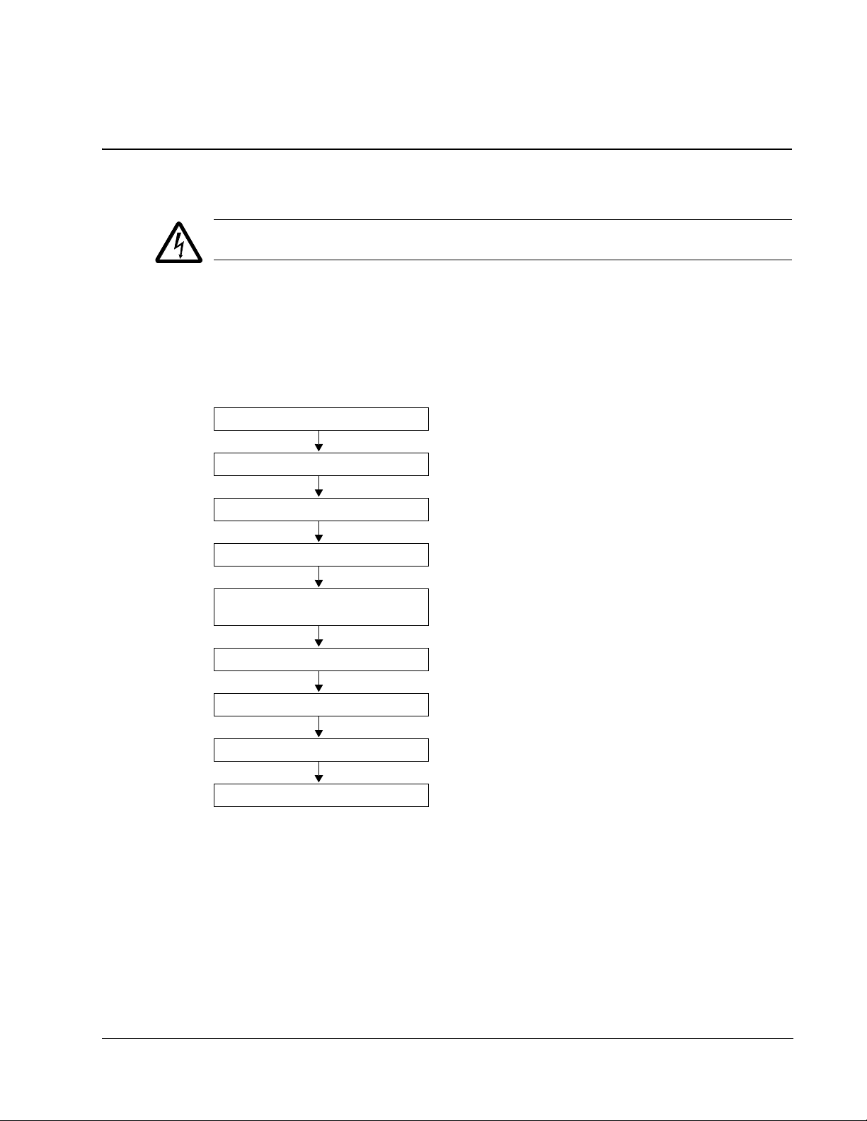
Installation flow chart
The installation of the ACH550 adjustable speed AC drive follows the outline below.
The steps must be carried out in the order shown. At the right of each step are
references to the detailed information needed for the correct installation of the unit.
Task Se e
PREPARE for installation Preparing for installation on page 1-10.
PREPARE the mounting location Prepare the mounting location on page 1-14.
REMOVE the front cover Remove front cover on page 1-16.
MOUNT the drive Mount the drive on page 1-17.
INSTALL wiring Wiring overview on page 1-18 and
CHECK installation Check installation on page 1-27.
REINSTALL the cover Re-install cover on page 1-27.
APPLY power Apply power on page 1-29.
START-UP Start-up on page 1-30.
Install the wiring on page 1-23.
Installation
Page 10
1-10 ACH550-UH User’s Manual
IP2040
PC00005
R70010
2
PC00003
30
o
Preparing for installation
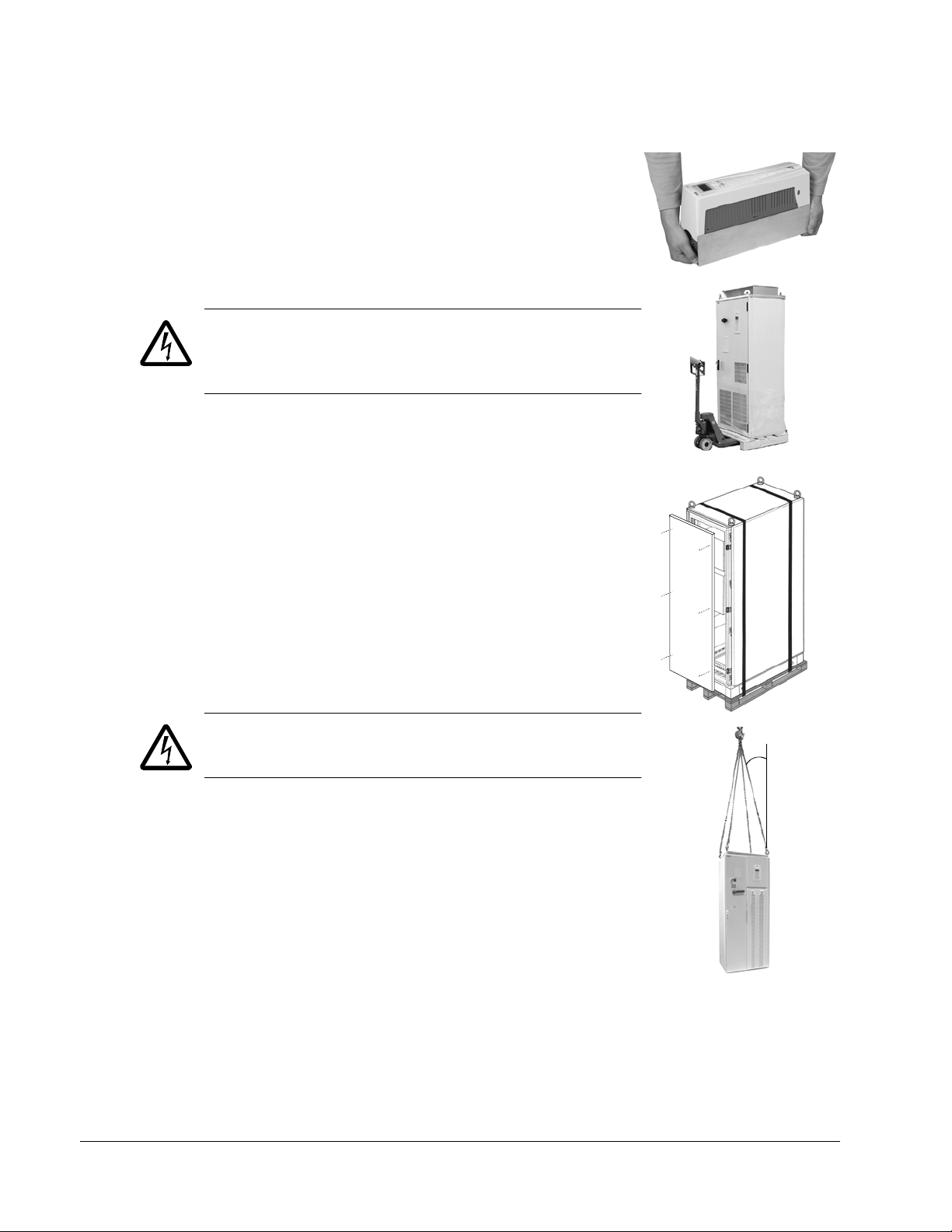
Lifting the drive
R1…R6
Lift the drive only by the metal chassis.
R7…R8
WARNING! Handle and ship floor mounted enclosures
only in the upright position. These units are not designed
to be laid on their backs.
1. Use a pallet truck to move the transport package/
enclosure to the installation site.
2. Remove the cabinet side panels for access to the
cabinet/pallet mounting bolts. (6 torx screws hold each
cabinet side panel in place. Leave the side panels off
until later.)
3. Remove the 4 bolts that secure the cabinet to the
shipping pallet.
WARNING! Use the lifting lugs/bars at the top of the unit
to lift R7/R8 drives.
4. Use a hoist to lift the drive. (Do not place drive in final
position until mounting site is prepared.)
Unpack the drive
1. Unpack the drive.
2. Check for any damage and notify the shipper
immediately if damaged components are found.
3. Check the contents against the order and the shipping
label to verify that all parts have been received.
Installation
Page 11
ACH550-UH User’s Manual 1-11
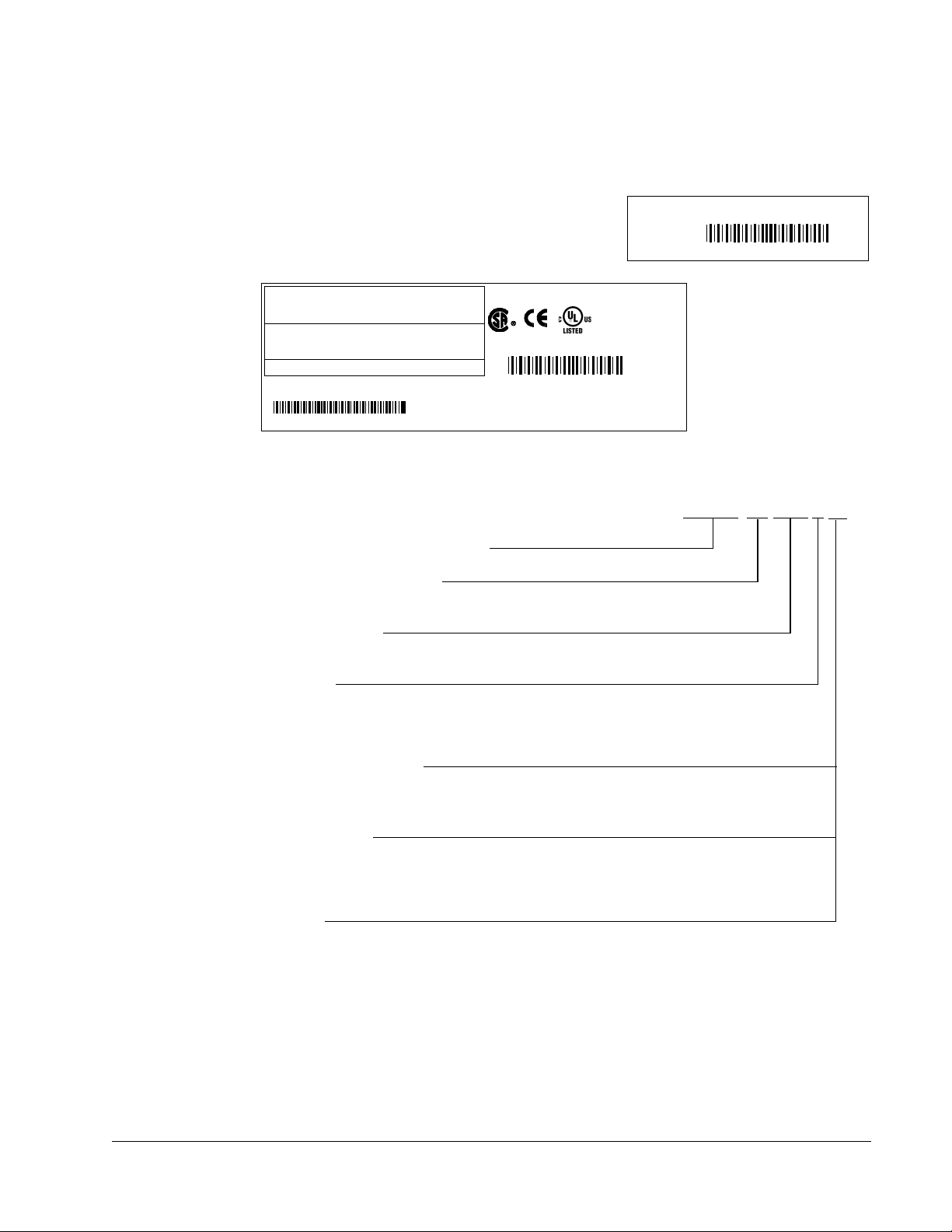
S/N
ACH550-UH-059A-2
2030700001
SW:
V.2. 06B
2030700001
Input
Voltage (U1)
Current (I1n)
3 PH 48…63 Hz
200…240 Vac
59.4 A
1 PH 4…63 Hz
200…240 Vac
59.4 A
Output
Voltage (U2)
Current (I2n)
3 PH 0…500 Hz
0…U1 Vac
59.4 A
3 PH 0…500 Hz
0…U1 Vac
28 A
ACH550-UH-059A-2
Power (Pn)
Mfg. Date: 01-December-2005
Org. Firmware: V.2.06B
ABB Inc.
Made in USA of foreign parts
10 HP20 HP
kAIC
S/N
2030700001
AC, HVAC Drive – 550 product series
Construction (region specific)
UH = Setup and parts specific to US installation and NEMA compliance
Output current rating
e.g. 08A8 = 8.8A See section Ratings for details on page 1-299
Volta g e r a ting
2 = 208…240 VAC
4 = 380…480 VAC
6 = 500…600 VAC
Enclosure protection class
No specification = UL type 1 / NEMA 1 / IP 21
+B055 = UL type 12 / NEMA 12 / IP 54
Fieldbus Adapter
+K451 = DeviceNet Adapter +K462 = ControlNet Adapter
+K452 = LonWorks Adapter +K466 = EtherNet Adapter
+K454 = Profibus Adapter
I/O Options
+L511 = Relay Output Extension
+L512 = 115/230 V Digital Input Interface
ACH550-UH-08A8-4+...
Drive identification
Drive labels
To determine the type of drive you are installing, refer to either:
• Serial number label attached on upper part of
the chokeplate between the mounting holes.
• Type code label attached on the heat sink – on
the side of the enclosure.
Type code
Use the following chart to interpret the type code found on either label.
Ratings and frame size
The chart in section Ratings on page 1-299 lists technical specifications, and
identifies the drive’s frame size. To read the Ratings table, you need the “Output
current rating” entry from the type code (see above). Also, when using the Ratings
tables, note that there are different tables for each drive “Voltage rating”.
Installation
Page 12

1-12 ACH550-UH User’s Manual
Motor compatibility
The motor, drive, and supply power must be compatible:
Motor
Specification
Motor type 3-phase induction motor –
Nominal current Motor value is within this
range: 0.15…1.5 * I
(I
2N
Nominal frequency 10…500 Hz –
Voltage range Motor is compatible with
Insulation 500…600 V drives: Either
the ACH550 voltage range.
the motor complies with
NEMA MG1 Part 31, or a
du/dt filter is used between
the motor and drive.
Verify Reference
• Type code label on drive, entry for Output I
= normal use current)
2N
or
• Type code on drive and rating table in
Technical data on page 1-299.
208…240 V (for ACH550-xx-xxxx-2) or
380…480 V (for ACH550-xx-xxxx-4)
500…600 V (for ACH550-xx-xxxx-6)
For ACH550-xx-xxxx-6
Tools required
To install the ACH550 you need the following:
• Screwdrivers (as appropriate for the mounting hardware used)
• Wire stripper
• Tape measure
2N
,
•Drill
• Frame sizes R5…R8 with UL type 12 enclosure: Punch for conduit mounting
holes
• Frame sizes R7/R8: pallet truck and hoist
• For installations involving frame size R6…R8: The appropriate crimping tool for
power cable lugs. See Power terminal considerations – R6 Frame size.
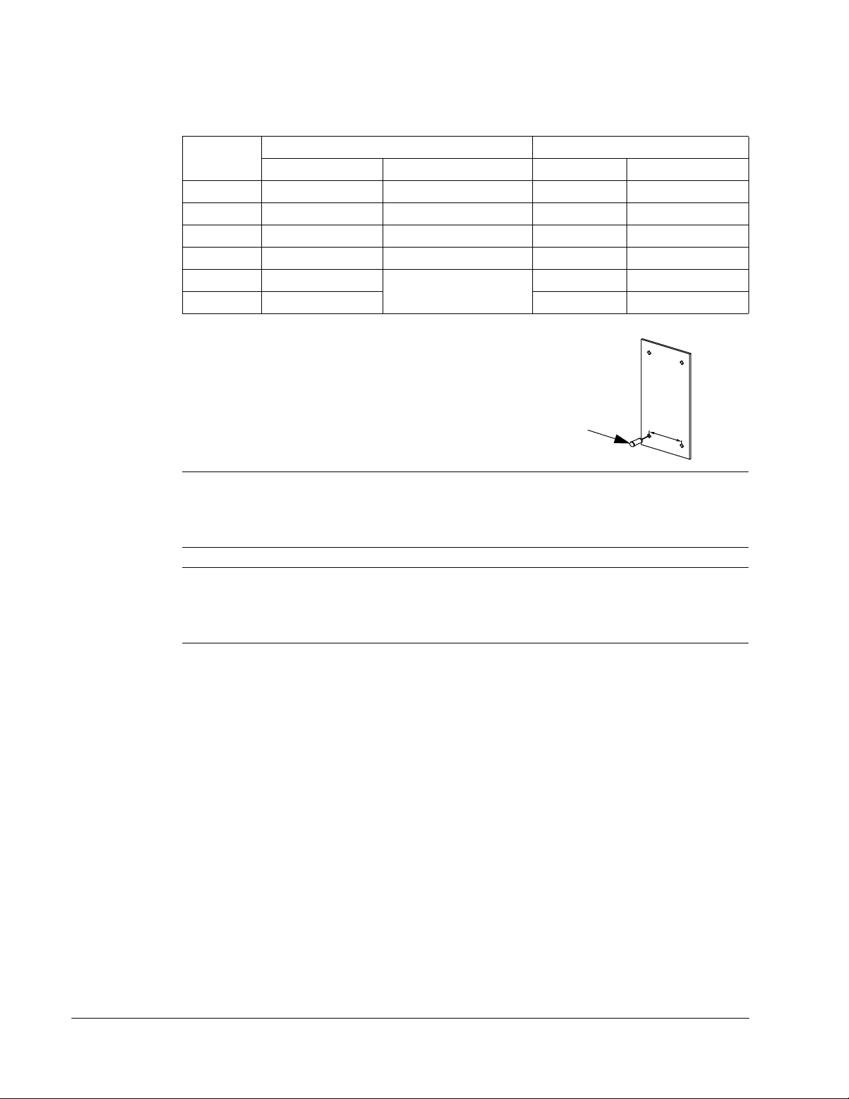
• Mounting hardware: screws or nuts and bolts, four each. The type of hardware
depends on the mounting surface and the frame size:
Frame Size Mounting Hardware Note
R1…R4 M5
R5 M6
R6 M8
R7…R8 M10
#10
1/4 in
5/16 in
7/16 Secures free standing cabinets if required.
• For installations involving frame size R7…R8: Hoist.
Installation
Page 13

ACH550-UH User’s Manual 1-13
Suitable environment and enclosure
Confirm that the site meets the environmental requirements. To prevent damage
prior to installation, store and transport the drive according to the environmental
requirements specified for storage and transportation. See Ambient conditions on
page 1-328.
Confirm that the enclosure is appropriate, based on the site contamination level:
• UL type 1 enclosure. The site must be free of airborne dust, corrosive gases or
liquids, and conductive contaminants such as condensation, carbon dust, and
metallic particles.
• UL type 12 enclosure. This enclosure provides protection from airborne dust and
light sprays or splashing water from all directions.
Suitable mounting location
Confirm that the mounting location meets the following constraints:
• R1…R6: The drive must be mounted vertically on a smooth, solid surface, and in
a suitable environment as defined above.
• The drive must be located in a suitable environment as defined above.
• The minimum space requirements for the drive are the outside dimensions (see
Outside dimensions – R1…R6 on page
on page 1-326), plus air flow space around the unit (see Cooling
• The distance between the motor and the drive is limited by the maximum motor
cable length. See either Motor connection specifications on page 1-311, or
EN 61800-3 compliant motor cables on page 1-314.
• The mounting site must support the drive’s weight. See Weight on page 1-324.
Installing the drive
WARNING! Before installing the ACH550, ensure the input power supply to the drive
is off.
WARNING! Metal shavings or debris in the enclosure can damage electrical
equipment and create a hazardous condition. Where parts, such as conduit plates
require cutting or drilling, first remove the part. If that is not practical, cover nearby
electrical components to protect them from all shavings or debris.
1-325 or Outside dimensions – R7…R8
on page 1-320).
Installation
Page 14
1-14 ACH550-UH User’s Manual
X0002
1
For flange mounting (mounting the drive in a cooling air duct), see the appropriate
Flange Mounting Instructions:
Frame size
R1 FMK-A-R1 100000982 FMK-B-R1 100000990
R2 FMK-A-R2 100000984 FMK-B-R2 100000992
R3 FMK-A-R3 100000986 FMK-B-R3 100000994
R4 FMK-A-R4 100000988 FMK-B-R4 100000996
R5 AC8-FLNGMT-R5 ACS800-PNTG01U-EN - R6 AC8-FLNGMT-R6 - -
IP21 / UL type 1 IP54 / UL type 12
Kit Code (English) Kit Code (English)
Prepare the mounting location
The ACH550 should only be mounted where all of the
requirements defined in Preparing for installation on
page 1-10 are met.
1. Mark the position of the mounting holes.
Note: Frame sizes R3 and R4 have four holes along the top. Use only two. If
possible, use the two outside holes (to allow room to remove the fan for
maintenance).
Note: ACH400 drives can be replaced using the original mounting holes. For R1 and
R2 frame sizes, the mounting holes are identical. For R3 and R4 frame sizes, the
inside mounting holes on the top of ACH550 drives match ACH400 mounts.
Installation
Page 15
ACH550-UH User’s Manual 1-15
PC00023
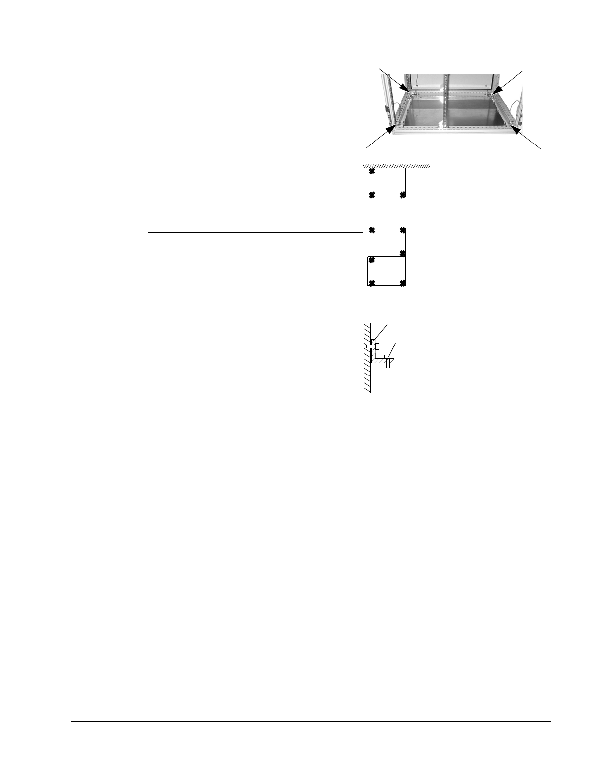
Fastening points when installed
back against a wall (Top view)
Fastening points when installed
back against back
Cabinet top
M12 bolt (1/2 to 9/16 in)
L-bracket
Fastening the cabinet at the top
using L-brackets (side view)
Note: Frame sizes R7 and R8 have
mounting holes inside the enclosure base.
See Mounting dimensions on page 1-323.
Where it is not possible to use either
mounting hole at the back of the base, use
an L-bracket at the top of the enclosure to
secure the cabinet to a wall or to the back of
another enclosure. Bolt the L-bracket to the
enclosure using the lifting lug bolt hole on
the top of the enclosure.
2. Drill holes of appropriate size in the
mounting location.
Installation
Page 16
1-16 ACH550-UH User’s Manual
3
IP2000
1
2
3
4
1
2
FM
1
R70020
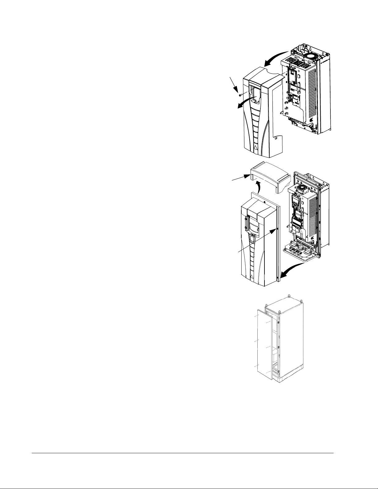
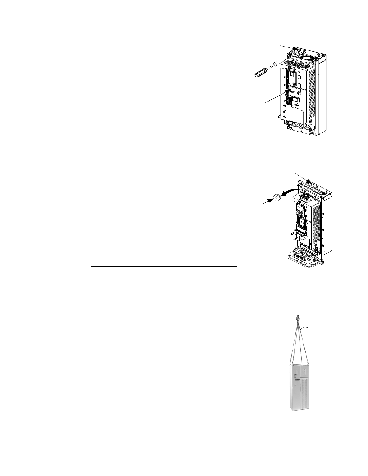
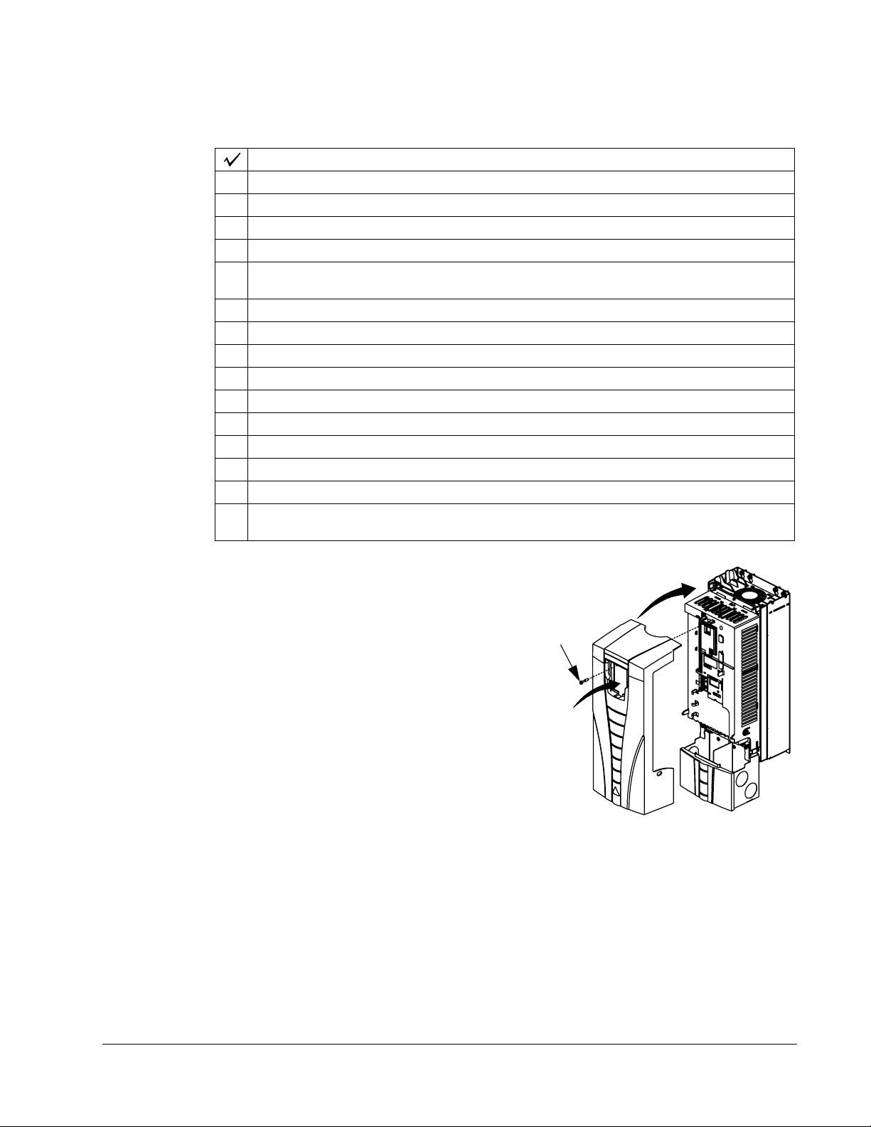
Remove front cover
R1…R6, UL type 1
1. Remove the control panel, if attached.
2. Loosen the captive screw at the top.
3. Pull near the top to remove the cover.
R1…R6, UL type 12
1. If hood is present: Remove screws (2) holding
the hood in place.
2. If hood is present: Slide hood up and off of the
cover.
3. Loosen the captive screws around the edge of
the cover.
4. Remove the cover.
R7…R8, Cabinet Door
1. To open the cabinet door, loosen the quarterturn screws that hold the cabinet door closed.
R7…R8, Side Panels
The side panels were removed to take the
cabinet off the pallet. Installation access is
easier if these panels are kept off throughout
the installation.
Installation
Page 17
ACH550-UH User’s Manual 1-17
IP2002
1
2
2
1, 3
FM
PC00003
30
o
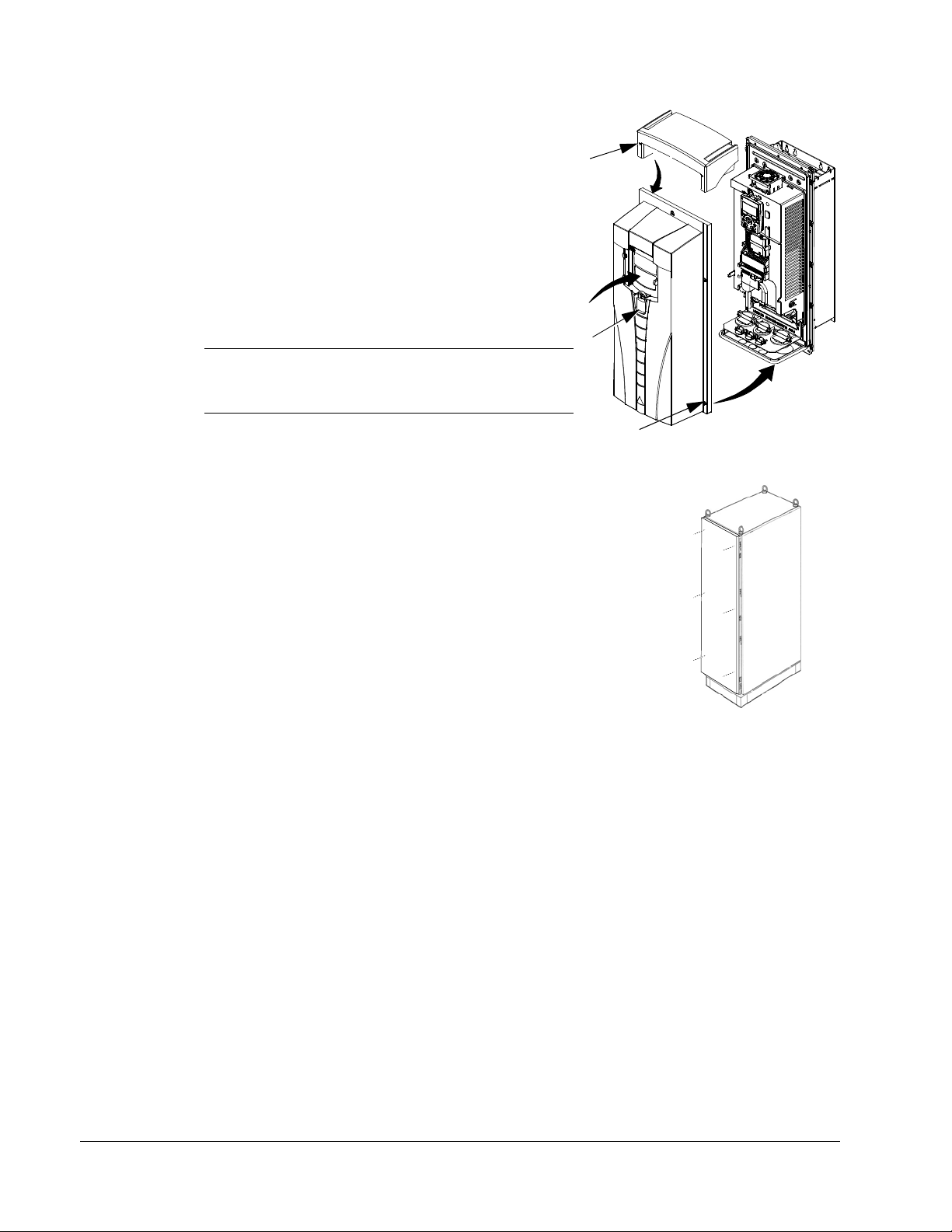
Mount the drive
R1…R6, UL type 1
1. Position the ACH550 onto the mounting screws
or bolts and securely tighten in all four corners.
Note: Lift the ACH550 by its metal chassis.
2. Non-English speaking locations: Add a warning
sticker in the appropriate language over the
existing warning on the top of the module.
R1…R6, UL type 12
For the UL type 12 enclosures, rubber plugs are required in the holes provided for
access to the drive mounting slots.
1. As required for access, remove the rubber plugs.
Push plugs out from the back of the drive.
2. R5 & R6: Align the sheet metal hood (not shown)
in front of the drive’s top mounting holes. (Attach
as part of next step.)
3. Position the ACH550 onto the mounting screws
or bolts and securely tighten in all four corners.
Note: Lift the ACH550 by its metal chassis
(frame size R6 by the lifting holes on both sides
at the top).
4. Re-install the rubber plugs.
5. Non-English speaking locations: Add a warning sticker in the appropriate language
over the existing warning on the top of the module.
R7…R8
1. Use a hoist to move the cabinet into position.
Note: If the cabinet location does not provide access to
the cabinet sides, be sure to re-mount side panels before
positioning cabinet.
2. Install and tighten mounting bolts.
Installation
Page 18
1-18 ACH550-UH User’s Manual
Wiring overview
Conduit kit
Wiring R1…R6 drives with the UL type 1 Enclosure requires a conduit kit with the
following items:
• conduit box
• screws
• cover
The kit is included with UL type 1 Enclosures.
Wiring requirements
WARNING! Ensure the motor is compatible for use with the ACH550. The ACH550
must be installed by a competent person in accordance with the considerations
defined in Preparing for installation on page 1-10. If in doubt, contact your local ABB
sales or service office.
As you install the wiring, observe the following:
• There are two sets of wiring instructions – one set for each enclosure type (UL
type 1 and UL type 12). Be sure to select the appropriate procedure.
• For the power connection points on the drive see the Connection diagrams
section below.
• Use separate, metal conduit runs to keep these three classes of wiring apart:
– Input power wiring.
– Motor wiring. (Use a separate, metal conduit run for each drive)
– Control/communications wiring.
• When installing input power and motor wiring, refer to the following, as
appropriate:
Terminal Description Specifications and Notes
U1, V1, W1* 3-phase power supply input Input power connections on page 1-303.
PE Protective Ground Ground connections on page 1-307.
U2, V2, W2 Power output to motor Motor connections on page 1-311.
* The ACH550 -xx-xxxx-2 (208…240V series) can be used with a single phase supply, if output
current is derated by 50%. For single phase supply voltage connect power at U1 and W1.
• To locate input power and motor connection terminals, see Connection diagrams
starting on page 1-20. For specifications on power terminals, see Drive’s power
connection terminals on page 1-309.
Installation
• For corner grounded TN systems, see section Unsymmetrically grounded
networks on page 1-307.
• For IT systems, see section Floating networks on page 1-308.
• For frame size R6, see Power terminal considerations – R6 Frame size on page
1-309 to install the appropriate cable lugs.
Page 19

ACH550-UH User’s Manual 1-19
• For details on control connections, refer to the following sections:
– Drive’s control connection terminals on page 1-318.
– Control connections on page 1-317.
– Application macros starting on page 1-49.
– Complete parameter descriptions on page 1-80.
– Embedded fieldbus on page 1-187.
– Fieldbus adapter on page 1-261.
• For electro-magnetic compliance (EMC), follow local codes and the requirements
in Motor cable requirements for CE & C-Tick compliance on page 1-313. For
example:
– Properly ground the wire screen cable shields.
– Keep individual un-screened wires between the cable clamps and the screw
terminals as short as possible.
– Route control cables away from power cables.
Installation
Page 20
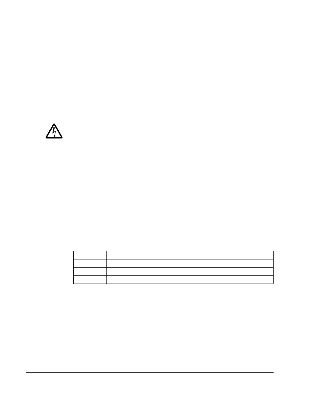
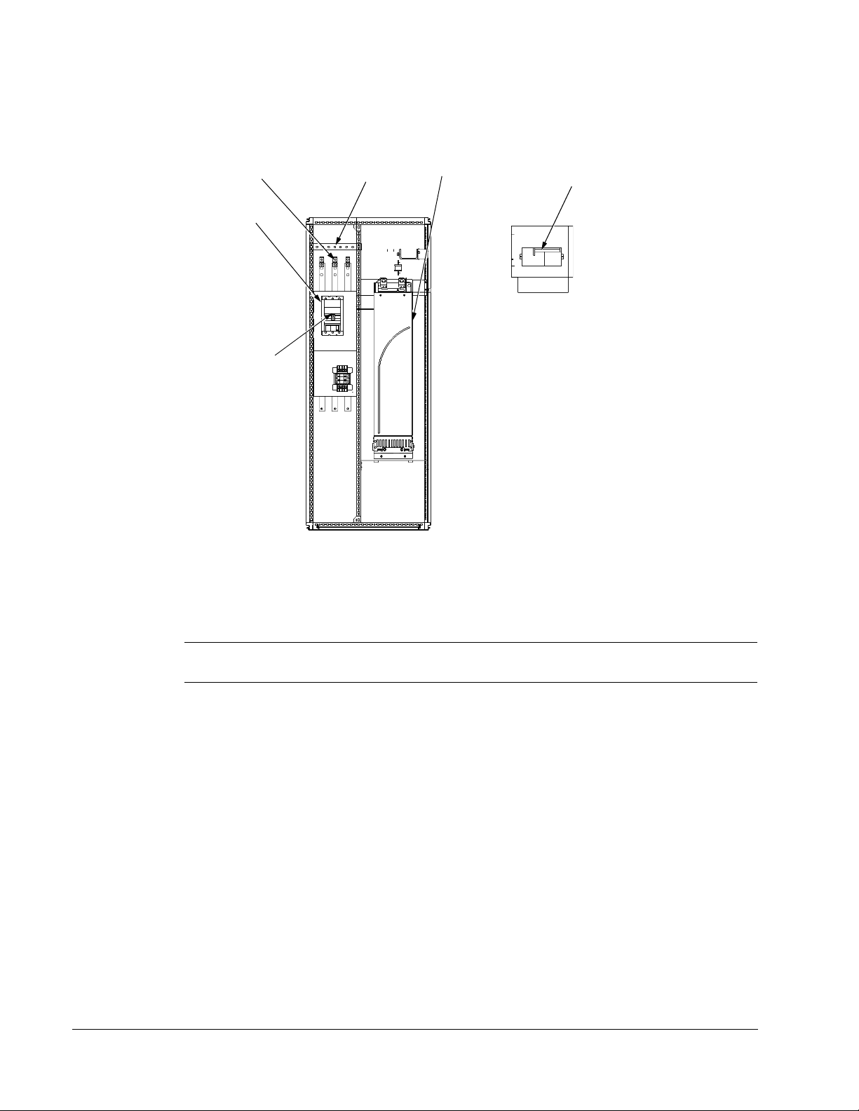
1-20 ACH550-UH User’s Manual
Panel Connector
Power LED (Green)
Fault LED (Red)
Optional Module 1
X1 – Communications
Optional Module 2
GND
Power Output to Motor
Power Input
EM1
X1 – Analog Inputs and Outputs
X1 – Digital Inputs
X1 – Relay Outputs
(and 10 V Ref. Voltage Output)
(and 24 V Aux. Voltage Output)
EM3
PE
(U1, V1, W1)
(U2, V2, W2)
X0003
(RS485)
R5/R6 differ.
See next page.
Frame Sizes
R1…R4 (Diagram shows the R3 frame.)
J2 – DIP Switches
J2
ON
off position on position
for RS485 Termination
J2
ON
Terminals Not Used
J1 – DIP Switches for Analog Inputs
AI1: (in Voltage Position)
AI2: (in Current Position)
ON
ON
The switch is one of two types:
Alternate
Original
Illustration of available switch
positions; not default settings
Illustration of available switch
positions; not default settings
Connection diagrams
The following diagrams show:
• The terminal layout for frame size R3, which, in general, applies to frame sizes
R1
• The R5/R6 power and ground terminals.
• The terminal layout for R7/R8.
…R6, except for the R5/R6 power and ground terminals.
Installation
WARNING! To avoid danger, or damage to the drive, on IT systems and corner
grounded TN systems, see section Disconnecting the internal EMC filter on
page 1-22.
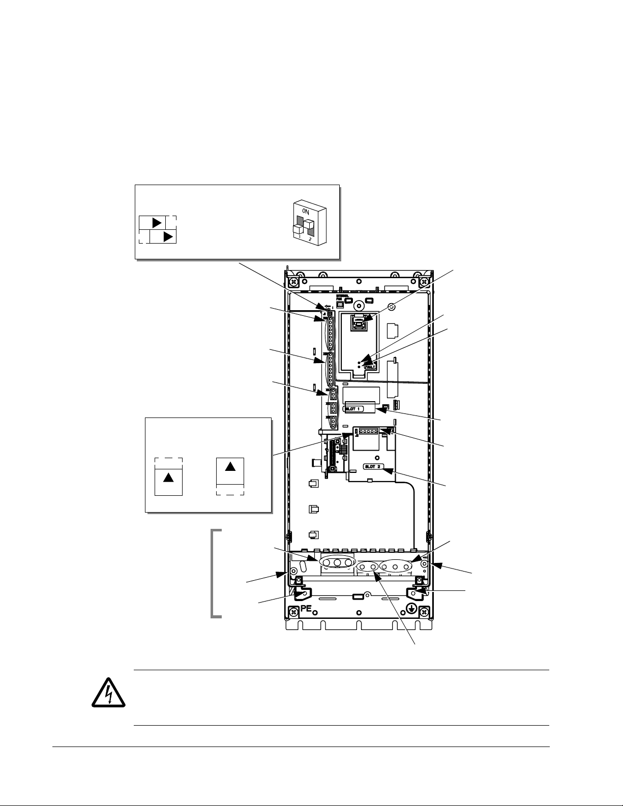
Page 21
ACH550-UH User’s Manual 1-21
GND
Power Input
PE
(U1, V1, W1)
X0011
F1
F2
Power Input
PE
(U1, V1, W1)
F1
F2
X0013
Power Output to Motor
(U2, V2, W2)
R5 R6
GND
GND
Power Output to Motor
(U2, V2, W2)
Terminals Not Used
Terminals Not Used
The following diagram shows the power and ground terminal layout for frame sizes
R5 and R6.
WARNING! To avoid danger, or damage to the drive, on IT systems and corner
grounded TN systems, see section Disconnecting the internal EMC filter on
page 1-22.
Installation
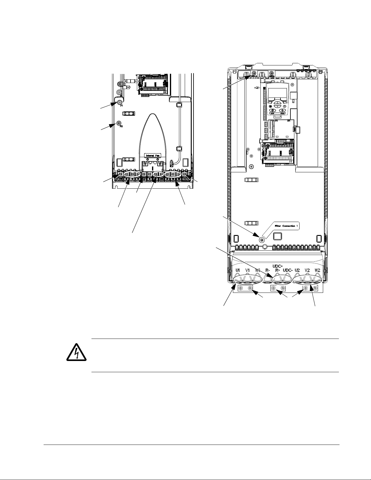
Page 22
1-22 ACH550-UH User’s Manual
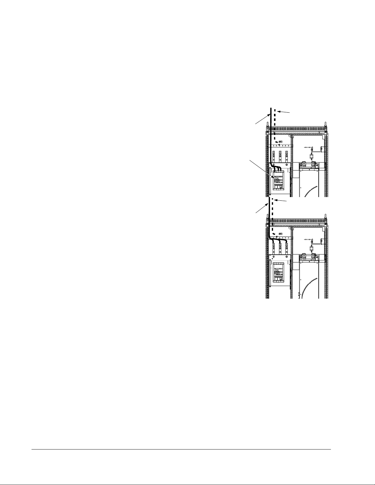
Ground Lug
Bar
ACH550
R7
Motor
Terminals
Input Power
Te rm in a ls
Control Wires
(X1)
Terminal Strip
Only on
ACH550-UH
The following diagram shows the power and ground terminal layout for frame size
R7 (R8 is similar).
Disconnecting the internal EMC filter
On certain types of systems, you must disconnect the internal EMC filter, otherwise
the system will be connected to ground potential through the EMC filter capacitors,
which might cause danger, or damage the drive.
Note: When the internal EMC filter is disconnected, the drive is not EMC compatible.
The following table shows the installation rules for the EMC filter screws in order to
connect or disconnect the filter, depending on the system type and the frame size.
For more information on the different system types, see Floating networks on page
1-308 and Unsymmetrically grounded networks on page 1-307.
Installation
Page 23
ACH550-UH User’s Manual 1-23
PE
M
ohm
The locations of screws EM1 and EM3 are shown in the diagram on page 1-20. The
locations of screws F1 and F2 are shown in the diagram on page 1-21.
Frame
sizes
R1…R3
R4
R5…R6
x = Install the screw. (EMC filter will be connected.)
= Replace the screw with the provided polyamide screw. (EMC filter will be disconnected.)
–
= Remove the screw. (EMC filter will be disconnected.)
Screw
EM1 x x
EM3 x
EM1 x x –
EM3 x ––
F1 x x –
F2 x x –
Symmetrically
grounded TN systems
(TN-S systems)
Corner grounded
TN systems
IT systems (ungrounded
or high-resistance-
grounded [> 30 ohm])
Install the wiring
Checking motor and motor cable insulation
WARNING! Check the motor and motor cable insulation before connecting the drive
to input power. For this test, make sure that motor cables are NOT connected to the
drive.
1. Complete motor cable connections to the motor, but NOT to the drive output
terminals (U2, V2, W2).
2. At the drive end of the motor cable, measure the insulation
resistance between each motor cable phase and Protective
Earth (PE): Apply a voltage of 1 kV DC and verify that
resistance is greater than 1 Mohm.
Installation
Page 24
1-24 ACH550-UH User’s Manual
2
X0007
3
X0005
4
IP2004
7
7
5
10
8
IP2005
12
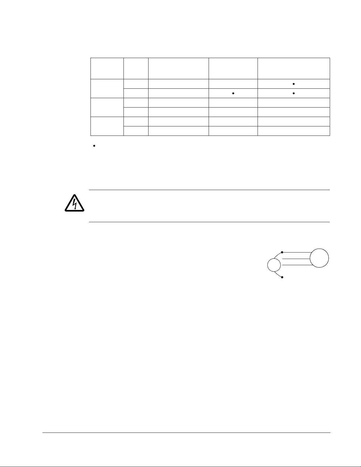
R1…R6, wiring UL type 1 enclosure
1. Open the appropriate knockouts in the
conduit box. (See Conduit kit on page 1-18.)
2. Install thin-wall conduit clamps (not supplied).
3. Install conduit box.
4. Connect conduit runs for input power, motor
and control cables to the box.
5. Route input power and motor wiring through
separate conduits.
6. Strip wires.
7. Connect power, motor, and ground wires to
the drive terminals. See Wiring requirements
on page 1-18 and table on the tightening
torques on page 1-309.
Note: For R5 frame size, the minimum power cable size is 25 mm2 (4 AWG). For R6
frame size, refer to Power terminal considerations – R6 Frame size on page 1-309.
8. Route the control cables through the conduit
(not the same conduit as either input power or
motor wiring).
9. Use available secure points and tie strap
landings to permanently secure control wiring
at a minimum distance of 6 mm (1/4") from
power wiring.
10. Strip the control cable sheathing and twist the
copper screen into a pig-tail.
11. Connect the ground screen pig-tail for digital
and analog I/O cables at X1-1. (Ground only
at drive end.)
12. Connect the ground screen pig-tail for RS485
cables at X1-28 or X1-32. (Ground only at
drive end.)
Installation
13. Strip and connect the individual control wires to the drive terminals. See Wiring
requirements on page 1-18.
14. Install the conduit box cover (1 screw).
Page 25
ACH550-UH User’s Manual 1-25
IP50131
R1…R4
IP5023
1
R5, R6
2
IP5006
3
IP5007
6
4
7
IP5008
9…11
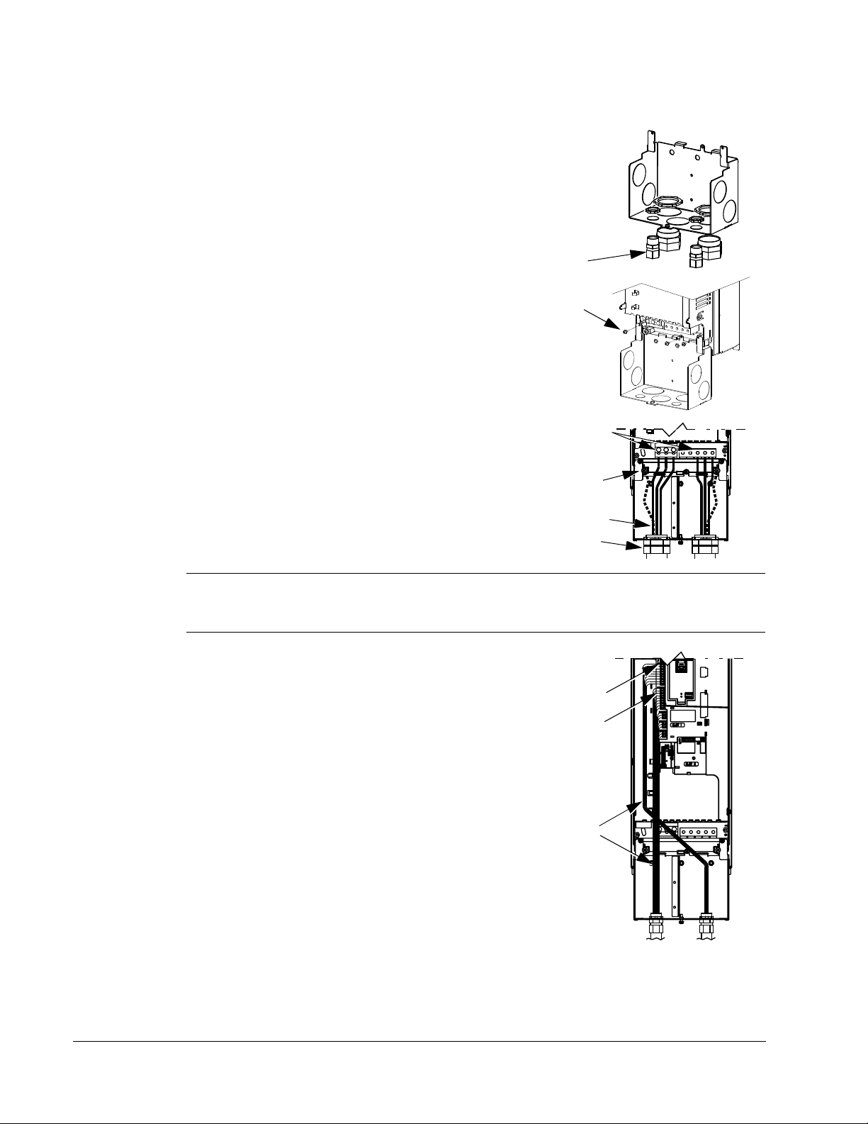
R1…R6, wiring UL type 12 enclosure
1. Step depends on Frame Size:
• Frame Sizes R1…R4: Remove and discard the
cable seals where conduit will be installed. (The
cable seals are cone-shaped, rubber seals on
the bottom of the drive.)
• Frame Sizes R4 and R5: Use punch to create
holes for conduit connections as needed.
2. For each conduit run (input power, motor and
control wiring must be separate), install water tight
conduit connectors (not supplied).
3. Route the power wiring through conduit.
4. Route the motor wiring through conduit (not the
same conduit as input power wiring run).
5. Strip the wires.
6. Connect the power, motor, and ground wires to
the drive terminals. See Wiring requirements on
page 1-18, Connection diagrams on page 1-20 and
table for tightening torques on page 1-309.
Note: For R5 frame size, the minimum power cable size is 25 mm2 (4 AWG). For R6
frame size, refer to Power terminal considerations – R6 Frame size on page 1-309.
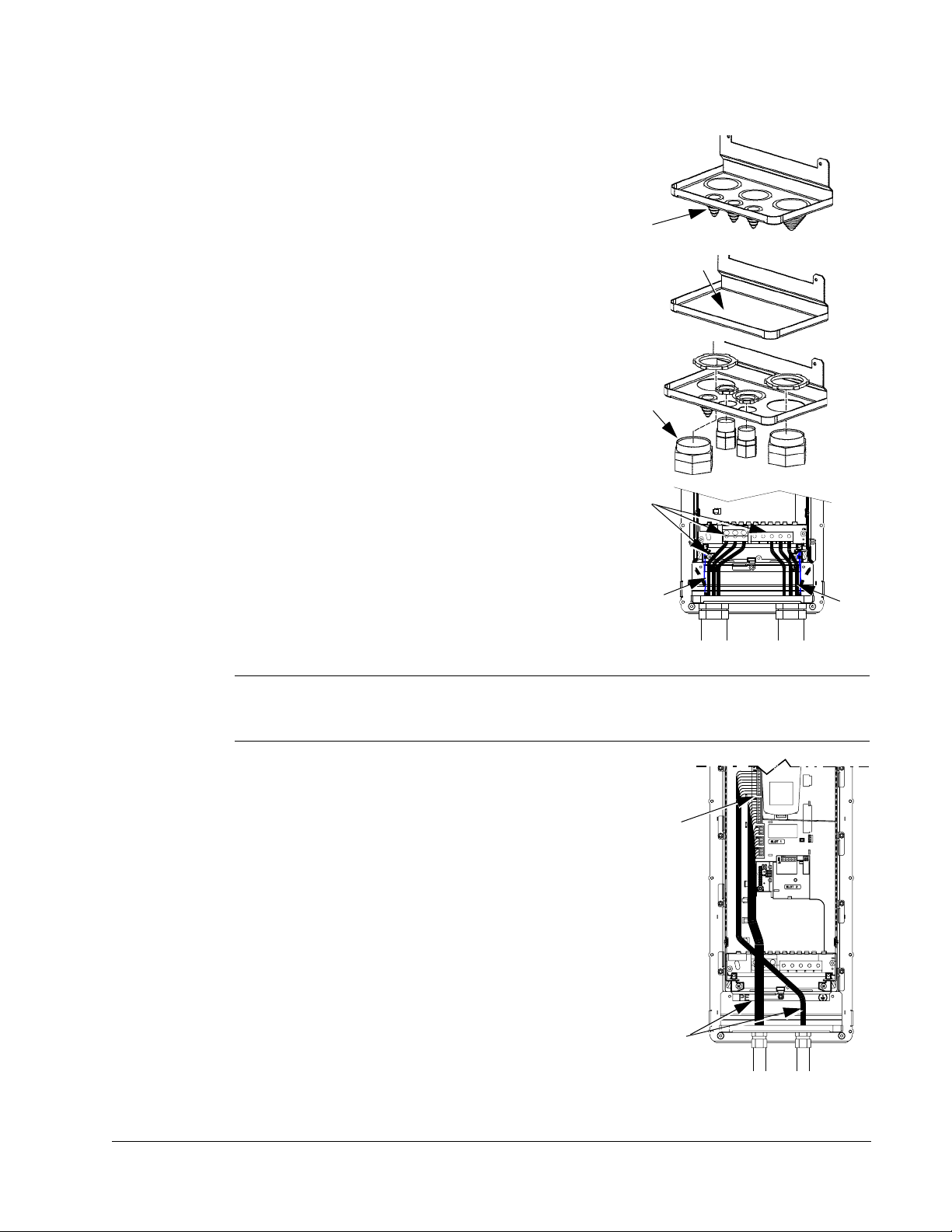
7. Route the control cables through the conduit (not
the same conduit as either input power or motor
wiring runs).
8. Use available secure points and tie strap landings to
permanently secure control wiring at a minimum
distance of 6 mm (1/4") from power wiring.
9. Strip the control cable sheathing and twist the
copper screen into a pig-tail.
10. Connect the ground screen pig-tail for digital and
analog I/O cables at X1-1. (Ground only at drive
end.)
11. Connect the ground screen pig-tail for RS485 cables
at X1-28 or X1-32. (Ground only at drive end.)
12. Strip and connect the individual control wires to the drive
terminals. See Wiring requirements on page 1-18.
13. Install the conduit box cover (1 screw).
Installation
Page 26
1-26 ACH550-UH User’s Manual
BP0054
Input Power
Gnd
Cable
Term in al St r ip
Only on
ACH550-UH
BP0054
Motor
Gnd
Cable
R7…R8, wiring (both enclosure types)
The figures show connections in the R7 cabinet, the R8 cabinet is similar.
1. Remove the conduit connection plate from the top of the left bay.
2. Route the input power, motor and control cables to the top of the cabinet. Each cable
type (input power, motor, and control) must be in separate conduit.
3. Use punch to create holes for conduit connections as needed.
4. UL type 12 Enclosure: For each conduit
run (input power, motor and control wiring
must be separate), install water tight
conduit connectors (not supplied).
5. Connect input power and motor cables to
the bus terminals. See Wiring requirements
on page 1-18, Connection diagrams on
page 1-20.
6. Connect grounds to ground bar.
7. Use available secure points and tie strap
landings to permanently secure control
wiring at a minimum distance of 6 mm
(1/4") from power wiring.
8. Strip the control cable sheathing and twist
the copper screen into a pig-tail.
9. Connect the ground screen pig-tail for
digital and analog I/O cables at X1-1.
(Ground only at drive end.)
10. Connect the ground screen pig-tail for
RS485 cables at X1-28 or X1-32. (Ground
only at drive end.)
11. Strip and connect the individual control wires to the drive terminals. See Wiring
requirements on page 1-18.
Installation
Page 27
ACH550-UH User’s Manual 1-27
3
1
2
IP2009
Check installation
Before applying power, perform the following checks.
Check
Installation environment conforms to the drive’s specifications for ambient conditions.
The drive is mounted securely.
Space around the drive meets the drive’s specifications for cooling.
The motor and driven equipment are ready for start.
For floating networks (R1…R6): The internal RFI filter is disconnected (screws EM1 & EM3 or
F1 & F2).
The drive is properly grounded.
The input power voltage matches the drive nominal input voltage range.
The input power connections at U1, V1, and W1 are connected and tightened as specified.
The input power branch circuit protection is installed.
The motor connections at U2, V2, and W2 are connected and tightened as specified.
The input power, motor and control wiring are routed through separate conduit runs.
NO power factor compensation capacitors are in the motor cable.
The control connections are connected and tightened as specified.
NO tools or foreign objects (such as drill shavings) are inside the drive.
NO alternate power source for the motor (such as a bypass connection) is connected – no
voltage is applied to the output of the drive.
Re-install cover
R1…R6, UL type 1
1. Align the cover and slide it on.
2. Tighten the captive screw.
3. Re-install the control panel.
Installation
Page 28
1-28 ACH550-UH User’s Manual
2
1
4
3
5
6
FM
1
R70020
R1…R6, UL type 12
1. Align the cover and slide it on.
2. Tighten the captive screws around the edge of
the cover.
3. R1…R4: Slide the hood down over the top of
the cover.
4. R1…R4: Install the two screws that attach the
hood.
5. Re-install the control panel.
Note: The control panel window must be closed
to comply with UL type 12.
6. Optional: Add a lock (not supplied) to secure
the control panel window.
R7…R8, Covers
1. If side panels were removed and not remounted,
mount them now. Each panel requires 6 torx
screws.
2. Re-mount all high voltage shields.
3. Close all internal swing-out panels and secure in
place with the quarter-turn screws.
4. Close the cabinet door and secure in place with
the quarter-turn screws.
Installation
Page 29
ACH550-UH User’s Manual 1-29
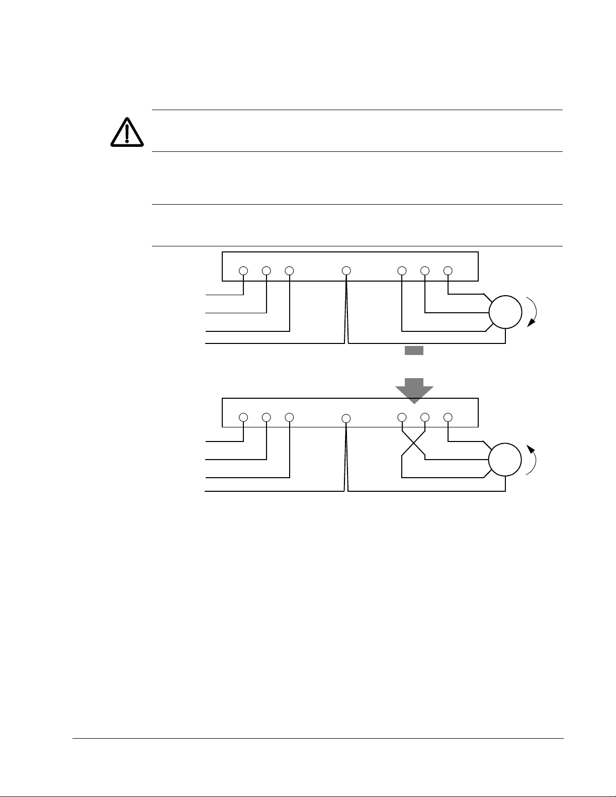
U1 V1 W1 U2 V2 W2
L1
L2
L3
Motor
Drive
Input
FM
U1 V1 W1 U2 V2 W2
L1
L2
L3
Motor
Drive
Input
To change rotation direction,
switch motor leads
GND
GND
GND
GND
Apply power
Always re-install the covers before turning power on.
WARNING! The ACH550 will start up automatically at power up, if the external run
command is on.
1. Apply input power.
When power is applied to the ACH550, the green LED comes on.
Note: Before increasing motor speed, check that the motor is running in the desired
direction. To change rotation direction, switch motor leads as shown below.
Installation
Page 30

1-30 ACH550-UH User’s Manual
Start-up
The ACH550 has default parameter settings that are sufficient for many situations.
However, review the following situations. Perform the associated procedures as
appropriate.
Spin motor
When first installed and started the control panel displays a welcome screen with the
following options.
• Press Exit to commission the drive as described in section Start-up by changing
the parameters individually on page 1-47.
• Press Enter to move to the following options:
– Select “Commission Drive” to commission the drive as described in section
Start-Up by Start-up by using the Start-Up Assistant on page 1-47.
– Select “Spin Motor” to operate the motor prior to commissioning. This option
operates the motor without any commissioning, except entry of the motor data
as described below. Spin Motor is useful, for example, to operate ventilation
fans prior to commissioning.
Note: When using Spin Motor, the motor speed is limited to the range 1/3…2/3 of
maximum speed. Also, no interlocks are activated. Finally, once the drive is
commissioned, the welcome screen and this option no longer appear.
Motor data
The motor data on the ratings plate may differ from the defaults in the ACH550. The
drive provides more precise control and better thermal protection if you enter the
rating plate data.
1. Gather the following from the motor ratings plate:
• Voltage
• Nominal motor current
• Nominal frequency
• Nominal speed
• Nominal power
2. Edit parameters 9905…9909 to the correct values.
• Assistant Control Panel: The Start-Up Assistant walks you through this data entry
(see page 1-37).
• Basic Control Panel: Refer to Parameters Mode on page 1-35, for parameter
editing instructions.
Installation
Page 31

ACH550-UH User’s Manual 1-31
Macros
Note: Selecting the appropriate macro should be part of the original system design,
since the control wiring installed depends on the macro used.
1. Review the macro descriptions in Application macros on page 1-49. Use the macro
that best fits system needs.
2. Edit parameter 9902 to select the appropriate macro. Use either of the following:
• Use the Start-up Assistant, which displays the macro selection immediately after
motor parameter setup.
• Refer to Parameters Mode on page 1-35, for parameter editing instructions.
Tuning – parameters
The system can benefit from one or more of the ACH550 special features, and/or
fine tuning.
1. Review the parameter descriptions in Complete parameter descriptions starting on
page 1-80. Enable options and fine tune parameter values as appropriate for the
system.
2. Edit parameters as appropriate.
Fault and alarm adjustments
The ACH550 can detect a wide variety of potential system problems. For example,
initial system operation may generate faults or alarms that indicate set-up problems.
1. Faults and alarms are reported on the control panel with a number. Note the number
reported.
2. Review the description provided for the reported fault/alarm:
• Use the fault and alarm listings on pages 1-282 and 1-288 respectively, or
• Press the help key (Assistant Control Panel only) while fault or alarm is displayed.
3. Adjust the system or parameters as appropriate.
Installation
Page 32

1-32 ACH550-UH User’s Manual
Installation
Page 33
ACH550-UH User’s Manual 1-33
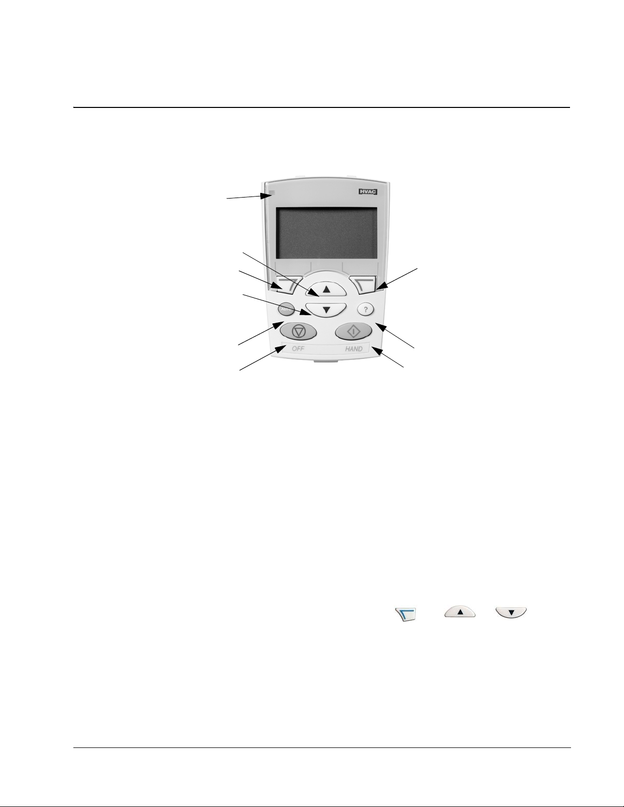
Status LED
UP
SOFT
KEY 1
DOWN
OFF
SOFT
KEY 2
HELP (always available)
HAND
AUTO
(Green when normal,
if flashing or red,
see Diagnostics.)
X0201
Control panel
HVAC control panel features
The ACH550 HVAC control panel (ACS-CP-B) features:
• Language selection for the display
• Drive connection that can be made or detached at any time
• Start-up assistant to facilitate drive commissioning
• Copy function for moving parameters to other ACH550 drives
• Backup function for saving parameter sets
• Context sensitive help
• Real-time clock
General display features
Soft key functions
The soft key functions are defined by text displayed just above each key.
Display contrast
To adjust display contrast, simultaneously press and or , as
appropriate.
Control panel
Page 34
1-34 ACH550-UH User’s Manual
HVAC control panel modes
The HVAC control panel has several different modes for configuring, operating and
diagnosing the drive. The modes are:
• Standard Display Mode – Shows drive status information and operates the drive.
• Parameters Mode – Edits parameter values individually.
• Start-up Assistant Mode – Guides the start-up and configuration.
• Changed Parameters Mode – Shows changed parameters.
• Fault Logger Mode – Shows the drive fault history.
• Drive Parameter Backup Mode – Stores or uploads the parameters.
• Clock Set Mode – Sets the time and date for the drive.
• I/O Settings Mode – Checks and edits the I/O settings.
• Alarm Mode – Reporting mode triggered by drive alarms.
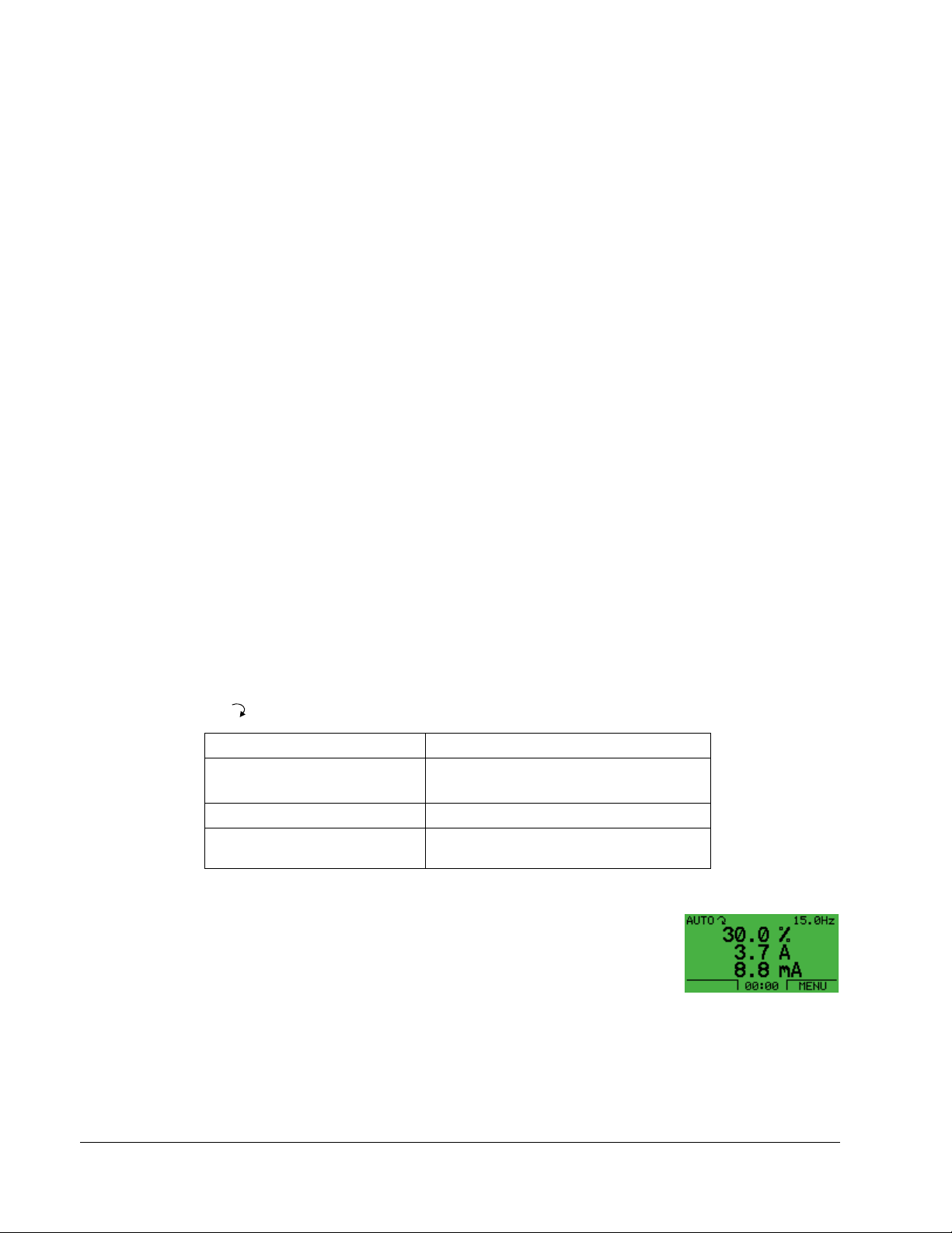
Standard Display Mode
Use the Standard Display Mode to read information on the drive’s status and to
operate the drive. To reach the Standard Display Mode, press EXIT until the LCD
display shows status information as described below.
Status information
Top. The top line of the LCD display shows the basic status information of the drive.
• HAND – Indicates that the drive control is local, that is, from the control panel.
•AUTO – Indicates that the drive control is remote, such as the basic I/O (X1) or
fieldbus.
• – Indicates the drive and motor rotation status as follows:
Control panel display Significance
Rotating arrow (clockwise or
counterclockwise)
Rotating dotted arrow blinking Drive is running but not at setpoint
Stationary dotted arrow Start command is present, but motor is not
• Drive is running and at setpoint
• Shaft direction is forward or reverse
running. E.g. start enable is missing.
• Upper right – shows the active reference.
Middle. Using parameter group 34, the middle of the LCD
display can be configured to display:
• One to three parameter values – The default display shows
parameters 0103 (OUTPUT FREQ) in percentages, 0104
(CURRENT) in amperes and 0120 (AI1) in milliamperes.
Control panel
– Use parameters 3401, 3408, and 3415 to select the parameters (from Group
01) to display. Entering “parameter” 0100 results in no parameter displayed.
For example, if 3401 = 0100 and 3415 = 0100, then only the parameter
specified by 3408 appears in the Control Panel display.
Page 35

ACH550-UH User’s Manual 1-35
– You can also scale each parameter in the display, for example, to convert the
motor speed to a display of conveyor speed. Parameters 3402…3405 scale
the parameter specified by 3401, parameters 3409…3412 scale the parameter
specified by 3408, etc.
• A bar meter rather than one of the parameter values.
– Enable bar graph displays using parameters 3404, 3411
and 3418.
Bottom. The bottom of the LCD display shows:
• Lower corners – show the functions currently assigned to the two soft keys.
• Lower middle – displays the current time (if configured to show the time).
Operating the drive
AUTO/HAND – The very first time the drive is powered up, it is in the auto control
(AUTO) mode, and is controlled from the Control terminal block X1.
To switch to hand control (HAND) and control the drive using the control panel, press
and hold the or button.
• Pressing the HAND button switches the drive to hand control while keeping the
drive running.
• Pressing the OFF button switches to hand control and stops the drive.
To switch back to auto control (AUTO), press and hold the button.
Hand/Auto/Off – To start the drive press the HAND or AUTO buttons, to stop the
drive press the OFF button.
Reference – To modify the reference (only possible if the display in the upper right
corner is in reverse video) press the UP or DOWN buttons (the reference changes
immediately).
The reference can be modified in the local control mode (HAND/OFF), and can be
parameterized (using Group 11 reference select) to also allow modification in the
remote control mode.
Note: The Start/Stop, Shaft direction and Reference functions are only valid in local
control (HAND/OFF) mode.
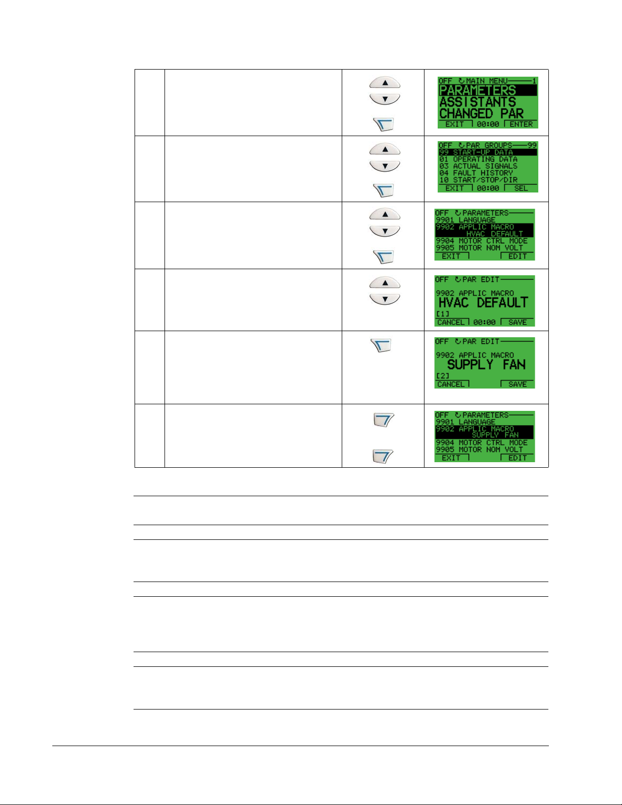
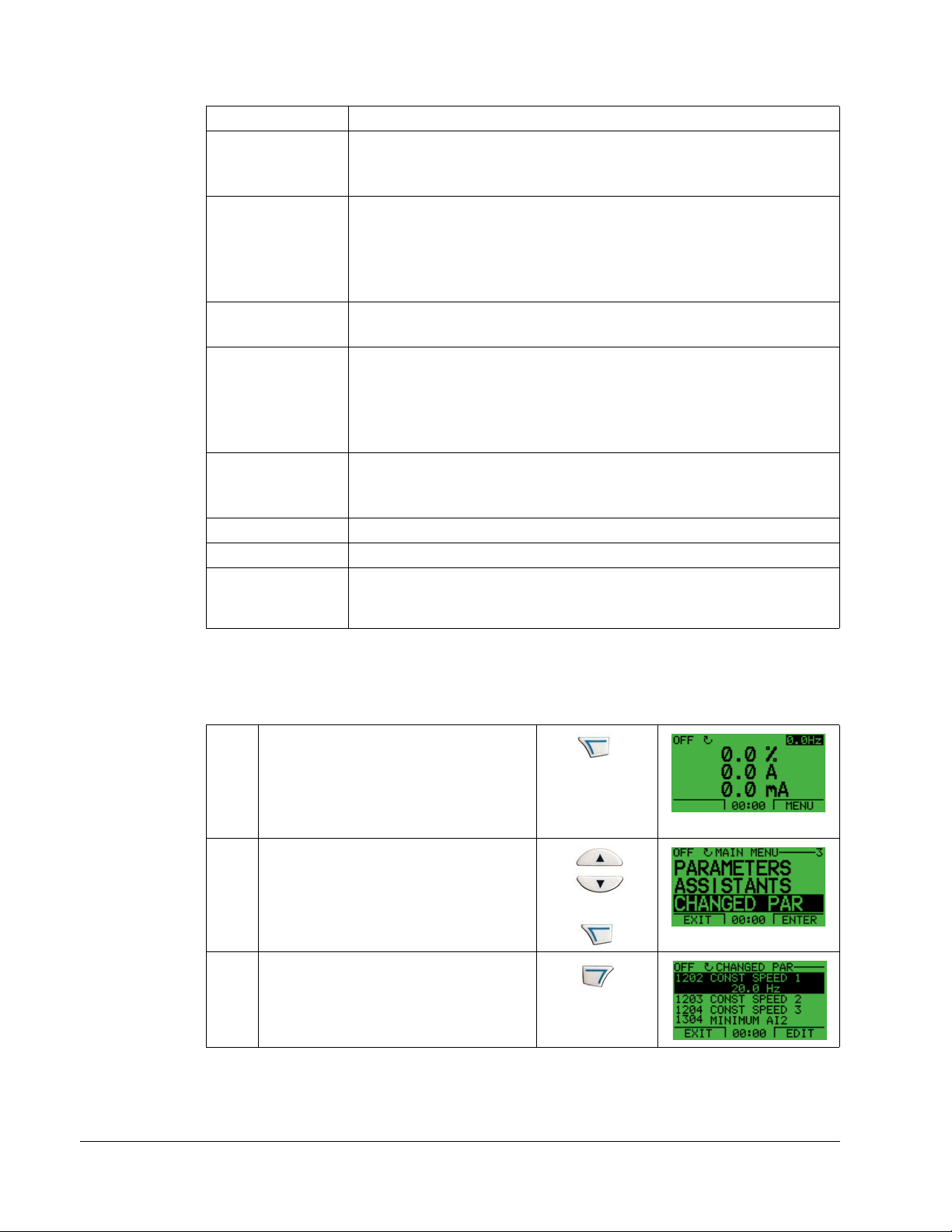
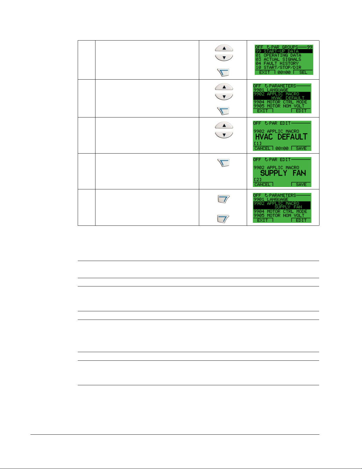
Parameters Mode
To change the parameters, follow these steps:
Select MENU to enter the main menu.
1
Control panel
Page 36
1-36 ACH550-UH User’s Manual
Select the Parameters mode with the UP/
DOWN buttons, and select ENTER to
select the Parameters Mode.
2
Select the appropriate parameter group
with the UP/DOWN buttons and select
SEL.
3
Select the appropriate parameter in a
group with the UP/DOWN buttons. Select
EDIT to change the parameter.
4
Press the UP/DOWN buttons to change
the parameter value.
5
Select SAVE to store the modified value
or select CANCEL to leave the set mode.
• Any modifications not saved are
6
7
cancelled.
• Each individual parameter setting is
valid immediately after pressing SAVE.
Select EXIT to return to the listing of
parameter groups, and again to return to
the main menu.
For detailed hardware description, see the Appendix.
Note: The current parameter value appears below the highlighted parameter.
Note: To view the default parameter value, press the UP/DOWN buttons
simultaneously.
Note: The most typical and necessary parameters to change are parameter groups
99 Start-up data, 10 Start/Stop/Dir, 11 Reference Select, 20 Limits, 21 Start/Stop, 22
Accel/Decel, 26 Motor Control and 30 Fault Functions.
Control panel
Note: To restore the default factory settings, select the application macro HVAC
Default.
Page 37
ACH550-UH User’s Manual 1-37
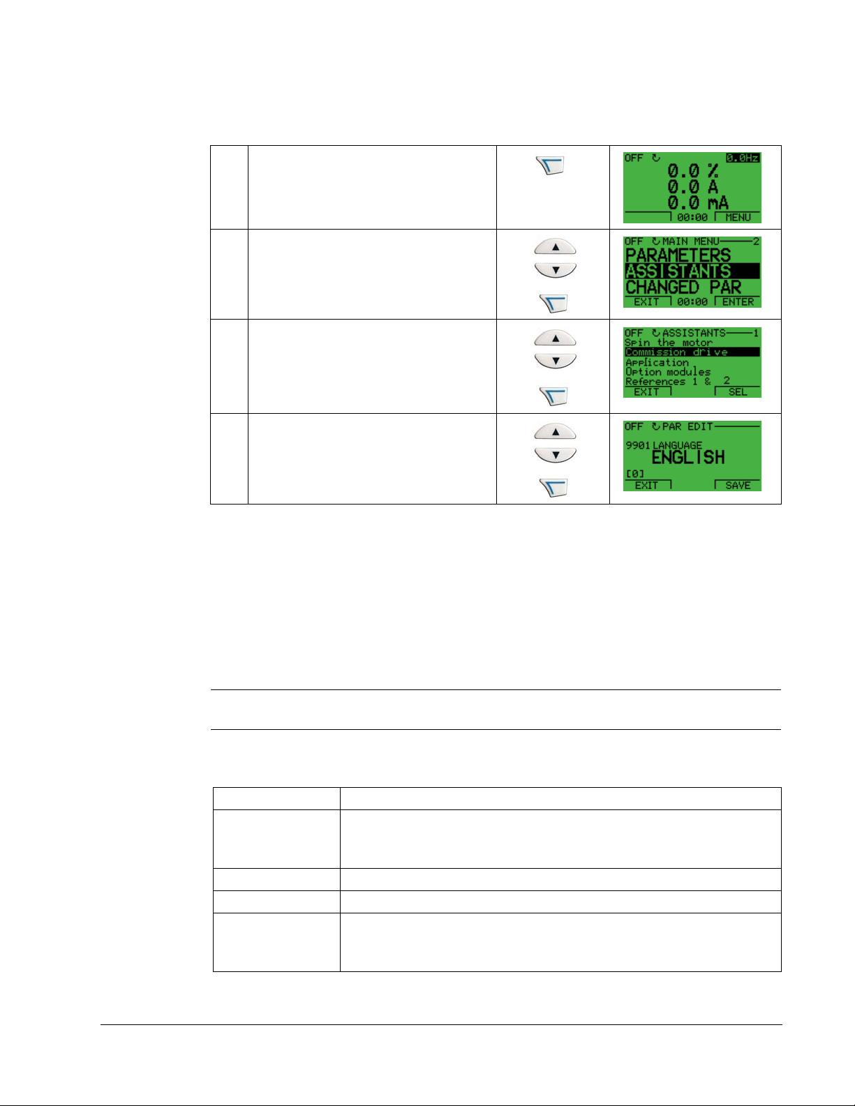
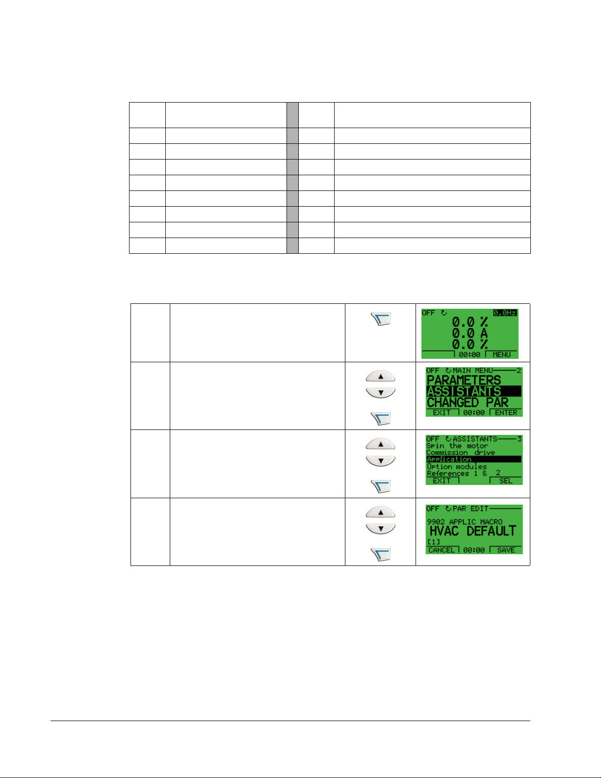
Start-Up Assistant Mode
To start the Start-Up Assistant, follow these steps:
Select MENU to enter the main menu
1
Select ASSISTANTS with the UP/DOWN
buttons and select ENTER.
2
Scroll to COMMISSION DRIVE with the
UP/DOWN buttons and select SEL.
3
Change the values suggested by the
assistant to your preferences and then
press SAVE after every change.
4
The Start-Up Assistant will guide you through the start-up.
The Start-Up Assistant guides you through the basic programming of a new drive.
(You should familiarize yourself with basic control panel operation and follow the
steps outlined above.) At the first start, the drive automatically suggests entering the
first task, Language Select.The assistant also checks the values entered to prevent
entries that are out of range.
The Start-Up Assistant is divided into tasks. You may activate the tasks one after the
other, as the Start-Up Assistant suggests, or independently.
Note: If you want to set the parameters independently, use the Parameters Mode.
The order of tasks presented by the Start-up Assistant depends on your entries. The
following task list is typical.
Task name Description
Spin the motor • Prompts for control panel display language selection.
• Prompts for motor data.
• Guides user through rotation check.
Commission drive Prompts for motor data.
Application Prompts for application macro selection.
References 1 & 2 • Prompts for the source of speed references 1 and 2.
• Prompts for reference limits.
• Prompts for frequency (or speed) limits.
Control panel
Page 38
1-38 ACH550-UH User’s Manual
Task name Description
Start/Stop Control • Prompts for the source for start and stop commands.
• Prompts for start and stop mode definition.
• Prompts for acceleration and deceleration times.
Protections • Prompts for current and torque limits.
• Prompts for the use of Run enable and Start enable signals.
• Prompts for the use of emergency stop.
• Prompts for Fault function selection.
• Prompts for Auto reset functions selection.
Constant Speeds • Prompts for the use of constant speeds.
• Prompts for constant speed values.
PID Control • Prompts for PID settings.
• Prompts for the source of process reference.
• Prompts for reference limits.
• Prompts for source, limits and units for the process actual value.
• Defines the use of Sleep function.
Low Noise Setup • Prompts for switching frequency.
• Prompts for definition of Flux optimization.
• Prompts for the use of Critical speeds.
Panel Display Prompts for display variable and unit settings.
Timed Functions Prompts for the use of Timed functions.
Output • Prompts for the signals indicated through the relay outputs.
• Prompts for signals indicated through the analog outputs AO1 and AO2.
Sets the minimum, maximum, scaling and inversion values.
Changed Parameters Mode
To view (and edit) a listing of all parameters that have been changed from macro
default values, follow these steps:
Select MENU to enter the menu.
1
Select CHANGED PAR with the UP/
DOWN buttons and select ENTER.
2
A list of changed parameters is displayed.
Select EXIT to exit the Changed
Parameters Mode.
3
Control panel
Page 39
ACH550-UH User’s Manual 1-39
Fault Logger Mode
Use the Fault Logger Mode to see drive fault history, fault state details and help for
the faults.
1. Select FAULT LOGGER in the Main Menu.
2. Press ENTER to see the latest faults (up to 10 faults, maximum).
3. Press DETAIL to see details for the selected fault.
• Details are available for the three latest faults.
4. Press DIAG to see the help description for the fault. See Diagnostics section.
Note: If a power off occurs, only the three latest faults will remain (with details only in
the first fault).
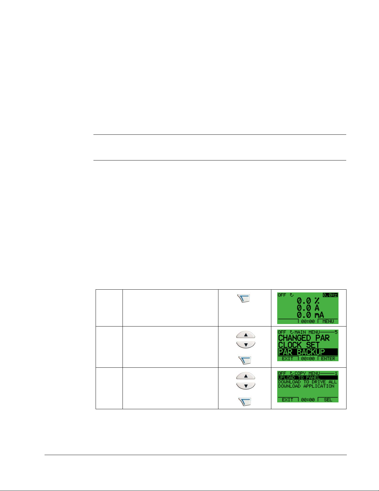
Drive Parameter Backup Mode
Use the Drive Parameter Backup Mode to export parameters from one drive to
another. The parameters are uploaded from a drive to the control panel and
downloaded from the control panel to another drive. Two options are available:
Par Backup Mode
The Assistant Control Panel can store a full set of drive parameters.
The Par Backup Mode has these functions:
• Upload to Panel – Copies all parameters from the drive to the Control Panel.
This includes user sets of parameters (if defined) and internal parameters such as
those created by the Motor Id Run. The Control Panel memory is non-volatile and
does not depend on the panel’s battery. To upload parameters to control panel,
follow these steps:
Select MENU to enter the main
menu.
1
Select PAR BACKUP with the UP/
DOWN buttons and select ENTER.
2
Scroll to Upload to Panel and select
SEL.
3
Control panel
Page 40
1-40 ACH550-UH User’s Manual
Control
Download
all
X0202
Upload
to panel
IP2100
Panel
IP2100
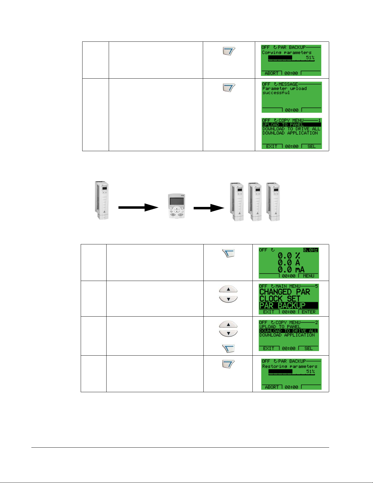
The text “Copying parameters” and a
progress diagram is displayed.
Select ABORT if you want to stop
4
the process.
The text “Parameter upload
successful” is displayed and the
control panel returns to the PAR
BACKUP menu. Select EXIT to
return to the main menu. Now you
can disconnect the panel.
5
• Download Full Set – Restores the full parameter set from the Control Panel to
the drive. Use this option to restore a drive, or to configure identical drives. This
download does not include user sets of parameters.
To download all parameters to drive, follow these steps:
Select MENU to enter the menu.
1
Select PAR BACKUP with the UP/
DOWN buttons.
2
Scroll to Download to drive all and
select SEL.
3
The text “Restoring parameters” is
displayed. Select ABORT if you want
to stop the process.
4
Control panel
Page 41
ACH550-UH User’s Manual 1-41
Upload
to panel
Download
application
IP2100
Control
X0202
IP2101
Panel
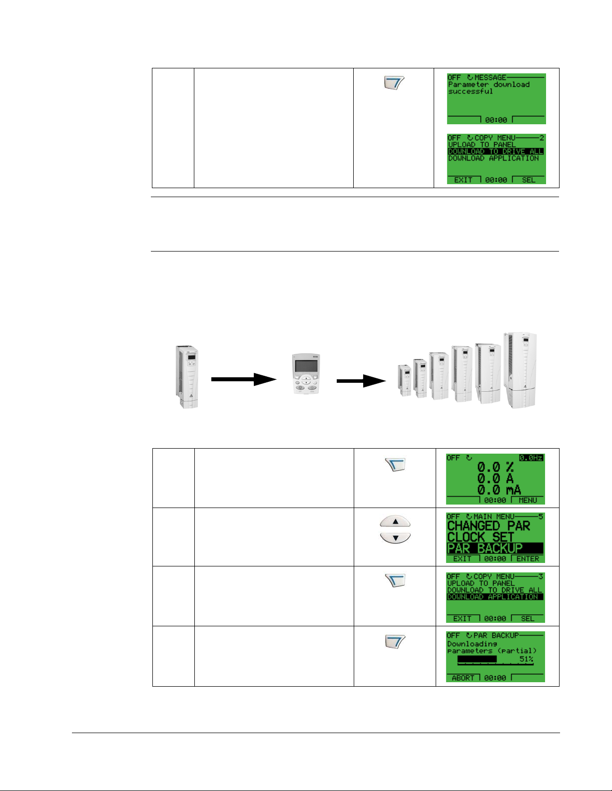
After the download stops, the
message “Parameter download
successful” is displayed and the
control panel goes back to PAR
BACKUP menu. Select EXIT to return
to the main menu.
5
Note: Download Full Set writes all parameters to the drive, including motor
parameters. Only use this function to restore a drive, or to transfer parameters to
systems that are identical to the original system.
• Download Application – Copies a partial parameter set from the Control Panel
to a drive. The partial set does not include internal motor parameters, parameters
9905…9909, 1605, 1607, 5201, nor any Group 51 and 53 parameters. Use this
option to transfer parameters to systems that use similar configurations – the
drive and motor sizes do not need to be the same.
To download application to drive, follow these steps:
Select MENU to enter the menu.
1
Select PAR BACKUP with the UP/
DOWN buttons.
2
Scroll to DOWNLOAD APPLICATION
and select SEL.
3
The text “Downloading parameters
(partial)” is displayed. Select ABORT
if you want to stop the process.
4
Control panel
Page 42

1-42 ACH550-UH User’s Manual
LOC DIFFERENCES ----
VALUES UNDER MIN
VALUES OVER MAX
INVALID VALUES
EXTRA PARS
MISSING VALUES
READY SEL
3
2
1
5
7
LOC DIFFERENCES ---VALUES UNDER MIN
VALUES OVER MAX
INVALID VALUES
EXTRA PARS
MISSING VALUES
READY SEL
3
2
1
5
7
LOC INVALID VAL
9902 APLIC MACRO
2606*SWITCHING FREQ
12 kHz
8 kHz
3401*DISP 1 SEL
EXIT EDIT
The text “Parameter download
successful” is displayed and the
control panel returns to PAR BACKUP
menu. Select EXIT to return to the
main menu.
5
• Download User Set 1 - Copies USER S1 parameters (user sets are saved using
parameter 9902
APPLIC MACRO) from the Control Panel to the drive.
• Download User Set 2 - Copies
USER S2 parameters from the Control Panel to the
drive.
Handling inexact downloads
In some situations, an exact copy of the download is not appropriate for the target
drive. Some examples:
• A download to an old drive specifies parameters/values that are not available on
the old drive.
• A download (from an old drive) to a new drive does not have definitions for the
new parameters – parameters that did not originally exist.
• A download can include an illegal value for the target drive, e.g. a backup from a
small drive can have a switching frequency of 12 kHz whereas a big drive can
only handle 8k Hz.
As a default, the control panel handles these situations by:
• Discarding parameters/values not available on
the target drive.
• Using parameter default values when the
download provides no values or invalid values.
• Providing a Differences List – A listing of the
type and number of items that the target cannot
accept exactly as specified.
You can either accept the default edits by pressing
READY, or view and edit each item as follows:
1. Highlight an item type in the Differences List (left screen below) and press SEL to
see the details for the selected type (right screen below).
Control panel
Page 43

ACH550-UH User’s Manual 1-43
In the above-right “details” screen:
• The first item that requires editing is automatically highlighted and includes
details: In general, the first item listed in the details is the value defined by the
backup file. The second item listed is the “default edit.”
• For tracking purposes, an asterisk initially appears by each item. As edits are
made, the asterisks disappear.
2. In the illustrated example, the backup specifies a switching frequency of 12 kHz, but
the target drive is limited to 8 kHz.
3. Press EDIT to edit the parameter. The display is the target drive’s standard edit
screen for the selected parameter.
4. Highlight the desired value for the target drive.
5. Press SAVE to save setting.
6. Press EXIT to step back to the differences view and continue for each remaining
exception.
7. When your editing is complete, press READY in the Differences List and then select
“Yes, save parameters.”
Download failures
In some situations, the drive may be unable to accept a download. In those cases,
the control panel display is: “Parameter download failed” plus one of the following
causes:
• Set not found – You are attempting to download a data set that was not defined in
the backup. The remedy is to manually define the set, or upload the set from a
drive that has the desired set definitions.
• Par lock – The remedy is to unlock the parameter set (parameter 1602).
• Incompat drive/model – The remedy is to perform backups only between drives of
the same type (ACS/industrial or ACH/HVAC) and the same model (all ACH550).
• Too many differences – The remedy is to manually define a new set, or upload the
set from a drive that more closely resembles the target drive.
Note: If upload or download of parameters is aborted, the partial parameter set is not
implemented.
Clock Set Mode
The Clock Set Mode is used for setting the time and date for the internal clock of the
ACH550. In order to use the timer functions of the ACH550, the internal clock has to
be set first. Date is used to determine weekdays and is visible in Fault logs.
Control panel
Page 44

1-44 ACH550-UH User’s Manual
To set the clock, follow these steps:
Select MENU to enter the main menu.
1
Scroll to Clock Set with the UP/DOWN
buttons and select ENTER to enter the
Clock Set Mode.
2
Scroll to Clock Visibility with the UP/
DOWN buttons and select SEL to change
the visibility of the clock.
3
Scroll to Show Clock with the UP/DOWN
buttons and select SEL to make the clock
visible.
4
Scroll to Set Time with the UP/DOWN
buttons and select SEL.
5
Change the hours and minutes with the
UP/DOWN buttons and select OK to save
the values. The active value is displayed
6
in inverted color.
Scroll to Time Format with the UP/DOWN
buttons and select SEL.
7
The different formats are displayed.
Select a format with the UP/DOWN
buttons and select SEL to confirm the
8
selection.
Scroll to Set Date with the UP/DOWN
buttons and select SEL.
Control panel
9
Page 45

ACH550-UH User’s Manual 1-45
Change the days, months and year with
the UP/DOWN buttons and select OK to
save the values. The active value is
10
displayed in inverted color.
Scroll to Date Format with the UP/DOWN
buttons and select SEL.
11
The Date formats are displayed. Select a
date format with the UP/DOWN buttons
and select OK to confirm the selection.
12
Select EXIT twice to return to the main
menu.
13
Control panel
Page 46

1-46 ACH550-UH User’s Manual
I/O Settings Mode
To view and edit the I/O settings, follow these steps:
Select MENU to enter the main menu.
1
Scroll to I/O Settings with the UP/DOWN
buttons and select ENTER.
2
Scroll to the I/O setting you want to view
with the UP/DOWN buttons and select
SEL.
3
Select the setting you want to view with
the UP/DOWN buttons and select OK.
4
You can change the value with the UP/
DOWN buttons and save it by selecting
SAVE.
5
If you do not want to change the setting,
select CANCEL.
Select EXIT to return to the main menu.
6
Control panel
Page 47

ACH550-UH User’s Manual 1-47
Start-up
Start-up
Start-up can be performed in two ways:
• Using the Start-Up Assistant.
• Changing the parameters individually.
Start-up by using the Start-Up Assistant
To start the Start-Up Assistant, follow these steps:
Select MENU to enter the main menu.
1
Select ASSISTANTS with the Up/Down
buttons and select ENTER.
2
Scroll to COMMISSION DRIVE with the
Up/Down buttons.
3
Change the values suggested by the
assistant to your preferences and then
press SAVE after every change.
4
The Start-Up Assistant will guide you through the start-up.
Start-up by changing the parameters individually
To change the parameters, follow these steps:
Select MENU to enter the main menu.
1
Select the Parameters mode with the UP/
DOWN buttons and select ENTER to
select the Parameters mode.
2
Start-up
Page 48
1-48 ACH550-UH User’s Manual
Select the appropriate parameter group
with the UP/DOWN buttons and select
SEL
3
Select the appropriate parameter in a
group with the UP/DOWN buttons. Select
EDIT to change the parameter value.
4
Press the UP/DOWN buttons to change
the parameter value.
5
Select SAVE to store the modified value or
select CANCEL to leave the set mode.
Any modifications not saved are
6
cancelled.
Select EXIT to return to the listing of
parameter groups, and again to return to
the main menu.
7
To complete the control connections by manually entering the parameters, see
Parameters Mode on page 1-35.
For detailed hardware description, see the Technical data section on page 1-299.
Note: The current parameter value appears below the highlighted parameter.
Note: To view the default parameter value, press the UP/DOWN buttons
simultaneously.
Note: The most typical and necessary parameters to change are parameter groups
99 Start-up data, 10 Start/Stop/Dir, 11 Reference Select, 20 Limits, 21 Start/Stop, 22
Accel/Decel, 26 Motor Control and 30 Fault Functions.
Note: To restore the default factory settings, select the application macro HVAC
Default.
Start-up
Page 49

ACH550-UH User’s Manual 1-49
Application macros
Overview
Macros change a group of parameters to new, predefined values designed for
specific applications. Use macros to minimize the need for manual editing of
parameters. Selecting a macro sets all other parameters to their default values,
except:
• Group 99: Start-up Data parameters (except parameter 9904)
• The
• The
• The
• The
PARAMETER LOCK 1602
PARAM SAVE 1607
COMM FAULT FUNC 3018 and COMM FAULT TIME 3019
COMM PROT SEL 9802
• Groups 51…53 serial communication parameters
• Group 29: Maintenance triggers
After selecting a macro, additional parameter changes can be made manually using
the control panel.
Application macros are enabled by setting the value for parameter 9902
MACRO. By default, HVAC Default (value 1) is the enabled macro.
APPLIC
General considerations
The following considerations apply for all macros:
• When using a direct speed reference in AUTO mode, connect the speed
reference to analog input 1 (AI1), and provide the START command using digital
input 1 (DI1). In HAND/OFF mode, the control panel provides the speed
reference and START command.
• When using process PID, connect the feedback signal to analog input 2 (AI2). As
a default, the control panel sets the Setpoint, but analog input 1 can be used as
an alternate source. You can set up process PID using parameters (Group 40) or
using the PID control assistant (recommended).
Application macros
Page 50
1-50 ACH550-UH User’s Manual
Application / macro listing
This section describes the following macros:
9902
Value
1 HVAC Default
2 Supply Fan
3 Return Fan
4 Cooling Tower Fan
5 Condenser
6Booster Pump
7 Pump Alternation
8 Internal Timer
Macro
Selecting an application macro
To select a macro, follow these steps:
Select MENU to enter the main menu.
1
Select ASSISTANTS with the UP/DOWN
buttons and select ENTER.
2
9902
Value
9 Internal Timer with Constant Speeds
10 Floating Point
11 Dual Setpoint PID
12 Dual Setpoint PID with Constant Speeds
13 E-bypass
14 Hand Control
15 E-Clipse
Macro
Scroll to APPLICATION and select
ENTER.
3
Select a macro with the UP/DOWN buttons
and select SAVE.
4
Restoring defaults
To restore the factory default settings, select the application macro HVAC Default.
Control wiring
Each macro has specific requirements for control wiring. For general details
about the ACH550 control wiring terminals, see Control terminal descriptions on
page 1-318. Specific wiring requirements are included with each macro description.
Application macros
Page 51
ACH550-UH User’s Manual 1-51
1SCR
2AI1
3AGND
410V
5AI2
6AGND
7AO1
8AO2
9AGND
10 24V
11 GND
12 DCOM
13 DI1
14 DI2
15 DI3
16 DI4
17 DI5
18 DI6
19 RO1C
20 RO1A
21 RO1B
22 RO2C
23 RO2A
24 RO2B
25 RO3C
26 RO3A
27 RO3B
External reference 0(2)…10 V or 0(4)…20 mA
Reference voltage 10 VDC
Output frequency: 0(4)…20 mA
Start/Stop: Activate to start drive
Not configured
Constant (Preset) speed 1 (P 1202)
Safety interlock: Deactivate to stop drive (P 1608)
Not configured
Relay output 1 (P 1401)
Default operation: Ready =>19 connected to 21
Relay output 2 (P 1402)
Default operation: Running =>22 connected to 24
Relay output 3 (P 1403)
Default operation: Fault (-1) =>25 connected to 27
X1
Output current: 0(4)…20 mA
Not configured
Analog input circuit common
PID feedback: 0(2)…10 V or 0(4)…20 mA
Analog output circuit common
Auxiliary voltage output +24 VDC
Auxiliary voltage output common
Digital input common for all
Signal cable shield (screen)
Analog input circuit common
(Fault => 25 connected to 26)
+
mA
mA
+
J1
AI1: 0(4)
…20 mA
AI2: 0(4)
…20 mA
ON
Jumper Settings
ON
1
2
ON
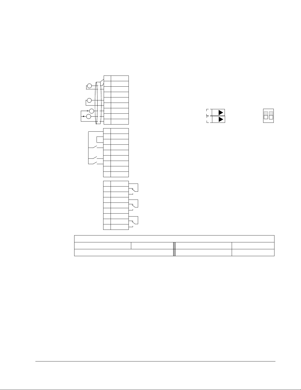
HVAC Default macro
This macro provides the factory default parameter settings for the ACH550-UH.
Factory defaults can be restored at any time by setting parameter 9902 to 1. The
diagram below shows typical wiring using this macro. When using direct speed
reference in AUTO mode or process PID, see General considerations on page 1-49.
None (Default macro)
Parameter Value
Parameters Changed Relative to HVAC Default
Parameter Value
Application macros
Page 52
1-52 ACH550-UH User’s Manual
1SCR
2AI1
3AGND
4 10V
5AI2
6AGND
7AO1
8AO2
9AGND
10 24V
11 GN D
12 DCOM
13 DI1
14 DI2
15 DI3
16 DI4
17 DI5
18 DI6
19 RO1C
20 RO1A
21 RO1B
22 RO2C
23 RO2A
24 RO2B
25 RO3C
26 RO3A
27 RO3B
X1
+
mA
mA
External reference 0(2)…10 V or 0(4)…20 mA
Reference voltage 10 VDC
Output frequency: 0(4)…20 mA
Start/Stop: Activate to start drive
Run permissive: Deactivate to stop drive (P 1601)
Constant (Preset) speed 1 (P 1202
1
)
Safety interlock 1: Deactivate to stop drive (P 1608)
Safety interlock 2: Deactivate to stop drive (P 1609)
Relay output 1 (P 1401)
Default operation: Started =>19 connected to 21
Relay output 2 (P 1402)
Default operation: Running =>22 connected to 24
Relay output 3 (P 1403)
Default operation: Fault (-1) =>25 connected to 27
Output current: 0(4)…20 mA
Not configured
Analog input circuit common
PID feedback: 0(2)…10 V or 0(4)…20 mA
Analog output circuit common
Auxiliary voltage output +24 VDC
Auxiliary voltage output common
Digital input common for all
Signal cable shield (screen)
Analog input circuit common
(Fault => 25 connected to 26)
+
J1
AI1: 0(4)
…20 mA
AI2: 0(4)
…20 mA
ON
Jumper Settings
ON
1
2
ON
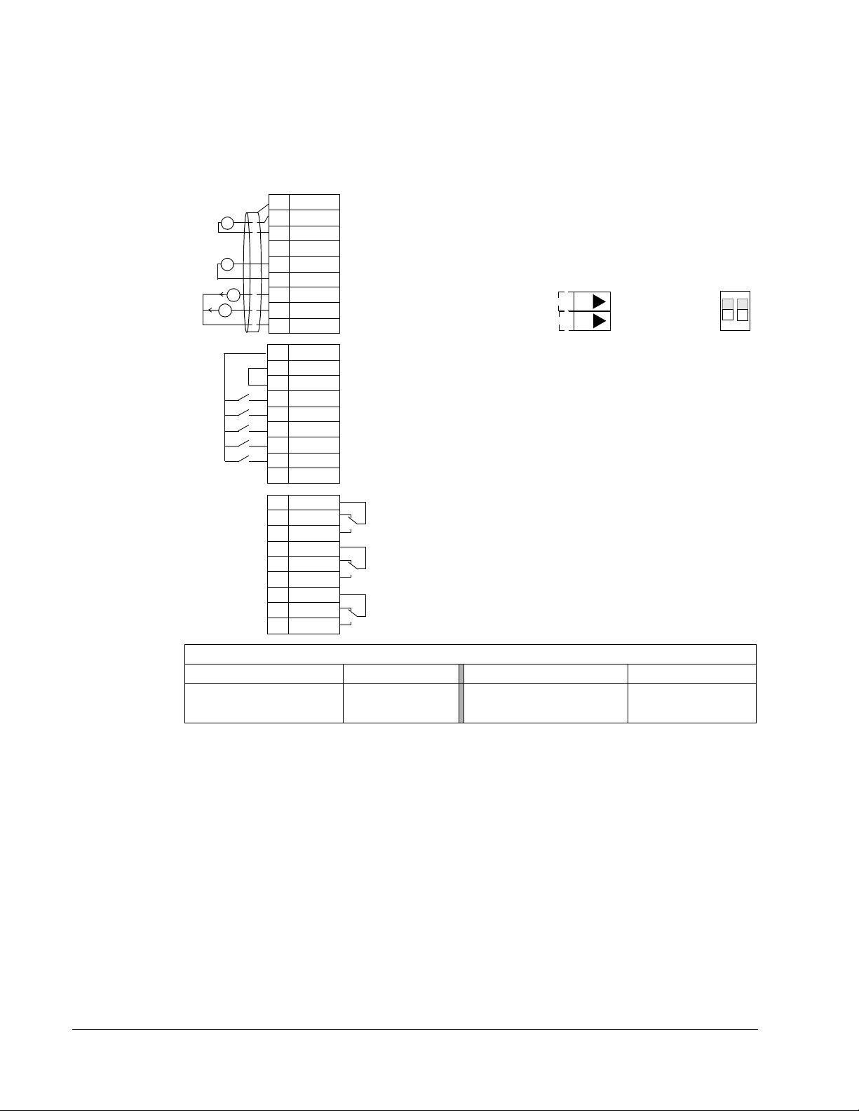
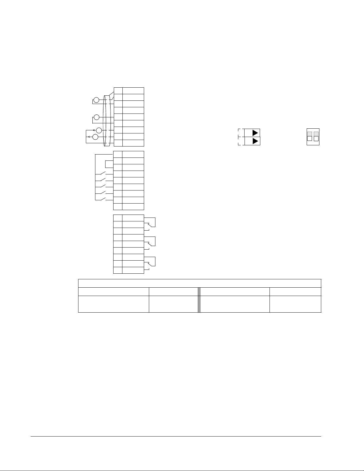
Supply Fan macro
This macro configures for supply fan applications where the supply fan brings fresh
air in according to signals received from a transducer. When using direct speed
reference in AUTO mode or process PID, see General considerations on page 1-49.
Application macros
Parameters Changed Relative to HVAC Default
9902
1401
Parameter Value Parameter Value
APPLIC MACRO 2 (SUPPLY FAN) 1601 RUN ENABLE 2 (DI2)
RELAY OUTPUT 17 (STARTED) 1609 START ENABLE 25 (DI5)
Page 53

ACH550-UH User’s Manual 1-53
1SCR
2AI1
3AGND
4 10V
5AI2
6AGND
7AO1
8AO2
9AGND
10 24V
11 GN D
12 DCOM
13 DI1
14 DI2
15 DI3
16 DI4
17 DI5
18 DI6
19 RO1C
20 RO1A
21 RO1B
22 RO2C
23 RO2A
24 RO2B
25 RO3C
26 RO3A
27 RO3B
X1
+
mA
mA
External reference 0(2)…10 V or 0(4)…20 mA
Reference voltage 10 VDC
Output frequency: 0(4)…20 mA
Start/Stop: Activate to start drive
Run permissive: Deactivate to stop drive (P 1601)
Constant (Preset) speed 1 (P 1202
1
)
Safety interlock 1: Deactivate to stop drive (P 1608)
Safety interlock 2: Deactivate to stop drive (P 1609)
Relay output 1 (P 1401)
Default operation: Started =>19 connected to 21
Relay output 2 (P 1402)
Default operation: Running =>22 connected to 24
Relay output 3 (P 1403)
Default operation: Fault (-1) =>25 connected to 27
Output current: 0(4)…20 mA
Not configured
Analog input circuit common
PID feedback: 0(2)…10 V or 0(4)…20 mA
Analog output circuit common
Auxiliary voltage output +24 VDC
Auxiliary voltage output common
Digital input common for all
Signal cable shield (screen)
Analog input circuit common
(Fault => 25 connected to 26)
+
J1
AI1: 0(4)
…20 mA
AI2: 0(4)
…20 mA
ON
Jumper Settings
ON
1
2
ON
Return Fan macro
This macro configures for return fan applications where the return fan removes air
according to signals received from a transducer. When using direct speed reference
in AUTO mode or process PID, see General considerations on page 1-49.
Parameters Changed Relative to HVAC Default
Parameter Value Parameter Value
APPLIC MACRO 3 (RETURN FAN) 1609 START ENABLE 25 (DI5)
9902
RELAY OUTPUT 17 (STARTED)
1401
Application macros
Page 54
1-54 ACH550-UH User’s Manual
1SCR
2AI1
3AGND
410V
5AI2
6AGND
7AO1
8AO2
9AGND
10 24V
11 GN D
12 DCOM
13 DI1
14 DI2
15 DI3
16 DI4
17 DI5
18 DI6
19 RO1C
20 RO1A
21 RO1B
22 RO2C
23 RO2A
24 RO2B
25 RO3C
26 RO3A
27 RO3B
X1
+
mA
mA
External reference 0(2)…10 V or 0(4)…20 mA
Reference voltage 10 VDC
Output frequency: 0(4)…20 mA
Start/Stop: Activate to start drive
Run permissive: Deactivate to stop drive (P 1601)
Constant (Preset) speed 1 (P 12021)
Safety interlock 1: Deactivate to stop drive (P 1608)
Safety interlock 2: Deactivate to stop drive (P 1609)
Relay output 1 (P 1401)
Default operation: Started =>19 connected to 21
Relay output 2 (P 1402)
Default operation: Running =>22 connected to 24
Relay output 3 (P 1403)
Default operation: Fault (-1) =>25 connected to 27
Output current: 0(4)…20 mA
Not configured
Analog input circuit common
PID feedback: 0(2)…10 V or 0(4)…20 mA
Analog output circuit common
Auxiliary voltage output +24 VDC
Auxiliary voltage output common
Digital input common for all
Signal cable shield (screen)
Analog input circuit common
(Fault => 25 connected to 26)
+
J1
AI1: 0(4)
…20 mA
AI2: 0(4)
…20 mA
ON
Jumper Settings
ON
1
2
ON
Cooling Tower Fan macro
This macro configures for cooling tower fan applications where the fan speed is
controlled according to the signals received from a transducer. When using direct
speed reference in AUTO mode or process PID, see General considerations on
page 1-49.
9902 APPLIC MACRO 4 (CLNG TWR FAN) 4005 ERROR VALUE INV 1 (YES)
2007
Parameter Value Parameter Value
MINIMUM FREQ 20.0 Hz
Parameters Changed Relative to HVAC Default
Application macros
Page 55
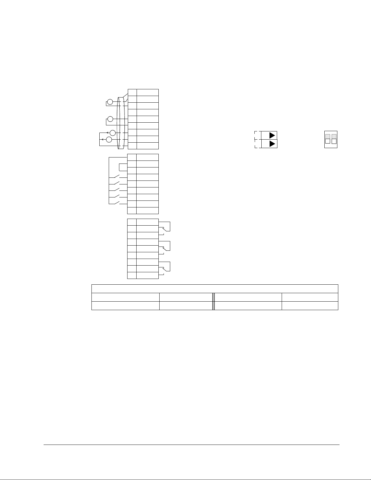
ACH550-UH User’s Manual 1-55
1SCR
2AI1
3AGND
410V
5AI2
6AGND
7AO1
8AO2
9AGND
10 24V
11 GN D
12 DCOM
13 DI1
14 DI2
15 DI3
16 DI4
17 DI5
18 DI6
19 RO1C
20 RO1A
21 RO1B
22 RO2C
23 RO2A
24 RO2B
25 RO3C
26 RO3A
27 RO3B
X1
+
mA
mA
External reference 0(2)…10 V or 0(4)…20 mA
Reference voltage 10 VDC
Output frequency: 0(4)…20 mA
Start/Stop: Activate to start drive
Run permissive: Deactivate to stop drive (P 1601)
Constant (Preset) speed 1 (P 12021)
Safety interlock 1: Deactivate to stop drive (P 1608)
Safety interlock 2: Deactivate to stop drive (P 1609)
Relay output 1 (P 1401)
Default operation: Started =>19 connected to 21
Relay output 2 (P 1402)
Default operation: Running =>22 connected to 24
Relay output 3 (P 1403)
Default operation: Fault (-1) =>25 connected to 27
Output current: 0(4)…20 mA
Not configured
Analog input circuit common
PID feedback: 0(2)…10 V or 0(4)…20 mA
Analog output circuit common
Auxiliary voltage output +24 VDC
Auxiliary voltage output common
Digital input common for all
Signal cable shield (screen)
Analog input circuit common
(Fault => 25 connected to 26)
+
J1
AI1: 0(4)
…20 mA
AI2: 0(4)
…20 mA
ON
Jumper Settings
ON
1
2
ON
Condenser macro
This macro configures for condenser and liquid cooler applications where fan speed
is controlled according to signals received from a transducer. When using direct
speed reference in AUTO mode or process PID, see General considerations on
page 1-49.
9902 APPLIC MACRO 5 (CONDENSER) 4005 ERROR VALUE INV 1 (YES)
Parameter Value Parameter Value
Parameters Changed Relative to HVAC Default
Application macros
Page 56
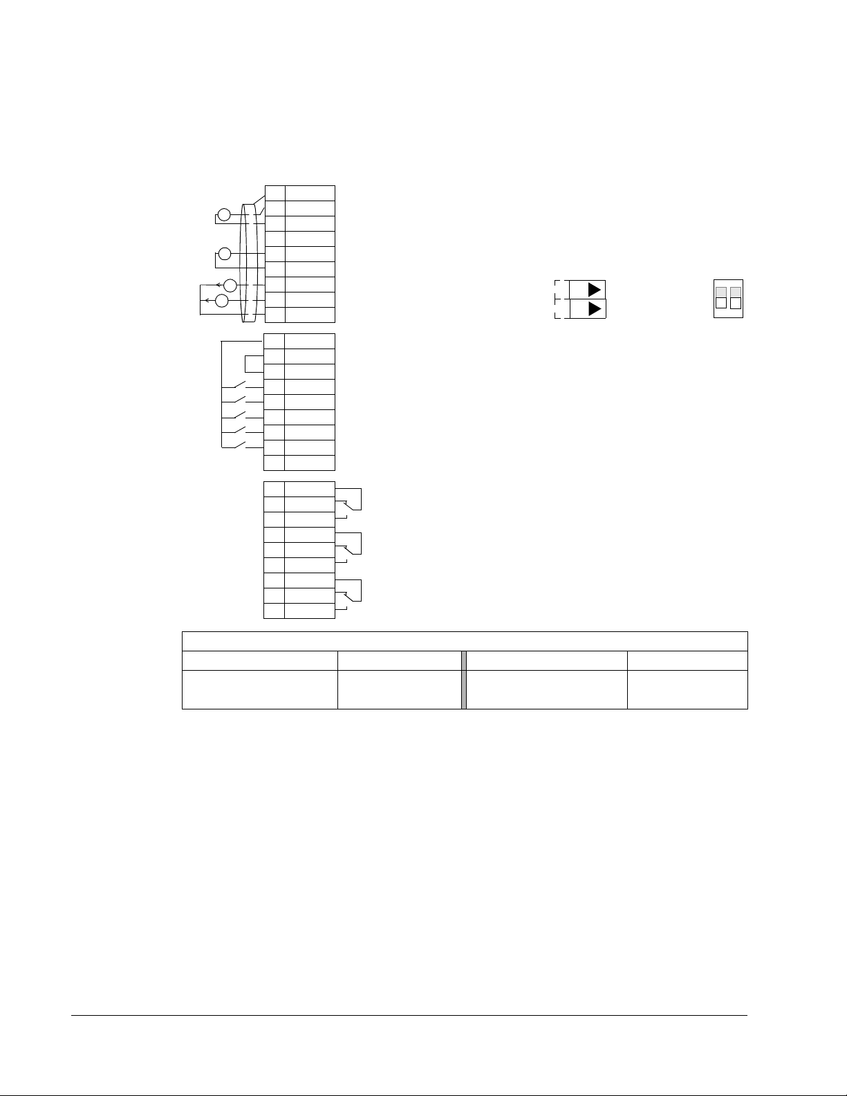
1-56 ACH550-UH User’s Manual
1SCR
2AI1
3AGND
410V
5AI2
6AGND
7AO1
8AO2
9AGND
10 24V
11 GN D
12 DCOM
13 DI1
14 DI2
15 DI3
16 DI4
17 DI5
18 DI6
19 RO1C
20 RO1A
21 RO1B
22 RO2C
23 RO2A
24 RO2B
25 RO3C
26 RO3A
27 RO3B
X1
+
mA
mA
External reference 0(2)…10 V or 0(4)…20 mA
Reference voltage 10 VDC
Output frequency: 0(4)…20 mA
Start/Stop: Activate to start drive
Run permissive: Deactivate to stop drive (P 1601)
Constant (Preset) speed 1 (P 12021)
Safety interlock 1: Deactivate to stop drive (P 1608)
Safety interlock 2: Deactivate to stop drive (P 1609)
Relay output 1 (P 1401)
Default operation: Started =>19 connected to 21
Relay output 2 (P 1402)
Default operation: Running =>22 connected to 24
Relay output 3 (P 1403)
Default operation: Fault (-1) =>25 connected to 27
Output current: 0(4)…20 mA
Not configured
Analog input circuit common
PID feedback: 0(2)…10 V or 0(4)…20 mA
Analog output circuit common
Auxiliary voltage output +24 VDC
Auxiliary voltage output common
Digital input common for all
Signal cable shield (screen)
Analog input circuit common
(Fault => 25 connected to 26)
+
J1
AI1: 0(4)
…20 mA
AI2: 0(4)
…20 mA
ON
Jumper Settings
ON
1
2
ON
Booster Pump macro
This macro configures for booster pump applications where the pump speed is
controlled according to a signal received from a transducer. When using direct speed
reference in AUTO mode or process PID, see General considerations on page 1-49.
Parameters Changed Relative to HVAC Default
9902
2101
Parameter Value Parameter Value
APPLIC MACRO 6 (BOOSTER PUMP) 2202 ACCELER TIME 110.0 s
START FUNCTION 8 (RAMP) 2203 DECELER TIME 110.0 s
Application macros
Page 57

ACH550-UH User’s Manual 1-57
1SCR
2AI1
3AGND
410V
5AI2
6AGND
7AO1
8AO2
9AGND
10 24V
11 GN D
12 DCOM
13 DI1
14 DI2
15 DI3
16 DI4
17 DI5
18 DI6
19 RO1C
20 RO1A
21 RO1B
22 RO2C
23 RO2A
24 RO2B
25 RO3C
26 RO3A
27 RO3B
X1
+
mA
mA
External reference 0(2)…10 V or 0(4)…20 mA
Reference voltage 10 VDC
Output frequency: 0(4)…20 mA
Start/Stop: Activate to start drive
Run permissive: Deactivate to stop drive (P 1601)
Not configured
PFA interlock 1: Deactivate to stop drive (P 1608)
PFA interlock 2: Deactivate to stop drive (P 1609)
Relay output 1 (P 1401)
Default operation: PFA (starts lag pump)
Relay output 2 (P 1402)
Default operation: Running =>22 connected to 24
Relay output 3 (P 1403)
Default operation: Fault (-1) =>25 connected to 27
Output current: 0(4)…20 mA
Not configured
Analog input circuit common
PID feedback: 0(2)…10 V or 0(4)…20 mA
Analog output circuit common
Auxiliary voltage output +24 VDC
Auxiliary voltage output common
Digital input common for all
Signal cable shield (screen)
Analog input circuit common
(Fault => 25 connected to 26)
+
J1
AI1: 0(4)
…20 mA
AI2: 0(4)
…20 mA
ON
Jumper Settings
ON
1
2
ON
Pump Alternation macro
This macro configures for pump alternation applications, usually used in booster
stations. To adjust/maintain pressure in the network, the speed of the one pump
changes according to a signal received from a pressure transducer. When the
variable speed pump reaches a maximum speed limit, auxiliary pumps start as
needed. When using process PID, see General considerations on page 1-49. To use
more than one (the default) Auxiliary pump, see parameter group 81.
9902
1201 CONST SPEED SEL 0 (NOT SEL) 8109 START FREQ 1 58.0 HZ
1401 RELAY OUTPUT 131 (PFA) 8110 START FREQ 2 58.0 HZ
1608 START ENABLE 10 (NOT SEL) 8111 START FREQ 3 58.0 HZ
2101 START FUNCTION 8 (RAMP) 8123 PFA ENABLE 1 (ACTIVE)
2202 ACCELER TIME 110.0 s
Parameter Value
APPLIC MACRO 7 (PUMP ALTERNA) 2203 DECELER TIME 1 10.0 s
Parameters Changed Relative to HVAC Default
Parameter Value
Application macros
Page 58

1-58 ACH550-UH User’s Manual
1SCR
2AI1
3AGND
410V
5AI2
6AGND
7AO1
8AO2
9AGND
10 24V
11 GN D
12 DCOM
13 DI1
14 DI2
15 DI3
16 DI4
17 DI5
18 DI6
19 RO1C
20 RO1A
21 RO1B
22 RO2C
23 RO2A
24 RO2B
25 RO3C
26 RO3A
27 RO3B
X1
+
mA
mA
External reference 0(2)…10 V or 0(4)…20 mA
Reference voltage 10 VDC
Output frequency: 0(4)…20 mA
Timer enable: Activate to start/stop drive from timer
Run permissive: Deactivate to stop drive (P 1601)
Timer override: Activate to start drive
Safety interlock 1: Deactivate to stop drive (P 1608)
Safety interlock 2: Deactivate to stop drive (P 1609)
Relay output 1 (P 1401)
Default operation: Started =>19 connected to 21
Relay output 2 (P 1402)
Default operation: Running =>22 connected to 24
Relay output 3 (P 1403)
Default operation: Fault (-1) =>25 connected to 27
Output current: 0(4)…20 mA
Not configured
Analog input circuit common
PID feedback: 0(2)…10 V or 0(4)…20 mA
Analog output circuit common
Auxiliary voltage output +24 VDC
Auxiliary voltage output common
Digital input common for all
Signal cable shield (screen)
Analog input circuit common
(Fault => 25 connected to 26)
+
J1
AI1: 0(4)
…20 mA
AI2: 0(4)
…20 mA
ON
Jumper Settings
ON
1
2
ON
Internal Timer macro
This macro configures for applications where a built-in timer starts and stops the
motor. When the variable speed pump reaches a maximum speed limit, auxiliary
pumps start as needed. When using direct speed reference in AUTO mode or
process PID, see General considerations on page 1-49.
Momentarily activating digital input 3 (DI3) provides a boost function which operates
the motor. See group 36, Timer Functions, for more information on setting up timers.
9902
1001 EXT1 COMMANDS 11 (TIMER 1) 1609 START ENABLE 25 (DI5)
1002 EXT2 COMMANDS 11 (TIMER 1) 3601 TIMERS ENABLE 1 (DI1)
1201
1401 RELAY OUTPUT 17 (STARTED) 3626 TIMER 1 SRC 31 (P1+2+3+4+B)
Parameter Value
APPLIC MACRO 8 (INT TIMER) 1601 RUN ENABLE 2 (DI2)
CONST SPEED SEL 0 (NOT SEL) 3622 BOOST SEL 3 (DI3)
Parameters Changed Relative to HVAC Default
Parameter Value
Application macros
Page 59

ACH550-UH User’s Manual 1-59
1SCR
2AI1
3AGND
410V
5AI2
6AGND
7AO1
8AO2
9AGND
10 24V
11 GN D
12 DCOM
13 DI1
14 DI2
15 DI3
16 DI4
17 DI5
18 DI6
19 RO1C
20 RO1A
21 RO1B
22 RO2C
23 RO2A
24 RO2B
25 RO3C
26 RO3A
27 RO3B
X1
+
mA
mA
External reference 0(2)…10 V or 0(4)…20 mA
Reference voltage 10 VDC
Output frequency: 0(4)…20 mA
Timer enable: Activate to start/stop drive from timer
Run permissive: Deactivate to stop drive (P 1601)
Timer override: Activate to start drive
Safety interlock 1: Deactivate to stop drive (P 1608)
Safety interlock 2: Deactivate to stop drive (P 1609)
Relay output 1 (P 1401)
Default operation: Started =>19 connected to 21
Relay output 2 (P 1402)
Default operation: Running =>22 connected to 24
Relay output 3 (P 1403)
Default operation: Fault (-1) =>25 connected to 27
Output current: 0(4)…20 mA
Not configured
Analog input circuit common
Not configured
Analog output circuit common
Auxiliary voltage output +24 VDC
Auxiliary voltage output common
Digital input common for all
Signal cable shield (screen)
Analog input circuit common
(Fault => 25 connected to 26)
J1
AI1: 0(4)
…20 mA
AI2: 0(4)
…20 mA
ON
Jumper Settings
ON
1
2
ON
Internal Timer with Constant Speeds / PRV macro
This macro configures for applications such as a timed powered roof ventilator
(PRV) which alternates between two constant speeds (constant speed 1 and 2)
based on a built-in timer.
Momentarily activating digital input 3 (DI3) provides a boost function which operates
the motor. See group 36, Timer Functions, for more information on setting up timers.
9902 APPLIC MACRO 9 (INT TIMER CS) 3417 SIGNAL 3 MAX 200.0%
1002 EXT2 COMMANDS 0 (NOT SEL) 3419 OUTPUT 3 UNIT 4 (%)
1103
1106 REF2 SEL 2 (AI2) 3421 OUTPUT 3 MAX 200.0%
1201 CONST SPEED SEL 15 (TIMER 1) 3601 TIMERS ENABLE 1 (DI1)
1401
1601 RUN ENABLE 2 (DI2) 3626 TIMER 1 SRC 31 (P1+2+3+4+B)
1609 START ENABLE 25 (DI5) 4010 SET POINT SEL 1 (AI1)
3415
3416
Parameter Value
REF1 SEL 0 (KEYPAD) 3420 OUTPUT 3 MIN -200.0%
RELAY OUTPUT 17 (STARTED) 3622 BOOST SEL 3 (DI3)
SIGNAL 3 PARAM 0105 (TORQUE) 4110 SET POINT SEL 1 (AI1)
SIGNAL 3 MIN -200.0%
Parameters Changed Relative to HVAC Default
Parameter Value
Application macros
Page 60

1-60 ACH550-UH User’s Manual
1SCR
2AI1
3AGND
410V
5AI2
6AGND
7AO1
8AO2
9AGND
10 24V
11 GN D
12 DCOM
13 DI1
14 DI2
15 DI3
16 DI4
17 DI5
18 DI6
19 RO1C
20 RO1A
21 RO1B
22 RO2C
23 RO2A
24 RO2B
25 RO3C
26 RO3A
27 RO3B
X1
mA
mA
Not configured
Reference voltage 10 VDC
Output frequency: 0(4)…20 mA
Start/Stop: Activate to start drive
Run permissive: Deactivate to stop drive (P 1601)
Constant (Preset) speed 1 (P 1202)
1
Safety interlock 1: Deactivate to stop drive (P 1608)
Reference up: Activate to increase reference
Relay output 1 (P 1401)
Default operation: Started =>19 connected to 21
Relay output 2 (P 1402)
Default operation: Running =>22 connected to 24
Relay output 3 (P 1403)
Default operation: Fault (-1) =>25 connected to 27
Output current: 0(4)…20 mA
Reference down: Activate to decrease reference
Analog input circuit common
Not configured
Analog output circuit common
Auxiliary voltage output +24 VDC
Auxiliary voltage output common
Digital input common for all
Signal cable shield (screen)
Analog input circuit common
(Fault => 25 connected to 26)
J1
AI1: 0(4)
…20 mA
AI2: 0(4)…20 mA
ON
Jumper Settings
ON
1
2
ON
Floating Point macro
This application macro is for applications where speed reference needs to be
controlled through digital inputs (DI5 & DI6). By activating digital input 5, the speed
reference increases, by activating digital input 6, the speed reference decreases. If
both digital inputs are active or inactive, the reference does not change.
Note: When constant speed 1 is activated using digital input 3 (DI3), the reference
speed is the value of parameter 1202. The value remains as the reference speed
when digital input 3 is deactivated.
Parameter Value Parameter Value
APPLIC MACRO 10 (FLOATING PNT) 3416 SIGNAL 3 MIN -200.0%
9902
1103 REF1 SEL 7 (DI5U, 6D) 3417 SIGNAL 3 MAX 200.0%
1401 RELAY OUTPUT 17 (STARTED) 3419 OUTPUT 3 UNIT 4 (%)
RUN ENABLE 2 (DI2) 3420 OUTPUT 3 MIN -200.0%
1601
3415 SIGNAL 3 PARAM 0105 (TORQUE) 3421 OUTPUT 3 MAX 200.0%
Parameters Changed Relative to HVAC Default
Application macros
Page 61

ACH550-UH User’s Manual 1-61
1SCR
2AI1
3AGND
410V
5AI2
6AGND
7AO1
8AO2
9AGND
10 24V
11 GN D
12 DCOM
13 DI1
14 DI2
15 DI3
16 DI4
17 DI5
18 DI6
19 RO1C
20 RO1A
21 RO1B
22 RO2C
23 RO2A
24 RO2B
25 RO3C
26 RO3A
27 RO3B
X1
+
mA
mA
External reference 0(2)…10 V or 0(4)…20 mA
Reference voltage 10 VDC
Output frequency: 0(4)…20 mA
Start/Stop: Activate to start drive
Run permissive: Deactivate to stop drive (P 1601)
Setpoint selection: Activate to select Set2
Safety interlock 1: Deactivate to stop drive (P 1608)
Safety interlock 2: Deactivate to stop drive (P 1609)
Relay output 1 (P 1401)
Default operation: Started =>19 connected to 21
Relay output 2 (P 1402)
Default operation: Running =>22 connected to 24
Relay output 3 (P 1403)
Default operation: Fault (-1) =>25 connected to 27
Output current: 0(4)…20 mA
Not configured
Analog input circuit common
PID feedback: 0(2)…10 V or 0(4)…20 mA
Analog output circuit common
Auxiliary voltage output +24 VDC
Common for DI return signals.
Auxiliary voltage output common
Signal cable shield (screen)
Analog input circuit common
(Fault => 25 connected to 26)
+
J1
AI1: 0(4)
…20 mA
AI2: 0(4)…20 mA
ON
Jumper Settings
ON
1
2
ON
Dual Setpoint with PID macro
This macro configures for dual setpoint PID applications, where activating digital
input 3 (DI3) changes the process PID controller’s setpoint to another value. When
using direct speed reference in AUTO mode or process PID, see General
considerations on page 1-49. Set process PID setpoints (internal to the drive) using
parameters 4011 (
SET1) and 4111 (SET2).
9902 APPLIC MACRO 11 (DUAL SETPPID) 4010 SET POINT SEL 19 (INTERNAL)
1201
1401
1601 RUN ENABLE 2 (DI2) 4110 SET POINT SEL 19 (INTERNAL)
1609 START ENABLE 25 (DI5) 4111 INTERNAL SETPNT 100.0%
Parameter Value
CONST SPEED SEL 0 (NOT SEL) 4011 INTERNAL SETPNT 50.0%
RELAY OUTPUT 17 (STARTED) 4027 PID 1 PARAM SET 3 (DI3)
Parameters Changed Relative to HVAC Default
Parameter Value
Application macros
Page 62

1-62 ACH550-UH User’s Manual
1SCR
2AI1
3AGND
410V
5AI2
6AGND
7AO1
8AO2
9AGND
10 24V
11 GN D
12 DCOM
13 DI1
14 DI2
15 DI3
16 DI4
17 DI5
18 DI6
19 RO1C
20 RO1A
21 RO1B
22 RO2C
23 RO2A
24 RO2B
25 RO3C
26 RO3A
27 RO3B
X1
+
mA
mA
External reference 0(2)…10 V or 0(4)…20 mA
Reference voltage 10 VDC
Output frequency: 0(4)…20 mA
Start/Stop: Activate to start drive
Presets/PID selection: Activate to select PID
Setpoint selection: Activate to select Set2
Preset speed 1
Preset speed 2
Relay output 1 (P 1401)
Default operation: Started =>19 connected to 21
Relay output 2 (P 1402)
Default operation: Running =>22 connected to 24
Relay output 3 (P 1403)
Default operation: Fault (-1) =>25 connected to 27
Output current: 0(4)…20 mA
Not configured
Analog input circuit common
PID feedback: 0(2)…10 V or 0(4)…20 mA
Analog output circuit common
Auxiliary voltage output +24 VDC
Auxiliary voltage output common
Digital input common for all
Signal cable shield (screen)
Analog input circuit common
(Fault => 25 connected to 26)
+
J1
AI1: 0(4)
…20 mA
AI2: 0(4)
…20 mA
ON
Jumper Settings
ON
1
2
ON
Dual Setpoint with PID and Constant Speeds
This macro configures for applications with 2 constant speeds, active PID and PID
alternating between two setpoints using digital inputs. Set PID setpoints (internal to
the drive) using parameters 4011 (
selects the setpoints.
SET1) and 4111 (SET2). The digital input DI3
9902 APPLIC MACRO 12 (DL SP PID CS) 4010 SET POINT SEL 19 (INTERNAL)
1102
1201 CONST SPEED SEL 10 (DI4, 5) 4027 PID 1 PARAM SET 3 (DI3)
1608 START ENABLE 10 (NOT SEL) 4110 SET POINT SEL 19 (INTERNAL)
2108
Parameter Value Parameter Value
EXT1/EXT2 SEL 2 (DI2) 4011 INTERNAL SETPNT 50.0%
START INHIBIT 1 (ON) 4111 INTERNAL SETPNT 100.0%
Parameters Changed Relative to HVAC Default
Application macros
Page 63

ACH550-UH User’s Manual 1-63
1SCR
2AI1
3AGND
410V
5AI2
6AGND
7AO1
8AO2
9AGND
10 24V
11 GN D
12 DCOM
13 DI1
14 DI2
15 DI3
16 DI4
17 DI5
18 DI6
19 RO1C
20 RO1A
21 RO1B
22 RO2C
23 RO2A
24 RO2B
25 RO3C
26 RO3A
27 RO3B
X1
+
mA
mA
External reference 0(2)…10 V or 0(4)…20 mA
Reference voltage 10 VDC
Output frequency: 0(4)…20 mA
Start/Stop: Activate to start drive
Run enable: Deactivate to stop drive (P 1601)
Not configured
Not configured
Not configured
Relay output 1 (P 1401)
Default operation: Started =>19 connected to 21
Relay output 2 (P 1402)
Default operation: Running =>22 connected to 24
Relay output 3 (P 1403)
Default operation: Fault (-1) =>25 connected to 27
Output current: 0(4)…20 mA
Not configured
Analog input circuit common
PID feedback: 0(2)…10 V or 0(4)…20 mA
Analog output circuit common
Auxiliary voltage output +24 VDC
Auxiliary voltage output common
Digital input common for all
Signal cable shield (screen)
Analog input circuit common
(Fault => 25 connected to 26)
+
J1
AI1: 0(4)
…20 mA
AI2: 0(4)
…20 mA
ON
Jumper Settings
ON
1
2
ON
E-bypass macro
This macro configures for an E-bypass device which can bypass the drive and
connect the motor direct on-line. When using direct speed reference in AUTO mode
or process PID, see General considerations on page 1-49.
Parameters Changed Relative to HVAC Default
9902
1201
1401
Parameter Value Parameter Value
APPLIC MACRO 13 (E-BYPASS) 1601 RUN ENABLE 2 (DI2)
CONST SPEED SEL 0 (NOT SEL) 1608 START ENABLE 10 (NOT SEL)
RELAY OUTPUT 17 (STARTED)
Application macros
Page 64
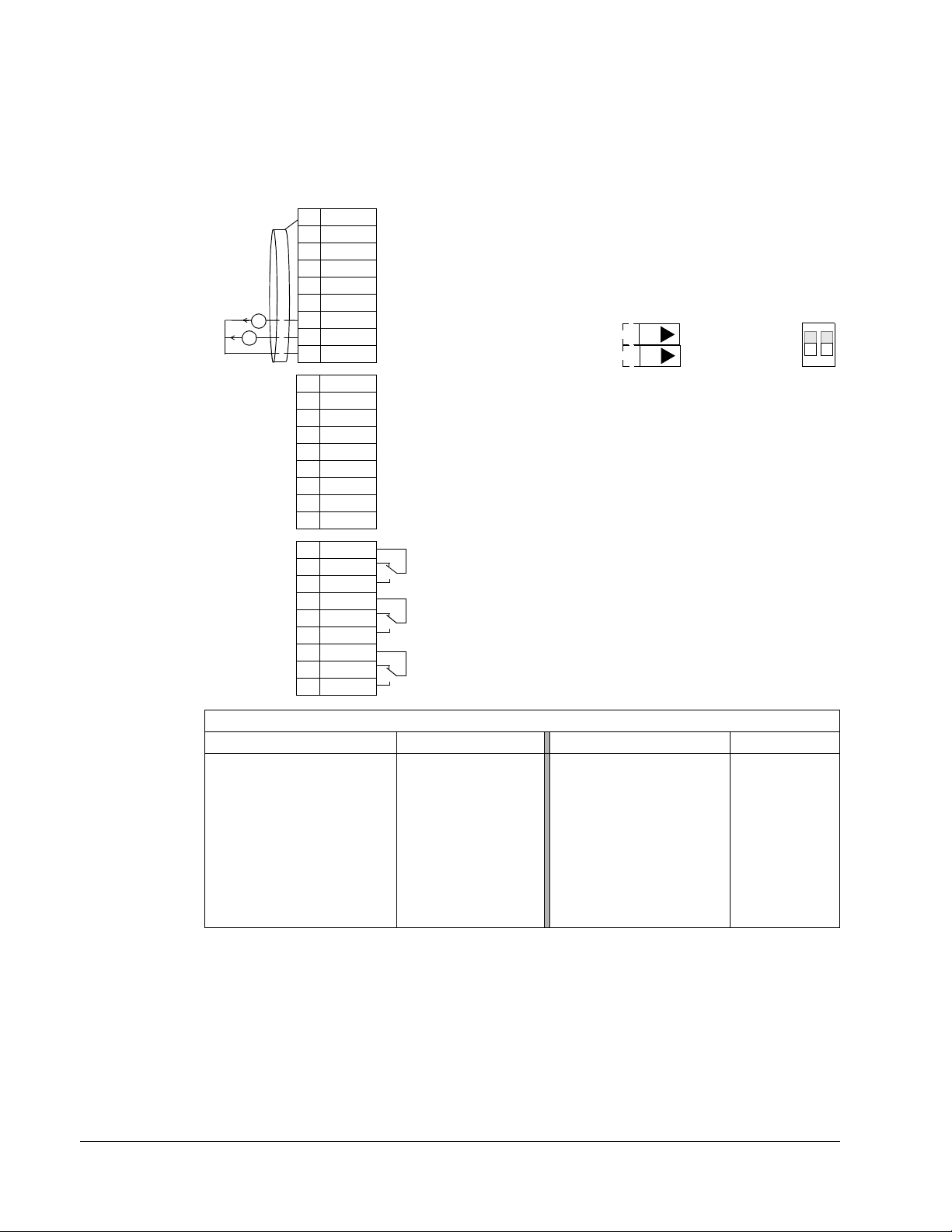
1-64 ACH550-UH User’s Manual
1SCR
2AI1
3AGND
410V
5AI2
6AGND
7AO1
8AO2
9AGND
10 24V
11 GN D
12 DCOM
13 DI1
14 DI2
15 DI3
16 DI4
17 DI5
18 DI6
19 RO1C
20 RO1A
21 RO1B
22 RO2C
23 RO2A
24 RO2B
25 RO3C
26 RO3A
27 RO3B
X1
mA
mA
Not configured
Reference voltage 10 VDC
Output frequency: 0(4)…20 mA
Not configured
Not configured
Not configured
Not configured
Not configured
Relay output 1 (P 1401)
Default operation: Started =>19 connected to 21
Relay output 2 (P 1402)
Default operation: Running =>22 connected to 24
Relay output 3 (P 1403)
Default operation: Fault (-1) =>25 connected to 27
Output current: 0(4)…20 mA
Not configured
Analog input circuit common
Not configured
Analog output circuit common
Auxiliary voltage output +24 VDC
Auxiliary voltage output common
Digital input common for all
Signal cable shield (screen)
Analog input circuit common
(Fault => 25 connected to 26)
J1
AI1: 0(4)
…20 mA
AI2: 0(4)
…20 mA
ON
Jumper Settings
ON
1
2
ON
Hand Control macro
This macro configures for drive control using only the control panel with no
automated control. Typically, this is a temporary configuration used prior to control
wiring.
Parameters Changed Relative to HVAC Default
9902
1001
1002
1106
1201 CONST SPEED SEL 0 (NOT SEL) 3420 OUTPUT 3 MIN 0.0
1504 MINIMUM AO1 0.0 mA 3421 OUTPUT 3 MAX 0.0
1510
1608 START ENABLE 10 (NOT SEL) 4110 SET POINT SEL 1 (AI1)
Parameter Value Parameter Value
APPLIC MACRO 14 (HAND CONTROL) 3415 SIGNAL 3 PARAM 0 (NOT SEL)
EXT1 COMMANDS 0 (NOT SEL) 3416 SIGNAL 3 MIN 0
EXT2 COMMANDS 0 (NOT SEL) 3417 SIGNAL 3 MAX 0
REF2 SEL 2 (AI2) 3419 OUTPUT 3 UNIT NO UNIT
MINIMUM AO2 0.0 mA 4010 SET POINT SEL 1 (AI1)
Application macros
Page 65
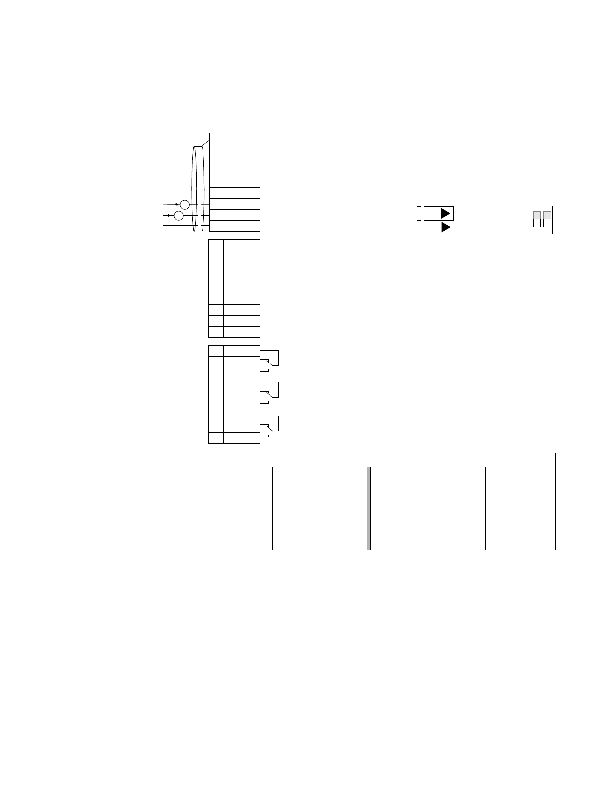
ACH550-UH User’s Manual 1-65
1SCR
2AI1
3AGND
410V
5AI2
6AGND
7AO1
8AO2
9AGND
10 24V
11 GN D
12 DCOM
13 DI1
14 DI2
15 DI3
16 DI4
17 DI5
18 DI6
19 RO1C
20 RO1A
21 RO1B
22 RO2C
23 RO2A
24 RO2B
25 RO3C
26 RO3A
27 RO3B
X1
mA
mA
Not configured
Reference voltage 10 VDC
Output frequency: 0(4)…20 mA
Not configured
Not configured
Not configured
Not configured
Not configured
Relay output 1 (P 1401)
Default operation: Started =>19 connected to 21
Relay output 2 (P 1402)
Default operation: Running =>22 connected to 24
Relay output 3 (P 1403)
Default operation: Fault (-1) =>25 connected to 27
Output current: 0(4)…20 mA
Not configured
Analog input circuit common
Not configured
Analog output circuit common
Auxiliary voltage output +24 VDC
Auxiliary voltage output common
Digital input common for all
Signal cable shield (screen)
Analog input circuit common
(Fault => 25 connected to 26)
J1
AI1: 0(4)
…20 mA
AI2: 0(4)
…20 mA
ON
Jumper Settings
ON
1
2
ON
E-Clipse macro
This macro configures for an E-Clipse Bypass device which can bypass the drive
and connect the motor direct on-line. When using direct speed reference in AUTO
mode or process PID, see General considerations on page 1-49.
Parameters Changed Relative to HVAC Default
9902
1001
1002 EXT2 COMMANDS 10 (COMM) 5304 EFB PARITY 2 (8 EVEN 1)
1201
1601 RUN ENABLE 7 (COMM)
Parameter Value Parameter Value
APPLIC MACRO 15 (E-CLIPSE) 1608 START ENABLE 17 (COMM)
EXT1 COMMANDS 10 (COMM) 5303 EFB BAUD RATE 76.8 KB/S
CONST SPEED SEL 0 (NOT SEL) 5305 EFB CTRL PROFILE 1 (DCU PROFILE)
Application macros
Page 66

1-66 ACH550-UH User’s Manual
Application macros
Page 67

ACH550-UH User’s Manual 1-67
Parameters
Complete parameter list
The following table lists all parameters. Table header abbreviations are:
= Parameters can be modified only when the drive is stopped.
•S
• User = Space to enter desired parameter values.
Code Name Range Resolution Default User S
Group 99: START-UP DATA
9901
9902 APPLIC MACRO -3…15, 31 1 1 (HVAC DEFAULT)
9904 MOTOR CTRL MODE 1, 3 1 3 (SCALAR:FREQ)
9905
9906
9907 MOTOR NOM FREQ 10.0…500.0 Hz 0.1 Hz 60.0 Hz (US)
9908 MOTOR NOM SPEED 50…30000 rpm 1 rpm Size dependent
9909
9910 ID RUN 0, 1 1 0 (OFF/IDMAGN)
9915 MOTOR COSPHI 0.01…0.97 0.01 0 (IDENTIFIED)
Group 01: OPERATING DATA
0101 SPEED & DIR -30000…30000 rpm 1 rpm 0102 SPEED 0…30000 rpm 1 rpm 0103
0104 CURRENT 0.0…1.5 · I
0105 TORQUE -200.0…200.0% 0.1% 0106
0107 DC BUS VOLTAGE 0…2.5 · V
0109
0110
0111 EXTERNAL REF 1 0.0…500.0 Hz / 0…30000 rpm 0.1 Hz / 1 rpm 0112 EXTERNAL REF 2 0.0…100.0% (0.0…600.0% for torque) 0.1% 0113
0114
0115
0116
0118
0119
0120
0121 AI 2 0.0…100.0% 0.1% 0122
LANGUAGE 0…16 1 0 (ENGLISH)
MOTOR NOM VOLT 115…345 V (200 V, US) 1 V 230 V (US)
230…690 V (400 V, US) 460 V (US)
288…862 V (600 V, US) 575 V (US)
MOTOR NOM CURR 0.15 · I
MOTOR NOM POWER 0.15…1.5 · P
OUTPUT FREQ 0.0…500.0 Hz 0.1 Hz -
POWER -1.5…1.5 · P
OUTPUT VOLTAGE 0…2.0 · V
DRIVE TEMP 0.0…150.0 °C0.1°C-
CTRL LOCATION 0…2 1 -
RUN TIME (R) 0…9999 h 1 h -
KWH COUNTER (R) 0…65535 kWh 1 kWh -
APPL BLK OUTPUT 0.0…100.0% (0.0…600.0% for torque) 0.1% -
DI 1-3 STATUS 000…111 (0…7 decimal) 1 -
DI 4-6 STATUS 000…111 (0…7 decimal) 1 -
AI 1 0.0…100.0% 0.1% -
RO 1-3 STATUS 000…111 (0…7 decimal) 1 -
… 1.5 · I
2n
2n
dN
dN
2n
n
0.1 A 1.0 · I
0.1 hp 1.0 · P
2n
n
0.1 A -
n
0.1 kW 1V 1V -
Parameters
Page 68

1-68 ACH550-UH User’s Manual
Code Name Range Resolution Default User S
0123 RO 4-6 STATUS 000…111 (0…7 decimal) 1 0124
0125 AO 2 0.0…20.0 mA 0.1 mA 0126 PID 1 OUTPUT -1000.0…1000.0% 0.1% 0127
0128
0129
0130
0131
0132
0133
0134
0135 COMM VALUE 1 -32768…+32767 1 0136
0137 PROCESS VAR 1- 1 0138 PROCESS VAR 2- 1 0139
0140 RUN TIME 0.00…499.99 kh 0.01 kh 0141 MWH COUNTER 0…65535 MWh 1 MWh 0142
0143 DRIVE ON TIME HI 0…65535 days 1 day 0144 DRIVE ON TIME LO 00:00:00…23:59:58 1 = 2 s 0145
0150
0153
0158 PID COMM VALUE 1 -32768 …+32767 1 0159
0174
0175 SAVED MWH 0…65535 MWh 1 MWh 0176 SAVED AMOUNT 1 0.0…999.9 0.1 0177
0178
Group 03: FB ACTUAL SIGNALS
0301
0302
0303
0304
0305 FAULT WORD 1- 1 0306
AO 1 0.0…20.0 mA 0.1 mA -
PID 2 OUTPUT -100.0…100.0% 0.1% -
PID 1 SETPNT Unit and scale defined by par. 4006/
--
4106 and 4007/4107
PID 2 SETPNT Unit and scale defined by par. 4206 and
--
4207
PID 1 FBK Unit and scale defined by par. 4006/
--
4106 and 4007/4107
PID 2 FBK Unit and scale defined by par. 4206 and
--
4207
PID 1 DEVIATION Unit and scale defined by par. 4006/
--
4106 and 4007/4107
PID 2 DEVIATION Unit and scale defined by par. 4206 and
--
4207
COMM RO WORD 0…65535 1 -
COMM VALUE 2 -32768…+32767 1 -
PROCESS VAR 3- 1 -
REVOLUTION CNTR 0…65535 Mrev 1 Mrev -
MOTOR TEMP Par. 3501 = 1…3: -10…200 °C
1Par. 3501 = 4: 0…5000 ohm
Par. 3501 = 5…6: 0…1
CB TEMP -20.0…150.0 °C 1.0 °C -
MOT THERM STRESS 0.0…100.0% 0.1% -
PID COMM VALUE 2 -32768 …+32767 1 -
SAVED KWH 0.0…999.9 kWh 0.1 kWh -
SAVED AMOUNT 2 0…65535 1 -
SAVED CO2 0.0…6553.5 tn 0.1 tn -
FB CMD WORD 1- 1 -
FB CMD WORD 2- 1 -
FB STS WORD 1- 1 -
FB STS WORD 2- 1 -
FAULT WORD 2- 1 -
Parameters
Page 69

ACH550-UH User’s Manual 1-69
Code Name Range Resolution Default User S
0307 FAULT WORD 3- 1 0308
0309 ALARM WORD 2- 1 -
Group 04: FAULT HISTORY
0401
0402
0403 FAULT TIME 2 Time hh.mm.ss 2 s 0
0404
0405
0406 VOLTAGE AT FLT 0.0…6553.5 0.1 V 0
0407
0408 TORQUE AT FLT -3276.8…+3276.7 0.1% 0
0409 STATUS AT FLT 0000…FFFF hex 1 0
0410
0411
0412 PREVIOUS FAULT 1 As par. 0401 1 0
0413
Group 10: START/STOP/DIR
1001 EXT1 COMMANDS 0…14 1 1 (DI1)
1002
1003 DIRECTION 0…3 1 1 (FORWARD)
Group 11: REFERENCE SELECT
1101
1102 EXT1/EXT2 SEL -6…12 1 0 (EXT1)
1103 REF1 SELECT 0…17, 20…21 1 1 (AI1)
1104
1105 REF1 MAX 0.0…500.0 Hz / 0…30000 rpm 0.1 Hz / 1 rpm 60.0 Hz (US) /
1106
1107 REF2 MIN 0.0…100.0% (0.0…600.0% for torque) 0.1% 0.0%
1108
Group 12: CONSTANT SPEEDS
1201
1202
1203 CONST SPEED 2 0.0…500.0 Hz / 0…30000 rpm 0.1 Hz / 1 rpm 12.0 Hz / 720 rpm (US)
1204 CONST SPEED 3 0.0…500.0 Hz / 0…30000 rpm 0.1 Hz / 1 rpm 18.0 Hz / 1080 rpm
1205
1206
1207
1208
1209
ALARM WORD 1- 1 -
LAST FAULT Fault codes (panel displays as text) 1 0
FAULT TIME 1 Date dd.mm.yy / power-on time in days 1 day 0
SPEED AT FLT -32768…+32767 1 rpm 0
FREQ AT FLT -3276.8…+3276.7 0.1 Hz 0
CURRENT AT FLT 0.0…6553.5 0.1 A 0
DI 1-3 AT FLT 000…111 (0…7 decimal) 1 0
DI 4-6 AT FLT 000…111 (0…7 decimal) 1 0
PREVIOUS FAULT 2 As par. 0401 1 0
EXT2 COMMANDS 0…14 1 1 (DI1)
KEYPAD REF SEL 1, 2 1 1 [REF1(Hz/rpm)]
REF1 MIN 0.0…500.0 Hz / 0…30000 rpm 0.1 Hz / 1 rpm 0.0 Hz / 0 rpm
1800 rpm (US)
REF2 SELECT 0…17, 19…21 1 19 (PID1OUT)
REF2 MAX 0.0…100.0% (0.0…600.0% for torque) 0.1% 100.0%
CONST SPEED SEL -14 …19 1 3 (DI3)
CONST SPEED 1 0.0…500.0 Hz / 0…30000 rpm 0.1 Hz / 1 rpm 6.0 Hz / 360 rpm (US)
(US)
CONST SPEED 4 0.0…500.0 Hz / 0…30000 rpm 0.1 Hz / 1 rpm 24.0 Hz / 1440 rpm
(US)
CONST SPEED 5 0.0…500.0 Hz / 0…30000 rpm 0.1 Hz / 1 rpm 30.0 Hz / 1800 rpm
(US)
CONST SPEED 6 0.0…500.0 Hz / 0…30000 rpm 0.1 Hz / 1 rpm 48.0 Hz / 2880 rpm
(US)
CONST SPEED 7 0.0…500.0 Hz / 0…30000 rpm 0.1 Hz / 1 rpm 60.0 Hz / 3600 rpm
(US)
TIMED MODE SEL 1, 2 1 2 (CS1/2/3/4)
Parameters
Page 70

1-70 ACH550-UH User’s Manual
Code Name Range Resolution Default User S
Group 13: ANALOG INPUTS
1301
1302 MAXIMUM AI1 0.0…100.0% 0.1% 100.0%
1303 FILTER AI1 0.0…10.0 s 0.1 s 0.1 s
1304
1305
1306 FILTER AI2 0.0…10.0 s 0.1 s 0.1 s
Group 14: RELAY OUTPUTS
1401
1402 RELAY OUTPUT 2 0…47 1 2 (RUN)
1403
1404 RO 1 ON DELAY 0.0…3600.0 s 0.1 s 0.0 s
1405 RO 1 OFF DELAY 0.0…3600.0 s 0.1 s 0.0 s
1406
1407
1408 RO 3 ON DELAY 0.0…3600.0 s 0.1 s 0.0 s
1409
1410 RELAY OUTPUT 4 0…47 1 0 (NOT SEL)
1411 RELAY OUTPUT 5 0…47 1 0 (NOT SEL)
1412
1413 RO 4 ON DELAY 0.0…3600.0 s 0.1 s 0.0 s
1414 RO 4 OFF DELAY 0.0…3600.0 s 0.1 s 0.0 s
1415
1416 RO 5 OFF DELAY 0.0…3600.0 s 0.1 s 0.0 s
1417 RO 6 ON DELAY 0.0…3600.0 s 0.1 s 0.0 s
1418
Group 15: ANALOG OUTPUTS
1501 AO1 CONTENT SEL 99…178 1 103 (OUTPUT FREQ)
1502
1503 AO1 CONTENT MAX Depends on selection - 60.0 Hz
1504 MINIMUM AO1 0.0…20.0 mA 0.1 mA 4.0 mA
1505
1506 FILTER AO1 0.0…10.0 s 0.1 s 0.1 s
1507 AO2 CONTENT SEL 99…178 1 104 (CURRENT)
1508
1509
1510 MINIMUM AO2 0.0…20.0 mA 0.1 mA 4.0 mA
1511
1512
Group 16: SYSTEM CONTROLS
1601
1602
1603
1604
1605 USER PAR SET CHG -6…6 1 0 (NOT SEL)
MINIMUM AI1 0.0…100.0% 0.1% 20.0%
MINIMUM AI2 0.0…100.0% 0.1% 20.0%
MAXIMUM AI2 0.0…100.0% 0.1% 100.0%
RELAY OUTPUT 1 0…47 1 1 (READY)
RELAY OUTPUT 3 0…47 1 3 [FAULT(-1)]
RO 2 ON DELAY 0.0…3600.0 s 0.1 s 0.0 s
RO 2 OFF DELAY 0.0…3600.0 s 0.1 s 0.0 s
RO 3 OFF DELAY 0.0…3600.0 s 0.1 s 0.0 s
RELAY OUTPUT 6 0…47 1 0 (NOT SEL)
RO 5 ON DELAY 0.0…3600.0 s 0.1 s 0.0 s
RO 6 OFF DELAY 0.0…3600.0 s 0.1 s 0.0 s
AO1 CONTENT MIN Depends on selection - 0.0 Hz
MAXIMUM AO1 0.0…20.0 mA 0.1 mA 20.0 mA
AO2 CONTENT MIN Depends on selection - 0.0 A
AO2 CONTENT MAX Depends on selection - 1.0 · I
MAXIMUM AO2 0.0…20.0 mA 0.1 mA 20.0 mA
FILTER AO2 0.0…10.0 s 0.1 s 0.1 s
RUN ENABLE -6…7 1 0 (NOT SEL)
PARAMETER LOCK 0…2 1 1 (OPEN)
PASS CODE 0…65535 1 0
FAULT RESET sEL -6…8 1 0 (KEYPAD)
2n
A
Parameters
Page 71

ACH550-UH User’s Manual 1-71
Code Name Range Resolution Default User S
1606 LOCAL LOCK -6…8 1 0 (NOT SEL)
1607
1608 START ENABLE 1 -6…7 1 4 (DI4)
1609 START ENABLE 2 -6…7 1 0 (NOT SEL)
1610
1611
Group 17: OVERRIDE
1701
1702
1703 OVERRIDE SPEED -30.000…30.000 rpm 1 0 rpm
1704
1705 OVERRIDE ENABLE 0…1 1 0 (OFF)
1706 OVERRIDE DIR -6...7 1 0 (FORWARD)
1707
Group 20: LIMITS
2001 MINIMUM SPEED -30000…30000 rpm 1 rpm 0 rpm
2002
2003 MAX CURRENT 0… 1.3 · I
2006 UNDERVOLT CTRL 0…2 1 1 [ENABLE(TIME)]
2007
2008 MAXIMUM FREQ 0.0…500.0 Hz 0.1 Hz 60.0 Hz (US)
2013 MIN TORQUE SEL -6…7 1 0 (MIN TORQUE 1)
2014
2015 MIN TORQUE 1 -600.0…0.0% 0.1% -300.0%
2016 MIN TORQUE 2 -600.0…0.0% 0.1% -300.0%
2017
2018 MAX TORQUE 2 0.0…600.0% 0.1% 300.0%
Group 21: START/STOP
2101
2102
2103 DC MAGN TIME 0.00…10.00 s 0.01 s 0.30 s
2104
2105
2106 DC CURR REF 0…100% 1% 30%
2107 DC BRAKE TIME 0.0…250.0 s 0.1 s 0.0 s
2108
2109
2110
2112
2113
PARAM SAVE 0, 1 1 0 (DONE)
DISPLAY ALARMS 0, 1 1 1 (YES)
PARAMETER VIEW 0, 1 1 0 (DEFAULT)
OVERRIDE SEL -6…6 1 0 (NOT SEL)
OVERRIDE FREQ -500…500 Hz 0.1 0.0 Hz
OVERR PASS CODE 0…65535 1 0
OVERRIDE REF 1, 2 1 1 (CONSTANT)
MAXIMUM SPEED 0…30000 rpm 1 rpm 1800 rpm (US)
2n
MINIMUM FREQ -500.0…500.0 Hz 0.1 Hz 0.0 Hz
MAX TORQUE SEL -6…7 1 0 (MAX TORQUE 1)
MAX TORQUE 1 0.0…600.0% 0.1% 300.0%
START FUNCTION Vector control modes: 1, 2, 8
0.1 A 1.3 · I
2n
13 (SCALAR FLYST)
Scalar control mode: 1…5, 8
STOP FUNCTION 1, 2 1 1 (COAST)
DC HOLD CTL 0…2 1 0 (NOT SEL)
DC HOLD SPEED 0…360 rpm 1 rpm 5 rpm
START INHIBIT 0, 1 1 0 (OFF)
EMERG STOP SEL -6…6 1 0 (NOT SEL)
TORQ BOOST CURR 15…300% 1% 100%
ZERO SPEED DELAY 0.0…60.0 s 0.1 s 0.0 s (NOT SEL)
START DELAY 0.00…60.00 s 0.01 s 0.00 s
Parameters
Page 72

1-72 ACH550-UH User’s Manual
Code Name Range Resolution Default User S
Group 22: ACCEL/DECEL
2201
2202 ACCELER TIME 1 0.0…1800.0 s 0.1 s 30.0 s
2203 DECELER TIME 1 0.0…1800.0 s 0.1 s 30.0 s
2204
2205
2206 DECELER TIME 2 0.0…1800.0 s 0.1 s 60.0 s
2207
2208
2209 RAMP INPUT 0 -6…7 1 0 (NOT SEL)
Group 23: SPEED CONTROL
2301 PROP GAIN 0.00…200.00 0.01 3.00
2302 INTEGRATION TIME 0.00…600.00 s 0.01 s 0.50 s
2303
2304
2305 AUTOTUNE RUN 0, 1 1 0 (OFF)
Group 25: CRITICAL SPEEDS
2501 CRIT SPEED SEL 0, 1 1 0 (OFF)
2502 CRIT SPEED 1 LO 0.0…500.0 Hz / 0…30000 rpm 0.1 Hz / 1 rpm 0.0 Hz / 0 rpm
2503
2504 CRIT SPEED 2 LO 0.0…500.0 Hz / 0…30000 rpm 0.1 Hz / 1 rpm 0.0 Hz / 0 rpm
2505 CRIT SPEED 2 HI 0.0…500.0 Hz / 0…30000 rpm 0.1 Hz / 1 rpm 0.0 Hz / 0 rpm
2506
2507 CRIT SPEED 3 HI 0.0…500.0 Hz / 0…30000 rpm 0.1 Hz / 1 rpm 0.0 Hz / 0 rpm
Group 26: MOTOR CONTROL
2601
2602 FLUX BRAKING 0, 1 1 0 (OFF)
2603 IR COMP VOLT 0.0…100.0 V 0.1 V 0.0 V
2604
2605 U/F RATIO 1, 2 1 2 (SQUARED)
2606 SWITCHING FREQ 1, 2, 4, 8, 12 kHz - 4 kHz
2607
2608 SLIP COMP RATIO 0…200% 1% 0%
2609 NOISE SMOOTHING 0, 1 1 0 (DISABLE)
2619
Group 29: MAINTENANCE TRIG
2901 COOLING FAN TRIG 0.0…6553.5 kh, 0.0 disables 0.1 kh 0.0 kh
2902
2903
2904
2905
2906
2907
2908
ACC/DEC 1/2 SEL -6…7 1 0 (NOT SEL)
RAMP SHAPE 1 0.0…1000.0 s 0.1 s 0.0 s (LINEAR)
ACCELER TIME 2 0.0…1800.0 s 0.1 s 60.0 s
RAMP SHAPE 2 0.0…1000.0 s 0.1 s 0.0 s
EMERG DEC TIME 0.0…1800.0 s 0.1 s 1.0 s
DERIVATION TIME 0…10000 ms 1 ms 0 ms
ACC COMPENSATION 0.00…600.00 s 0.01 s 0.00 s
CRIT SPEED 1 HI 0.0…500.0 Hz / 0…30000 rpm 0.1 Hz / 1 rpm 0.0 Hz / 0 rpm
CRIT SPEED 3 LO 0.0…500.0 Hz / 0…30000 rpm 0.1 Hz / 1 rpm 0.0 Hz / 0 rpm
FLUX OPT ENABLE 0, 1 1 1 (ON)
IR COMP FREQ 0…100% 1% 80%
SWITCH FREQ CTRL 0, 1 1 1 (ON)
DC STABILIZER 0, 1 1 0 (DISABLE)
COOLING FAN ACT 0.0…6553.5 kh 0.1 kh 0.0 kh
REVOLUTION TRIG 0…65535 Mrev, 0 disables 1 Mrev 0 Mrev
REVOLUTION ACT 0…65535 Mrev 1 Mrev 0 Mrev
RUN TIME TRIG 0.0…6553.5 kh, 0.0 disables 0.1 kh 0.0 kh
RUN TIME ACT 0.0…6553.5 kh 0.1 kh 0.0 kh
USER MWh TRIG 0.0…6553.5 MWh, 0.0 disables 0.1 MWh 0.0 MWh
USER MWh ACT 0.0…6553.5 MWh 0.1 MWh 0.0 MWh
Parameters
Page 73

ACH550-UH User’s Manual 1-73
Code Name Range Resolution Default User S
Group 30: FAULT FUNCTIONS
3001
3002 PANEL COMM ERR 1…3 1 1 (FAULT)
3003 EXTERNAL FAULT 1 -6…6 1 0 (NOT SEL)
3004
3005
3006 MOT THERM TIME 256…9999 s 1 s 1050 s
3007
3008
3009 BREAK POINT FREQ 1…250 Hz 1 Hz 35 Hz
3010
3011 STALL FREQUENCY 0.5…50.0 Hz 0.1 Hz 20.0 Hz
3012 STALL TIME 10…400 s 1 s 20 s
3017
3018
3019 COMM FAULT TIME 0.0…600.0 s 0.1 s 10.0 s
3021
3022 AI2 FAULT LIMIT 0.0…100.0% 0.1% 0.0%
3023 WIRING FAULT 0, 1 1 1 (ENABLE)
3024
Group 31: AUTOMATIC RESET
3101 NUMBER OF TRIALS 0…5 1 5
3102
3103 DELAY TIME 0.0…120.0 s 0.1 s 6.0 s
3104 AR OVERCURRENT 0, 1 1 0 (DISABLE)
3105
3106 AR UNDERVOLTAGE 0, 1 1 1 (ENABLE)
3107 AR AI<MIN 0, 1 1 1 (ENABLE)
3108
Group 32: SUPERVISION
3201 SUPERV 1 PARAM 100…178 1 103 (OUTPUT FREQ)
3202
3203 SUPERV 1 LIM HI Depends on selection - 60.0 Hz
3204 SUPERV 2 PARAM 100…178 1 104 (CURRENT)
3205
3206
3207 SUPERV 3 PARAM 100…178 1 105 (TORQUE)
3208
3209
Group 33: INFORMATION
3301
3302
3303
3304
3305 PARAMETER TABLE 0000…FFFF hex 1 -
AI<MIN FUNCTION 0…3 1 0 (NOT SEL)
EXTERNAL FAULT 2 -6…6 1 0 (NOT SEL)
MOT THERM PROT 0…2 1 1 (FAULT)
MOT LOAD CURVE 50…150% 1% 100%
ZERO SPEED LOAD 25…150% 1% 70%
STALL FUNCTION 0…2 1 0 (NOT SEL)
EARTH FAULT 0, 1 1 1 (ENABLE)
COMM FAULT FUNC 0…3 1 0 (NOT SEL)
AI1 FAULT LIMIT 0.0…100.0% 0.1% 0.0%
CB TEMP FAULT 0, 1 1 1 (ENABLE)
TRIAL TIME 1.0…600.0 s 0.1 s 30.0 s
AR OVERVOLTAGE 0, 1 1 1 (ENABLE)
AR EXTERNAL FLT 0, 1 1 1 (ENABLE)
SUPERV 1 LIM LO Depends on selection - 60.0 Hz
SUPERV 2 LIM LO Depends on selection - 1.0 · I
SUPERV 2 LIM HI Depends on selection - 1.0 · I
SUPERV 3 LIM LO Depends on selection - 100.0%
SUPERV 3 LIM HI Depends on selection - 100.0%
FIRMWARE 0000…FFFF hex 1 -
LOADING PACKAGE 0000…FFFF hex 1 -
TEST DATE yy.ww 0.01 -
DRIVE RATING 0000…FFFF hex 1 -
2n
2n
A
A
Parameters
Page 74

1-74 ACH550-UH User’s Manual
Code Name Range Resolution Default User S
Group 34: PANEL DISPLAY
3401
3402 SIGNAL1 MIN Depends on selection - 0.0 Hz
3403 SIGNAL1 MAX Depends on selection - 600.0 Hz
3404
3405
3406 OUTPUT1 MIN Depends on selection - 0.0 (%SP)
3407
3408
3409 SIGNAL2 MIN Depends on selection - 0.0 A
3410
3411 OUTPUT2 DSP FORM 0…9 1 9 (DIRECT)
3412 OUTPUT2 UNIT 0…127 1 1 (A)
3413
3414
3415 SIGNAL3 PARAM 100…178 1 120 (AI 1)
3416
3417 SIGNAL3 MAX Depends on selection - 100.0%
3418 OUTPUT3 DSP FORM 0…9 1 5 (+0.0)
3419
3420 OUTPUT3 MIN Depends on selection - 0.0 mA
3421 OUTPUT3 MAX Depends on selection - 20.0 mA
Group 35: MOTOR TEMP MEAS
3501 SENSOR TYPE 0…6 1 0 (NONE)
3502 INPUT SELECTION 1…8 1 1 (AI1)
3503
3504
Group 36: TIMED FUNCTIONS
3601
3602
3603 STOP TIME 1 00:00:00…23:59:58 2 s 12:00:00 AM
3604 START DAY 1 1…7 1 1 (MONDAY)
3605
3606
3607
3608
3609
3610
3611
3612 START DAY 3 1…7 1 1 (MONDAY)
3613
3614
SIGNAL1 PARAM 100…178 1 103 (OUTPUT FREQ)
OUTPUT1 DSP FORM 0…9 1 5 (+0.0)
OUTPUT1 UNIT 0…127 1 121 (%SP)
OUTPUT1 MAX Depends on selection - 1000.0 (%SP)
SIGNAL2 PARAM 100…178 1 104 (CURRENT)
SIGNAL2 MAX Depends on selection - 2.0 · I
OUTPUT2 MIN Depends on selection - 0.0 A
OUTPUT2 MAX Depends on selection - 2.0 · I
SIGNAL3 MIN Depends on selection - 0.0%
OUTPUT3 UNIT 0…127 1 11 (mA)
ALARM LIMIT -10…200 °C
1 110 °C / 1500 ohm / 0
2n
2n
A
A
0…5000 ohm
0…1
FAULT LIMIT -10…200 °C
1 130 °C / 4000 ohm / 0
0…5000 ohm
0…1
TIMERS ENABLE -6…7 1 0 (NOT SEL)
START TIME 1 00:00:00…23:59:58 2 s 12:00:00 AM
STOP DAY 1 1…7 1 1 (MONDAY)
START TIME 2 00:00:00…23:59:58 2 s 12:00:00 AM
STOP TIME 2 00:00:00…23:59:58 2 s 12:00:00 AM
START DAY 2 1…7 1 1 (MONDAY)
STOP DAY 2 1…7 1 1 (MONDAY)
START TIME 3 00:00:00…23:59:58 2 s 12:00:00 AM
STOP TIME 3 00:00:00…23:59:58 2 s 12:00:00 AM
STOP DAY 3 1…7 1 1 (MONDAY)
START TIME 4 00:00:00…23:59:58 2 s 12:00:00 AM
Parameters
Page 75

ACH550-UH User’s Manual 1-75
Code Name Range Resolution Default User S
3615 STOP TIME 4 00:00:00…23:59:58 2 s 12:00:00 AM
3616
3617 STOP DAY 4 1…7 1 1 (MONDAY)
3622 BOOSTER SEL -6…6 1 0 (NOT SEL)
3623
3626
…
3629
Group 37: USER LOAD CURVE
3701
3702
3703 USER LOAD C TIME 10…400 s 1 s 20 s
3704
3705
3706 LOAD TORQ HIGH 1 0…600% 1% 300%
3707
3708 LOAD TORQ LOW 2 0…600% 1% 15%
3709 LOAD TORQ HIGH 2 0…600% 1% 300%
3710
3711 LOAD TORQ LOW 3 0…600% 1% 25%
3712 LOAD TORQ HIGH 3 0…600% 1% 300%
3713
3714 LOAD TORQ LOW 4 0…600% 1% 30%
3715 LOAD TORQ HIGH 4 0…600% 1% 300%
3716
3717 LOAD TORQ LOW 5 0…600% 1% 30%
3718 LOAD TORQ HIGH 5 0…600% 1% 300%
Group 40: PROCESS PID SET 1
4001 GAIN 0.1…100.0 0.1 2.5
4002 INTEGRATION TIME 0.0…3600.0 s 0.1 s 3.0 s
4003
4004 PID DERIV FILTER 0.0…10.0 s 0.1 s 1.0 s
4005
4006
4007 UNIT SCALE 0…4 1 1
4008 0% VALUE Depends on Units and Scale - 0.0%
4009 100%
4010
4011
4012
4013
4014
4015
4016 ACT1 INPUT 1…7 1 2 (AI2)
4017
START DAY 4 1…7 1 1 (MONDAY)
BOOSTER TIME 00:00:00…23:59:58 2 s 00:00:00
TIMED FUNC 1…4 SRC 0…31 1 0 (NOT SEL)
USER LOAD C MODE 0…3 1 0 (NOT SEL)
USER LOAD C FUNC 1, 2 1 1 (FAULT)
LOAD FREQ 1 0…500 Hz 1 Hz 5 Hz
LOAD TORQ LOW 1 0…600% 1% 10%
LOAD FREQ 2 0…500Hz 1Hz 25Hz
LOAD FREQ 3 0…500Hz 1Hz 43Hz
LOAD FREQ 4 0…500Hz 1Hz 50Hz
LOAD FREQ 5 0…500 Hz 1 Hz 500 Hz
DERIVATION TIME 0.0…10.0 s 0.1 s 0.0 s
ERROR VALUE INV 0, 1 1 0 (NO)
UNITS 0…127 1 4 (%)
VALUE Depends on Units and Scale - 100.0%
SET POINT SEL 0…2, 8…17, 19…20 1 0 (KEYPAD)
INTERNAL SETPNT Depends on Units and Scale - 40.0%
SETPOINT MIN -500.0…500.0% 0.1% 0.0%
SETPOINT MAX -500.0…500.0% 0.1% 100.0%
FBK SEL 1…13 1 1 (ACT1)
FBK MULTIPLIER -32.768…32.767 0.001 0.000 (NOT SEL)
ACT2 INPUT 1…7 1 2 (AI2)
Parameters
Page 76

1-76 ACH550-UH User’s Manual
Code Name Range Resolution Default User S
4018 ACT1 MINIMUM -1000…1000% 1% 0%
4019
4020 ACT2 MINIMUM -1000…1000% 1% 0%
4021 ACT2 MAXIMUM -1000…1000% 1% 100%
4022
4023
4024 PID SLEEP DELAY 0.0…3600.0 s 0.1 s 60.0 s
4025
4026
4027 PID 1 PARAM sET -6…14 1 0 (SET 1)
Group 41: PROCESS PID SET 2
4101 GAIN 0.1…100.0 0.1 2.5
4102 INTEGRATION TIME 0.0…3600.0 s 0.1 s 3.0 s
4103
4104
4105 ERROR VALUE INV 0, 1 1 0 (NO)
4106
4107 UNIT SCALE 0…4 1 1
4108 0% VALUE Depends on Units and Scale - 0.0%
4109 100%
4110 SET POINT SEL 0…2, 8…17, 19…20 1 0 (KEYPAD)
4111 INTERNAL SETPNT Depends on Units and Scale - 40.0%
4112
4113 SETPOINT MAX -500.0…500.0% 0.1% 100.0%
4114 FBK SEL 1…13 1 1 (ACT1)
4115
4116 ACT1 INPUT 1…7 1 2 (AI2)
4117 ACT2 INPUT 1…7 1 2 (AI2)
4118
4119 ACT1 MAXIMUM -1000…1000% 1% 100%
4120 ACT2 MINIMUM -1000…1000% 1% 0%
4121
4122 SLEEP SELECTION -6…7 1 0 (NOT SEL)
4123 PID SLEEP LEVEL 0.0…500.0 Hz / 0…30000 rpm 0.1 Hz / 1 rpm 0.0 Hz / 0 rpm
4124
4125
4126 WAKE-UP DELAY 0.00…60.00 s 0.01 s 0.50 s
Group 42: EXT / TRIM PID
4201
4202
4203
4204
4205
4206
4207 UNIT SCALE 0…4 1 1
ACT1 MAXIMUM -1000…1000% 1% 100%
SLEEP SELECTION -6…7 1 0 (NOT SEL)
PID SLEEP LEVEL 0.0…500.0 Hz / 0…30000 rpm 0.1 Hz / 1 rpm 0.0 Hz / 0 rpm
WAKE-UP DEV Depends on Units and Scale - 0.0%
WAKE-UP DELAY 0.00…60.00 s 0.01 s 0.50 s
DERIVATION TIME 0.0…10.0 s 0.1 s 0.0 s
PID DERIV FILTER 0.0…10.0 s 0.1 s 1.0 s
UNITS 0…127 1 4 (%)
VALUE Depends on Units and Scale - 100.0%
SETPOINT MIN -500.0…500.0% 0.1% 0.0%
FBK MULTIPLIER -32.768…32.767 0.001 0.000 (NOT SEL)
ACT1 MINIMUM -1000…1000% 1% 0%
ACT2 MAXIMUM -1000…1000% 1% 100%
PID SLEEP DELAY 0.0…3600.0 s 0.1 s 60.0 s
WAKE-UP DEV Depends on Units and Scale - 0.0%
GAIN 0.1…100.0 0.1 2.5
INTEGRATION TIME 0.0…3600.0 s 0.1 s 3.0 s
DERIVATION TIME 0.0…10.0 s 0.1 s 0.0 s
PID DERIV FILTER 0.0…10.0 s 0.1 s 1.0 s
ERROR VALUE INV 0, 1 1 0 (NO)
UNITS 0…127 1 4 (%)
Parameters
Page 77

ACH550-UH User’s Manual 1-77
Code Name Range Resolution Default User S
4208 0% VALUE Depends on Units and Scale - 0.0%
4209 100%
4210 SET POINT SEL 0…2, 8…17, 19…20 1 1 (AI1)
4211 INTERNAL SETPNT Depends on Units and Scale - 40.0%
4212
4213
4214 FBK SEL 1…13 1 1 (ACT1)
4215
4216
4217 ACT2 INPUT 1…7 1 2 (AI2)
4218
4219 ACT1 MAXIMUM -1000…1000% 1% 100%
4220 ACT2 MINIMUM -1000…1000% 1% 0%
4221
4228
4229 OFFSET 0.0…100.0% 0.1% 0.0%
4230
4231 TRIM SCALE -100.0…100.0% 0.1% 0.0%
4232 CORRECTION SRC 1, 2 1 1 (PID2REF)
Group 45: ENERGY SAVING
4502 ENERGY PRICE 0.00…655.35 0.01 0.00
4507 CO2 CONV FACTOR 0.0…10.0 tn/MWh 0.1 tn/MWh 0.5 tn/MWh
4508
4509 ENERGY RESET 0, 1 1 0 (DONE)
Group 51: EXT COMM MODULE
5101
5102 …
5126
5127
5128
5129
5130
5131 FBA STATUS 0…6 1 0 (IDLE)
5132 FBA CPI FW REV 0000…FFFF hex 1 0000 hex
5133
Group 52: PANEL COMM
5201 STATION ID 1…247 1 1
5202
5203
5204
5205
5206 FRAME ERRORS 0…65535 1 5207
5208
VALUE Depends on Units and Scale - 100.0%
SETPOINT MIN -500.0…500.0% 0.1% 0.0%
SETPOINT MAX -500.0…500.0% 0.1% 100.0%
FBK MULTIPLIER -32.768…32.767 0.001 0.000 (NOT SEL)
ACT1 INPUT 1…7 1 2 (AI2)
ACT1 MINIMUM -1000…1000% 1% 0%
ACT2 MAXIMUM -1000…1000% 1% 100%
ACTIVATE -6…12 1 0 (NOT SEL)
TRIM MODE 0…2 1 0 (NOT SEL)
PUMP POWER 0.0…1000.0% 0.1% 100.0%
FBA TYPE 0000…FFFF hex - 0000 hex (NOT
DEFINED)
FB PAR 2…26 0…65535 1 0
FBA PAR REFRESH 0, 1 1 0 (DONE)
FILE CPI FW REV 0000…FFFF hex 1 0000 hex
FILE CONFIG ID 0000…FFFF hex 1 0000 hex
FILE CONFIG REV 0000…FFFF hex 1 0000 hex
FBA APPL FW REV 0000…FFFF hex 1 0000 hex
BAUD RATE 9.6, 19.2, 38.4, 57.6, 115.2 kb/s - 9.6 kb/s
PARITY 0…3 1 0 (8 NONE 1)
OK MESSAGES 0…65535 1 -
PARITY ERRORS 0…65535 1 -
BUFFER OVERRUNS 0…65535 1 -
CRC ERRORS 0…65535 1 -
Parameters
Page 78

1-78 ACH550-UH User’s Manual
Code Name Range Resolution Default User S
Group 53: EFB PROTOCOL
5301
5302 EFB STATION ID 0…65535 1 1
5303 EFB BAUD RATE 1.2, 2.4, 4.8, 9.6, 19.2, 38.4, 57.6,
5304
5305
5306
5307 EFB CRC ERRORS 0…65535 1 0
5308
5309
5310 EFB PAR 10 0…65535 1 0
5311
5312
5313 EFB PAR 13 0…65535 1 0
5314
5315 EFB PAR 15 0…65535 1 0
5316 EFB PAR 16 0…65535 1 0
5317
5318 EFB PAR 18 0…65535 1 0
5319 EFB PAR 19 0000…FFFF hex 1 0000 hex
5320
Group 64: LOAD ANALYZER
6401 PVL SIGNAL 100…178 1 103 (OUTPUT FREQ)
6402
6403 LOGGERS RESET -6…7 1 0 (NOT SEL)
6404 AL2 SIGNAL 101…178 1 103 (OUTPUT FREQ)
6405
6406 PEAK VALUE --6407 PEAK TIME 1 Date dd.mm.yy / power-on time in days 1 d 6408
6409 CURRENT AT PEAK 0.0…6553.5 A 0.1 A 6410
6411
6412 TIME OF RESET 1 Date dd.mm.yy / power-on time in days 1 d 6413 TIME OF RESET 2 Time hh.mm.ss 2 s 6414
6415
6416
6417
6418
6419
6420
6421 AL1RANGE70TO80 0.0…100.0% 0.1% 6422
EFB PROTOCOL ID 0000…FFFF hex 1 0000 hex
- 9.6 kb/s
76.8 kb/s
EFB PARITY 0…3 1 0 (8 NONE 1)
EFB CTRL PROFILE 0…2 1 0 (ABB DRV LIM)
EFB OK MESSAGES 0…65535 1 0
EFB UART ERRORS 0…65535 1 0
EFB STATUS 0…7 1 0 (IDLE)
EFB PAR 11 0…65535 1 0
EFB PAR 12 0…65535 1 0
EFB PAR 14 0…65535 1 0
EFB PAR 17 0…65535 1 0
EFB PAR 20 0000…FFFF hex 1 0000 hex
PVL FILTER TIME 0.0…120.0 s 0.1 s 0.1 s
AL2 SIGNAL BASE Depends on selection - 60.0 Hz
PEAK TIME 2 Time hh.mm.ss 2 s -
UDC AT PEAK 0…65535 V 1 V -
FREQ AT PEAK 0.0…6553.5 Hz 0.1 Hz -
AL1RANGE0TO10 0.0…100.0% 0.1% -
AL1RANGE10TO20 0.0…100.0% 0.1% -
AL1RANGE20TO30 0.0…100.0% 0.1% -
AL1RANGE30TO40 0.0…100.0% 0.1% -
AL1RANGE40TO50 0.0…100.0% 0.1% -
AL1RANGE50TO60 0.0…100.0% 0.1% -
AL1RANGE60TO70 0.0…100.0% 0.1% -
AL1RANGE80TO90 0.0…100.0% 0.1% -
Parameters
Page 79

ACH550-UH User’s Manual 1-79
Code Name Range Resolution Default User S
6423 AL1RANGE90TO 0.0…100.0% 0.1% 6424
6425 AL2RANGE10TO20 0.0…100.0% 0.1% 6426 AL2RANGE20TO30 0.0…100.0% 0.1% 6427
6428
6429 AL2RANGE50TO60 0.0…100.0% 0.1% 6430
6431
6432 AL2RANGE80TO90 0.0…100.0% 0.1% 6433
Group 81: PFA CONTROL
8103 REFERENCE STEP 1 0.0…100.0% 0.1% 0.0%
8104
8105
8109 START FREQ 1 0.0…500.0 Hz 0.1 Hz 60.0 Hz (US)
8110
8111 START FREQ 3 0.0…500.0 Hz 0.1 Hz 60.0 Hz (US)
8112 LOW FREQ 1 0.0…500.0 Hz 0.1 Hz 30.0 Hz (US)
8113
8114 LOW FREQ 3 0.0…500.0 Hz 0.1 Hz 30.0 Hz (US)
8115 AUX MOT START D 0.0…3600.0 s 0.1 s 5.0 s
8116
8117 NR OF AUX MOT 0…4 1 1
8118 AUTOCHNG INTERV -0.1…336.0 h 0.1 h 0.0 h (NOT SEL)
8119
8120 INTERLOCKS 0…6 1 4 (DI4)
8121 REG BYPASS CTRL 0, 1 1 0 (NO)
8122
8123 PFA ENABLE 0, 1 1 0 (NOT SEL)
8124 ACC IN AUX STOP 0.0…1800.0 s 0.1 s 0.0 s (NOT SEL)
8125
8126 TMED AUTOCHNG 0…4 1 0 (NOT SEL)
8127 MOTORS 1…7 1 2
8128
Group 98: OPTIONS
9802 COMM PROT SEL 0…5 1 0 (NOT SEL)
AL2RANGE0TO10 0.0…100.0% 0.1% -
AL2RANGE30TO40 0.0…100.0% 0.1% -
AL2RANGE40TO50 0.0…100.0% 0.1% -
AL2RANGE60TO70 0.0…100.0% 0.1% -
AL2RANGE70TO80 0.0…100.0% 0.1% -
AL2RANGE90TO 0.0…100.0% 0.1% -
REFERENCE STEP 2 0.0…100.0% 0.1% 0.0%
REFERENCE STEP 3 0.0…100.0% 0.1% 0.0%
START FREQ 2 0.0…500.0 Hz 0.1 Hz 60.0 Hz (US)
LOW FREQ 2 0.0…500.0 Hz 0.1 Hz 30.0 Hz (US)
AUX MOT STOP D 0.0…3600.0 s 0.1 s 3.0 s
AUTOCHNG LEVEL 0.0…100.0% 0.1% 50.0%
PFA START DELAY 0.00…10.00 s 0.01 s 0.50 s
DEC IN AUX START 0.0…1800.0 s 0.1 s 0.0 s (NOT SEL)
AUX START ORDER 1, 2 1 1 (EVEN RUNTIME)
Parameters
Page 80

1-80 ACH550-UH User’s Manual
0 = ENGLISH 1 = ENGLISH (AM)2 = DEUTSCH 3 = ITALIANO 4 = ESPAÑOL 5 = PORTUGUES
6 = NEDERLANDS 7 = FRANCAIS 8 = DANSK 9 = SUOMI 10 = SVENSKA 11 = RUSSKI
12 = POLSKI 13 = TÜRKCE 14 = CZECH 15 = MAGYAR 16 = RESERVED
1= HVAC DEFAULT 2= SUPPLY FAN 3= RETURN FAN 4= COOLING TOWER
FAN
5= CONDENSER
6= BOOSTER PUMP 7= PUMP ALTERNATION 8= INTERNAL TIMER 9= INTERNAL TIMER
WITH CONSTANT
SPEEDS
10= FLOATING POINT
11= DUAL SETPOINT
PID
12= DUAL SETPOINT PID
WITH CONSTANT
SPEEDS
13= E-BYPASS 14= HAND CONTROL 15= E-CLIPSE
Complete parameter descriptions
Parameter data is specific to ACH550 firmware version 2.13.
Group 99: START-UP DATA
This group defines special Start-up data required to:
• Set up the drive.
• Enter motor information
Note: Parameters checked under the heading “S” can be modified only when the
drive is stopped.
Group 99: Start-up Data
Code Description Range Resolution Default S
9901 LANGUAGE 0…16 1 0 (
Selects the display language.
ENGLISH)
9902 APPLIC MACRO -3…15, 31 1 1 (HVAC DEFAULT)
Selects an application macro. Application macros automatically edit parameters to configure the ACH550 for a
particular application. See Application macros for application macro descriptions.
31 = LOAD FD SET - FrontDrop parameter values as defined by the FlashDrop file. Parameter view is selected by
parameter 1611
PARAMETER VIEW.
• FlashDrop is an optional device for fast copying of parameters to unpowered drives. FlashDrop allows easy
customization of the parameter list, e.g. selected parameters can be hidden. For more information, see MFDT-01
FlashDrop User’s Manual [3AFE68591074 (English)].
USER S1 SAVE, -3 = USER S2 SAVE - With these it is possible to save two different user parameter sets into the
-1 =
drive permanent memory for later use. Each set contains parameter settings, including Group 99: START-UP
DATA, and the results of the motor identification run.
USER S1 LOAD, -2 = USER S2 LOAD - With these the user parameter sets can be taken back in use.
0 =
9904 MOTOR CTRL MOD 1, 3 1 3 (SCALAR:FREQ)
Selects the motor control mode.
VECTOR: SPEED – sensorless vector control mode.
1 =
• Reference 1 is speed reference in rpm.
• Reference 2 is speed reference in % (100% is absolute maximum speed, equal to the value of parameter 2002
MAXIMUM SPEED, or 2001 MINIMUM SPEED if the absolute value of the minimum speed is greater than the maximum
speed).
SCALAR: FREQ – scalar control mode.
3 =
• Reference 1 is frequency reference in Hz.
• Reference 2 is frequency reference in % (100% is absolute maximum frequency, equal to the value of parameter
MAXIMUM FREQUENCY, or 2007 MINIMUM FREQUENCY if the absolute value of the minimum speed is greater
2008
than the maximum speed).
Parameters
Page 81
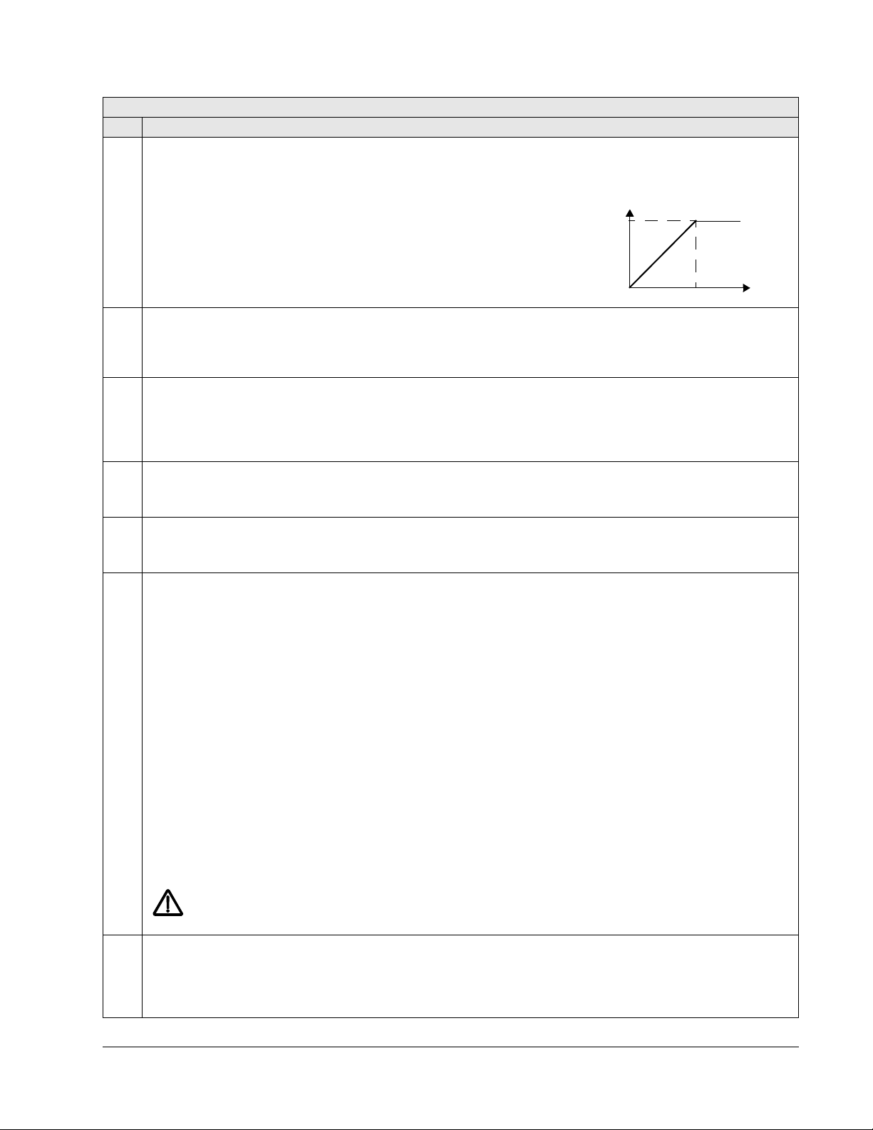
ACH550-UH User’s Manual 1-81
Output voltage
Output
P 9907
frequency
P 9905
Group 99: Start-up Data
Code Description Range Resolution Default S
9905 MOTOR NOM VOLT 115…345 V (200 V, US) 1 V 230 V (US)
230…690 V (400 V, US) 1 V 460 V (US)
288…862 V (600 V, US) 1 V 575 V (US)
Defines the nominal motor voltage.
• Must equal the value on the motor rating plate.
• The ACH550 cannot supply the motor with a voltage greater than the input
power (mains) voltage.
9906 MOTOR NOM CURR 0.15 · I
… 1.5 · I
2n
2n
0.1 A 1.0 · I
2n
Defines the nominal motor current.
• Must equal the value on the motor rating plate.
• Range allowed: 0.15…1.5 · I
(where I2n is drive current).
2n
9907 MOTOR NOM FREQ 10.0…500.0 Hz 0.1 Hz 60.0 Hz (US)
Defines the nominal motor frequency.
• Range: 10…500 Hz (typically 50 or 60 Hz)
• Sets the frequency at which output voltage equals the
MOTOR NOM VOLT.
• Field weakening point = Nom Freq · Supply Volt / Mot Nom Volt
9908 MOTOR NOM SPEED 50…30000 rpm 1 rpm Size dependent
Defines the nominal motor speed.
• Must equal the value on the motor rating plate.
9909 MOTOR NOM POWER 0.15…1.5 · P
n
0.1 hp 1.0 · P
n
Defines the nominal motor power.
• Must equal the value on the motor rating plate.
9910 ID RUN 0, 1 1 0 (
OFF/IDMAGN)
This parameter controls a self-calibration process called the Motor ID Run. During this process, the drive operates
the motor (motor rotating) and makes measurements in order to identify motor characteristics and create a model
used for internal calculations. An ID Run is especially effective when:
• vector control mode is used [parameter 9904 = 1 (
VECTOR:SPEED) or 2 (VECTOR:TORQ)], and/or
• operation point is near zero speed, and/or
• operation requires a torque range above the motor nominal torque, over a wide speed range, and without any
measured speed feedback (i.e. without a pulse encoder).
OFF/IDMAGN – The Motor ID Run process is not run. Identification magnetization is performed, depending on
0 =
parameter 9904 and 2101 settings. In identification magnetization, the motor model is calculated at first start by
magnetizing the motor for 10 to 15 s at zero speed (motor not rotating). The model is recalculated always at start
after motor parameter changes.
• Parameter 9904 = 1 (
• Parameter 9904 = 3 (
VECTOR:SPEED) or 2 (VECTOR:TORQ): Identification magnetization is performed.
SCALAR:FREQ) and parameter 2101 = 3 (SCALAR FLYST) or 5 (FLY + BOOST): Identification
magnetization is performed.
• Parameter 9904 = 3 (
BOOST): Identification magnetization is not performed.
1 =
ON – Enables the Motor ID Run, during which the motor is rotating, at the next start command. After run
SCALAR:FREQ) and parameter 2101 has other value than 3 (SCALAR FLYST) or 5 (FLY +
completion, this value automatically changes to 0.
Note: The motor must be de-coupled from the driven equipment.
Note: If motor parameters are changed after ID Run, repeat the ID Run.
WARNING! The motor will run at up to approximately 50…80% of the nominal speed during the ID Run.
The motor will rotate in the forward direction.
Ensure that it is safe to run the motor before performing the ID Run!
9915 MOTOR COSPHI 0.01…0.97 0.01 0 (
IDENTIFIED)
Defines the nominal motor cos phi (power factor). The parameter improves performance especially with high
efficiency motors.
IDENTIFIED – Drive identifies the cos phi automatically by estimation.
0 =
0.01…0.97 – Value entered used as the cos phi.
Parameters
Page 82

1-82 ACH550-UH User’s Manual
Group 01: OPERATING DATA
This group contains drive operating data, including actual signals. The drive sets the
values for actual signals, based on measurements or calculations. You cannot set
these values.
Group 01: Operating Data
Code Description Range Resolution Default S
0101 SPEED & DIR -30000…30000 rpm 1 rpm -
The calculated signed speed of the motor (rpm). The absolute value of 0101
SPEED.
0102
• The value of 0101
• The value of 0101
SPEED & DIR is positive if the motor runs in the forward direction.
SPEED & DIR is negative if the motor runs in the reverse direction.
0102 SPEED 0…30000 rpm 1 rpm -
The calculated speed of the motor (rpm).
0103 OUTPUT FREQ 0.0…500.0 Hz 0.1 Hz -
The frequency (Hz) applied to the motor.
0104 CURRENT 0.0…1.5 · I
2n
0.1 A -
The motor current, as measured by the ACH550.
0105 TORQUE -200.0…200.0% 0.1% -
Output torque. Calculated value of torque on motor shaft in % of motor nominal torque.
0106 POWER -1.5…1.5 · P
n
0.1 kW -
The measured motor power in kW.
0107 DC BUS VOLTAGE 0…2.5 · V
dN
1V -
The DC bus voltage in V DC, as measured by the ACH550.
0109 OUTPUT VOLTAGE 0…2.0 · V
dN
1V -
The voltage applied to the motor.
0110 DRIVE TEMP 0.0…150.0 °C 0.1 °C -
The temperature of the drive power transistors in degrees Celsius.
0111 EXTERNAL REF 1 0.0…500.0 Hz / 0.1 Hz / 1 rpm -
0…30000 rpm
External reference,
REF1, in rpm or Hz – units determined by parameter 9904.
0112 EXTERNAL REF 2 0.0…100.0% 0.1% -
(0.0…600.0% for torque)
External reference,
REF2, in %.
0113 CTRL LOCATION 0…2 1 -
Active control location. Alternatives are:
LOCAL
0 =
1 = EXT1
EXT2
2 =
0114 RUN TIME (R) 0…9999 h 1 h -
The drive’s accumulated running time in hours (h).
• Can be reset by pressing UP and DOWN keys simultaneously when the control panel is in the Parameters mode.
0115 KWH COUNTER (R) 0…65535 kWh 1 kWh -
The drive’s accumulated power consumption in kilowatt hours.
• The counter value is accumulated till it reaches 65535 after which the counter rolls over and starts again from 0.
• Can be reset by pressing UP and DOWN keys simultaneously when the control panel is in the Parameters mode.
SPEED & DIR is the same as the value of
Parameters
Page 83
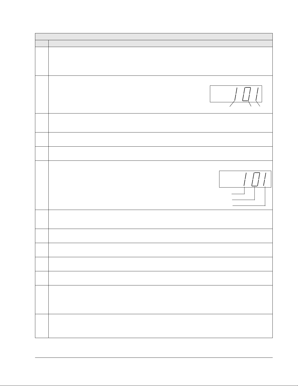
ACH550-UH User’s Manual 1-83
DI 1
DI 2 DI 3
RELAY 1 STATUS
RELAY 2 STATUS
RELAY
3 STATUS
Group 01: Operating Data
Code Description Range Resolution Default S
0116 APPL BLK OUTPUT 0.0…100.0% 0.1% -
(0.0…600.0% for torque)
Application block output signal. Value is from either:
• PFA control, if PFA Control is active, or
• Parameter 0112
0118 DI 1-3 STATUS 000…111 (0…7 decimal) 1 -
Status of the three digital inputs.
• Status is displayed as a binary number.
• 1 indicates that the input is activated.
• 0 indicates that the input is deactivated.
0119 DI 4-6 STATUS 000…111 (0…7 decimal) 1 -
Status of the three digital inputs.
• See parameter 0118
0120 AI 1 0.0…100.0% 0.1% -
The relative value of analog input 1 in %.
0121 AI 2 0.0…100.0% 0.1% -
The relative value of analog input 2 in %.
0122 RO 1-3 STATUS 000…111 (0…7 decimal) 1 -
Status of the three relay outputs.
• 1 indicates that the relay is energized.
• 0 indicates that the relay is de-energized.
EXTERNAL REF 2.
DI 1-3 STATUS.
0123 RO 4-6 STATUS 000…111 (0…7 decimal) 1 -
Status of the three relay outputs. Available if OREL-01 Relay Output Extension Module is installed.
• See parameter 0122.
0124 AO 1 0.0…20.0 mA 0.1 mA -
The analog output 1 value in milliamperes.
0125 AO 2 0.0…20.0 mA 0.1 mA -
The analog output 2 value in milliamperes.
0126 PID 1 OUTPUT -1000.0…1000.0% 0.1% -
The PID controller 1 output value in %.
0127 PID 2 OUTPUT -100.0…100.0% 0.1% -
The PID controller 2 output value in %.
0128 PID 1 SETPNT Unit and scale defined - -
by par. 4006/4106 and
4007/4107
PID 1 controller setpoint signal.
The
• Units and scale defined by PID parameters.
0129 PID 2 SETPNT Unit and scale defined - -
by par. 4206 and 4207
PID 2 controller setpoint signal.
The
• Units and scale defined by PID parameters.
Parameters
Page 84

1-84 ACH550-UH User’s Manual
Group 01: Operating Data
Code Description Range Resolution Default S
0130 PID 1 FBK Unit and scale defined - -
by par. 4006/4106 and
4007/4107
PID 1 controller feedback signal.
The
• Units and scale defined by PID parameters.
0131 PID 2 FBK Unit and scale defined - -
PID 2 controller feedback signal.
The
• Units and scale defined by PID parameters.
0132 PID 1 DEVIATION Unit and scale defined - -
The difference between the
PID 1 controller reference value and actual value.
• Units and scale defined by PID parameters.
0133 PID 2 DEVIATION Unit and scale defined - -
The difference between the
PID 2 controller reference value and actual value.
• Units and scale defined by PID parameters.
0134 COMM RO WORD 0…65535 1 -
Free data location that can be written from serial link.
• Used for relay output control.
• See parameter 1401.
0135 COMM VALUE 1 -32768…+32767 1 -
Free data location that can be written from serial link.
0136 COMM VALUE 2 -32768…+32767 1 -
Free data location that can be written from serial link.
0137 PROCESS VAR 1 - 1 -
Process variable 1
• Defined by parameters in Group 34: PANEL DISPLAY.
0138 PROCESS VAR 2 - 1 -
Process variable 2
• Defined by parameters in Group 34: PANEL DISPLAY.
0139 PROCESS VAR 3 - 1 -
Process variable 3
• Defined by parameters in Group 34: PANEL DISPLAY.
0140 RUN TIME 0.00…499.99 kh 0.01 kh -
The drive’s accumulated running time in thousands of hours (kh).
• Cannot be reset.
0141 MWH COUNTER 0…65535 MWh 1 MWh -
The drive’s accumulated power consumption in megawatt hours.
• The counter value is accumulated till it reaches 65535 after which the counter rolls over and starts again from 0.
• Cannot be reset.
0142 REVOLUTION CNTR 0…65535 Mrev 1 Mrev -
The motor’s accumulated revolutions in millions of revolutions.
• Can be reset by pressing UP and DOWN keys simultaneously when the control panel is in the Parameters mode.
0143 DRIVE ON TIME HI 0…65535 days 1 day -
The drive’s accumulated power-on time in days.
• Cannot be reset.
by par. 4206 and 4207
by par. 4006/4106 and
4007/4107
by par. 4206 and 4207
Parameters
Page 85

ACH550-UH User’s Manual 1-85
Group 01: Operating Data
Code Description Range Resolution Default S
0144 DRIVE ON TIME LO 00:00:00…23:59:58 1 = 2 s -
The drive’s accumulated power-on time in 2 second ticks (30 ticks = 60 seconds).
• Shown in format hh.mm.ss.
• Cannot be reset.
0145 MOTOR TEMP Par. 3501 = 1…3: 1 -
Motor temperature in degrees Celsius / PTC resistance in ohms.
• Applies only if motor temperature sensor is set up.
• See parameter 3501.
0150 CB TEMP -20.0…150.0 °C 1.0 °C -
Temperature of the drive control board in degrees Celsius.
Note: Some drives have a control board (OMIO) that does not support this feature. These drives always show the
constant value of 25.0 °C.
0153 MOT THERM STRESS 0.0…100.0% 0.1% -
Estimated rise of the motor temperature. Value equals to the estimated motor thermal stress as a percentage of the
motor temperature trip level.
0158 PID COMM VALUE 1 -32768…+32767 1 -
Data received from fieldbus for PID control (PID1 and PID2).
0159 PID COMM VALUE 2 -32768…+32767 1 -
Data received from fieldbus for PID control (PID1 and PID2).
0174 SAVED KWH 0.0…999.9 kWh 0.1 kWh -
Energy saved in kWh compared to the energy used when the pump is connected directly to the supply. See the note
on page 1-163.
• The counter value is accumulated till it reaches 999.9 after which the counter rolls over and starts again from 0.0.
• Can be reset with parameter 4509
•See Group 45: ENERGY SAVING.
0175 SAVED MWH 0…65535 MWh 1 MWh -
Energy saved in MWh compared to the energy used when the pump is connected directly to the supply. See the note
on page 1-163.
• The counter value is accumulated till it reaches 65535 after which the counter rolls over and starts again from 0.
• Can be reset with parameter 4509
•See Group 45: ENERGY SAVING.
0176 SAVED AMOUNT 1 0.0…999.9 0.1 -
Energy saved in local currency (remainder when the total saved energy is divided by 1000). See the note on
page 1-163.
• To find out the total saved energy in currency units, add the value of parameter 0177 multiplied by 1000 to the
value of parameter 0176.
Example:
SAVED AMOUNT 1 = 123.4
0176
0177
SAVED AMOUNT 2 = 5
Total saved energy = 5 · 1000 + 123.4 = 5123.4 currency units.
• The counter value is accumulated till it reaches 999.9 (the counter does not roll over).
• Can be reset with parameter 4509
• Local energy price is set with parameter 4502
•See Group 45: ENERGY SAVING.
-10…200 °C
Par. 3501 = 4: 0…5000 ohm
Par. 3501 = 5…6: 0…1
ENERGY RESET (resets all energy calculators at the same time).
ENERGY RESET (resets all energy calculators at the same time).
ENERGY RESET (resets all energy calculators at the same time).
ENERGY PRICE.
Parameters
Page 86

1-86 ACH550-UH User’s Manual
Group 01: Operating Data
Code Description Range Resolution Default S
0177 SAVED AMOUNT 2 0…65535 1 -
Energy saved in local currency in thousand currency units. Eg value 5 means 5000 currency units. See the note on
page 1-163.
• The counter value is accumulated till it reaches 65535 (the counter does not roll over).
• See parameter 0176
0178 SAVED CO2 0.0…6553.5 tn 0.1 tn -
Reduction of carbon dioxide emissions in tons. See the note on page 1-163.
• The counter value is accumulated till it reaches 6553.5 (the counter does not roll over).
• Can be reset with parameter 4509
• CO2 conversion factor is set with parameter 4507
•See Group 45: ENERGY SAVING.
SAVED AMOUNT 1.
ENERGY RESET (resets all energy calculators at the same time).
CO2 CONV FACTOR.
Parameters
Page 87

ACH550-UH User’s Manual 1-87
Bit # 0301, FB CMD WORD 1 0302, FB CMD WORD 2
0 STOP FBLOCAL_CTL
1 START FBLOCAL_REF
2 REVERSE START_DISABLE1
3 LOCAL START_DISABLE2
4 RESET Reserved
5 EXT2 Reserved
6 RUN_DISABLE Reserved
7 STPMODE_R Reserved
8 STPMODE_EM Reserved
9 STPMODE_C Reserved
10 RAMP_2 Reserved
11 RAMP_OUT_0 REF_CONST
12 RAMP_HOLD REF_AVE
13 RAMP_IN_0 LINK_ON
14 RREQ_LOCALLOC REQ_STARTINH
15 TORQLIM2 OFF_INTERLOCK
Group 03: ACTUAL SIGNALS
This group monitors fieldbus communications.
Group 03: Actual Signals
Code Description Range Resolution Default S
0301 FB CMD WORD 1 - 1 -
Read-only copy of the Fieldbus Command Word 1.
• The fieldbus command is the principal means for controlling the drive from a fieldbus controller. The command
consists of two Command Words. Bit-coded instructions in the Command Words switch the drive between states.
• To control the drive, using the Command Words, an external location (
COMM. (See parameters 1001 and 1002.)
The control panel displays the word in hex. For example, all zeros and a 1 in Bit 0 displays as 0001. All zeros and a
1 in Bit 15 displays as 8000.
EXT1 or EXT2) must be active and set to
0302 FB CMD WORD 2 - 1 -
Read-only copy of the Fieldbus Command Word 2.
• See parameter 0301.
Parameters
Page 88

1-88 ACH550-UH User’s Manual
Bit # 0303, FB STS WORD 1 0304, FB STS WORD 2
0 READY ALARM
1 ENABLED NOTICE
2 STARTED DIRLOCK
3 RUNNING LOCALLOCK
4 ZERO_SPEED CTL_MODE
5 ACCELERATE Reserved
6 DECELERATE Reserved
7 AT_SETPOINT CPY_CTL
8 LIMIT CPY_REF1
9 SUPERVISION CPY_REF2
10 REV_REF REQ_CTL
11 REV_ACT REQ_REF1
12 PANEL_LOCAL REQ_REF2
13 FIELDBUS_LOCAL REQ_REF2EXT
14 EXT2_ACT ACK_STARTINH
15 FAULT ACK_OFF_ILCK
Group 03: Actual Signals
Code Description Range Resolution Default S
0303 FB STS WORD 1 - 1 -
Read-only copy of the Status Word 1.
• The drive sends status information to the fieldbus controller. The status consists of two Status Words.
• The control panel displays the word in hex. For example, all zeros and a 1 in Bit 0 displays as 0001. All zeros and
a 1 in Bit 15 displays as 8000.
0304 FB STS WORD 2 - 1 -
Read-only copy of the Status Word 2.
• See parameter 0303.
Parameters
Page 89

ACH550-UH User’s Manual 1-89
Bit # 0305, FAULT WORD 1 0306, FAULT WORD 2 0307, FAULT WORD 3
0 OVERCURRENT Obsolete EFB 1
1 DC OVERVOLT THERM FAIL EFB 2
2 DEV OVERTEMP OPEX LINK EFB 3
3 SHORT CIRC OPEX PWR INCOMPATIBLE SW
4 Reserved CURR MEAS
USER LOAD CURVE
5 DC UNDERVOLT SUPPLY PHASE Reserved
6 AI1 LOSS ENCODER ERR Reserved
7 AI2 LOSS OVERSPEED Reserved
8 MOT OVERTEMP Reserved Reserved
9 PANEL LOSS DRIVE ID Reserved
10 ID RUN FAIL CONFIG FILE System error
11 MOTOR STALL SERIAL 1 ERR System error
12 CB OVERTEMP EFB CON FILE System error
13 EXT FAULT 1 FORCE TRIP System error
14 EXT FAULT 2 MOTOR PHASE System error
15 EARTH FAULT OUTP WIRING Param. setting fault
Group 03: Actual Signals
Code Description Range Resolution Default S
0305 FAULT WORD 1 - 1 -
Read-only copy of the Fault Word 1.
• When a fault is active, the corresponding bit for the active fault is set in the Fault Words.
• Each fault has a dedicated bit allocated within Fault Words.
• See section Fault listing on page 1-282 for a description of the faults.
• The control panel displays the word in hex. For example, all zeros and a 1 in Bit 0 displays as 0001. All zeros and
a 1 in Bit 15 displays as 8000.
0306 FAULT WORD 2 - 1 -
Read-only copy of the Fault Word 2.
• See parameter 0305.
0307 FAULT WORD 3 - 1 -
Read-only copy of the Fault Word 3.
• See parameter 0305.
Parameters
Page 90

1-90 ACH550-UH User’s Manual
Bit # 0308, ALARM WORD 1 0309, ALARM WORD 2
0 OVERCURRENT Reserved
1 OVERVOLTAGE PID SLEEP
2 UNDERVOLTAGE ID RUN
3 DIR LOCK Reserved
4 IO COMM START ENABLE 1 MISSING
5 AI1 LOSS START ENABLE 2 MISSING
6 AI2 LOSS EMERGENCY STOP
7 PANEL LOSS ENCODER ERROR
8 DEVICE OVERTEMP FIRST START
9MOTOR TEMP Reserved
10 Reserved USER LOAD CURVE
11 MOTOR STALL START DELAY
12 AUTORESET Reserved
13 AUTOCHANGE Reserved
14 PFA I LOCK Reserved
15 Reserved Reserved
Group 03: Actual Signals
Code Description Range Resolution Default S
0308 ALARM WORD 1 - 1 -
• When an alarm is active, the corresponding bit for the active alarm is set in the Alarm Words.
• Each alarm has a dedicated bit allocated within Alarm Words.
• Bits remain set until the whole alarm word is reset. (Reset by writing zero to the word.)
• The control panel displays the word in hex. For example, all zeros and a 1 in Bit 0 displays as 0001. All zeros and
a 1 in Bit 15 displays as 8000.
0309 ALARM WORD 2 - 1 -
• See parameter 0308.
Parameters
Page 91

ACH550-UH User’s Manual 1-91
Group 04: FAULT HISTORY
This group stores a recent history of the faults reported by the drive.
Group 04: Fault History
Code Description Range Resolution Default S
0401 LAST FAULT Fault codes 1 0
(panel displays as text)
0 – Clear the fault history (on panel = NO RECORD).
n – Fault code of the last recorded fault. The fault code is displayed as a name. See section Fault listing on
page 1-282 for the fault codes and names. The fault name shown for this parameter may be shorter than the
corresponding name in the fault listing, which shows the names as they are shown in the fault display.
0402 FAULT TIME 1 Date dd.mm.yy / 1 day 0
power-on time in days
The day on which the last fault occurred. Either as:
• A date – if real time clock is operating.
• The number of days after power on – if real time clock is not used, or was not set.
0403 FAULT TIME 2 Time hh:mm:ss 2 s 0
The time at which the last fault occurred. Either as:
• Real time, in format hh:mm:ss – if real time clock is operating.
• The time since power on (minus the whole days reported in 0402), in format hh:mm:ss – if real time clock is not
used, or was not set.
• Format on the Basic Control Panel: The time since power on in 2-second ticks (minus the whole days reported in
0402). 30 ticks = 60 seconds. E.g. Value 514 equals 17 minutes and 8 seconds (= 514/30).
0404 SPEED AT FLT -32768…+32767 1 rpm 0
The motor speed (rpm) at the time the last fault occurred.
0405 FREQ AT FLT -3276.8…+3276.7 0.1 Hz 0
The frequency (Hz) at the time the last fault occurred.
0406 VOLTAGE AT FLT 0.0…6553.5 0.1 V 0
The DC bus voltage (V) at the time the last fault occurred.
0407 CURRENT AT FLT 0.0…6553.5 0.1 A 0
The motor current (A) at the time the last fault occurred.
0408 TORQUE AT FLT -3276.8…+3276.7 0.1% 0
The motor torque (%) at the time the last fault occurred.
0409 STATUS AT FLT 0000…FFFF hex 1 0
The drive status (hex code word) at the time the last fault occurred.
0410 DI 1-3 AT FLT 000…111 1 0
(0…7 decimal)
The status of digital inputs 1…3 at the time the last fault occurred.
0411 DI 4-6 AT FLT 000…111 1 0
(0…7 decimal)
The status of digital inputs 4…6 at the time the last fault occurred.
0412 PREVIOUS FAULT 1 As par. 0401 1 0
Fault code of the second last fault. Read-only.
0413 PREVIOUS FAULT 2 As par. 0401 1 0
Fault code of the third last fault. Read-only.
Parameters
Page 92

1-92 ACH550-UH User’s Manual
Group 10: START/STOP/DIR
This group:
• defines external sources (
EXT1 and EXT2) for commands that enable start, stop
and direction changes
• locks direction or enables direction control.
To select between the two external locations use the next group (parameter 1102).
Group 10: Start/Stop/Dir
Code Description Range Resolution Default S
1001 EXT1 COMMANDS 0…14 1 1 (
Defines external control location 1 (
NOT SEL – No external start, stop and direction command source.
0 =
DI1 – Two-wire Start/Stop.
1 =
EXT1) – the configuration of start, stop and direction commands.
• Start/Stop is through digital input DI1 (DI1 activated = Start; DI1 de-activated = Stop).
• Parameter 1003 defines the direction. Selecting 1003 = 3 (
DI1,2 – Two-wire Start/Stop, Direction.
2 =
• Start/Stop is through digital input
• Direction control [requires parameter 1003 = 3 (
DI2 activated = Reverse; de-activated = Forward).
(
DI1 (DI1 activated = Start; DI1 de-activated = Stop).
REQUEST)] is through digital input DI2
REQUEST) is the same as 1003 = 1 (FORWARD).
3 = DI1P,2P – Three-wire Start/Stop.
• Start/Stop commands are through momentary push-buttons (the
• Start is through a normally open push-button connected to digital input
P stands for “pulse”).
DI1. In order to start the drive, the digital
input DI2 must be activated prior to the pulse in DI1.
• Connect multiple Start push-buttons in parallel.
• Stop is through a normally closed push-button connected to digital input
DI2.
• Connect multiple Stop push-buttons in series.
• Parameter 1003 defines the direction. Selecting 1003 = 3 (
DI1P,2P,3 – Three-wire Start/Stop, Direction.
4 =
REQUEST) is the same as 1003 = 1 (FORWARD).
• Start/Stop commands are through momentary push-buttons, as described for DI1P,2P.
• Direction control [requires parameter 1003 = 3 (
DI3 activated = Reverse; de-activated = Forward).
(
REQUEST)] is through digital input DI3
5 = DI1P,2P,3P – Start Forward, Start Reverse and Stop.
• Start and Direction commands are given simultaneously with two separate momentary push-buttons (the
stands for “pulse”).
• Start Forward command is through a normally open push-button connected to digital input
the drive, the digital input
DI3 must be activated prior to the pulse in DI1.
• Start Reverse command is through a normally open push-button connected to digital input
the drive, the digital input DI3 must be activated during the pulse in DI2.
• Connect multiple Start push-buttons in parallel.
• Stop is through a normally closed push-button connected to digital input
DI3.
• Connect multiple Stop push-buttons in series.
• Requires parameter 1003 = 3 (
DI6 – Two-wire Start/Stop.
6 =
REQUEST).
• Start/Stop is through digital input DI6 (DI6 activated = Start; DI6 de-activated = Stop).
• Parameter 1003 defines the direction. Selecting 1003 = 3 (
DI6,5 – Two-wire Start/Stop/Direction.
7 =
• Start/Stop is through digital input
• Direction control [requires parameter 1003 = 3 (
DI5 activated = Reverse; de-activated = Forward).
(
DI6 (DI6 activated = Start; DI6 de-activated = Stop).
REQUEST)] is through digital input DI5.
REQUEST) is the same as 1003 = 1 (FORWARD).
8 = KEYPAD – Control Panel.
• Start/Stop and Direction commands are through the control panel when
• Direction control requires parameter 1003 = 3 (
REQUEST).
EXT1 is active.
9 = DI1F,2R – Start/Stop/Direction commands through DI1 and DI2 combinations.
• Start forward =
• Start reverse =
• Stop = both
• Requires parameter 1003 = 3 (
DI1 activated and DI2 de-activated.
DI1 de-activated and DI2 activated.
DI1 and DI2 activated, or both de-activated.
REQUEST).
DI1)
P
DI1. In order to start
DI2. In order to start
Parameters
Page 93

ACH550-UH User’s Manual 1-93
Group 10: Start/Stop/Dir
Code Description Range Resolution Default S
10 = COMM – Assigns the fieldbus Command Word as the source for the start/stop and direction commands.
• Bits 0, 1, 2 of Command Word 1 (parameter 0301) activates the start/stop and direction commands.
• See Fieldbus user’s manual for detailed instructions.
TIMED FUNC 1. – Assigns Start/Stop control to Timed Function 1 (Timed Function activated = START; Timed
11 =
Function de-activated =
12…14 =
TIMED FUNC 2…4 – Assigns Start/Stop control to Timed Function 2…4. See TIMED FUNC 1 above.
1002 EXT2 COMMANDS 0…14 1 1 (
Defines external control location 2 (
• See parameter 1001
1003 DIRECTION 1…3 1 1 (FORWARD)
Defines the control of motor rotation direction.
FORWARD – Rotation is fixed in the forward direction.
1 =
2 = REVERSE – Rotation is fixed in the reverse direction.
REQUEST – Rotation direction can be changed on command.
3 =
STOP). See Group 36: TIMED FUNCTIONS.
DI1)
EXT2) – the configuration of start, stop and direction commands.
EXT1 COMMANDS above.
Parameters
Page 94

1-94 ACH550-UH User’s Manual
REF1
Panel REF1
P1101
REF1
REF2
P1107
P1108
P1106
0…17
Panel REF 2
PID 1 OUT
REF 2
P1102
EXT 1
EXT 2
P1104
P1105
P1103
Panel REF 1
DI
AI
EXT2
P1107
P1108
P1106
0…17
19
19
G12
Const
Speed
P1106
Panel Ref 2
DI
AI
EXT2
PANEL
Hand/Auto
Selection
HAND
AUTO
Group 11: REFERENCE SELECT
This group defines:
• how the drive selects between command sources
• characteristics and sources for
REF1 and REF2.
Group 11: Reference Select
Code Description Range Resolution Default S
1101 KEYPAD REF SEL 1, 2 1 1 [REF1(Hz/rpm)]
Selects the reference controlled in local control mode.
REF1(Hz/rpm) – Reference type depends on parameter 9904 MOTOR CTRL MODE.
1 =
• Speed reference (rpm) if 9904 = 1 (VECTOR:SPEED) or 2 (VECTOR:TORQ).
• Frequency reference (Hz) if 9904 = 3 (
REF2(%)
2 =
SCALAR:FREQ).
1102 EXT1/EXT2 SEL -6…12 1 0 (EXT1)
Defines the source for selecting between the two external control locations
EXT1 or EXT2. Thus, defines the source
for Start/Stop/Direction commands and reference signals.
EXT1 – Selects external control location 1 (EXT1).
0 =
• See parameter 1001
• See parameter 1103
1 =
DI1 – Assigns control to EXT1 or EXT2 based on the state of DI1 (DI1 activated = EXT2; DI1 de-activated = EXT1).
DI2…DI6 – Assigns control to EXT1 or EXT2 based on the state of the selected digital input. See DI1 above.
2…6 =
EXT2 – Selects external control location 2 (EXT2).
7 =
EXT1 COMMANDS for EXT1’s Start/Stop/Dir definitions.
REF1 SELECT for EXT1’s reference definitions.
• See parameter 1002 EXT2 COMMANDS for EXT2’s Start/Stop/Dir definitions.
• See parameter 1106
COMM – Assigns control of the drive via external control location EXT1 or EXT2 based on the fieldbus control word.
8 =
REF2 SELECT for EXT2’s reference definitions.
• Bit 5 of the Command Word 1 (parameter 0301) defines the active external control location (EXT1 or EXT2).
• See Fieldbus user’s manual for detailed instructions.
9 =
activated = EXT2; Timed Function de-activated = EXT1). See Group 36: TIMED FUNCTIONS.
10…12 =
FUNC 1 above.
-1 = DI1(INV) – Assigns control to EXT1 or EXT2 based on the state of DI1 (DI1 activated = EXT1; DI1 de-activated =
EXT2).
-2…-6 =
DI1(INV) above.
Parameters
TIMED FUNC 1 – Assigns control to EXT1 or EXT2 based on the state of the Timed Function (Timed Function
TIMED FUNC 2…4 – Assigns control to EXT1 or EXT2 based on the state of the Timed Function. See TIMED
DI2(INV)…DI6(INV) – Assigns control to EXT1 or EXT2 based on the state of the selected digital input. See
Page 95

+2%-2%
10 V /
Hysteresis 4% of full scale
EXT REF 1 MIN
- EXT REF 1 MIN
- EXT REF 1 MAX
EXT
REF 1 MIN
EXT
REF 1 MAX
- EXT REF 1 MIN
2V / 4mA
0V / 0mA
20 mA
ACH550-UH User’s Manual 1-95
Group 11: Reference Select
Code Description Range Resolution Default S
1103 REF1 SELECT 0…17, 20…21 1 1 (AI1)
Selects the signal source for external reference
0 = KEYPAD – Defines the control panel as the reference
source.
AI1 – Defines analog input 1 (AI1) as the reference
1 =
source.
AI2 – Defines analog input 2 (AI2) as the reference
2 =
source.
AI1/JOYST – Defines analog input 1 (AI1), configured for
3 =
joystick operation, as the reference source.
• The minimum input signal runs the drive at the maximum
reference in the reverse direction. Define the minimum
using parameter 1104.
• The maximum input signal runs the drive at maximum
reference in the forward direction. Define the maximum
using parameter 1105.
• Requires parameter 1003 = 3 (
REQUEST).
WARNING! Because the low end of the reference
range commands full reverse operation, do not use
0 V as the lower end of the reference range. Doing so means that if the control signal is lost (which is a 0 V
input) the result is full reverse operation. Instead, use the following set-up so that loss of the analog input
triggers a fault, stopping the drive:
• Set parameter 1301
• Set parameter 3021
MINIMUM AI1 (1304 MINIMUM AI2) at 20% (2 V or 4 mA).
AI1 FAULT LIMIT to a value 5% or higher.
• Set parameter 3001 AI<MIN FUNCTION to 1 (FAULT).
AI2/JOYST – Defines analog input 2 (AI2), configured for joystick operation, as the reference source.
4 =
• See above (
AI1/JOYST) description.
5 = DI3U,4D(R) – Defines digital inputs as the speed reference source (motor potentiometer control).
• Digital input
• Digital input
DI3 increases the speed (the U stands for “up”).
DI4 decreases the speed (the D stands for “down”).
• A Stop command resets the reference to zero (the R stands for “reset”).
• Parameter 2205
DI3U,4D – Same as above (DI3U,4D(R)), except:
6 =
ACCELER TIME 2 controls the reference signal’s rate of change.
• A Stop command does not reset the reference to zero. The reference is stored.
• When the drive restarts, the motor ramps up (at the selected acceleration rate) to the stored reference.
DI5U,6D – Same as above (DI3U,4D), except that DI5 and DI6 are the digital inputs used.
7 =
8 = COMM – Defines the fieldbus as the reference source.
COMM+AI1 – Defines a fieldbus and analog input 1 (AI1) combination as the reference source. See Analog input
9 =
reference correction below.
COMM*AI1 – Defines a fieldbus and analog input 1 (AI1) combination as the reference source. See Analog input
10 =
reference correction below.
DI3U,4D(RNC) – Same as DI3U,4D(R) above, except that:
11 =
• Changing the control source (
DI3U,4D(NC) – Same as DI3U,4D above, except that:
12 =
• Changing the control source (
EXT1 to EXT2, EXT2 to EXT1, LOC to REM) does not copy the reference.
EXT1 to EXT2, EXT2 to EXT1, LOC to REM) does not copy the reference.
13 = DI5U,6D(NC) – Same as DI5U,6D above, except that:
• Changing the control source (
AI1+AI2 – Defines an analog input 1 (AI1) and analog input 2 (AI2) combination as the reference source. See
14 =
EXT1 to EXT2, EXT2 to EXT1, LOC to REM) does not copy the reference.
Analog input reference correction below.
AI1*AI2 – Defines an analog input 1 (AI1) and analog input 2 (AI2) combination as the reference source. See
15 =
Analog input reference correction below.
AI1-AI2 – Defines an analog input 1 (AI1) and analog input 2 (AI2) combination as the reference source. See
16 =
Analog input reference correction below.
AI1/AI2 – Defines an analog input 1 (AI1) and analog input 2 (AI2) combination as the reference source. See
17 =
Analog input reference correction below.
KEYPAD(RNC) – Defines the control panel as the reference source.
20 =
• A Stop command resets the reference to zero (the
• Changing the control source (
KEYPAD(NC) – Defines the control panel as the reference source.
21 =
• A Stop command does not reset the reference to zero. The reference is stored.
• Changing the control source (
EXT1 to EXT2, EXT2 to EXT1) does not copy the reference.
EXT1 to EXT2, EXT2 to EXT1) does not copy the reference.
REF1.
R stands for reset.).
Parameters
Page 96
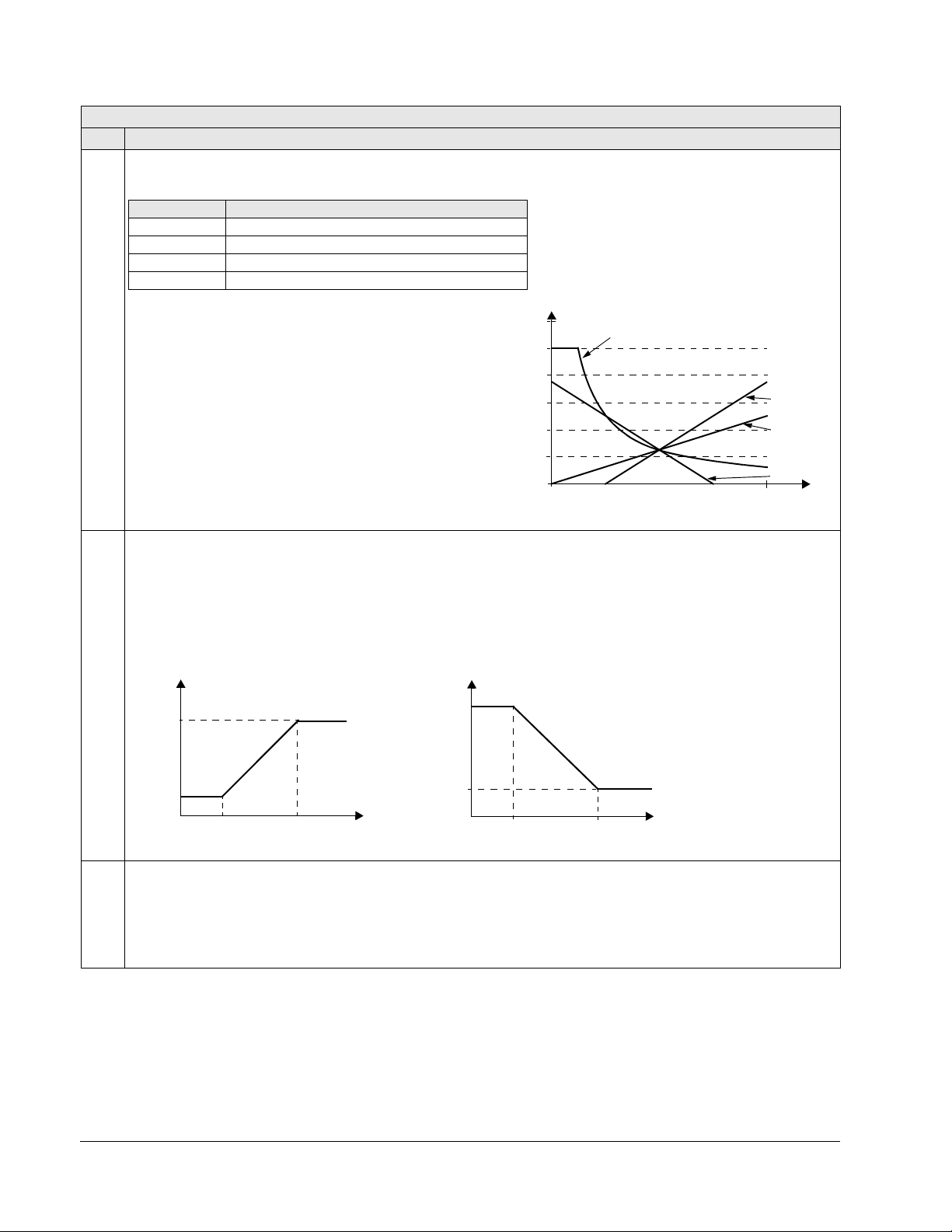
1-96 ACH550-UH User’s Manual
Value setting Calculation of the AI reference
C + B C value + (B value - 50% of reference value)
C * B C value · (B value / 50% of reference value)
C - B (C value + 50% of reference value) - B value
C / B (C value · 50% of reference value) / B value
120
100
80
60
40
20
0
0
100%
9, 14 (+)
16 (-)
10, 15 (*)
17 (/)
B
Ext ref
Analog
P 1105
P 1104
P 1301
P 1302
input signal
P 1301
P 1302
input signal
Analog
Ext ref
or 1304
or 1305
or 1304
or 1305
(
MAX)
(
MIN)
P 1105
P 1104
(
MAX)
(
MIN)
Group 11: Reference Select
Code Description Range Resolution Default S
Analog Input Reference Correction
Parameter values 9, 10 and 14…17 use the formula in the following table.
Where:
• C = Main reference value
COMM for values 9, 10 and
( =
= AI1 for values 14…17).
• B = Correcting reference
AI1 for values 9, 10 and
( =
= AI2 for values 14…17).
Example:
The figure shows the reference source curves for value
settings 9, 10 and 14…17, where:
•C = 25%.
• P 4012
• P 4013 SETPOINT MAX = 0.
• B varies along the horizontal axis.
SETPOINT MIN = 0.
1104 REF1 MIN 0.0…500.0 Hz / 0.1 Hz / 0.0 Hz /
0…30000 rpm 1 rpm 0 rpm
Sets the minimum for external reference 1.
• The minimum analog input signal (as a percent of the full signal in volts or amperes) corresponds to
Hz/rpm.
• Parameter 1301
MINIMUM AI1 or 1304 MINIMUM AI2 sets the minimum analog input signal.
• These parameters (reference and analog min. and max. settings) provide scale and offset adjustment for the
reference.
1105 REF1 MAX 0.0…500.0 Hz / 0.1 Hz / 60.0 Hz (US) /
0…30000 rpm 1 rpm 1800 rpm (US)
Sets the maximum for external reference 1.
• The maximum analog input signal (as a percent of full the signal in volts or amperes) corresponds to
Hz/rpm.
• Parameter 1302
MAXIMUM AI1 or 1305 MAXIMUM AI2 sets the maximum analog input signal.
REF1 MIN in
REF1 MAX in
Parameters
Page 97
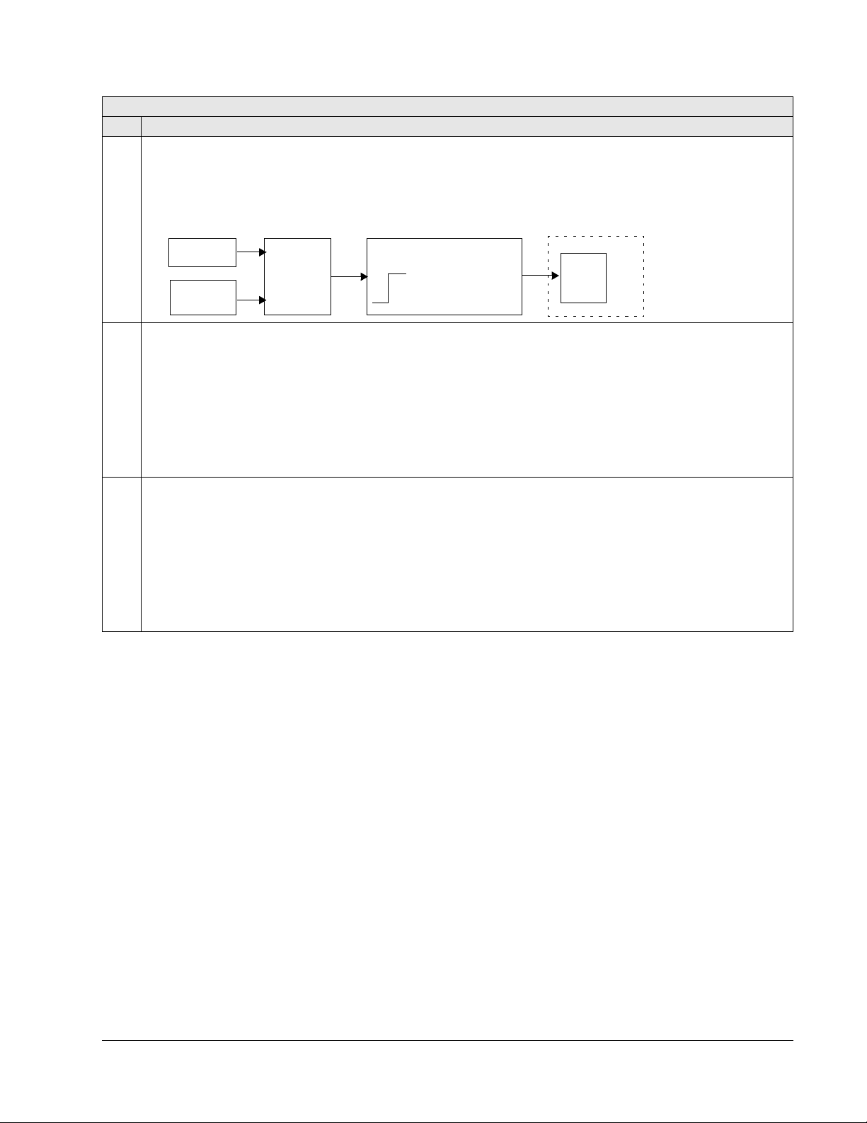
ACH550-UH User’s Manual 1-97
19=PID1 REF2
SELECT
LIMIT
MAX (1107, 1108)
MIN (1107, 1108)
PFA
If PFA is used
1…17
20…21
Group 11: Reference Select
Code Description Range Resolution Default S
1106 REF2 SELECT 0…17, 19…21 1 19 (PID1OUT)
Selects the signal source for external reference
0…17 – Same as for parameter 1103 REF1 SELECT.
PID1OUT – The reference is taken from the PID1 output. See Group 40: PROCESS PID SET 1 and Group 41:
19 =
PROCESS PID SET 2.
20…21 – Same as for parameter 1103
REF1 SELECT.
REF2.
1107 REF2 MIN 0.0…100.0% 0.1% 0.0%
(0.0…600.0% for toruqe)
Sets the minimum for external reference 2.
• The minimum analog input signal (in volts or amperes) corresponds to
• Parameter 1301
MINIMUM AI1 or 1304 MINIMUM AI2 sets the minimum analog input signal.
REF2 MIN in %.
• This parameter sets the minimum frequency reference.
• The value is a percentage of the:
– maximum frequency or speed
– maximum process reference
– nominal torque.
1108 REF2 MAX 0.0…100.0% 0.1% 100.0%
(0.0…600.0% for torqe)
Sets the maximum for external reference 2.
• The maximum analog input signal (in volts or amperes) corresponds to
• Parameter 1302
MAXIMUM AI1 or 1305 MAXIMUM AI2 sets the maximum analog input signal.
REF2 MAX in %.
• This parameter sets the maximum frequency reference.
• The value is a percentage of the:
– maximum frequency or speed
– maximum process reference
– nominal torque.
Parameters
Page 98

1-98 ACH550-UH User’s Manual
DI1 DI2 Function
0 0 No constant speed
1 0 Constant speed 1 (1202)
0 1 Constant speed 2 (1203)
1 1 Constant speed 3 (1204)
Group 12: CONSTANT SPEEDS
This group defines a set of constant speeds. In general:
• You can program up to 7 constant speeds, ranging from 0
0
…30000 rpm.
…500 Hz or
• Values must be positive (No negative speed values for constant speeds).
• Constant speed selections are ignored if:
– the torque control is active, or
– the process PID reference is followed, or
– the drive is in local control mode, or
– PFA (Pump-Fan Alternation) is active.
Note: Parameter 1208 CONST SPEED 7 acts also as a so-called fault speed which
may be activated if the control signal is lost. For example, see parameters 3001
AI<MIN FUNCTION, 3002 PANEL COMM ERR and 3018 COMM FAULT FUNC.
Group 12: Constant Speeds
Code Description Range Resolution Default S
1201 CONST SPEED SEL -14 …19 1 3 (
Defines the digital inputs used to select Constant Speeds. See general comments in introduction.
NOT SEL – Disables the constant speed function.
0 =
DI1 – Selects Constant Speed 1 with digital input DI1.
1 =
• Digital input activated = Constant Speed 1 activated.
DI2…DI6 – Selects Constant Speed 1 with digital input DI2…DI6. See above.
2…6 =
DI1,2 – Selects one of three Constant Speeds (1…3) using DI1 and DI2.
7 =
• Uses two digital inputs, as defined below (0 =
DI de-activated, 1 = DI activated):
DI3)
• Can be set up as a so-called fault speed, which is activated if the control signal is lost. Refer to parameter 3001
AI<MIN function and parameter 3002 PANEL COMM ERR.
DI2,3 – Selects one of three Constant Speeds (1…3) using DI2 and DI3.
8 =
• See above (
DI3,4 – Selects one of three Constant Speeds (1…3) using DI3 and DI4.
9 =
• See above (
DI4,5 – Selects one of three Constant Speeds (1…3) using DI4 and DI5.
10 =
DI1,2) for code.
DI1,2) for code.
• See above (DI1,2) for code.
DI5,6 – Selects one of three Constant Speeds (1…3) using DI5 and DI6.
11 =
• See above (DI1,2) for code.
Parameters
Page 99
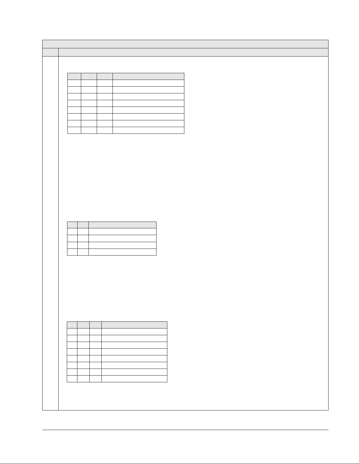
ACH550-UH User’s Manual 1-99
DI1 DI2 DI3 Function
0 0 0 No constant speed
1 0 0 Constant speed 1 (1202)
0 1 0 Constant speed 2 (1203)
1 1 0 Constant speed 3 (1204)
0 0 1 Constant speed 4 (1205)
1 0 1 Constant speed 5 (1206)
0 1 1 Constant speed 6 (1207)
1 1 1 Constant speed 7 (1208)
DI1 DI2 Function
1 1 No constant speed
0 1 Constant speed 1 (1202)
1 0 Constant speed 2 (1203)
0 0 Constant speed 3 (1204)
DI1 DI2 DI3 Function
1 1 1 No constant speed
0 1 1 Constant speed 1 (1202)
1 0 1 Constant speed 2 (1203)
0 0 1 Constant speed 3 (1204)
1 1 0 Constant speed 4 (1205)
0 1 0 Constant speed 5 (1206)
1 0 0 Constant speed 6 (1207)
0 0 0 Constant speed 7 (1208)
Group 12: Constant Speeds
Code Description Range Resolution Default S
12 = DI1,2,3 – Selects one of seven Constant Speeds (1…7) using DI1, DI2 and DI3.
• Uses three digital inputs, as defined below (0 = DI de-activated, 1 = DI activated):
DI3,4,5 – Selects one of seven Constant Speeds (1…7) using DI3, DI4 and DI5.
13 =
• See above (
14 = DI4,5,6 – Selects one of seven Constant Speeds (1…7) using DI4, DI5 and DI6.
• See above (
15…18 =
the state of the Timed Function (1…4) and constant speed mode. See parameter 1209 TIMED MODE SEL and Group
36: TIMED FUNCTIONS.
TIMED FUN1&2 – Selects a constant speed or the external reference, depending on the state of Timed Functions
19 =
1 & 2 and constant speed mode. See parameter 1209 TIMED MODE SEL and Group 36: TIMED FUNCTIONS.
DI1(INV) – Selects Constant Speed 1 with digital input DI1.
-1 =
• Inverse operation: Digital input de-activated = Constant Speed 1 activated.
-2…- 6 =
DI1,2(INV) – Selects one of three Constant Speeds (1…3) using DI1 and DI2.
-7 =
• Inverse operation uses two digital inputs, as defined below (0 =
DI1,2,3) for code.
DI1,2,3) for code.
TIMED FUNC 1…4 – Selects Constant Speed 1, Constant Speed 2 or the external reference, depending on
DI2(INV)…DI6(INV) – Selects Constant Speed 1 with digital input. See above.
DI de-activated, 1 = DI activated):
-8 =
DI2,3(INV) – Selects one of three Constant Speeds (1…3) using DI2 and DI3.
• See above (
DI1,2(INV)) for code.
-9 = DI3,4(INV) – Selects one of three Constant Speeds (1…3) using DI3 and DI4.
• See above (
DI4,5(INV) – Selects one of three Constant Speeds (1…3) using DI4 and DI5.
-10 =
DI1,2(INV)) for code.
• See above (DI1,2(INV)) for code.
DI5,6(INV) – Selects one of three Constant Speeds (1…3) using DI5 and DI6.
-11 =
• See above (
-12 =
DI1,2,3(INV) – Selects one of seven Constant Speeds (1…7) using DI1, DI2 and DI3.
DI1,2(INV)) for code.
• Inverse operation uses three digital inputs, as defined below (0 =
-13 =
DI3,4,5(INV) – Selects one of seven Constant Speeds (1…7) using DI3, DI4 and DI5.
• See above (
DI4,5,6(INV) – Selects one of seven Constant Speeds (1…7) using DI4, DI5 and DI6.
-14 =
• See above (
DI1,2,3(INV)) for code.
DI1,2,3(INV)) for code.
DI de-activated, 1 = DI activated):
Parameters
Page 100

1-100 ACH550-UH User’s Manual
Group 12: Constant Speeds
Code Description Range Resolution Default S
1202 CONST SPEED 1 0.0…500.0 Hz / 0.1 Hz / 6.0 Hz (US) /
0…30000 rpm 1 rpm 360 rpm (US)
Sets value for Constant Speed 1.
• The range and units depend on parameter 9904
• Range: 0…30000 rpm when 9904 = 1 (
• Range: 0…500 Hz when 9904 = 3 (
VECTOR:SPEED).
SCALAR:FREQ).
1203 CONST SPEED 2 0.0…500.0 Hz / 0.1 Hz / 12.0 Hz (US) /
0…30000 rpm 1 rpm 720 rpm (US)
Sets value for Constant Speed 2. See
CONST SPEED 1 above.
1204 CONST SPEED 3 0.0…500.0 Hz / 0.1 Hz / 18.0 Hz (US) /
0…30000 rpm 1 rpm 1080 rpm (US)
Sets value for Constant Speed 3. See
CONST SPEED 1 above.
1205 CONST SPEED 4 0.0…500.0 Hz / 0.1 Hz / 24.0 Hz (US) /
0…30000 rpm 1 rpm 1440 rpm (US)
Sets value for Constant Speed 4. See
CONST SPEED 1 above.
1206 CONST SPEED 5 0.0…500.0 Hz / 0.1 Hz / 30.0 Hz (US) /
0…30000 rpm 1 rpm 1800 rpm (US)
Sets value for Constant Speed 5. See
CONST SPEED 1 above.
1207 CONST SPEED 6 0.0…500.0 Hz / 0.1 Hz / 48.0 Hz (US) /
0…30000 rpm 1 rpm 2880 rpm (US)
Sets value for Constant Speed 6. See
CONST SPEED 1 above.
1208 CONST SPEED 7 0.0…500.0 Hz / 0.1 Hz / 60.0 Hz (US) /
0…30000 rpm 1 rpm 3600 rpm (US)
Sets value for Constant Speed 7. See
CONST SPEED 1 above.
MOTOR CTRL MODE.
Parameters
 Loading...