

Page 1
IEC/UL/CSA Technical data
!
R6
R4
8
Across the line
1
Contactors
Main pole - Utilization characteristics according to IEC
Contactor types
Standards
Rated operational voltage Ue max.
Rated frequency (without derating)
Conventional free-air thermal current Ith
acc. to IEC 60947-4-1, open contactors, θ ≤ 40 °C
With conductor cross-sectional area 35 mm² 35 mm² 50 mm²
AC-1 Utilization category
For air temperature close to contactor
Ie / Rated operational current AC-1
Ue max. ≤ 690 V, 50/60 Hz
With conductor cross-sectional area 25 mm² 35 mm² 50 mm²
Short-circuit protection device for contactors
without thermal overload relay - Motor protection excluded
Ue ≤ 500 V AC - gG type fuse
Rated short-time withstand current Icw
At 40 °C ambient temperature,
in free air from a cold state
Power dissipation per pole
Max. electrical switching frequency
(1) Unauthorized for TAE.. contactors
A/E/F45...A/E/F75, 4-pole
Utilization characteristics
AC operated
DC operated
AC / DC operated
θ ≤ 40 °C
θ ≤ 55 °C
θ ≤ 70 °C (1) 50 A 70 A 85 A
Ie / AC-1
A45 A50 A75
AE45 AE50 AE75
TAE45 TAE50 TAE75
AF45 AF50 AF75
IEC 60947-1 / 60947-4-1 and EN 60947-1 / 60947-4-1
1000 V (690 V for AF.. contactors)
50 / 60 Hz
100 A 100 A 125 A
70 A 100 A 125 A
60 A 85 A 105 A
80 A 100 A 160 A
1 s
1000 A
10 s
650 A
30 s
370 A
1 min
250 A
15 min
110 A 110 A 135 A
2.5 W 5 W 7 W
AC-1
600 cycles/h (300 for AF.., AE.., TAE..)
Main pole - Utilization characteristics according to UL / CSA
Contactor types
Standards
Max. operational voltage
UL / CSA general use rating
600 V AC 65 A 80 A 105 A
With conductor cross-sectional area AWG 6 AWG 4 AWG 2
Max. electrical switching frequency
For general use 600 cycles/h (300 for AF.., AE.. TAE..)
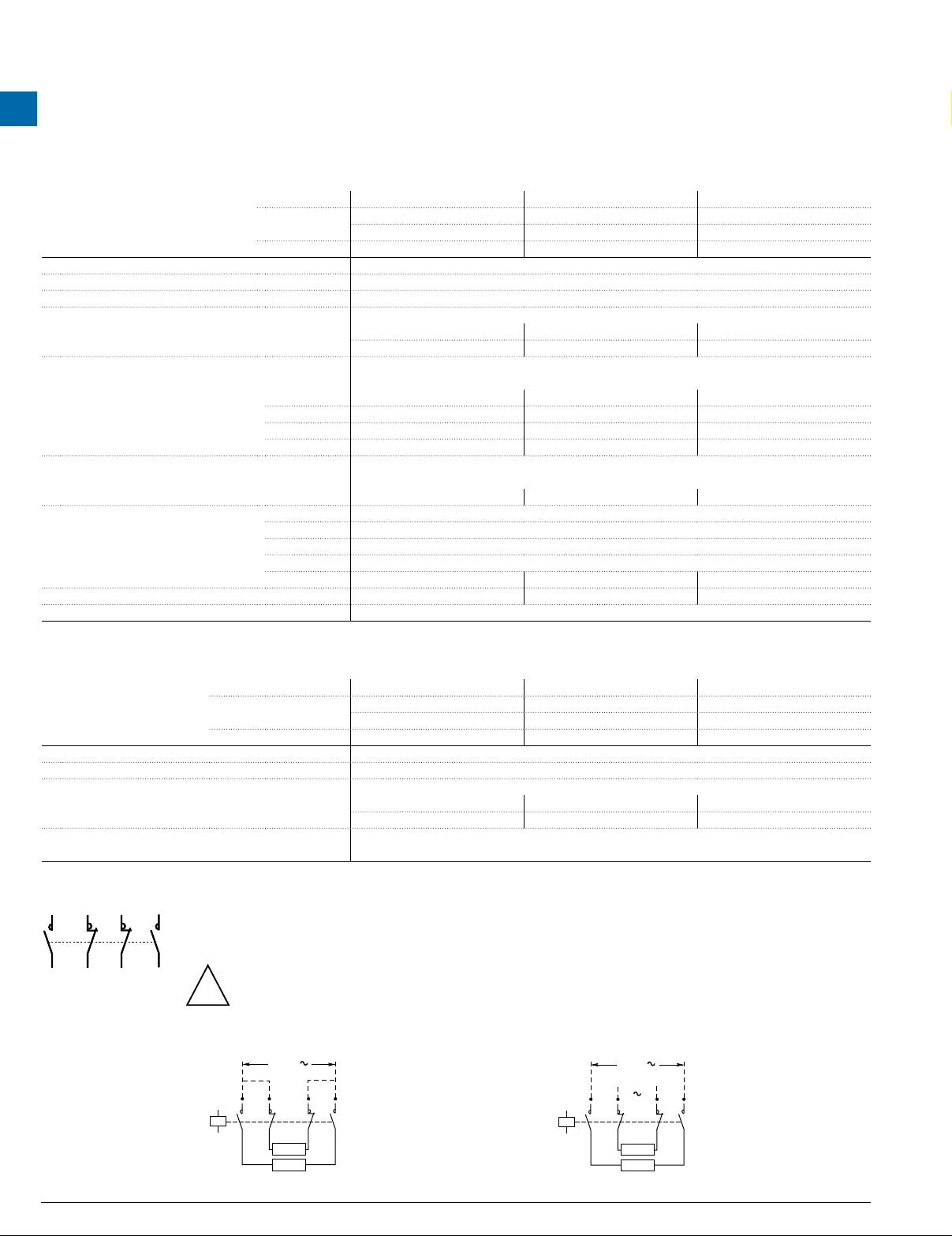
Remark for 4-pole contactors fitted with 2 N.O. + 2 N.C. main poles
7
R5
R3
1
These contactors are suitable for controlling 2 separate circuits, i.e. 2 loads with 2 separate supplies, or 1 circuit comprising
2 separate loads with a single supply (see diagrams below). When the contactor operates there is no mechanical overlapping
between the N.O. poles and the N.C. poles: BREAK before MAKE.
Block diagrams
– Single supply and 2 separate loads – 2 separate supplies and 2 separate loads
A1
1
AC operated
DC operated
A45 A50 A75
AE45 AE50 AE75
TAE45 TAE50 TAE75
AC / DC operated
AF45 AF50 AF75
UL 508, CSA C22.2 N°14
600 V
These contactors are not suitable for a reversing starter or for controlling a single load from 2 separate supplies.
Main
supply
Back-up
supply
7
R5
R3
1
R3
Supply
7
R5
A1
2
A2
Load
Load
R4
2
A2
Load
Load
8
R6
8
R6
R4
1.124 Low Voltage Products & Systems
1SXU000023C0202 Rev. A ABB Inc. • 888-385-1221 • www.abb.us/lowvoltage
Page 2
Magnet system characteristics
Pos
Contactor types
Coil operating limits
acc. to IEC 60947-4-1
AC control voltage
50/60 Hz
DC control voltage
Drop-out voltage
Voltage sag immunity
acc. to SEMI F47
Dips withstand
Operating time
Between coil energization and:
Between coil de-energization and:
Rated control circuit voltage Uc 48…250 V
Coil consumption
Rated control circuit voltage Uc 20…250 V DC
Coil consumption
General technical data
AF45...AF75
Coil & mounting characteristics
AC / DC operated
AC or DC supply
Average pull-in value
Average holding value
Average pull-in value
Average holding value
N.O. contact closing
N.C. contact opening
N.O. contact opening
N.C. contact closing
AF45 AF50 AF75
At θ ≤ 70 °C 0.85 x Uc min...1.1 x Uc max.
Please also refer to "Mounting characteristics and conditions for use"
210 VA
7 VA / 2.8 W
190 W
2.8 W
55 % of Uc min.
Conditions of use on request
≥ 20 ms
30…100 ms
27…95 ms
30…110 ms
35…115 ms
Across the line
Contactors
1
Mounting characteristics and conditions for use
Contactor types
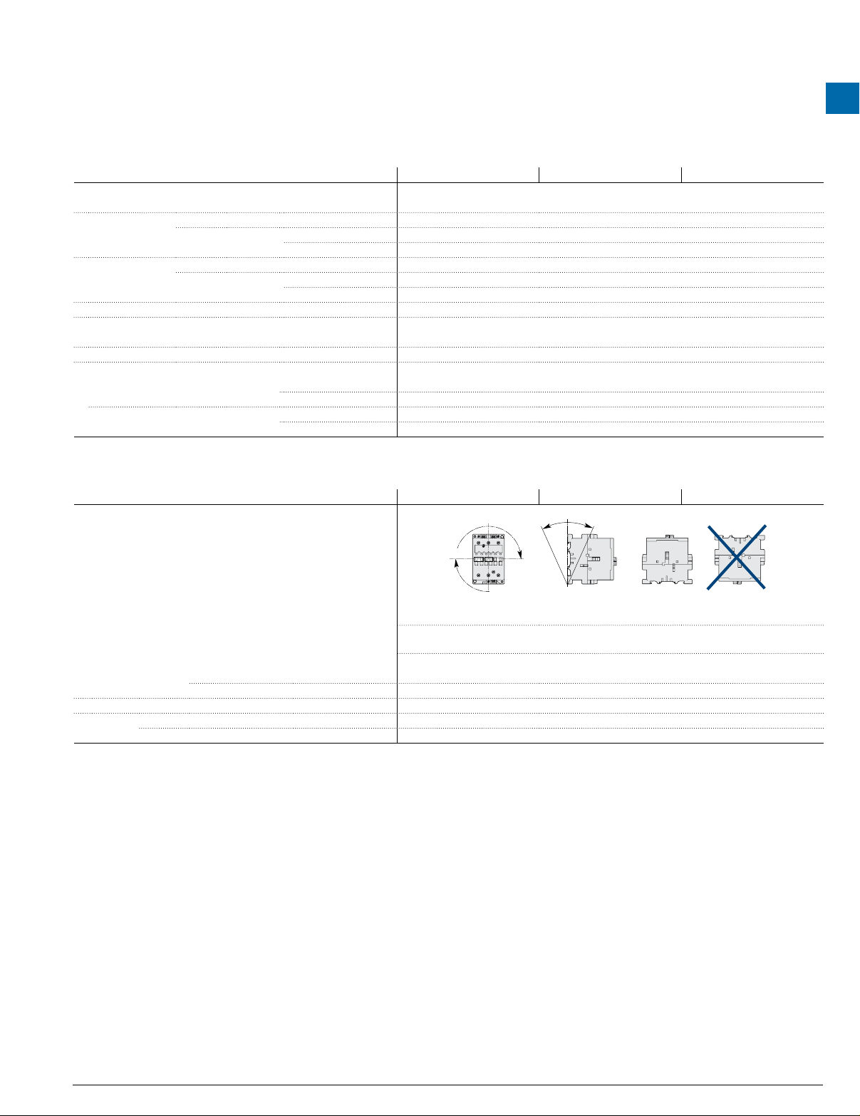
Mounting positions
Control voltage / Ambient temperature
Mounting 1, 1±30°, 2, 3, 4, 5
positions 6 Unauthorized
Mounting distances
Fixing
On rail according to IEC 60715, EN 60715 35 x 15 mm or 75 x 25 mm
By screws (not supplied) 2 x M6 screws placed diagonally
AC / DC operated
at θ ≤ 70 °C
AF45 AF50 AF75
. 2
Pos. 4
Pos. 1
Pos. 5 unauthorized for AF45-22-00, AF75-22-00 contactors
Max. and add-on N.O. or N.C. auxiliary contacts: see accessory fitting details for 4-pole contactor AF45 ... AF110
0.85 x Uc min…1.1 x Uc max.
The contactors can be assembled side by side
Pos. 3
+30° -30°
Pos. 1 ± 30°
Pos. 5
Pos. 6
Low Voltage Products & Systems 1.129
ABB Inc. • 888-385-1221 • www.abb.us/lowvoltage 1SXU000023C0202 Rev. A
Page 3

General technical data
C1
Across the line
1
Contactors
General technical data
Contactor types
Rated insulation voltage Ui
acc. to IEC 60947-4-1 1000 V
acc. to UL / CSA 600 V
Rated impulse withstand voltage Uimp.
Electromagnetic compatibility
Ambient air temperature close to contactor
Operation -40...+70 °C (1)
Storage -60...+80 °C
Climatic withstand
Maximum operating altitude (without derating)
Mechanical durability
Number of operating cycles 10 millions operating cycles (5 millions for AE... and TAE... contactors)
Max. switching frequency 3600 cycles/h (300 for AF...)
Shock withstand
acc. to IEC 60068-2-27 and EN 60068-2-27
Mounting position 1
A
(1) 55 °C max. for TAE... contactors.
(2) 3 g in open position for AF 45-22, AE 45-22, AF 75-22 and AE 75-22.
(3) 10 g for AF 45-22, AE 45-22, AF 75-22 and AE 75-22.
B1
A
B2
C2
A/E/F45...A/E/F75, 4-pole
AC operated
DC operated
AC / DC operated
Shock direction
4 N.O.
Main poles
2 N.O. + 2 N.C.
Main poles
A
B1
B2
C1
C2
A
B1
B2
C1
C2
A45 A50 A75
AE45 AE50 AE75
TAE45 TAE50 TAE75
AF45 AF50 AF75
8 kV
AF contactors complying with IEC 60947-1 / EN 60947-1 - Environment A
acc. to IEC 60068-2-30 and 60068-2-11 - UTE C 63-100 specification II
3000 m
1/2 sinusoidal shock for 11 ms: no change in contact position, closed or open position
20 g
10 g closed position / 5 g open position
15 g
20 g
20 g
20 g
10 g closed position / 5 g open position (2)
15 g (3)
20 g
20 g
1.132 Low Voltage Products & Systems
1SXU000023C0202 Rev. A ABB Inc. • 888-385-1221 • www.abb.us/lowvoltage
Page 4

General technical data
A/E/F45...A/E/F75
Terminal characteristics
Connecting characteristics
Contactor types
Main terminals
Connection capacity (min. ... max.)
Main conductors (poles)
Rigid Solid (≤ 4 mm²)
Stranded (≥ 6 mm²)
Flexible with ferrule
Bars or lugs
L
l
Connection capacity acc. to UL/CSA (Sol/Str)
Tightening torque Recommended 4.00 Nm / 35 lb.in
Max. 4.50 Nm
Auxiliary conductors
(built-in auxiliary terminals + coil terminals)
Rigid solid
Flexible with ferrule
Lugs
L
l
Connection capacity acc. to UL/CSA (Sol/Str)
Tightening torque Recommended 1.00 Nm / 9 lb.in
Max. 1.20 Nm
Degree of protection
acc. to IEC 60947-1 / EN 60947-1 and IEC 60529 / EN 60529
Main terminals IP10
Coil terminals IP20
Screw terminals
Main terminals M6
Coil terminals M3.5
AC operated
DC operated
AC / DC operated
1 x
2 x
1 x
2 x
L ≤
l >
1 or 2 x
1 x
2 x
1 x
2 x
L ≤
l >
1 or 2 x
Screwdriver type
Screwdriver type
A45 A50 A75
AE45 AE50 AE75
TAE45 TAE50 TAE75
AF45 AF50 AF75
Screw terminals with single connector
(13 x 10 mm)
6…50 mm²
6…25 mm²
6…35 mm²
6…16 mm²
-
AWG 8…1
1…4 mm²
1…4 mm²
1…2.5 mm²
0.75…2.5 mm²
8 mm
3.7 mm
AWG 18…14
Delivered in open position, screws of unused terminals must be tightened
Flat Ø 6.5 / Pozidriv 2
Flat Ø 5.5 / Pozidriv 2
Across the line
Contactors
1
Low Voltage Products & Systems 1.135
ABB Inc. • 888-385-1221 • www.abb.us/lowvoltage 1SXU000023C0202 Rev. A
 Loading...