

Page 1

Operation Manual
A135-H66
HT594610 English
Original Operation Manual
Chapter Document-ID
1 Introduction
2 Safety
3 Safety data sheet
4 Product description
HZTL4005_EN_G
HZTL4022_EN_E
HT594610
HZTL4030_EN_F
ABB Turbocharging
Page 2

Operating limits and replacement intervals
The recommended replacement intervals and the corresponding operating limits in chapter 3 are jointly defined
with the enginebuilder. This information is specific to the product.
Non-observance of the recommended replacement intervals and the operating limits increases the risk of unpredictable component failures.
Page 3

Operation Manual / 1 Introduction
Table of contents
Introduction
1 Introduction............................................................................................................ 2
1.1 Purpose of the manual.................................................................................................. 2
1.2 Symbols, definitions...................................................................................................... 3
1.3 Storage of new turbochargers and spare parts...................................................... 5
1.4 Contact information...................................................................................................... 7
© Copyright 2020 ABB. All rights reserved. HZTL4005_EN Rev.G March 2020
Page 4
Operation Manual / 1 Introduction
1 Introduction / 1.1 Purpose of the manual
1 Introduction
1.1 Purpose of the manual
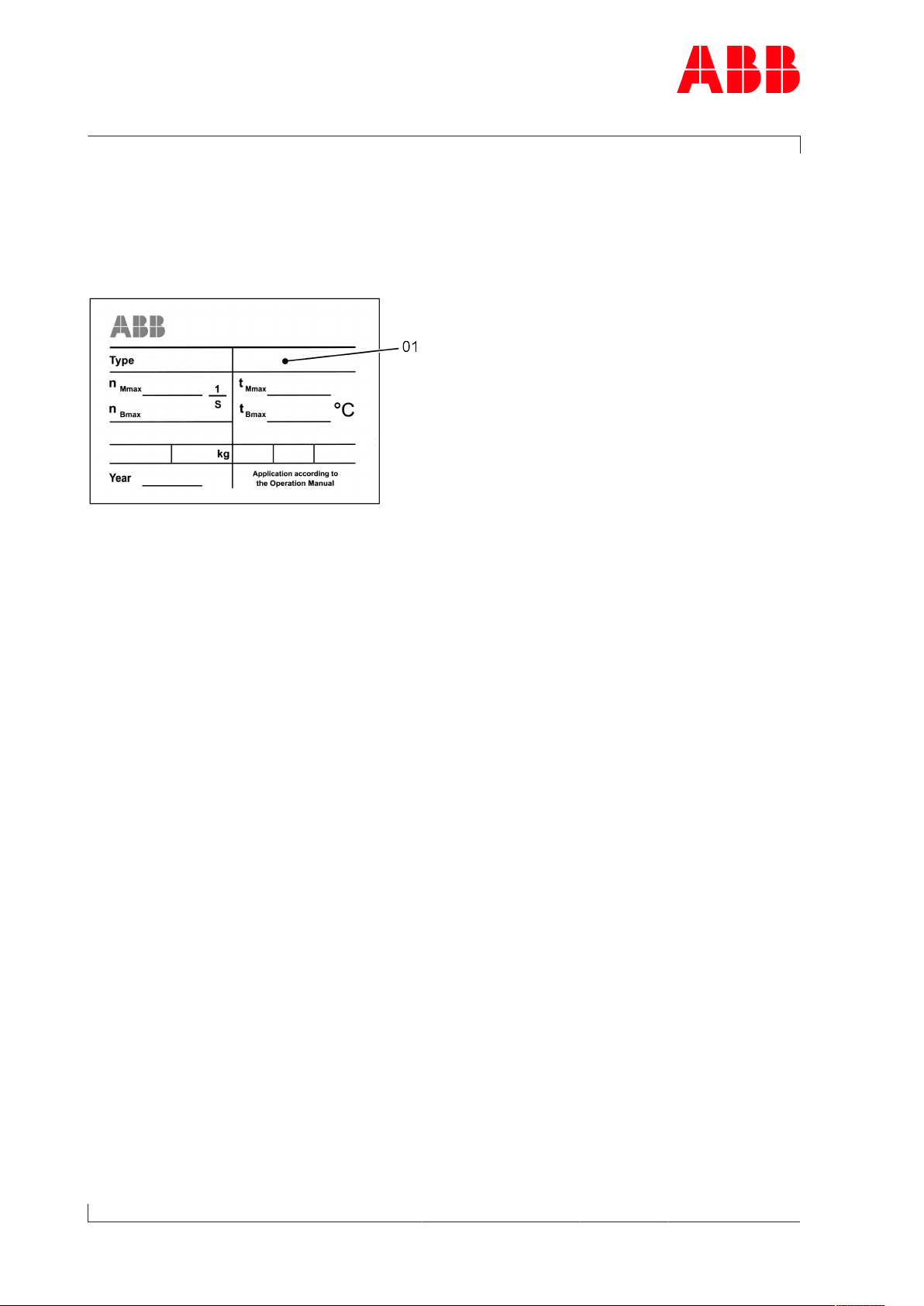
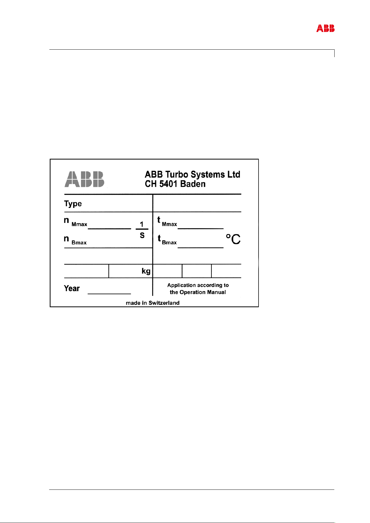
Fig.1: Serial number (01) on the rating plate
This Operation Manual belongs to the turbocharger with the identical serial number (01), see
chapter 3 (Safety data sheet) and the rating plate on the turbocharger.
Operation Manual
The Operation Manual explains the turbocharger and contains instructions for safe opera-
Page 2 / 7
tion.
The Operation Manual is a complement to and expansion of existing national regulations for
occupational safety, accident prevention and environmental protection.
Target group
The Operation Manual is aimed at engineers and trained mechanics responsible for the
proper operation of the engine and for the turbocharger connected to it.
Availability of the Operation Manual
The Operation Manual must be available where the turbocharger is used.
All persons operating or working on the turbocharger must have read and fully understood
the Operation Manual.
© Copyright 2020 ABB. All rights reserved. HZTL4005_EN Rev.G March 2020
Page 5

Operation Manual / 1 Introduction
1 Introduction / 1.2 Symbols, definitions
1.2 Symbols, definitions
Symbols
The following symbols are used in this document:
u Indicates an action step.
1. Indicates a numbered action step.
→Refers to a page number
Definition of Note
NOTICE
Note
The note provides advice which facilitates the work.
Definition of mandatory signs
Mandatory signs show the protective equipment to be worn for a task. The mandatory signs
are described in chapter Safety and must be complied with.
Definition of Caution / Warning
Caution and warning signs are described in chapter Safety.
ABB Turbocharging
ABB Switzerland Ltd, Turbocharging is identified as ABB Turbocharging or as ABB Turbo Systems in this document.
Official service stations of ABB Turbocharging
Official service stations are regularly audited and certified by ABB Turbocharging. See also
chapter Contact information →7.
Page 3 / 7
© Copyright 2020 ABB. All rights reserved. HZTL4005_EN Rev.G March 2020
Page 6

Operation Manual / 1 Introduction
1 Introduction / 1.2 Symbols, definitions
Definition of pictograms
The following pictograms can occur in this document. These point out actions that must be
taken in accordance with the meaning of the relevant pictogram.
Pictogram Meaning
Tighten with specified torque
Tighten over specified tightening angle
Hand-tight, tighten without tools
Oil
Apply screw locking paste (e.g. Loctite)
Apply high-temperature grease
Apply other paste in accordance with specifications
Oil free, grease free and dry
Affix
Measure
Page 4 / 7
Table1: Definition of pictograms
Note
Visually inspect
Please note text for numbered work step.
See document
Dispose of in an environmentally compatible, professional way and in compliance
with locally applicable regulations.
© Copyright 2020 ABB. All rights reserved. HZTL4005_EN Rev.G March 2020
Page 7
Operation Manual / 1 Introduction
1 Introduction / 1.3 Storage of new turbochargers and spare parts
1.3 Storage of new turbochargers and spare parts
Storage of new turbochargers and spare parts up to 6 months
New turbochargers and spare parts can be stored in sealed packaging without additional
mothballing measures for up to 6months from the date of delivery (marked by the VCI label
on the package).
Fig.2: Volatile Corrosion Inhibitor (VCI)
Only dry rooms in which the relative humidity is between 40…70 % and no condensation can
form are suitable for storage.
Storage of new turbochargers and spare parts for more than 6 months
WARNING
Protection of health when handling VCIs
VCI products are not hazardous in the sense of the Hazardous Substances
Ordinance. Nevertheless, the following points are to be observed when
handling VCIs:
u Observe specifications in the safety data sheet
u Ensure good room ventilation.
u Do not eat, drink or keep food at the workplace while working with VCIs.
u Clean hands and face after working with VCIs.
u For further information refer to www.branopac.com.
Wear safety gloves to protect against mechanical hazards.
The following mothballing measures are required every 6months:
u Open the package.
u Remove the VCI corrosion protection emitter from the package and replace it with a new,
identical VCI corrosion protection emitter. New VCI corrosion protection emitters can be
obtained at www.branopac.com.
Page 5 / 7
u Dispose of the old VCI corrosion protection emitter in an environmentally compatible
manner, professionally and in accordance with local regulations.
u Seal the package. The better the external seal is designed, the more permanent the pro-
tection.
© Copyright 2020 ABB. All rights reserved. HZTL4005_EN Rev.G March 2020
Page 8
Operation Manual / 1 Introduction
1 Introduction / 1.3 Storage of new turbochargers and spare parts
Long-term storage of turbochargers
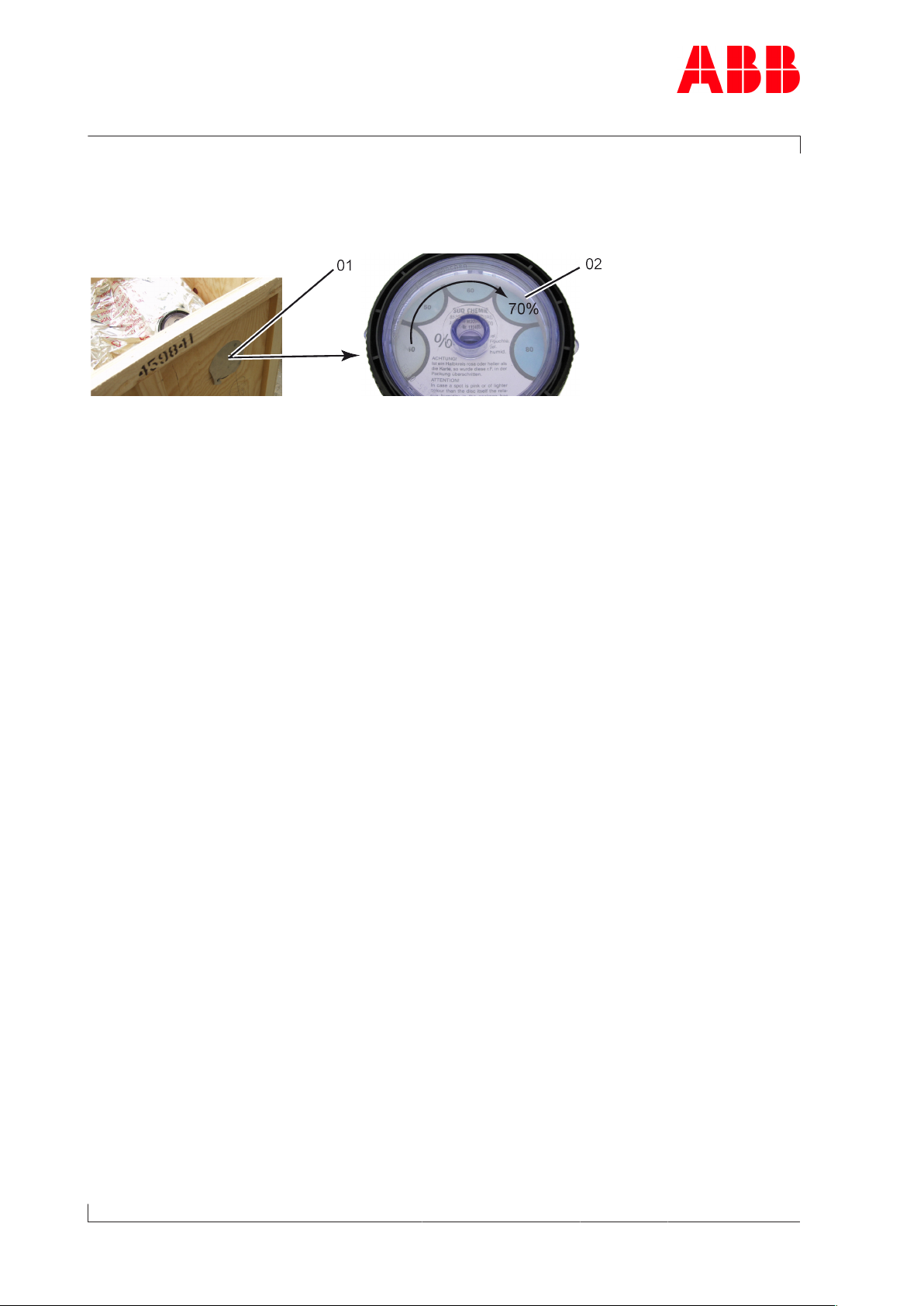
The turbochargers will be prepared for prolonged storage by ABB Turbo Systems on request. The package is equipped with a hygrometer (see illustration).
Fig.3: Package with hygrometer
The following measures are required every 6months:
u Check the hygrometer(02) in the sight-glass. There is an opening(01) in the wooden
crate which allows this check to be carried out. When the display field has changed colour
at the 70% level, the maximum permissible humidity has been exceeded. In this case the
turbocharger must be inspected by an ABB Turbocharging Service Station and repacked.
u Inspect the package for damage. If the package is damaged, the turbocharger must be in-
spected by an ABB Turbocharging Service Station and repacked.
After every 3 years the following work steps must be performed by an ABB Turbocharging
Service Station:
Page 6 / 7
¡ Inspect the components
¡ Replace the desiccant agent
¡ Repackage the components.
If the 70% display field of the hygrometer(02) has not changed colour and the package is
undamaged, the turbocharger can be placed into operation without any prior testing by an
ABB Turbocharging Service Station.
Unpacking turbochargers
The corrosion protection effect ends after the material is unpacked from the VCI package.
To avoid the formation of condensation, the surroundings and the content of the package
must have the same temperature during unpacking.
© Copyright 2020 ABB. All rights reserved. HZTL4005_EN Rev.G March 2020
Page 9

Operation Manual / 1 Introduction
1 Introduction / 1.4 Contact information
1.4 Contact information
Contact information for the ABB Turbocharging Service Stations is available online.
u Scan the QR code to access our website.
ABB Switzerland Ltd, Turbocharging
Bruggerstrasse 71a
CH-5401 Baden
Switzerland
www.abb.com/turbocharging
Page 7 / 7
© Copyright 2020 ABB. All rights reserved. HZTL4005_EN Rev.G March 2020
Page 10

Page 11

Operation Manual / 2 Safety / A130 - A155
Table of contents
Safety
1 Safety ...................................................................................................................... 2
1.1 Introduction .................................................................................................................... 2
1.2 CE conformity................................................................................................................. 2
1.3 Definition of mandatory signs .................................................................................... 3
1.4 Definition of safety instructions ................................................................................ 3
1.5 Intended use .................................................................................................................. 4
1.6 Deflagration on gas engines ....................................................................................... 5
1.7 Warning plates on the turbocharger......................................................................... 6
1.8 Turbocharger rating plate............................................................................................ 7
1.9 Periodic check of the pressure vessels..................................................................... 8
1.10 Lifting of loads .............................................................................................................. 9
1.11 Prerequisites for operation and maintenance....................................................... 10
1.12 Hazards during operation and maintenance ......................................................... 11
1.13 Safe operation.............................................................................................................. 13
1.14 Safe maintenance ........................................................................................................ 15
© Copyright 2017 ABB. All rights reserved. HZTL4022_EN Revision E May 2017
Page 12

Operation Manual / 2 Safety / A130 - A155
1 Safety / 1.1 Introduction
1 Safety
1.1 Introduction
Turbochargers manufactured by ABB reflect the state of the art. The respective safety and
health protection requirements are met. This ensures safe operation of the turbocharger.
Nevertheless, there may be some residual risks during operation of and work on the turbocharger which:
¡ Are caused by the turbocharger itself or its accessories.
¡ Are caused by the operating equipment used or supplies and materials.
¡ Are a consequence of insufficient compliance with safety instructions.
¡ Are a consequence of insufficient or inappropriate performance of maintenance and in-
spection work.
The operating company is responsible for defining measures that regulate safe access to
and safe handling of the turbocharger.
Page 2 / 18
All instructions contained in this chapter must be observed for safe and trouble-free operation of the turbocharger and during all work on the turbocharger.
All further safety instructions contained and specifically identified in every chapter of this
manual (Definition of safety instructions →3) must also be observed.
1.2 CE conformity
Information
ABB turbochargers comply with the Machinery Directive 2006/42/EC and are partly completed machinery as defined by Article 2 g in this directive.
© Copyright 2017 ABB. All rights reserved. HZTL4022_EN Revision E May 2017
Page 13
Operation Manual / 2 Safety / A130 - A155
1 Safety / 1.3 Definition of mandatory signs
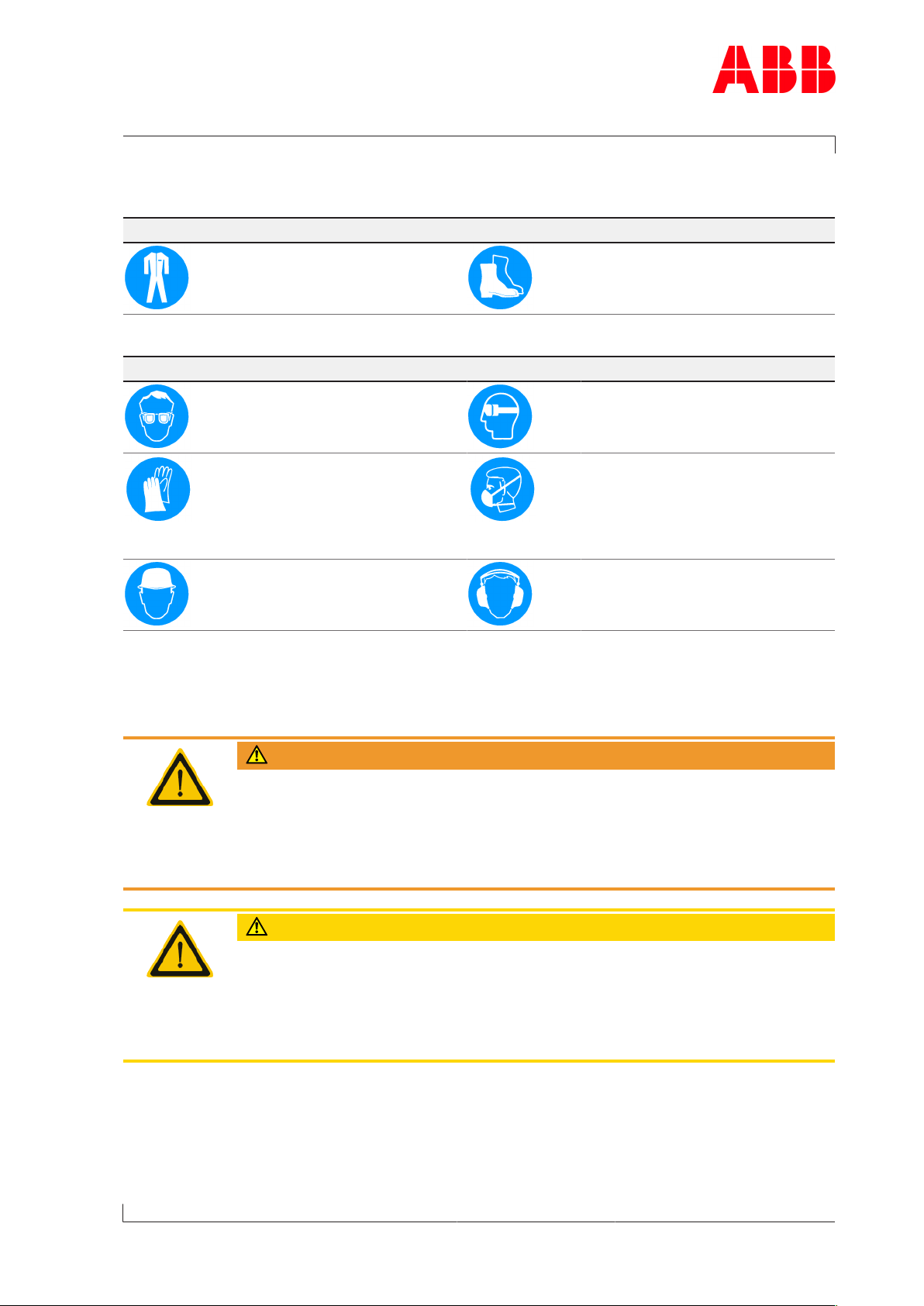
1.3 Definition of mandatory signs
To be worn at all times
Protective clothing Safety footwear to protect
against mechanical hazard and
risk of falling
Table1: Personal protective equipment to be worn at all times
To be worn specific to the respective task
Safety glasses Safety goggles
Safety gloves to protect
against
- Mechanical hazard
- Chemical hazard
- Thermal hazard
Safety helmet Ear protection
Table2: Personal protective equipment to be worn specific to the respective task
Respiratory mask to protect
against
- Dusts
- Gases
1.4 Definition of safety instructions
WARNING
Definition of Warning
Non-compliance or inaccurate compliance with working or operating instructions indicated by this symbol and the word WARNING can lead to serious injuries to personnel and even to fatal accidents.
u Warning signs must always be observed.
Page 3 / 18
CAUTION
Definition of Caution
Non-compliance or inaccurate compliance with working or operating instructions indicated by this symbol and the word CAUTION can lead to serious damage to engine or property with grave consequences.
u Caution signs must always be observed.
© Copyright 2017 ABB. All rights reserved. HZTL4022_EN Revision E May 2017
Page 14
Operation Manual / 2 Safety / A130 - A155
1 Safety / 1.5 Intended use
1.5 Intended use
Use on internal combustion engines in general
ABB turbochargers are intended for turbocharging internal combustion engines.
To ensure compliance with the machinery directive 2006/42/EC when using on gas engines,
the turbocharger must be operated in an engine room classified as "not at risk of explosion".
This is in accordance with the position paper [2] relating to ATEX issued by EUROMOT[1].
For use on pre-mix gas engines with ignitable propellents in the gas control system, the enginebuilder must implement appropriate safety measures for explosion protection [3] (such
as flame barriers in the inlet system, for example) to assure that there is no transient pressure increase exceeding a maximum of 12 bar before the turbocharger in case of a deflagration.
The turbocharger supplies the engine with the air volume or air/gas mixture and the associated charging pressure required for operation.
Page 4 / 18
The turbocharger is solely intended to be operated with a clockwise direction of rotation as
viewed from the turbine end.
The specific operating limits of the turbocharger were determined on the basis of information from the enginebuilder about the intended use. These data are given on the rating
plate.
ABB accepts no liability and rejects all warranty claims for any non-intended uses.
[1] Euromot = The European Association of Internal Combustion Engine Manufacturers
[2] Directive 94/9/EC concerning equipment and protective systems intended for use in
potentially explosive atmospheres (ATEX) The Euromot Position as of November
2003, ATEX Euromot Position 191103
[3] Guidelines for proper safety design of inlet systems on gas engines, RWTÜV Essen,
1991
WARNING
Unapproved operation
Any operation of the turbocharger outside of its operating limits can be hazardous to personnel.
u Only operate the turbocharger within the operating limits.
u Only trained personnel must operate the turbocharger.
The intended use of the turbocharger includes compliance with all regulations and conditions. In particular, the following must be observed:
¡ Operation Manual
¡ Instructions of the enginebuilder
© Copyright 2017 ABB. All rights reserved. HZTL4022_EN Revision E May 2017
Page 15

Operation Manual / 2 Safety / A130 - A155
1 Safety / 1.6 Deflagration on gas engines
State of the art
The turbocharger is designed and manufactured according to the state of the art and is safe
to operate.
Perfect condition
The turbocharger must only be used when it is in a technically flawless condition and operated in compliance with its intended use.
ABB excludes any liability for damage resulting from unauthorized modifications to the turbocharger or improper operation.
1.6 Deflagration on gas engines
ABB turbochargers can tolerate a deflagration with a transient pressure increase of 12bar.
After a deflagration event ABB Turbo Systems recommends verifying the following points on
the turbocharger:
¡ Position of the turbine and compressor casings to the bearing casing
¡ Shifting of the bearing casing in relation to the bracket
¡ Cracks in casings
If during external inspection anomalies are found or if a particularly strong deflagration
event has taken place, it is also recommended to check the bearings of the turbochargers
before the next start. An ABB Turbocharging Service Station should be instructed to carry
out this inspection.
Page 5 / 18
© Copyright 2017 ABB. All rights reserved. HZTL4022_EN Revision E May 2017
Page 16
Operation Manual / 2 Safety / A130 - A155
1 Safety / 1.7 Warning plates on the turbocharger
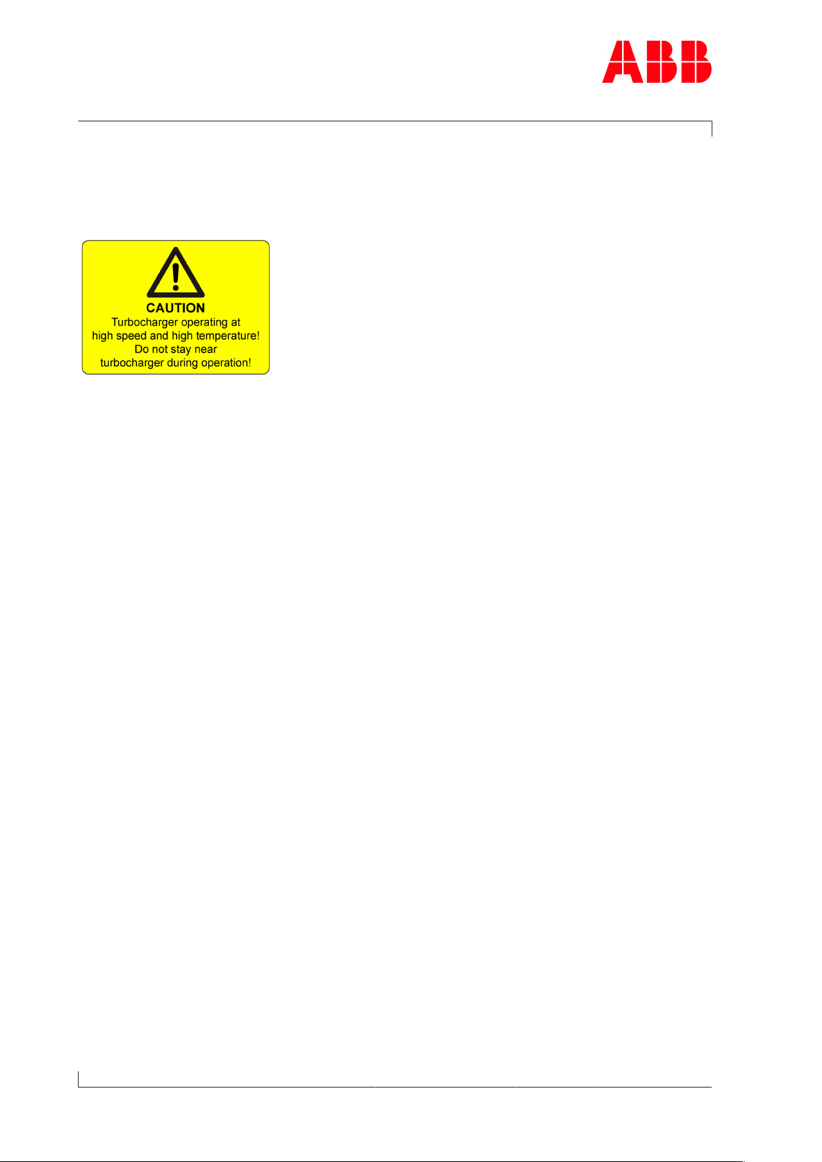
1.7 Warning plates on the turbocharger
Warning plates are attached to the turbocharger, which must be observed. The warning
plates must always be present in the intended locations and must be legible.
Fig.1: Warning plate
If warning plates are not present in the intended locations or are not legible, they must be
replaced with new warning plates. The necessary information can be found in the Operation
Manual, Chapter 4 Product description.
Page 6 / 18
Turbochargers supplied to the enginebuilder without insulation must be equipped later with
warning plates on the insulation. This is the responsibility of the enginebuilder.
© Copyright 2017 ABB. All rights reserved. HZTL4022_EN Revision E May 2017
Page 17
Operation Manual / 2 Safety / A130 - A155
1 Safety / 1.8 Turbocharger rating plate
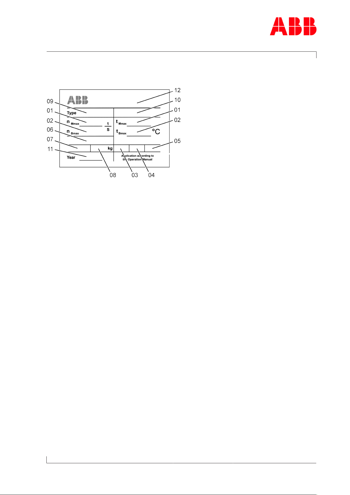
1.8 Turbocharger rating plate
Fig.2: Rating plate
Operating limits
01 Turbocharger operating limits at engine overload (110%).
In test rig operation only, unless otherwise agreed with the enginebuilder.
02 Turbocharger operating limits during operation
Recommended inspection and replacement intervals of turbocharger components
03 Inspection interval of plain bearings in 1000 h
04 Replacement interval of compressor in 1000 h
05 Replacement interval of turbine in 1000 h
Further data
06 Customer part number
07 Designation for special design
08 Weight of turbocharger in kg
09 Turbocharger type
10 Serial number
11 Year of construction of turbocharger
12 Manufacturing plant
Page 7 / 18
© Copyright 2017 ABB. All rights reserved. HZTL4022_EN Revision E May 2017
Page 18
Operation Manual / 2 Safety / A130 - A155
1 Safety / 1.9 Periodic check of the pressure vessels
Explanations regarding the rating plate
The recommended inspection and replacement intervals and the corresponding operating
limits are jointly defined with the enginebuilder. This information is specific to the system.
Page 8 / 18
Operation above the indicated values n
Bmax
, t
can considerably shorten the recommended
Bmax
replacement intervals. In such a case, we recommend that you contact the nearest official
service station of ABB Turbo Systems.
n
, t
Mmax
normally apply only when running at overload (110%) during trials on the engine
Mmax
test bed. These limit values can also be permitted during operation for special applications.
Operation above n
Mmax
and t
is not permitted.
Mmax
Non-observance of the recommended inspection and replacement intervals increases the
risk of unpredictable component failures.
Locations of the rating plates
The locations of the rating plates are defined in the Operation Manual, Chapter 4 Product
description.
1.9 Periodic check of the pressure vessels
The pressure vessels used by ABB Turbocharging, such as those for wet or dry cleaning, are
so-called "simple pressure vessels".
¡ The locally applicable legal regulations regarding periodic checks of the pressure vessels
must be observed.
¡ The operating company is responsible for the safe operation of the pressure vessel.
WARNING
Danger due to pressure vessels
The operating company must make sure the pressure vessels are in proper
working condition and monitor them. Necessary repair or maintenance work
must be performed promptly, and the required safety measures must be
taken.
u Pressure equipment must not be operated if defects are present.
© Copyright 2017 ABB. All rights reserved. HZTL4022_EN Revision E May 2017
Page 19
Operation Manual / 2 Safety / A130 - A155
1 Safety / 1.10 Lifting of loads
1.10 Lifting of loads
WARNING
Suspended loads
Loads that are not attached according to regulations can cause injury to
personnel or fatal accidents.
u Loads must always be fastened to properly functional lifting gear with a
sufficient load limit.
u Pay attention to the correct attachment of loads on the crane hook.
u People must not stand beneath suspended loads.
Wear safety gloves to protect against mechanical hazards.
Wear safety helmet.
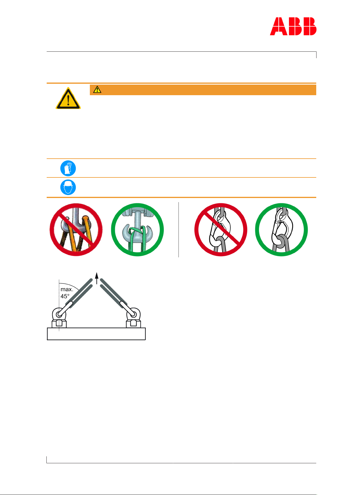
Fig.3: Attachment of loads on the crane hook
Fig.4: Attachment angle
If there are two or more suspension points, the attachment angle of 45° must not be exceeded. This prevents excessive loading due to diagonal pull.
u Before looping around the components of the turbocharger, let them cool down (max-
imum 80°C).
u Attach components of the turbocharger as described in the respective action steps.
u Use a suitable edge guard if there are sharp edges.
u The assembly devices must be completely screwed in and must not unscrew during use.
Page 9 / 18
u Use assembly devices only for the described applications.
u Put down dismantled components of the turbocharger in such a way that they cannot tip
over.
© Copyright 2017 ABB. All rights reserved. HZTL4022_EN Revision E May 2017
Page 20
Operation Manual / 2 Safety / A130 - A155
1 Safety / 1.11 Prerequisites for operation and maintenance
1.11 Prerequisites for operation and maintenance
Responsibility of the operating company
In awareness of its responsibility, the operating company must ensure that only authorised
personnel work on the turbocharger, who:
¡ Are versed in the general and locally applicable regulations for occupational safety and
accident prevention
¡ Are equipped with the prescribed personal protective equipment
¡ Have read and understood the Operation Manual
¡ Have been instructed in the use of the turbocharger.
The safety-conscious work of the personnel and adherence to the Operation Manual must be
checked periodically.
Suitable working materials and personal protective equipment must be kept in a perfect
condition.
Page 10 / 18
Only authorised personnel may remain in the vicinity of the turbocharger when the engine is
running.
Competence of personnel
The turbocharger must only be operated and serviced by trained and authorised personnel.
Basic mechanical training is a prerequisite.
Modifications to the turbocharger
Modifications to the turbocharger must be approved by ABB Turbo Systems.
WARNING
Use original parts
Operation of the turbocharger with non-original parts can impair the safety
of the turbocharger and can cause serious damage to property and injury to
personnel.
u Only use original parts from ABB Turbo Systems.
Original parts and accessories are specially designed by ABB Turbo Systems for the ABB turbochargers.
ABB accepts no liability for any damage resulting from the use of non-original parts and corresponding accessories.
© Copyright 2017 ABB. All rights reserved. HZTL4022_EN Revision E May 2017
Page 21
Operation Manual / 2 Safety / A130 - A155
1 Safety / 1.12 Hazards during operation and maintenance
1.12 Hazards during operation and maintenance
Noise hazards
The turbocharger's noise emission during operation is influenced by its installation and operating conditions. A noise level exceeding 85 dB(A) is harmful.
WARNING
Danger due to noise
Exposure to noise can harm the hearing system, impair health and the psychological state and may lead to lack of attention and irritation.
u When the engine is running, always wear ear protection.
u Always wear ear protection if the sound pressure level exceeds 85 dB(A).
Wear ear protection.
Hazards due to hot surfaces
Surfaces of the turbocharger, attached parts and operating fluids (lubricating oil) get hot
during operation. The surface temperature depends on the efficacy of the existing insulation. The temperature may rise to a level that can cause burns.
WARNING
Danger of burns
Touching hot surfaces or contact with hot operating fluids can cause burns.
u Do not touch hot surfaces. Observe the warning plate on the turbochar-
ger.
u Wear heat-resistant safety gloves and protective clothing.
u Wait for the turbocharger to cool down before carrying out any work.
Wear safety gloves to protect against thermal hazards.
Page 11 / 18
© Copyright 2017 ABB. All rights reserved. HZTL4022_EN Revision E May 2017
Page 22
Operation Manual / 2 Safety / A130 - A155
1 Safety / 1.12 Hazards during operation and maintenance
WARNING
Hot surfaces on the non-insulated turbocharger
Non-insulated turbochargers can cause serious injuries to personnel (burns).
The turbocharger is supplied with or without insulation in accordance with
the purchase order received from the enginebuilder. If supply is without insulation, the enginebuilder is responsible for providing the turbocharger
with proper insulation and for providing protection against contact with hot
surfaces.
u Compliance with the instructions and specifications given by the en-
ginebuilder to protect against hot turbocharger surfaces is compulsory.
Wear safety gloves to protect against thermal hazards.
Hazards due to rotating parts
Page 12 / 18
WARNING
Physical hazards
Contact with rotating parts can cause severe injury. The turbocharger must
never be used without the filter silencer or the air suction branch. With the
engine stopped, the rotor can rotate due to the stack draught alone.
u Operate the turbocharger in compliance with the specifications.
u Secure the rotor against unintentional rotation during maintenance.
Wear safety gloves to protect against mechanical hazards.
Hazards due to electrical installations (if present)
WARNING
Dangers during work on electrical installations
Electrical installations use voltages that can lead to severe injury to personnel or accidents resulting in fatalities.
At the same time, electrical or electronic components and parts can also be
damaged or destroyed.
u Only specially trained personnel should perform work on, or with, elec-
trical components.
u Observe national regulations.
© Copyright 2017 ABB. All rights reserved. HZTL4022_EN Revision E May 2017
Page 23

Operation Manual / 2 Safety / A130 - A155
1 Safety / 1.13 Safe operation
WARNING
Absence of grounding on electrical installations
Missing or incorrectly fitted grounding conductors can lead to severe injury
to personnel or accidents resulting in fatalities.
Electric shock or elevated electromagnetic disturbances can damage or destroy electrical and electronic components.
u Ground electrical installations properly with grounding conductors.
u Check the grounding connections on a regular basis and make sure they
are properly connected.
u Switch off the power supply before working on any electrical installations.
u After switching off the power supply, wait for 5 minutes to allow capacitors to discharge
and hot components to cool down.
u Ensure the power supply is switched off when working on electrical installations.
u Do not carry out any tests with regard to insulation resistance or voltage on the electrical
components.
1.13 Safe operation
Mechanical hazards during operation
During standard operation, no mechanical hazards are caused by the turbocharger itself if it
has been properly installed.
Safety during commissioning and operation
u Visually inspect your working environment before starting work.
u Remove any obstacles and objects littering the workplace.
u Check all pipes to and from the turbocharger for damage and leaks before commission-
ing.
u Check turbocharger for recognisable damage or defects every 12 hours of operation or at
least once a day.
u Report any damage and any alterations of operational characteristics to the responsible
department immediately.
u In case of damage, take the turbocharger out of operation immediately and safeguard
against accidental/unauthorised use.
u When switching on operating energy supplies (hydraulics, pneumatics, electricity), pay at-
tention to the risks that may occur as a consequence of this energy input.
Page 13 / 18
© Copyright 2017 ABB. All rights reserved. HZTL4022_EN Revision E May 2017
Page 24
Operation Manual / 2 Safety / A130 - A155
1 Safety / 1.13 Safe operation
WARNING
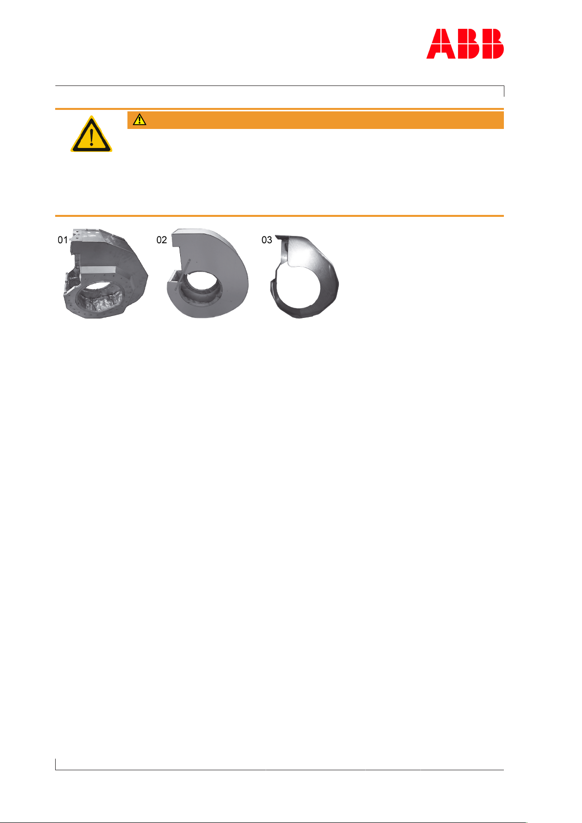
Burst protection and insulation
Operation without burst protection and insulation or with the wrong combination of burst protection and insulation can cause serious injuries to persons or even fatal accidents.
u Only operate the turbocharger with burst protection fitted and insulation
fitted in one of the following, permitted variants.
Fig.5
Page 14 / 18
Variant A Insulation(01) with integrated burst protection from ABB Turbo Systems.
Variant B Burst protection(03) and insulation (02)from ABB Turbo Systems.
Variant C Burst protection(03) from ABB Turbo Systems with appropriate insulation
from the enginebuilder.
© Copyright 2017 ABB. All rights reserved. HZTL4022_EN Revision E May 2017
Page 25
Operation Manual / 2 Safety / A130 - A155
1 Safety / 1.14 Safe maintenance
1.14 Safe maintenance
Occupational safety
WARNING
Injuries to persons
Severe injuries to personnel or fatal accidents can be caused by mechanical
influences as a consequence of hazardous and inadequate operational procedures or non-compliance with safety and health standards.
u When working on the turbocharger always wear safety footwear and pro-
tective clothing to protect against mechanical hazards.
u Keep personal protective equipment in perfect condition.
u Obey mandatory signs.
u Observe the general rules for occupational safety and prevention of acci-
dents.
u Only perform operations that are described in this manual.
u Only perform operations for which you have received instruction or train-
ing.
Wear safety footwear to protect against mechanical hazard and risk of falling.
Wear protective clothing.
WARNING
Risk of falling
When working on the turbocharger, there is a risk of falling.
u Do not climb onto the turbocharger or onto attached parts and do not
use them as climbing aids.
u Use suitable climbing aids and working platforms for work above body
height.
u Comply with the general accident prevention regulations.
u Only perform work on the turbocharger when you are in a physically and psychologically
stable condition.
u Only work with suitable tools, equipment and appliances that function properly.
u Power tools must be grounded and cables must be undamaged.
u Keep the workplace clean; clear away any loose objects and obstacles on the floor.
Page 15 / 18
u Keep the floor, equipment, and turbocharger clean.
u Have oil binding agents ready and provide or keep oil pans at hand.
u Clean up any spills.
u Have fire protection means and extinguishing agents available.
© Copyright 2017 ABB. All rights reserved. HZTL4022_EN Revision E May 2017
Page 26
Operation Manual / 2 Safety / A130 - A155
1 Safety / 1.14 Safe maintenance
Welding work in the vicinity of the turbocharger
u When performing welding work in the vicinity of the turbocharger, always cover the filter
silencer to prevent the filter mat from being damaged.
u Keep flammable objects and substances out of the vicinity of flying sparks.
u Cover all connections on the turbocharger so that no foreign objects can enter the tur-
bocharger.
u Wear personal protective equipment (PPE) for welding operations.
Safety during cleaning
If cleaning agents or solvents are used for cleaning, the corresponding material safety data
sheet and the safety instructions in section Hazards due to operating materials and supplies
must be observed.
u Observe the material safety data sheet for the cleaning agent or solvent.
u Wear personal protective equipment (PPE) according to the material safety data sheet.
Page 16 / 18
u Inspect the electric cables for abrasion and damage before and after your cleaning work.
Safety during disassembly, assembly, maintenance and repair
u Observe the procedures for set-up, service and inspection work and the inspection inter-
vals.
u Inform the operating staff before starting any service or repair work. Make sure the en-
gine is not started while work is being conducted on the turbocharger.
u Before taking off any cover or removing any guard from the turbocharger, switch off the
engine and wait until the turbocharger has come to a standstill.
u Make sure that the oil supply is interrupted, especially with an external oil supply.
u Only restart the engine after all parts have been properly fitted again and oil supply is en-
sured.
CAUTION
Mechanical operations on the turbocharger
Components of the turbocharger can be damaged or destroyed as a result
of improper procedures.
u Only perform operations that are described in this manual.
u Only perform operations for which you have received instruction or train-
ing.
Safety when taking out of operation or preparing for mothballing
u Secure rotor against turning. The rotor can rotate due to the stack draught alone.
u Observe the material safety data sheet for the cleaning and mothballing agents.
u Wear personal protective equipment (PPE) according to the material safety data sheet.
© Copyright 2017 ABB. All rights reserved. HZTL4022_EN Revision E May 2017
Page 27
Operation Manual / 2 Safety / A130 - A155
1 Safety / 1.14 Safe maintenance
Mechanical hazards when working on the turbocharger
WARNING
Physical hazards due to rotating parts
The rotor can rotate due to the stack draught alone. Contact with rotating
parts can cause severe injury.
u Secure rotor against turning.
WARNING
Mechanical hazards
Severe injuries to personnel or fatal accidents can be caused by mechanical
influences as a consequence of hazardous and inadequate operational procedures.
u Observe the general rules for occupational safety and prevention of acci-
dents.
u Ensure workplace safety.
u Only perform operations that are described in this chapter.
u Only perform operations for which you have previously received instruc-
tion or training.
Hazards due to operating materials and supplies
Operating materials and supplies are substances required for the operation of the turbocharger or for the performance of maintenance work. Oils, greases, coolants, detergents
and solvents, acids and similar substances can be classified as hazardous substances.
WARNING
Handling operating materials and supplies
Swallowing or inhaling vapours of operating materials and supplies or contact with them may be harmful to health.
u Do not breathe in these substances and avoid contact with the skin.
u Ensure proper ventilation.
u Observe the information in the material safety data sheet for the operat-
ing materials and supplies.
u Wear personal protective equipment (PPE) according to the material
safety data sheet.
u Comply with local legislation.
Wear safety goggles.
Wear safety gloves to protect against chemical hazards.
Page 17 / 18
Wear a respiratory mask to protect against gases.
© Copyright 2017 ABB. All rights reserved. HZTL4022_EN Revision E May 2017
Page 28
Operation Manual / 2 Safety / A130 - A155
1 Safety / 1.14 Safe maintenance
WARNING
Danger of fire or explosion
Flammable and combustible operating materials and supplies can catch fire
or resulting vapours can lead to an explosion.
u Observe the information in the material safety data sheet for the operat-
ing materials and supplies.
u Comply with local legislation.
u Do not allow any exposed flame or ignition source during cleaning work.
u Carry out cleaning in the open or provide sufficient ventilation.
CAUTION
Environmental hazard
Improper handling of operating materials and supplies can lead to environmental damage.
u Observe the information in the material safety data sheet for the operat-
ing materials and supplies.
u Comply with local legislation.
Page 18 / 18
Hazards due to the handling of insulation materials
WARNING
Danger from insulation materials
Dust or fibres from insulation materials can have adverse effects on the
health or cause irritations. Unsuitable and combustible insulation materials
are a fire hazard.
u Only use suitable and non-combustible insulation materials.
u Ensure good ventilation at the workplace.
u Avoid whirling up dust.
u Use dust-free tools and working methods.
u Remove package at the workplace only.
u Proceed with particular care when removing old insulation materials.
u Dispose of insulation materials properly and in an environmentally com-
patible manner in compliance with the legal regulations.
Wear safety goggles.
Wear a respiratory mask to protect against dusts.
Wear safety gloves to protect against chemical hazards.
© Copyright 2017 ABB. All rights reserved. HZTL4022_EN Revision E May 2017
Page 29
Operation Manual / A135-H66 / Safety data sheet
Safety data sheet
A135-H66 HT594610
A135-H66 HT594610
Page 1 / 1
864 680
844 650
X00067234
2020
270 16 50 50
© Copyright 2020 ABB. All rights reserved. HT594610 May 2020
Page 30

Page 31

Operation Manual / 4 Product description / A130-H.. - A140-H
Table of contents
Product description
1 Introduction............................................................................................................ 3
1.1 Essential information.................................................................................................... 3
1.2 Registered trademarks................................................................................................. 3
1.3 Related documents........................................................................................................ 3
1.4 Layout and function of the turbocharger ................................................................ 4
1.5 Warning plates on the turbocharger......................................................................... 6
1.6 Locations of the rating plates..................................................................................... 7
2 Removing and Installing........................................................................................ 8
2.1 Weight and transportation of the turbocharger.................................................... 8
2.2 Removing the turbocharger........................................................................................ 9
2.3 Installing the turbocharger........................................................................................ 13
3 Commissioning .................................................................................................... 20
3.1 Oil supply ...................................................................................................................... 20
3.2 Inspection procedures................................................................................................ 22
3.3 Commissioning after taking out of operation...................................................... 24
4 Monitoring operation .......................................................................................... 25
4.1 Oil pressure, oil temperature.................................................................................... 25
4.2 Exhaust gas temperature before turbine ............................................................... 27
4.3 Turbocharger speed................................................................................................... 28
5 Operation and service ......................................................................................... 31
5.1 Noise emission ............................................................................................................. 31
5.2 Service work ................................................................................................................. 33
5.3 Expected replacement intervals ............................................................................... 37
5.4 Stopping the engine................................................................................................... 39
6 Periodic maintenance work ................................................................................ 40
6.1 Foreword to maintenance......................................................................................... 40
6.2 Cleaning components mechanically ........................................................................ 41
7 Eliminating malfunctions.................................................................................... 51
7.1 Malfunctions when starting....................................................................................... 51
7.2 Malfunctions during operation ................................................................................ 52
7.3 Turbocharger is surging ............................................................................................ 55
7.4 Malfunctions when stopping.................................................................................... 56
7.5 Speed measurement system ..................................................................................... 57
8 Dismantling and fitting....................................................................................... 58
8.1 Introduction ................................................................................................................. 58
© Copyright 2020 ABB. All rights reserved. HZTL4030_EN Rev.F February 2020
Page 32

Operation Manual / 4 Product description / A130-H.. - A140-H
Table of contents
8.2 Weights of individual parts....................................................................................... 60
8.3 Removing the air inlets .............................................................................................. 62
8.4 Removing the gas outlet casing .............................................................................. 63
8.5 Removing the gas outlet flange............................................................................... 63
8.6 Removing the compressor casing........................................................................... 66
8.7 Pressing off the casing .............................................................................................. 68
8.8 Removing the cartridge group................................................................................. 69
8.9 Removing the nozzle ring........................................................................................... 71
8.10 Installing the cartridge group on the service support ......................................... 72
8.11 Measuring clearance A and B..................................................................................... 73
8.12 Nozzle ring compression PD..................................................................................... 74
8.13 Installing the nozzle ring ............................................................................................ 75
8.14 Installing the cartridge group .................................................................................. 76
8.15 Installing the compressor casing ............................................................................ 78
8.16 Measuring radial clearances N and R ...................................................................... 80
8.17 Installing the air inlets ................................................................................................ 81
8.18 Installing the gas outlet flange ................................................................................ 82
8.19 Installing the gas outlet casing ................................................................................ 82
8.20 Table of tightening torques...................................................................................... 83
9 Taking out of operation at short notice ........................................................... 84
9.1 Possible emergency repairs...................................................................................... 84
9.2 Installing the replacement turbocharger............................................................... 85
9.3 Installing the replacement cartridge group .......................................................... 85
10 Mothballing the turbocharger ............................................................................ 86
10.1 Taking the engine out of operation for up to 12months ................................... 86
10.2 Taking the engine out of operation for more than 12months.......................... 87
11 Disposing of turbocharger components .......................................................... 88
12 Spare parts ........................................................................................................... 89
12.1 Ordering spare parts.................................................................................................. 89
12.2 Required customer spare part set (97070)............................................................ 89
12.3 View of turbocharger with part numbers .............................................................. 90
Figures................................................................................................................... 92
Tables .................................................................................................................... 93
© Copyright 2020 ABB. All rights reserved. HZTL4030_EN Rev.F February 2020
Page 33

Operation Manual / 4 Product description / A130-H.. - A140-H
1 Introduction / 1.1 Essential information
1 Introduction
1.1 Essential information
Design variants
This document is valid for different design variants of turbochargers. There may be sections
and descriptions of components that are not relevant for a specific turbocharger variant.
Please contact an ABB Turbocharging Service Station if you have any questions regarding a
design variant (see Contact information at www.abb.com/turbocharging).
Accuracy of illustrations
The illustrations in this document are general in nature and intended for ease of understanding. Differences in detail are therefore possible.
1.2 Registered trademarks
The trademarks of outside companies are used in this document. These are marked with the
® symbol.
1.3 Related documents
Chapter Document number
Operation Manual / 1 Introduction HZTL4005
Operation Manual / 2 Safety HZTL4022
Operation Manual / 3 Safety data sheet *) Serial number of the turbocharger
Table1: Related documents
*) This chapter is only available in serialised operation manuals.
Page 3 / 93
© Copyright 2020 ABB. All rights reserved. HZTL4030_EN Rev.F February 2020
Page 34

Operation Manual / 4 Product description / A130-H.. - A140-H
1 Introduction / 1.4 Layout and function of the turbocharger
1.4 Layout and function of the turbocharger
Page 4 / 93
Fig.1: Layout and function of the turbocharger
01 Air suction branch 08 Gas outlet flange
02 Compressor casing 09 Nozzle ring
03 Diffuser 10 Turbine casing
04 Bearing casing 11 Turbine-end bearing flange
05 Axial thrust bearing 12 Compressor-end bearing flange
06 Radial plain bearing 13 Compressor wheel
07 Turbine
© Copyright 2020 ABB. All rights reserved. HZTL4030_EN Rev.F February 2020
Page 35

Operation Manual / 4 Product description / A130-H.. - A140-H
1 Introduction / 1.4 Layout and function of the turbocharger
Mode of operation
The turbocharger is a turbomachine and consists of the following main components:
¡ Turbine
¡ Compressor.
The exhaust gases of the internal combustion engine flow through the turbine casing(10)
and the nozzle ring(09) onto the turbine(07). The turbine(07) uses the energy contained in
the exhaust gas to drive the rotor and, hence, the compressor wheel(13). The exhaust gases
then reach the atmosphere through the exhaust gas pipe connected to the gas outlet
flange(08).
The compressor wheel(13) sucks in fresh air through the air suction branch (01). In the compressor wheel (13), the energy required for building up the pressure is transferred to the air.
By flowing through the diffuser(03) and the compressor casing(02), the air is compressed
further and is then directed to the engine cylinders.
The rotor runs in two radial plain bearings(06) which are located in the bearing casing(04)
between compressor and turbine. The axial thrust bearing(05) is located between the two
radial plain bearings.
The plain bearings are connected to a central lubricating oil duct which is normally supplied
by the lubricating oil circuit of the engine. The oil outlet always lies at the deepest point of
the bearing casing(04).
1.4.1 Function of the compressor wheel cooling
Fig.2: Compressor wheel cooling
Depending on the application of an A100 radial turbocharger, the turbocharger is equipped
with compressor wheel cooling. With compressor wheel cooling, after the compressor air
has cooled down by passing through the charge air cooler on the engine side, it is supplied
to the turbocharger for cooling the compressor wheel. Cooling of the compressor wheel is
compulsory to ensure the reliability and replacement intervals for the relevant operating
conditions. In the turbocharger version with compressor wheel cooling, the cooling air is
supplied through a lateral connection in the bearing casing (X).
Page 5 / 93
In addition, the turbocharger version with compressor wheel cooling is indicated by the turbocharger type (H6..) on the rating plate.
© Copyright 2020 ABB. All rights reserved. HZTL4030_EN Rev.F February 2020
Page 36

Operation Manual / 4 Product description / A130-H.. - A140-H
1 Introduction / 1.5 Warning plates on the turbocharger
1.5 Warning plates on the turbocharger
Warning plates are affixed at the following locations:
Page 6 / 93
Fig.3: Warning plate locations
If warning plates are not present in the designated locations or not readable, proceed as follows:
u Order new warning plates from ABB Turbocharging Service Stations.
u Remove any warning plates that have become unreadable.
u Clean and degrease the areas designated for the warning plates.
u Fit new warning plates and remove protective sheets.
Turbochargers supplied to the enginebuilder without insulation must be equipped later with
warning plates on the insulation. This is the responsibility of the enginebuilder.
© Copyright 2020 ABB. All rights reserved. HZTL4030_EN Rev.F February 2020
Page 37

Operation Manual / 4 Product description / A130-H.. - A140-H
1 Introduction / 1.6 Locations of the rating plates
1.6 Locations of the rating plates
Fig.4: Locations of the rating plates
One rating plate (01) each is attached on the left and the right side of the turbocharger bearing casing.
Page 7 / 93
© Copyright 2020 ABB. All rights reserved. HZTL4030_EN Rev.F February 2020
Page 38

Operation Manual / 4 Product description / A130-H.. - A140-H
2 Removing and Installing / 2.1 Weight and transportation of the turbocharger
2 Removing and Installing
2.1 Weight and transportation of the turbocharger
Lifting gear with a sufficient load limit must be used for removing, installing and transporting the turbocharger. The weight specified below applies to the heaviest variant possible.
Depending on the specification, the weight specified on the rating plate may be lower than
the standard value specified here.
Page 8 / 93
Fig.5: Transportation of the turbocharger
Product Weight of complete turbocharger unit [kg]
A130-H 190
A135-H 270
A140-H 460
Table2: Weight of complete turbocharger unit
© Copyright 2020 ABB. All rights reserved. HZTL4030_EN Rev.F February 2020
Page 39

Operation Manual / 4 Product description / A130-H.. - A140-H
2 Removing and Installing / 2.2 Removing the turbocharger
2.2 Removing the turbocharger
u Disconnect all pipes according to the instructions of the enginebuilder.
u If present: Loosen and remove the compressor wheel cooling connection.
Seal the compressor wheel cooling connection (01).
Fig.6: Removing the turbocharger
A Position of expansion sleeves
B Clamping nut
C Standard nut
u Apply penetrating oil to thread of stud (02) and nut and let it work in.
Do not apply penetrating oil to the pressure screws of the clamping nut(B).
u If present: Disconnect the plug to the speed sensor (86505) and secure the rolled-up
cable on the turbocharger. This protects the plug from being crushed.
u If present: Detach the support(61301) from the engine support.
Depending on the bracket version(04), positioning pins(05) can be used for positioning and
safeguarding against wrong fitting of the turbocharger. Therefore the turbocharger must always be removed from and installed on the bracket vertically.
The gas outlet casing(61001) can remain fitted in the exhaust gas pipe if the locking nuts
are accessible. Otherwise the complete turbocharger unit including gas outlet casing must
be removed.
Page 9 / 93
© Copyright 2020 ABB. All rights reserved. HZTL4030_EN Rev.F February 2020
Page 40

Operation Manual / 4 Product description / A130-H.. - A140-H
2 Removing and Installing / 2.2 Removing the turbocharger
2.2.1 Fastening of the turbocharger
WARNING
Risk of scalding from hot water
If the water connections are removed immediately after taking the turbocharger out of operation, the hot cooling water that flows out can cause
scalding if it comes into contact with the skin.
u Allow turbocharger to cool down before removing the water pipes.
u Wear safety gloves to protect against thermal hazards.
Wear safety gloves to protect against mechanical hazards.
CAUTION
Freezing of the cooling water in the bearing casing
Serious damage to property can be the consequence if the cooling water
freezes in the pipes and in the bearing casing.
u For transport and storage of the turbocharger, drain the cooling water in
the bearing casing via two openings of the water connections.
Page 10 / 93
Manual loosening
To remove the turbocharger from the bracket, proceed as follows:
u Loosen and remove water connections. Close the openings of the water connections with
screw plugs.
u Attach lifting gear to the suspension eye.
u Loosen and remove nuts(C).
Hydraulic loosening (round special nut)
If the turbocharger was fitted by the enginebuilder using a hydraulic tool, disassembly is
also done using a hydraulic tool (see instructions of the enginebuilder).
When doing this, proceed as follows:
u Attach lifting gear to the suspension eye.
u Remove the turbocharger.
u Cover the oil connections (03) at the engine side to protect against contamination.
© Copyright 2020 ABB. All rights reserved. HZTL4030_EN Rev.F February 2020
Page 41

Operation Manual / 4 Product description / A130-H.. - A140-H
2 Removing and Installing / 2.2 Removing the turbocharger
2.2.2 Loosening the clamping nut
CAUTION
Incorrect procedure can make loosening impossible
If individual pressure screws are fully relieved, the pressure screws can become compressed, making it impossible to loosen them.
u Comply with the following steps for loosening the pressure screws.
CAUTION
Do not clean pressure screws
The pressure screws are equipped with a permanent sliding layer that must
not be removed. In case of non-compliance, it cannot be ensured that the
necessary tension force is reached.
u Do not clean pressure screws.
u Do not lubricate pressure screws.
If a screw jams, the previously loosened screw must be tightened again a little.
Fig.7: Loosening the clamping nut
1. Working in a circle, break loose each pressure screw (≤20°).
2. Working in a circle, loosen each pressure screw by 45° in 4 rounds.
3. Working in a circle, loosen each pressure screw by 90° in 1...5 rounds until all of the pressure screws have been relieved.
u Loosen clamping nut by hand.
Page 11 / 93
© Copyright 2020 ABB. All rights reserved. HZTL4030_EN Rev.F February 2020
Page 42

Operation Manual / 4 Product description / A130-H.. - A140-H
2 Removing and Installing / 2.2 Removing the turbocharger
2.2.3 Putting down the turbocharger
WARNING
Risk of tipping
If the turbocharger is not positioned stably, it may tip over. This can result in
serious personal injury.
u Place the turbocharger on a clean, level support.
u Secure the turbocharger to prevent it from tipping over by using wooden
beams and wedges and by taking the centre of gravity into account.
Page 12 / 93
Fig.8: Putting down the turbocharger
u Remove turbocharger from engine support, set it down properly in an appropriate place
and secure it.
u Close or cover the openings of the turbocharger and support.
© Copyright 2020 ABB. All rights reserved. HZTL4030_EN Rev.F February 2020
Page 43

Operation Manual / 4 Product description / A130-H.. - A140-H
2 Removing and Installing / 2.3 Installing the turbocharger
2.3 Installing the turbocharger
2.3.1 Inserting gaskets into the bracket
CAUTION
Inserting the gaskets
Gaskets that are forgotten, damaged or improperly inserted will lead to oil
leaks.
u Always use new gaskets and insert them carefully into the slot.
The oil is supplied(02) and drained(03) through the bracket (01).
The necessary sealing is provided by O-rings. The O-rings are not included in the ABB Turbo
Systems scope of delivery.
Fig.9: Inserting gaskets into the bracket
01 Bracket 04 Slot for O-ring
02 Oil supply 05 O-rings
03 Oil drain 06 Pin (optional)
Pin(06) as installation safety device
Turbochargers can have an oil inlet either on their right or left side; the oil inlet position can
be different for the turbocharger fitted on the left and on the right engine bank.
A pin can be installed in every support as an installation safety device to prevent inadvertent
incorrect fitting. This pin fits into the respective slot on the foot of the bearing casing. Instructions of the enginebuilder must be observed.
Page 13 / 93
© Copyright 2020 ABB. All rights reserved. HZTL4030_EN Rev.F February 2020
Page 44

Operation Manual / 4 Product description / A130-H.. - A140-H
2 Removing and Installing / 2.3 Installing the turbocharger
2.3.2 Fitting threaded rods
Fig.10: Fitting threaded rods onto the bracket
1. Lightly oil the surfaces of the threaded rods(02) to be screwed in.
2. Screw the threaded rods into the bracket with the aid of locknuts(01).
3. Remove nuts(01) again.
Page 14 / 93
Requirements for the threaded rods
Fig.11: Requirements for threaded rods
Product Diameter
Threaded rod
[mm]
A130-H Ø 16 / M16 10.9 / 12.9 ≥ 30 250
A135-H Ø 20 / M20 10.9 / 12.9 ≥ 30 325
A140-H Ø 24 / M24 10.9 / 12.9 ≥ 70 410 … 420
Table3: Requirements for threaded rods
Material
DIN / ISO 898
(Part 1)
Thread length
L1[mm]
Length of
threaded rod
L2 [mm]
Fastening material, scope of delivery
The threaded rods and nuts for fastening the turbocharger on the bracket are not included
in the ABB Turbo Systems scope of delivery.
The clamping nuts are included in the ABB Turbo Systems scope of delivery.
© Copyright 2020 ABB. All rights reserved. HZTL4030_EN Rev.F February 2020
Page 45

Operation Manual / 4 Product description / A130-H.. - A140-H
2 Removing and Installing / 2.3 Installing the turbocharger
2.3.3 Placing the turbocharger on the bracket
Fig.12: Placing the turbocharger on the bracket
B Clamping nut
C Standard nut
u Make sure that covers of the oil and water connections are removed.
1. Make sure that the O-rings(03) are undamaged and positioned correctly in the slots.
2. Clean the expansion bushes(42190) and the contact surfaces of the expansion bushes in
the bearing casing.
3. Attach the lifting gear to the suspension eye of the bearing casing(42001) and loop
around the gas outlet casing.
4. Position the turbocharger on the bracket(04) and align it. If present, pay attention to the
positioning pin(05) in the bracket.
5. When fixing with a standard nut (C), fit the expansion bushes in the correct position in
the slot.
Safeguard against wrong fitting (only for water-cooled bearing casings)
Depending on the bracket version(04), two positioning pins(05) can be used for positioning
and safeguarding against wrong fitting of the turbocharger. Therefore the turbocharger
must always be removed from and installed on the bracket vertically.
u Observe the instructions for the fastening variant at hand.
Page 15 / 93
¡ Fastening the turbocharger with a standard nut →16 (A130-A140)
¡ Fastening the turbocharger with a clamping nut →17 (only A140)
© Copyright 2020 ABB. All rights reserved. HZTL4030_EN Rev.F February 2020
Page 46

Operation Manual / 4 Product description / A130-H.. - A140-H
2 Removing and Installing / 2.3 Installing the turbocharger
2.3.4 Fastening the turbocharger with a standard nut
u Fit the nuts and tighten them according to variant 1 or 2 in the table below.
Page 16 / 93
Product Through hole in
bearing casing
[mm]
A130 Ø17 M16 280 110
A135 Ø 21 M20 560 175
A140 Ø 25 M24 960 250
Table4: Tightening torque for standard nuts
Fixing screws
[mm]
Variant 1: Tightening
torques [Nm] **)
Variant 2: Hy-
draulic pre-ten-
sioning forces [kN]
**) When the turbocharger is mounted on the engine support, the bolt threads and screw
heads must be lightly oiled (assumed friction coefficient µ = 0.12 for tightening torque)
u Remove the lifting gear.
© Copyright 2020 ABB. All rights reserved. HZTL4030_EN Rev.F February 2020
Page 47

Operation Manual / 4 Product description / A130-H.. - A140-H
2 Removing and Installing / 2.3 Installing the turbocharger
2.3.5 Fastening the turbocharger with a clamping nut
Preparation for tightening
CAUTION
Do not clean pressure screws (04)
The pressure screws are equipped with a permanent sliding layer that must
not be removed.
Do neither clean nor lubricate the pressure screws. In case of non-compliance, it cannot be ensured that the necessary tension force is reached.
u Do not clean pressure screws.
u Do not lubricate pressure screws.
In order to correctly fit the clamping nuts, the pressure screws (04) must not protrude from
the clamping nuts (03) in the direction of the thrust washer (02).
u Make sure the pressure screws do not protrude in the direction of the thrust washer.
Fig.13: Preparing the clamping nut for the tightening procedure
1. Check whether the expansion bushes (42190) with recess are correctly positioned and do
not touch the flange of the core hole cover (A).
2. Clean the thread of the bolt (01) and the contact surface.
3. Lightly oil the bolt thread.
4. Position the thrust washer (02) in place.
Page 17 / 93
5. Tighten clamping nut (03) by hand.
6. Unscrew clamping nut (03) by ¼ of a turn (90°).
The distance between the thrust washer and the clamping nut is now about 1 mm.
© Copyright 2020 ABB. All rights reserved. HZTL4030_EN Rev.F February 2020
Page 48

Operation Manual / 4 Product description / A130-H.. - A140-H
2 Removing and Installing / 2.3 Installing the turbocharger
Tightening pressure screws
Page 18 / 93
Fig.14: Tightening pressure screws
Product Fixing screw [mm] Tightening torques [Nm]
A140 M24 35
Table5: Torque-controlled tightening of the pressure screws
1. Screw in pressure screws crosswise by hand until reaching the stop.
2. Tighten pressure screws crosswise to 50% of the tightening torque specified in the
table.
3. Tighten pressure screws crosswise to 100% of the tightening torque specified in the
table.
4. Work in a circle to tighten all pressure screws to 100% of the tightening torque specified
in the table.
5. Tighten pressure screws to 100% in 5…7 rounds until the required residual tightening
angle of <20° is achieved.
© Copyright 2020 ABB. All rights reserved. HZTL4030_EN Rev.F February 2020
Page 49

Operation Manual / 4 Product description / A130-H.. - A140-H
2 Removing and Installing / 2.3 Installing the turbocharger
2.3.6 Connecting the turbocharger
u Connect the cable to the speed sensor (86515).
u Connect all exhaust gas, water and air lines according to the instructions of the engineb-
uilder.
Version with compressor wheel cooling
CAUTION
Failure of compressor wheel cooling
Any prolonged failure of the compressor wheel cooling will shorten the replacement interval of the compressor wheel.
u Make sure there is an uninterrupted supply of cooling air during opera-
tion.
Fig.15: Connecting the compressor cooling air intake
u Remove the screw plug on the connection for the compressor wheel cooling (06) and fit
the cooling air line.
2.3.7 Attaching the support
Fig.16: Attaching the support
Page 19 / 93
u If present: Attach support (61301) to engine support or to a connecting piece.
© Copyright 2020 ABB. All rights reserved. HZTL4030_EN Rev.F February 2020
Page 50

Operation Manual / 4 Product description / A130-H.. - A140-H
3 Commissioning / 3.1 Oil supply
3 Commissioning
3.1 Oil supply
3.1.1 Introduction
In all operating states, a functioning and carefully executed oil supply is an important prerequisite for trouble-free operation of the turbocharger.
The lubrication of the turbocharger is usually carried out with oil from the engine oil circulation.
u Comply with the enginebuilder's specifications regarding the selection of lubricating oil
and the oil change intervals.
3.1.2 Oil filtering
Page 20 / 93
Filtering the lubricating oil with a filter mesh width of ≤0.034mm is sufficient for this turbocharger.
3.1.3 Oil pressure
Comply precisely with the oil pressure before the turbocharger for trouble-free operation.
Different oil pressures must be taken into account here for different operating states, such
as, for example, idling mode and when the engine is started.
The admissible values are specified in chapter Monitoring operation →25.
3.1.4 Starting the engine for the first time after a
turbocharger or engine overhaul
When starting the engine for the first time after a turbocharger or engine overhaul, proceed
as follows:
u Switch on the pre-lubrication pump.
u Build up oil pressure (see Table6: Lubricating oil pressure at oil inlet before turbocharger
→25).
u Do not exceed a pre-lubrication time of 2minutes.
u Start the engine.
u Let the pre-lubrication pump run until the pump driven by the engine generates sufficient
pressure.
© Copyright 2020 ABB. All rights reserved. HZTL4030_EN Rev.F February 2020
Page 51

Operation Manual / 4 Product description / A130-H.. - A140-H
3 Commissioning / 3.1 Oil supply
3.1.5 Oil orifice in the bearing casing
Fig.17: Oil orifice
01 Bearing casing
02 Oil orifice
03 Circlip
With an oil inlet pressure of more than 3 bar of overpressure (with engine under load) upstream of the turbocharger, an oil orifice must be installed to reduce the oil pressure.
Page 21 / 93
© Copyright 2020 ABB. All rights reserved. HZTL4030_EN Rev.F February 2020
Page 52

Operation Manual / 4 Product description / A130-H.. - A140-H
3 Commissioning / 3.2 Inspection procedures
3.2 Inspection procedures
3.2.1 Introduction
Inspection procedures include preventative visual controls, monitoring and measuring work
before and during commissioning. Inspection procedures enable changes to the turbocharger to be detected. Machine damage can be prevented.
3.2.2 Checks before commissioning
Filter mat (if available)
u Check for damage and contamination.
Lubricating system
Page 22 / 93
CAUTION
Contaminated oil
Serious damage to engine or property can be caused by dirt and solid material particles in the oil.
u For the initial commissioning phase and after all service work, flush the
complete lubricating system with warm oil.
u Use special running-in filters when running in the engine and after all ser-
vice work on the lubricating system.
u Check that the oil filter is clean before commissioning.
u Check the oil pressure in the oil supply pipes.
Warning plates
u Check whether warning plates are present and legible.
u Check whether the protective sheets have been removed from new warning plates.
Version with compressor wheel cooling
CAUTION
Failure of compressor wheel cooling
Any prolonged failure of the compressor wheel cooling will shorten the replacement interval of the compressor wheel.
u Make sure there is an uninterrupted supply of cooling air during opera-
tion.
u Check whether the compressor wheel cooling is fitted on the bearing casing.
© Copyright 2020 ABB. All rights reserved. HZTL4030_EN Rev.F February 2020
Page 53

Operation Manual / 4 Product description / A130-H.. - A140-H
3 Commissioning / 3.2 Inspection procedures
Water-cooled bearing casing
CAUTION
Failure of bearing casing cooling
Any prolonged failure of the water cooling will shorten the lifetime of the
turbocharger.
u Make sure that an uninterrupted supply of cooling water is provided dur-
ing operation.
u Check whether water pipes are fitted on the bearing casing.
3.2.3 Checks after commissioning (engine in idle mode)
Lubricating system
u Keep to the lubricating oil pressure at the inlet.
u Keep to the lubricating oil temperature at the inlet.
u Refer to chapter Monitoring operation →25 for admissible values.
Leaktightness of pipes
WARNING
Risk of burning from hot gas
Escaping gases are hot and will lead to serious burns in the event of contact.
u Check all pipes for leaks in accordance with the enginebuilder’s instruc-
tions.
Wear safety gloves to protect against thermal hazards.
3.2.4 Checks when starting up the engine
If present:
u Measure speed, oil pressure and charging pressure at various engine performances.
u Measure the exhaust gas temperature before and after the turbine.
Page 23 / 93
u Measure the air temperature before and after the compressor.
u Compare the measured values with the values of the acceptance report. Different operat-
ing conditions indicate a malfunction (see chapter Eliminating malfunctions →51).
Lubricants and pastes used during assembly can liquefy or vaporise and escape as oily fluids
during the initial hours of operation. Continual escape of an oily fluid indicates an oil leak. If
there is a leak, contact an ABB Turbocharging Service Station.
© Copyright 2020 ABB. All rights reserved. HZTL4030_EN Rev.F February 2020
Page 54

Operation Manual / 4 Product description / A130-H.. - A140-H
3 Commissioning / 3.3 Commissioning after taking out of operation
3.3 Commissioning after taking out of operation
If present
u Remove cover plates (blind flanges) from the compressor casing, the gas inlet and the
gas outlet.
u Remove the screw plugs on the water connections and fit the water pipe.
Version with compressor wheel cooling:
u Remove the screw plug on the cooling air connection and fit the cooling air line.
General
u Check the exhaust gas pipe before and after the turbine for combustion residues or wa-
ter residues and clean it. Remove any foreign objects that may be present.
Page 24 / 93
u Check and clean filter silencer or air supply line, and remove any foreign objects that may
be present.
u Put engine-side oil circulation to the turbocharger into operation.
u Prepare the turbocharger for operation (see Checks before commissioning →22).
u The turbocharger is now ready for operation.
© Copyright 2020 ABB. All rights reserved. HZTL4030_EN Rev.F February 2020
Page 55

Operation Manual / 4 Product description / A130-H.. - A140-H
4 Monitoring operation / 4.1 Oil pressure, oil temperature
4 Monitoring operation
4.1 Oil pressure, oil temperature
Lubricating oil pressure, oil inlet
To limit the oil flow rate through the turbocharger to the admissible values with the engine
at full load, an oil orifice is mandatory or already fitted at the turbocharger oil inlet if the oil
inlet pressure is > 3bar.
CAUTION
Assuring lubricating oil pressure
Serious damage to the engine or property can result from a missing or insufficient lubricating oil supply.
u The lubricating oil pressure must be monitored during operation and the
necessary pressure assured at the oil inlet.
Status for operation Pressure at oil inlet upstream of
the turbocharger
[bar] Overpressure
Normal operation 2.0< p
Engine start: Cold oil, admissible for a maximum of 15
minutes
Engine idling, admissible for a maximum of 1 hour 0.5< p
Pre-lubrication and post-lubrication (engine stopped) 0.5< p
Warning signal: (n ≥ 0.5 x n
Alarm signal: Not admissible. Stop the engine immedi-
ately.
Table6: Lubricating oil pressure at oil inlet before turbocharger
) <1.25
Bmax
01 Turbocharger contact surface
02 Oil inlet
03 Oil outlet
P Oil pressure measuring point
T Oil temperature measuring point
oil
<8.0
oil
oil
<0.5
≤ 4.5
≤ 2.5
≤ 1.0
For monitoring the lubricating oil pressure, ABB Turbo Systems recommends installing a "P"
manometer immediately upstream of the turbocharger oil inlet before the orifice. If the
pressure is controlled electronically, the relevant signals should be triggered at the warning
and alarm values.
Page 25 / 93
*) If the drain pipe is vented, the lubricating oil temperature measuring point can be installed
at the outlet in the vent tank. Otherwise the measurement should be taken in the drain pipe
as close to the turbocharger as possible.
© Copyright 2020 ABB. All rights reserved. HZTL4030_EN Rev.F February 2020
Page 56

Operation Manual / 4 Product description / A130-H.. - A140-H
4 Monitoring operation / 4.1 Oil pressure, oil temperature
Lubricating oil temperature at the inlet
CAUTION
Machine damage
If the oil temperature at the oil inlet exceeds the admissible range, this may
lead to engine damage.
u Observe oil temperature at the oil inlet according to the following table.
Status for operation Oil temperature at the inlet
T
oil,inlet
Admissible 30…105°C
Temporarily admissible (< 1 h) → alarm >105°C
Not admissible → stop engine >110°C
Not admissible → do not start engine (before start: preheat
oil)
Table7: Lubricating oil temperature at the inlet
<30°C
Page 26 / 93
Lubricating oil temperature at the outlet
The oil temperature at the outlet is mainly dependant on:
¡ Lubricating oil temperature and pressure at the oil inlet
¡ Engine load and turbocharger speed
¡ Exhaust gas temperature
The maximum admissible oil temperature at the outlet is listed in the following table. The
specified oil outlet temperature is to be considered as alarm value for the turbocharger operation and must be monitored according to the current regulations.
Status for operation Oil temperature at the outlet
T
oil,outlet
Admissible ≤160°C
Temporarily admissible (<0.5h) → alarm >160°C
Not admissible → stop engine >180°C
Admissible ≤ T
Temporarily admissible → alarm > T
Table8: Lubricating oil temperature at the outlet
oil,inlet
oil,inlet
+ 55K
+ 55K
If the turbocharger was operated for a longer period of time outside of the admissible
range, ABB Turbo Systems recommends to have the turbocharger inspected by an ABB Turbocharging Service Station.
© Copyright 2020 ABB. All rights reserved. HZTL4030_EN Rev.F February 2020
Page 57

Operation Manual / 4 Product description / A130-H.. - A140-H
4 Monitoring operation / 4.2 Exhaust gas temperature before turbine
4.2 Exhaust gas temperature before turbine
CAUTION
Factors influencing replacement intervals
Operation above the operating limits defined on the rating plate can
shorten the recommended replacement intervals considerably.
u Measure exhaust gas temperature upstream of turbine.
u Comply with operating limits on rating plate.
u Definition and explanations concerning rating plate: refer to chapter 2 of Operation
Manual / Safety.
u Operating limits: refer to chapter 3 of Operation Manual / Safety data sheet or examine
rating plate.
Page 27 / 93
© Copyright 2020 ABB. All rights reserved. HZTL4030_EN Rev.F February 2020
Page 58

Operation Manual / 4 Product description / A130-H.. - A140-H
4 Monitoring operation / 4.3 Turbocharger speed
4.3 Turbocharger speed
4.3.1 Introduction
A speed measuring system enables the constant monitoring of the turbocharger speed.
CAUTION
Do not put the speed measurement cables under strain by pulling them
If you pull the speed measurement cables too hard, contacts can be pulled
out.
u Do not strain the speed measurement cables by pulling.
4.3.2 Layout and overview
Page 28 / 93
Fig.18: Layout and overview of speed measurement system
86505 Speed sensor 42188 Screw plug
86515 Cable connector 42189 Gasket
86526 F/I converter 01 Plug with integrated voltage limiter
86528 Tachometer *) Installation variant for speed sensor
32109 Sealing disc with cams
© Copyright 2020 ABB. All rights reserved. HZTL4030_EN Rev.F February 2020
Page 59

Operation Manual / 4 Product description / A130-H.. - A140-H
4 Monitoring operation / 4.3 Turbocharger speed
4.3.3 Speed differences with several turbochargers per engine
The speeds of all turbochargers on an engine vary only slightly from each other in standard
operation.
The difference between the highest and the lowest turbocharger speed must not be more
than 3 %, relative to the speed limit n
If this permissible range of difference is exceeded, the following steps must be carried out:
u Reduce the engine performance immediately to the point at which the maximum tur-
bocharger speed does not exceed 70 % of n
u If the engine cannot be stopped, it can continue to be driven at this reduced engine load
or turbocharger speed.
u If a turbocharger surges continuously, the engine performance must be reduced further.
u Measure the temperatures in the air lines and gas piping from and to the turbochargers
and compare with normal values. If clear deviations of temperature are found, the nearest
ABB Turbocharging Service Station has to be contacted.
Bmax
.
.
Bmax
u Check the pressure loss of the alternative air inlet and compare it with normal values.
If the engine can be stopped temporarily:
u Inspect air lines, gas piping and the turbochargers and remedy any malfunctions.
u In any case, contacting the nearest ABB Turbocharging Service Station is recommended.
4.3.4 Malfunctions on the speed measurement system
In the case of malfunctions of the speed measurement system, refer to the chapter entitled
Troubleshooting/Speed measurement system →57.
Page 29 / 93
© Copyright 2020 ABB. All rights reserved. HZTL4030_EN Rev.F February 2020
Page 60

Operation Manual / 4 Product description / A130-H.. - A140-H
4 Monitoring operation / 4.3 Turbocharger speed
4.3.5 Replacing the speed sensor
WARNING
Hot speed sensor
Danger of burns. The speed sensor can reach temperatures of more than
100°C during operation.
u Wear safety gloves when disassembling the speed sensor.
Wear safety gloves to protect against thermal hazards.
The speed sensor supplied by ABB is equipped with a sealing lip and an O-ring. No additional
gasket is required during assembly.
Page 30 / 93
Fig.19: Replacing the speed sensor
Product Part number Tightening torque
A130 86505 M12 x 1.5
15Nm
A135 86505 M12 x 1.5
15Nm
A140 86505 M12 x 1.5
15Nm
Table9: Tightening torque(86505)
u Reduce the engine performance to idling and then stop the engine. Pay attention to post-
lubrication (Stopping the engine →39).
u Switch off the lubricating oil supply to the turbocharger.
u Disconnect cable connector(86515) from speed sensor(86505).
u Unscrew and remove defective speed sensor(86505).
u Screw in new speed sensor(86505) as far as it will go and tighten.
u Connect cable connector(86515) to speed sensor(86505).
u Switch on lubricating oil supply to the turbocharger.
© Copyright 2020 ABB. All rights reserved. HZTL4030_EN Rev.F February 2020
Page 61

Operation Manual / 4 Product description / A130-H.. - A140-H
5 Operation and service / 5.1 Noise emission
5 Operation and service
5.1 Noise emission
WARNING
Noise hazards
Exposure to noise can harm the hearing system, impair health and the psychological state and may lead to lack of attention and irritation.
u When the engine is running, always wear ear protection.
u Always wear ear protection if the sound pressure level exceeds 85 dB(A).
Wear ear protection.
The emission sound pressure level (A-weighted) is measured at a distance of 1meter from
the turbocharger.
The highest value of the emission sound pressure level1) reaches a maximum of 105dB(A)
near the air inlet. The following prerequisites must be fulfilled with regard to the turbocharger to observe this limit value:
¡ Air-inlet system has been fitted
¡ All standard, noise-reducing measures2) have been fitted
¡ Bellows at the air outlet has been acoustically insulated by the enginebuilder (see Fig.20:
Noise insulation, bellows →32).
The enginebuilder is responsible for insulating the charge air/scavenging air line and the
charge air cooler.
1) Directive 2006/42/EC, 1.7.4.2 / u / Paragraphs 5 + 7 :
A-weighted emission sound pressure level
2) The enginebuilder must provide acoustically equivalent measures in case of deviating insulation versions
Page 31 / 93
© Copyright 2020 ABB. All rights reserved. HZTL4030_EN Rev.F February 2020
Page 62

Operation Manual / 4 Product description / A130-H.. - A140-H
5 Operation and service / 5.1 Noise emission
Suggestion for noise insulation, bellows
Page 32 / 93
Fig.20: Noise insulation, bellows
01 Compressor casing
02 Bellows
03 Charge air duct / scavenging air duct
04 Insulation cushion
05 Insulation mat (at least 15 mm)
06 Sheet metal cover
© Copyright 2020 ABB. All rights reserved. HZTL4030_EN Rev.F February 2020
Page 63

Operation Manual / 4 Product description / A130-H.. - A140-H
5 Operation and service / 5.2 Service work
5.2 Service work
Service work includes visual controls, monitoring, measuring and inspection as well as functional checks. Service work enables the detection and rectification of changes to the turbocharger and ensures full operability of the turbocharger.
CAUTION
Service intervals
Any service work on the turbocharger that is omitted or performed too late
can cause excessive contamination, wear and operating failures.
u Carry out the service work at the specified time intervals.
CAUTION
Specific service interval
Exceptional stresses such as a high number of starts and stops, harsh environmental conditions, poor fuel quality or high system vibrations can lead to
untimely machine damage even if the prescribed service intervals are observed.
u Agree on a specific service interval with ABB Turbo Systems.
To prevent machine damage caused by ageing and downtime, we recommend having an inspection carried out by an ABB Turbocharging Service Station no later than 5 years after the
last service.
Page 33 / 93
© Copyright 2020 ABB. All rights reserved. HZTL4030_EN Rev.F February 2020
Page 64

Operation Manual / 4 Product description / A130-H.. - A140-H
5 Operation and service / 5.2 Service work
5.2.1 Service work every 25 … 50 hours
CAUTION
Unknown operational changes
Impairment to the degree of a possible operating failure can be the consequence.
u Have any unknown causes clarified by an ABB Turbocharging Service Sta-
tion.
u Visual check for air, exhaust gas, water and oil leaks.
u Record operating data and enter in the engine logbook.
u In case of deviations, determine the cause.
5.2.2 Service work at 100 hours after commissioning
Page 34 / 93
u Clean or replace the oil filter located in the supply pipe to the turbocharger while the en-
gine is stopped, in accordance with the instructions of the enginebuilder.
5.2.3 Service work according to instructions of enginebuilder
u Clean or replace the oil filter located in the supply pipe to the turbocharger while the en-
gine is stopped, in accordance with the instructions of the enginebuilder.
5.2.4 Service work according to data on the rating plate
(Usually after 8000 … 12000 operating hours)
The rotor and bearing parts must be checked and assessed by an ABB Turbocharging Service
Station. The following work can be carried out as preparation.
u Remove turbocharger from engine, dismantle and measure clearance (see Dismantling
and fitting, general).
u Clean nozzle ring, turbine casing, compressor casing and diffuser, and check for cracks
and erosion/corrosion.
Application with frequent engine start/stop cycles (Peak shaving)
If the turbocharger is used for the ‘Peak shaving’ mode with frequent engine start/stop
cycles, the number of successful engine start/stop cycles must be taken into account in addition to the inspection interval for the bearing parts specified on the rating plate (in operating hours).
u ABB Turbo Systems recommends having the rotor and bearing parts, as well as the casing
parts on the turbine end, including the nozzle ring, checked and maintained by an ABB
Turbocharging Service Station after 5000 successful engine start cycles.
© Copyright 2020 ABB. All rights reserved. HZTL4030_EN Rev.F February 2020
Page 65

Operation Manual / 4 Product description / A130-H.. - A140-H
5 Operation and service / 5.2 Service work
5.2.5 Other service work
If a protective grid is installed in the radial or axial gas outlet casing (61001) by ABB Turbo
Systems:
Fig.21: Replacing the protective grid
u Remove the protective grid (61205) after 50000 hours and replace it with a new one.
Pre-mix gas engines
CAUTION
Replace the protective grid of pre-mix gas engines after 20000 hours
Applications on pre-mix gas engines result in a high thermo-mechanical load
on the protective grid. To ensure proper functionality of the protective grid
even under these conditions, the protective grid of pre-mix gas engines
must be replaced after 20000 hours.
u Replace the protective grid of pre-mix gas engines after 20000 hours.
Page 35 / 93
© Copyright 2020 ABB. All rights reserved. HZTL4030_EN Rev.F February 2020
Page 66

Operation Manual / 4 Product description / A130-H.. - A140-H
5 Operation and service / 5.2 Service work
5.2.6 Entries in the engine logbook
Monitoring the engine system makes it possible to draw conclusions on the operating behaviour of the turbocharger.
The following operating data and measured values must be entered regularly into the engine
logbook of the enginebuilder:
¡ Number of times the engine is started successfully (possible aborted start cycles do not
need to be recorded)
¡ Performance and speed of the engine
¡ Air intake temperature
¡ Pressure of the charge air
¡ Pressure loss in the charge air cooler
¡ Lubricating oil pressure and lubricating oil temperature.
If present:
Page 36 / 93
¡ Speed of the turbocharger
¡ Air temperature after the compressor and after the charge air cooler
¡ Exhaust gas temperature before and after the turbine
¡ Pressure loss in the filter silencer.
© Copyright 2020 ABB. All rights reserved. HZTL4030_EN Rev.F February 2020
Page 67

Operation Manual / 4 Product description / A130-H.. - A140-H
5 Operation and service / 5.3 Expected replacement intervals
5.3 Expected replacement intervals
Fuel
The expected replacement intervals apply to engine operation with pre-mix gas and diesel
oil.
Applications with frequent engine start/stop cycles (Peak shaving)
In addition to the replacement intervals specified on the rating plate for the compressor and
turbine wheel (in operating hours), the number of successful engine start/stop cycles must
also be taken into account.
Rotating components
The recommended replacement intervals of the compressor and turbine wheels are specified with the aid of the safety concept for rotating parts (SIKO) and dependent on the operating conditions. These intervals are shown on the rating plate of the turbocharger.
When employing the ‘Peak shaving’ mode, ABB Turbo Systems generally recommends replacing the compressor and turbine wheel after 20000 successful engine start/stop cycles or
after reaching the number of operating hours specified on the rating plate.
Non-rotating components
Depending on the system-specific operating conditions, a differentiation must be made
between the intervals to be expected for:
¡ replacing the bearing parts and
¡ replacing the non-rotating components exposed to hot gas.
A decisive role is played by various influencing parameters which, in extreme cases, can
drastically reduce the replacement interval of these parts.
When utilising the ‘Peak shaving’ mode with frequent engine start/stop cycles, the turbocharger components on the exhaust gas side are subjected to high thermal loads. This
load can cause thermal fatigue when the operating time and number of engine start cycles
increase, thereby resulting in wear and cracking of the components. ABB Turbo Systems
therefore recommends having the components periodically inspected and replaced, if necessary, by an ABB Turbocharging Service Station based on the number of successful engine
start cycles specified in the following table.
The individual components will generally be examined for wear and replaced, if necessary,
during the prescribed periodic service work.
Page 37 / 93
© Copyright 2020 ABB. All rights reserved. HZTL4030_EN Rev.F February 2020
Page 68

Operation Manual / 4 Product description / A130-H.. - A140-H
5 Operation and service / 5.3 Expected replacement intervals
Expected replacement intervals
Operating hours Number of engine start
cycles (Peak shaving mode)
Turbine casing 25000…50000 5000…10000
Nozzle ring 25000…50000 5000…10000
Gas outlet flange 25000…50000 5000…10000
Heat shield 25000…50000 5000…10000
Bearing casing 25000…50000 5000…10000
Bearing parts 12000…24000 5000
Rotor components See information on rating
plate
Other casings 50000 - -
Table10: Expected replacement intervals
20000
The specified values are guideline values and not guaranteed values; see Influencing parameters.
Page 38 / 93
Influencing parameters
The specified values are guideline values and are not guaranteed. The actual values can deviate significantly from the guideline values, for example, due to the following influences:
¡ Fuel quality and fuel treatment
¡ Load profile (thermal cycling, also number of starts/stops, emergency shutdowns, oper-
ating point)
¡ Gas inlet temperature
¡ Turbocharger specification
¡ System-specific operating conditions (combustion quality, exhaust gas composition)
For bearing parts
¡ Lubricating oil quality (oil filtering, oil condition, oil monitoring)
¡ Load profile (speed, pressure conditions, temperature)
¡ Number of starts/stops
¡ Unbalance of the rotor (degree of contamination).
© Copyright 2020 ABB. All rights reserved. HZTL4030_EN Rev.F February 2020
Page 69

Operation Manual / 4 Product description / A130-H.. - A140-H
5 Operation and service / 5.4 Stopping the engine
5.4 Stopping the engine
CAUTION
Residual heat in the turbocharger
If the residual heat in the turbocharger is not adequately dissipated, it may
damage the engine.
u Adequate cooling of the turbocharger must be ensured after stopping
the engine.
Water-cooled turbocharger variant
u Post-lubricate as long as the rotor is turning.
u Observe the oil pressure while performing post-lubrication: 0.5 <p
u Switch off post-lubrication as soon as the rotor is stationary or after no more than two
≤1.0.
oil
minutes.
Deviating procedures must be coordinated with ABB Turbo Systems.
Page 39 / 93
© Copyright 2020 ABB. All rights reserved. HZTL4030_EN Rev.F February 2020
Page 70

Operation Manual / 4 Product description / A130-H.. - A140-H
6 Periodic maintenance work / 6.1 Foreword to maintenance
6 Periodic maintenance work
6.1 Foreword to maintenance
Maintenance work includes regular visual controls and cleaning operations which are intended to ensure the trouble-free functioning of the turbocharger.
Maintenance interval Maintenance work Operating status
Similar to the service interval
(usually every 8000…12000h)
Table11: Maintenance table
[h] = Hours of operation
1)
ABB Turbo Systems recommends having mechanical cleaning carried out by an ABB Tur-
bocharging Service Station during the service work.
Cleaning components mechanically
1)
→41
Engine stopped
Page 40 / 93
© Copyright 2020 ABB. All rights reserved. HZTL4030_EN Rev.F February 2020
Page 71

Operation Manual / 4 Product description / A130-H.. - A140-H
6 Periodic maintenance work / 6.2 Cleaning components mechanically
6.2 Cleaning components mechanically
6.2.1 Preparation
CAUTION
Component damage and corrosion
If mechanical cleaning is carried out incorrectly, this can lead to damage and
corrosion on the components.
u Pay attention to the specifications in this chapter pertaining to mechan-
ical cleaning.
CAUTION
Selection of cleaning tools
Turbocharger components are sensitive and easily sustain mechanical damage. The use of needle descalers (for example) or other striking tools damages the components. Depending on the specification, nozzle rings or turbine casings may have protective coatings which can also be damaged.
u Use only soft tools such as rags, brushes or wire brushes.
u In case of heavy contamination, the cleaning methods described in this
chapter (such as soaking, for example) can be repeated until a satisfactory result is achieved.
The disassembly and assembly of the components is described in chapter Dismantling and
fitting →58.
u Contaminated water and cleaning agents must be disposed of in an environmentally
compatible, professional way and in compliance with locally applicable regulations.
Page 41 / 93
© Copyright 2020 ABB. All rights reserved. HZTL4030_EN Rev.F February 2020
Page 72

Operation Manual / 4 Product description / A130-H.. - A140-H
6 Periodic maintenance work / 6.2 Cleaning components mechanically
6.2.2 Cleaning the filter silencer
Fig.22: Cleaning the filter silencer
Page 42 / 93
81135 Filter silencer body 81266 Cover grid
81136 Absorption segment 81270 Tension band
81137 Sheet-metal covering 81271 Lock
81265 Filter ring
Cleaning the filter ring (if present)
u Remove filter ring (81265).
u Clean filter ring (81265) as required or every 500 hours of operation and replace after the
fifth cleaning process at the latest.
Contamination of the filter ring depends on the degree of purity of the sucked-in air.
u Rinse the filter ring (81265) with water and mild detergent or, in the case of heavy con-
tamination, soak and carefully push through. Rinse in cold water. Avoid high mechanical
loads (water jet).
u Let the filter ring dry completely before assembling.
u Dirty water and mild detergent must be disposed of in compliance with locally applicable
regulations.
© Copyright 2020 ABB. All rights reserved. HZTL4030_EN Rev.F February 2020
Page 73

Operation Manual / 4 Product description / A130-H.. - A140-H
6 Periodic maintenance work / 6.2 Cleaning components mechanically
Cleaning the absorption segments
(see Fig.22: Cleaning the filter silencer →42)
u Loosen the tension bands (81270).
u Remove the cover grid (81266).
u Pull out and bend up the sheet-metal coverings (81137), and remove the absorption seg-
ments (81136).
u Clean the absorption segments (81136).
When cleaning, note that the absorption segments (81136) must only be cleaned lightly
with compressed air, a soft brush or a moist cleaning cloth.
u Have any heavily contaminated absorption segments replaced by an ABB Turbocharging
Service Station.
Fitting the filter silencer
(see Fig.22: Cleaning the filter silencer →42)
u Insert the absorption segments (81136) into the sheet-metal coverings (81137).
u Bend the sheet-metal coverings (81137) back to their original shape and insert into the
slotted guides in the filter silencer body (81135).
u Fit the cover grid (81266).
u Fit the tension bands (81270) and tighten them at the locks (81271).
u Any tension bands that have become damaged must be replaced.
u Fit the filter ring (81265), if present.
Page 43 / 93
© Copyright 2020 ABB. All rights reserved. HZTL4030_EN Rev.F February 2020
Page 74

Operation Manual / 4 Product description / A130-H.. - A140-H
6 Periodic maintenance work / 6.2 Cleaning components mechanically
6.2.3 Compressor-end, non-rotating parts
WARNING
Handling operating materials and supplies
Swallowing or inhaling vapours of operating materials and supplies or contact with them may be harmful to health.
u Do not breathe in these substances and avoid contact with the skin.
u Ensure proper ventilation.
u Observe the information in the material safety data sheet for the operat-
ing materials and supplies.
u Wear personal protective equipment (PPE) according to the material
safety data sheet.
u Comply with local legislation.
Wear safety goggles.
Page 44 / 93
Wear safety gloves to protect against chemical hazards.
Wear a respiratory mask to protect against gases.
The following parts, which are relevant in terms of performance, can be cleaned in accordance with the description below.
Fig.23: Compressor-end, non-rotating parts
72000 Compressor casing
77000 Wall insert
79000 Diffuser
u Clean the above-mentioned components with steam or ultrasound. Alternatively, soak in
diesel oil or water containing household cleaning agent. After soaking, remove contamination with a brush.
u Dry components completely.
u Spray cleaned surfaces with penetrating oil. Do not spray the outer surfaces of the tur-
bocharger.
u Dispose of contaminated water and cleaning agents in accordance with the information
in the material safety data sheet.
© Copyright 2020 ABB. All rights reserved. HZTL4030_EN Rev.F February 2020
Page 75

Operation Manual / 4 Product description / A130-H.. - A140-H
6 Periodic maintenance work / 6.2 Cleaning components mechanically
6.2.4 Turbine-end, non-rotating parts
WARNING
Handling operating materials and supplies
Swallowing or inhaling vapours of operating materials and supplies or contact with them may be harmful to health.
u Do not breathe in these substances and avoid contact with the skin.
u Ensure proper ventilation.
u Observe the information in the material safety data sheet for the operat-
ing materials and supplies.
u Wear personal protective equipment (PPE) according to the material
safety data sheet.
u Comply with local legislation.
Wear safety goggles.
Wear safety gloves to protect against chemical hazards.
Wear a respiratory mask to protect against gases.
Baked layers of contamination, for example, from coked oil occur at the turbine end. The following parts, which are relevant in terms of performance, can be cleaned in accordance with
the description below.
Fig.24: Turbine end, non-rotating parts
51000 Turbine casing 56001 Nozzle ring
57002 Gas outlet flange 56005 Lamellar sealing ring
Page 45 / 93
u Dismantle the lamellar sealing ring (56005) in the nozzle ring.
u Place contaminated parts in hot water or in a liquid such as brake cleaner to soften the
contamination.
u Brush away the contamination or remove with a steam cleaner.
u Repeat the soaking and brushing if necessary.
u Use clean water to remove all traces of solvent from parts.
© Copyright 2020 ABB. All rights reserved. HZTL4030_EN Rev.F February 2020
Page 76

Operation Manual / 4 Product description / A130-H.. - A140-H
6 Periodic maintenance work / 6.2 Cleaning components mechanically
u Dry components completely.
u Spray cleaned surfaces with penetrating oil. Do not spray the outer surfaces of the tur-
bocharger.
u Dispose of contaminated water and cleaning agents in accordance with the information
in the material safety data sheet.
6.2.5 Cartridge group, general
CAUTION
Corrosion
If the cartridge group is not put back into operation immediately after cleaning, parts may corrode.
u Immediately after cleaning, install the cartridge group and put it back
into operation.
Compressor wheels can be heavily contaminated due to poorly filtered suction air; turbines
can be heavily contaminated due to coked oil. Contamination such as this must be removed
during the standard service intervals (see chapter Service work).
Page 46 / 93
u Remove the turbocharger from the engine (see chapter Removing and Installing →8).
u Remove the cartridge group (see chapter Dismantling and fitting →58).
First clean the compressor end and then the turbine end according to the following description.
© Copyright 2020 ABB. All rights reserved. HZTL4030_EN Rev.F February 2020
Page 77

Operation Manual / 4 Product description / A130-H.. - A140-H
6 Periodic maintenance work / 6.2 Cleaning components mechanically
6.2.6 Cleaning the cartridge group on compressor end
CAUTION
Selection of the cleaning agent
Cleaning agents that contain chlorine corrode metals.
u Only use pH-neutral cleaning agents that do not corrode metals.
u Observe the material safety data sheet.
u Observe country-specific regulations regarding banned and restricted
substances.
CAUTION
Water and contamination in the cartridge group
If water or contamination penetrates the cartridge group, this can impair
the function of the turbocharger and damage parts inside the cartridge
group.
u Make sure that no water or contamination can enter into the cartridge
group.
u Cleaning procedures should be selected that do not result in removal of the compressor
wheel material or cause damage to its surfaces. Clean the compressor wheel with a rag or
soft brush which has been soaked in water with a household cleaning agent. Do not use a
wire brush!
u Dry the compressor wheel and the gap between the compressor and the bearing casing
with low-pressure pressurized air.
u Lightly spray the compressor wheel and the gap between the compressor and the bearing
casing with penetrating oil.
u Dispose of dirty water and cleaning agents in accordance with the material safety data
sheet.
Page 47 / 93
© Copyright 2020 ABB. All rights reserved. HZTL4030_EN Rev.F February 2020
Page 78

Operation Manual / 4 Product description / A130-H.. - A140-H
6 Periodic maintenance work / 6.2 Cleaning components mechanically
6.2.7 Cleaning the cartridge group on turbine end
Soaking the contamination
Baked layers of contamination from coked oil occur at the turbine end. The contamination
can be removed by soaking and brushing. The procedure for soaking the layers of contamination as well as for cleaning the turbine are described in the following.
Page 48 / 93
Fig.25: Soaking the turbine end
Product A[mm] B[mm] C[mm]
A130 108 17 205
A135 128 20 245
A140 157 25 300
Table12: Value table for soaking
To soak the layers of contamination on the turbine, the cartridge group can be immersed
vertically in a container (02) with fluid.
u Place the container (02) inside a larger container (03) so that the overflowing fluid can be
collected.
CAUTION
Selection of the cleaning agent
Cleaning agents that contain chlorine corrode metals.
u Only use pH-neutral cleaning agents that do not corrode metals.
u Observe the material safety data sheet.
u Observe country-specific regulations regarding banned and restricted
substances.
u Fill the container (02) with soaking fluid. To shorten the soaking time, the fluid can be
heated up to a maximum of 60 ºC.
© Copyright 2020 ABB. All rights reserved. HZTL4030_EN Rev.F February 2020
Page 79

Operation Manual / 4 Product description / A130-H.. - A140-H
6 Periodic maintenance work / 6.2 Cleaning components mechanically
WARNING
Heating up of cleaning agents and operating fluids
When cleaning agents or operating fluids are heated up, explosive vapours
can be produced which are hazardous to health.
u Observe the information in the material safety data sheet.
Wear a respiratory mask according to material safety data sheet.
CAUTION
Water and contamination in the cartridge group
If water or contamination penetrates the cartridge group, this can impair
the function of the turbocharger and damage parts inside the cartridge
group.
u Place the cartridge group on suitable supports (01) made of wood or
metal.
u Observe dimension (B) for the supports (01) so that the cartridge group
is not immersed too deeply.
u Let the layers of contamination on the turbine soak for four hours.
Removing contamination
WARNING
Health hazard due to soot particles
If soot particles enter the eyes or respiratory tract, this can be harmful to
health.
u Avoid the formation of dust.
u Vacuum up dust with a suitable vacuum cleaner.
u Wear a respiratory mask to protect against particles (P1 or P2 mask).
u Wear safety goggles.
Wear safety goggles.
Wear a respiratory mask to protect against dusts.
Wear safety gloves to protect against mechanical hazards.
Page 49 / 93
u Lift up the cartridge group and align it horizontally.
u Remove contamination manually using a soft brush or a wire brush.
© Copyright 2020 ABB. All rights reserved. HZTL4030_EN Rev.F February 2020
Page 80

Operation Manual / 4 Product description / A130-H.. - A140-H
6 Periodic maintenance work / 6.2 Cleaning components mechanically
CAUTION
Water and contamination in the cartridge group
If water or contamination penetrates the cartridge group, this can impair
the function of the turbocharger and damage parts inside the cartridge
group.
u Make sure that no water or contamination enters the gap between the
heat sheet metal and the turbine.
CAUTION
Non-permissible rotor unbalance after cleaning
Unevenly distributed residual contamination deposits lead to rotor unbalance. This can result in bearing or turbocharger damage.
u Remove all traces of contamination from the turbine.
u After brushing off the contamination, fill the container(02) with clean water.
Page 50 / 93
u Immerse the turbine of the cartridge group in clean water so that any loose contamina-
tion comes off.
u Lift up the cartridge group and align it horizontally.
u Dry the turbine and the gap between the turbine and the heat sheet metal with low-pres-
sure pressurized air.
u Lightly spray the turbine and the gap between the turbine and the heat sheet metal with
penetrating oil.
u Dispose of contaminated water and cleaning agents in accordance with the information
in the safety data sheet.
© Copyright 2020 ABB. All rights reserved. HZTL4030_EN Rev.F February 2020
Page 81

Operation Manual / 4 Product description / A130-H.. - A140-H
7 Eliminating malfunctions / 7.1 Malfunctions when starting
7 Eliminating malfunctions
7.1 Malfunctions when starting
Delayed start-up
Possible causes Remedy
Turbocharger
Table13: Malfunctions when starting – Delayed start-up
Vibrations
Turbocharger contaminated Clean (see chapter Periodic mainten-
ance work →40)
Bearing damaged Contact ABB Turbocharging Service
Rotor rubbing
Foreign object in the turbocharger
Station
Possible causes Remedy
Turbocharger
Engine Vibrations from engine Contact enginebuilder
Table14: Malfunctions when starting – Vibrations
Rotor unbalance Contact ABB Turbocharging Service
Turbine or compressor damaged
Bearing damaged
Station
Rubbing of rotating parts
Normal behaviour, not a malfunction
Turbocharger
Table15: Malfunctions when starting – Rubbing of rotating parts
A slight amount of uniform wear at the circumference of the rotor components
caused by slight local rubbing against adjacent components is permitted. This
causes the compressor or turbine blades to be somewhat shortened. To prevent
significant loss of efficiency, specific tolerances must be fulfilled.
¡ If there is any doubt about the extent of the rubbing, contact an ABB Tur-
bocharging Service Station.
¡ Have a dimension check carried out by an ABB Turbocharging Service Sta-
tion.
Page 51 / 93
© Copyright 2020 ABB. All rights reserved. HZTL4030_EN Rev.F February 2020
Page 82

Operation Manual / 4 Product description / A130-H.. - A140-H
7 Eliminating malfunctions / 7.2 Malfunctions during operation
7.2 Malfunctions during operation
Lubricating oil pressure too low
WARNING
Danger of fire and explosion due to lubricating oil leaks
Leaking oil may ignite on hot surfaces. This can result in serious injuries to
personnel or fatal accidents.
u Cordon off danger area.
u Raise the alarm and, depending on the situation, stop the engine.
u Seal the oil leak.
u Soak up oil and dispose of in an environmentally compatible manner.
Wear safety gloves to protect against thermal hazards.
Page 52 / 93
Possible causes Remedy
Turbocharger
Engine Oil filter heavily contaminated Clean
Table16: Malfunctions during operation – Lubricating oil pressure too low
Axial clearance of the rotor excessive Contact an ABB Turbocharging
Service Station
Oil pump in lubricating system defective
Manometer displays incorrectly Replace manometer
Check/replace
Speed reduces
Possible causes Remedy
Turbocharger
Engine Defects on the connected cylinders in
Pipes Defects, such as leaks, in the exhaust
Table17: Malfunctions during operation – Speed reduces
Turbine and/or nozzle ring severely contaminated
Rotor components or bearing damaged Contact ABB Turbocharging Service
pulse charging
gas pipes or charge air ducts
Clean (see chapter Periodic mainten-
ance work →40)
Station
Contact enginebuilder
Repair
Speed increases
Possible causes Remedy
Turbocharger
Table18: Malfunctions during operation – Speed increases
© Copyright 2020 ABB. All rights reserved. HZTL4030_EN Rev.F February 2020
Light to medium contamination of the
turbine and/or nozzle ring (with 4stroke application)
Clean (see chapter Periodic mainten-
ance work →40) or contact an ABB Tur-
bocharging Service Station
Page 83

Operation Manual / 4 Product description / A130-H.. - A140-H
7 Eliminating malfunctions / 7.2 Malfunctions during operation
Exhaust gas temperature too high
Engine performance and engine speed unchanged
Possible causes Remedy
Turbocharger Insufficient air, for example, when fil-
ter silencer is blocked by contamination
Compressor/turbine contaminated
Exhaust gas back pressure too high Clean or repair boiler or exhaust gas si-
Turbine damaged or eroded Contact ABB Turbocharging Service
Engine Malfunction in the injection system Repair or contact manufacturer
Charge air
cooler
Table19: Malfunctions during operation – Exhaust gas temperature too high
Cooler contaminated Clean
Cooling water volume too low Fill
Inlet temperature of cooling water
too high
Insufficient ventilation Improve ventilation
Clean (see chapter Periodic mainten-
ance work →40)
lencer
Station
Check/clean cooling system
Charge air pressure too low
Engine performance and engine speed unchanged, suction condition normal
Possible causes Remedy
Turbocharger
Engine Air receiver not sealed Repair
Pipes Pipes downstream to the compressor
Table20: Malfunctions during operation – Charge air pressure too low
Manometer display not correct Replace manometer
Supply pipe to manometer not sealed Repair leak
Filter silencer contaminated, therefore
pressure drop too high
Compressor end and/or turbine end
contaminated
Compressor/turbine damaged Contact ABB Turbocharging Service
Exhaust gas back pressure too high Clean or repair boiler or exhaust gas si-
Gas piping between engine and turbine
leaking
Injection mistimed Set correctly
Valve control misadjusted
outlet not sealed.
Clean (see chapter Periodic mainten-
ance work →40)
Station
lencer
Repair.
Page 53 / 93
© Copyright 2020 ABB. All rights reserved. HZTL4030_EN Rev.F February 2020
Page 84

Operation Manual / 4 Product description / A130-H.. - A140-H
7 Eliminating malfunctions / 7.2 Malfunctions during operation
Charge air pressure too high
Engine performance and engine speed unchanged, suction condition normal
Possible causes Remedy
Turbocharger
Engine Malfunction in the injection system Repair or contact manufacturer
Table21: Malfunctions during operation – Charge air pressure too high
Manometer display not correct Replace manometer
Increased speed due to contamination
of nozzle ring
Injection mistimed Set correctly
Engine performance higher than indic-
ated
Clean (see chapter Periodic mainten-
ance work →40) or contact an ABB Tur-
bocharging Service Station
Check engine performance
Reduced compressor performance/efficiency and therefore engine performance
losses
Page 54 / 93
CAUTION
Compressor damage
A severely contaminated or corroded compressor wheel can reduce the compressor wheel’s fatigue endurance limit and result in the turbocharger being
damaged.
u Rectify malfunction in accordance with the following table.
Possible causes Remedy
Turbocharger
Table22: Malfunctions during operation – Engine performance losses
Compressor components severely contaminated by the ventilation gases that
have been fed in
Increased blade vibration, compressor
blade damage due to the ventilation
gases that have been fed in
Material of the compressor wheel corroded due to the feeding in of ventilation gases containing corrosive components
Material of the compressor wheel corroded due to intake air containing exhaust gases or salt
Clean (see chapter Periodic mainten-
ance work →40)
Optimize oil separation
Correct the feed of ventilation gases ac-
cording to instructions of enginebuilder.
Correct the feed of ventilation gases according to instructions of enginebuilder.
Prevent exhaust gas leakages in the engine space
Clean (see chapter Periodic mainten-
ance work →40)
© Copyright 2020 ABB. All rights reserved. HZTL4030_EN Rev.F February 2020
Page 85

Operation Manual / 4 Product description / A130-H.. - A140-H
7 Eliminating malfunctions / 7.3 Turbocharger is surging
7.3 Turbocharger is surging
WARNING
Hot air escapes from the air inlet
A surge blow is accompanied by a loud bang and escape of hot air from the
air inlet. This may result in injury to personnel.
u While the turbocharger is pumping, keep a distance from the air inlet.
Turbocharger surges continuously or periodically
CAUTION
Continuous or periodic surging
If the turbocharger surges continuously or periodically, parts of the turbocharger may be damaged.
u Gradually reduce the engine load.
u Have the cause clarified and remedied immediately by an ABB Turbochar-
ging Service Station.
u Have parts assessed for damage and, if necessary, replaced by an ABB
Turbocharging Service Station.
Possible causes Remedy
Turbocharger Filter silencer or diffuser contamin-
ated
Heavy contamination deposits in the
turbine or in the nozzle ring
Engine Protective grating in front of the tur-
bocharger contaminated or damaged
Charge air
cooler
Table23: Malfunction – Turbocharger pumping
Cooler contaminated Clean
Charge air duct blocked
Clean (see chapter Periodic mainten-
ance work →40)
Clean/replace
Sporadic surge blows
Possible causes Remedy
Engine Engine load reduced quickly when
manoeuvring.
When this happens, the flow direction in the compressor is momentarily reversed. Such sporadic surge
blows do not impair the safe operation of the turbocharger.
Table24: Malfunction – Sporadic surge blows
- -
Page 55 / 93
© Copyright 2020 ABB. All rights reserved. HZTL4030_EN Rev.F February 2020
Page 86

Operation Manual / 4 Product description / A130-H.. - A140-H
7 Eliminating malfunctions / 7.4 Malfunctions when stopping
7.4 Malfunctions when stopping
Runout noises
Possible causes Remedy
Turbocharger
Table25: Malfunctions when stopping – Runout noises
Turbocharger contaminated Clean (see chapter Periodic maintenance work
→40)
Bearing damaged Check clearances (see chapter Measuring clear-
ance A and B). If clearances are outside the tolerance or if in doubt, contact an ABB Turbocharging
Service Station.
Rotor rubbing Check clearances (see chapter Radial clearances N
and R). If clearances are outside the tolerance or if
in doubt, contact an ABB Turbocharging Service
Station.
Foreign object in the turbocharger
Dismantle turbocharger (see chapter Dismantling
and fitting →58). In case of damage, replace the
corresponding parts or contact an ABB Turbocharging Service Station.
Page 56 / 93
Runout time too short
The runout time must be noted down as a reference. Because the runout time depends on
the oil viscosity, the runout time must always be measured at the same oil temperature.
If the runout time is significantly shorter in comparison to a previous measurement, the following table must be observed.
Possible causes Remedy
Turbocharger
Table26: Malfunctions when stopping – Runout time too short
Turbocharger contaminated Clean (see chapter Periodic maintenance work
→40)
Bearing damaged Check clearances (see chapter Measuring clear-
ance A and B). If clearances are outside the tolerance or if in doubt, contact an ABB Turbocharging
Service Station.
Rotor rubbing Check clearances (see chapter Radial clearances N
and R). If clearances are outside the tolerance or if
in doubt, contact an ABB Turbocharging Service
Station.
Foreign object in the turbocharger
Dismantle turbocharger (see chapter Dismantling
and fitting →58). In case of damage, replace the
corresponding parts or contact an ABB Turbocharging Service Station.
© Copyright 2020 ABB. All rights reserved. HZTL4030_EN Rev.F February 2020
Page 87

Operation Manual / 4 Product description / A130-H.. - A140-H
7 Eliminating malfunctions / 7.5 Speed measurement system
7.5 Speed measurement system
No signal or poor signal amplitude of the speed measurement
Possible causes Remedy
Turbocharger
Table27: Malfunction of the speed measurement system – No signal or poor signal amplitude
The speed sensor was accidentally fitted with an additional gasket.
An enlarged distance
between the sensor tip and
the signal-emitting sealing
disc reduces the voltage
amplitude of the speed signal.
Sensor or cable defective Contact an ABB Turbocharging Service Station.
The screw plug for the sensor is fitted with an additional gasket (copper ring).
For information regarding the disassembly and assembly of the speed sensor, refer to chapter Replacing the speed sensor.
Install the speed sensor without the additional
gasket (copper ring).
Order new speed sensor(86505) (refer to chapter
Ordering spare parts →89).
Replacing the speed sensor.
Measured speed too high
Possible causes Remedy
Turbocharger
Table28: Malfunction of the speed measurement system – Measured speed too high
Sensor tip contaminated,
since it is magnetic and can
attract metallic particles.
This reduces the distance to
the signal-emitting sealing
disc, which can lead to amplification of the noise component and, hence, to false
triggering.
For information regarding the disassembly and assembly of the speed sensor, refer to chapter Replacing the speed sensor.
Dismantle the sensor, clean the sensor tip, and fit
the sensor back on with the specified tightening
torque.
Measured speed too low
Possible causes Remedy
Turbocharger
Table29: Malfunction of the speed measurement system – Measured speed too low
- - Contact ABB Turbocharging Service Station
If none of the measures described above remedy the malfunction, have the speed measurement system checked by an ABB Turbocharging Service Station.
Page 57 / 93
© Copyright 2020 ABB. All rights reserved. HZTL4030_EN Rev.F February 2020
Page 88

Operation Manual / 4 Product description / A130-H.. - A140-H
8 Dismantling and fitting / 8.1 Introduction
8 Dismantling and fitting
8.1 Introduction
The precondition for the work described in the following is a turbocharger removed from the
engine (see chapter Removal and installation).
WARNING
Danger of burns
Touching hot surfaces or contact with hot operating fluids can cause burns.
u Do not touch hot surfaces. Observe the warning plate on the turbochar-
ger.
u Wear heat-resistant safety gloves and protective clothing.
u Wait for the turbocharger to cool down before carrying out any work.
Page 58 / 93
Wear safety gloves to protect against thermal hazards.
WARNING
Cutting injuries when working on the turbocharger
Some parts on the turbocharger may have sharp edges. There is a risk of a
cutting injury.
u Wear safety gloves against mechanical risks when conducting assembly
and disassembly work.
Wear safety gloves to protect against mechanical hazards.
WARNING
Non-observance of the work steps and further operations
Incorrectly performed work or further operations can cause injury to personnel or damage to the machine.
u Only perform operations that are described in this document.
u Only perform operations for which you have previously received instruc-
tion or training.
u Have further operations carried out only by trained personnel from an
ABB Turbocharging Service Station.
u Mark the casing position for assembly.
Identification of the assembly devices
Not all assembly devices are marked with a part number. Identification is guaranteed by the
tool list. This list is enclosed with the toolbox.
© Copyright 2020 ABB. All rights reserved. HZTL4030_EN Rev.F February 2020
Page 89

Operation Manual / 4 Product description / A130-H.. - A140-H
8 Dismantling and fitting / 8.1 Introduction
WARNING
Servicing the assembly devices
Assembly devices must be checked for damage before and after use.
u Visually inspect for corrosion, cracks, deformation and wear.
u Damaged assembly devices must no longer be used and must be re-
placed.
Customer spare part set
Before starting operations, make sure the required customer spare part set is available (see
chapter Spare parts →89).
Oil orifice
u When disassembling the turbocharger, an oil orifice fitted in the oil inlet must not be re-
moved (see also chapter Removing the cartridge group).
Tightening torques for components of the turbocharger
The specified tightening torques of the screw fittings must be observed (Table of tightening
torques).
Tightening torques for assembly devices
Unless described otherwise, the screws and nuts of the assembly devices supplied by ABB
must be tightened so they are tight-fitting.
WARNING
Suspended loads
Loads that are not attached according to regulations can cause injury to
personnel or fatal accidents.
u Only fasten the turbocharger, assemblies or individual parts on properly
functional lifting gear with sufficient load limit.
u Pay attention to the correct attachment of loads on the crane hook.
u People must not stand beneath suspended loads.
Wear safety gloves to protect against mechanical hazards.
Page 59 / 93
Wear safety helmet.
Definition of terms
¡ Suspension point
Defined loading point on a component or an assembly (blind hole thread, eyelet, lug).
© Copyright 2020 ABB. All rights reserved. HZTL4030_EN Rev.F February 2020
Page 90

Operation Manual / 4 Product description / A130-H.. - A140-H
8 Dismantling and fitting / 8.2 Weights of individual parts
¡ Assembly device
Devices that are fitted on the turbocharger in order to obtain a suspension point. Assembly devices are specially constructed and designed for the defined use; they are not
commercially available products. Use assembly devices only for the described applications.
¡ Lifting gear
Equipment for the lifting and transporting of loads (ropes, chain block, crane). Lifting
gear is not supplied by ABB.
Swivel lifting eyes to be used
Swivel lifting eyes are required for the safe lifting of loads, which are not supplied by ABB.
Page 60 / 93
Fig.26: Swivel lifting eyes
Product Thread M Length L
[mm]
A130 M10 17 mm 100 kg 2
A135 M10 17 mm 150 kg 2
A140 M12 21 mm 250 kg 2
Table30: Swivel lifting eyes
Minimum load limit
[kg]
Quantity
Ring nuts to be used
Two ring nuts (M16) are required for safer lifting of the cartridge group, which are not included in the ABB Turbo Systems scope of delivery.
Fig.27: Starpoint ring nut VRM
8.2 Weights of individual parts
The specified weights of the individual parts or assemblies are rounded-up standard values.
© Copyright 2020 ABB. All rights reserved. HZTL4030_EN Rev.F February 2020
Page 91

Operation Manual / 4 Product description / A130-H.. - A140-H
8 Dismantling and fitting / 8.2 Weights of individual parts
Fig.28: Weights of assemblies
Designation A130
[kg]
01 Filter silencer 19 30 40
02 Radial air suction branch 6 8 13
03 Axial air suction branch 4 5 6
04 Compressor casing 24 40 60
05 Wall insert 6 8 15
06 Diffuser 3 4 7
07 Cartridge group 40 60 110
08 Nozzle ring 2 2 4
09 Burst ring 2 3 5
10 Turbine casing * 45 65 120
11 Gas outlet flange 7 13 20
12 Gas outlet casing * 30 35 65
Table31: Weights of assemblies
A135
[kg]
A140
[kg]
* including burst protection
Page 61 / 93
© Copyright 2020 ABB. All rights reserved. HZTL4030_EN Rev.F February 2020
Page 92

Operation Manual / 4 Product description / A130-H.. - A140-H
8 Dismantling and fitting / 8.3 Removing the air inlets
8.3 Removing the air inlets
u Mark the casing position for assembly.
Page 62 / 93
Fig.29: Removing the air inlets
1. Attach lifting gear to the filter silencer(81000) or air suction branch(82000).
2. Loosen and remove V-clamp(72020).
3. Remove filter silencer(81000) or air suction branch(82000), set it down properly in an
appropriate place and secure it.
4. Remove and dispose of the O-ring(81010 / 82010).
© Copyright 2020 ABB. All rights reserved. HZTL4030_EN Rev.F February 2020
Page 93

Operation Manual / 4 Product description / A130-H.. - A140-H
8 Dismantling and fitting / 8.4 Removing the gas outlet casing
8.4 Removing the gas outlet casing
u Mark the casing position for assembly.
Fig.30: Removing the gas outlet casing
1. Attach lifting gear to the gas outlet casing(61001).
2. Loosen and remove nuts(51009).
3. If present: Detach support(61301) from bracket.
4. Remove the gas outlet casing(61001), set it down properly in an appropriate place and
secure it.
5. Remove and dispose of the gasket(61002).
8.5 Removing the gas outlet flange
Depending on the way of fixing the gas outlet flange, the appropriate Working Instruction
has to be consulted (pressing off using 3 or 6 press-off screws).
If the following Working Instructions are not observed, this can lead to cracks in the gas outlet casing.
The following variants are possible:
u Pressing off using 3 press-off screws.
u Pressing off using 6 press-off screws.
Page 63 / 93
© Copyright 2020 ABB. All rights reserved. HZTL4030_EN Rev.F February 2020
Page 94

Operation Manual / 4 Product description / A130-H.. - A140-H
8 Dismantling and fitting / 8.5 Removing the gas outlet flange
Gas outlet flange with 3 press-off screws
CAUTION
Cracks in the gas outlet casing
Non-observance of the action steps described can lead to inadmissible
cracks on the gas outlet flange.
u Observe the maximum tightening torques when pressing off.
u Follow the action steps described.
Only dismantle the gas outlet flange if this is necessary for service work.
u If necessary: Treat the centering seat with rust remover through the press-off threads
and the clearance holes.
u Mark the casing position for assembly.
Page 64 / 93
Fig.31: Dismantling the gas outlet flange
Product Press-off screws (strength 8.8) * Tightening torque
A130 3 x M 8 x 20 ≤ 20 Nm
A135 3 x M10 x 25 ≤ 40 Nm
A140 3 x M12 x 30 ≤ 65 Nm
Table32: 3 press-off screws
* not included in the ABB Turbo Systems scope of delivery
1. Press off and remove the gas outlet flange (57002) with screws(01) according to the
table. If it is not possible to press off the gas outlet flange with the maximum tightening
torque, contact an ABB Turbocharging Service Station.
2. If present: Remove the C-ring(57003).
© Copyright 2020 ABB. All rights reserved. HZTL4030_EN Rev.F February 2020
Page 95

Operation Manual / 4 Product description / A130-H.. - A140-H
8 Dismantling and fitting / 8.5 Removing the gas outlet flange
Gas outlet flange with 6 press-off screws
CAUTION
Cracks in the gas outlet casing
Non-observance of the action steps described can lead to inadmissible
cracks on the gas outlet flange.
u Observe the maximum tightening torques when pressing off.
u Follow the action steps described.
Dismantle the gas outlet flange only if this is necessary for service work.
u If necessary: Treat the centering seat with rust remover through the press-off threads
and the clearance holes.
u Mark the casing position for assembly.
Fig.32: Removing the gas outlet flange
Product Press-off screws (strength 8.8) * Tightening torque
A130 6x M6 x 20 ≤ 10 Nm
A135 6x M8 x 25 ≤ 20 Nm
A140 6x M10 x 30 ≤ 40 Nm
Table33: 6 press-off screws
* not included in the ABB Turbo Systems scope of delivery.
1. Evenly press off and remove the gas outlet flange (57002) with screws(01) according to
the table. If it is not possible to press off the gas outlet flange with the maximum tightening torque, contact an ABB Turbo Systems Service Station.
2. If present: Remove the C-ring(57003).
Page 65 / 93
© Copyright 2020 ABB. All rights reserved. HZTL4030_EN Rev.F February 2020
Page 96

Operation Manual / 4 Product description / A130-H.. - A140-H
8 Dismantling and fitting / 8.6 Removing the compressor casing
8.6 Removing the compressor casing
Removing the compressor casing
u Mark the casing position for assembly.
Page 66 / 93
Fig.33: Removing the compressor casing
*) In some installations a special graphite cord sealing (42126) is fitted (see also chapter
Spare parts →89).
1. Loosen screws(72011) and remove together with fastening strips(72012).
2. Attach swivel lifting eye(S) to the compressor casing and the lifting gear.
3. Remove the compressor casing(72000) and turn it 180°.
4. Remove and dispose of the O-ring(42012) or graphite cord sealing(42126).
5. Loosen screws(79041) and remove from the compressor casing(72000) with fixing
discs(79040) and diffuser(79000).
If the compressor casing cannot be loosened, it can be pressed off against the turbine casing using the press-off tool(90042) (see chapter Pressing off the casing →68).
© Copyright 2020 ABB. All rights reserved. HZTL4030_EN Rev.F February 2020
Page 97

Operation Manual / 4 Product description / A130-H.. - A140-H
8 Dismantling and fitting / 8.6 Removing the compressor casing
Dismantling the wall insert
Fig.34: Dismantling the wall insert
1. Knock the wall insert(77000) out of the compressor casing(72000) with a plastic tip
hammer.
2. Attach swivel lifting eye(S) to the compressor casing(72000) and the lifting gear.
3. Lift up the compressor casing(72000).
4. Remove and dispose of the O-ring(77005).
See also
2 View of turbocharger with part numbers [}90]
2 Spare parts [}89]
Page 67 / 93
© Copyright 2020 ABB. All rights reserved. HZTL4030_EN Rev.F February 2020
Page 98

Operation Manual / 4 Product description / A130-H.. - A140-H
8 Dismantling and fitting / 8.7 Pressing off the casing
8.7 Pressing off the casing
CAUTION
Axial force of the press-off tool
Using the press-off tool (90042), a high level of axial force can be generated.
If the casing is pressed off with too much force on one side, the rotor can be
damaged.
u Use the tool on both sides in alternation and make sure not to press off
too hard on either side.
Page 68 / 93
Fig.35: Press off the casing
© Copyright 2020 ABB. All rights reserved. HZTL4030_EN Rev.F February 2020
Page 99

Operation Manual / 4 Product description / A130-H.. - A140-H
8 Dismantling and fitting / 8.8 Removing the cartridge group
8.8 Removing the cartridge group
u Mark the casing position for assembly.
Do not remove oil orifice (if present)
To limit the oil flow rate through the bearing casing during operation (engine under load) to
the admissible values, an oil orifice is mandatory at the oil inlet of the bearing casing if the
oil inlet pressure is >3bar (overpressure).
If an oil orifice is fitted in the oil inlet of the bearing casing, it must not be removed.
Fig.36: Oil orifice
01 Bearing casing
02 Oil orifice
03 Circlip
Fig.37: Removing cartridge group 1
1. Treat threads of studs(51006) with penetrating oil and leave to take effect.
Page 69 / 93
2. Undo nuts(51007) and remove Verbus Ripp® washers(51003) together with fastening
strips(51002).
© Copyright 2020 ABB. All rights reserved. HZTL4030_EN Rev.F February 2020
Page 100

Operation Manual / 4 Product description / A130-H.. - A140-H
8 Dismantling and fitting / 8.8 Removing the cartridge group
Fig.38: Removing cartridge group 2
3. Insert screws from service support into cartridge group.
4. Secure ring nuts(VRM) onto the screws with washers.
5. Secure the lifting gear to the ring nuts and suspension eye as shown.
Page 70 / 93
6. Remove the cartridge group vertically from the turbine casing.
7. Turn the cartridge group into the horizontal rotor axis.
If the cartridge group cannot be loosened, the press-off tool(90042) can be used (see
chapter Pressing off the casing →68).
© Copyright 2020 ABB. All rights reserved. HZTL4030_EN Rev.F February 2020
 Loading...