

Page 1

Aastra 6700i, 6800i, and 9000i Series
SIP IP Phones
Administrator Guide
Release 3.3.1 SP3
41-001343-02 REV04 – 05.2014
Page 2

Software License Agreement
Aastra, hereinafter known as "Seller", grants to Customer a personal, worldwide, non-transferable, non-sublicenseable
and non-exclusive, restricted use license to use Software in object form solely with the Equipment for which the Software was intended. This Product may integrate programs, licensed to Aastra by third party Suppliers, for distribution
under the terms of this agreement. These programs are confidential and proprietary, and are protected as such by copyright law as unpublished works and by international treaties to the fullest extent under the applicable law of the jurisdiction of the Customer. In addition, these confidential and proprietary programs are works conforming to the requirements of Section 401 of title 17 of the United States Code. Customer shall not disclose to any third party such confidential and proprietary programs and information and shall not export licensed Software to any country except in accordance with United States Export laws and restrictions.
Customer agrees to not reverse engineer, decompile, disassemble or display Software furnished in object code form.
Customer shall not modify, copy, reproduce, distribute, transcribe, translate or reduce to electronic medium or machine
readable form or language, derive source code without the express written consent of the Seller and its Suppliers, or disseminate or otherwise disclose the Software to third parties. All Software furnished hereunder (whether or not part of
firmware), including all copies thereof, are and shall remain the property of Seller and its Suppliers and are subject to the
terms and conditions of this agreement. All rights reserved.
Customer's use of this software shall be deemed to reflect Customer's agreement to abide by the terms and conditions
contained herein. Removal or modification of trademarks, copyright notices, logos, etc., or the use of Software on any
Equipment other than that for which it is intended, or any other material breach of this Agreement, shall automatically
terminate this license. If this Agreement is terminated for breach, Customer shall immediately discontinue use and
destroy or return to Seller all licensed software and other confidential or proprietary information of Seller. In no event
shall Seller or its suppliers or licensors be liable for any damages whatsoever (including without limitation, damages for
loss of business profits, business interruption, loss of business information, other pecuniary loss, or consequential damages) arising out of the use of or inability to use the software, even if Seller has been advised of the possibility of such
damages.
ii 41-001343-02 REV04 – 05.2014
Page 3

Content
Software License Agreement . . . . . . . . . . . . . . . . . . . . . . . . . . . . . . . . . . . . . . . . . . . . . . . . . . . . . . . . . . . . . . . . . . . . . . . . .ii
Preface . . . . . . . . . . . . . . . . . . . . . . . . . . . . . . . . . . . . . . . . . . . . . . . . . . . . . . . . . . . . . . . . . . . . . . . . . . . . . . . . . . . . . . . . . . . . . . . . . . . . . xviii
Audience . . . . . . . . . . . . . . . . . . . . . . . . . . . . . . . . . . . . . . . . . . . . . . . . . . . . . . . . . . . . . . . . . . . . . . . . . . . . . . . . . . . . . . . . . . . . . . . . xviii
Documentation . . . . . . . . . . . . . . . . . . . . . . . . . . . . . . . . . . . . . . . . . . . . . . . . . . . . . . . . . . . . . . . . . . . . . . . . . . . . . . . . . . . . . . . . . xviii
Chapters and Appendices in this Guide . . . . . . . . . . . . . . . . . . . . . . . . . . . . . . . . . . . . . . . . . . . . . . . . . . . . . . . . . . . . . . . . . . . xix
Chapter 1:
Overview
About this Chapter . . . . . . . . . . . . . . . . . . . . . . . . . . . . . . . . . . . . . . . . . . . . . . . . . . . . . . . . . . . . . . . . . . . . . . . . . . . . . . . . . . . . . .1-1
Topics . . . . . . . . . . . . . . . . . . . . . . . . . . . . . . . . . . . . . . . . . . . . . . . . . . . . . . . . . . . . . . . . . . . . . . . . . . . . . . . . . . . . . . . . . . . . . . . . . . . .1-1
IP Phone Models . . . . . . . . . . . . . . . . . . . . . . . . . . . . . . . . . . . . . . . . . . . . . . . . . . . . . . . . . . . . . . . . . . . . . . . . . . . . . . . . . . . . . . . . .1-2
Description. . . . . . . . . . . . . . . . . . . . . . . . . . . . . . . . . . . . . . . . . . . . . . . . . . . . . . . . . . . . . . . . . . . . . . . . . . . . . . . . . . . . . . . . . . . . . . .1-2
Optional Accessories . . . . . . . . . . . . . . . . . . . . . . . . . . . . . . . . . . . . . . . . . . . . . . . . . . . . . . . . . . . . . . . . . . . . . . . . . . . . . . . . . . . . .1-4
. . . . . . . . . . . . . . . . . . . . . . . . . . . . . . . . . . . . . . . . . . . . . . . . . . . . . . . . . . . . . . . . . . . . . . . . . . . . . . . . . . . . . . . . . . . . . . . . . . .1-1
Model 6730i IP Phone . . . . . . . . . . . . . . . . . . . . . . . . . . . . . . . . . . . . . . . . . . . . . . . . . . . . . . . . . . . . . . . . . . . . . . . . . . . . . . . . . . . .1-7
Model 6731i IP Phone . . . . . . . . . . . . . . . . . . . . . . . . . . . . . . . . . . . . . . . . . . . . . . . . . . . . . . . . . . . . . . . . . . . . . . . . . . . . . . . . . . 1-10
Model 6735i IP Phone . . . . . . . . . . . . . . . . . . . . . . . . . . . . . . . . . . . . . . . . . . . . . . . . . . . . . . . . . . . . . . . . . . . . . . . . . . . . . . . . . . 1-13
Model 6737i IP Phone . . . . . . . . . . . . . . . . . . . . . . . . . . . . . . . . . . . . . . . . . . . . . . . . . . . . . . . . . . . . . . . . . . . . . . . . . . . . . . . . . . 1-16
Model 6739i IP Phone . . . . . . . . . . . . . . . . . . . . . . . . . . . . . . . . . . . . . . . . . . . . . . . . . . . . . . . . . . . . . . . . . . . . . . . . . . . . . . . . . . 1-19
Model 6753i IP Phone . . . . . . . . . . . . . . . . . . . . . . . . . . . . . . . . . . . . . . . . . . . . . . . . . . . . . . . . . . . . . . . . . . . . . . . . . . . . . . . . . . 1-22
Model 6755i IP Phone . . . . . . . . . . . . . . . . . . . . . . . . . . . . . . . . . . . . . . . . . . . . . . . . . . . . . . . . . . . . . . . . . . . . . . . . . . . . . . . . . . 1-25
Model 6757i and 6757i CT IP Phones. . . . . . . . . . . . . . . . . . . . . . . . . . . . . . . . . . . . . . . . . . . . . . . . . . . . . . . . . . . . . . . . . . . . 1-28
Model 6863i IP Phone . . . . . . . . . . . . . . . . . . . . . . . . . . . . . . . . . . . . . . . . . . . . . . . . . . . . . . . . . . . . . . . . . . . . . . . . . . . . . . . . . . 1-33
Model 6865i IP Phone . . . . . . . . . . . . . . . . . . . . . . . . . . . . . . . . . . . . . . . . . . . . . . . . . . . . . . . . . . . . . . . . . . . . . . . . . . . . . . . . . . 1-35
Model 6867i IP Phone . . . . . . . . . . . . . . . . . . . . . . . . . . . . . . . . . . . . . . . . . . . . . . . . . . . . . . . . . . . . . . . . . . . . . . . . . . . . . . . . . . 1-38
Model 9143i IP Phone . . . . . . . . . . . . . . . . . . . . . . . . . . . . . . . . . . . . . . . . . . . . . . . . . . . . . . . . . . . . . . . . . . . . . . . . . . . . . . . . . . 1-41
Model 9480i and 9480i CT IP Phones. . . . . . . . . . . . . . . . . . . . . . . . . . . . . . . . . . . . . . . . . . . . . . . . . . . . . . . . . . . . . . . . . . . . 1-44
Firmware Installation Information . . . . . . . . . . . . . . . . . . . . . . . . . . . . . . . . . . . . . . . . . . . . . . . . . . . . . . . . . . . . . . . . . 1-49
Description. . . . . . . . . . . . . . . . . . . . . . . . . . . . . . . . . . . . . . . . . . . . . . . . . . . . . . . . . . . . . . . . . . . . . . . . . . . . . . . . . . . . . . . . . . . . . 1-49
Installation Considerations. . . . . . . . . . . . . . . . . . . . . . . . . . . . . . . . . . . . . . . . . . . . . . . . . . . . . . . . . . . . . . . . . . . . . . . . . . . . . 1-49
Installation Requirements . . . . . . . . . . . . . . . . . . . . . . . . . . . . . . . . . . . . . . . . . . . . . . . . . . . . . . . . . . . . . . . . . . . . . . . . . . . . . . 1-49
41-001343-02 REV04 – 05.2014 iii
Page 4

Content
Configuration Server Requirement . . . . . . . . . . . . . . . . . . . . . . . . . . . . . . . . . . . . . . . . . . . . . . . . . . . . . . . . . . . . . . . . . . . . . 1-49
Firmware and Configuration Files. . . . . . . . . . . . . . . . . . . . . . . . . . . . . . . . . . . . . . . . . . . . . . . . . . . . . . . . . . . . . . . . . . 1-50
Description. . . . . . . . . . . . . . . . . . . . . . . . . . . . . . . . . . . . . . . . . . . . . . . . . . . . . . . . . . . . . . . . . . . . . . . . . . . . . . . . . . . . . . . . . . . . . 1-50
Configuration File Precedence. . . . . . . . . . . . . . . . . . . . . . . . . . . . . . . . . . . . . . . . . . . . . . . . . . . . . . . . . . . . . . . . . . . . . . . . . . 1-51
Installing the Firmware/Configuration Files . . . . . . . . . . . . . . . . . . . . . . . . . . . . . . . . . . . . . . . . . . . . . . . . . . . . . . . . . . . . 1-51
Multiple Configuration Server Support . . . . . . . . . . . . . . . . . . . . . . . . . . . . . . . . . . . . . . . . . . . . . . . . . . . . . . . . . . . . . . . . . 1-52
Chapter 2:
Configuration Interface Methods
About this Chapter . . . . . . . . . . . . . . . . . . . . . . . . . . . . . . . . . . . . . . . . . . . . . . . . . . . . . . . . . . . . . . . . . . . . . . . . . . . . . . . . . . . . . .2-1
Topics . . . . . . . . . . . . . . . . . . . . . . . . . . . . . . . . . . . . . . . . . . . . . . . . . . . . . . . . . . . . . . . . . . . . . . . . . . . . . . . . . . . . . . . . . . . . . . . . . . . .2-1
Configuration Methods . . . . . . . . . . . . . . . . . . . . . . . . . . . . . . . . . . . . . . . . . . . . . . . . . . . . . . . . . . . . . . . . . . . . . . . . . . . . . . . .2-2
Description. . . . . . . . . . . . . . . . . . . . . . . . . . . . . . . . . . . . . . . . . . . . . . . . . . . . . . . . . . . . . . . . . . . . . . . . . . . . . . . . . . . . . . . . . . . . . . .2-2
IP Phone UI . . . . . . . . . . . . . . . . . . . . . . . . . . . . . . . . . . . . . . . . . . . . . . . . . . . . . . . . . . . . . . . . . . . . . . . . . . . . . . . . . . . . . . . . . . . . . . .2-2
. . . . . . . . . . . . . . . . . . . . . . . . . . . . . . . . . . . . . . . . . . . . . . . . . . . . . . . . . . . . . . . .2-1
Aastra Web UI . . . . . . . . . . . . . . . . . . . . . . . . . . . . . . . . . . . . . . . . . . . . . . . . . . . . . . . . . . . . . . . . . . . . . . . . . . . . . . . . . . . . . . . . . . . .2-6
Configuration Files (Administrator Only) . . . . . . . . . . . . . . . . . . . . . . . . . . . . . . . . . . . . . . . . . . . . . . . . . . . . . . . . . . . . . . . 2-14
Chapter 3:
Administrator Options
About this Chapter . . . . . . . . . . . . . . . . . . . . . . . . . . . . . . . . . . . . . . . . . . . . . . . . . . . . . . . . . . . . . . . . . . . . . . . . . . . . . . . . . . . . . .3-1
Topics . . . . . . . . . . . . . . . . . . . . . . . . . . . . . . . . . . . . . . . . . . . . . . . . . . . . . . . . . . . . . . . . . . . . . . . . . . . . . . . . . . . . . . . . . . . . . . . . . . . .3-1
Administrator Level Options . . . . . . . . . . . . . . . . . . . . . . . . . . . . . . . . . . . . . . . . . . . . . . . . . . . . . . . . . . . . . . . . . . . . . . . . . .3-2
Description. . . . . . . . . . . . . . . . . . . . . . . . . . . . . . . . . . . . . . . . . . . . . . . . . . . . . . . . . . . . . . . . . . . . . . . . . . . . . . . . . . . . . . . . . . . . . . .3-2
IP Phone UI Options . . . . . . . . . . . . . . . . . . . . . . . . . . . . . . . . . . . . . . . . . . . . . . . . . . . . . . . . . . . . . . . . . . . . . . . . . . . . . . . . . . . . . .3-2
Aastra Web UI Options . . . . . . . . . . . . . . . . . . . . . . . . . . . . . . . . . . . . . . . . . . . . . . . . . . . . . . . . . . . . . . . . . . . . . . . . . . . . . . . . . . .3-6
Configuration File Options . . . . . . . . . . . . . . . . . . . . . . . . . . . . . . . . . . . . . . . . . . . . . . . . . . . . . . . . . . . . . . . . . . . . . . . . . . . . . . .3-8
Phone Status . . . . . . . . . . . . . . . . . . . . . . . . . . . . . . . . . . . . . . . . . . . . . . . . . . . . . . . . . . . . . . . . . . . . . . . . . . . . . . . . . . . . . . . . . . . . .3-8
Restarting Your Phone . . . . . . . . . . . . . . . . . . . . . . . . . . . . . . . . . . . . . . . . . . . . . . . . . . . . . . . . . . . . . . . . . . . . . . . . . . . . . . . . . 3-11
Set Phone to Factory Defaults/Erase Local Configuration . . . . . . . . . . . . . . . . . . . . . . . . . . . . . . . . . . . . . . . . . . . . . . . 3-13
Basic Settings . . . . . . . . . . . . . . . . . . . . . . . . . . . . . . . . . . . . . . . . . . . . . . . . . . . . . . . . . . . . . . . . . . . . . . . . . . . . . . . . . . . . . . . . . . 3-16
. . . . . . . . . . . . . . . . . . . . . . . . . . . . . . . . . . . . . . . . . . . . . . . . . . . . . . . . . . . . . . . . . . . . . . . . . . . . . . .3-1
Account Configuration . . . . . . . . . . . . . . . . . . . . . . . . . . . . . . . . . . . . . . . . . . . . . . . . . . . . . . . . . . . . . . . . . . . . . . . . . . . . . . . . . 3-27
Network Settings . . . . . . . . . . . . . . . . . . . . . . . . . . . . . . . . . . . . . . . . . . . . . . . . . . . . . . . . . . . . . . . . . . . . . . . . . . . . . . . . . . . . . . . 3-27
Line Settings . . . . . . . . . . . . . . . . . . . . . . . . . . . . . . . . . . . . . . . . . . . . . . . . . . . . . . . . . . . . . . . . . . . . . . . . . . . . . . . . . . . . . . . . . . . 3-44
Softkeys, Programmable Keys, Expansion Module Keys. . . . . . . . . . . . . . . . . . . . . . . . . . . . . . . . . . . . . . . . . . . . . . . . . 3-45
iv 41-001343-02 REV04 – 05.2014
Page 5

Content
Action URI . . . . . . . . . . . . . . . . . . . . . . . . . . . . . . . . . . . . . . . . . . . . . . . . . . . . . . . . . . . . . . . . . . . . . . . . . . . . . . . . . . . . . . . . . . . . . . 3-46
Configuration Server Settings . . . . . . . . . . . . . . . . . . . . . . . . . . . . . . . . . . . . . . . . . . . . . . . . . . . . . . . . . . . . . . . . . . . . . . . . . . 3-47
Firmware Update Features . . . . . . . . . . . . . . . . . . . . . . . . . . . . . . . . . . . . . . . . . . . . . . . . . . . . . . . . . . . . . . . . . . . . . . . . . . . . . 3-51
TLS Support . . . . . . . . . . . . . . . . . . . . . . . . . . . . . . . . . . . . . . . . . . . . . . . . . . . . . . . . . . . . . . . . . . . . . . . . . . . . . . . . . . . . . . . . . . . . 3-51
802.1x Support . . . . . . . . . . . . . . . . . . . . . . . . . . . . . . . . . . . . . . . . . . . . . . . . . . . . . . . . . . . . . . . . . . . . . . . . . . . . . . . . . . . . . . . . . 3-54
Troubleshooting . . . . . . . . . . . . . . . . . . . . . . . . . . . . . . . . . . . . . . . . . . . . . . . . . . . . . . . . . . . . . . . . . . . . . . . . . . . . . . . . . . . . . . . 3-55
Chapter 4:
Configuring Network and Session Initiation Protocol (SIP) Features
About this Chapter . . . . . . . . . . . . . . . . . . . . . . . . . . . . . . . . . . . . . . . . . . . . . . . . . . . . . . . . . . . . . . . . . . . . . . . . . . . . . . . . . . . . . .4-1
Topics . . . . . . . . . . . . . . . . . . . . . . . . . . . . . . . . . . . . . . . . . . . . . . . . . . . . . . . . . . . . . . . . . . . . . . . . . . . . . . . . . . . . . . . . . . . . . . . . . . . .4-1
Overview . . . . . . . . . . . . . . . . . . . . . . . . . . . . . . . . . . . . . . . . . . . . . . . . . . . . . . . . . . . . . . . . . . . . . . . . . . . . . . . . . . . . . . . . . . . . . . . . . .4-2
References . . . . . . . . . . . . . . . . . . . . . . . . . . . . . . . . . . . . . . . . . . . . . . . . . . . . . . . . . . . . . . . . . . . . . . . . . . . . . . . . . . . . . . . . . . . . . . .4-2
Network Settings . . . . . . . . . . . . . . . . . . . . . . . . . . . . . . . . . . . . . . . . . . . . . . . . . . . . . . . . . . . . . . . . . . . . . . . . . . . . . . . . . . . . . . . .4-3
. . . . . . . . . . . . . .4-1
Basic Network Settings . . . . . . . . . . . . . . . . . . . . . . . . . . . . . . . . . . . . . . . . . . . . . . . . . . . . . . . . . . . . . . . . . . . . . . . . . . . . . . . . . . .4-3
Advanced Network Settings . . . . . . . . . . . . . . . . . . . . . . . . . . . . . . . . . . . . . . . . . . . . . . . . . . . . . . . . . . . . . . . . . . . . . . . . . . . . 4-24
Global SIP Settings . . . . . . . . . . . . . . . . . . . . . . . . . . . . . . . . . . . . . . . . . . . . . . . . . . . . . . . . . . . . . . . . . . . . . . . . . . . . . . . . . . . . 4-55
Description. . . . . . . . . . . . . . . . . . . . . . . . . . . . . . . . . . . . . . . . . . . . . . . . . . . . . . . . . . . . . . . . . . . . . . . . . . . . . . . . . . . . . . . . . . . . . 4-55
Basic SIP Settings. . . . . . . . . . . . . . . . . . . . . . . . . . . . . . . . . . . . . . . . . . . . . . . . . . . . . . . . . . . . . . . . . . . . . . . . . . . . . . . . . . . . . . . 4-55
Advanced SIP Settings (optional) . . . . . . . . . . . . . . . . . . . . . . . . . . . . . . . . . . . . . . . . . . . . . . . . . . . . . . . . . . . . . . . . . . . . . . . 4-69
Real-time Transport Protocol (RTP) Settings . . . . . . . . . . . . . . . . . . . . . . . . . . . . . . . . . . . . . . . . . . . . . . . . . . . . . . . . . . . . 4-74
RTCP Summary Reports . . . . . . . . . . . . . . . . . . . . . . . . . . . . . . . . . . . . . . . . . . . . . . . . . . . . . . . . . . . . . . . . . . . . . . . . . . . . . . . . 4-84
Autodial Settings. . . . . . . . . . . . . . . . . . . . . . . . . . . . . . . . . . . . . . . . . . . . . . . . . . . . . . . . . . . . . . . . . . . . . . . . . . . . . . . . . . . . . . . 4-84
Configuration Server Protocol . . . . . . . . . . . . . . . . . . . . . . . . . . . . . . . . . . . . . . . . . . . . . . . . . . . . . . . . . . . . . . . . . . . . . . 4-87
Configuring the Configuration Server Protocol . . . . . . . . . . . . . . . . . . . . . . . . . . . . . . . . . . . . . . . . . . . . . . . . . . . . . . . . . 4-87
Chapter 5:
Configuring Operational Features
About this Chapter . . . . . . . . . . . . . . . . . . . . . . . . . . . . . . . . . . . . . . . . . . . . . . . . . . . . . . . . . . . . . . . . . . . . . . . . . . . . . . . . . . . . . .5-1
Topics . . . . . . . . . . . . . . . . . . . . . . . . . . . . . . . . . . . . . . . . . . . . . . . . . . . . . . . . . . . . . . . . . . . . . . . . . . . . . . . . . . . . . . . . . . . . . . . . . . . .5-1
. . . . . . . . . . . . . . . . . . . . . . . . . . . . . . . . . . . . . . . . . . . . . . . . . . . . . . . . . . . . . . .5-1
Operational Features . . . . . . . . . . . . . . . . . . . . . . . . . . . . . . . . . . . . . . . . . . . . . . . . . . . . . . . . . . . . . . . . . . . . . . . . . . . . . . . . . . .5-4
Description. . . . . . . . . . . . . . . . . . . . . . . . . . . . . . . . . . . . . . . . . . . . . . . . . . . . . . . . . . . . . . . . . . . . . . . . . . . . . . . . . . . . . . . . . . . . . . .5-4
User Passwords . . . . . . . . . . . . . . . . . . . . . . . . . . . . . . . . . . . . . . . . . . . . . . . . . . . . . . . . . . . . . . . . . . . . . . . . . . . . . . . . . . . . . . . . . .5-4
Administrator Passwords. . . . . . . . . . . . . . . . . . . . . . . . . . . . . . . . . . . . . . . . . . . . . . . . . . . . . . . . . . . . . . . . . . . . . . . . . . . . . . . . .5-7
41-001343-02 REV04 – 05.2014 v
Page 6

Content
Locking/Unlocking the Phone . . . . . . . . . . . . . . . . . . . . . . . . . . . . . . . . . . . . . . . . . . . . . . . . . . . . . . . . . . . . . . . . . . . . . . . . . . . .5-7
Defining an Emergency Dial Plan . . . . . . . . . . . . . . . . . . . . . . . . . . . . . . . . . . . . . . . . . . . . . . . . . . . . . . . . . . . . . . . . . . . . . . . 5-12
Configurable Emergency Call Behavior . . . . . . . . . . . . . . . . . . . . . . . . . . . . . . . . . . . . . . . . . . . . . . . . . . . . . . . . . . . . . . . . . 5-14
User Dial Plan Setting . . . . . . . . . . . . . . . . . . . . . . . . . . . . . . . . . . . . . . . . . . . . . . . . . . . . . . . . . . . . . . . . . . . . . . . . . . . . . . . . . . 5-14
Time and Date. . . . . . . . . . . . . . . . . . . . . . . . . . . . . . . . . . . . . . . . . . . . . . . . . . . . . . . . . . . . . . . . . . . . . . . . . . . . . . . . . . . . . . . . . . 5-15
Backlight Mode . . . . . . . . . . . . . . . . . . . . . . . . . . . . . . . . . . . . . . . . . . . . . . . . . . . . . . . . . . . . . . . . . . . . . . . . . . . . . . . . . . . . . . . . 5-27
Display . . . . . . . . . . . . . . . . . . . . . . . . . . . . . . . . . . . . . . . . . . . . . . . . . . . . . . . . . . . . . . . . . . . . . . . . . . . . . . . . . . . . . . . . . . . . . . . . 5-28
Background Image on Idle Screen . . . . . . . . . . . . . . . . . . . . . . . . . . . . . . . . . . . . . . . . . . . . . . . . . . . . . . . . . . . . . . . . . . . . . . 5-30
Configurable Home/Idle Screen Modes . . . . . . . . . . . . . . . . . . . . . . . . . . . . . . . . . . . . . . . . . . . . . . . . . . . . . . . . . . . . . . . . . 5-31
Picture ID Feature . . . . . . . . . . . . . . . . . . . . . . . . . . . . . . . . . . . . . . . . . . . . . . . . . . . . . . . . . . . . . . . . . . . . . . . . . . . . . . . . . . . . . . 5-32
Audio DHSG Headset . . . . . . . . . . . . . . . . . . . . . . . . . . . . . . . . . . . . . . . . . . . . . . . . . . . . . . . . . . . . . . . . . . . . . . . . . . . . . . . . . . . 5-33
Configurable Bluetooth Support. . . . . . . . . . . . . . . . . . . . . . . . . . . . . . . . . . . . . . . . . . . . . . . . . . . . . . . . . . . . . . . . . . . . . . . . 5-34
Audio Hi-Q on G.722 Calls . . . . . . . . . . . . . . . . . . . . . . . . . . . . . . . . . . . . . . . . . . . . . . . . . . . . . . . . . . . . . . . . . . . . . . . . . . . . . . 5-35
Wideband Audio Equalizer . . . . . . . . . . . . . . . . . . . . . . . . . . . . . . . . . . . . . . . . . . . . . . . . . . . . . . . . . . . . . . . . . . . . . . . . . . . . . 5-35
Audio Transmit and Receive Gain Adjustments . . . . . . . . . . . . . . . . . . . . . . . . . . . . . . . . . . . . . . . . . . . . . . . . . . . . . . . . . 5-36
Live Dialpad. . . . . . . . . . . . . . . . . . . . . . . . . . . . . . . . . . . . . . . . . . . . . . . . . . . . . . . . . . . . . . . . . . . . . . . . . . . . . . . . . . . . . . . . . . . . 5-37
Language . . . . . . . . . . . . . . . . . . . . . . . . . . . . . . . . . . . . . . . . . . . . . . . . . . . . . . . . . . . . . . . . . . . . . . . . . . . . . . . . . . . . . . . . . . . . . . 5-38
Minimum Ringer Volume . . . . . . . . . . . . . . . . . . . . . . . . . . . . . . . . . . . . . . . . . . . . . . . . . . . . . . . . . . . . . . . . . . . . . . . . . . . . . . . 5-49
Locking IP Phone Keys . . . . . . . . . . . . . . . . . . . . . . . . . . . . . . . . . . . . . . . . . . . . . . . . . . . . . . . . . . . . . . . . . . . . . . . . . . . . . . . . . . 5-49
Locking/Unlocking the SAVE and DELETE keys . . . . . . . . . . . . . . . . . . . . . . . . . . . . . . . . . . . . . . . . . . . . . . . . . . . . . . . . . . 5-51
Local Dial Plan . . . . . . . . . . . . . . . . . . . . . . . . . . . . . . . . . . . . . . . . . . . . . . . . . . . . . . . . . . . . . . . . . . . . . . . . . . . . . . . . . . . . . . . . . 5-52
Suppressing DTMF Playback. . . . . . . . . . . . . . . . . . . . . . . . . . . . . . . . . . . . . . . . . . . . . . . . . . . . . . . . . . . . . . . . . . . . . . . . . . . . 5-55
Display DTMF Digits . . . . . . . . . . . . . . . . . . . . . . . . . . . . . . . . . . . . . . . . . . . . . . . . . . . . . . . . . . . . . . . . . . . . . . . . . . . . . . . . . . . . 5-55
Filter Out Incoming DTMF Events . . . . . . . . . . . . . . . . . . . . . . . . . . . . . . . . . . . . . . . . . . . . . . . . . . . . . . . . . . . . . . . . . . . . . . . 5-56
Call Waiting . . . . . . . . . . . . . . . . . . . . . . . . . . . . . . . . . . . . . . . . . . . . . . . . . . . . . . . . . . . . . . . . . . . . . . . . . . . . . . . . . . . . . . . . . . . . 5-57
Stuttered Dial Tone. . . . . . . . . . . . . . . . . . . . . . . . . . . . . . . . . . . . . . . . . . . . . . . . . . . . . . . . . . . . . . . . . . . . . . . . . . . . . . . . . . . . . 5-61
XML Beep Support. . . . . . . . . . . . . . . . . . . . . . . . . . . . . . . . . . . . . . . . . . . . . . . . . . . . . . . . . . . . . . . . . . . . . . . . . . . . . . . . . . . . . . 5-62
Status Scroll Delay . . . . . . . . . . . . . . . . . . . . . . . . . . . . . . . . . . . . . . . . . . . . . . . . . . . . . . . . . . . . . . . . . . . . . . . . . . . . . . . . . . . . . 5-63
Switch Focus to Ringing Line. . . . . . . . . . . . . . . . . . . . . . . . . . . . . . . . . . . . . . . . . . . . . . . . . . . . . . . . . . . . . . . . . . . . . . . . . . . . 5-64
Call Hold Reminder During Active Calls . . . . . . . . . . . . . . . . . . . . . . . . . . . . . . . . . . . . . . . . . . . . . . . . . . . . . . . . . . . . . . . . . 5-65
Call Hold Reminder (on Single Hold) . . . . . . . . . . . . . . . . . . . . . . . . . . . . . . . . . . . . . . . . . . . . . . . . . . . . . . . . . . . . . . . . . . . . 5-66
Call Hold Reminder Timer & Frequency . . . . . . . . . . . . . . . . . . . . . . . . . . . . . . . . . . . . . . . . . . . . . . . . . . . . . . . . . . . . . . . . . 5-67
Preferred Line and Preferred Line Timeout. . . . . . . . . . . . . . . . . . . . . . . . . . . . . . . . . . . . . . . . . . . . . . . . . . . . . . . . . . . . . . 5-68
Goodbye Key Cancels Incoming Call . . . . . . . . . . . . . . . . . . . . . . . . . . . . . . . . . . . . . . . . . . . . . . . . . . . . . . . . . . . . . . . . . . . . 5-69
vi 41-001343-02 REV04 – 05.2014
Page 7

Content
Message Waiting Indicator Line . . . . . . . . . . . . . . . . . . . . . . . . . . . . . . . . . . . . . . . . . . . . . . . . . . . . . . . . . . . . . . . . . . . . . . . . 5-71
Customizable Message Waiting Indicator (MWI) Request URI . . . . . . . . . . . . . . . . . . . . . . . . . . . . . . . . . . . . . . . . . . . 5-72
DND Key Mode . . . . . . . . . . . . . . . . . . . . . . . . . . . . . . . . . . . . . . . . . . . . . . . . . . . . . . . . . . . . . . . . . . . . . . . . . . . . . . . . . . . . . . . . . 5-73
Call Forward Mode . . . . . . . . . . . . . . . . . . . . . . . . . . . . . . . . . . . . . . . . . . . . . . . . . . . . . . . . . . . . . . . . . . . . . . . . . . . . . . . . . . . . . 5-75
Link Layer Discovery Protocol for Media Endpoint Devices (LLDP-MED)
and Emergency Location Identification Number (ELIN). . . . . . . . . . . . . . . . . . . . . . . . . . . . . . . . . . . . . . . . . . . . . . . . . . 5-77
Incoming/Outgoing Intercom with Auto-Answer and Barge In . . . . . . . . . . . . . . . . . . . . . . . . . . . . . . . . . . . . . . . . . . 5-79
Group Paging RTP Settings . . . . . . . . . . . . . . . . . . . . . . . . . . . . . . . . . . . . . . . . . . . . . . . . . . . . . . . . . . . . . . . . . . . . . . . . . . . . . 5-82
Speeddial Key Mapping . . . . . . . . . . . . . . . . . . . . . . . . . . . . . . . . . . . . . . . . . . . . . . . . . . . . . . . . . . . . . . . . . . . . . . . . . . . . . . . . 5-84
Send DTMF for Remapping Conference or Redial Key . . . . . . . . . . . . . . . . . . . . . . . . . . . . . . . . . . . . . . . . . . . . . . . . . . . 5-86
Ring Tones and Tone Sets. . . . . . . . . . . . . . . . . . . . . . . . . . . . . . . . . . . . . . . . . . . . . . . . . . . . . . . . . . . . . . . . . . . . . . . . . . . . . . . 5-87
Ring Tone via Speaker During Active Calls . . . . . . . . . . . . . . . . . . . . . . . . . . . . . . . . . . . . . . . . . . . . . . . . . . . . . . . . . . . . . . 5-90
No Service Congestion Tone . . . . . . . . . . . . . . . . . . . . . . . . . . . . . . . . . . . . . . . . . . . . . . . . . . . . . . . . . . . . . . . . . . . . . . . . . . . . 5-91
Priority Alerting . . . . . . . . . . . . . . . . . . . . . . . . . . . . . . . . . . . . . . . . . . . . . . . . . . . . . . . . . . . . . . . . . . . . . . . . . . . . . . . . . . . . . . . . 5-92
Directed Call Pickup (BLF or XML Call Interception) . . . . . . . . . . . . . . . . . . . . . . . . . . . . . . . . . . . . . . . . . . . . . . . . . . . . . 5-98
Softkeys/Programmable Keys/Feature Keys/Expansion Module Keys . . . . . . . . . . . . . . . . . . . . . . . . . . . . . . . . . . 5-104
Shifting of Softkey Positions for Busy States . . . . . . . . . . . . . . . . . . . . . . . . . . . . . . . . . . . . . . . . . . . . . . . . . . . . . . . . . . . 5-113
Option to Remove the “More” Softkey when Not Required . . . . . . . . . . . . . . . . . . . . . . . . . . . . . . . . . . . . . . . . . . . . . 5-113
Increased Number of Displayed Characters for Softkey Line Labels . . . . . . . . . . . . . . . . . . . . . . . . . . . . . . . . . . . . 5-117
6757i Cordless (CT) Feature Keys . . . . . . . . . . . . . . . . . . . . . . . . . . . . . . . . . . . . . . . . . . . . . . . . . . . . . . . . . . . . . . . . . . . . . . 5-118
Press-and-Hold Speeddial Keypad Keys. . . . . . . . . . . . . . . . . . . . . . . . . . . . . . . . . . . . . . . . . . . . . . . . . . . . . . . . . . . . . . . . 5-123
6867i Hard Key Reprogramming . . . . . . . . . . . . . . . . . . . . . . . . . . . . . . . . . . . . . . . . . . . . . . . . . . . . . . . . . . . . . . . . . . . . . . 5-124
Customizing the Key Type List in the Aastra Web UI . . . . . . . . . . . . . . . . . . . . . . . . . . . . . . . . . . . . . . . . . . . . . . . . . . . . 5-127
Speeddial Prefixes. . . . . . . . . . . . . . . . . . . . . . . . . . . . . . . . . . . . . . . . . . . . . . . . . . . . . . . . . . . . . . . . . . . . . . . . . . . . . . . . . . . . . 5-128
Enabling/Disabling Ability to Add or Edit a Speeddial Key. . . . . . . . . . . . . . . . . . . . . . . . . . . . . . . . . . . . . . . . . . . . . . 5-128
Busy Lamp Field (BLF) . . . . . . . . . . . . . . . . . . . . . . . . . . . . . . . . . . . . . . . . . . . . . . . . . . . . . . . . . . . . . . . . . . . . . . . . . . . . . . . . . 5-128
BLF Page Switch Feature . . . . . . . . . . . . . . . . . . . . . . . . . . . . . . . . . . . . . . . . . . . . . . . . . . . . . . . . . . . . . . . . . . . . . . . . . . . . . . 5-132
Configurable Display for Blank BLF/List Softkeys . . . . . . . . . . . . . . . . . . . . . . . . . . . . . . . . . . . . . . . . . . . . . . . . . . . . . . 5-133
Ring Signal Type for BLF . . . . . . . . . . . . . . . . . . . . . . . . . . . . . . . . . . . . . . . . . . . . . . . . . . . . . . . . . . . . . . . . . . . . . . . . . . . . . . . 5-133
BLF Subscription Period . . . . . . . . . . . . . . . . . . . . . . . . . . . . . . . . . . . . . . . . . . . . . . . . . . . . . . . . . . . . . . . . . . . . . . . . . . . . . . . 5-137
BLF/Xfer and Speeddial/Xfer Keys . . . . . . . . . . . . . . . . . . . . . . . . . . . . . . . . . . . . . . . . . . . . . . . . . . . . . . . . . . . . . . . . . . . . . 5-138
Speeddial/Conference Key. . . . . . . . . . . . . . . . . . . . . . . . . . . . . . . . . . . . . . . . . . . . . . . . . . . . . . . . . . . . . . . . . . . . . . . . . . . . . 5-141
Speeddial/MWI Key. . . . . . . . . . . . . . . . . . . . . . . . . . . . . . . . . . . . . . . . . . . . . . . . . . . . . . . . . . . . . . . . . . . . . . . . . . . . . . . . . . . . 5-143
Automatic Call Distribution (ACD) (for Sylantro Servers) . . . . . . . . . . . . . . . . . . . . . . . . . . . . . . . . . . . . . . . . . . . . . . . 5-147
41-001343-02 REV04 – 05.2014 vii
Page 8

Content
Directed Call Pickup/Group Call Pickup . . . . . . . . . . . . . . . . . . . . . . . . . . . . . . . . . . . . . . . . . . . . . . . . . . . . . . . . . . . . . . . . 5-151
Do Not Disturb (DND). . . . . . . . . . . . . . . . . . . . . . . . . . . . . . . . . . . . . . . . . . . . . . . . . . . . . . . . . . . . . . . . . . . . . . . . . . . . . . . . . . 5-154
Bridged Line Appearance (BLA). . . . . . . . . . . . . . . . . . . . . . . . . . . . . . . . . . . . . . . . . . . . . . . . . . . . . . . . . . . . . . . . . . . . . . . . 5-166
BLA Support for Third-Party Registration . . . . . . . . . . . . . . . . . . . . . . . . . . . . . . . . . . . . . . . . . . . . . . . . . . . . . . . . . . . . . . 5-171
P-Preferred Identity Header for BLA Accounts. . . . . . . . . . . . . . . . . . . . . . . . . . . . . . . . . . . . . . . . . . . . . . . . . . . . . . . . . . 5-172
BLA Support for Message Waiting Indicator (MWI) . . . . . . . . . . . . . . . . . . . . . . . . . . . . . . . . . . . . . . . . . . . . . . . . . . . . . 5-172
Shared Call Appearance (SCA) Call Bridging . . . . . . . . . . . . . . . . . . . . . . . . . . . . . . . . . . . . . . . . . . . . . . . . . . . . . . . . . . . 5-174
Park/Pick Up Static and Programmable Configuration. . . . . . . . . . . . . . . . . . . . . . . . . . . . . . . . . . . . . . . . . . . . . . . . . 5-177
Enhanced Park/Pickup Configuration Method (BroadSoft BroadWorks) . . . . . . . . . . . . . . . . . . . . . . . . . . . . . . . 5-185
Last Call Return (lcr) (Sylantro Servers) . . . . . . . . . . . . . . . . . . . . . . . . . . . . . . . . . . . . . . . . . . . . . . . . . . . . . . . . . . . . . . . . 5-188
Call Forwarding . . . . . . . . . . . . . . . . . . . . . . . . . . . . . . . . . . . . . . . . . . . . . . . . . . . . . . . . . . . . . . . . . . . . . . . . . . . . . . . . . . . . . . . 5-190
SIP Phone Diversion Display . . . . . . . . . . . . . . . . . . . . . . . . . . . . . . . . . . . . . . . . . . . . . . . . . . . . . . . . . . . . . . . . . . . . . . . . . . . 5-219
Display Name Customization . . . . . . . . . . . . . . . . . . . . . . . . . . . . . . . . . . . . . . . . . . . . . . . . . . . . . . . . . . . . . . . . . . . . . . . . . . 5-219
Displaying Call Destination for Incoming Calls. . . . . . . . . . . . . . . . . . . . . . . . . . . . . . . . . . . . . . . . . . . . . . . . . . . . . . . . . 5-221
Callers List . . . . . . . . . . . . . . . . . . . . . . . . . . . . . . . . . . . . . . . . . . . . . . . . . . . . . . . . . . . . . . . . . . . . . . . . . . . . . . . . . . . . . . . . . . . . 5-221
Customizable Callers List and Services Keys . . . . . . . . . . . . . . . . . . . . . . . . . . . . . . . . . . . . . . . . . . . . . . . . . . . . . . . . . . . 5-224
Missed Calls Indicator . . . . . . . . . . . . . . . . . . . . . . . . . . . . . . . . . . . . . . . . . . . . . . . . . . . . . . . . . . . . . . . . . . . . . . . . . . . . . . . . . 5-225
Directory List . . . . . . . . . . . . . . . . . . . . . . . . . . . . . . . . . . . . . . . . . . . . . . . . . . . . . . . . . . . . . . . . . . . . . . . . . . . . . . . . . . . . . . . . . . 5-226
Customizable Directory List Key . . . . . . . . . . . . . . . . . . . . . . . . . . . . . . . . . . . . . . . . . . . . . . . . . . . . . . . . . . . . . . . . . . . . . . . 5-235
Voicemail . . . . . . . . . . . . . . . . . . . . . . . . . . . . . . . . . . . . . . . . . . . . . . . . . . . . . . . . . . . . . . . . . . . . . . . . . . . . . . . . . . . . . . . . . . . . . 5-235
Visual Indicators for Voicemail on SCA-Configured Lines . . . . . . . . . . . . . . . . . . . . . . . . . . . . . . . . . . . . . . . . . . . . . . 5-237
PIN and Authorization Code Suppression . . . . . . . . . . . . . . . . . . . . . . . . . . . . . . . . . . . . . . . . . . . . . . . . . . . . . . . . . . . . . . 5-238
XML Customized Services. . . . . . . . . . . . . . . . . . . . . . . . . . . . . . . . . . . . . . . . . . . . . . . . . . . . . . . . . . . . . . . . . . . . . . . . . . . . . . 5-239
XML Override for a Locked Phone. . . . . . . . . . . . . . . . . . . . . . . . . . . . . . . . . . . . . . . . . . . . . . . . . . . . . . . . . . . . . . . . . . . . . . 5-264
Configurable Indication of Terminated Calls. . . . . . . . . . . . . . . . . . . . . . . . . . . . . . . . . . . . . . . . . . . . . . . . . . . . . . . . . . . 5-265
Centralized Conferencing (for Sylantro and Broadsoft Servers) . . . . . . . . . . . . . . . . . . . . . . . . . . . . . . . . . . . . . . . . 5-266
Custom Ad-Hoc Conference. . . . . . . . . . . . . . . . . . . . . . . . . . . . . . . . . . . . . . . . . . . . . . . . . . . . . . . . . . . . . . . . . . . . . . . . . . . . 5-269
“SIP Join” Feature for 3-Way Conference . . . . . . . . . . . . . . . . . . . . . . . . . . . . . . . . . . . . . . . . . . . . . . . . . . . . . . . . . . . . . . 5-269
Conference/Transfer Support for Live Dial Mode. . . . . . . . . . . . . . . . . . . . . . . . . . . . . . . . . . . . . . . . . . . . . . . . . . . . . . . 5-270
Authentication Support for HTTP/HTTPS Download Methods,
used with Broadsoft Client Management System (CMS) . . . . . . . . . . . . . . . . . . . . . . . . . . . . . . . . . . . . . . . . . . . . . . . . 5-270
Customizing the Display Columns on the M675i Expansion Module . . . . . . . . . . . . . . . . . . . . . . . . . . . . . . . . . . . . 5-272
Chapter 6:
Configuring Advanced Operational Features
viii 41-001343-02 REV04 – 05.2014
. . . . . . . . . . . . . . . . . . . . . . . . . . . . . . . . . . . . . . . . . . . . . . .6-1
Page 9

Content
About this Chapter . . . . . . . . . . . . . . . . . . . . . . . . . . . . . . . . . . . . . . . . . . . . . . . . . . . . . . . . . . . . . . . . . . . . . . . . . . . . . . . . . . . . . .6-1
Topics . . . . . . . . . . . . . . . . . . . . . . . . . . . . . . . . . . . . . . . . . . . . . . . . . . . . . . . . . . . . . . . . . . . . . . . . . . . . . . . . . . . . . . . . . . . . . . . . . . . .6-1
Advanced Operational Features. . . . . . . . . . . . . . . . . . . . . . . . . . . . . . . . . . . . . . . . . . . . . . . . . . . . . . . . . . . . . . . . . . . . . .6-3
Description. . . . . . . . . . . . . . . . . . . . . . . . . . . . . . . . . . . . . . . . . . . . . . . . . . . . . . . . . . . . . . . . . . . . . . . . . . . . . . . . . . . . . . . . . . . . . . .6-3
TR-069 Support . . . . . . . . . . . . . . . . . . . . . . . . . . . . . . . . . . . . . . . . . . . . . . . . . . . . . . . . . . . . . . . . . . . . . . . . . . . . . . . . . . . . . . . . . .6-4
MAC Address/Line Number in REGISTER Messages . . . . . . . . . . . . . . . . . . . . . . . . . . . . . . . . . . . . . . . . . . . . . . . . . . . . . . . .6-5
SIP Message Sequence for Blind Transfer . . . . . . . . . . . . . . . . . . . . . . . . . . . . . . . . . . . . . . . . . . . . . . . . . . . . . . . . . . . . . . . . .6-7
SIP Message Sequence for Semi-Attended Transfer . . . . . . . . . . . . . . . . . . . . . . . . . . . . . . . . . . . . . . . . . . . . . . . . . . . . . . .6-7
Update Caller ID During a Call . . . . . . . . . . . . . . . . . . . . . . . . . . . . . . . . . . . . . . . . . . . . . . . . . . . . . . . . . . . . . . . . . . . . . . . . . . . .6-8
Boot Sequence Recovery Mode . . . . . . . . . . . . . . . . . . . . . . . . . . . . . . . . . . . . . . . . . . . . . . . . . . . . . . . . . . . . . . . . . . . . . . . . . . .6-8
Auto-discovery Using mDNS. . . . . . . . . . . . . . . . . . . . . . . . . . . . . . . . . . . . . . . . . . . . . . . . . . . . . . . . . . . . . . . . . . . . . . . . . . . . . .6-9
Single Call Restriction . . . . . . . . . . . . . . . . . . . . . . . . . . . . . . . . . . . . . . . . . . . . . . . . . . . . . . . . . . . . . . . . . . . . . . . . . . . . . . . . . . . .6-9
Missed Call Summary Subscription . . . . . . . . . . . . . . . . . . . . . . . . . . . . . . . . . . . . . . . . . . . . . . . . . . . . . . . . . . . . . . . . . . . . . 6-10
As-Feature-Event Subscription . . . . . . . . . . . . . . . . . . . . . . . . . . . . . . . . . . . . . . . . . . . . . . . . . . . . . . . . . . . . . . . . . . . . . . . . . 6-11
Blacklist Duration . . . . . . . . . . . . . . . . . . . . . . . . . . . . . . . . . . . . . . . . . . . . . . . . . . . . . . . . . . . . . . . . . . . . . . . . . . . . . . . . . . . . . . 6-13
Whitelist Proxy . . . . . . . . . . . . . . . . . . . . . . . . . . . . . . . . . . . . . . . . . . . . . . . . . . . . . . . . . . . . . . . . . . . . . . . . . . . . . . . . . . . . . . . . . 6-15
Transport Layer Security (TLS). . . . . . . . . . . . . . . . . . . . . . . . . . . . . . . . . . . . . . . . . . . . . . . . . . . . . . . . . . . . . . . . . . . . . . . . . . 6-16
802.1x Support . . . . . . . . . . . . . . . . . . . . . . . . . . . . . . . . . . . . . . . . . . . . . . . . . . . . . . . . . . . . . . . . . . . . . . . . . . . . . . . . . . . . . . . . . 6-20
Symmetric UDP Signaling . . . . . . . . . . . . . . . . . . . . . . . . . . . . . . . . . . . . . . . . . . . . . . . . . . . . . . . . . . . . . . . . . . . . . . . . . . . . . . 6-25
Symmetric TLS Signaling . . . . . . . . . . . . . . . . . . . . . . . . . . . . . . . . . . . . . . . . . . . . . . . . . . . . . . . . . . . . . . . . . . . . . . . . . . . . . . . 6-25
Removing UserAgent and Server SIP Headers. . . . . . . . . . . . . . . . . . . . . . . . . . . . . . . . . . . . . . . . . . . . . . . . . . . . . . . . . . . 6-26
GRUU and sip.instance Support . . . . . . . . . . . . . . . . . . . . . . . . . . . . . . . . . . . . . . . . . . . . . . . . . . . . . . . . . . . . . . . . . . . . . . . . 6-27
Multi-Stage Digit Collection (Billing Codes) Support (for Sylantro Servers) . . . . . . . . . . . . . . . . . . . . . . . . . . . . . . 6-27
Configurable DNS Queries. . . . . . . . . . . . . . . . . . . . . . . . . . . . . . . . . . . . . . . . . . . . . . . . . . . . . . . . . . . . . . . . . . . . . . . . . . . . . . 6-28
Ignore Out of Sequence Errors . . . . . . . . . . . . . . . . . . . . . . . . . . . . . . . . . . . . . . . . . . . . . . . . . . . . . . . . . . . . . . . . . . . . . . . . . . 6-29
“Early-Only” Parameter in Replaces Header RFC3891. . . . . . . . . . . . . . . . . . . . . . . . . . . . . . . . . . . . . . . . . . . . . . . . . . . 6-30
Switching Between Early Media and Local Ringing. . . . . . . . . . . . . . . . . . . . . . . . . . . . . . . . . . . . . . . . . . . . . . . . . . . . . . 6-30
Enable Microphone During Early Media . . . . . . . . . . . . . . . . . . . . . . . . . . . . . . . . . . . . . . . . . . . . . . . . . . . . . . . . . . . . . . . . 6-30
“Call-Info” Header to 200ok Responses for Shared Call Appearance (SCA) Lines . . . . . . . . . . . . . . . . . . . . . . . . 6-30
Reason Header Field in SIP Message . . . . . . . . . . . . . . . . . . . . . . . . . . . . . . . . . . . . . . . . . . . . . . . . . . . . . . . . . . . . . . . . . . . . 6-31
Configurable “Allow” and “Allow-Event” Optional Headers. . . . . . . . . . . . . . . . . . . . . . . . . . . . . . . . . . . . . . . . . . . . . 6-31
Configurable SIP P-Asserted Identity (PAI) . . . . . . . . . . . . . . . . . . . . . . . . . . . . . . . . . . . . . . . . . . . . . . . . . . . . . . . . . . . . . . 6-32
Configurable Route Header in SIP Packet . . . . . . . . . . . . . . . . . . . . . . . . . . . . . . . . . . . . . . . . . . . . . . . . . . . . . . . . . . . . . . . 6-33
Configurable Compact SIP Header. . . . . . . . . . . . . . . . . . . . . . . . . . . . . . . . . . . . . . . . . . . . . . . . . . . . . . . . . . . . . . . . . . . . . . 6-33
41-001343-02 REV04 – 05.2014 ix
Page 10

Content
Reject INV or BYE when Unsupported Value in REQUIRE Header. . . . . . . . . . . . . . . . . . . . . . . . . . . . . . . . . . . . . . . . . 6-33
XML URI for Key Press Simulation . . . . . . . . . . . . . . . . . . . . . . . . . . . . . . . . . . . . . . . . . . . . . . . . . . . . . . . . . . . . . . . . . . . . . . . 6-34
Domain Name System (DNS) Server Pre-caching Support . . . . . . . . . . . . . . . . . . . . . . . . . . . . . . . . . . . . . . . . . . . . . . . 6-36
Configurable Transport Protocol for SIP Services and RTCP Summary Reports . . . . . . . . . . . . . . . . . . . . . . . . . . 6-40
Configurable Alphanumeric Input Order for Username Prompts . . . . . . . . . . . . . . . . . . . . . . . . . . . . . . . . . . . . . . . . 6-40
Active Voice-over-IP (VoIP) Recording . . . . . . . . . . . . . . . . . . . . . . . . . . . . . . . . . . . . . . . . . . . . . . . . . . . . . . . . . . . . . . . . . . 6-42
BroadSoft BroadWorks Executive and Assistant Services Feature . . . . . . . . . . . . . . . . . . . . . . . . . . . . . . . . . . . . . . . 6-44
Chapter 7:
Encrypted Files on the IP Phone
. . . . . . . . . . . . . . . . . . . . . . . . . . . . . . . . . . . . . . . . . . . . . . . . . . . . . . . . . . . . . . . . . .7-1
About this Chapter . . . . . . . . . . . . . . . . . . . . . . . . . . . . . . . . . . . . . . . . . . . . . . . . . . . . . . . . . . . . . . . . . . . . . . . . . . . . . . . . . . . . . .7-1
Topics . . . . . . . . . . . . . . . . . . . . . . . . . . . . . . . . . . . . . . . . . . . . . . . . . . . . . . . . . . . . . . . . . . . . . . . . . . . . . . . . . . . . . . . . . . . . . . . . . . . .7-1
Encrypted Files on the IP Phone . . . . . . . . . . . . . . . . . . . . . . . . . . . . . . . . . . . . . . . . . . . . . . . . . . . . . . . . . . . . . . . . . . . . . .7-2
Configuration File Encryption Method . . . . . . . . . . . . . . . . . . . . . . . . . . . . . . . . . . . . . . . . . . . . . . . . . . . . . . . . . . . . . . . . . . . .7-2
Procedure to Encrypt Configuration Files . . . . . . . . . . . . . . . . . . . . . . . . . . . . . . . . . . . . . . . . . . . . . . . . . . . . . . . . . . . . . . . . .7-3
Vendor Configuration File Encryption . . . . . . . . . . . . . . . . . . . . . . . . . . . . . . . . . . . . . . . . . . . . . . . . . . . . . . . . . . . . . . . . . . . .7-4
Chapter 8:
Upgrading the Firmware
About this Chapter . . . . . . . . . . . . . . . . . . . . . . . . . . . . . . . . . . . . . . . . . . . . . . . . . . . . . . . . . . . . . . . . . . . . . . . . . . . . . . . . . . . . . .8-1
Topics . . . . . . . . . . . . . . . . . . . . . . . . . . . . . . . . . . . . . . . . . . . . . . . . . . . . . . . . . . . . . . . . . . . . . . . . . . . . . . . . . . . . . . . . . . . . . . . . . . . .8-1
Upgrading the Firmware . . . . . . . . . . . . . . . . . . . . . . . . . . . . . . . . . . . . . . . . . . . . . . . . . . . . . . . . . . . . . . . . . . . . . . . . . . . . . . .8-2
Using the “Firmware Update” Page in the Aastra Web UI. . . . . . . . . . . . . . . . . . . . . . . . . . . . . . . . . . . . . . . . . . . . . . . . . .8-2
Using the Restart Feature. . . . . . . . . . . . . . . . . . . . . . . . . . . . . . . . . . . . . . . . . . . . . . . . . . . . . . . . . . . . . . . . . . . . . . . . . . . . . . . . .8-4
Using the Auto-Resync Feature . . . . . . . . . . . . . . . . . . . . . . . . . . . . . . . . . . . . . . . . . . . . . . . . . . . . . . . . . . . . . . . . . . . . . . . . . . .8-5
. . . . . . . . . . . . . . . . . . . . . . . . . . . . . . . . . . . . . . . . . . . . . . . . . . . . . . . . . . . . . . . . . . . . . . . . . . . .8-1
Chapter 9:
Troubleshooting
About this Chapter . . . . . . . . . . . . . . . . . . . . . . . . . . . . . . . . . . . . . . . . . . . . . . . . . . . . . . . . . . . . . . . . . . . . . . . . . . . . . . . . . . . . . .9-1
Topics . . . . . . . . . . . . . . . . . . . . . . . . . . . . . . . . . . . . . . . . . . . . . . . . . . . . . . . . . . . . . . . . . . . . . . . . . . . . . . . . . . . . . . . . . . . . . . . . . . . .9-1
Troubleshooting. . . . . . . . . . . . . . . . . . . . . . . . . . . . . . . . . . . . . . . . . . . . . . . . . . . . . . . . . . . . . . . . . . . . . . . . . . . . . . . . . . . . . . . . .9-2
Log Settings . . . . . . . . . . . . . . . . . . . . . . . . . . . . . . . . . . . . . . . . . . . . . . . . . . . . . . . . . . . . . . . . . . . . . . . . . . . . . . . . . . . . . . . . . . . . . .9-2
Module/Debug Level Settings . . . . . . . . . . . . . . . . . . . . . . . . . . . . . . . . . . . . . . . . . . . . . . . . . . . . . . . . . . . . . . . . . . . . . . . . . . . .9-2
Support Information . . . . . . . . . . . . . . . . . . . . . . . . . . . . . . . . . . . . . . . . . . . . . . . . . . . . . . . . . . . . . . . . . . . . . . . . . . . . . . . . . . . . .9-4
WatchDog Task Feature . . . . . . . . . . . . . . . . . . . . . . . . . . . . . . . . . . . . . . . . . . . . . . . . . . . . . . . . . . . . . . . . . . . . . . . . . . . . . . . . . .9-6
x 41-001343-02 REV04 – 05.2014
. . . . . . . . . . . . . . . . . . . . . . . . . . . . . . . . . . . . . . . . . . . . . . . . . . . . . . . . . . . . . . . . . . . . . . . . . . . . . . . . . . . . . . . .9-1
Page 11

Content
Error Messages Display. . . . . . . . . . . . . . . . . . . . . . . . . . . . . . . . . . . . . . . . . . . . . . . . . . . . . . . . . . . . . . . . . . . . . . . . . . . . . . . . . . .9-8
Warning Message Display . . . . . . . . . . . . . . . . . . . . . . . . . . . . . . . . . . . . . . . . . . . . . . . . . . . . . . . . . . . . . . . . . . . . . . . . . . . . . . . .9-9
Configuration and Crash File Retrieval . . . . . . . . . . . . . . . . . . . . . . . . . . . . . . . . . . . . . . . . . . . . . . . . . . . . . . . . . . . . . . . . . . .9-9
Troubleshooting Solutions . . . . . . . . . . . . . . . . . . . . . . . . . . . . . . . . . . . . . . . . . . . . . . . . . . . . . . . . . . . . . . . . . . . . . . . . . . 9-12
Description. . . . . . . . . . . . . . . . . . . . . . . . . . . . . . . . . . . . . . . . . . . . . . . . . . . . . . . . . . . . . . . . . . . . . . . . . . . . . . . . . . . . . . . . . . . . . 9-12
Why does my phone display “Application missing”? . . . . . . . . . . . . . . . . . . . . . . . . . . . . . . . . . . . . . . . . . . . . . . . . . . . . 9-12
Why does my phone display the “No Service” message? . . . . . . . . . . . . . . . . . . . . . . . . . . . . . . . . . . . . . . . . . . . . . . . . 9-12
Why does my phone display "Bad Encrypted Config"?. . . . . . . . . . . . . . . . . . . . . . . . . . . . . . . . . . . . . . . . . . . . . . . . . . . 9-13
Why is my phone not receiving the TFTP IP address from the DHCP Server? . . . . . . . . . . . . . . . . . . . . . . . . . . . . . 9-13
How do I restart the IP phone? . . . . . . . . . . . . . . . . . . . . . . . . . . . . . . . . . . . . . . . . . . . . . . . . . . . . . . . . . . . . . . . . . . . . . . . . . . 9-14
How do I set the IP phone to factory default?. . . . . . . . . . . . . . . . . . . . . . . . . . . . . . . . . . . . . . . . . . . . . . . . . . . . . . . . . . . . 9-15
How do I erase the phone’s local configuration? . . . . . . . . . . . . . . . . . . . . . . . . . . . . . . . . . . . . . . . . . . . . . . . . . . . . . . . . 9-16
How to reset a user’s password? . . . . . . . . . . . . . . . . . . . . . . . . . . . . . . . . . . . . . . . . . . . . . . . . . . . . . . . . . . . . . . . . . . . . . . . . 9-17
How do I lock and unlock the phone? . . . . . . . . . . . . . . . . . . . . . . . . . . . . . . . . . . . . . . . . . . . . . . . . . . . . . . . . . . . . . . . . . . . 9-19
Appendix A:
Configuration Parameters
About this Appendix. . . . . . . . . . . . . . . . . . . . . . . . . . . . . . . . . . . . . . . . . . . . . . . . . . . . . . . . . . . . . . . . . . . . . . . . . . . . . . . . . . . A-1
Topics . . . . . . . . . . . . . . . . . . . . . . . . . . . . . . . . . . . . . . . . . . . . . . . . . . . . . . . . . . . . . . . . . . . . . . . . . . . . . . . . . . . . . . . . . . . . . . . . . . . A-1
Setting Parameters in Configuration Files. . . . . . . . . . . . . . . . . . . . . . . . . . . . . . . . . . . . . . . . . . . . . . . . . . . . . . . . . A-6
Operational, Basic, and Advanced Parameters . . . . . . . . . . . . . . . . . . . . . . . . . . . . . . . . . . . . . . . . . . . . . . . . . . . A-6
Simplified IP Phone UI Options Menu . . . . . . . . . . . . . . . . . . . . . . . . . . . . . . . . . . . . . . . . . . . . . . . . . . . . . . . . . . . . . . . . . . . . A-7
Network Settings . . . . . . . . . . . . . . . . . . . . . . . . . . . . . . . . . . . . . . . . . . . . . . . . . . . . . . . . . . . . . . . . . . . . . . . . . . . . . . . . . . . . . . . . A-8
DHCP Option Settings . . . . . . . . . . . . . . . . . . . . . . . . . . . . . . . . . . . . . . . . . . . . . . . . . . . . . . . . . . . . . . . . . . . . . . . . . . . . . . . . . . A-12
Password Settings. . . . . . . . . . . . . . . . . . . . . . . . . . . . . . . . . . . . . . . . . . . . . . . . . . . . . . . . . . . . . . . . . . . . . . . . . . . . . . . . . . . . . . A-14
Emergency Dial Plan Settings. . . . . . . . . . . . . . . . . . . . . . . . . . . . . . . . . . . . . . . . . . . . . . . . . . . . . . . . . . . . . . . . . . . . . . . . . . . A-15
Emergency Call Behavior Settings . . . . . . . . . . . . . . . . . . . . . . . . . . . . . . . . . . . . . . . . . . . . . . . . . . . . . . . . . . . . . . . . . . . . . . A-15
User Dial Plan Setting . . . . . . . . . . . . . . . . . . . . . . . . . . . . . . . . . . . . . . . . . . . . . . . . . . . . . . . . . . . . . . . . . . . . . . . . . . . . . . . . . . A-16
Aastra Web UI Settings . . . . . . . . . . . . . . . . . . . . . . . . . . . . . . . . . . . . . . . . . . . . . . . . . . . . . . . . . . . . . . . . . . . . . . . . . . . . . . . . . A-16
Configuration Server Settings . . . . . . . . . . . . . . . . . . . . . . . . . . . . . . . . . . . . . . . . . . . . . . . . . . . . . . . . . . . . . . . . . . . . . . . . . . A-16
. . . . . . . . . . . . . . . . . . . . . . . . . . . . . . . . . . . . . . . . . . . . . . . . . . . . . . . . . . . . . . . . . . . . . . . . . . A-1
Multiple Configuration Server Settings . . . . . . . . . . . . . . . . . . . . . . . . . . . . . . . . . . . . . . . . . . . . . . . . . . . . . . . . . . . . . . . . . A-24
Network Address Translation (NAT) Settings. . . . . . . . . . . . . . . . . . . . . . . . . . . . . . . . . . . . . . . . . . . . . . . . . . . . . . . . . . . . A-25
Rport Setting . . . . . . . . . . . . . . . . . . . . . . . . . . . . . . . . . . . . . . . . . . . . . . . . . . . . . . . . . . . . . . . . . . . . . . . . . . . . . . . . . . . . . . . . . . . A-26
Local SIP UDP/TCP Port Setting . . . . . . . . . . . . . . . . . . . . . . . . . . . . . . . . . . . . . . . . . . . . . . . . . . . . . . . . . . . . . . . . . . . . . . . . . A-26
41-001343-02 REV04 – 05.2014 xi
Page 12

Content
Local SIP TLS Port. . . . . . . . . . . . . . . . . . . . . . . . . . . . . . . . . . . . . . . . . . . . . . . . . . . . . . . . . . . . . . . . . . . . . . . . . . . . . . . . . . . . . . . A-27
SIP STUN Parameters . . . . . . . . . . . . . . . . . . . . . . . . . . . . . . . . . . . . . . . . . . . . . . . . . . . . . . . . . . . . . . . . . . . . . . . . . . . . . . . . . . . A-27
SIP TURN Parameters. . . . . . . . . . . . . . . . . . . . . . . . . . . . . . . . . . . . . . . . . . . . . . . . . . . . . . . . . . . . . . . . . . . . . . . . . . . . . . . . . . . A-28
SIP Keep Alive Support . . . . . . . . . . . . . . . . . . . . . . . . . . . . . . . . . . . . . . . . . . . . . . . . . . . . . . . . . . . . . . . . . . . . . . . . . . . . . . . . . A-30
HTTPS Client and Server Settings . . . . . . . . . . . . . . . . . . . . . . . . . . . . . . . . . . . . . . . . . . . . . . . . . . . . . . . . . . . . . . . . . . . . . . . A-30
HTTPS Server Certificate Validation Settings. . . . . . . . . . . . . . . . . . . . . . . . . . . . . . . . . . . . . . . . . . . . . . . . . . . . . . . . . . . . A-31
Virtual Local Area Network (VLAN) Settings . . . . . . . . . . . . . . . . . . . . . . . . . . . . . . . . . . . . . . . . . . . . . . . . . . . . . . . . . . . . A-34
RTCP Summary Reports . . . . . . . . . . . . . . . . . . . . . . . . . . . . . . . . . . . . . . . . . . . . . . . . . . . . . . . . . . . . . . . . . . . . . . . . . . . . . . . . A-37
Type of Service (ToS)/DSCP Settings . . . . . . . . . . . . . . . . . . . . . . . . . . . . . . . . . . . . . . . . . . . . . . . . . . . . . . . . . . . . . . . . . . . . A-39
Time and Date Settings . . . . . . . . . . . . . . . . . . . . . . . . . . . . . . . . . . . . . . . . . . . . . . . . . . . . . . . . . . . . . . . . . . . . . . . . . . . . . . . . . A-40
Time Server Settings. . . . . . . . . . . . . . . . . . . . . . . . . . . . . . . . . . . . . . . . . . . . . . . . . . . . . . . . . . . . . . . . . . . . . . . . . . . . . . . . . . . . A-45
Custom Time Zone and DST Settings. . . . . . . . . . . . . . . . . . . . . . . . . . . . . . . . . . . . . . . . . . . . . . . . . . . . . . . . . . . . . . . . . . . . A-47
Backlight Mode Settings . . . . . . . . . . . . . . . . . . . . . . . . . . . . . . . . . . . . . . . . . . . . . . . . . . . . . . . . . . . . . . . . . . . . . . . . . . . . . . . A-53
Brightness Level Settings . . . . . . . . . . . . . . . . . . . . . . . . . . . . . . . . . . . . . . . . . . . . . . . . . . . . . . . . . . . . . . . . . . . . . . . . . . . . . . A-54
Background Image on Idle Screen . . . . . . . . . . . . . . . . . . . . . . . . . . . . . . . . . . . . . . . . . . . . . . . . . . . . . . . . . . . . . . . . . . . . . . A-55
Configurable Home/Idle Screen Modes . . . . . . . . . . . . . . . . . . . . . . . . . . . . . . . . . . . . . . . . . . . . . . . . . . . . . . . . . . . . . . . . . A-55
Picture ID Feature . . . . . . . . . . . . . . . . . . . . . . . . . . . . . . . . . . . . . . . . . . . . . . . . . . . . . . . . . . . . . . . . . . . . . . . . . . . . . . . . . . . . . . A-56
DHSG Settings. . . . . . . . . . . . . . . . . . . . . . . . . . . . . . . . . . . . . . . . . . . . . . . . . . . . . . . . . . . . . . . . . . . . . . . . . . . . . . . . . . . . . . . . . . A-56
Bluetooth Support Settings. . . . . . . . . . . . . . . . . . . . . . . . . . . . . . . . . . . . . . . . . . . . . . . . . . . . . . . . . . . . . . . . . . . . . . . . . . . . . A-57
Wideband Audio Equalizer Settings. . . . . . . . . . . . . . . . . . . . . . . . . . . . . . . . . . . . . . . . . . . . . . . . . . . . . . . . . . . . . . . . . . . . . A-57
Live Dialpad Settings . . . . . . . . . . . . . . . . . . . . . . . . . . . . . . . . . . . . . . . . . . . . . . . . . . . . . . . . . . . . . . . . . . . . . . . . . . . . . . . . . . . A-58
SIP Local Dial Plan Settings . . . . . . . . . . . . . . . . . . . . . . . . . . . . . . . . . . . . . . . . . . . . . . . . . . . . . . . . . . . . . . . . . . . . . . . . . . . . . A-58
SIP Outbound Support. . . . . . . . . . . . . . . . . . . . . . . . . . . . . . . . . . . . . . . . . . . . . . . . . . . . . . . . . . . . . . . . . . . . . . . . . . . . . . . . . . A-60
Contact Header Matching . . . . . . . . . . . . . . . . . . . . . . . . . . . . . . . . . . . . . . . . . . . . . . . . . . . . . . . . . . . . . . . . . . . . . . . . . . . . . . A-60
SIP Basic, Global Settings. . . . . . . . . . . . . . . . . . . . . . . . . . . . . . . . . . . . . . . . . . . . . . . . . . . . . . . . . . . . . . . . . . . . . . . . . . . . . . . A-61
Backup Outbound Proxy (Global Settings) . . . . . . . . . . . . . . . . . . . . . . . . . . . . . . . . . . . . . . . . . . . . . . . . . . . . . . . . . . . . . . A-68
SIP Basic, Per-Line Settings . . . . . . . . . . . . . . . . . . . . . . . . . . . . . . . . . . . . . . . . . . . . . . . . . . . . . . . . . . . . . . . . . . . . . . . . . . . . . A-69
Backup Outbound Proxy (Per-line Settings). . . . . . . . . . . . . . . . . . . . . . . . . . . . . . . . . . . . . . . . . . . . . . . . . . . . . . . . . . . . . A-77
BLA Support for MWI . . . . . . . . . . . . . . . . . . . . . . . . . . . . . . . . . . . . . . . . . . . . . . . . . . . . . . . . . . . . . . . . . . . . . . . . . . . . . . . . . . . A-77
Shared Call Appearance (SCA) Call Bridging . . . . . . . . . . . . . . . . . . . . . . . . . . . . . . . . . . . . . . . . . . . . . . . . . . . . . . . . . . . . A-78
Centralized Conferencing Settings. . . . . . . . . . . . . . . . . . . . . . . . . . . . . . . . . . . . . . . . . . . . . . . . . . . . . . . . . . . . . . . . . . . . . . A-79
Custom Ad-Hoc Conference. . . . . . . . . . . . . . . . . . . . . . . . . . . . . . . . . . . . . . . . . . . . . . . . . . . . . . . . . . . . . . . . . . . . . . . . . . . . . A-80
SIP Join Feature for 3-Way Conference. . . . . . . . . . . . . . . . . . . . . . . . . . . . . . . . . . . . . . . . . . . . . . . . . . . . . . . . . . . . . . . . . . A-80
Conference/Transfer in Live Dial Mode . . . . . . . . . . . . . . . . . . . . . . . . . . . . . . . . . . . . . . . . . . . . . . . . . . . . . . . . . . . . . . . . . A-80
xii 41-001343-02 REV04 – 05.2014
Page 13

Content
HTTP/HTTPS Authentication Support for Broadsoft CMS . . . . . . . . . . . . . . . . . . . . . . . . . . . . . . . . . . . . . . . . . . . . . . . . A-81
Advanced SIP Settings. . . . . . . . . . . . . . . . . . . . . . . . . . . . . . . . . . . . . . . . . . . . . . . . . . . . . . . . . . . . . . . . . . . . . . . . . . . . . . . . . . A-82
Missed Call Summary Subscription Settings . . . . . . . . . . . . . . . . . . . . . . . . . . . . . . . . . . . . . . . . . . . . . . . . . . . . . . . . . . . . A-87
As-Feature-Event Subscription Settings . . . . . . . . . . . . . . . . . . . . . . . . . . . . . . . . . . . . . . . . . . . . . . . . . . . . . . . . . . . . . . . . A-88
Transport Layer Security (TLS) Settings . . . . . . . . . . . . . . . . . . . . . . . . . . . . . . . . . . . . . . . . . . . . . . . . . . . . . . . . . . . . . . . . . A-89
802.1x Support Settings . . . . . . . . . . . . . . . . . . . . . . . . . . . . . . . . . . . . . . . . . . . . . . . . . . . . . . . . . . . . . . . . . . . . . . . . . . . . . . . . A-94
RTP, Codec, DTMF Global Settings . . . . . . . . . . . . . . . . . . . . . . . . . . . . . . . . . . . . . . . . . . . . . . . . . . . . . . . . . . . . . . . . . . . . . . A-99
Autodial Settings. . . . . . . . . . . . . . . . . . . . . . . . . . . . . . . . . . . . . . . . . . . . . . . . . . . . . . . . . . . . . . . . . . . . . . . . . . . . . . . . . . . . . . A-104
Voicemail Settings . . . . . . . . . . . . . . . . . . . . . . . . . . . . . . . . . . . . . . . . . . . . . . . . . . . . . . . . . . . . . . . . . . . . . . . . . . . . . . . . . . . . A-105
SCA Voicemail Indicator Settings . . . . . . . . . . . . . . . . . . . . . . . . . . . . . . . . . . . . . . . . . . . . . . . . . . . . . . . . . . . . . . . . . . . . . . A-106
Directory Settings . . . . . . . . . . . . . . . . . . . . . . . . . . . . . . . . . . . . . . . . . . . . . . . . . . . . . . . . . . . . . . . . . . . . . . . . . . . . . . . . . . . . . A-107
Customizable Directory List Key . . . . . . . . . . . . . . . . . . . . . . . . . . . . . . . . . . . . . . . . . . . . . . . . . . . . . . . . . . . . . . . . . . . . . . . A-109
Callers List Settings. . . . . . . . . . . . . . . . . . . . . . . . . . . . . . . . . . . . . . . . . . . . . . . . . . . . . . . . . . . . . . . . . . . . . . . . . . . . . . . . . . . . A-109
Customizable Callers List and Services Key . . . . . . . . . . . . . . . . . . . . . . . . . . . . . . . . . . . . . . . . . . . . . . . . . . . . . . . . . . . . A-110
Call Forward Settings. . . . . . . . . . . . . . . . . . . . . . . . . . . . . . . . . . . . . . . . . . . . . . . . . . . . . . . . . . . . . . . . . . . . . . . . . . . . . . . . . . A-110
Call Forward Key Mode Settings . . . . . . . . . . . . . . . . . . . . . . . . . . . . . . . . . . . . . . . . . . . . . . . . . . . . . . . . . . . . . . . . . . . . . . . A-111
PIN Suppression . . . . . . . . . . . . . . . . . . . . . . . . . . . . . . . . . . . . . . . . . . . . . . . . . . . . . . . . . . . . . . . . . . . . . . . . . . . . . . . . . . . . . . . A-112
LLDP-MED and ELIN Settings . . . . . . . . . . . . . . . . . . . . . . . . . . . . . . . . . . . . . . . . . . . . . . . . . . . . . . . . . . . . . . . . . . . . . . . . . . A-112
Missed Calls Indicator Settings . . . . . . . . . . . . . . . . . . . . . . . . . . . . . . . . . . . . . . . . . . . . . . . . . . . . . . . . . . . . . . . . . . . . . . . . A-114
XML Settings . . . . . . . . . . . . . . . . . . . . . . . . . . . . . . . . . . . . . . . . . . . . . . . . . . . . . . . . . . . . . . . . . . . . . . . . . . . . . . . . . . . . . . . . . . A-114
Action URI Settings . . . . . . . . . . . . . . . . . . . . . . . . . . . . . . . . . . . . . . . . . . . . . . . . . . . . . . . . . . . . . . . . . . . . . . . . . . . . . . . . . . . . A-116
XML SIP Notify Settings. . . . . . . . . . . . . . . . . . . . . . . . . . . . . . . . . . . . . . . . . . . . . . . . . . . . . . . . . . . . . . . . . . . . . . . . . . . . . . . . A-119
Polling Action URI Settings . . . . . . . . . . . . . . . . . . . . . . . . . . . . . . . . . . . . . . . . . . . . . . . . . . . . . . . . . . . . . . . . . . . . . . . . . . . . A-119
Ring Tone and Tone Set Global Settings . . . . . . . . . . . . . . . . . . . . . . . . . . . . . . . . . . . . . . . . . . . . . . . . . . . . . . . . . . . . . . . A-120
Ring Tone Per-Line Settings . . . . . . . . . . . . . . . . . . . . . . . . . . . . . . . . . . . . . . . . . . . . . . . . . . . . . . . . . . . . . . . . . . . . . . . . . . . A-121
Ring Tone via Speaker During Active Calls Settings . . . . . . . . . . . . . . . . . . . . . . . . . . . . . . . . . . . . . . . . . . . . . . . . . . . . A-121
No Service Congestion Tone Settings . . . . . . . . . . . . . . . . . . . . . . . . . . . . . . . . . . . . . . . . . . . . . . . . . . . . . . . . . . . . . . . . . . A-122
Status Code on Ignoring Incoming Calls . . . . . . . . . . . . . . . . . . . . . . . . . . . . . . . . . . . . . . . . . . . . . . . . . . . . . . . . . . . . . . . A-122
Switch Focus to Ringing Line . . . . . . . . . . . . . . . . . . . . . . . . . . . . . . . . . . . . . . . . . . . . . . . . . . . . . . . . . . . . . . . . . . . . . . . . . . A-122
Call Hold Reminder Settings . . . . . . . . . . . . . . . . . . . . . . . . . . . . . . . . . . . . . . . . . . . . . . . . . . . . . . . . . . . . . . . . . . . . . . . . . . . A-123
Preferred Line and Preferred Line Timeout. . . . . . . . . . . . . . . . . . . . . . . . . . . . . . . . . . . . . . . . . . . . . . . . . . . . . . . . . . . . . A-124
Goodbye Key Cancels Incoming Call . . . . . . . . . . . . . . . . . . . . . . . . . . . . . . . . . . . . . . . . . . . . . . . . . . . . . . . . . . . . . . . . . . . A-125
Stuttered Dial Tone Setting. . . . . . . . . . . . . . . . . . . . . . . . . . . . . . . . . . . . . . . . . . . . . . . . . . . . . . . . . . . . . . . . . . . . . . . . . . . . A-125
Message Waiting Indicator Settings . . . . . . . . . . . . . . . . . . . . . . . . . . . . . . . . . . . . . . . . . . . . . . . . . . . . . . . . . . . . . . . . . . . A-126
41-001343-02 REV04 – 05.2014 xiii
Page 14

Content
Message Waiting Indicator Request URI Setting. . . . . . . . . . . . . . . . . . . . . . . . . . . . . . . . . . . . . . . . . . . . . . . . . . . . . . . . A-126
DND Key Mode Settings . . . . . . . . . . . . . . . . . . . . . . . . . . . . . . . . . . . . . . . . . . . . . . . . . . . . . . . . . . . . . . . . . . . . . . . . . . . . . . . A-127
Priority Alert Settings. . . . . . . . . . . . . . . . . . . . . . . . . . . . . . . . . . . . . . . . . . . . . . . . . . . . . . . . . . . . . . . . . . . . . . . . . . . . . . . . . . A-127
Bellcore Cadence Settings . . . . . . . . . . . . . . . . . . . . . . . . . . . . . . . . . . . . . . . . . . . . . . . . . . . . . . . . . . . . . . . . . . . . . . . . . . . . . A-131
SIP Diversion Display . . . . . . . . . . . . . . . . . . . . . . . . . . . . . . . . . . . . . . . . . . . . . . . . . . . . . . . . . . . . . . . . . . . . . . . . . . . . . . . . . . A-132
Display Name Customization Settings . . . . . . . . . . . . . . . . . . . . . . . . . . . . . . . . . . . . . . . . . . . . . . . . . . . . . . . . . . . . . . . . .A-133
Language Settings . . . . . . . . . . . . . . . . . . . . . . . . . . . . . . . . . . . . . . . . . . . . . . . . . . . . . . . . . . . . . . . . . . . . . . . . . . . . . . . . . . . . A-134
Language Pack Settings . . . . . . . . . . . . . . . . . . . . . . . . . . . . . . . . . . . . . . . . . . . . . . . . . . . . . . . . . . . . . . . . . . . . . . . . . . . . . . . A-136
Suppress DTMF Playback Setting . . . . . . . . . . . . . . . . . . . . . . . . . . . . . . . . . . . . . . . . . . . . . . . . . . . . . . . . . . . . . . . . . . . . . . A-143
Display DTMF Digits Setting . . . . . . . . . . . . . . . . . . . . . . . . . . . . . . . . . . . . . . . . . . . . . . . . . . . . . . . . . . . . . . . . . . . . . . . . . . . A-143
Filter Out Incoming DTMF Events . . . . . . . . . . . . . . . . . . . . . . . . . . . . . . . . . . . . . . . . . . . . . . . . . . . . . . . . . . . . . . . . . . . . . . A-144
Intercom, Auto-Answer, and Barge In Settings . . . . . . . . . . . . . . . . . . . . . . . . . . . . . . . . . . . . . . . . . . . . . . . . . . . . . . . . . A-144
Enable Microphone During Early Media . . . . . . . . . . . . . . . . . . . . . . . . . . . . . . . . . . . . . . . . . . . . . . . . . . . . . . . . . . . . . . . A-147
Group Paging RTP Settings . . . . . . . . . . . . . . . . . . . . . . . . . . . . . . . . . . . . . . . . . . . . . . . . . . . . . . . . . . . . . . . . . . . . . . . . . . . . A-147
Audio Transmit and Receive Gain Adjustment Settings . . . . . . . . . . . . . . . . . . . . . . . . . . . . . . . . . . . . . . . . . . . . . . . . A-148
Disable User Login to Aastra Web UI . . . . . . . . . . . . . . . . . . . . . . . . . . . . . . . . . . . . . . . . . . . . . . . . . . . . . . . . . . . . . . . . . . . A-149
Minimum Ringer Volume . . . . . . . . . . . . . . . . . . . . . . . . . . . . . . . . . . . . . . . . . . . . . . . . . . . . . . . . . . . . . . . . . . . . . . . . . . . . . . A-150
Terminated Calls Indicator . . . . . . . . . . . . . . . . . . . . . . . . . . . . . . . . . . . . . . . . . . . . . . . . . . . . . . . . . . . . . . . . . . . . . . . . . . . . A-150
Directed Call Pickup (BLF or XML Call Interception) Settings . . . . . . . . . . . . . . . . . . . . . . . . . . . . . . . . . . . . . . . . . . . A-150
ACD Auto-Available Timer Settings . . . . . . . . . . . . . . . . . . . . . . . . . . . . . . . . . . . . . . . . . . . . . . . . . . . . . . . . . . . . . . . . . . . A-151
Mapping Key Settings . . . . . . . . . . . . . . . . . . . . . . . . . . . . . . . . . . . . . . . . . . . . . . . . . . . . . . . . . . . . . . . . . . . . . . . . . . . . . . . . . A-152
Send DTMF for Remapping Conference or Redial Key . . . . . . . . . . . . . . . . . . . . . . . . . . . . . . . . . . . . . . . . . . . . . . . . . . A-153
Park and Pickup Settings . . . . . . . . . . . . . . . . . . . . . . . . . . . . . . . . . . . . . . . . . . . . . . . . . . . . . . . . . . . . . . . . . . . . . . . . . . . . . . A-154
Softkey/Programmable Key/Keypad Key/Feature Key/Expansion Module Key/
Hard Key Parameters
Softkey Settings . . . . . . . . . . . . . . . . . . . . . . . . . . . . . . . . . . . . . . . . . . . . . . . . . . . . . . . . . . . . . . . . . . . . . . . . . . . . . . . . . . . . . . . A-158
Shifting of Softkey Positions for Busy States . . . . . . . . . . . . . . . . . . . . . . . . . . . . . . . . . . . . . . . . . . . . . . . . . . . . . . . . . . . A-164
Option to Remove the “More” Softkey when Not Required . . . . . . . . . . . . . . . . . . . . . . . . . . . . . . . . . . . . . . . . . . . . . A-164
Increase of Displayed Characters for Softkey Line Labels . . . . . . . . . . . . . . . . . . . . . . . . . . . . . . . . . . . . . . . . . . . . . . A-165
Programmable Key Settings . . . . . . . . . . . . . . . . . . . . . . . . . . . . . . . . . . . . . . . . . . . . . . . . . . . . . . . . . . . . . . . . . . . . . . . . . . . A-166
. . . . . . . . . . . . . . . . . . . . . . . . . . . . . . . . . . . . . . . . . . . . . . . . . . . . . . . . . . . . . . . . . . . . . . . . . . . . . . . . A-156
Top Softkey Settings. . . . . . . . . . . . . . . . . . . . . . . . . . . . . . . . . . . . . . . . . . . . . . . . . . . . . . . . . . . . . . . . . . . . . . . . . . . . . . . . . . . A-170
Press-and-Hold Speeddial Keypad Key Settings . . . . . . . . . . . . . . . . . . . . . . . . . . . . . . . . . . . . . . . . . . . . . . . . . . . . . . . . A-174
Handset Feature Key Settings . . . . . . . . . . . . . . . . . . . . . . . . . . . . . . . . . . . . . . . . . . . . . . . . . . . . . . . . . . . . . . . . . . . . . . . . . A-175
Expansion Module Key Settings for M670i , M675i, and M680i . . . . . . . . . . . . . . . . . . . . . . . . . . . . . . . . . . . . . . . . . A-177
xiv 41-001343-02 REV04 – 05.2014
Page 15

Content
Hard Key Settings for 6867i. . . . . . . . . . . . . . . . . . . . . . . . . . . . . . . . . . . . . . . . . . . . . . . . . . . . . . . . . . . . . . . . . . . . . . . . . . . . A-182
Customizing the Key Type List . . . . . . . . . . . . . . . . . . . . . . . . . . . . . . . . . . . . . . . . . . . . . . . . . . . . . . . . . . . . . . . . . . . . . . . . . A-185
Locking Keys . . . . . . . . . . . . . . . . . . . . . . . . . . . . . . . . . . . . . . . . . . . . . . . . . . . . . . . . . . . . . . . . . . . . . . . . . . . . . . . . . . . . . . . . . . A-187
Locking the SAVE and DELETE Keys . . . . . . . . . . . . . . . . . . . . . . . . . . . . . . . . . . . . . . . . . . . . . . . . . . . . . . . . . . . . . . . . . . . . A-190
Enabling/Disabling Ability to Add/Edit Speeddial Keys. . . . . . . . . . . . . . . . . . . . . . . . . . . . . . . . . . . . . . . . . . . . . . . . . A-192
BLF List URI Settings . . . . . . . . . . . . . . . . . . . . . . . . . . . . . . . . . . . . . . . . . . . . . . . . . . . . . . . . . . . . . . . . . . . . . . . . . . . . . . . . . . . A-192
BLF Page Switch . . . . . . . . . . . . . . . . . . . . . . . . . . . . . . . . . . . . . . . . . . . . . . . . . . . . . . . . . . . . . . . . . . . . . . . . . . . . . . . . . . . . . . . A-192
Configurable Display for Blank BLF/List Softkeys . . . . . . . . . . . . . . . . . . . . . . . . . . . . . . . . . . . . . . . . . . . . . . . . . . . . . . A-193
Ring Splash Settings. . . . . . . . . . . . . . . . . . . . . . . . . . . . . . . . . . . . . . . . . . . . . . . . . . . . . . . . . . . . . . . . . . . . . . . . . . . . . . . . . . . A-193
Customizing M675i Expansion Module Column Display. . . . . . . . . . . . . . . . . . . . . . . . . . . . . . . . . . . . . . A-204
Expansion Module 1 through 3 . . . . . . . . . . . . . . . . . . . . . . . . . . . . . . . . . . . . . . . . . . . . . . . . . . . . . . . . . . . . . . . . . . . . . . . . A-204
Advanced Operational Parameters . . . . . . . . . . . . . . . . . . . . . . . . . . . . . . . . . . . . . . . . . . . . . . . . . . . . . . . . . . . . . . . A-205
Blind Transfer Setting . . . . . . . . . . . . . . . . . . . . . . . . . . . . . . . . . . . . . . . . . . . . . . . . . . . . . . . . . . . . . . . . . . . . . . . . . . . . . . . . . A-205
Semi-Attended Transfer Settings . . . . . . . . . . . . . . . . . . . . . . . . . . . . . . . . . . . . . . . . . . . . . . . . . . . . . . . . . . . . . . . . . . . . . . A-205
Update Caller ID Setting . . . . . . . . . . . . . . . . . . . . . . . . . . . . . . . . . . . . . . . . . . . . . . . . . . . . . . . . . . . . . . . . . . . . . . . . . . . . . . . A-205
Boot Sequence Recovery Mode Settings . . . . . . . . . . . . . . . . . . . . . . . . . . . . . . . . . . . . . . . . . . . . . . . . . . . . . . . . . . . . . . . A-206
Single Call Restriction Setting . . . . . . . . . . . . . . . . . . . . . . . . . . . . . . . . . . . . . . . . . . . . . . . . . . . . . . . . . . . . . . . . . . . . . . . . . A-206
Blacklist Duration Setting . . . . . . . . . . . . . . . . . . . . . . . . . . . . . . . . . . . . . . . . . . . . . . . . . . . . . . . . . . . . . . . . . . . . . . . . . . . . . A-207
Whitelist Proxy Setting . . . . . . . . . . . . . . . . . . . . . . . . . . . . . . . . . . . . . . . . . . . . . . . . . . . . . . . . . . . . . . . . . . . . . . . . . . . . . . . . A-207
XML Key Redirection Settings (for Redial, Xfer, Conf, Icom, Voicemail) . . . . . . . . . . . . . . . . . . . . . . . . . . . . . . . . . A-207
Options Key Redirection Setting . . . . . . . . . . . . . . . . . . . . . . . . . . . . . . . . . . . . . . . . . . . . . . . . . . . . . . . . . . . . . . . . . . . . . . . A-209
Off-Hook and XML Application Interaction Setting. . . . . . . . . . . . . . . . . . . . . . . . . . . . . . . . . . . . . . . . . . . . . . . . . . . . . A-209
XML Override for a Locked Phone Setting . . . . . . . . . . . . . . . . . . . . . . . . . . . . . . . . . . . . . . . . . . . . . . . . . . . . . . . . . . . . . . A-209
Symmetric UDP Signaling Setting. . . . . . . . . . . . . . . . . . . . . . . . . . . . . . . . . . . . . . . . . . . . . . . . . . . . . . . . . . . . . . . . . . . . . . A-210
Symmetric TLS Signaling Setting . . . . . . . . . . . . . . . . . . . . . . . . . . . . . . . . . . . . . . . . . . . . . . . . . . . . . . . . . . . . . . . . . . . . . . A-210
User-Agent Setting . . . . . . . . . . . . . . . . . . . . . . . . . . . . . . . . . . . . . . . . . . . . . . . . . . . . . . . . . . . . . . . . . . . . . . . . . . . . . . . . . . . . A-210
GRUU and sip.instance Support . . . . . . . . . . . . . . . . . . . . . . . . . . . . . . . . . . . . . . . . . . . . . . . . . . . . . . . . . . . . . . . . . . . . . . . A-211
DNS Query Setting . . . . . . . . . . . . . . . . . . . . . . . . . . . . . . . . . . . . . . . . . . . . . . . . . . . . . . . . . . . . . . . . . . . . . . . . . . . . . . . . . . . . A-211
Ignore Out of Order SIP Requests . . . . . . . . . . . . . . . . . . . . . . . . . . . . . . . . . . . . . . . . . . . . . . . . . . . . . . . . . . . . . . . . . . . . . . A-212
Optional “Allow” and “Allow-Event” Headers. . . . . . . . . . . . . . . . . . . . . . . . . . . . . . . . . . . . . . . . . . . . . . . . . . . . . . . . . . A-212
P-Asserted Identity (PAI). . . . . . . . . . . . . . . . . . . . . . . . . . . . . . . . . . . . . . . . . . . . . . . . . . . . . . . . . . . . . . . . . . . . . . . . . . . . . . . A-212
Route Header in SIP Packet . . . . . . . . . . . . . . . . . . . . . . . . . . . . . . . . . . . . . . . . . . . . . . . . . . . . . . . . . . . . . . . . . . . . . . . . . . . . A-213
Compact SIP Header. . . . . . . . . . . . . . . . . . . . . . . . . . . . . . . . . . . . . . . . . . . . . . . . . . . . . . . . . . . . . . . . . . . . . . . . . . . . . . . . . . . A-213
Rejection of INV or BYE . . . . . . . . . . . . . . . . . . . . . . . . . . . . . . . . . . . . . . . . . . . . . . . . . . . . . . . . . . . . . . . . . . . . . . . . . . . . . . . . A-213
41-001343-02 REV04 – 05.2014 xv
Page 16

Content
Configuration Encryption Setting. . . . . . . . . . . . . . . . . . . . . . . . . . . . . . . . . . . . . . . . . . . . . . . . . . . . . . . . . . . . . . . . . . . . . . A-214
DNS Host File . . . . . . . . . . . . . . . . . . . . . . . . . . . . . . . . . . . . . . . . . . . . . . . . . . . . . . . . . . . . . . . . . . . . . . . . . . . . . . . . . . . . . . . . . . A-214
DNS Server Query . . . . . . . . . . . . . . . . . . . . . . . . . . . . . . . . . . . . . . . . . . . . . . . . . . . . . . . . . . . . . . . . . . . . . . . . . . . . . . . . . . . . . A-214
SIP Services/RTCP Summary Reports Transport Protocol Settings . . . . . . . . . . . . . . . . . . . . . . . . . . . . . . . . . . . . . . A-216
Alphanumeric Input Order for Username Prompts . . . . . . . . . . . . . . . . . . . . . . . . . . . . . . . . . . . . . . . . . . . . . . . . . . . . . A-217
Active VoIP Recording Settings . . . . . . . . . . . . . . . . . . . . . . . . . . . . . . . . . . . . . . . . . . . . . . . . . . . . . . . . . . . . . . . . . . . . . . . . A-218
BroadSoft BroadWorks Executive and Assistant Services Settings. . . . . . . . . . . . . . . . . . . . . . . . . . . . . . . . . . . . . . A-219
Troubleshooting Parameters. . . . . . . . . . . . . . . . . . . . . . . . . . . . . . . . . . . . . . . . . . . . . . . . . . . . . . . . . . . . . . . . . . . . . . . A-221
Log Settings . . . . . . . . . . . . . . . . . . . . . . . . . . . . . . . . . . . . . . . . . . . . . . . . . . . . . . . . . . . . . . . . . . . . . . . . . . . . . . . . . . . . . . . . . . . A-221
WatchDog Settings . . . . . . . . . . . . . . . . . . . . . . . . . . . . . . . . . . . . . . . . . . . . . . . . . . . . . . . . . . . . . . . . . . . . . . . . . . . . . . . . . . . . A-224
Crash File Retrieval. . . . . . . . . . . . . . . . . . . . . . . . . . . . . . . . . . . . . . . . . . . . . . . . . . . . . . . . . . . . . . . . . . . . . . . . . . . . . . . . . . . . A-224
Appendix B:
Configuring the IP Phone at the Asterisk IP PBX
. . . . . . . . . . . . . . . . . . . . . . . . . . . . . . . . . . . . . . . . . . . .B-1
About this Appendix. . . . . . . . . . . . . . . . . . . . . . . . . . . . . . . . . . . . . . . . . . . . . . . . . . . . . . . . . . . . . . . . . . . . . . . . . . . . . . . . . . . .B-1
Topics . . . . . . . . . . . . . . . . . . . . . . . . . . . . . . . . . . . . . . . . . . . . . . . . . . . . . . . . . . . . . . . . . . . . . . . . . . . . . . . . . . . . . . . . . . . . . . . . . . . .B-1
IP Phone at the Asterisk IP PBX . . . . . . . . . . . . . . . . . . . . . . . . . . . . . . . . . . . . . . . . . . . . . . . . . . . . . . . . . . . . . . . . . . . . . . .B-2
Appendix C:
Sample Configuration Files
About this Appendix. . . . . . . . . . . . . . . . . . . . . . . . . . . . . . . . . . . . . . . . . . . . . . . . . . . . . . . . . . . . . . . . . . . . . . . . . . . . . . . . . . . C-1
Topics . . . . . . . . . . . . . . . . . . . . . . . . . . . . . . . . . . . . . . . . . . . . . . . . . . . . . . . . . . . . . . . . . . . . . . . . . . . . . . . . . . . . . . . . . . . . . . . . . . . C-1
Sample Configuration Files. . . . . . . . . . . . . . . . . . . . . . . . . . . . . . . . . . . . . . . . . . . . . . . . . . . . . . . . . . . . . . . . . . . . . . . . . . . C-2
6757i Sample Configuration File. . . . . . . . . . . . . . . . . . . . . . . . . . . . . . . . . . . . . . . . . . . . . . . . . . . . . . . . . . . . . . . . . . . . . . . . . C-2
6757i CT Sample Configuration File . . . . . . . . . . . . . . . . . . . . . . . . . . . . . . . . . . . . . . . . . . . . . . . . . . . . . . . . . . . . . . . . . . . . . C-9
6753i Sample Configuration File. . . . . . . . . . . . . . . . . . . . . . . . . . . . . . . . . . . . . . . . . . . . . . . . . . . . . . . . . . . . . . . . . . . . . . . . C-20
. . . . . . . . . . . . . . . . . . . . . . . . . . . . . . . . . . . . . . . . . . . . . . . . . . . . . . . . . . . . . . . . . . . . . . . . C-1
Appendix D:
Sample BLF Softkey Settings
About this Appendix. . . . . . . . . . . . . . . . . . . . . . . . . . . . . . . . . . . . . . . . . . . . . . . . . . . . . . . . . . . . . . . . . . . . . . . . . . . . . . . . . . . D-1
. . . . . . . . . . . . . . . . . . . . . . . . . . . . . . . . . . . . . . . . . . . . . . . . . . . . . . . . . . . . . . . . . . . . . . D-1
Topics . . . . . . . . . . . . . . . . . . . . . . . . . . . . . . . . . . . . . . . . . . . . . . . . . . . . . . . . . . . . . . . . . . . . . . . . . . . . . . . . . . . . . . . . . . . . . . . . . . . D-1
Sample BLF Softkey Settings . . . . . . . . . . . . . . . . . . . . . . . . . . . . . . . . . . . . . . . . . . . . . . . . . . . . . . . . . . . . . . . . . . . . . . . . . D-2
Asterisk/sipXecs BLF. . . . . . . . . . . . . . . . . . . . . . . . . . . . . . . . . . . . . . . . . . . . . . . . . . . . . . . . . . . . . . . . . . . . . . . . . . . . . . . . . . . . . D-2
BroadSoft BroadWorks BLF. . . . . . . . . . . . . . . . . . . . . . . . . . . . . . . . . . . . . . . . . . . . . . . . . . . . . . . . . . . . . . . . . . . . . . . . . . . . . . D-3
xvi 41-001343-02 REV04 – 05.2014
Page 17

Appendix E:
Content
Sample Multiple Proxy Server Configuration
. . . . . . . . . . . . . . . . . . . . . . . . . . . . . . . . . . . . . . . . . . . . . . . .E-1
About this Appendix. . . . . . . . . . . . . . . . . . . . . . . . . . . . . . . . . . . . . . . . . . . . . . . . . . . . . . . . . . . . . . . . . . . . . . . . . . . . . . . . . . . .E-1
Topics . . . . . . . . . . . . . . . . . . . . . . . . . . . . . . . . . . . . . . . . . . . . . . . . . . . . . . . . . . . . . . . . . . . . . . . . . . . . . . . . . . . . . . . . . . . . . . . . . . . .E-1
Multiple Proxy Server Configuration . . . . . . . . . . . . . . . . . . . . . . . . . . . . . . . . . . . . . . . . . . . . . . . . . . . . . . . . . . . . . . . .E-2
Limited Warranty. . . . . . . . . . . . . . . . . . . . . . . . . . . . . . . . . . . . . . . . . . . . . . . . . . . . . . . . . . . . . . . . . . . . . . . . . . . . . . . . Warranty-1
Exclusions. . . . . . . . . . . . . . . . . . . . . . . . . . . . . . . . . . . . . . . . . . . . . . . . . . . . . . . . . . . . . . . . . . . . . . . . . . . . . . . . . . . . . . . .Warranty-1
Warranty Repair Services. . . . . . . . . . . . . . . . . . . . . . . . . . . . . . . . . . . . . . . . . . . . . . . . . . . . . . . . . . . . . . . . . . . . . . . . . Warranty-1
After Warranty Service . . . . . . . . . . . . . . . . . . . . . . . . . . . . . . . . . . . . . . . . . . . . . . . . . . . . . . . . . . . . . . . . . . . . . . . . . . .Warranty-1
Limited Warranty (Australia Only). . . . . . . . . . . . . . . . . . . . . . . . . . . . . . . . . . . . . . . . . . . . . . . . . . . . . . . . Warranty-2
Repair Notice. . . . . . . . . . . . . . . . . . . . . . . . . . . . . . . . . . . . . . . . . . . . . . . . . . . . . . . . . . . . . . . . . . . . . . . . . . . . . . . . . . . . . Warranty-2
Exclusions. . . . . . . . . . . . . . . . . . . . . . . . . . . . . . . . . . . . . . . . . . . . . . . . . . . . . . . . . . . . . . . . . . . . . . . . . . . . . . . . . . . . . . . .Warranty-2
Warranty Repair Services. . . . . . . . . . . . . . . . . . . . . . . . . . . . . . . . . . . . . . . . . . . . . . . . . . . . . . . . . . . . . . . . . . . . . . . . . Warranty-3
After Warranty Service . . . . . . . . . . . . . . . . . . . . . . . . . . . . . . . . . . . . . . . . . . . . . . . . . . . . . . . . . . . . . . . . . . . . . . . . . . .Warranty-3
Index . . . . . . . . . . . . . . . . . . . . . . . . . . . . . . . . . . . . . . . . . . . . . . . . . . . . . . . . . . . . . . . . . . . . . . . . . . . . . . . . . . . . . . . . . . . . . . . . . . . . Index-1
Third-Party Copyright Compliance. . . . . . . . . . . . . . . . . . . . . . . . . . . . . . . . . . . . . . . . . . . . . . . . . . . . . . Copyright-1
Expat XML Parser. . . . . . . . . . . . . . . . . . . . . . . . . . . . . . . . . . . . . . . . . . . . . . . . . . . . . . . . . . . . . . . . . . . . . . . . . . . . . . . . Copyright-1
M5T SIP Stack - M5T . . . . . . . . . . . . . . . . . . . . . . . . . . . . . . . . . . . . . . . . . . . . . . . . . . . . . . . . . . . . . . . . . . . . . . . . . . . . . Copyright-1
MD5 RSA . . . . . . . . . . . . . . . . . . . . . . . . . . . . . . . . . . . . . . . . . . . . . . . . . . . . . . . . . . . . . . . . . . . . . . . . . . . . . . . . . . . . . . . . Copyright-1
OpenSSL . . . . . . . . . . . . . . . . . . . . . . . . . . . . . . . . . . . . . . . . . . . . . . . . . . . . . . . . . . . . . . . . . . . . . . . . . . . . . . . . . . . . . . . . Copyright-2
libSRTP (SRTP) - Cisco . . . . . . . . . . . . . . . . . . . . . . . . . . . . . . . . . . . . . . . . . . . . . . . . . . . . . . . . . . . . . . . . . . . . . . . . . . . Copyright-4
Wind River Systems - VxWorks software . . . . . . . . . . . . . . . . . . . . . . . . . . . . . . . . . . . . . . . . . . . . . . . . . . . . . . . . . Copyright-5
UPnP - Intel. . . . . . . . . . . . . . . . . . . . . . . . . . . . . . . . . . . . . . . . . . . . . . . . . . . . . . . . . . . . . . . . . . . . . . . . . . . . . . . . . . . . . . Copyright-5
41-001343-02 REV04 – 05.2014 xvii
Page 18

Preface
This SIP IP Phone Administrator Guide provides information on the basic network setup, operation, and maintenance of
the Aastra 6700i (6730i, 6731i, 6735i, 6737i, 6753i, 6755i, 6757i, and 6757i CT), 6800i (6863i, 6865i, and 6867i), and 9000i
(9143i, 9480i, 9480i CT) Series SIP IP Phones. It also includes details on the funtionality and configuration of the IP
phones.
Notes:
• Features, characteristics, requirements, and configuration that are specific to a particular IP phone model are indi-
cated where required in this guide.
• This guide will be updated periodically with new and/or updated information. For details on what features have been
added or updated, please refer to the Aastra <Model/Series-Specific> SIP IP Phone Release Notes.
Audience
This guide is for network administrators, system administrators, developers and partners who need to understand how
to operate and maintain the IP phone on a SIP network. It also provides some user-specific information.
This guide contains information that is at a technical level, more suitable for system or network administrators. Prior
knowledge of IP Telephony concepts is recommended.
Documentation
The IP phone documentation suite consists of the following:
• Aastra <Model-Specific> SIP IP Phone Installation Guide – contains installation and set-up instructions, information
on general features and functions, and basic options list customization. Included with the phone.
• Aastra Models 6700i, 6800i, and 9000i Series SIP IP Phone Administrator Guide – explains how to set the phone up
on the network, as well as advanced configuration instructions for the SIP IP phone. This guide contains information
that is at a technical level more suitable for a system or network administrator.
• Aastra <Model-Specific> SIP IP Phone User Guides – explains the most commonly used features and functions for an
end user.
• Aastra <Model/Series-Specific> SIP IP Phone Release Notes – provides new features and documents issues resolved
for the SIP IP phones.
This Administrator Guide complements the Aastra <Model-Specific> Installation Guide, the Aastra <Model-Specific>
SIP IP Phone User Guides, and the Aastra <Model/Series-Specific> SIP IP Phone Release Notes.
xviii 41-001343-02 REV04 – 05.2014
Page 19

Chapters and Appendices in this Guide
This guide contains the following chapters and appendices:
For Go to
An overview of the IP Phones and the IP Phone firmware installation information Chapter 1
IP Phone interface methods Chapter 2
Administrator options information Chapter 3
Configuring the Network and Global SIP Features on the IP Phone Chapter 4
Configuring operational information on the IP Phones Chapter 5
Configuring advanced operational information on the IP Phones Chapter 6
Encryption information Chapter 7
Firmware upgrade information Chapter 8
Troubleshooting solutions Chapter 9
Configuration parameters Appendix A
Configuring the IP Phones at the Asterisk PBX Appendix B
Sample configuration files Appendix C
Sample BLF softkey settings Appendix D
Sample multiple proxy server configuration Appendix E
Preface
41-001343-02 REV04 – 05.2014 xix
Page 20

Chapter 1 Overview
About this Chapter
This chapter briefly describes the IP Phone Models, and provides information about installing the IP phone firmware. It
also describes the firmware and configuration files that the IP phone models use for operation.
Topics
This chapter covers the following topics:
To pi c Page
IP Phone Models page1-2
Optional Accessories page1-4
Model 6730i IP Phone page1-7
Model 6731i IP Phone page1-10
Model 6735i IP Phone page1-13
Model 6737i IP Phone page1-16
Model 6739i IP Phone page1-28
Model 6753i IP Phone page1-22
Model 6755i IP Phone page1-25
Model 6757i and 6757i CT IP Phones page1-28
Model 6863i IP Phone page1-33
Model 6865i IP Phone page1-35
Model 6867i IP Phone page1-38
Model 9143i IP Phone page1-41
Model 9480i and 9480i CT IP Phones page1-44
Firmware Installation Information page1-49
Installation Considerations page1-49
Installation Requirements page1-49
Configuration Server Requirement page1-49
Firmware and Configuration Files page1-50
Configuration File Precedence page1-51
Installing the Firmware/Configuration Files page1-51
Multiple Configuration Server Support page1-52
1-1 41-001343-02 REV04 – 05.2014
Page 21
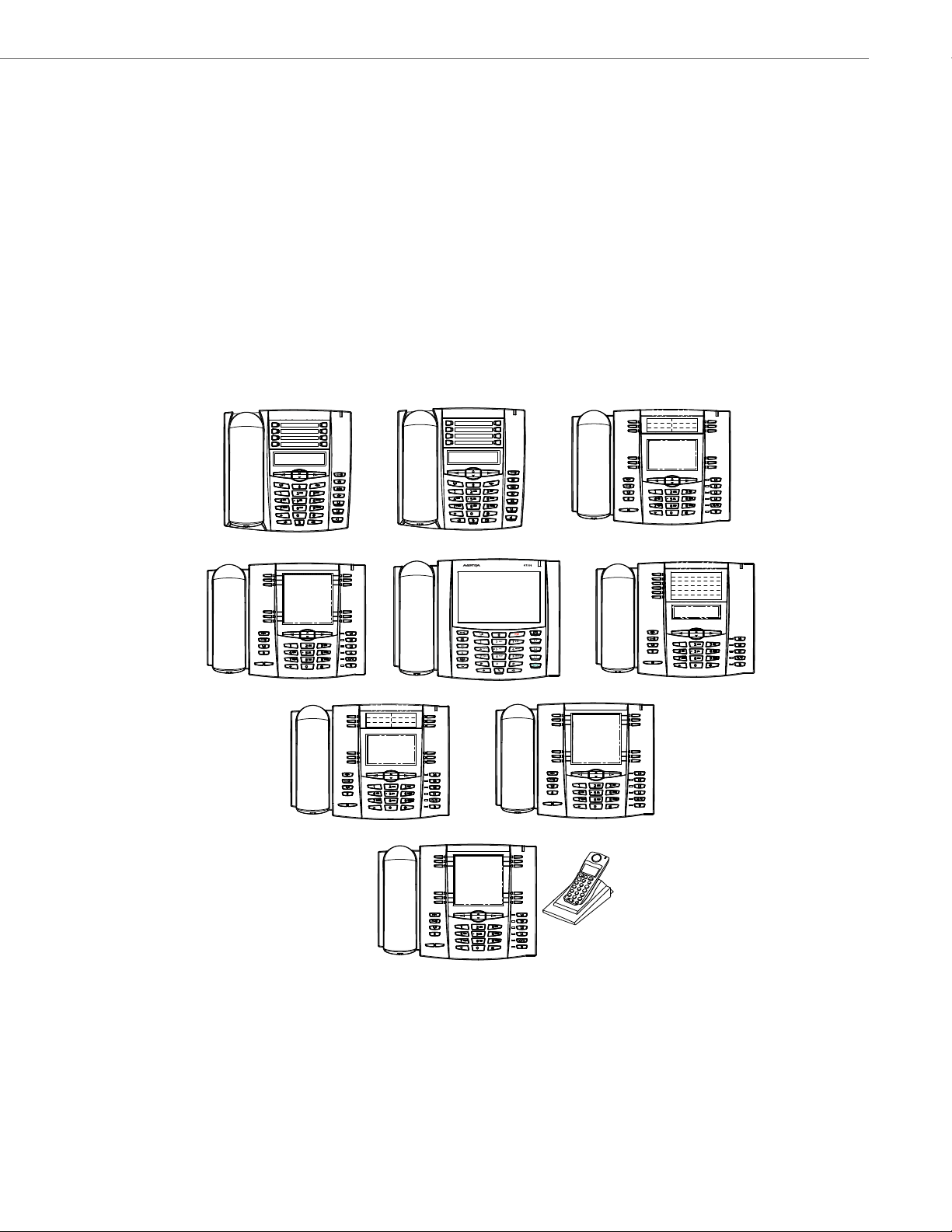
IP Phone Models
6730i
6739i
6755i
6757i
6757i CT
6753i
6731i
6735i
6737i
IP Phone Models
Description
All Aastra SIP IP Phone Models communicate over an IP network allowing you to receive and place calls in the same manner as a regular business telephone.
All phone models support the Session Initiation Protocol (SIP). The 9480i CT and 6757i CT offers the base phone along
with a cordless extension.
References
For more information about the features and installation requirements, see the SIP IP Phone Installation Guide for your
specific model.
The following illustrations show the types of IP Phone Models.
41-001343-02 REV04 – 05.2014 1-2
Page 22
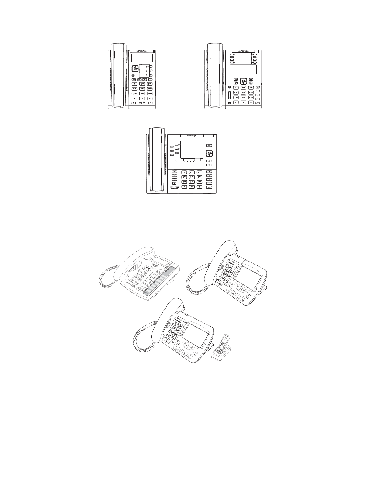
IP Phone Models
6865i
6867i
6863i
9480i
9480i CT
9143i
Hold
Redial
Goodbye
Options
Directory
Save
Conf
Delete
Xfer
L3
L2
L1
Mute
Hold
Redial
Good
bye
Options
Xfer
Conf
9480i CT
Icom
Services
Options
Xfer
Conf
9480i
Icom
Services
1-3 41-001343-02 REV04 – 05.2014
Page 23
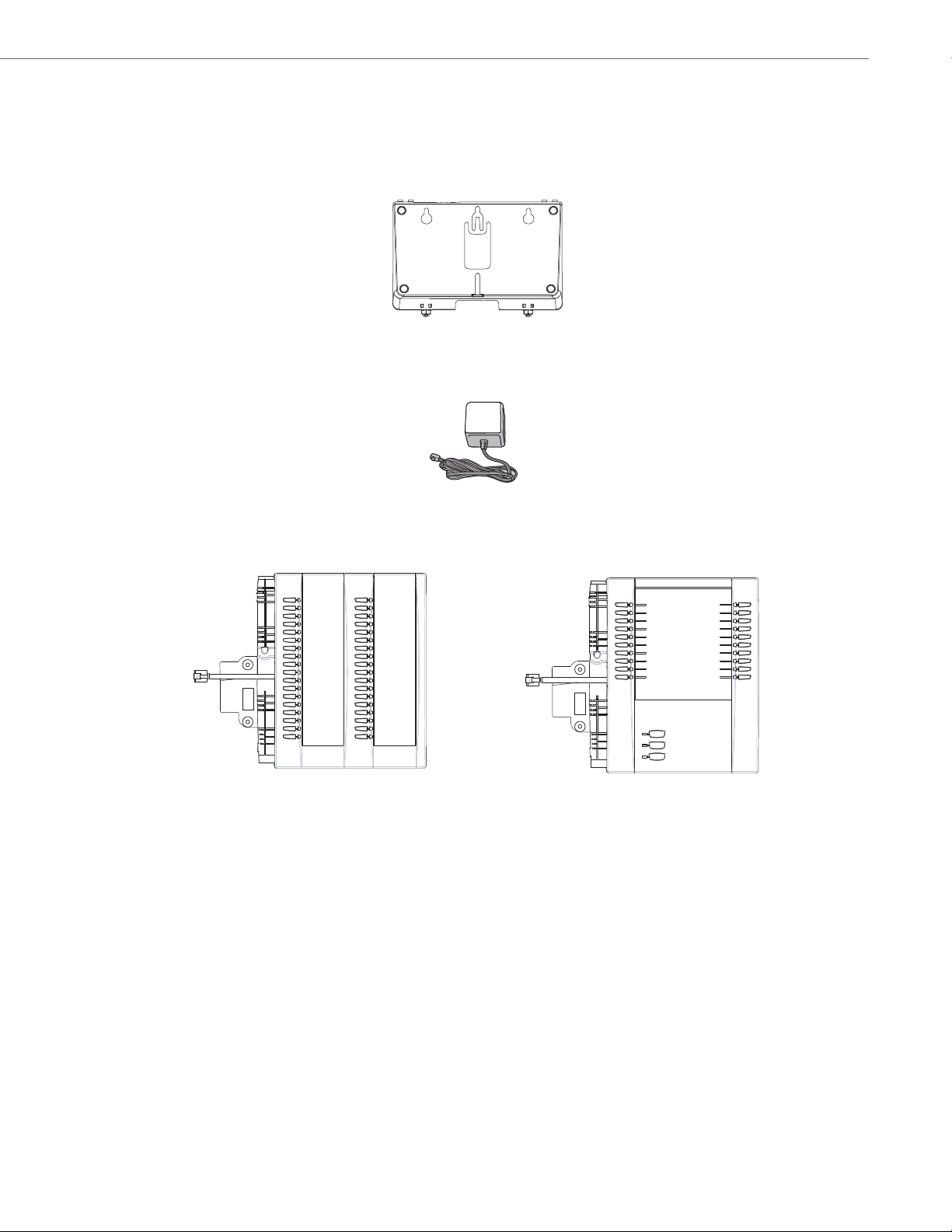
Optional Accessories
6700i Wall Mount Kit
Power Adapter
M670i Expansion Module
for 6735i, 6737i, 6739i, 6753i, 6755i,
M675i Expansion Module
for 6735i, 6737i, 6739i, 6755i, 6757i,
6757i, and 6757i CT
and 6757i CT
6700 Series
The following are optional accessories specifically for the 6700i Series IP Phones.
The following are optional accessories specifically for the 6731i, 6735i, 6737i, and 6739i IP Phones.
IP Phone Models
The following are optional accessories specifically for the 6735i, 6737i, 6739i, 6753i, 6755i, 6757i, and 6757i CT IP Phones.
The M670i module adds 36 additional softkeys to the IP phone models 6735i, 6737i, 6739i, 6753i, 6755i, 6757i, and 6757i
CT. The M670i provides paper labels for each softkey. Up to 3 modules can be daisy-chained to provide up to 108 additional softkeys for the phone when powered via the 48V AC adapter.
The M675i module adds 60 additional softkeys to the IP phone models 6735i, 6737i, 6739i, 6755i, 6757i, and 6757i CT
(using the 3 function keys on the bottom right of the unit). The M675i module provides an LCD screen for displaying
softkey labels. Up to 3 modules can be daisy-chained to provide up to 180 additional softkeys for the phone when powered via the 48V AC adapter.
Refer to the table below for additional daisy-chaining information.
41-001343-02 REV04 – 05.2014 1-4
Page 24

IP Phone Models
M670i/M675i Expansion Modules Daisy-Chaining Support
IP Phone Model
6730i 0 N/A No PoE Support
6731i 0 0 Class 1 (<3.84W)
6735i 3 1 Class 2 (< 6.49W)
6737i 3 1 Class 2 (< 6.49W)
6739i 3 0 Class 0 (< 12.94W)
6753i 3 3 Class 0 (< 12.94W)
6755i 3 3 Class 0 (< 12.94W)
6757i 3 3 Class 0 (< 12.94W)
6757i CT 3 3 Class 0 (< 12.94W)
Maximum Number of Diasy-Chained
Modules When Powered Via 48V AC Adapter
Note:
Daisy-chaining M670i modules with M675i modules is supported for all IP phone models except the 6753i (the 6753i
only supports the M670i expansion module).
Reference
For more information about installing the 6700i Wall Mount Kit and setting up and using the expansion modules, see the
6700i Wall Mount Kit Installation Guide, your <Model-Specific> Installation Guide, as well as your <Model-Specific>
IP Phone User Guide.
Maximum Number of Diasy-Chained
Modules When Powered Via PoE
PoE Class
1-5 41-001343-02 REV04 – 05.2014
Page 25
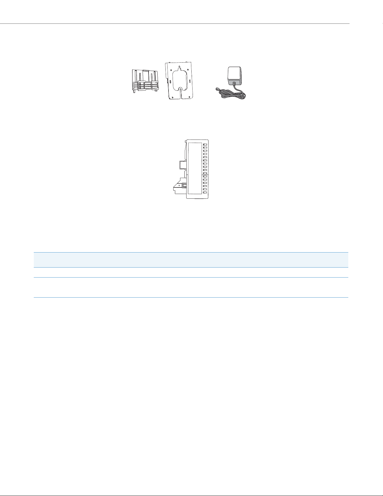
6800i Series
6800i Wall Mount Kit
Power Adapter
M680i Expansion Module
The following are optional accessories specifically for the 6800i Series IP Phones.
The following are optional accessories specifically for the 6865i and 6867i IP Phones.
IP Phone Models
The M680i module adds 16 additional softkeys to the 6865i and 6867i IP phones and provides paper labels for each
softkey. Up to 3 modules can be daisy-chained to provide up to 48 additional softkeys for the phone. No separate power
adaptor is required as the M680i is powered by the respective IP phone.
M680i Expansion Modules Daisy-Chaining Support
IP Phone Model
6865i 3 3 Class 2 (< 6.49W)
6867i 3 3 Class 2 (< 6.49W) without modules.
Maximum Number of Diasy-Chained
Modules When Powered Via 48V AC Adapter
Maximum Number of Diasy-Chained
Modules When Powered Via PoE
PoE Class
Dynamically switches to Class 3
(< 12.95W) when modules are attached.
M680i Software Upgrades
The M680i does not require a separate firmware package. M680i software is embedded within the respective phone’s
firmware package.
When the M680i is connected and is powered up, the LED corresponding to the second button on the module will turn
solid red and the module will check to see if an upgrade is required. If it does not have the latest software, the module will
upgrade itself using the phone’s embedded firmware. This process will take approximately 10 seconds, in which case the
LED corresponding to the second button on the M680i will stay solid red for the duration. If the upgrade is successful, the
LED will turn green. If the LED stays solid and red for longer than 10 seconds, the upgrade may have failed. In such scenarios, unplug and reattach the power source from the phone to attempt the upgrade again.
As software upgrades are performed one at a time, each additional M680i connected increases the approximate upgrade
time by 10 seconds (e.g. three connected M680i expansion modules will take approximately 30 seconds to upgrade).
Reference
For more information about installing the 6800i Wall Mount Kit and setting up and using the M680i expansion module, see
the 6800i Wall Mount Kit Installation Guide, the M680i Expansion Module Installation Guide, M680i Expansion
Module Quick Start Guide, your <Model-Specific> Installation Guide, as well as your <Model-Specific> IP Phone User
Guide.
41-001343-02 REV04 – 05.2014 1-6
Page 26
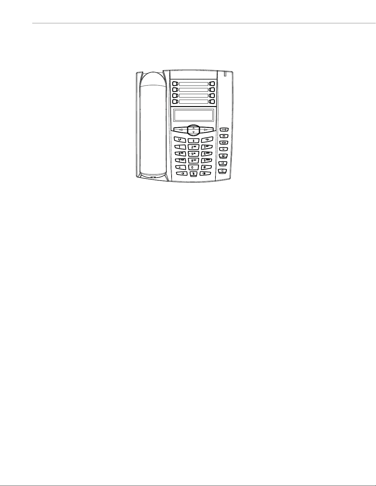
IP Phone Models
6730i with Symbol or Text Keys
Model 6730i IP Phone
This section provides brief information about the Model 6730i IP Phone. It includes a list of features and describes the
hard keys on the 6730i. The 6730i is available with a symbol keypad or a text keypad.
6730i Phone Features (Symbol and Text)
• 3-line LCD screen
• 8 programmable top keys
• Press-and-hold speed dial key configuration feature
• Supports up to 6 call lines with LEDs
• Full-duplex speakerphone for handsfree calls
• Headset mode support (via handset jack)
• AC power adapter (included)
• Enhanced busy lamp fields*
• Set paging*
*Availability of feature dependant on your phone system or service provider.
1-7 41-001343-02 REV04 – 05.2014
Page 27
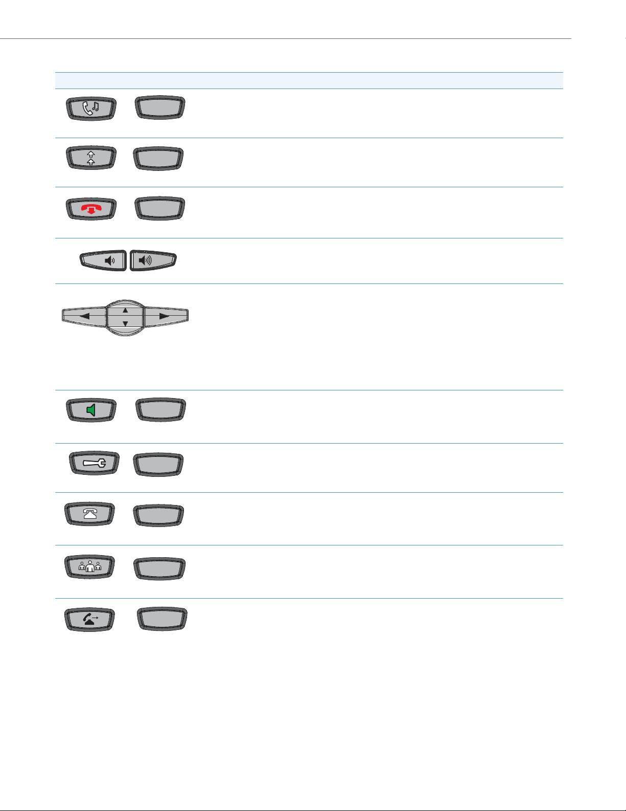
6730i Symbol and Text Key Descriptions*
Redial
Goodbye
Speaker
OptionsOptions
Conf
Symbol Keys Tex t Keys Key Description
Hold key - Places an active call on hold. To retrieve a held call, press the call appearance button beside the
Hold
light that is flashing.
Redial key - Redials up to 100 previously dialed numbers. Pressing the Redial key twice redials the last dialed
number.
Goodbye key - Ends an active call. The Goodbye key also exits an open list, such as the Options List, without
saving changes.
Volume control key - Adjusts the volume for the handset, ringer, and handsfree speaker.
Navigation keys - Pressing the UP and DOWN arrow keys lets you view different status and text messages on
the LCD display (if there is more than 1 line of status/text messages). These keys also let you scroll through
menu selections, such as the Options List, and scroll through a remote number that is displayed on the
phone. Users can press the scrolling DOWN navigation key to view the rest of the phone number content.
IP Phone Models
Callers
Transfer
Pressing the LEFT and RIGHT arrow keys lets you view the different line/call appearances. While in the Options
List, these keys allow you to exit or enter the current option.
When you are editing entries on the display, pressing the LEFT arrow key works as a backspace instead of a
moving cursor. the LEFT arrow key erases the digit/character at the cursor location including the dot/decimal.
The RIGHT arrow key sets the option.
Speaker key - Transfers the active call to the speaker, allowing handsfree use of the phone. Switched
between headset and speaker depending on audio mode setting.
Options key - Accesses services and options to customize your phone. Your System Administrator may have
already customized some of your settings.
Callers List key - Accesses the last 200 calls received.
Conference key - Begins a conference call with the active call.
Transfer key - Transfers the active call to another number.
41-001343-02 REV04 – 05.2014 1-8
Page 28

IP Phone Models
Line 1Line 1
Line 2Line 2
1
2
3
4
5
6
7
8
Symbol Keys Tex t Keys Key Description
Line/Call Appearance keys - Connect you to a line or call. The Aastra 6730i IP phone supports 2 line keys,
each with LED indicator lights. Additional lines (up to 6 in total) can be added to the programmable keys.
Programmable keys - 8 Top Keys - all 8 keys are programmable.
Keys 5 and 6 are designated as the SAVE and DELETE keys, respectively. These keys must be made configura-
ble by the System Administrator before they can be changed.
The following are the default functions for the programmable keys on the 6730i IP phone:
1 - None
2 - None
3 - None
4 - None
5 - SAVE - Allows you to save numbers (preconfigured) and/or names to the Directory. Using this key, you
enter the number, name, and line (or speed dial key) to record in the Directory List.
6 - DELETE - Allows you to delete entries (preconfigured) from the Directory List and Callers List. (Must enter
the Directory or Callers list and select an entry, then press twice to delete entry).
7 - DIRECTORY - Displays up to 200 names (preconfigured) and phone numbers (stored in alphabetical order)
8 - SERVICES - Accesses enhanced features (preconfigured) and services through the Services menu.
Note:
For more information about configuring the programmable keys 1 through 8 to perform specific functions,
see Chapter 5, “Configuring Operational Features” the section, “Softkeys/Programmable Keys/Feature
Keys/Expansion Module Keys” on page5-104.
*See the Aastra Model 6730i IP Phone User Guide for more information about each of these keys.
1-9 41-001343-02 REV04 – 05.2014
Page 29

IP Phone Models
6731i with Symbol or Text Keys
Model 6731i IP Phone
This section provides brief information about the Model 6731i IP Phone. It includes a list of features and describes the hard
keys on the 6731i. The 6731i is available with a symbol keypad or a text keypad.
6731i Phone Features (Symbol and Text)
• 3-line LCD screen
• 8 programmable top keys
• Press-and-hold speed dial key configuration feature
• Supports up to 6 call lines with LEDs
• Full-duplex speakerphone for handsfree calls
• Headset mode support (via handset jack)
• Built-in two-port, 10/100 Ethernet ports - lets you share a connection with your computer
• Inline power support (based on 802.3af standard) which eliminates power adapters
• AC power adapter (optional equipment - not included)
• Enhanced busy lamp fields*
• Set paging*
*Availability of feature dependant on your phone system or service provider.
41-001343-02 REV04 – 05.2014 1-10
Page 30
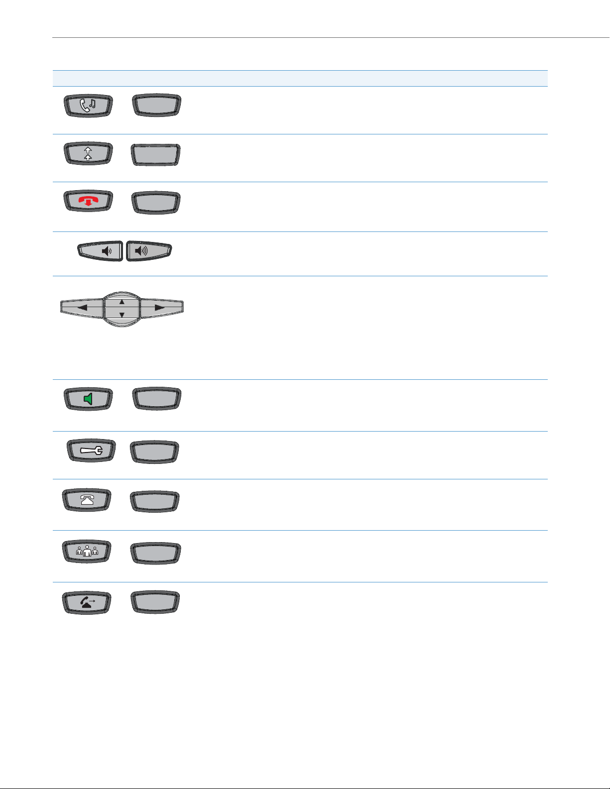
IP Phone Models
Hold
Redial
Goodbye
Speaker
Options
Callers
Conf
Transfer
6731i Symbol and Text Key Descriptions*
Symbol Keys Tex t Keys Key Description
Hold key - Places an active call on hold. To retrieve a held call, press the call appearance button beside the
light that is flashing.
Redial key - Re dia ls up to 1 00 pr evi ousl y di aled num bers . Pressing the Redial key twice redials the last dialed
Redial
number.
Goodbye key - Ends an active call. The Goodbye key also exits an open list, such as the Options List, without
saving changes.
Volume control key - Adjusts the volume for the handset, ringer, and handsfree speaker.
Navigation keys - Pressing the UP and DOWN arrow keys lets you view different status and text messages on
the LCD display (if there is more than 1 line of status/text messages). These keys also let you scroll through
menu selections, such as the Options List, and scroll through a remote number that is displayed on the
phone. Users can press the scrolling DOWN navigation key to view the rest of the phone number content.
Options
Pressing the LEFT and RIGHT arrow keys lets you view the different line/call appearances. While in the
Options List, these keys allow you to exit or enter the current option.
When you are editing entries on the display, pressing the LEFT arrow key works as a backspace instead of a
moving cursor. the LEFT arrow key erases the digit/character at the cursor location including the dot/decimal. The RIGHT arrow key sets the option.
Speaker key - Transfers the active call to the speaker, allowing handsfree use of the phone. Switched
between headset and speaker depending on audio mode setting.
Options key - Accesses services and options to customize your phone. Your System Administrator may have
already customized some of your settings.
Callers List key - Accesses the last 200 calls received.
Conference key - Begins a conference call with the active call.
Transfer key - Transfers the active call to another number.
1-11 41-001343-02 REV04 – 05.2014
Page 31

Symbol Keys Tex t Keys Key Description
Line 1Line 1
Line 2Line 2
1
2
3
4
5
6
7
8
Line/Call Appearance keys - Connect you to a line or call. The Aastra 6731i IP phone supports 2 line keys,
each with LED indicator lights. Additional lines (up to 6 in total) can be added to the programmable keys.
Programmable keys - 8 Top Keys - all 8 keys are programmable.
Keys 5 and 6 are designated as the SAVE and DELETE keys, respectively. These keys must be made configura-
ble by the System Administrator before they can be changed.
The following are the default functions for the programmable keys on the 6731i IP phone:
1 - None
2 - None
3 - None
4 - None
5 - SAVE - Allows you to save numbers (preconfigured) and/or names to the Directory. Using this key, you
enter the number, name, and line (or speed dial key) to record in the Directory List.
6 - DELETE - Allows you to delete entries (preconfigured) from the Directory List and Callers List. (Must enter
the Directory or Callers list and select an entry, then press twice to delete entry).
7 - DIRECTORY - Displays up to 200 names (preconfigured) and phone numbers (stored in alphabetical
order)
8 - SERVICES - Accesses enhanced features (preconfigured) and services through the Services menu.
IP Phone Models
Note:
For more information about configuring the programmable keys 1 through 8 to perform specific functions,
see Chapter 5, “Configuring Operational Features” the section, “Softkeys/Programmable Keys/Feature
Keys/Expansion Module Keys” on page5-104.
*See the Aastra Model 6731i IP Phone User Guide for more information about each of these keys.
41-001343-02 REV04 – 05.2014 1-12
Page 32

IP Phone Models
6735i with Symbol or Text Keys
Model 6735i IP Phone
This section provides brief information about the Model 6735i IP Phone. It includes a list of features, and describes the
hard keys, default programmable keys, and default softkeys on the 6735i. The 6735i is available with a symbol keypad or
a text keypad.
6735i Phone Features (Symbol and Text)
• 8-line graphical LCD screen (144 x 75 pixels) with white backlight
• 12 programmable keys
– 6 programmable hard keys on the top
– 6 programmable state-based softkeys on the bottom
• 4 call appearance lines with LEDs
• Press-and-Hold speed dial key configuration feature
• Supports up to 9 call lines
• Full-duplex speakerphone for handsfree calls
• Headset support (modular connector)
• Built-in-two-port, 10/100/1000 Ethernet switch - lets you share a connection with your computer.
• Inline power support (based on 802.3af standard) which eliminates power adapters.
• Enhanced busy lamp fields*
• Set paging*
*Availability of feature dependant on your phone system or service provider.
1-13 41-001343-02 REV04 – 05.2014
Page 33

6735i Symbol and Text Key Descriptions*
Goodbye
OptionsOptions
Hold
Redial
L1L1
L2L2
L3L3
L4L4
Line 1
Line 2
Line 3
Line 4
Mute
Symbol Keys Tex t Keys Key Description
Goodbye key - Ends an active call. The Goodbye key also exits an open list, such as the Options List, without
saving changes.
Options key - Accesses options to customize your phone. Your System Administrator may have already customized some of your settings. Check with your System Administrator before changing the administratoronly options.
Hold key - Places an active call on hold. To retrieve a held call, press the call appearance button beside the
light that is flashing.
Redial key - Redials up to 100 previously dialed numbers. Pressing the Redial key twice simultaneously redials the last dialed number.
Volu me con trol key - Adjusts the volume for the handset, headset, ringer, and handsfree speaker.
IP Phone Models
Line 4
Line 3
Line 2
Line 1
Speaker/
Headset
Line/Call Appearance key - Connects you to a line or call. The Aastra 6735i IP phone supports up to 4 line
keys.
Handsfree key - Activates Handsfree for making and receiving calls without lifting the handset. When the
audio mode option is set, this key is used to switch between a headset and the handsfree speakerphone.
Mute key - Mutes the microphone so that your caller cannot hear you (the light indicator flashes when the
microphone is on mute).
Navigation keys - Pressing the UP and DOWN arrow keys lets you view different status and text messages
on the LCD display (if there is more than 1 line of status/text messages). These keys also let you scroll
through menu selections, such as the Options List, and scroll through a remote number that is displayed on
the phone. Users can press the scrolling DOWN navigation key to view the rest of the phone number content.
Pressing the LEFT and RIGHT arrow keys lets you view the different line/call appearances. While in the
Options List, these keys allow you to exit or enter the current option. When you are editing entries on the display, pressing the LEFT arrow key erases the character on the left; pressing the RIGHT arrow key sets the
option.
41-001343-02 REV04 – 05.2014 1-14
Page 34

IP Phone Models
Symbol Keys Tex t Keys Key Description
Programmable keys - 6 Top keys: programmable hard keys (up to 6 programmable functions)
By default, the top keys 1 through 4 are assigned as Services, Directory, Callers List, and Intercom, respectively. Keys 5 and 6 have no assigned functions. All 6 keys are programmable and can be assigned to perform
specific functions.
The following are the default functions for the programmable keys on the 6735i IP phone:
1 - SERVICES -Accesses enhanced features and services such as XML applications and voicemail, provided
by third parties.
2 - DIRECTORY- Displays up to 200 names and phone numbers (stored in alphabetical order).
3 - CALLERS LIST - Accesses the last 200 calls received.
4 - ICOM - Accesses another extension on the network.
5 - None
6 - None
Note:
For more information about configuring the programmable keys 1 through 6 to perform specific functions,
see Chapter 5, “Configuring Operational Features” the section, “Softkeys/Programmable Keys/Feature
Keys/Expansion Module Keys” on page5-104.
Softkeys - 6 Bottom keys: programmable state-based softkeys (up to 20 programmable functions).
By default, the bottom softkeys 2 through 6 have no assigned functions. You can configure all 6 bottom
softkeys to perform specific functions on the 6735i IP phone. However, after you lift the handset, there are
specific static softkeys that display that cannot be changed. These are as follows:
1 - DIAL - Allows you to dial out on the phone.
2 - CONF - Begins a conference call with the active phone.
3 - XFER - Transfers the active call to another number.
Note:
For more information about configuring softkeys 1 through 6 to perform specific functions, see Chapter 5,
“Configuring Operational Features” the section, “Softkeys/Programmable Keys/Feature Keys/Expansion
Module Keys” on page5-104.
*See the Aastra Model 6735i IP Phone User Guide for more information about each of these keys.
1-15 41-001343-02 REV04 – 05.2014
Page 35

IP Phone Models
6737i with Symbol or Text Keys
Model 6737i IP Phone
This section provides brief information about the 6737i IP Phone. It includes a list of features, and describes the hard keys
and default softkeys on the 6737i. The 6737i is available with a symbol keypad or a text keypad.
6737i Phone Features (Symbol and Text)
• 11-line graphical LCD screen (144 x 128 pixels) with white backlight
• 12 multi-functional softkeys
– 6 Top Keys: programmable static softkeys
– 6 Bottom Keys: programmable state-based softkeys
• 4 call appearance lines with LEDs
• Press-and-Hold speed dial key configuration feature
• Supports up to 9 call lines
• Full-duplex speakerphone for handsfree calls
• Headset support (modular connector)
• Built-in-two-port, 10/100/1000 Ethernet switch - lets you share a connection with your computer.
• Inline power support (based on 802.3af standard) which eliminates power adapters.
• Enhanced busy lamp fields*
• Set paging*
*Availability of feature dependant on your phone system or service provider.
41-001343-02 REV04 – 05.2014 1-16
Page 36

IP Phone Models
Goodbye
OptionsOptions
Hold
Redial
L1L1
L2L2
L3L3
L4L4
Line 1
Line 2
Line 3
Line 4
Speaker/
Headset
Mute
6737i Symbol and Text Key Descriptions*
Symbol Keys Text Ke ys Key Description
Goodbye key - Ends an active call. The Goodbye key also exits an open list, such as the Options List, without
saving changes.
Options key - Accesses options to customize your phone. Your System Administrator may have already customized some of your settings. Check with your System Administrator before changing the administratoronly options.
Hold key - Places an active call on hold. To retrieve a held call, press the call appearance button beside the
light that is flashing.
Redial key - Redials up to 100 previously dialed numbers. Pressing the Redial key twice simultaneously redials
the last dialed number.
Volu me control key - Adjusts the volume for the handset, headset, ringer, and handsfree speaker.
Line 4
Line 3
Line 2
Line 1
Line/Call Appearance key - Connects you to a line or call. The Aastra 6737i IP phone supports up to 4 line
keys.
Handsfree key - Activates Handsfree for making and receiving calls without lifting the handset. When the
audio mode option is set, this key is used to switch between a headset and the handsfree speakerphone.
Mute key - Mutes the microphone so that your caller cannot hear you (the light indicator flashes when the
microphone is on mute).
1-17 41-001343-02 REV04 – 05.2014
Page 37

Symbol Keys Te xt Ke ys Key Description
Navigation keys - Pressing the UP and DOWN arrow keys lets you view different status and text messages on
the LCD display (if there is more than 1 line of status/text messages). These keys also let you scroll through
menu selections, such as the Options List, and scroll through a remote number that is displayed on the phone.
Users can press the scrolling DOWN navigation key to view the rest of the phone number content.
Pressing the LEFT and RIGHT arrow keys lets you view the different line/call appearances. While in the Options
List, these keys allow you to exit or enter the current option. When you are editing entries on the display,
pressing the LEFT arrow key erases the character on the left; pressing the RIGHT arrow key sets the option.
Softkeys - 12 softkeys on the 6737i IP Phone.
• 6 Top Keys: programmable static softkeys (up to 10 programmable functions)
• 6 Bottom Keys: programmable state-based softkeys (up to 20 programmable functions)
By default, the top softkeys 1 through 4 are assigned as Services, Directory, Callers List, and Intercom, respectively. Keys 5 and 6 have no assigned functions. All 6 keys are programmable and can be assigned to perform
specific functions.
The following are the default functions for the top softkeys on the 6737i IP phone:
1 - SERVICES - Accesses enhanced features and services such as XML applications and voicemail, provided by
third parties.
2 - DIRECTORY - Displays up to 200 names and phone numbers (stored in alphabetical order).
3 - CALLERS LIST - Accesses the last 200 calls received.
4 - ICOM - Accesses another extension on the network.
5 - None
6 - None
7 - None
IP Phone Models
By default, the bottom softkeys 8 through 12 have no assigned functions. You can configure all 6 bottom
softkeys to perform specific functions on the 6737i IP phone. However, after you lift the handset, there are
specific static softkeys that display that cannot be changed. These are as follows:
7- DIAL - Allows you to dial out on the phone.
8- CONF - Begins a conference call with the active phone.
9- XFER - Transfers the active call to another number.
Note:
For more information about programming the softkeys to perform specific functions, see Chapter 5, “Config-
uring Operational Features” the section, “Softkeys/Programmable Keys/Feature Keys/Expansion Module
Keys” on page5-104.
*See the Aastra Model 6737i IP Phone User Guide for more information about each of these keys.
41-001343-02 REV04 – 05.2014 1-18
Page 38

IP Phone Models
6739i with Symbol or Text Keys
Model 6739i IP Phone
This section provides brief information about the Model 6391i IP Phone. It includes a list of features and describes the
hard keys on the 6739i. The 6739i is available with a symbol keypad or a text keypad.
6739i Phone Features (Symbol and Text)
• Large 5.7” full VGA (640x480) color touch screen display and backlight
• Advanced and expandable Executive Level SIP Phone
• Intuitive graphical user interface and navigation menus
• Two built-in 10/100/1000 Gigabit Ethernet switch ports - lets you share a connection with your computer.
• Inline power support (based on 802.3af Power-over-Ethernet (PoE) standard) which eliminates power adapters
• Built-in Bluetooth technology for headset support
• Existing 675xi Expansion Module support
• USB port support (for future use)
• Aastra Hi-Q Audio™ Technology
• Full-duplex speakerphone for handsfree calls
• Additional headset connection options: modular RJ jack, built-in EHS/DHSG port (refer to the IP Phone 6739i Installa-
tion Guide for information on installing a DHSG headset on your phone.)
• Up to 9 lines with 3 call appearance lines with multi-proxy support
• Up to 55 programmable softkeys
• Picture ID feature (during calls and in the Directory, Callers List, and Redial List)
• XML support for productivity-enhancing applications
• AC power adapter (sold separately)
1-19 41-001343-02 REV04 – 05.2014
Page 39

IP Phone Models
Options
Callers
Directory
Services
Conf
Transfer
Hold
Redial
GoodbyeGoodbye
Messages
6739i Symbol and Text Key Descriptions*
The following table identifies the keys on the key panel of your 6739i IP phone that you can use for handling calls. Your
phone may contain symbol keys or text keys, depending on which Model 6739i phone you purchased.
Symbol Keys Text K eys Key Description
Options Key - Accesses options to customize your phone. Your System Administrator may have already cus-
Options
Callers
Directory
Services
Conf
tomized some of your settings. Check with your System Administrator before changing the administratoronly options.
Callers List Key - Accesses a list of calls received by the phone.
Directory Key - Accesses a directory of names and phone numbers (stored in alphabetical order).
Services Key - Accesses enhanced features and services set up by your System Administrator.
Conference Key - Begins a conference call with the active call.
Transfer
Hold
Messages
Transfer Key - Transfers the active call to another number.
Hold Key - Places an active call on hold. To retrieve a held call, press the call appearance button beside the
light that is flashing or press the Hold key again.
Redial Key - Redials previously dialed numbers. Also accesses a Redial List of up to 100 stored numbers that
called your phone.
Goodbye Key - Ends an active call. The Goodbye key also exits an open list, such as the Options List.
Messages Key - Accesses your phone’s voice mailbox to retrieve and listen to stored messages.
41-001343-02 REV04 – 05.2014 1-20
Page 40

IP Phone Models
Line 1
Line 2
Line 3
Speaker/Speaker/
HeadsetHeadset
MuteMute
Symbol Keys Text Key s Key Description
Line/Call Appearance Keys - Connect you to a line or call. The Aastra 6739i IP phone supports 3 line call
Line 3
Line 2
Line 1
appearance keys.
Speakerphone/Headset Key - Activates handsfree for mak ing and receiving calls without lifting the handset.
When the audio mode option is set, this key is used to switch between a headset and the handsfree speakerphone.
Volume Control Key - Adjusts the volume for the handset, headset, ringer, and handsfree speaker.
Mute key - Mutes the microphone so that your caller cannot hear you (the light indicator flashes when the
microphone is on mute).
*See the Aastra Model 6739i IP Phone User Guide for more information about each of these keys.
1-21 41-001343-02 REV04 – 05.2014
Page 41

IP Phone Models
6753i with Symbol or Text Keys
Model 6753i IP Phone
This section provides brief information about the Model 6753i IP Phone. It includes a list of features, and describes the
hard keys and default programmable keys on the 6753i. The 6753i is available with a symbol keypad or a text keypad.
6753i Phone Features (Symbol and Text)
• 3-line LCD screen
• 6 programmable top keys
• 3 call appearance lines with LEDs
• Press-and-Hold speed dial key configuration feature
• Supports up to 9 call lines
• Full-duplex speakerphone for handsfree calls
• Headset support (modular connector)
• Built-in two-port, 10/100 Ethernet ports - lets you share a connection with your computer
• Inline power support (based on 802.3af standard) which eliminates power adapters.
• AC power adapter (included)
• Enhanced busy lamp fields*
• Set paging*
*Availability of feature dependant on your phone system or service provider.
41-001343-02 REV04 – 05.2014 1-22
Page 42

IP Phone Models
Goodbye
OptionsOptions
Hold
L1L1
L2L2
L3L3
Line 1
Line 2
Line 3
Mute
6753i Symbol and Text Key Descriptions*
Symbol Keys Tex t Keys Key Description
Goodbye key - Ends an active call. The Goodbye key also exits an open list, such as the Options List, without
saving changes.
Options key - Accesses options to customize your phone. Your System Administrator may have already customized some of your settings. Check with your System Administrator before changing the administratoronly options.
Hold key - Places an active call on hold. To retrieve a held call, press the call appearance button beside the
light that is flashing.
Redial key - Re dial s up to 10 0 pre vious ly di aled numbers . Pressing the Redial key twice simultaneously redi-
Redial
als the last dialed number.
Volu me con trol key - Adjusts the volume for the handset, headset, ringer, and handsfree speaker.
Line 3
Line 2
Line 1
Speaker
Line/Call Appearance key - Connects you to a line or call. The Aastra 6753i IP phone supports up to 3 line
keys.
Handsfree key - Activates Handsfree for making and receiving calls without lifting the handset. When the
audio mode option is set, this key is used to switch between a headset and the handsfree speakerphone.
Mute key - Mutes the microphone so that your caller cannot hear you (the light indicator flashes when the
microphone is on mute).
1-23 41-001343-02 REV04 – 05.2014
Page 43

Symbol Keys Tex t Ke ys Key Description
Navigation keys - Pressing the UP and DOWN arrow keys lets you view different status and text messages
on the LCD display (if there is more than 1 line of status/text messages). These keys also let you scroll through
menu selections, such as the Options List, and scroll through a remote number that is displayed on the
phone. Users can press the scrolling DOWN navigation key to view the rest of the phone number content.
Pressing the LEFT and RIGHT arrow keys lets you view the different line/call appearances. While in the
Options List, these keys allow you to exit or enter the current option.
When you are editing entries on the display, pressing the LEFT arrow key works as a backspace instead of a
moving cursor. the LEFT arrow key erases the digit/character at the cursor location including the dot/decimal. The RIGHT arrow key sets the option.
Programmable keys - 6 Top Keys - all 6 keys are programmable.
Keys 1 and 2 are designated as the SAVE and DELETE keys, respectively. These keys are locked but can be
unlocked and made configurable if required by the System Administrator.
The following are the default functions for the programmable keys on the 6753i IP phone:
1 - SAVE - Allows you to save numbers and/or names to theDirectory. Using this key, you enter the number,
name, and line (or speed dial key) to record in the Directory List.
2 - DELETE - Allows you to delete a single entry or all entries fromthe Directory List and Callers List.
3 - DIRECTORY - Displays up to 200 names and phone numbers (stored in alphabetical order).
4 - CALLERS LIST - Accesses the last 200 calls received.
5 - TRANSFER - Transfers the active call to another number.
6 - CONFERENCE - Begins a conference call with the active call.
IP Phone Models
Notes:
• For more information about programming the SAVE and DELETE keys, see “Locking/Unlocking the SAVE
and DELETE keys” on page5-51.
• For more information about configuring keys 1 through 6 to perform specific functions, see Chapter 5,
“Configuring Operational Features” the section, “Softkeys/Programmable Keys/Feature Keys/Expansion
Module Keys” on page5-104.
*See the Aastra Model 6753i IP Phone User Guide for more information about each of these keys.
41-001343-02 REV04 – 05.2014 1-24
Page 44

IP Phone Models
6755i with Symbol or Text Keys
Model 6755i IP Phone
This section provides brief information about the Model 6755i IP Phone. It includes a list of features, and describes the
hard keys, default programmable keys, and default softkeys on the 6755i. The 6755i is available with a symbol keypad or
a text keypad.
6755i Phone Features (Symbol and Text)
• 8-line graphical LCD screen (144 x 75 pixels) with white backlight
• 12 programmable keys
– 6 programmable hard keys on the top
– 6 programmable state-based softkeys on the bottom
• 4 call appearance lines with LEDs
• Press-and-Hold speed dial key configuration feature
• Supports up to 9 call lines
• Full-duplex speakerphone for handsfree calls
• Headset support (modular connector)
• Built-in-two-port, 10/100 Ethernet switch - lets you share a connection with your computer.
• Inline power support (based on 802.3af standard) which eliminates power adapters.
• AC power adapter (included)
• Enhanced busy lamp fields*
• Set paging*
*Availability of feature dependant on your phone system or service provider.
1-25 41-001343-02 REV04 – 05.2014
Page 45

6755i Symbol and Text Key Descriptions*
Goodbye
OptionsOptions
Hold
Redial
L1
L2
L3
L4
Line 1Line 1
Line 2Line 2
Line 3Line 3
Line 4Line 4
Mute
Symbol Keys Tex t Keys Key Description
Goodbye key - Ends an active call. The Goodbye key also exits an open list, such as the Options List, with-
out saving changes.
Options key - Accesses options to customize your phone. Your System Administrator may have already
customized some of your settings. Check with your System Administrator before changing the administrator-only options.
Hold key - Places an active call on hold. To retrieve a held call, press the call appearance button beside the
light that is flashing.
Redial key - Redials up to 100 previously dialed numbers. Pressing the Redial key twice simultaneously
redials the last dialed number.
Volume control key - Adjusts the volume for the handset, headset, ringer, and handsfree speaker.
IP Phone Models
L4
L3
L2
L1
Speaker/
Headset
Line/Call Appearance key - Connects you to a line or call. The Aastra 6755i IP phone supports up to 4 line
keys.
Handsfree key - Activates Handsfree for making and receiving calls without lifting the handset. When the
audio mode option is set, this key is used to switch between a headset and the handsfree speakerphone.
Mute key - Mutes the microphone so that your caller cannot hear you (the light indicator flashes when the
microphone is on mute).
Navigation keys - Pressing the UP and DOWN arrow keys lets you view different status and text messages
on the LCD display (if there is more than 1 line of status/text messages). These keys also let you scroll
through menu selections, such as the Options List, and scroll through a remote number that is displayed
on the phone. Users can press the scrolling DOWN navigation key to view the rest of the phone number
content.
Pressing the LEFT and RIGHT arrow keys lets you view the different line/call appearances. While in the
Options List, these keys allow you to exit or enter the current option. When you are editing entries on the
display, pressing the LEFT arrow key erases the character on the left; pressing the RIGHT arrow key sets the
option.
41-001343-02 REV04 – 05.2014 1-26
Page 46

IP Phone Models
Symbol Keys Tex t Ke ys Key Description
Programmable keys - 6 Top keys: programmable hard keys (up to 6 programmable functions)
By default, the top keys 1 through 4 are assigned as Services, Directory, Callers List, and Intercom, respectively. Keys 5 and 6 have no assigned functions. All 6 keys are programmable and can be assigned to perform specific functions.
The following are the default functions for the programmable keys on the 6755i IP phone:
1 - SERVICES - Accesses enhanced features and services such as XML applications and voicemail, provided
by third parties.
2 - DIRECTORY - Displays up to 200 names and phone numbers (stored in alphabetical order).
3 - CALLERS LIST - Accesses the last 200 calls received.
4 - ICOM - Accesses another extension on the network.
5 - None
6 - None
Note:
For more information about configuring the programmable keys 1 through 6 to perform specific functions, see Chapter 5, “Configuring Operational Features” the section, “Softkeys/Programmable Keys/Fea-
ture Keys/Expansion Module Keys” on “Softkeys/Programmable Keys/Feature Keys/Expansion Module
Keys”.
Softkeys - 6 Bottom keys: programmable state-based softkeys (up to 20 programmable functions).
By default, the bottom softkeys 2 through 6 have no assigned functions. You can configure all 6 bottom
softkeys to perform specific functions on the 6755i IP phone. However, after you lift the handset, there are
specific static softkeys that display that cannot be changed. These are as follows:
1 - DIAL - Allows you to dial out on the phone.
2 - CONF - Begins a conference call with the active phone.
3 - XFER - Transfers the active call to another number.
Note:
For more information about configuring softkeys 1 through 6 to perform specific functions, see Chapter 5,
“Configuring Operational Features” the section, “Softkeys/Programmable Keys/Feature Keys/Expansion
Module Keys” on page5-104.
*See the Aastra Model 6755i IP Phone User Guide for more information about each of these keys.
1-27 41-001343-02 REV04 – 05.2014
Page 47

IP Phone Models
6757i with Symbol or Text Keys 6757i CTwith Symbol or Text Keys
Model 6757i and 6757i CT IP Phones
This section provides brief information about the 6757i IP Phone. It includes a list of features, and describes the hard keys
and default softkeys on the 6757i. The 6757i is available with a symbol keypad or a text keypad.
6757i and 6757i CT Phone Features (Symbol and Text)
• 11-line graphical LCD screen (144 x 128 pixels) with white backlight
• 12 multi-functional softkeys
– 6 Top Keys: programmable static softkeys
– 6 Bottom Keys: programmable state-based softkeys
• 4 call appearance lines with LEDs
• Press-and-Hold speed dial key configuration feature
• Supports up to 9 call lines
• Full-duplex speakerphone for handsfree calls
• Headset support (modular connector)
• Built-in-two-port, 10/100 Ethernet switch - lets you share a connection with your computer.
• Inline power support (based on 802.3af standard) which eliminates power adapters.
• AC power adapter (included)
• Enhanced busy lamp fields*
• Set paging*
*Availability of feature dependant on your phone system or service provider.
41-001343-02 REV04 – 05.2014 1-28
Page 48

IP Phone Models
Goodbye
OptionsOptions
Hold
Redial
L1L1
L2L2
L3L3
L4L4
Line 1
Line 2
Line 3
Line 4
Speaker/
Headset
Mute
6757i and 6757i CT Symbol and Text Key Descriptions*
Symbol Keys Tex t Ke ys Key Description
Goodbye key - Ends an active call. The Goodbye key also exits an open list, such as the Options List, with-
out saving changes.
Options key - Accesses options to customize your phone. Your System Administrator may have already
customized some of your settings. Check with your System Administrator before changing the administrator-only options.
Hold key - Places an active call on hold. To retrieve a held call, press the call appearance button beside the
light that is flashing.
Redial key - Redials up to 100 previously dialed numbers. Pressing the Redial key twice simultaneously
redials the last dialed number.
Volume control key - Adjusts the volume for the handset, headset, ringer, and handsfree speaker.
Line 4
Line 3
Line 2
Line 1
Line/Call Appearance key - C onne cts you t o a l ine o r ca ll. T he A astr a 67 57i I P ph one s upp ort s up t o 4 l ine
keys.
Handsfree key - Activates Handsfree for making and receiving calls without lifting the handset. When the
audio mode option is set, this key is used to switch between a headset and the handsfree speakerphone.
Mute key - Mutes the microphone so that your caller cannot hear you (the light indicator flashes when the
microphone is on mute).
1-29 41-001343-02 REV04 – 05.2014
Page 49

Symbol Keys Tex t Keys Key Description
Navigation keys - Pressing the UP and DOWN arrow keys lets you view different status and text messages
on the LCD display (if there is more than 1 line of status/text messages). These keys also let you scroll
through menu selections, such as the Options List, and scroll through a remote number that is displayed
on the phone. Users can press the scrolling DOWN navigation key to view the rest of the phone number
content.
Pressing the LEFT and RIGHT arrow keys lets you view the different line/call appearances. While in the
Options List, these keys allow you to exit or enter the current option. When you are editing entries on the
display, pressing the LEFT arrow key erases the character on the left; pressing the RIGHT arrow key sets the
option.
Softkeys - 12 softkeys on the 6757i IP Phone.
• 6 Top Keys: programmable static softkeys (up to 10 programmable functions)
• 6 Bottom Keys: programmable state-based softkeys (up to 20 programmable functions)
By default, the top softkeys 1 through 4 are assigned as Services, Directory, Callers List, and Intercom,
respectively. Keys 5 and 6 have no assigned functions. All 6 keys are programmable and can be assigned
to perform specific functions.
The following are the default functions for the top softkeys on the 6757i IP phone:
1 - SERVICES - Accesses enhanced features and services such as XML applications and voicemail, provided by third parties.
2 - DIRECTORY - Displays up to 200 names and phone numbers (stored in alphabetical order).
3 - CALLERS LIST - Accesses the last 200 calls received.
4 - ICOM - Accesses another extension on the network.
5 - None
6 - None
7 - None
IP Phone Models
By default, the bottom softkeys 8 through 12 have no assigned functions. You can configure all 6 bottom
softkeys to perform specific functions on the 6757i IP phone. However, after you lift the handset, there are
specific static softkeys that display that cannot be changed. These are as follows:
7- DIAL - Allows you to dial out on the phone.
8- CONF - Begins a conference call with the active phone.
9- XFERT - ransfers the active call to another number.
Note:
For more information about programming the softkeys to perform specific functions, see Chapter 5, “Con-
figuring Operational Features” the section, “Softkeys/Programmable Keys/Feature Keys/Expansion Module Keys” on page5-104.
*See the Aastra Model 6757i or 6757i CT IP Phone User Guide for more information about each of these keys.
41-001343-02 REV04 – 05.2014 1-30
Page 50

IP Phone Models
1
2
3
4
5
6
7
8
15
9
10
5
11
12
13
15
14
16
6757i CT Cordless Handset Features
• 5-line backlit display screen
• 2 multi-functional softkeys
• Programmable function key supports up to 14 functions
• Vibration Alerter
• Headset Jack
• Desk charging stand
1-31 41-001343-02 REV04 – 05.2014
Page 51

6757i CT Cordless Handset Key Descriptions
Function # Function Description
1 Receiver
2 Volume key
During Ringing: Adjusts ringer volume
During a call: Adjusts receiver volume
During text mode (not in a call): Moves cursor right/left
3 Display
4 Features ƒ Key List
Access key to the programmed Feature Key List
Scrolls up when in the various lists
Adds a space during editing
5 Softkeys
Activates feature or option shown on the display above the keys
6 Call key
Used to obtain dial tone
Also used as a Hold key
7 Dial Pad
8 Mute Key
When used, prevents the caller from hearing you
9 Headset Jack
10 Status Light
11 Release key
To end calls and go on hook
Exits Menu and the various lists
12 Menu Key
Access key to the different Options
Scrolls down when in the various lists
Used as Backspace during editing
13 Redial Key
Displays the last 10 numbers dialed
14 Charging Jack
15 Charging Contacts
16 Microphone
IP Phone Models
41-001343-02 REV04 – 05.2014 1-32
Page 52

IP Phone Models
Model 6863i IP Phone
This section provides brief information about the Model 6863i IP Phone. It includes a list of features and describes the
hard keys on the 6863i.
6863i Phone Features
• LCD screen
• Built-in-two-port, 10/100 Fast Ethernet switch - lets you share a connection with your computer
• 3 programmable keys
• Press-and-hold speeddial key configuration feature
• Supports up to 2 call lines with LEDs
• Wideband handset
• Wideband, full-duplex speakerphone for handsfree calls
• AC power adapter (sold separately)
• Set paging*
*Availability of feature dependant on your phone system or service provider.
1-33 41-001343-02 REV04 – 05.2014
Page 53

6863i Key Description
Key Description
Navigation/Select Keys - Pr ess ing the UP a nd DOW N ke ys l ets you vie w di ffe ren t st atu s an d te xt m es sag es o n th e LCD di spl ay
(if there is more than 1 line of status/text messages). These buttons also let you scroll through menu selections, such as the
Options List.
Pressing the LEFT and RIGHT keys lets you view the different line/call appearances. While in the Options List, these keys allow
you to exit or enter the current option. When you are editing entries on the display, pressing the LEFT key erases the character
on the left; pressing the RIGHT key sets the option. Alternatively, pressing the center Select key sets the option as well on specific screens.
Options Key - Accesses services and options to customize your phone. Your System Administrator may have already customized some of your settings. Check with your System Administrator before changing the administrator-only options.
Goodbye Key - Ends an active call. The Goodbye key also exits an open list, such as the Options List, without saving changes.
Hold Key - Places an active call on hold. To retrieve a held call, press the call appearance button beside the light that is flashing.
Line/Call Appearance Keys - Connects you to a line or call. The Aastra 6730i supports two line keys, each with LED indicator
lights.
IP Phone Models
Mute Key - Mutes the microphone so that your caller cannot hear you (the light indicator flashes when the microphone is on
mute).
Volume Co ntrol s - Adjusts the volume for the handset, ringer, and handsfree speaker.
Speaker Key - Transfers the active call to the speaker, allowing handsfree use of the phone.
Programmable Keys - When programmed, allows you to easily perform up to 3 specific functions (e.g. Services, Directory,
Intercom, etc...) and access enhanced services provided by third parties (e.g. XML applications). The programmable keys are
pre-configured as (from top to bottom) Callers, Redial, and Transfer keys.
41-001343-02 REV04 – 05.2014 1-34
Page 54

IP Phone Models
Model 6865i IP Phone
This section provides brief information about the Model 6865i IP Phone. It includes a list of features and describes the
hard keys on the 6865i.
6865i Phone Features
• LCD screen with backlight
• Built-in-two-port, 10/100/1000 Gigabit Ethernet switch - lets you share a connection with your computer
• 8 programmable top keys
• Press-and-hold speeddial key configuration feature
• Supports up to 9 call lines with LEDs
• Wideband handset
• Wideband, full-duplex speakerphone for handsfree calls
• Headset mode support
• AC power adapter (sold separately)
• Enhanced busy lamp fields*
• Set paging*
*Availability of feature dependant on your phone system or service provider.
1-35 41-001343-02 REV04 – 05.2014
Page 55

6865i Key Description
Key Description
Goodbye Key - Ends an active call. The Goodbye key also exits an open list, such as the Options List, without saving changes.
Hold Key - Places an active call on hold. To retrieve a held call, press the call appearance button beside the light that is flashing.
Navigation/Select Keys - Pr ess ing the UP a nd DOW N ke ys l ets you vie w di ffe ren t st atu s an d te xt m es sag es o n th e LCD di spl ay
(if there is more than 1 line of status/text messages). These buttons also let you scroll through menu selections, such as the
Options List.
Pressing the LEFT and RIGHT keys lets you view the different line/call appearances. While in the Options List, these keys allow
you to exit or enter the current option. When you are editing entries on the display, pressing the LEFT key erases the character
on the left; pressing the RIGHT key sets the option. Alternatively, pressing the center Select key sets the option as well on specific screens.
Transfer Key - Transfers the active call to another number.
Conference Key - Begins a conference call with the active call.
IP Phone Models
Options Key - Accesses services and options to customize your phone. Your System Administrator may have already customized some of your settings. Check with your System Administrator before changing the administrator-only options.
Volume Co ntrol s - Adjusts the volume for the handset, ringer, and handsfree speaker.
Mute Key - Mutes the microphone so that your caller cannot hear you (the light indicator flashes when the microphone is on
mute).
Callers List Key - Accesses a list of the last 200 calls received.
Redial Key - Accesses a list of the last 100 previously dialed numbers. Pressing the Redial key twice redials the last dialed
number.
Line/Call Appearance Keys - Connects you to a line or call. The Aastra 6730i IP Phone supports two line keys, each with LED
indicator lights.
41-001343-02 REV04 – 05.2014 1-36
Page 56

IP Phone Models
Key Description
Speaker/Headset Key - Transfers the active call to the speaker or headset, allowing handsfree use of the phone.
Programmable Keys - When programmed, allows you to easily perform up to 8 specific functions (e.g. Services, Directory,
Callers List, Intercom, etc...) and access enhanced services provided by third parties (e.g. XML applications).
1-37 41-001343-02 REV04 – 05.2014
Page 57

IP Phone Models
Model 6867i IP Phone
This section provides brief information about the Model 6867i IP Phone. It includes a list of features and describes the hard
keys on the 6867i.
6867i Phone Features
• 3.5” QVGA color TFT LCD with backlight
• Built-in-two-port, 10/100/1000 Gigabit Ethernet switch - lets you share a connection with your computer
• USB 2.0 port (100mA maximum)
• 6 programmable and 4 context-sensitive softkeys
• Press-and-hold speeddial key configuration feature
• Supports up to 9 call lines with LEDs
• Wideband handset
• Wideband, full-duplex speakerphone for handsfree calls
• Headset mode support
• AC power adapter (sold separately)
• Enhanced busy lamp fields*
• Set paging*
*Availability of feature dependant on your phone system or service provider.
41-001343-02 REV04 – 05.2014 1-38
Page 58

IP Phone Models
6867i Key Description
Key Description
Goodbye Key - Ends an active call. The Goodbye key also exits an open list, such as the Options List, without saving
changes.
Hold Key - Places an active call on hold. To retrieve a held call, press the call appearance button beside the light that is
flashing.
Options Key - Accesses services and options to customize your phone. Your System Administrator may have already customized some of your settings. Check with your System Administrator before changing the administrator-only options.
Mute Key - Mutes the microphone so that your caller cannot hear you (the light indicator flashes when the microphone
is on mute).
Volu me Controls - Adjusts the volume for the handset, ringer, and handsfree speaker.
Callers List Key - Accesses a list of the last 200 calls received.
Redial Key - Accesses a list of the last 100 previously dialed numbers. Pressing the Redial key twice redials the last dialed
number.
Line/Call Appearance Keys - Connects you to a line or call. The Aastra 6730i IP Phone supports two line keys, each with
LED indicator lights.
Speaker/Headset Key - Transfers the active call to the speaker or headset, allowing handsfree use of the phone.
Directory Key - Accesses a directory of names and phone numbers (stored in alphabetical order).
Navigation/Select Keys - Multi-directional navigation keys allow you to navigate through the phone’s user interface.
Pressing the center Select key selects/sets options and performs various actions (such as dialing out when in the Directory, Callers, and Redial Lists).
Transfer Key - Transfers the active call to another number.
Conference Key - Begins a conference call with the active call.
1-39 41-001343-02 REV04 – 05.2014
Page 59

Key Description
Presence Key - Accesses the partial and full contact presence information screens, which provide more detailed infor-
mation about the selected contact.
Left Softkeys - 6 programable keys that allow you to easily perform up to 20 specific functions and access enhanced
services provided by third parties (e.g. XML applications).
Bottom Softkeys - 4 programmable keys that support up to 18 functions. These keys also act as state-based keys allowing you to easily perform context-senstive functions during specific states (i.e. when the phone is an idle, connected,
incoming, outgoing, or busy state).
IP Phone Models
41-001343-02 REV04 – 05.2014 1-40
Page 60

IP Phone Models
Xfer
Conf
L2
L3
L1
Options
Save
Delete
Directory
Mute
ABC DEF
GHI JKL MNO
PQRS
TUV
WXYZ
1
4
362
5
798
0
*
#
Model 9143i IP Phone
This section provides brief information about the Model 9143i IP Phone. It includes a list of features and describes the
hard keys on the 9143i.
9143i Phone Features
• 3-line LCD screen
• 3 call appearance lines with LEDs
• 7 programmable keys
• Press-and-Hold speed dial key configuration feature
• Full-duplex speakerphone for handsfree calls
• Supports up to 9 call lines
• Headset support (modular connector)
• Built-in two-port, 10/100 Ethernet ports - lets you share a connection with your computer
• Inline power support (based on 802.3af standard) which eliminates power adapters.
• AC power adapter (included)
• Enhanced busy lamp fields*
• Set paging*
*Availability of feature dependant on your phone system or service provider.
1-41 41-001343-02 REV04 – 05.2014
Page 61

9143i Symbol and Text Key Descriptions*
Callers
Conference
Conf
Transfer
Xfer
Redial
Line 2
Line 3
Line 1
L2
L3
L1
Tex t Keys Symbol Keys Key Description
Navigation Keys - Pressing the UP and DOWN arrow keys lets you view different status and text
messages on the LCD display (if there is more than 1 line of status/text messages). These keys also
let you scroll through menu selections, such as the Options List, and scroll through a remote
number that is displayed on the phone. Users can press the scrolling DOWN navigation key to view
the rest of the phone number content.
Pressing the LEFT and RIGHT arrow keys lets you view the different line/call appearances. While in
the Options List, these keys allow you to exit or enter the current option.
When you are editing entries on the display, pressing the LEFT arrow key works as a backspace
instead of a moving cursor. the LEFT arrow key erases the digit/character at the cursor location
including the dot/decimal. The RIGHT arrow key sets the option.
Goodbye Key - Ends an active call. The Goodbye key also exits an open list, such as the Options List,
without saving changes.
Hold Key - P laces an ac tive call o n hol d. To re triev e a he ld cal l, pr ess th e cal l app earan ce ke y bes ide
the light that is flashing.
Volume Control Key - Adjusts the volume for the handset, headset, ringer, and handsfree speaker.
IP Phone Models
Callers List Key - Allows you to access the Callers List that stores up to 200 of the last calls received.
Conference Key - Allows you to begin a conference call(s) with the active call.
Transfer Key - Allows you to perform blind or consultative transfer of an active call to another
number. In blind transfer, you transfer the call without waiting for the far end to answer. In consultative transfer, you wait for the far end to answer before transferring the call.
Redial Key - Redials a previously dialed number. The Redial key stores up to 100 previously dialed
numbers you can select from. Pressing the Redial key twice simultaneously redials the last dialed
number.
Line/Call Appearance Key - Connects you to a line or call. The Aastra 9143i IP Phone supports up
to 3 line keys.
41-001343-02 REV04 – 05.2014 1-42
Page 62

IP Phone Models
Options
Directory
Save
Delete
Mute
Tex t Ke ys Symbol Keys Key Description
Speaker / Headset
Handsfree Key - Activates Handsfree for making and receiving calls without lifting the handset.
When the audio mode option is set, this key is used to switch between a headset and the handsfree
speakerphone.
Options Key - Accesses options to customize your phone. Specific options are available to your
System Administrator only and are password protected. Contact your System Administrator for
more information about Administrator options.
Directory Key - Accesses the Directory on the phone. The Directory List is your personal phone
book, conveniently stored within your phone. You can enter up to 200 entries into the 9143i Directory by adding them manually, or by saving the number and name from other lists stored on your
phone. Each entry can contain a maximum of 16 letters and
numbers.
Save Key - Allows you to save entries when storing numbers and names in Directory. Also allows
you to save Option settings when using the programmable keys.
Delete Key - Allows you to remove entries from the Redial, Directory, or Callers Lists.
Programmable Keys - Allows you to use the feature configured for that key. You can program up
to 7 keys with a specific function.
Mute Key - Mutes the microphone so that your caller cannot hear you (the light indicator flashes
when the microphone is on mute).
*See the Aastra Model 9143i IP Phone User Guide for more information about each of these keys.
1-43 41-001343-02 REV04 – 05.2014
Page 63

IP Phone Models
35i
C
onf Serviviceses
Xf
er Icomom
ABC
DEF
GHI
JKL
MNO
PQR S
TUV
WXYZYZ
1
4
362
5
7 98
0
*
#
G
oodby e
Optio ns
Hold R
edial
L1
L2
L3
L4
35i
C
onf Serviviceses
Xf
er Icomom
ABC
DEF
GHI
JKL
MNO
PQR S
TUV
WXYZYZ
1
4
362
5
7 98
0
*
#
G
oodby e
Optio ns
Hold R
edial
L1
L2
L3
L4
9480i
9480i CT
Model 9480i and 9480i CT IP Phones
This section provides brief information about the Models 9480i and 9480i CT IP Phones. It includes a list of features and
describes the hard keys on these models.
ood
Hold
edial
Options
ABC
DEF
GHI
JKL
MNO
PQRS
TUV
er
onf
L1
L2
35i
L4
L3
ood
Hold
edial
Options
ABC
DEF
GHI
JKL
MNO
PQRS
TUV
er
onf
L1
L2
35i
L4
L3
9480i and 9480i CT Phone Features
• 5-line graphical LCD screen with large backlit display
• 6 multi-functional, state-based softkeys
• Press-and-Hold speed dial key configuration feature
• 4 call appearance lines with LEDs
• Supports up to 9 call lines
• Speakerphone for handsfree calls
• Headset support (modular connector)
• Built-in-two-port, 10/100 Ethernet switch - lets you share a connection with your computer.
• Inline power support (based on 802.3af standard) which eliminates power adapters.
• AC power adapter (included)
• Enhanced busy lamp fields*
• Set paging*
*Availability of feature dependant on your phone system or service provider.
41-001343-02 REV04 – 05.2014 1-44
Page 64

IP Phone Models
Goodoodbye
Options
Hold
edial
L1L1
L2L2
L3L3
L4L4
Xferer
Conf
Conf
9480i and 9480i CT Key Descriptions*
Keys Key Description
Goodbye key - Ends an active call. The Goodbye key also exits an open list, such as the Options List, without
saving changes.
Options
Hold
RRedial
Options key - Accesses options to customize your phone. Your System Administrator may have already customized some of your settings. Check with your System Administrator before changing the administrator-only
options.
Hold key - Places an active call on hold. To retrieve a held call, press the call appearance button beside the light
that is flashing.
Redial key - Redials up to 100 previously dialed numbers. Pressing the Redial key twice simultaneously redials
the last dialed number.
Volu me control key - Adjusts the volume for the handset, headset, ringer, and handsfree speaker.
Handsfree key - Activates Handsfree for making and receiving calls without lifting the handset. When the
audio mode option is set, this key is used to switch between a headset and the handsfree speakerphone.
Mute key - Mutes the microphone so that your caller cannot hear you (the light indicator flashes when the
microphone is on mute).
Line/Call Appearance key - C onne cts you t o a li ne o r cal l. Th e Aa stra 948 0i a nd 94 80i C T IP p hon es su ppo rt u p
to 4 line keys.
Navigation keys - Pressing the UP and DOWN arrow keys lets you view different status and text messages on
the LCD display (if there is more than 1 line of status/text messages). These keys also let you scroll through
menu selections, such as the Options List, and scroll through a remote number that is displayed on the phone.
Users can press the scrolling DOWN navigation key to view the rest of the phone number content.
Pressing the LEFT and RIGHT arrow keys lets you view the different line/call appearances. While in the Options
List, these keys allow you to exit or enter the current option. When you are editing entries on the display, pressing the LEFT arrow key erases the character on the left; pressing the RIGHT arrow key sets the option.
Transfer key - Transfers an active call to another number.
Conference key - Begins a conference call with the active call.
1-45 41-001343-02 REV04 – 05.2014
Page 65

Keys Key Description
Icomom
SSeerrvivicces
es
Icom key - Begins an intercom call to a remote extension and answers incoming intercom calls. The 9480i and
9480i CT IP Phones also have default softkey 4 configured as Icom.
Services key - Displays a list of Se rvices avail able to your phone, if sp ecific services have been configured. The
available Aastra services include Directory & Callers Log. The 9480i and 9480i CT IP Phones also have default
softkey 1 configured as Services.
Note:
Availability of the services feature is dependant on your phone system and/or service provider.
Softkeys - 6 state-based softkeys on the 9480i and 9480i CT IP Phones.
When you pick up the handset, the following displays on key 1:
Dial - After entering a phone number from the keypad, you can press the Dial softkey to immediately dial the
number.
Note:
For more information about configuring softkeys 1 through 6 to perform specific functions, see Chapter 5,
“Configuring Operational Features” the section, “Softkeys/Programmable Keys/Feature Keys/Expansion Module Keys” on page5-104.
*See the Aastra 9480i and 9480i CT User Guides for more information about each of these keys.
IP Phone Models
41-001343-02 REV04 – 05.2014 1-46
Page 66

IP Phone Models
1
2
3
4
5
6
7
8
15
9
10
5
11
12
13
15
14
16
9480i CT Cordless Handset Features
• 5-line backlit display screen
• 2 multi-functional softkeys
• Programmable function key supports up to 14 functions
• Vibration Alerter
• Headset Jack
• Desk charging stand
1-47 41-001343-02 REV04 – 05.2014
Page 67

9480i CT Cordless Handset Key Descriptions*
Function # Function Description
1 Receiver
2 Volume key
During Ringing: Adjusts ringer volume
During a call: Adjusts receiver volume
During text mode (not in a call): Moves cursor right/left
3 Display
4 Features ƒ Key List
Access key to the programmed Feature Key List
Scrolls up when in the various lists
Adds a space during editing
5 Softkeys
Activates feature or option shown on the display above the keys
6 Call key
Used to obtain dial tone
Also used as a Hold key
7 Dial Pad
8 Mute Key
When used, prevents the caller from hearing you
9 Headset Jack
10 Status Light
11 Release key
To end calls and go on hook
Exits Menu and the various lists
12 Menu Key
Access key to the different Options
Scrolls down when in the various lists
Used as Backspace during editing
13 Redial Key
Displays the last 10 numbers dialed
14 Charging Jack
15 Charging Contacts
16 Microphone
IP Phone Models
*See the Aastra Model 9480i CT IP Phone User Guide for more information about each of these keys.
41-001343-02 REV04 – 05.2014 1-48
Page 68

Firmware Installation Information
Firmware Installation Information
Description
The firmware setup and installation for the IP phone can be done using any of the following:
• Phone User Interface via the keypad (Phone UI)
• Aastra Web-based user interface (Aastra Web UI)
When the IP phone is initialized for the first time, DHCP is enabled by default. Depending on the type of configuration
server setup you may have, the IP phone may download a firmware version automatically, or you may need to download
it manually.
Installation Considerations
The following considerations must be made before connecting the IP phone to the network:
• If you are planning on using dynamic IP addresses, make sure a DHCP server is enabled and running on your network.
• If you are not planning on using dynamic IP addresses, see Chapter 4, the section, “Configuring Network Settings
Manually” on page4-18 for manually setting up an IP address.
To install the IP phone hardware and cabling, refer to the <Model-Specific> SIP IP Phone Installation Guide.
Installation Requirements
The following are general requirements for setting up and using your SIP IP phone:
• SIP-based IP PBX system or network installed and running with a SIP account created for the IP phone
• Access to a Trivial File Transfer Protocol (TFTP), File Transfer Protocol (FTP), Hypertext Transfer Protocol (HTTP) server,
or Hyper Text Transfer Protocol over Secure Sockets Layer (SSL) (HTTPS)
• Ethernet/Fast Ethernet LAN (10/100 Mb) (Gigabit Ethernet LAN [1000 Mbps] recommended for Gigabit Ethernet com-
pliant phones)
• Category 5/5e straight through cabling (Category 6 straight-through cabling recommended for Gigabit Ethernet com-
pliant phones)
• Power source
– For Ethernet networks that supply inline power to the phone (IEEE 802.3af) use an Ethernet cable to connect from
the phone directly to the network for power (no 48V AC power adapter required if using Power-over-Ethernet
[PoE])
– For Ethernet networks that DO NOT supply power to the phone:
Use the respective power adaptor to connect from the DC power port on the phone to a power source
or
Use a PoE power injector or a PoE switch
Configuration Server Requirement
A basic requirement for setting up the IP phone is to have a configuration server. The configuration server allows you to:
• Store the firmware images that you need to download to your IP phone
• Stores configuration files for the IP phone
Reference
To set the protocol for your configuration server, see Chapter 4, “Configuring Network and Session Initiation Protocol
(SIP) Features”, the section, “Configuring the Configuration Server Protocol” on page4-87.
To update the firmware on your phone, see Chapter 8, “Upgrading the Firmware”.
1-49 41-001343-02 REV04 – 05.2014
Page 69

Firmware and Configuration Files
Firmware and Configuration Files
Description
By default on startup, the phone downloads its firmware and configuration files from the configuration server you have
set; or you can manually download the firmware from the configuration server. The phone supports TFTP, FTP, HTTP and
HTTPS configuration servers.
Note:
Automatic download is dependant on your configuration server setup. For more information about manual and automatic download of firmware, see Chapter 8, “Upgrading the Firmware.” For more information on changing the down-
load protocol on your phone, see Chapter 4, the section, “Configuring the Configuration Server Protocol” on page4-87.
The IP Phone firmware file (.st) include all the necessary files you need for your phone.
The firmware consists of the following file:
• <phone model>.st - This file contains information about the specific IP Phone model and contains the language packs
to load to the phone.
The configuration files consist of three files called:
• aastra.cfg - This file contains configuration information about the IP Phone.
• <model>.cfg (for example, 6757i.cfg) - This file contains model specific information, where “model” should be the same
string that is used for the model name (e.g. 6730i.cfg, 6731i.cfg, 6735i.cfg, 6737i.cfg, 6739i.cfg, 6753i.cfg, 6755i.cfg,
6757i.cfg, 6757iCT.cfg, 6863i.cfg, 6865i.cfg, 6867i.cfg, 9143i.cfg, 9480i.cfg, 9480iCT.cfg).
• <MAC>.cfg (for example, 00085D1610DE.cfg) - This file contains configuration information about the IP Phone.
The following table provides the files that the phone requests from the configuration server during bootup of the phone:
IP Phone Model Associated Firmware Configuration Files Language Files
9143i 9143i.st aastra.cfg
9480i 9480i.st
9480i CT 9480iCT.st
6730i 6730i.st
6731i 6731i.st
6735i 6735i.st
6737i 6737i.st
6739i 6739i.st
6753i 53i.st
6755i 55i.st
6757i 57i.st
6757i CT 57iCT.st
6863i 6863i.st
6865i 6865i.st
6867i 6867i.st
<model>.cfg
(for example,
6757i.cfg)
<MAC>.cfg
(for example, 00085D1610DE.cfg)
lang_cs.txt (Czech - UTF-8)
lang_cs_op.txt (Czech - ASCII)
lang_ct.txt (Catalan)
lang_ct_va.txt (Valencian)
lang_cy.txt (Welsh)
lang_de.txt (German)
lang_da.txt (Danish)
lang_es.txt (Spanish)
lang_es_mx.txt (Mexican Spanish)
lang_fi.txt (Finnish)
lang_fr.txt (French)
lang_fr_ca.txt (Canadian French)
lang_it.txt (Italian)
lang_nl.txt (Dutch)
lang_nl_nl.txt (Dutch - Netherlands)
lang_no.txt (Norwegian)
lang_pl.txt (Polish - ASCII)
lang_pl_pl.txt (Polish - UTF-8)
lang_pt.txt (Portuguese)
lang_pt_br.txt (Brazillian Portuguese)
lang_ro.txt (Romanian)
lang_ru.txt (Russian)
lang_sk.txt (Slovak - UTF-8)
lang_sk_op.txt (Slovak - ASCII)
lang_sv.txt(Swedish)
lang_tr.txt (Turkish)
41-001343-02 REV04 – 05.2014 1-50
Page 70

Firmware and Configuration Files
Reference
For more information about loading language files and using the various languages on the IP phone, see Chapter 5, the
section, “Language” on page5-38.
Configuration File Precedence
Aastra IP phones can accept three sources of configuration data:
• The server configuration most recently downloaded/cached from the configuration server files, aas-
tra.cfg/<model>.cfg/<mac>.cfg (or the aastra.tuz/<model>.tuz/<mac>.tuz encrypted equivalents)
• Local configuration changes stored on the phone that were entered using either the IP phone UI or the Aastra Web UI
If the same parameter appears more than once in the above configuration files, the last parameter/value read will be
used (i.e., the following precedence rules will apply):
• Settings in the <model>.cfg file can overwrite aastra.cfg settings
• Settings in the <mac>.cfg file can overwrite <model>.cfg settings
In the event of conflicting values set by the different methods, values are applied in the following sequence:
1. Default values hard-coded in the phone software
2. Values downloaded from the configuration server
3. Values stored locally on the phone
The last values to be applied to the phone configuration are the values that take effect.
For example, if a parameter’s value is set in the local configuration (via Aastra Web UI or IP phone UI) and the same value
was also set differently in one of the aastra.cfg/<model>.cfg/<mac>.cfg files on the configuration server, the local configuration value is the value that takes effect because that is the last value applied to the configuration.
Installing the Firmware/Configuration Files
The following procedure describes how to install the firmware and configuration files.
1. If DHCP is disabled, manually enter the configuration server’s IP address. For details on manually setting DHCP, see Chapter 4, the section
2. Copy the firmware file <phone model>.st to the root directory of the configuration server. The IP phone accepts the new firmware file only
3. Copy the Aastra configuration files (aastra.cfg, <model>.cfg, and <mac>.cfg) to the root directory of the configuration server.
4. Note:
“DHCP” on page4-3.
if it is different from the firmware currently loaded on the IP phone.
Note:
The <phone model> attribute is the IP phone model (i.e., 9143i.st, 9480i.st, 9480iCT.st, 6730i.st, 6731i.st, 6735i.st, 6737i.st, 6739i.st, 51i.st,
53i.st, 55i.st, 57i.st, 57iCT.st).
Note:
The <mac> attribute represents the actual MAC address of your phone (i.e. 00085D030996.cfg).
The <model> represents a specific model of phone. (i.e.,6757i.cfg).
Restart the IP phone as described in Chapter 3, “Restarting Your Phone” on page3-11.
1-51 41-001343-02 REV04 – 05.2014
Page 71

Firmware and Configuration Files
Multiple Configuration Server Support
An Administrator has the option of specifying whether the phones get their firmware file, directory files, language packs,
TLS certificate files, 802.1x certificate files, and HTTPS files from the original configuration server or from another server in
the network. This feature allows you to specify the URL of other servers from which the phone can get this information.
Firmware Files and Multiple Configuration Servers
The firmware file for the phones can be downloaded from the original configuration server or from another server specified by a URL. You can specify a valid full or partial URL (server IP address) from which the phones get the firmware using a
new parameter called, “firmware server” in the configuration files. If a full URL is specified for this parameter, the phones
in the network get the security.tuz, aastra.cfg, <model>.cfg, and <mac>.cfg files from the original configuration server, and
the firmware files from the server specified in the URL.
When the “firmware server” parameter specifies a partial URL path, the configuration server that is linked to the partial
path is used to load the firmware.
For example,
firmware server: /path
When there is no “firmware server” parameter (or if it is empty), the original configuration server is used to load the
firmware.
Note:
The default method for the download of all files and firmware to the phones is from the original configuration server.
The Administrator must specify a correct full or partial server URL for the phones to get their firmware information
from that server. If the URL is incorrect, no firmware download occurs to the phones from the specified server.
Examples
To download all configuration and firmware files from the original configuration server:
firmware server:
Leaving this parameter blank downloads all configuration and firmware files from the original configuration server.
To download all firmware files from another specified server:
firmware server: tftp://10.30.102.158/test1
The above example uses TFTP to download all firmware files that exist in the “test1” directory on the specified server, to
the phone
Note:
Specifying the download of a “.st” file is not supported. For example, the following filename should NEVER be entered
as a value string for the “firmware server” parameter:
To download a partial from another specified server:
firmware server: /path
The above example uses the configuration server that is linked to the partial path to load the firmware.
.
firmware server: tftp://10.30.102.158/test1/57i.st
41-001343-02 REV04 – 05.2014 1-52
Page 72

Firmware and Configuration Files
Specifying a Server to Download Firmware Files
You can use the following parameter to specify a server other than the original configuration server from which the
phones get their firmware:
• firmware server
Configuration Files
For the specific parameter(s) you can set in the configuration files, see Appendix A, the section, “Multiple Configuration
Server Settings”
Directory Files, Language Packs, TLS Certificates, 802.1x Certificates, HTTPS Files and Multiple Configuration Servers
The directory files, language packs, TLS certificate files, 802.1x certificate files, and HTTPS files can also be downloaded to
the phone from a server other than the configuration server. For each of these types of files, you can specify a URL (server
IP address) from which the phone gets these files. You can use existing parameters on the phone to specify the URL. For
applicable parameters, see “Specifying a Server Using Existing Parameters on the IP Phones” on page1-54.
The following table specifies the files that the original configuration server downloads, and the files that another server
can download to the phone.
on page A-24.
Files always downloaded from original configuration server
are, by order:
security.tuz
aastra.cfg/aastra.tuz
<model>.cfg/<model>.tuz
<mac>.cfg/<mac>.tuz
All files that can be downloaded from original configuration server
OR another specified server are, by order:
Directory Files
• directory 1
• directory 2
Language Pack Files
• language 1
• language 2
• language 3
• language 4
Transport Layer Security (TLS) Certificate Files
• sips root and intermediate certificates
• sips local certificate
• sips private key
• sips trusted certificates
802.1x Security Authentication Certificate Files
• 802.1x root and intermediate certificates:
• 802.1x local certificate:
• 802.1x trusted certificates
HTTPS Files
• https user certificates
1-53 41-001343-02 REV04 – 05.2014
Page 73

Firmware and Configuration Files
Specifying a Server Using Existing Parameters on the IP Phones
The following table provides the parameters on the phone that you can use to download directory files, language packs,
TLS certificates, 802.1x certificates, and HTTPS files from the original configuration server OR from another server in the
network.
Type o f File Parameters that support the Multiple Configuration Server feature are:
Directory Files directory 1:
Language Pack Files language 1:
Transport Layer Security (TLS) Certificate Files sips root and intermediate certificates:
802.1x Security Authentication Certificate Files 802.1x root and intermediate certificates:
HTTPS Files https user certificates
directory 2:
language 2:
language 3:
language 4:
Valid files names you can specify for languages are:
lang_cs.txt (Czech - UTF8)
lang_cs_op.txt (Czech - ASCII)
lang_ct.txt (Catalan)
lang_ct_va.txt (Valencian)
lang_cy.txt (Welsh)
lang_de.txt (German)
lang_da.txt (Danish)
lang_es.txt (Spanish)
lang_es_mx.txt (Mexican Spanish)
lang_fi.txt (Finnish)
lang_fr.txt (French)
lang_fr_ca.txt (Canadian French)
lang_it.txt (Italian)
lang_nl.txt (Dutch)
lang_nl_nl.txt (Dutch - Netherlands)
lang_no.txt (Norwegian)
lang_pl.txt (Polish - ASCII)
lang_pl_pl.txt (Polish - UTF8)
lang_pt.txt (Portuguese)
lang_pt_br.txt (Brazillian Portuguese)
lang_ro.txt (Romanian)
lang_ru.txt (Russian)
lang_sk.txt (Slovak - UTF8)
lang_sk_op.txt (Slovak - ASCII)
lang_sv.txt(Swedish)
lang_tr.txt (Turkish)
sips local certificate:
sips private key:
sips trusted certificates:
802.1x local certificate:
802.1x trusted certificates:
Reference
For more information on each of these parameters, refer to AppendixA, “Configuration Parameters.”
Examples
Phone Directory Files
The following example downloads no directory:
directory 1:
The following example downloads a company directory from the original configuration server:
directory 1:companylist.csv
41-001343-02 REV04 – 05.2014 1-54
Page 74

Firmware and Configuration Files
The following example downloads a company directory file from the specified server in the “path” directory:
directory 1: tftp://10.30.102.158/path/companylist.csv
Note:
To download a specific file, the string value MUST HAVE A FILENAME at the end of the string. For example:
directory 1: tftp://10.30.102.158/path/companylist.csv
where “path” is the directory and “companylist.csv” is the filename. If you do not specify a filename, the download
fails.
Language Pack Files
The following example downloads no language pack file:
language 1:
The following example downloads the German language pack to the phones from the original configuration server:
language 1: lang_de.txt
The following example uses FTP to download the firmware file “lang_de.txt” (German language pack) from the “path”
directory on server 1.2.3.4 using port 50:
language 1:ftp://admin:admin!@1.2.3.4:50/path/lang_de.txt
Transport Layer Security (TLS) Certificate Files
The following example downloads no local certificate file:
sips local certificate:
The following example downloads the local certificate file from the original configuration server.
sips local certificate: phonesLocalCert.pem
The following example uses FTP to download the firmware file “phonesLocalCert.pem” (local certificate file) from the
“path” directory on server 1.2.3.4 using port 50.
sips local certificate:ftp://admin:admin!@1.2.3.4:50/path/phonesLocalCert.pem
802.1x Security Authentication Certificate Files
The following example downloads no 802.1x local certificate file:
802.1x local certificate:
The following example downloads the 802.1x local certificate for the phone from the original configuration server.
802.1x local certificate: 8021xlocalCert.pem
The following example uses FTP to download the firmware file “8021xlocalCert.pem” (802.1x local certificate file) from
the “path” directory on server 1.2.3.4 using port 50.
802.1x local certificate:ftp://admin:admin!@1.2.3.4:50/path/8021xlocalCert.pem
HTTPS User Certificate Files
The following example downloads no HTTPS user certificate files:
https user certificates:
The following example downloads the HTTPS user certificates for the phone from the original configuration server.
https user certificates: trustedCerts.pem
The following example uses FTP to download the firmware file “user.crt.pem” (https user certificate file) from the “test1”
directory on server 12.43.33.234 using port 50.
https user certificates: ftp://test:password@12.43.33.234:50/test1/user.crt.pem
1-55 41-001343-02 REV04 – 05.2014
Page 75

Chapter 2 Configuration Interface Methods
About this Chapter
This chapter describes the methods you, as an Administrator, can use to configure the IP phones.
Note:
Features, characteristics, requirements, and configuration that are specific to a particular phone model are indicated
where required in this guide.
To pi c s
This chapter covers the following topics:
To pi c Page
Configuration Methods page2-2
IP Phone UI page2-2
Aastra Web UI page2-6
Configuration Files (Administrator Only) page2-14
41-001343-02 REV04 – 05.2014 2-1
Page 76

Configuration Methods
Configuration Methods
Description
You can use the following to setup and configure the IP phone:
• IP phone UI
• Aastra Web UI
• Configuration files
Note:
Not all parameters are available from all three methods. For more information about configuring the phone, see Chap-
ter 4, Chapter 5, and Chapter 6.
The following paragraphs describe each method of configuring the IP Phone.
IP Phone UI
The IP Phone User Interface (UI) provides an easy way to access features and functions for using and configuring the IP
phone. Access to specific features and functions are restricted to the Administrator. A User can configure a subset of
these features and functions. Users of the IP phones should see their <Model-Specific> IP Phone User Guide for available
features and functions.
Reference
Refer to Chapter 1, the section “IP Phone Models” on page1-2 for keys specific to your phone model.
For more information about using the hard keys on each phone, see Chapter 5, the section, “Locking IP Phone Keys” on
page5-49.
For more information about the softkeys/programmable keys, see Chapter 5, the section, “Softkeys/Programmable
Keys/Feature Keys/Expansion Module Keys” on page5-104.
Options Key
The Options key allows you to access the "Options List" on the IP phone. Accessible options in this list are for both User
and Administrator use. The Administrator must enter a password for administrator options.
Note:
An Administrator can apply a simplified options menu to the IP phones. An Administrator can also enable and disable
the use of an Administrator password protection in the IP phone UI. These features are configurable using the configuration files only. For more information about these features, see Chapter 3, the section, “Simplified IP Phone UI
Options Menu” on page page3-4, and Chapter 5, the section, “Administrator Passwords” on page5-7.
This document describes the administrator options only. For a description of the user options in the "Options List", see
your <Model-Specific> IP Phone User Guide.
2-2 41-001343-02 REV04 – 05.2014
Page 77

The following illustrations indicate the location of the Options Key on each phone model.
9480i/9480i CT
9480i CT Handset
1
2
3
4
5
6
7
8
15
9
10
5
11
12
13
15
14
16
Options Key
Options Key
9143i
9480i
Conf Services
Xfer Icom
ABC DEF
GHI JKL MNO
PQRS
TUV
WXYZ
1
4
362
5
798
0
*
#
Goodbye
Options
Hold Redial
L1
L2
L3
L4
Options
Directory
Save
Delete
Conf
Xfer
ABC DEF
14362
GHI JKL MNO
PQRS
798
*
5
0
L3
TUV
WXYZ
L2
L1
#
Mute
Configuration Methods
41-001343-02 REV04 – 05.2014 2-3
Page 78

Configuration Methods
6753i
6755i
6757i/6757i CT
1
2
3
4
5
6
7
8
15
9
10
5
11
12
13
15
14
16
Options Key
Options Key
Options Key
6730i
6731i
6739i
6757i CT Handset
6735i
6737i
2-4 41-001343-02 REV04 – 05.2014
Page 79

Configuration Methods
6865i
6867i
6863i
Options Key
G
oodbye
Using the Options Key
1. Press the Options key on the phone to enter the Options List.
2.
3. On 3-line LCD phones:
4. On 3-line LCD phones:
5. Press the Done softkey at any time to save the changes and exit the current option.
6.
From the CT handsets:
1.
2.
3.
4.
Use the
5 and2 to scroll through the list of options.
To select an option, press the Enter softkey, the button (if applicable), or select the number on the keypad that corresponds to the
option in the Option List.
On 8 and 11-line LCD phones:
To select an option, press the Select softkey, press
Use the Set softkey after making a change to an option, to save the change.
On 8 and 11-line LCD phones:
Use the Change softkey to change a selected option.
Press the Cancel softkey, press
Press the
Use the scroll keys
To select and change an option, press the
Press
 key to enter the Options List when the phone is not in use.
 and Ï to scroll the options.
y when done.
3, press , or press any time to exit without saving changes.
4, or select the number on the keypad that corresponds to the option in the Option List.
ood
r keys.
41-001343-02 REV04 – 05.2014 2-5
Page 80

Configuration Methods
Using the Options Key on the 6739i
1.
2. Press an option button to display a list of additional options.
3. Press a button to display the values for a selection or to display additional options.
4. Press a value to set the option on your phone.
5.
6.
Press the key on the phone to enter the Options List. A list of buttons display.
Press the to return to the previous screen.
Press the button or the button at any time to return to the idle screen.
Using the Options Key on the 6867i
1.
2.
3.
4.
5.
Press the key on the phone to enter the Options List.
3and 4 to scroll through the list of options.
Use the
To select an option, press the button or Select softkey.
Change your desired settings and use the button or Save softkey to apply and save your changes.
Press the key or the key at any time to return to the idle screen.
Aastra Web UI
An administrator can setup and configure the IP phone using the Aastra Web UI. The Aastra Web UI supports Internet
Explorer and Gecko engine-based browsers like Firefox, Mozilla or Netscape.
Note:
An Administrator can enable or disable the Aastra Web UI for a single phone or all phones in a network. For more information about enabling/disabling the Aastra Web UI, see “Enabling/Disabling the Aastra Web UI” on page2-14.
2-6 41-001343-02 REV04 – 05.2014
Page 81

Configuration Methods
HTTP/HTTPS Support
The Aastra Web UI supports both Hypertext Transfer Protocol (HTTP) and Hypertext Transfer Protocol over Secure Socket
Layer (HTTPS) client and server protocols.
HTTP is the set of rules for transferring files (text, graphic images, sound, video, and other multimedia files) over the Internet. When you open your Web browser, you are indirectly making use of HTTP. HTTP is an application protocol that runs on
top of the TCP/IP suite of protocols (the foundation protocols for the Internet).
HTTPS is a Web protocol that encrypts and decrypts user page requests as well as the pages that are returned by the Web
server. HTTPS uses Secure Socket Layer (SSL) or Transport Layer Security (TLS) as a sublayer under its regular HTTP application layering. SSL is a commonly-used protocol for managing the security of a message transmission on the Internet. It
uses a 40-bit key size for the RC4 stream encryption algorithm, which is considered an adequate degree of encryption for
commercial exchange. TLS is a protocol that ensures privacy between communicating applications and their users on the
Internet. When a server and client communicate, TLS ensures that no third party may eavesdrop or tamper with any message. TLS is the successor to SSL.
Note:
HTTPS uses port 443 instead of HTTP port 80 in its interactions with the TCP/IP lower layer. Both the HTTP and HTTPS
port numbers are configurable using the configuration files, the IP Phone UI, the Aastra Web UI and DHCP Option 66.
For more information about configuring these ports, see Chapter 4, the section, “Configuring the Configuration Server
Protocol” on page4-87.
HTTP/HTTPS Client and Server Support
The Aastra IP phones allow for HTTP request processing and associated data transfers to perform over a secure connection
(HTTPS). The IP phones support the following:
• Transfer of firmware images, configuration files, script files, and web page content over a secure connection.
• Web browser phone configuration over a secure connection
• TLS 1.0or SSL 3.0 methods for both client and server
HTTPS Client
When an HTTPS client opens and closes its TCP socket, the SSL software respectively handshakes upon opening and disconnects upon closing from the HTTPS server. The main HTTPS client functions are:
• Downloading of configuration files and firmware images
• Downloading of script files based on an “HTTPS://” URL supplied by a softkey definition
HTTPS Server
The HTTPS server provides HTTP functionality over secure connections. It coexists with the HTTP server but has its own set
of tasks. The main HTTPS server functions are:
• Delivery of web page content to a browser client over a secure connection
• Execution of HTTP GET and POST requests received over a secure connection
Non-Blocking HTTP Connections
The IP Phones support a non-blocking HTTP connection feature. This feature allows the user to continue using the phone
when there is a delay during an HTTP connection while the phone is waiting for the HTTP server to respond. This feature
also allows a user to abort the connection and perform other operations on the phone (which will abort the HTTP connection automatically). A user can also abort the HTTP loading by pressing the GOODBYE key while the phone is displaying
“Loading Page.......”.
Note:
This feature impacts only the HTTP calls triggered by a phone key (softkey or programmable key); the HTTP calls performed by action URIs are still blocking.
41-001343-02 REV04 – 05.2014 2-7
Page 82

Configuration Methods
Authentication Support for HTTP/HTTPS Download Methods for Broadsoft Client Management System (CMS)
The IP Phones have authentication support as referenced in RFC 2617 when using HTTP or HTTPS as download protocols. If a 5i Series phone is challenged by an HTTP or HTTPS server when the server attempts to download the aastra.cfg
file, the phone automatically sends "aastra" as the default Username and Password back to the server. For more information about this feature, see Chapter 5, the section, “Authentication Support for HTTP/HTTPS Download Methods, used
with Broadsoft Client Management System (CMS)” on page5-272.
Using HTTPS via the Aastra Web UI
HTTPS is enabled by default on the IP phones. When you open a browser window and enter an IP address or host name
for a phone using HTTP, a server redirection occurs which automatically converts an HTTP connection to an HTTPS connection. After the redirection, a “Security Alert” certificate window displays alerting the user that information exchanged
with the phone cannot be viewed or changed by others. Accepting the certificate then forwards you to the phone’s Web
UI.
Notes:
• The private key and certificate generate outside the phone and embed in the phone firmware for use by the HTTPS
server during the SSL handshake.
• Using the configuration files, the IP phone UI, or the Aastra Web UI, you can configure the following regarding HTTPS:
- Specify HTTPS security client method to use (TLS 1.0 or SSL 3.0)
- Enable or disable HTTP to HTTPS server redirect function
- HTTPS server blocking of XML HTTP POSTS to the phone
Reference
For more information on configuring the HTTPS protocol, see Chapter 4, the sections:
• “Configuring the Configuration Server Protocol” on page4-87
• “HTTPS Client/Server Configuration” on page4-33
2-8 41-001343-02 REV04 – 05.2014
Page 83

Accessing the Aastra Web UI
IP address or
host name
Use the following procedure to access the Aastra Web UI.
Configuration Methods
1. Open your web browser and enter the phone’s IP address or host name into the address field.
The following is an example of the Login screen that displays.
41-001343-02 REV04 – 05.2014 2-9
Page 84

Configuration Methods
2. Enter your username and password and click OK.
Note:
For an administrator, the default username is “admin” and the password is “22222”.
For a user, the default username is “user” and the password field is left blank.
The IP phones accept numeric passwords only.
The Status window displays for the IP phone you are accessing. The following illustration is an example of a Status screen for the 6867i IP
.
phone
3. You can logout of the Aastra Web UI at any time by clicking Log Off.
Depending on the model phone you are accessing, the following categories display in the side menu of the Aastra Web
UI: Status, Operation, Basic Settings, Advanced Settings.
Note:
Programmable Keys apply to the 9143i, 6730i, 6731i, 6735i, 6753i, 6755i, 6863i, and 6865i. Softkeys apply to the 9480i,
9480i CT, 6735i, 6737i, 6739i, 6755i, 6757i, 6757i CT, and 6867i. Expansion Modules apply to the 6735i, 6737i, 6739i,
6753i, 6755i, 6757i, 6757i CT, 6865i, and 6867i only.
Status
The Status section displays the network status and the MAC address of the IP phone. It also displays hardware and
firmware information about the IP phone. The status window also displays the SIP Account information for each account
on the phone. The information in the Status window is read-only.
2-10 41-001343-02 REV04 – 05.2014
Page 85

Configuration Methods
Operation
The Operation section provides the following options:
Heading Description
User Password Allows you to change user password.
(Applicable to User and Administrator)
Phone Lock Allows you to assign an emergency dial plan to the phone, lock the phone to prevent any changes to the phone
Softkeys and XML 9480i/9480i CT - 6 state-based, multi-functional softkeys
Programmable Keys 9143i - 7 multi-functional programmable keys
and to prevent use of the phone, and reset the user password.
Note:
You can also configure a softkey to use for locking/unlocking the phone.
(Applicable to User and Administrator)
6735i - 6 Bottom, state-based, multi-functional softkeys
6737i - 6 Top, multi-functional, static softkeys / 6 Bottom, state-based, multi-functional softkeys
6755i - 6 Bottom, state-based, multi-functional softkeys
6739i - 55 state-based, multi-functional softkeys
6757i/6757i CT - 6 Top, multi-functional, static softkeys / 6 Bottom, state-based, multi-functional softkeys
6867i - 6 Top, multi-functional, static softkeys / 4 Bottom, state-based, multi-functional softkeys
(Applicable to User and Administrator)
6730i - 8 Top, multi-functional programmable keys
6731i - 8 Top, multi-functional programmable keys
6735i - 6 Top, multi-functional programmable keys
6753i - 6 Top, multi-functional, programmable keys
6755i - 6 Top multi-functional, programmable keys
6863i - 3 multi-functional, programmable keys
6865i - 8 multi-functional, programmable keys
(Applicable to User and Administrator)
Expansion Module <N> The M670i has up to 36 configurable keys. The M675i has up to 60 configurable keys. The M680i has up to 16 con-
Handset Keys
(9480i CT and 6757i CT only)
Keypad Speed Dial Allows you to configure up to 9 speed dial keys. These fields map to the keypad digits 1 through 9 on the phone.
Directory Allows you to copy the Callers List and Directory List from your IP phone to your PC.
Reset Allows you to restart the IP phone when required. (Applicable to User and Administrator).
figurable keys. You can have up to 3 expansion modules attached to a single phone allowing you to configure
keys for Expansion Module 1, Expansion Module 2, and Expansion Module 3. See your <Model-Specific> IP Phone
User Guide for applicable expansion modules for your model phone.
Note:
Expansion Modules apply to the 6735i, 6737i, 6739i, 6753i, 6755i, 6757i, 6757i CT, 6865i, and 6867i only.
(Applicable to User and Administrator)
Allows you to configure up to 15 softkeys on the handset.
(Applicable to User and Administrator)
You can also configure additional speed dials on the programmable keys, softkeys and expansion modules. See
your <Model-Specific> IP Phone User Guide for more information about this feature.
(Applicable to User and Administrator)
(Applicable to User and Administrator)
This setting also allows you to set the IP phone back to its factory default settings or remove the local configuration. (Applicable Administrator only)
41-001343-02 REV04 – 05.2014 2-11
Page 86

Configuration Methods
Basic Settings
The Basic Settings section provides the following options:
Heading Description
Preferences Allows you to set the following General specifications on the IP phone.
• Local Dial Plan (Admin Only)
• Send Dial Plan Terminator (Admin Only)
• Digit Timeout (Admin Only)
• Park Call
• Pick Up Parked Call
• Display DTMF Digits
• Play Call Waiting Tone
• Stuttered Dial Tone
• XML Beep Support
• Status Scroll Delay (seconds)
• Switch UI Focus to Ringing Line
• Call Hold Reminder During Active Calls
• Call Hold Reminder
• Call Waiting Tone Period
• Preferred Line
• Preferred Line Timeout (seconds)
• Goodbye Key Cancels Incoming Call
• Message Waiting Indicator Line
• DND Key Mode
• Call Forward Key Mode
This section also allows you to set:
• Outgoing Intercom Settings (Admin Only; Administrator can enable these for a User if required)
• Incoming Intercom Settings
• Group Paging RTP Settings
• Key Mapping (Admin Only)
• Ring Tones
• Priority Alert Settings (Admin Only)
• Directed Call Pickup Settings (Admin Only)
• Auto Call Distribution Settings (Admin Only)
• Time and Date Settings
• Language Settings (Only the Admin can specify the language pack names to load to the phone). Both the Admin
and User can select the language type to display for the Web UI.
Account Configuration Allows you to configure DND (Do Not Disturb) and/or Call Forwarding by specific account or by all accounts. Also
allows you to enable/disable specific states for each account, specify different phone numbers for call forwarding,
and specify number of rings for a “No Answer” state.
2-12 41-001343-02 REV04 – 05.2014
Page 87

Configuration Methods
Advanced Settings (Applicable to Administrator Only)
The Advanced Settings section provides the following options:
Heading Description
Network Allows you to set Basic Network Settings, Advanced Network Settings, HTTPS Settings, Type of Service DSCP, and
Global SIP Allows you to set global Basic SIP Authentication Settings, Basic SIP Network Settings, Advanced SIP Settings, Real-
Lines 1 through 9 Allows you to set per-line Basic SIP Authentication Settings, Basic SIP Network Settings, Advanced SIP Settings, Real-
Action URI Allows an administrator to specify a uniform resource identifier (URI) that triggers a GET when certain events occur.
Configuration Server Allows you to set the protocol to use on the configuration server (TFTP (default), FTP, HTTP, or HTTPS), configure
Firmware Update Allows you to manually perform a firmware update on the IP phone from the configuration server using any of the
TLS Support Allows you to specify SIP Root and Intermediate Certificate files, local certificate files, private key filename, and/or
VLAN settings.
time Transport Protocol (RTP) settings, Codec Preference List Settings, and Autodial Settings that apply to all lines on
the IP phone.
time Transport Protocol (RTP) settings, and Autodial Settings that apply to specific lines on the IP phone.
An Administrator can also specify a URI to be called, enable polling for the URI, and specify the interval between
polls.
(Applicable to Administrator Only)
automatic firmware and configuration file updates, enable/disable auto-resync, and assign an XML push server list.
(Applicable to Administrator Only)
IP Phones supported protocols.
(Applicable to Administrator Only)
trusted certificate filename to use when the phone uses the TLS transport protocol to setup a call.
(Applicable to Administrator Only)
802.1x Support Allows you to enable/disable the 802.1x Protocol (Extensible Authentication Protocol (EAP)) to use on the IP phones
Troubleshooting Allows you to perform troubleshooting tasks whereby the results can be forwarded to Aastra Technical Support for
for authentication purposes. Applicable choices are EAP-MD5 or EAP-TLS.
(Applicable to Administrator Only)
analyzing and troubleshooting. Also displays error messages if applicable.
Note:
You can also specify whether a user can upload system information automatically or manually by configuring a
parameter in the configuration files. For more information on this feature, see Chapter 9, the section“Configuration
and Crash File Retrieval” on page9-9.
(Applicable to Administrator Only)
41-001343-02 REV04 – 05.2014 2-13
Page 88

Configuration Methods
Enabling/Disabling the Aastra Web UI
The Aastra Web UI is enabled by default on the IP phones. A System Administrator can disable the Aastra Web UI on a single phone or on all phones if required using the configuration files.
System Administrators can also disable Users ability to login to the Aastra Web UI. With the Aastra Web UI disabled, users
will still be able to lock/unlock the phone with a PIN from the IP Phone. Administrators can disable the user Web UI using
the configuration file. System Administrators have the option to either disable the Web UI for both the Administrator and
User, enable for both the Administrator and User, or enable the Web UI only for the Administrator.Use the following procedure to enable and disable the Aastra Web UI.
To Disable the Aastra Web UI:
Configuration Files
1. Using a text-based editing application, open the <mac>.cfg file if you want to disable the Web UI on a single phone. Open the aastra.cfg
2. Enter the following parameter:
3. Save the changes and close the <model>.cfg, <mac>.cfg or the aastra.cfg file.
4. Restart the phone to apply the changes. The Aastra Web UI is disabled for a single IP phone or for all phones.
file to disable the Web UI on all phones
web interface enabled: 0
Note:
A value of zero (0) disables the Web UI on the phone for Administrators and Users. A value of (1) enables th e Web UI for Administrators and
Users. A value of (2) enables the Web UI for administrators only.
Configuration Files (Administrator Only)
A system administrator can enter specific parameters in the configuration files to configure the IP phones. All parameters
in configuration files can only be set by an administrator.
You can enter specific configuration parameters in either of the following configuration files:
• aastra.cfg
• <model>.cfg
• <mac>.cfg
References
For information about configuration file precedence, see Chapter 1, “Overview.”
For a description of each configuration file parameter, see AppendixA, “Configuration Parameters.”
Using the Configuration Files
When you use the configuration files to configure the IP phones, you must use a text-based editing application to open
the configuration file (aastra.cfg, <model>.cfg, or <mac>.cfg).
Use the following procedure to add, delete, or change parameters and their settings in the configuration files.
Note:
Apply this procedure wherever this Administrator Guide refers to configuring parameters using the configuration files.
2-14 41-001343-02 REV04 – 05.2014
Page 89

Configuration Methods
Configuration Files
1. Using a text-based editing application, open the configuration file for the phone, for which you want to configure the directory list (either
aastra.cfg, <model>.cfg,
2. Enter the required configuration parameters followed by the applicable value. For example,
directory 1: company_directory
directory 2: my_personal_directory
3. Save the changes and close the configuration file.
4. If the parameter requires the phone to be restarted in order for it to take affect, use the IP Phone UI or the Aastra Web UI to restart the
phone.
Locking Parameters in the Configuration File
The IP Phones allow you to lock individual configuration parameters to prevent an end user from changing the configuration on the phone. This feature allows service providers to prevent the end-user from changing the values of specific
parameters that would affect the service they provide.
An Administrator can lock parameters on the phone by placing an exclamation mark (
figuration file. For example,
!admin password: 22222
!emergency dial plan: 911|999
You can lock parameters on the phone using the configuration files. Once the parameters are locked, they cannot be
changed at all during the phones run-time. The parameters appear as read-only when accessing the Aastra Web UI and
the IP Phone UI. In the Aastra Web UI, they appear grayed out. In the IP Phone UI the ability to change the parameters is
removed. In addition, when parameters are locked, they cannot be changed via XML.
<mac>.cfg or all three).
!) before the parameter in the con-
Notes:
• The “parameter locking” feature applies to Release 2.4 and up. Any phones that have a previous release loaded on the
phone will not be able to use the locking functionality in the configuration file.
• Any parameter duplicated in the <model>.cfg from the aastra.cfg is overwritten by the locking status and the value
of the parameter found in the <model>.cfg file. Parameters in the <mac>.cfg file overwrite parameters in the
<model>.cfg and aastra.cfg files.
Limitations
• A User possessing the Administrator password can bypass the locking of configuration server details by defaulting the
phone.
• Softkeys can be locked and unlocked via XML in Release 3.3.1 and up using the AastraIPPhoneConfiguration object
and softkeyN locked parameter (for more information about using the AastraIPPhoneConfiguration object, contact
Aastra Customer Support regarding the Aastra XML Development Guide). All other parameters cannot be locked or
unlocked using XML.
• Configuration files that include locked parameters are not backwards compatible.
Overwriting Parameters with Defaults in the Configuration Files
An Administrator can specify a “ ^ “ (caret character) before a configuration parameter in the aastra.cfg, <model>.cfg, and
<mac>.cfg configuration files, which allows the parameter to be overwritten and reset back to a specified value. This can
be convenient when changes are made by a user to specific parameters on the phone locally (via Aastra Web UI or IP
Phone UI), and the Administrator wants to set the parameters back to the default values using the configuration files.
41-001343-02 REV04 – 05.2014 2-15
Page 90

Configuration Methods
As an example, the following table describes how the parameter “sip proxy ip” is handled by the phone during phone
bootup when either the “ ^ “ (default parameter) is used or the “ ! “ (locked parameter) is used.
IF THEN
new <mac>.cfg file is loaded to the phone with “^sip proxy ip” and any
other parameter(s) from the file specifying a “ ^ “
new <model>.cfg file is loaded to the phone with “^sip proxy ip” and any
other parameter(s) from the file specifying a “ ^ “
new aastra.cfg file is loaded to the phone with “^sip proxy ip” and any
other parameter(s) from the file specifying a “ ^ “
the first instance is “^sip proxy ip” and second instance is “!sip proxy ip”
in the aastra.cfg, <model>.cfg, and/or <mac>.cfg file,
Notes:
• XML reboots take precedence over server.cfg values. Therefore, “ ^ “ parameters are ignored in the aastra.cfg file
during XML reboots.
• If a parameter has both a “ ^ “ and a “ ! “ preceding the same parameter (i.e., ^!sip proxy ip: pbx.company.com), then
theparameter is ignored and NOT overwritten.
Example 1
The following example illustrates the use of the “ ^ “ in the configuration files.
aastra.cfg
^sip proxy ip: pbx.company.com
^sip proxy port: 5060
^sip registrar ip: pbx.company.com
^sip registrar port: 5060
the “^sip proxy ip” and any other “ ^ “ parameters are overwritten if previously changed by the user.
the “^sip proxy ip” and any other “ ^ “ parameters are overwritten if previously changed by the user.
the “^sip proxy ip” and any other “ ^ “ parameters are overwritten if previously changed by the user.
the value for the second instance of the parameter (“!sip proxy ip”) over-
writes to the aastra.cfg, <model>.cfg, and/or <mac>.cfg files previously on
the phone.
In the above example, if an Administrator indicates the “ ^ “ before the parameters in the aastra.cfg file, and then loads
the aastra.cfg file to the phone, these four parameters are reset to their default values, even if the parameters were previously changed on the phone.
Example 2
The following example illustrates the use of the “ ^ “ and “!” in the configuration files.
aastra.cfg
^sip proxy ip: pbx.company.com
^sip proxy port: 5060
^sip registrar ip: pbx.company.com
^sip registrar port: 5060
<model>.cfg
!sip proxy ip: pbx.aastra.com //this parameter is locked
!sip proxy port: 5062 //this parameter is locked
!sip registrar ip: pbx.aastra.com //this parameter is locked
!sip registrar port: 5062 //this parameter is locked
<mac>.cfg
sip proxy port: 5064 //this parameter is unlocked
sip registrar port: 5064 //this parameter is unlocked
2-16 41-001343-02 REV04 – 05.2014
Page 91

Configuration Methods
With this configuration, on the Web UI, the "sip proxy ip" and "sip registrar ip” parameters cannot be modified (they are
grayed out), and the value is "pbx.aastra.com" since <model>.cfg has overwritten aastra.cfg.
The "sip proxy port" and "sip registrar port" parameters can be modified through Web UI because <mac>.cfg has overwritten <model>.cfg and aastra.cfg. On the Web UI, the value for these parameters is 5064.
Configuration Server Redundancy via DNS A Records
The phone sends a DNS query and in the DNS response, it accepts the first server IP address and contacts that server,
ignoring any additional IP addresses in the response. This allows service providers to manage load balancing (via the DNS
server putting different records first on each request), but does not provide redundancy.
The phones also provide support of multiple IP addresses being returned for the DNS lookup for server redundancy via
multiple DNS A record entries. The phone tries to contact the first server address it receives, but if this fails, it now tries to
contact the second server address, etc.
This feature supports all the download protocols (TFTP, FTP, HTTP, and HTTPS).
Notes:
• Once the phone has failed over to a redundant server, it continues to use that server for all other server-related proc-
esses on the phone (i.e., firmware upgrades from the Web UI, boot-up process, etc.).
• If a server fails while downloading a file(s) to the phone, the phone performs the discovery process of finding a
redundant server that is available. When the boot is complete on the redundant server, the phone tries to download
the file(s) again from the previous server. The check-sync process also performs the same way when a server fails.
• The “Skip” softkey displays in the event of a network outage, the user can skip the configuration download and continue the boot.
• All server failovers and failed server IP addresses are logged in the “Error Messages” page on the IP Phone UI at
Options->Phone Status->Error Messages.
Limitation
In certain cases, the TFTP Protocol cannot distinguish between “server down” and “no file on server” error messages;
therefore, the failover in these instances may fail.
41-001343-02 REV04 – 05.2014 2-17
Page 92

Chapter 3 Administrator Options
About this Chapter
The IP phones provide specific options on the IP Phone that only an Administrator can access. These options are password protected and allow an Administrator to change or set features and configuration information as required. For all
models, an Administrator can use the IP Phone UI, the Aastra Web UI, or the configuration files to enter and change values.
Note:
Specific options are configurable only via the IP Phone UI, and/or Aastra Web UI, and/or configuration files.
This chapter provides information about the available Administrator options.
Topics
This chapter covers the following topics:
To pi c Page
Administrator Level Options page3-2
IP Phone UI Options page3-2
Aastra Web UI Options page3-6
Configuration File Options page3-8
Phone Status page3-8
Restarting Your Phone page3-11
Set Phone to Factory Defaults/Erase Local Configuration page3-13
Basic Settings page3-16
Account Configuration page3-27
Network Settings page3-27
Line Settings page3-44
Softkeys, Programmable Keys, Expansion Module Keys page3-45
Action URI page3-46
Configuration Server Settings page3-47
Firmware Update Features page3-51
TLS Support page3-51
802.1x Support page3-54
Troubleshooting page3-55
3-1 41-001343-02 REV04 – 05.2014
Page 93

Administrator Level Options
6739i Aastra IP Phone
Administrator Menu
Administrator Level Options
Description
There are options on the IP phone that both a User and Administrator can access. However, there are specific options that
an Administrator can access only. These options allow the Administrator to configure and manage local and/or remote IP
phones in a network.
An Administrator can access and manage these options using the IP Phone UI, the Aastra Web UI, or the configuration files.
IP Phone UI Options
Using the IP Phone UI, you can access the Administrator options at Options->Admin Menu using the default password of
"22222"
The following are administrator options in the "Options List" on all IP phones EXCEPT the 6739i and 6867i:
• Administrator Menu
– Configuration Server
– SIP Settings
– Network Settings
– Factory Default
– Erase Local Config
The 6739i uses graphical icons to display the Administrator (Advanced) options on the 6739i phone, as shown in the following illustration.
Options List
Audio
Bluetooth
Restart
Mon Jan 1
12 : 45pm
Display Set Time Language
Softkeys Status Advanced Password
Lock
Live Dial
41-001343-02 REV04 – 05.2014 3-2
Page 94

Administrator Level Options
6867i Aastra IP Phone
Administrator Menu
The 6867i has an “Advanced” softkey, which when pressed gives access to the Administrator options.
The following are administrator options in the "Options List" on the 6739i and 6867i:
• Advanced Menu
– Configuration Server
– SIP Settings
– Network Settings
– Reset (includes options for “Erase Local Config” and “Factory Default”
Note:
An administrator has the option of enabling and disabling the use of password protection on the IP phone UI for all
model phones. This is configurable using the configuration files only. For more information about this feature, see
Appendix A, the section “Password Settings” on page A-14
)
References
For information about all other user options in the “Options Menu”, see your <Model-Specific> IP Phone User Guide.
For procedures on configuring Administrator Options on the IP phone via the IP phone UI, see:
• Chapter 4, “Configuring Network and Session Initiation Protocol (SIP) Features”
• Chapter 5, “Configuring Operational Features”
• Chapter 6, “Configuring Advanced Operational Features”
3-3 41-001343-02 REV04 – 05.2014
Page 95

Administrator Level Options
Simplified IP Phone UI Options Menu
An Administrator can replace the existing options menu on the Phone UI with a more simplified options menu. In the configuration files, the “options simple menu” parameter allows you to display either the full menu (if set to 0), or the simpli-
fied menu (if set to 1). The following table illustrates the differences between the full menu and the simplified menu.
Note:
When setting the “options simple menu” parame ter, the menu ch anges in the Phon e UI only. The Aastra Web UI is not
affected.
For all model phones EXCEPT the 6739i and 6867i:
Full Options Menu Simplified Options Menu
Call Forward Call Forward
Preferences Preferences
Phone Status Phone Status
Password Removed
Administrator Menu Removed
Restart Phone Accessible through Phone Status
Phone Lock Phone Lock
For the 6739i:
Full Options Menu Simplified Options Menu
Audio Audio
Display Display
Set Time Removed
Language Removed
Bluetooth Bluetooth
Softkeys Removed
Status Status
Advanced Removed
Password Removed
Restart Accessible through Status
Lock Lock
41-001343-02 REV04 – 05.2014 3-4
Page 96

Administrator Level Options
For the 6867i:
Full Options Menu Simplified Options Menu
Language Removed
Time and Date Removed
Call Forward Call Forward
Lock Lock (Password Sub-Option Removed)
Status Status
Audio Audio
Display Display
Dialpad Removed
Restart Restart
Warning !
When using the simplified menu, you cannot change the Network settings from the IP Phone UI. If the network settings
become misconfigured, you must “factory default” the phone and use the full menu to recover the network settings
from the Phone UI OR use the Aastra Web UI to configure the network settings.
Configuring the Simplified IP Phone UI Options Menu
You can enable the simplified IP Phone UI Options menu using the configurations files only.
Configuration Files
For the specific parameter you can set in the configuration files, see Appendix A, the section, “Simplified IP Phone UI
Options Menu” on page A-7.
3-5 41-001343-02 REV04 – 05.2014
Page 97

Administrator Level Options
Administrator Web UI Menu
User Web UI Menu
Aastra Web UI Options
An Administrator can configure specific options using the Aastra Web UI. These options display after an Administrator logs
into the Web UI using a Web browser and entering the Admin username and password at the login prompt (The default
username is "admin" and the default password is "22222". The IP phones accept numeric passwords only.) The column on
the left side of the screen indicates the configurable options. A User has limited configuration options as shown in the following illustrations.
The following are options that an Administrator can configure in the Aastra Web UI (and are not available for the User to
configure):
• Operation->Reset
– Restore to Factory Defaults
– Remove Local Configuration Settings
• Basic Settings->Preferences->General
– Local Dial Plan
– Send Dial Plan Terminator
– Digit Timeout (seconds)
• Basic Settings->Preferences->Outgoing Intercom Settings (User can configure this via the Aastra Web UI if enabled
by an Administrator)
41-001343-02 REV04 – 05.2014 3-6
Page 98

Administrator Level Options
• Basic Settings->Preferences->Key Mapping
• Basic Settings->Preferences->Priority Alerting Settings
• Basic Settings->Preferences->Directed Call Pickup Settings
• Basic Settings->Preferences->Auto Call Distribution Settings
• Basic Settings->Preferences->Language Settings
– Language 1 (entering language pack filename)
– Language 2 (entering language pack filename)
– Language 3 (entering language pack filename)
– Language 4 (entering language pack filename)
• Advanced Settings
– Network
– Global SIP
– Line 1 through 9 Settings
– Action URI
– Configuration Server
– Firmware Update
– TLS Support
– 802.1x Support
– Troubleshooting
References
For information about options available to a User AND Administrator in the Aastra Web UI, see your <Model-Specific> IP
Phone User Guide.
For procedures to Restart your phone or restore factory defaults, see “Restarting Your Phone” on page3-11, and “Set
Phone to Factory Defaults/Erase Local Configuration” on page3-13.
For more information about Advanced Settings for the IP Phone, see Chapter 4, “Configuring Network and Session Initia-
tion Protocol (SIP) Features.”
For procedures on configuring the Basic Settings for the IP Phone, see Chapter 5, “Configuring Operational Features.”
3-7 41-001343-02 REV04 – 05.2014
Page 99

Administrator Level Options
Configuration File Options
An Administrator can enter specific parameters in the configuration files to configure the IP phones. All parameters in configuration files can only be set by an administrator.
References
For a procedure on using the configuration files, see Chapter 2, the section, “Configuration Files (Administrator Only)” on
page2-1.
For a description of each parameter you can enter in the configuration files, see AppendixA, “Configuration Parameters.”
Phone Status
The Phone Status on the IP Phone displays the network status and firmware version of the IP phone.
You can display phone status using the IP phone UI or the Aastra Web UI.
Phone Status via IP Phone UI
In the IP phone UI, the Phone Status options are available to the user and the administrator and do not require a password
entry.
Phone Status All IP Phones Except the 6739i and 6867i
• IP&MAC Addresses
– Displays the IP address and MAC address of the phone.
• LAN Port
– Displays the Link State, Negotiation Method, Speed, and Duplex Method that the phone uses on its LAN port.
• PC Port
– Displays the Link State, Negotiation Method, Speed, and Duplex Method that the phone uses on its PC Port.
• Firmware Info
– Displays information about the firmware and boot version that is currently installed on the IP phone.
• Error Messages
– Displays any error messages that occurred during the phone’s last reboot.
Phone Status for 6739i IP Phone
• Firmware
– Displays information about the firmware and boot version that is currently installed on the IP phone.
• Network
– IP&MAC Addresses
– Displays the IP address and MAC address of the phone.
– LAN Port
– Displays the Link State, Negotiation Method, Speed, and Duplex Method that the phone uses on its LAN port.
– PC Port
– Displays the Link State, Negotiation Method, Speed, and Duplex Method that the phone uses on its PC Port.
• Error Msg
– Displays any error messages that occurred during the phone’s last reboot.
41-001343-02 REV04 – 05.2014 3-8
Page 100

Administrator Level Options
Phone Status for 6867i IP Phone
• Firmware Info
– Displays information about the firmware and boot version that is currently installed on the IP phone.
• Network
– IP Address
– Displays the IP address of the phone.
– MAC Address
– Displays the MAC address of the phone.
– LAN Port
– Displays the Link State, Negotiation Method, Speed, and Duplex Method that the phone uses on its LAN port.
– PC Port
– Displays the Link State, Negotiation Method, Speed, and Duplex Method that the phone uses on its PC Port.
• Storage
– Displays the number of Directory, Callers, and Redial List entries saved on the phone.
• Error Messages
– Displays any error messages that occurred during the phone’s last reboot.
Phone Status via Aastra Web UI
The first screen that displays after logging into the Aastra Web UI for a phone is the Status screen. This screen also displays when selecting Status->System Information. The information on this screen is available to the user and the
administrator as read-only.
3-9 41-001343-02 REV04 – 05.2014
 Loading...