

3xlogic VX-4V4-MD-I, VX-4V-B-RI, VX-4V28-MD-IAW, VX-3V-ID-RIAWD, VX-4V28-OD-I User Manual
...Page 1
VISIX V-SERIES SOFTWARE USER MANUAL| VISIX V-Series All-in-One Camera – Gen II
12000 Pecos St., Suite 290, Westminster, CO 80234 | www.3xlogic.com | (877) 3XLOGIC
1
VISIX V-Series All-in-One Camera - Gen II
VISIX V-Series Software User Manual
Page 2

VISIX V-SERIES SOFTWARE USER MANUAL| VISIX V-Series All-in-One Camera – Gen II
12000 Pecos St., Suite 290, Westminster, CO 80234 | www.3xlogic.com | (877) 3XLOGIC
2
This manual applies to the following VISIX V-Series Gen II camera models:
Camera Type
Model
2MP Multi-Sensor Cube IP Camera w/ WiFi
VX-2S-CPIR-W (Separate User Guide Available)
2MP Dome IP Camera w/ HDMI Out
VX-2V-MD-RIWH
3MP HD IP Vandal-Dome IP Camera w/IR
VX-3V-ID-RIAWD
4MP HD Outdoor Mini Dome IP Camera w/ Audio
VX-4V28-MD-IAW
4MP HD Vandal-Dome IP Camera w/ IR
VX-4V28-OD-I
4MP Mini-Vandal Dome Camera - 4mm Lens
VX-4V4-MD-I
4MP Outdoor Bullet IP Camera
VX-4V-B-RI
This guide is up to date for camera running VIGIL Server v10.00.0009 software.
Thank you for purchasing our product. If there are any questions, or requests, please do not hesitate to contact the
dealer.
NOTE: This manual may contain technical inaccuracies or printing errors. The content is subject to change without
notice. The manual will be amended if there are any hardware updates or changes.
DISCLAIMER STATEMENT
“Underwriters Laboratories Inc. (“UL”) has not tested the performance or reliability of the security or signaling
aspects of this product. UL has only tested for fire, shock or casualty hazards as outlined in UL’s Standard(s) for
Safety, UL60950-1. UL Certification does not cover the performance or reliability of the security or signaling
aspects of this product. UL MAKES NO REPRESENTATIONS, WARRANTIES OR CERTIFICATIONS WHATSOEVER
REGARDING THE PERFORMANCE OR RELIABILITY OF ANY SECURITY OR SIGNALING RELATED FUNCTIONS OF THIS
PRODUCT.”
Page 3

VISIX V-SERIES SOFTWARE USER MANUAL| VISIX V-Series All-in-One Camera – Gen II
12000 Pecos St., Suite 290, Westminster, CO 80234 | www.3xlogic.com | (877) 3XLOGIC
3
Regulatory Information
FCC Information
FCC compliance: This equipment has been tested and found to comply with the limits for a digital device, pursuant
to part 15 of the FCC Rules. These limits are designed to provide reasonable protection against harmful
interference when the equipment is operated in a commercial environment. This equipment generates, uses, and
can radiate radio frequency energy and, if not installed and used in accordance with the instruction manual, may
cause harmful interference to radio communications. Operation of this equipment in a residential area is likely to
cause harmful interference in which case the user will be required to correct the interference at his own expense.
FCC Conditions
This device complies with part 15 of the FCC Rules. Operation is subject to the following two conditions:
This device may not cause harmful interference.
This device must accept any interference received, including interference that may cause undesired operation.
EU Conformity Statement
This product and - if applicable - the supplied accessories too are marked with "CE" and
comply therefore with the applicable harmonized European standards listed under the Low
Voltage Directive 2006/95/EC, the EMC Directive 2004/108/EC, the RoHS Directive
2011/65/EU.
2012/19/EU (WEEE directive): Products marked with this symbol cannot be disposed of as
unsorted municipal waste in the European Union. For proper recycling, return this product to
your local supplier upon the purchase of equivalent new equipment, or dispose of it at
designated collection points. For more information, see: www.recyclethis.info.
2006/66/EC (battery directive): This product contains a battery that cannot be disposed of as
unsorted municipal waste in the European Union. See the product documentation for
specific battery information. The battery is marked with this symbol, which may include
lettering to indicate cadmium (Cd), lead (Pb), or mercury (Hg). For proper recycling, return
the battery to your supplier or to a designated collection point. For more information, see:
www.recyclethis.info
Page 4
VISIX V-SERIES SOFTWARE USER MANUAL| VISIX V-Series All-in-One Camera – Gen II
12000 Pecos St., Suite 290, Westminster, CO 80234 | www.3xlogic.com | (877) 3XLOGIC
4
Safety Instruction
These instructions are intended to ensure that the user can use the product correctly to avoid danger or property
loss.
The precaution measure is divided into ‘Warnings’ and ‘Cautions’:
Warnings: Serious injury or death may be caused if any of these warnings are neglected.
Cautions: Injury or equipment damage may be caused if any of these cautions are neglected.
Warnings Follow these safeguards to prevent
serious injury or death.
Cautions Follow these precautions to prevent
potential injury or material damage.
Warnings:
Please adopt the power adapter which can meet the safety extra low voltage (SELV) standard. And source with 12
VDC or 24 VAC (depending on models) according to the IEC60950-1 and Limited Power Source standard.
If the product does not work properly, please contact your dealer or the nearest service center. Never
attempt to disassemble the camera yourself. (We shall not assume any responsibility for problems caused
by unauthorized repair or maintenance.)
To reduce the risk of fire or electrical shock, do not expose this product to rain or moisture.
This installation should be made by a qualified service person and should conform to all the local codes.
Please install blackouts equipment into the power supply circuit for convenient supply interruption.
Please make sure that the ceiling can support more than 50(N) Newton gravities if the camera is fixed to
the ceiling.
If the product does not work properly, please contact your dealer or the nearest service center. Never
attempt to disassemble the camera yourself. (We shall not assume any responsibility for problems caused
by unauthorized repair or maintenance.)
Page 5

VISIX V-SERIES SOFTWARE USER MANUAL| VISIX V-Series All-in-One Camera – Gen II
12000 Pecos St., Suite 290, Westminster, CO 80234 | www.3xlogic.com | (877) 3XLOGIC
5
Cautions:
Make sure the power supply voltage is correct before using the camera.
Do not drop the camera or subject it to physical shock.
Do not touch sensor modules with fingers. If cleaning is necessary, use a clean cloth with a bit of ethanol and
wipe it gently. If the camera will not be used for an extended period of time, put on the lens cap to protect the
sensor from dirt.
Do not aim the camera lens at the strong light such as sun or incandescent lamp. The strong light can cause
fatal damage to the camera.
The sensor may be burned out by a laser beam, so when any laser equipment is being used, make sure that
the surface of the sensor not be exposed to the laser beam.
Do not place the camera in extremely hot, cold temperatures (the operating temperature should be between -
30°C ~ 60°C, or -40°C ~ 60°C if the camera model has an “H” in its suffix), dusty or damp environment, and do
not expose it to high electromagnetic radiation.
To avoid heat accumulation, good ventilation is required for a proper operating environment.
Keep the camera away from water and any liquid.
While shipping, the camera should be packed in its original packing.
Improper use or replacement of the battery may result in hazard of explosion. Please use the manufacturer
recommended battery type.
NOTE: For cameras that support IR, you are required to pay attention to the following precautions to prevent IR
reflection.
Dust or grease on the dome cover will cause IR reflection. Please do not remove the dome cover film until
the installation is finished. If there is dust or grease on the dome cover, clean the dome cover with clean soft
cloth and isopropyl alcohol.
Make certain the installation location does not have reflective surfaces of objects too close to the camera.
The IR light from the camera may reflect back into the lens causing reflection.
The foam ring around the lens must be seated flush against the inner surface of the bubble to isolate the lens
from the IR LEDS. Fasten the dome cover to camera body so that the foam ring and the dome cover are
attached seamlessly.
Page 6

VISIX V-SERIES SOFTWARE USER MANUAL| VISIX V-Series All-in-One Camera – Gen II
12000 Pecos St., Suite 290, Westminster, CO 80234 | www.3xlogic.com | (877) 3XLOGIC
6
Table of Contents
1 SYSTEM REQUIREMENTS ............................................................................................................................... 9
2 CAMERA SETUP OPTIONS ............................................................................................................................ 10
2.1 DHCP -ENABLED NETWORKS .................................................................................................................................... 10
2.2 NON-DHCP NETWORKS .......................................................................................................................................... 10
3 CAMERA SETUP ........................................................................................................................................... 11
3.1 3XLOGIC VSX SETUP TOOL (IOS AND ANDROID) ......................................................................................................... 11
VSX Setup Tool.................................................................................................................................................... 11
3.2 3XLOGIC ALL-IN-ONE PC SETUP TOOL ...................................................................................................................... 12
3xLOGIC All-in-One PC Setup Tool – Camera Setup ........................................................................................... 12
4 QUICK START............................................................................................................................................... 15
4.1 ADDING A V-SERIES CAMERA TO VIGIL UTILITIES.......................................................................................................... 15
Adding a V-Series Camera to VIGIL Client .......................................................................................................... 15
Adding a V-Series Camera to VIGIL VCM ........................................................................................................... 16
Adding a V-Series Camera to 3xLOGIC View Lite II Mobile (Android and iOS) ................................................... 17
Adding a V-Series Camera to 3xCLOUD Cross-Platform Web Client ................................................................. 18
5 STANDARD NETWORK CONNECTIONS .......................................................................................................... 20
5.1 NETWORKING THE CAMERA - LAN............................................................................................................................. 20
Wiring over LAN ................................................................................................................................................ 20
5.2 NETWORKING THE CAMERA - WAN ........................................................................................................................... 21
Static IP Connection ........................................................................................................................................... 21
Dynamic IP Connection ...................................................................................................................................... 22
Normal Domain Name Resolution ..................................................................................................................... 23
Private Domain Name Resolution ...................................................................................................................... 23
6 ACCESSING THE V-SERIES CAMERA USER INTERFACE ..................................................................................... 24
6.1 ACCESS UI VIA WEB BROWSER .................................................................................................................................. 24
7 LIVE VIEW ................................................................................................................................................... 26
7.1 LIVE VIEW PAGE ...................................................................................................................................................... 26
Live View page – Component Descriptions ........................................................................................................ 26
7.2 STARTING LIVE VIEW ................................................................................................................................................ 27
7.3 RECORDING AND CAPTURING PICTURES MANUALLY ....................................................................................................... 27
7.4 OPERATING PTZ CONTROL........................................................................................................................................ 28
PTZ Control Panel ............................................................................................................................................... 28
Setting a Preset .................................................................................................................................................. 29
Calling a Preset ................................................................................................................................................... 29
Setting/Calling a Patrol ...................................................................................................................................... 30
Page 7

VISIX V-SERIES SOFTWARE USER MANUAL| VISIX V-Series All-in-One Camera – Gen II
12000 Pecos St., Suite 290, Westminster, CO 80234 | www.3xlogic.com | (877) 3XLOGIC
7
8 NETWORK CAMERA CONFIGURATION .......................................................................................................... 31
8.1 CONFIGURING LOCAL PARAMETERS ............................................................................................................................ 36
8.2 CONFIGURE SYSTEM SETTINGS ................................................................................................................................... 37
Configuring Basic Information ........................................................................................................................... 37
Configuring Time Settings .................................................................................................................................. 38
Configuring RS232 Settings ................................................................................................................................ 40
Configuring RS485 Settings ................................................................................................................................ 40
Configuring DST Settings .................................................................................................................................... 41
Configuring External Devices ............................................................................................................................. 42
Configuring VCA Resource .................................................................................................................................. 42
8.3 MAINTENANCE ....................................................................................................................................................... 43
Upgrade & Maintenance.................................................................................................................................... 43
Log ...................................................................................................................................................................... 44
System Service .................................................................................................................................................... 44
8.4 SECURITY SETTINGS ................................................................................................................................................. 45
Authentication.................................................................................................................................................... 45
IP Address Filter .................................................................................................................................................. 45
Security Service................................................................................................................................................... 47
8.5 USER MANAGEMENT ............................................................................................................................................... 48
User Management ............................................................................................................................................. 48
Online Users ....................................................................................................................................................... 50
9 NETWORK SETTINGS .................................................................................................................................... 51
9.1 CONFIGURING BASIC SETTINGS .................................................................................................................................. 51
Configuring TCP/IP Settings ............................................................................................................................... 51
Configuring DDNS Settings ................................................................................................................................. 52
Configuring PPPoE Settings ................................................................................................................................ 55
Configuring Port Settings ................................................................................................................................... 56
Configure NAT (Network Address Translation) Settings .................................................................................... 56
9.2 CONFIGURE ADVANCED SETTINGS .............................................................................................................................. 57
Configuring SNMP Settings ................................................................................................................................ 57
Configuring FTP Settings .................................................................................................................................... 59
Configuring Email Settings ................................................................................................................................. 60
Platform Access .................................................................................................................................................. 62
Wireless Dial ....................................................................................................................................................... 62
HTTPS Settings ................................................................................................................................................... 63
Configuring QoS Settings ................................................................................................................................... 64
Configuring 802.1X Settings ............................................................................................................................... 65
10 VIDEO/AUDIO SETTINGS ............................................................................................................................ 66
10.1 CONFIGURING VIDEO SETTINGS................................................................................................................................ 66
Page 8

VISIX V-SERIES SOFTWARE USER MANUAL| VISIX V-Series All-in-One Camera – Gen II
12000 Pecos St., Suite 290, Westminster, CO 80234 | www.3xlogic.com | (877) 3XLOGIC
8
H.264+ and H.265+: ........................................................................................................................................... 67
10.2 CONFIGURING AUDIO SETTINGS ............................................................................................................................... 68
10.3 CONFIGURING ROI ENCODING ................................................................................................................................. 69
10.4 DISPLAY INFO. ON STREAM ..................................................................................................................................... 70
10.5 CONFIGURING TARGET CROPPING ............................................................................................................................ 70
11 IMAGE SETTINGS ....................................................................................................................................... 71
11.1 CONFIGURING DISPLAY SETTINGS ............................................................................................................................. 71
Day/Night Auto-Switch ...................................................................................................................................... 71
Day/Night Scheduled-Switch .............................................................................................................................. 74
11.2 CONFIGURING OSD SETTINGS ................................................................................................................................. 76
11.3 CONFIGURING PRIVACY MASK ................................................................................................................................. 78
11.4 CONFIGURING PICTURE OVERLAY ............................................................................................................................. 78
12 EVENT SETTINGS ........................................................................................................................................ 80
12.1 BASIC EVENTS ....................................................................................................................................................... 80
Configuring Motion Detection ........................................................................................................................... 80
Configuring Video Tampering Alarm.................................................................................................................. 85
Configuring Alarm Input ..................................................................................................................................... 86
Configuring Alarm Output .................................................................................................................................. 87
Handling Exception ............................................................................................................................................ 87
Configuring Other Alarm .................................................................................................................................... 88
13 STORAGE SETTINGS ................................................................................................................................... 91
13.1 CONFIGURING RECORD SCHEDULE ............................................................................................................................ 91
13.2 CONFIGURE CAPTURE SCHEDULE .............................................................................................................................. 92
13.3 CONFIGURING NET HDD ........................................................................................................................................ 94
13.4 MEMORY CARD DETECTION .................................................................................................................................... 96
13.5 CONFIGURING LITE STORAGE ................................................................................................................................... 97
14 OPEN PLATFORM SETTINGS ....................................................................................................................... 98
14.1 APPLICATION ........................................................................................................................................................ 98
Updating VIGIL Software .................................................................................................................................... 98
14.2 3XLOGIC ............................................................................................................................................................ 98
Status ................................................................................................................................................................. 98
Site Information ................................................................................................................................................. 99
Maintenance .................................................................................................................................................... 100
Advanced Settings ............................................................................................................................................ 100
15 PLAYBACK ................................................................................................................................................. 31
16 PICTURE .................................................................................................................................................... 35
Page 9

VISIX V-SERIES SOFTWARE USER MANUAL| VISIX V-Series All-in-One Camera – Gen II
12000 Pecos St., Suite 290, Westminster, CO 80234 | www.3xlogic.com | (877) 3XLOGIC
9
1 System Requirements
The below are recommended requirements for accessing and navigating the camera’s browser UI on a Windows
PC.
Operating System: Microsoft Windows XP SP 1 or newer versions.
CPU: 2.0 GHz or higher
RAM: 1G or higher
Display: 1024×768 resolution or higher
Web Browser: Internet Explorer 8.0 and newer, Mozilla Firefox 5.0 and newer, Google Chrome 18 and
newer.
Page 10

VISIX V-SERIES SOFTWARE USER MANUAL| VISIX V-Series All-in-One Camera – Gen II
12000 Pecos St., Suite 290, Westminster, CO 80234 | www.3xlogic.com | (877) 3XLOGIC
10
2 Camera Setup Options
All V-Series camera models can be quickly setup out-of-the-box using one of two tools; either the 3xLOGIC VSX
Setup Tool (iOS and Android) mobile app or 3xLOGIC All-in-One PC Setup software, depending on your network
environment.
The 3xLOGIC VSX Setup Tool (iOS and Android) can be installed on a mobile device running Android or
iOS and has been optimized for use in all DHCP-enabled networks for both wireless and wired
configurations. This app scans the camera’s QR code to establish a connection with the camera and
pushes configured settings to the camera via the cloud.
The 3xLOGIC All-in-One PC Setup software must be installed on a Windows PC running on the same
network as the cameras and is intended for use in large-scale deployments or for non-DHCP networks.
The app detects cameras at which point an appropriate IP address can be assigned to the camera to
establish external internet connectivity. The app then pushes configured settings to the selected camera
via the cloud.
2.1 DHCP -Enabled Networks
For DHCP-enabled networks where the camera is hardwired into the local network:
RECOMMENDED - 3xLOGIC VSX Setup Tool (iOS and Android). This is 3xLOGIC’s recommended tool for
this network environment. See Section 3.1 3xLOGIC VSX Setup Tool (iOS and Android) for instructions on
setting up the camera with this tool.
3xLOGIC All-in-One PC Setup - For this network environment, this tool is most beneficial for larger
deployments where individually scanning each camera with the mobile tool would be cumbersome. See
Section 3.2 3xLOGIC All-in-One PC Setup for instructions on setting up the camera with this tool.
2.2 Non-DHCP Networks
The 3xLOGIC All-in-One PC Setup software was engineered specifically for use in non-DHCP networks where the
mobile app (required DHCP) cannot be used to configure the camera.
1. REQUIRED - 3xLOGIC All-in-One PC Setup – To utilize this tool in this network environment, the tool must
be installed on a Windows PC which is networked with the cameras. The app then auto-detects the
camera at which point an appropriate IP address can be assigned to the camera to establish external
internet connectivity. The app can then be used to push configuration settings to the selected camera
via the cloud.
Page 11

VISIX V-SERIES SOFTWARE USER MANUAL| VISIX V-Series All-in-One Camera – Gen II
12000 Pecos St., Suite 290, Westminster, CO 80234 | www.3xlogic.com | (877) 3XLOGIC
11
3 Camera Setup
3.1 3xLOGIC VSX Setup Tool (iOS and Android)
The 3xLOGIC VSX Setup Tool (iOS and Android) can be installed on a mobile device running Android or iOS and has
been optimized for use in all DHCP-enabled networks for both wireless and wired configurations. This app scans
the camera’s QR code to establish a connection with the camera (camera must have external internet connectivity)
and pushes configured settings to the camera via the cloud.
Proceed to the sub-section pertaining to your desired network connection type
VSX SETUP TOOL
To setup a camera with wired connection using the 3xLOGIC VSX Setup Tool, follow the below steps:
1. Unbox and install the camera to your network specifications.
2. Connect the camera so it has external internet connectivity. For information on wired network
connections, see Wiring over LAN.
3. Tap the Setup New Cameras at Site button.
4. Fill in Installer Information and tap Continue.
5. Fill in Company information and Tap Continue.
6. On the Camera Type screen, select V-Series All-in-One Camera then tap Continue.
7. On the Network Connection Type page, select Wired Connection and tap Continue.
8. Select Scan QR Code (recommended) and scan the QR label (affixed to the back of the camera) to load
the camera information into the app. Alternatively, click Manual Input and fill in the available Alias
/Serial No. field with the camera’s serial number.
9. The camera’s serial number will now be entered and you will be prompted to enter the camera’s login
credentials (default username/password: admin/12345). Enter the credentials and tap Continue to login
to the device and begin camera configuration.
Upon initial login, you will be required to change the camera’s default login credentials as a security precaution. To
begin:
10. Enter a new Username and Password. You will be required to enter the password in a second field for
confirmation. Click Continue to assign the new credentials. A live video preview will now deploy on your
screen.
11. Position the camera to achieve the field-of-vision as required by your site specifications. When you have
achieved the desired field-of-vision, tap Continue. The Camera Settings page will load.
12. Enter a Camera Name. The camera will be referenced by this name throughout the VIGIL VMS (VIGIL
Client, VCM, View Lite II, etc…).
Page 12

VISIX V-SERIES SOFTWARE USER MANUAL| VISIX V-Series All-in-One Camera – Gen II
12000 Pecos St., Suite 290, Westminster, CO 80234 | www.3xlogic.com | (877) 3XLOGIC
12
13. Enter a custom VIGIL Connect Alias. The camera’s serial number will be used by default.
14. Select a Time Zone.
NOTE: Under Advanced Settings, a user can set a custom settings profile (the Default profile or High
Resolution) and can choose to sync the camera with an NTP Server (enabled by default;
time.windows.com).
15. Once you have filled in all the fields, click Continue to complete setup.
16. The Setup Complete page will deploy. Camera and Installer Summary info will be listed for you reference.
To add additional cameras, click the Add more camera to the site button and repeat the above steps as
necessary for all cameras. If you have no remaining cameras to configure, click Continue.
17. The Camera Setup Summary – Email Recipient page will load. By default, the summary email will be sent
to the provided Installer Email. Add more recipients as desired (tap Add Another Email) and tap
Continue to finish the camera setup process. A summary email will be sent to all configured recipients.
NOTE: The app will instruct the Cloud to automatically update the camera’s VIGIL software (if
required), format the on-board SD Card (if required) and update camera firmware (if required). A
second e-mail will be sent when this process is complete.
18. Click Finish to exit the app.
After both confirmation emails are received, the setup process is complete. Your V-Series camera should be
recording to on-board storage (video motion recording by default) and is ready to be interfaced with the VIGIL
VMS.
3.2 3xLOGIC All-in-One PC Setup Tool
The 3xLOGIC All-in-One PC Setup software must be installed on a Windows PC running on the same network
segment as the cameras and is intended for use in large-scale deployments (where scanning individual cameras
with the mobile app would be cumbersome) or for non-DHCP networks. The app detects cameras at which point
an appropriate IP address can be assigned to the camera (if necessary) to establish external internet connectivity.
The app then pushes configured settings to the selected camera via the cloud.
Proceed to the sub-section pertaining to your desired network connection type
3XLOGIC ALL-IN-ONE PC SETUP TOOL – CAMERA SETUP
To setup the camera using the 3xLOGIC VSX Setup Tool, follow the below setup:
1. Unbox and install the camera to your network specifications.
2. Connect the camera so it has external internet connectivity. For information on wired network
connections, see Wiring over LAN.
3. Download, install and launch 3xLOGIC All-in-One PC Setup software on a Windows PC with an external
Page 13

VISIX V-SERIES SOFTWARE USER MANUAL| VISIX V-Series All-in-One Camera – Gen II
12000 Pecos St., Suite 290, Westminster, CO 80234 | www.3xlogic.com | (877) 3XLOGIC
13
internet connection. The Camera Detection page will deploy.
NOTE: Non-DHCP Environments / Networks Requiring Static IP- If the camera is located on a
network with DHCP disabled, the Windows PC must be on the same network segment as the camera
so it can identify the device.
i. OPTIONAL STEP for Non-DHCP Environments / Networks Requiring Static IP- A camera’s network
connection information can be customized to meet the needs of your network and may be required
to establish external internet connectivity for the camera (required to complete configuration). To
change network connection info, select the desired camera from the list and click IP Setup. A form
will launch where the camera’s IP Address, Subnet Mask and Default Gateway can be changed.
Enter the admin password (default: 12345) and click OK to save the new changes.
4. To commence camera setup, select the desired camera from the list and click Next.
5. Fill in installer info and click Confirm. On the proceeding page, fill in company info and click Continue.
6. The camera’s serial number will now be entered and you will be prompted to enter the camera’s login
credentials (default username/password: admin/12345). Enter the credentials and tap Continue to login
to the device and begin camera configuration.
Upon initial login, you will be required to change the camera’s default login credentials as a security precaution. To
begin:
7. Enter a new Username and Password. You will be required to enter the password in a second field for
confirmation. Click Continue to assign the new credentials. A live video preview will now deploy on your
screen.
8. Position the camera to achieve the field-of-vision as required by your site specifications. When you have
achieved the desired field-of-vision, click Continue. The Camera Settings page will load.
9. Enter a Camera Name. The camera will be referenced by this name throughout the VIGIL VMS (VIGIL
Client, VCM, View Lite II, etc…).
10. Enter a custom VIGIL Connect Alias. The camera’s serial number will be used by default.
11. Select a Time Zone.
NOTE: Under Advanced Settings, a user can set a custom settings profile (the Default profile or High
Resolution) and can choose to sync the camera with an NTP Server (enabled by default:
time.windows.com).
12. Once you have filled in all the fields, click Continue to complete setup.
13. The Setup Complete page will deploy. Camera and Installer Summary info will be listed for you reference.
To add additional cameras, click the Add more camera to the site button and repeat the above steps as
necessary for all cameras. If you have no remaining cameras to configure, click Continue.
14. The Camera Setup Summary – Email Recipient page will load. By default, the summary email will be sent
to the provided Installer Email. Add more recipients as desired (click Add Another Email) and click
Continue to finish the camera setup process. A summary email will be sent to all configured recipients.
Page 14

VISIX V-SERIES SOFTWARE USER MANUAL| VISIX V-Series All-in-One Camera – Gen II
12000 Pecos St., Suite 290, Westminster, CO 80234 | www.3xlogic.com | (877) 3XLOGIC
14
NOTE: The app will instruct the Cloud to automatically update the camera’s VIGIL software (if required),
format the on-board SD Card (if required) and update camera firmware (if required). A second e-mail will
be sent when this process is complete.
15. Click Finish to exit the app.
After both confirmation emails are received, the setup process is complete. Your V-Series Camera should be
recording to on-board storage (video motion recording by default) and is ready to be interfaced with the VIGIL
VMS.
Page 15
VISIX V-SERIES SOFTWARE USER MANUAL| VISIX V-Series All-in-One Camera – Gen II
12000 Pecos St., Suite 290, Westminster, CO 80234 | www.3xlogic.com | (877) 3XLOGIC
15
4 Quick Start
4.1 Adding a V-Series Camera to VIGIL Utilities
ADDING A V-SERIES CAMERA TO VIGIL CLIENT
Steps:
To interface a V-Series Camera with VIGIL Client:
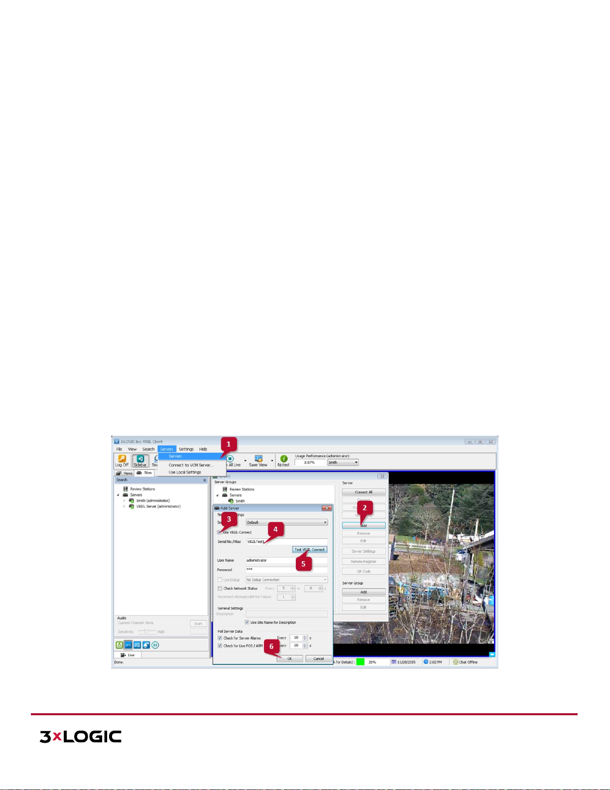
1. Launch VIGIL Client (Local Mode only; VCM mode will only display Servers from a networked VCM
Server) and select Servers from the Servers top menu. This will launch the Servers window. VISIX VSeries devices are considered edge recording devices and thus are recognized as their own VIGIL
Server within the VIGIL suite.
2. Click Add. This will deploy the Add/Edit VIGIL Server window.
3. Enable the Use VIGIL Connect option. If connecting using traditional network connection criteria is
desired, enter the cameras IP Address/DNS Name and confirm TCP/IP port status.
4. Enter in the VIGIL Connect alias of the desired V-Series Camera (VIGILTest1 used in the below
example). Skip this step if using traditional network connection criteria (IP/Port).
5. Click Test VIGIL Connect to confirm the camera can be communicated with through the Connect
system using the provided alias. Skip this step if using traditional network connection criteria
(IP/Port).
Figure 4-1 Adding V-Series Camera to VIGIL Client
Page 16
VISIX V-SERIES SOFTWARE USER MANUAL| VISIX V-Series All-in-One Camera – Gen II
12000 Pecos St., Suite 290, Westminster, CO 80234 | www.3xlogic.com | (877) 3XLOGIC
16
6. If the test is successful, then VIGIL Client can successfully communicate with the Server. Click OK at
the bottom of the Add Server window after configuring all required fields to save the new Server to
VIGIL Client. For more information on configuring VIGIL Servers, please see Section 5.1 of the VIGIL
Client Users Guide.
NOTE: The camera will be visible in the Client treeview and will be represented by a icon. The
camera video stream can be added to the VIGIL Client viewer in the same manner as VIGIL Server
cameras; Simply extend the camera’s drop-down menu and double click the icon to add it to the
viewer. Alternatively, a user can drag-and-drop the camera stream icon into the desired frame of the
VIGIL Client viewer.
For more information on configuring VIGIL Servers/V-Series All-in-One camera in VIGIL Client, please see Section
5.1 of the VIGIL Client Users Guide.
ADDING A V-SERIES CAMERA TO VIGIL VCM
Steps:
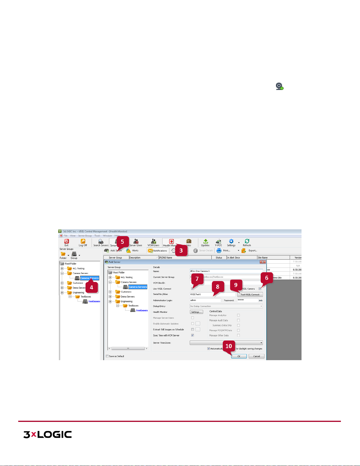
1. To add a V-Series camera to VCM for central management and health-monitoring purposes, launch a VCM
Client.
2. Log into a VCM Server.
Figure 4-2 : Adding an V-Series Camera to VCM
3. Click the Health Monitor button.
4. Select (left-click) a Server Group from the Server Groups sidebar. The V-Series camera will be added to
this group.
Page 17
VISIX V-SERIES SOFTWARE USER MANUAL| VISIX V-Series All-in-One Camera – Gen II
12000 Pecos St., Suite 290, Westminster, CO 80234 | www.3xlogic.com | (877) 3XLOGIC
17
5. Click the Add Server button (only available after selecting an applicable Server Group). This will launch
the Add/Edit Server form. VISIX V-Series devices (including the VX-2S-CPIR-W) are considered edge
recording devices, and thus are recognized as their own Server within the VIGIL suite, including VCM.
6. Check off VIGIL Camera. This will indicate to VCM that the device you are adding is a V-Series All-in-One
camera.
7. Check-off Use VIGIL Connect. Alternatively, if you wish to use traditional network connection criteria,
leave Use VIGIL Connect disabled and enter in IP/DNS Name and Port info (if using standard network
connection values, also ignore steps 8 and 9 of these instructions) for the device.
8. Enter the VIGIL Connect alias of the V-SERIEScamera in the Serial No./Alias field.
9. After entering an alias, click Test VIGIL Connect to ensure successful communication with the VIGIL
Connect system.
10. Fill in all remaining required fields and click OK to add the camera to your list of centrally managed VIGIL
Servers/V-Series Cameras.
If you experience issues connecting to the V-Series Camera in VCM, confirm the alias that has been entered is
correct. If all settings appear to be correct, contact 3xLOGIC for further instruction or reference Tech Tip 140028
VIGIL Connect Troubleshoot Guide for troubleshooting tips.
ADDING A V-SERIES CAMERA TO 3XLOGIC VIEW LITE II MOBILE (ANDROID AND IOS)
Steps:
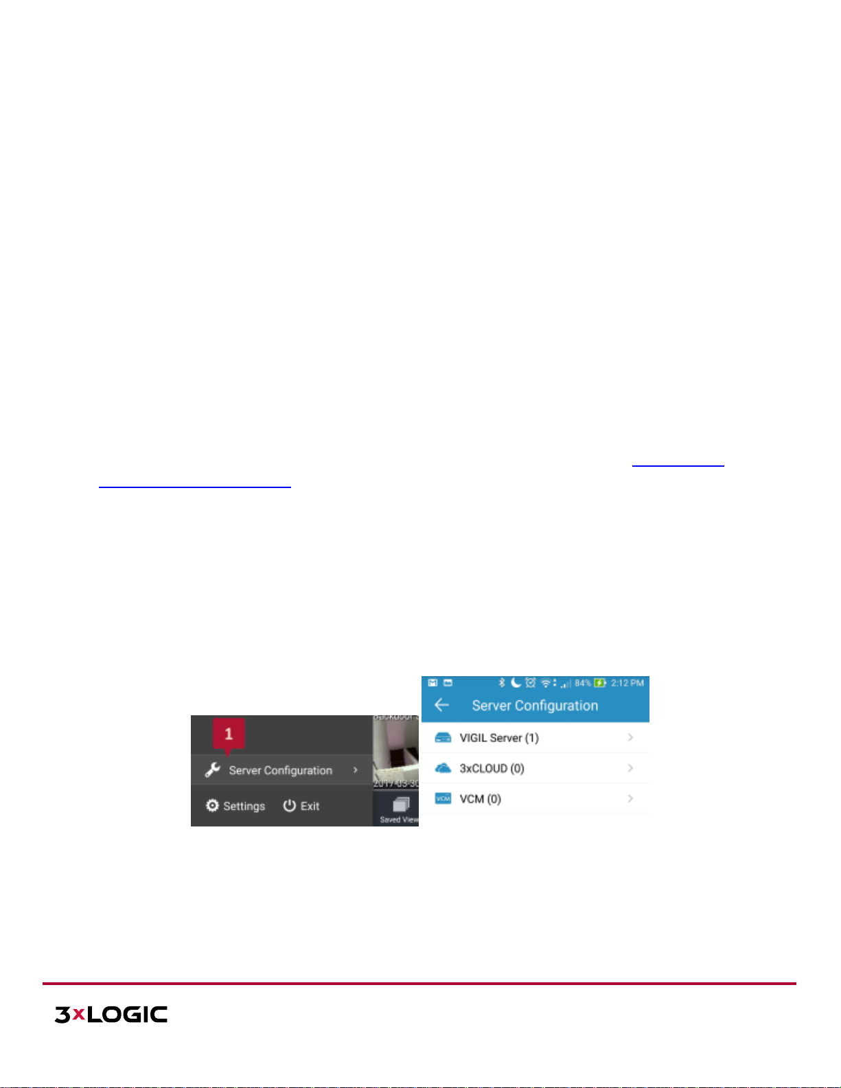
1. To interface a V-Series camera with 3xLOGIC’s View Lite II mobile app, launch the View Lite II app on your
mobile device (Android OS is pictured in the below screenshot, however, the process is identical in the iOS
version).
2. Open the Options side menu and select Server Configuration. The Video Source list will display.
Figure 4-3 Opening Video Source Menu
3. Select VIGIL Server. VISIX V-Series devices are considered edge recording devices, and thus are recognized
as their own VIGIL Server within View Lite II. The VIGIL Server window will now deploy. A menu of all VIGIL
Servers already interfaced with View Lite II will deploy.
Page 18
VISIX V-SERIES SOFTWARE USER MANUAL| VISIX V-Series All-in-One Camera – Gen II
12000 Pecos St., Suite 290, Westminster, CO 80234 | www.3xlogic.com | (877) 3XLOGIC
18
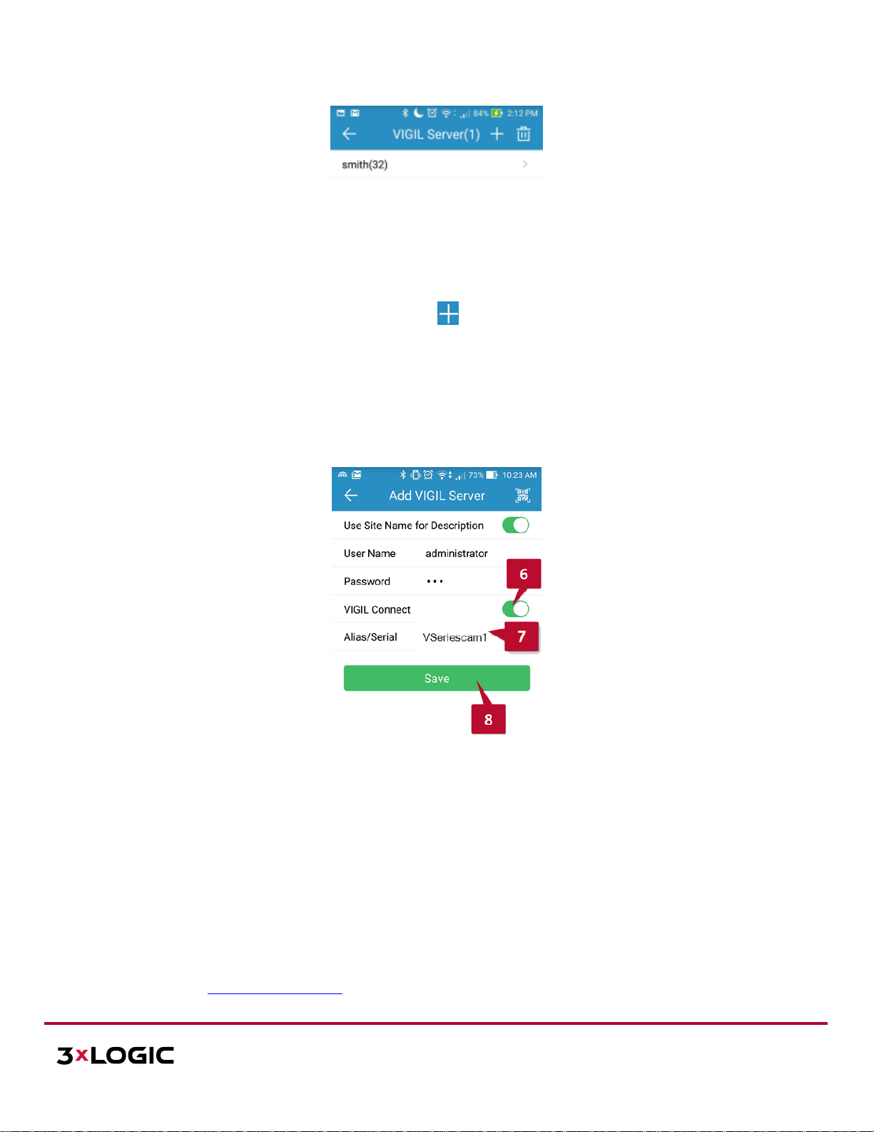
Figure 4-4 : Adding a Video Source - Add Video Source
4. To add a new instance of a video source, tap the icon.
5. Enable VIGIL Connect. Alternatively, if you wish to use traditional network connection criteria, leave VIGIL
Connect disabled and enter in an IP/DNS Name and Port info (if using standard network connection
criteria, also ignore step 6 of these instructions) for the device.
6. Enter in the VIGIL Connect alias for the desired VISIX V-Series camera (VSeriescam1 used in the above
example).
Figure 4-5 View Lite II - Add/Edit Server Form - Android
7. Fill in the remaining required fields and tap Save to save the V-Seies camera to View Lite II. A user may
now add the camera stream to the View Lite viewer using the same process as adding VIGIL Server, VCM
or 3xCLOUD networked cameras.
ADDING A V-SERIES CAMERA TO 3XCLOUD CROSS-PLATFORM WEB CLIENT
Steps:
1. To interface a V-Series All-in-One Camera with a 3xCLOUD web client account, login to your 3xCLOUD
account (www.3xlogiccloud.com).
Page 19
VISIX V-SERIES SOFTWARE USER MANUAL| VISIX V-Series All-in-One Camera – Gen II
12000 Pecos St., Suite 290, Westminster, CO 80234 | www.3xlogic.com | (877) 3XLOGIC
19
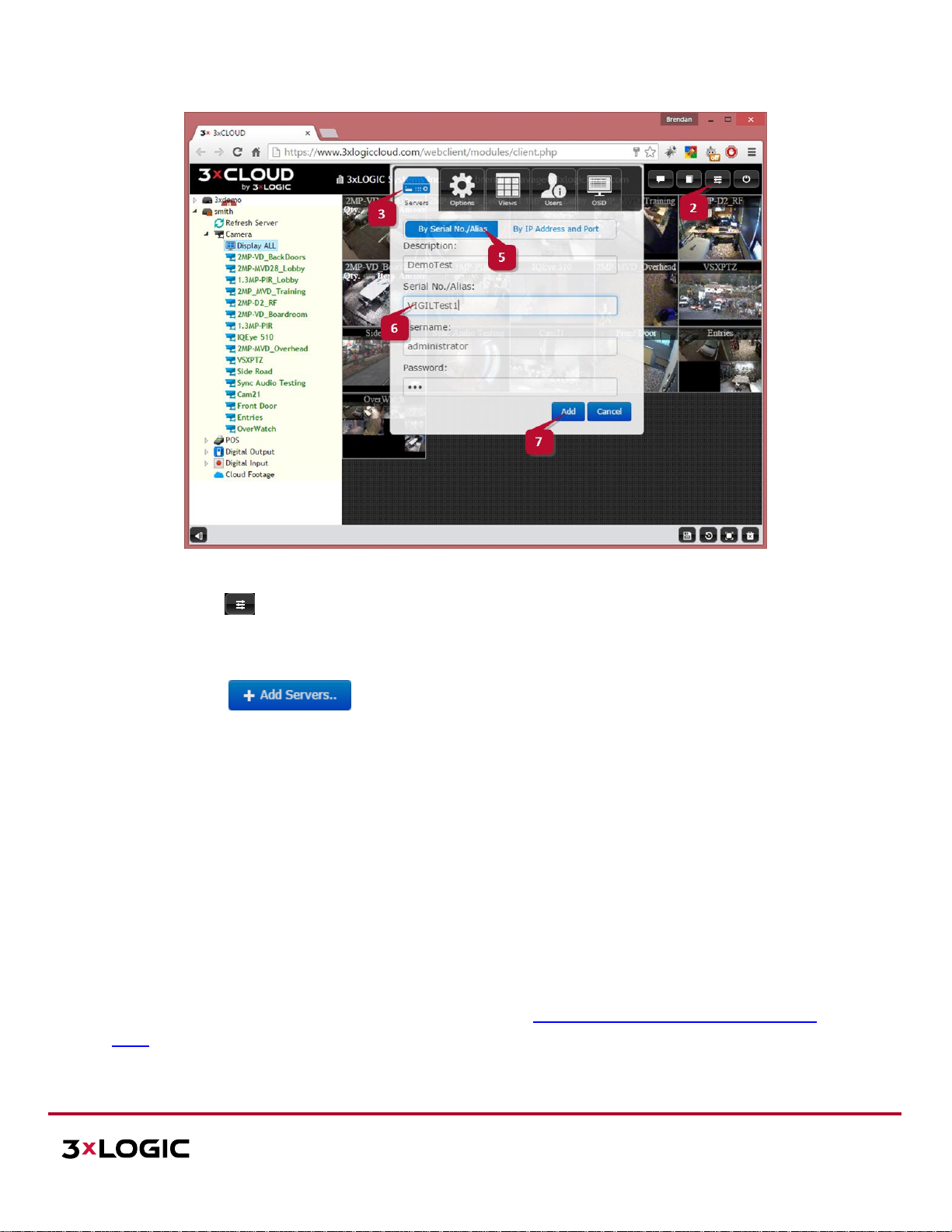
Figure 4-6 Adding an V-Series Camera to a 3xCLOUD Account
2. Click the button to open the Settings menu.
3. Select the Servers icon.
4. Click the button (not pictured above). This will deploy the Add/Edit VIGIL Server
form. VISIX V-Series devices are considered edge recording devices, and thus are recognized as their own
VIGIL Server within the VIGIL suite, including 3xCLOUD.
5. Click the By Serial No./Alias tab to configure the Server with a VIGIL Connect alias. If using traditional
network connection criteria is desired, click the By IP Address and Port button enter in an IP and Port info
(if using standard network connection criteria, also ignore step 6 of these instructions) for the device.
6. Enter the VIGIL Connect alias of the desired V-Series camera in the Serial No./Alias field (VIGILTest1 used
in the above example).
7. Fill in all required fields and click Add to save the V-Series camera to your 3xCLOUD VIGIL Server list.
The V-Series camera should now be available to add to your 3xCLOUD layout. If you experience connection issues,
confirm the connection info (IP Address and Port/VIGIL Connect Alias) you entered is correct. If all settings appear
to be correct, contact 3xLOGIC for further instruction or reference Tech Tip 140028 VIGIL Connect Troubleshoot
Guide for troubleshooting tips.
Page 20
VISIX V-SERIES SOFTWARE USER MANUAL| VISIX V-Series All-in-One Camera – Gen II
12000 Pecos St., Suite 290, Westminster, CO 80234 | www.3xlogic.com | (877) 3XLOGIC
20
5 Standard Network Connections
This section provides manual camera networking information. For basic camera networking, configuration and
setup, please reference Section 2 Camera Setup Options and Section 3 Camera Setup of this user guide for
instructions.
If you want to network the camera via LAN (Local Area Network), please refer to Section 5.1 Networking the
Camera - LAN.
If you want to network the camera via WAN (Wide Area Network), please refer to Section 5.2 Networking the
Camera -WAN.
5.1 Networking the Camera - LAN
To identify and configure the camera via LAN, you need to physically network the camera and access its browser
interface. This process can be expedited by installing and running either the 3xLOGIC All-in-One PC Setup Utility
(http://3xlogic.com/support-center/software) or the VSX Setup Utility mobile app (iOS or Android) on a device on
the same network as the camera. To change a camera’s IP address (for non-DHCP environments, networks
requiring static IP, etc…), the 3xLOGIC All-in-One PC Setup Utility can be used. See Section 3 for more information
on available setup tools and configuration methods.
WIRING OVER LAN
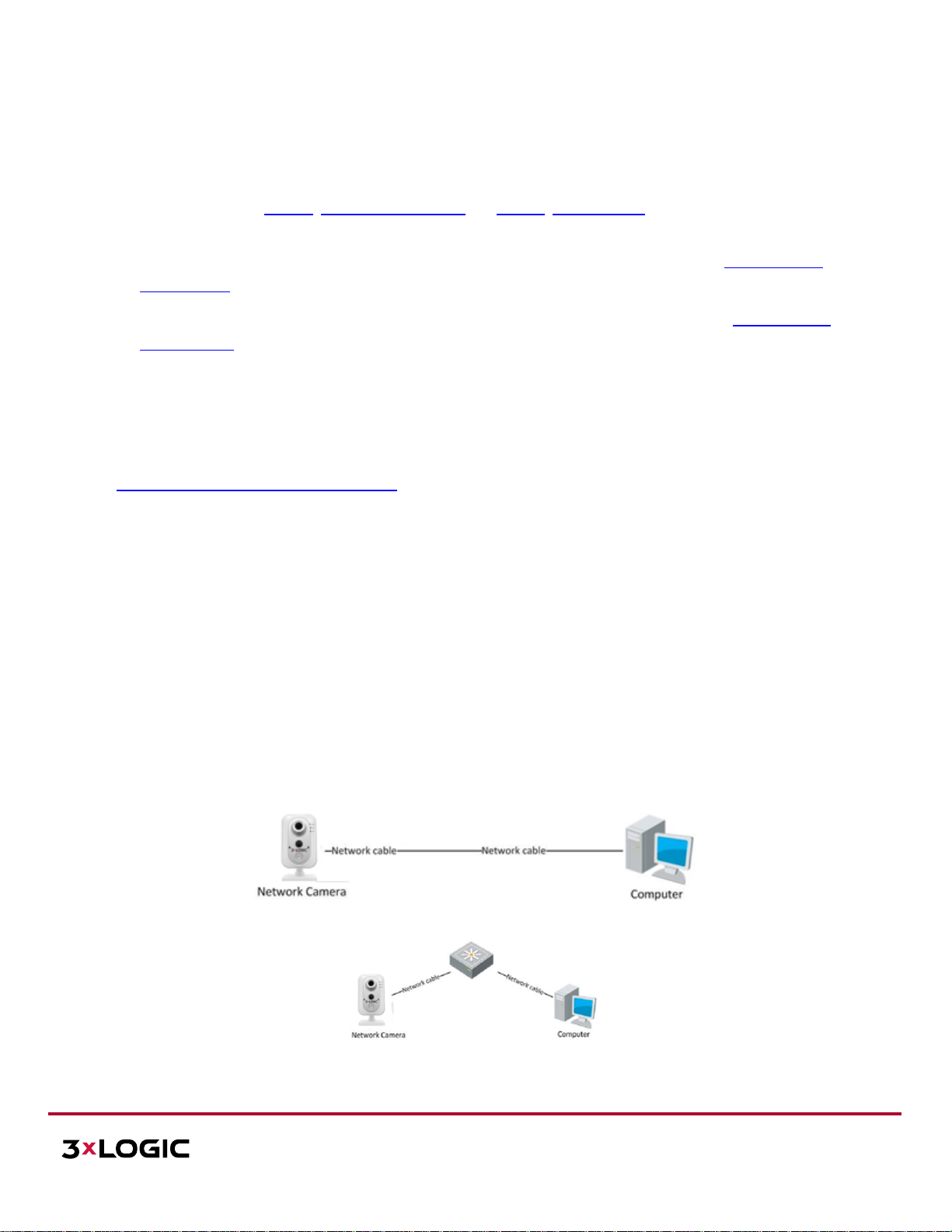
The following figures show the standard methods of LAN cable connection between a network camera and a
computer:
To test the network camera, you can directly connect the network camera to the computer with a network
cable as shown in Figure 2-1.
Refer to the Figure 2-2 to set network camera over the LAN via a switch or a router.
Figure 5-1 Connecting Directly
Figure 5-2 Connecting via a Switch or a Router
Page 21
VISIX V-SERIES SOFTWARE USER MANUAL| VISIX V-Series All-in-One Camera – Gen II
12000 Pecos St., Suite 290, Westminster, CO 80234 | www.3xlogic.com | (877) 3XLOGIC
21
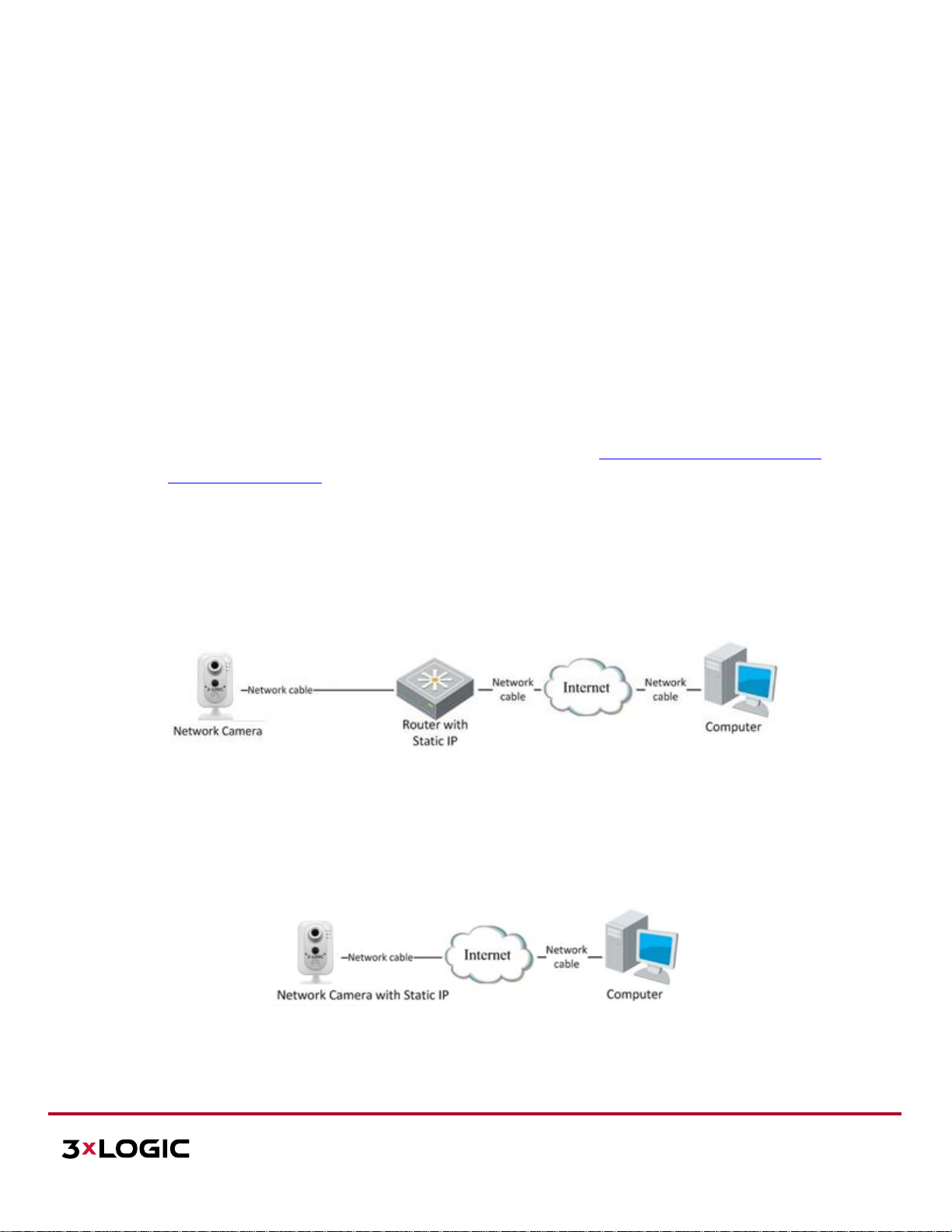
5.2 Networking the Camera - WAN
This section explains how to connect the network the camera via WAN using a static IP or a dynamic IP.
STATIC IP CONNECTION
Before you start:
Please apply a static IP from your ISP (Internet Service Provider). Using a static IP address, you can connect the
network camera via a router or connect it to the WAN directly.
Connecting the network camera via a router:
Steps:
1. Connect the network camera to the router.
2. Assign a LAN IP address, the subnet mask and the gateway. Refer to 3xLOGIC All-in-One PC Setup Tool –
Wired Connection Setup for instructions on configuring a LAN connection.
3. Save the LAN IP address configured in Step 2 as the static IP in the router.
4. Set port mapping, e.g., 80, 8000, and 554 ports. The steps for port mapping vary according to the
different routers. Please call the router manufacturer for assistance with port mapping.
5. Visit the network camera through a web browser or the client software over the internet.
Figure 5-3 Accessing the Camera through Router with Static IP
Connecting the network camera with static IP directly:
You can also save the static IP for the camera and directly connect it to the internet (modem) without using a
router.
Figure 5-4 Accessing the Camera with Static IP Directly
Page 22
VISIX V-SERIES SOFTWARE USER MANUAL| VISIX V-Series All-in-One Camera – Gen II
12000 Pecos St., Suite 290, Westminster, CO 80234 | www.3xlogic.com | (877) 3XLOGIC
22
DYNAMIC IP CONNECTION
Before you start:
Please apply a dynamic IP from your ISP. With a dynamic IP address, you can connect the network camera to a
modem or a router.
Connecting the Network Camera via a Router:
Steps:
1. Connect the network camera to the router.
2. In the camera settings, assign a LAN IP address, the subnet mask and the gateway. Refer to 3xLOGIC
All-in-One PC Setup Tool for instructions on configuring a LAN connection.
3. In the router, set the PPPoE user name, password and confirm the password.
4. Set port mapping. E.g. 80, 8000, and 554 ports. The steps for port mapping vary depending on
different routers. Please call the router manufacturer for assistance with port mapping.
5. Apply a domain name from a domain name provider.
6. Configure the DDNS settings in the setting interface of the router.
7. Visit the camera via the applied domain name.
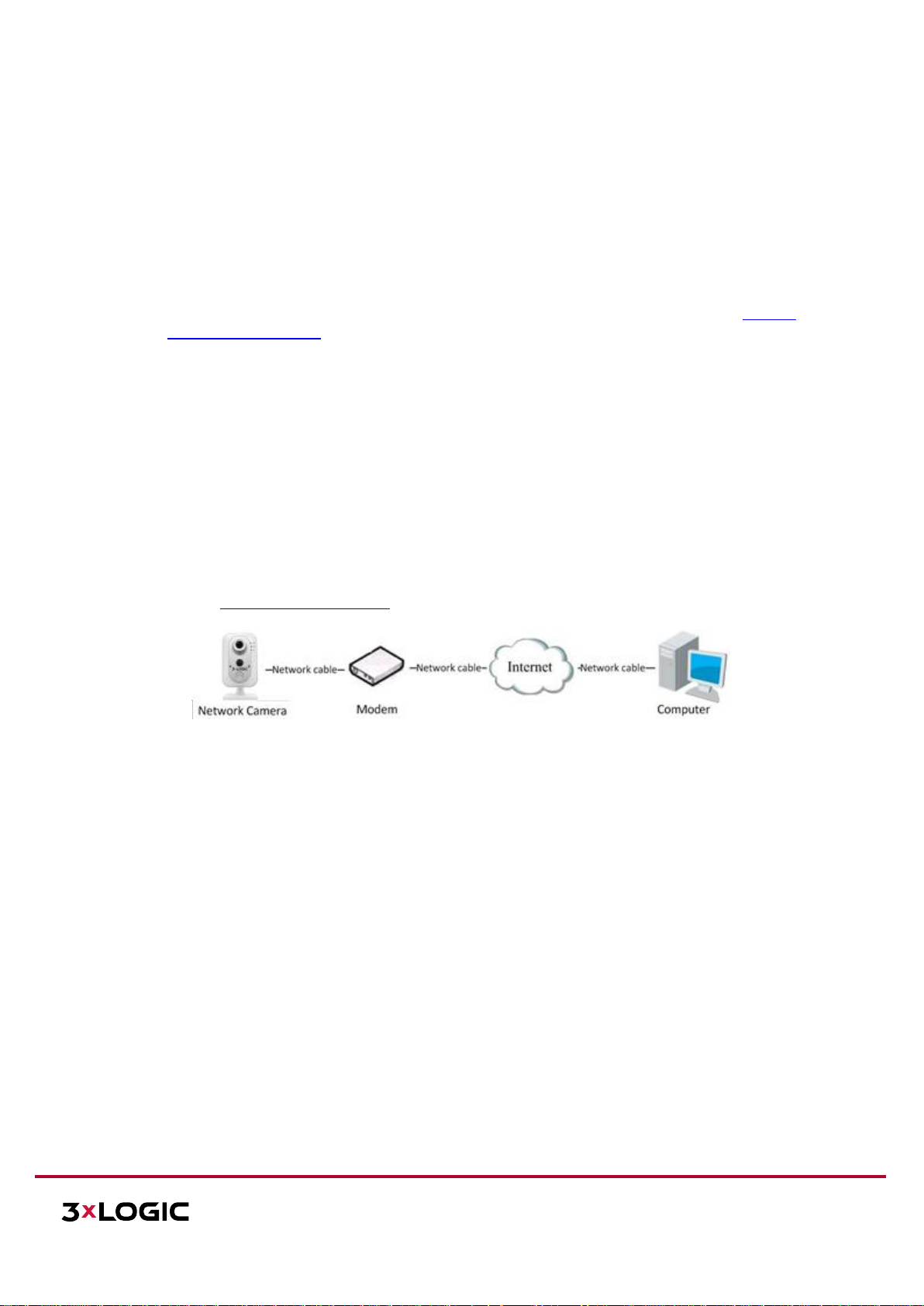
Connecting the Network Camera via a Modem:
This camera supports the PPPoE auto dial-up function. The camera gets a public IP address by ADSL dial-up
after the camera is connected to a modem. You need to configure the PPPoE parameters of the network
camera. Refer to Configuring PPPoE Settings for detailed configuration.
Figure 5-5 Accessing the Camera with Dynamic IP
NOTE: The obtained IP address is dynamically assigned via PPPoE, so the IP address always changes after
rebooting the camera. To solve the inconvenience of the dynamic IP, you need to get a domain name from the
DDNS provider (E.g. DynDns.com). Please follow the steps below for normal domain name resolution and
private domain name resolution to solve the problem.
Page 23
VISIX V-SERIES SOFTWARE USER MANUAL| VISIX V-Series All-in-One Camera – Gen II
12000 Pecos St., Suite 290, Westminster, CO 80234 | www.3xlogic.com | (877) 3XLOGIC
23
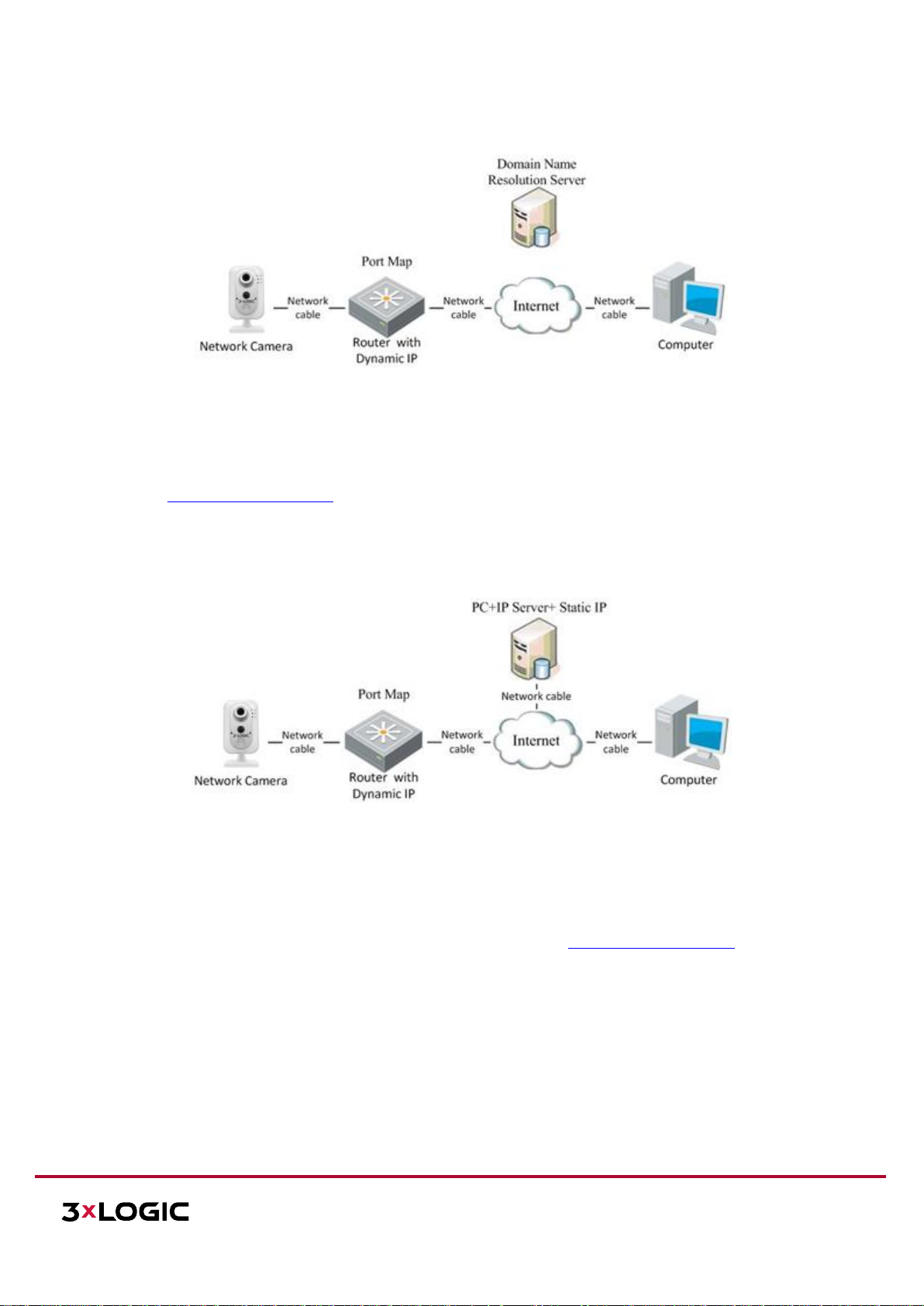
NORMAL DOMAIN NAME RESOLUTION
Figure 5-6 Normal Domain Name Resolution
Steps:
1. Apply a domain name from a domain name provider.
2. Configure the DDNS settings in the DDNS Settings interface of the network camera. Refer to
Configuring DDNS Settings for detailed configuration.
3. Visit the camera via the applied domain name.
PRIVATE DOMAIN NAME RESOLUTION
Figure 5-7 Private Domain Name Resolution
Steps:
1. Install and run the IP Server software on a computer with a static IP.
2. Access the network camera through the LAN with a web browser or the client software.
3. Enable DDNS and select IP Server as the protocol type. Refer to Configuring DDNS Settings for
detailed configuration.
Page 24
VISIX V-SERIES SOFTWARE USER MANUAL| VISIX V-Series All-in-One Camera – Gen II
12000 Pecos St., Suite 290, Westminster, CO 80234 | www.3xlogic.com | (877) 3XLOGIC
24
6 Accessing the V-Series Camera User Interface
6.1 Access UI via Web Browser
Steps:
1. Open a web browser.
2. Input the IP address of the network camera in the URL address bar, e.g., 192.0.0.64 and press the
Enter key to enter the login interface. Alternatively, if the camera is interfaced with VIGIL Client, the
web UI can be instantly deployed by right clicking the camera’s parent Site node in the VIGIL Client
treeview and selecting Server Settings.
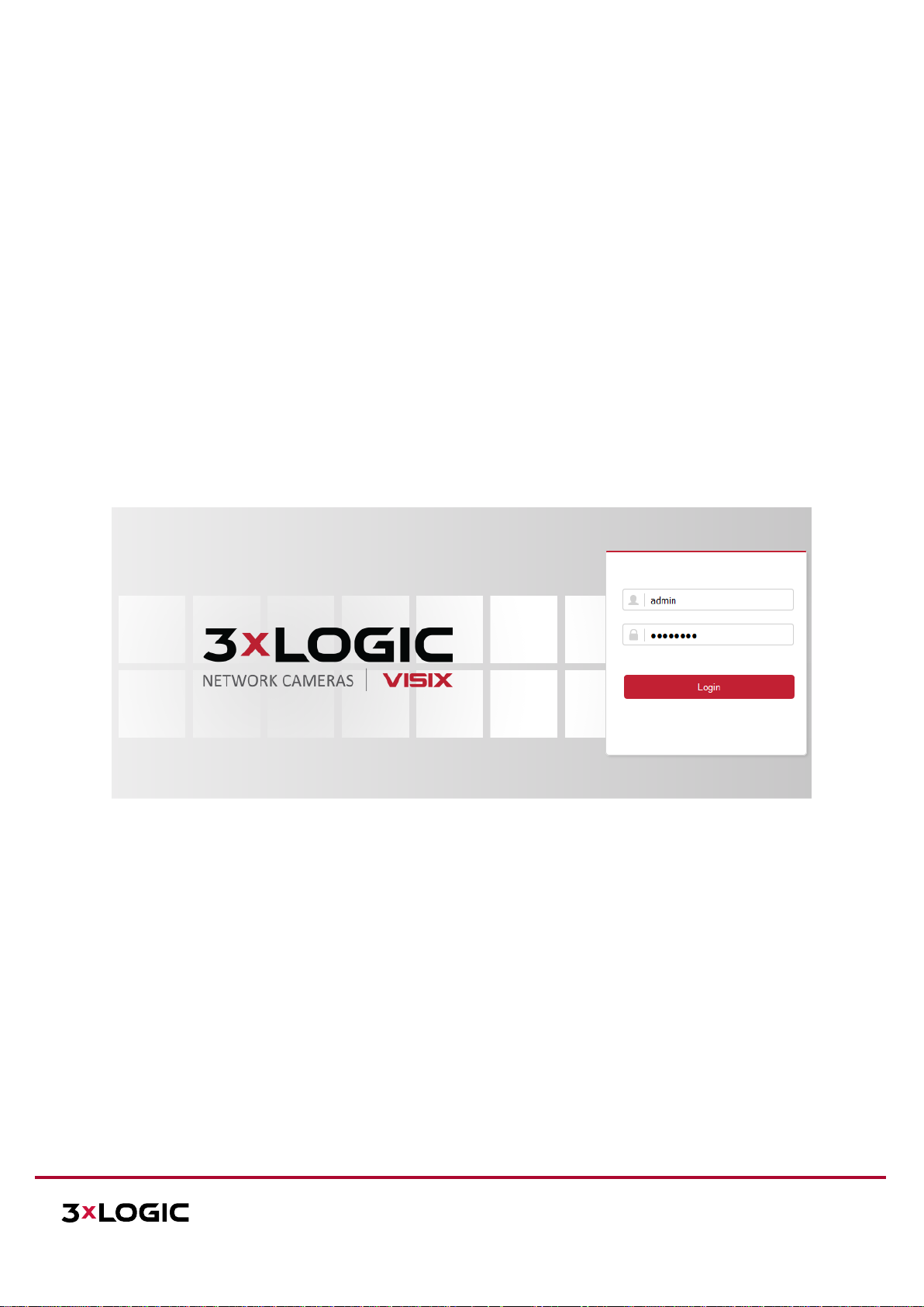
3. Input the user name and password and click Login.
NOTE: The default username/password is admin/12345. If the camera has already been configured
using one of 3xLOGIC’s setup tools (See Section 2 Camera Setup Options), then default credentials will
have been changed by the installer (this is a standard security precaution enforced by the setup
tools). Contact your security network administrator for credentials.
NOTE: English is the only supported language.
Figure 6-1 Login Interface
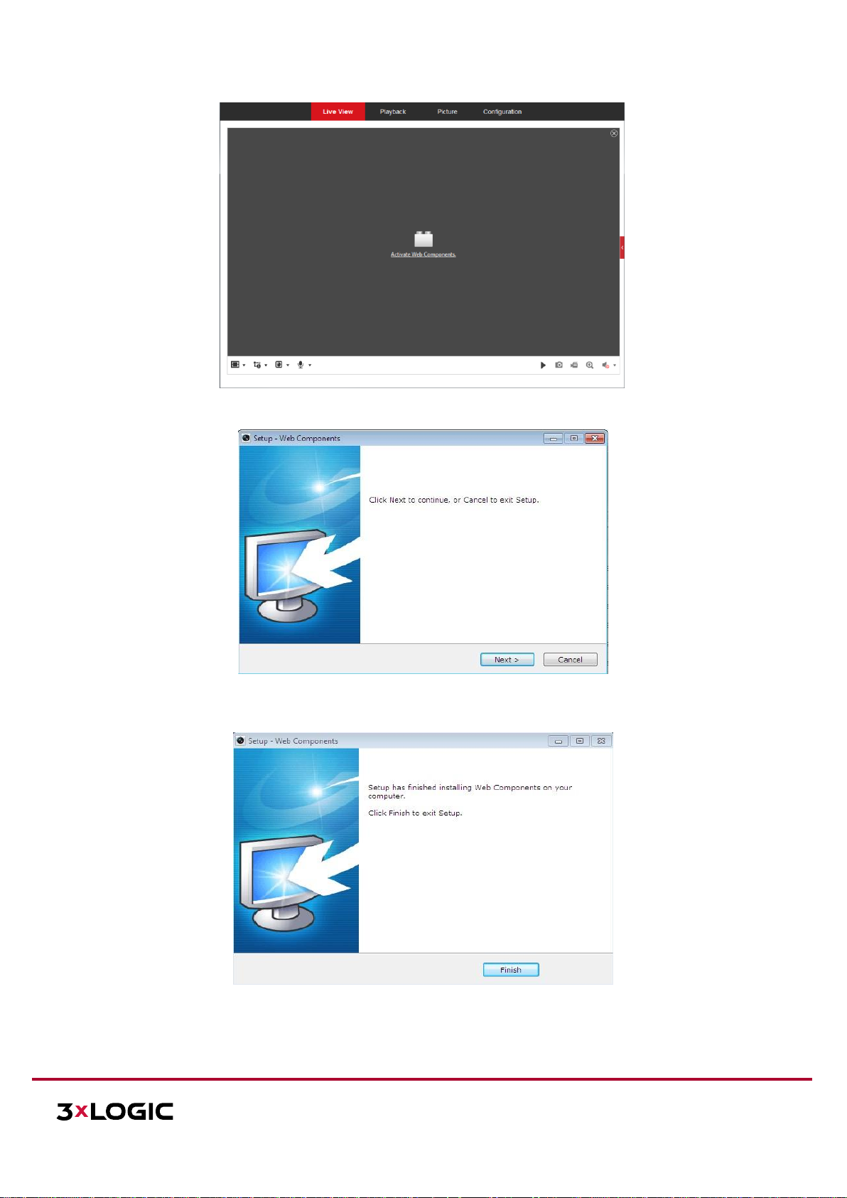
4. To view video and have full access to the camera’s configuration settings, you will need to install the
Web Components plug-in. Click “Activate Web Components” to start the plug-in installation.
NOTE: Depending on your web browser, you may be required to authorize the installer to run.
NOTE: You may have to close the web browser to install the plug-in. Reopen the web browser and log in
again after installing the plug-in.
Page 25
VISIX V-SERIES SOFTWARE USER MANUAL| VISIX V-Series All-in-One Camera – Gen II
12000 Pecos St., Suite 290, Westminster, CO 80234 | www.3xlogic.com | (877) 3XLOGIC
25
Figure 6-2 Download and Install Plug-in
Figure 6-3 Install Plug-in (1)
Figure 6-4 Install Plug-in (2)
Page 26
VISIX V-SERIES SOFTWARE USER MANUAL| VISIX V-Series All-in-One Camera – Gen II
12000 Pecos St., Suite 290, Westminster, CO 80234 | www.3xlogic.com | (877) 3XLOGIC
26
7 Live View
7.1 Live View Page
The live view page allows you to view the real-time video, capture images, utilize PTZ control, set/call presets
and configure video parameters.
Log in the network camera to enter the live view page, or you can click Live View on the menu bar of the main
page to enter the live view page.
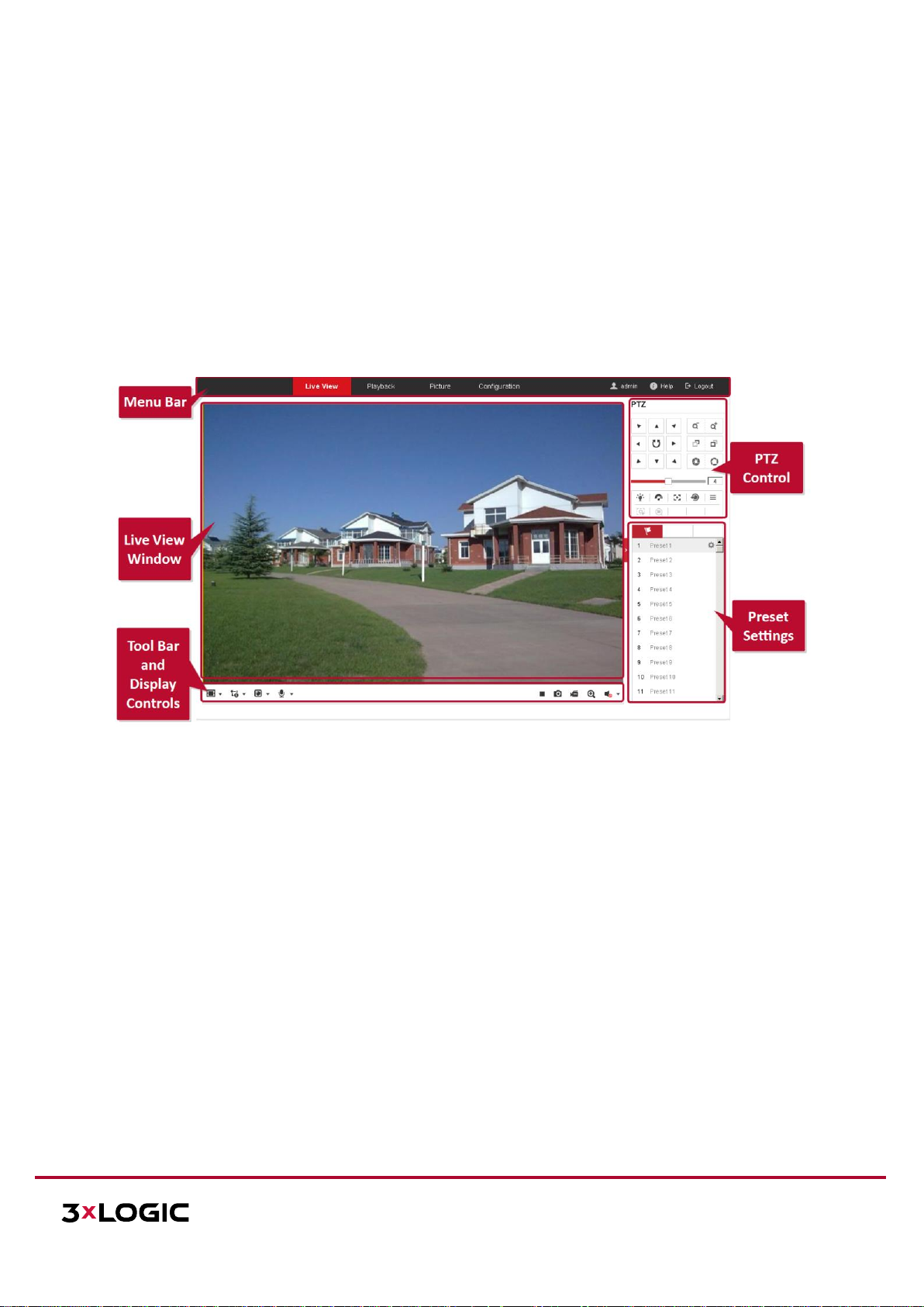
LIVE VIEW PAGE – COMPONENT DESCRIPTIONS
Figure 7-1 View Page
Menu Bar: Click each tab to enter Live View, Playback, Log and Configuration page respectively.
Display Control: Click available buttons to open corresponding tabs to change stream type and aspect
ratio. Click the plug-ins drop-down to select available plug-in
Live View Window: Displays live video from the camera.
Toolbar: Operations on the live view page, e.g., live view, capture, record, audio on/off, two-way audio,
etc.
PTZ Control: Panning, tilting and zooming functions for the camera and the lighter and wiper control (if
aux PTZ functions are supported or an external pan/tilt unit has been installed).
Preset Setting/Calling: Set and call the preset for the camera (if supports PTZ preset functionality is
supported or an external pan/tilt unit has been installed).
Page 27
VISIX V-SERIES SOFTWARE USER MANUAL| VISIX V-Series All-in-One Camera – Gen II
12000 Pecos St., Suite 290, Westminster, CO 80234 | www.3xlogic.com | (877) 3XLOGIC
27
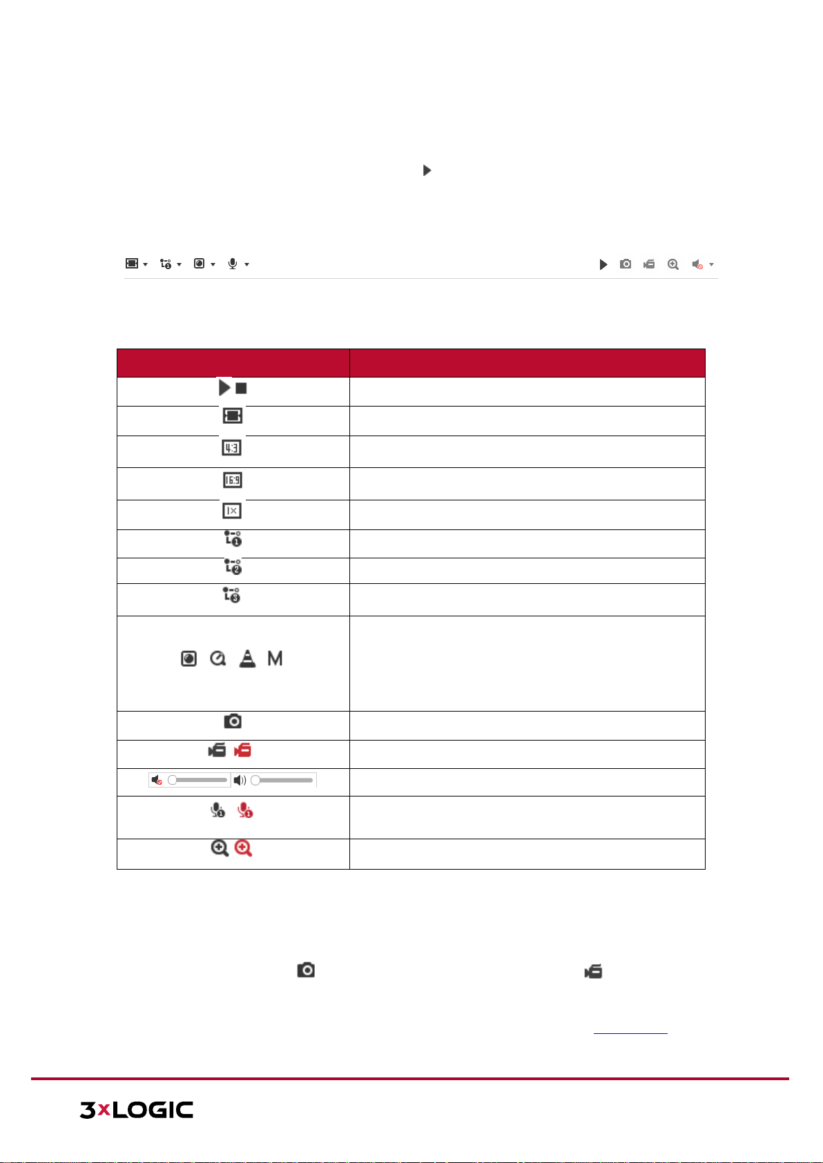
7.2 Starting Live View
In the live view window as shown in Figure 7-1, click on the toolbar to start the live view of the
camera.
Figure 7-2 Live View Toolbar
Icon
Description
Start/Stop live view.
Self-adaptive window size.
Aspect Ratio: 4:3.
Aspect Ratio: 16:9.
Default aspect ratio.
Live view main stream.
Live view sub stream.
Live view third stream.
Third-party plugins: Click to choose an active third-party
plug-in. For IE (internet explorer) users, WebComponents
and QuickTime are available. For Non-IE users,
WebComponents, QuickTime, VLC or MJPEG are selectable
if they are supported by the web browser.
Manually take a stillshot.
Manually start/stop recording.
Audio on and adjust volume /Mute.
/
Engage two-way audio (multiple channels available on
applicable devices)
Turn on/off digital zooming function.
Table 5-1 Live View Toolbar - Descriptions
7.3 Recording and Capturing Pictures Manually
In the live view interface, click on the toolbar to capture live stillshots or click to manually
trigger recording. Destination paths for captured pictures and clips can be set on the Configuration >
Local Configuration page. To configure remote scheduled recording, please refer to Section 13.1.
NOTE: The captured image will be saved as JPEG file or BMP file to the defined destination path.
Page 28
VISIX V-SERIES SOFTWARE USER MANUAL| VISIX V-Series All-in-One Camera – Gen II
12000 Pecos St., Suite 290, Westminster, CO 80234 | www.3xlogic.com | (877) 3XLOGIC
28
7.4 Operating PTZ Control
In the live view interface, you can use the PTZ control buttons to issue pan/tilt/zoom commands to
applicable cameras.
Before you start:
To utilize PTZ control, the camera connected to the network must support the PTZ function or a
pan/tilt unit has been installed to the camera. Please properly set the PTZ parameters on RS-485
settings page referring to Section 8.2 - RS-485 Settings.
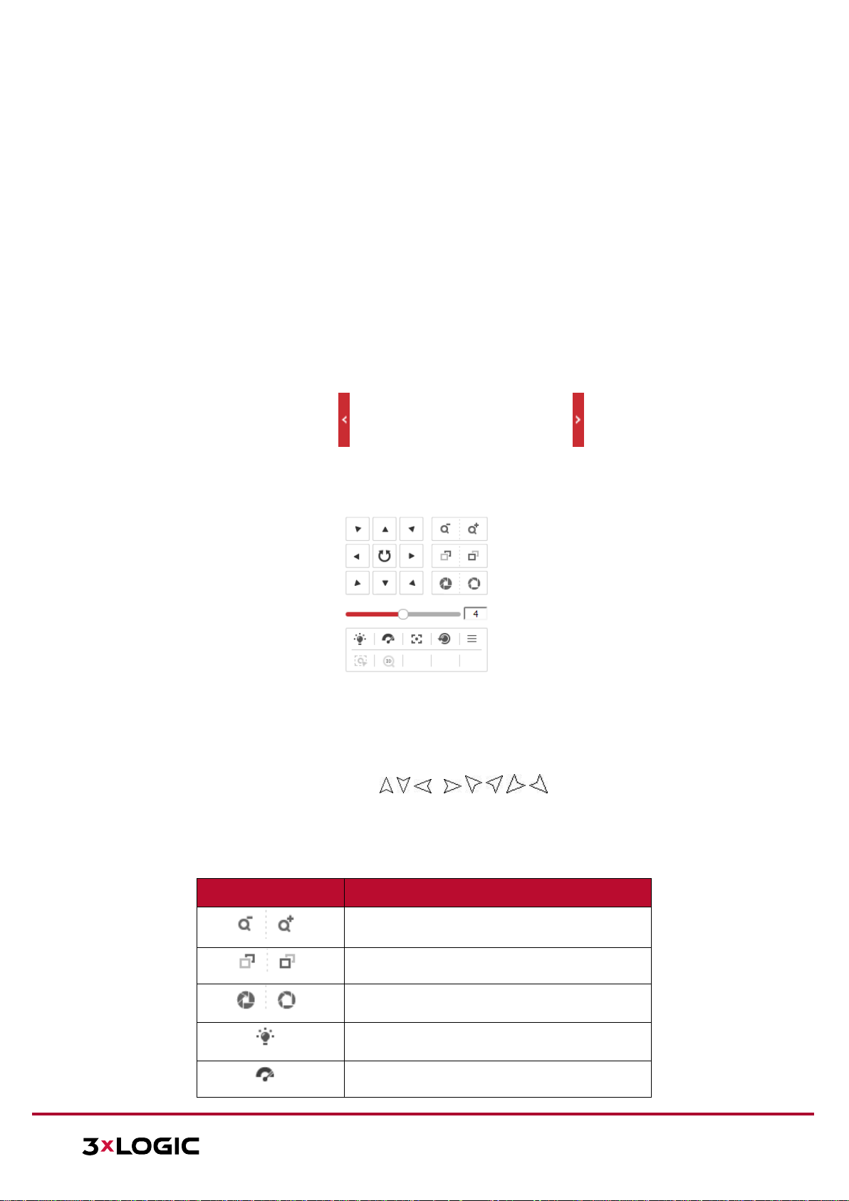
PTZ CONTROL PANEL
Steps:
1. On the live view page, click to show the PTZ control panel or click to hide it.
2. Click the direction buttons to control the pan/tilt movement.
Figure 7-3 PTZ Control Panel
3. Click the zoom/iris/focus buttons to utilize lens control.
There are 8 direction arrows ( ) in the live view window
when you click and drag the mouse in the relative positions.
For cameras which support lens movement only, the direction buttons are invalid.
Icon
Description
Zoom in/out
Focus near/far
Iris +/-
Light on/off
Wiper on/off
, , , ,
,
Page 29
VISIX V-SERIES SOFTWARE USER MANUAL| VISIX V-Series All-in-One Camera – Gen II
12000 Pecos St., Suite 290, Westminster, CO 80234 | www.3xlogic.com | (877) 3XLOGIC
29
One-touch focus
Initialize lens
Adjust speed of pan/tilt movements
Adjust speed of pan/tilt movements
Start Manual Tracking
Start 3D Zoom
Table 5-2 Descriptions of PTZ Control Panel
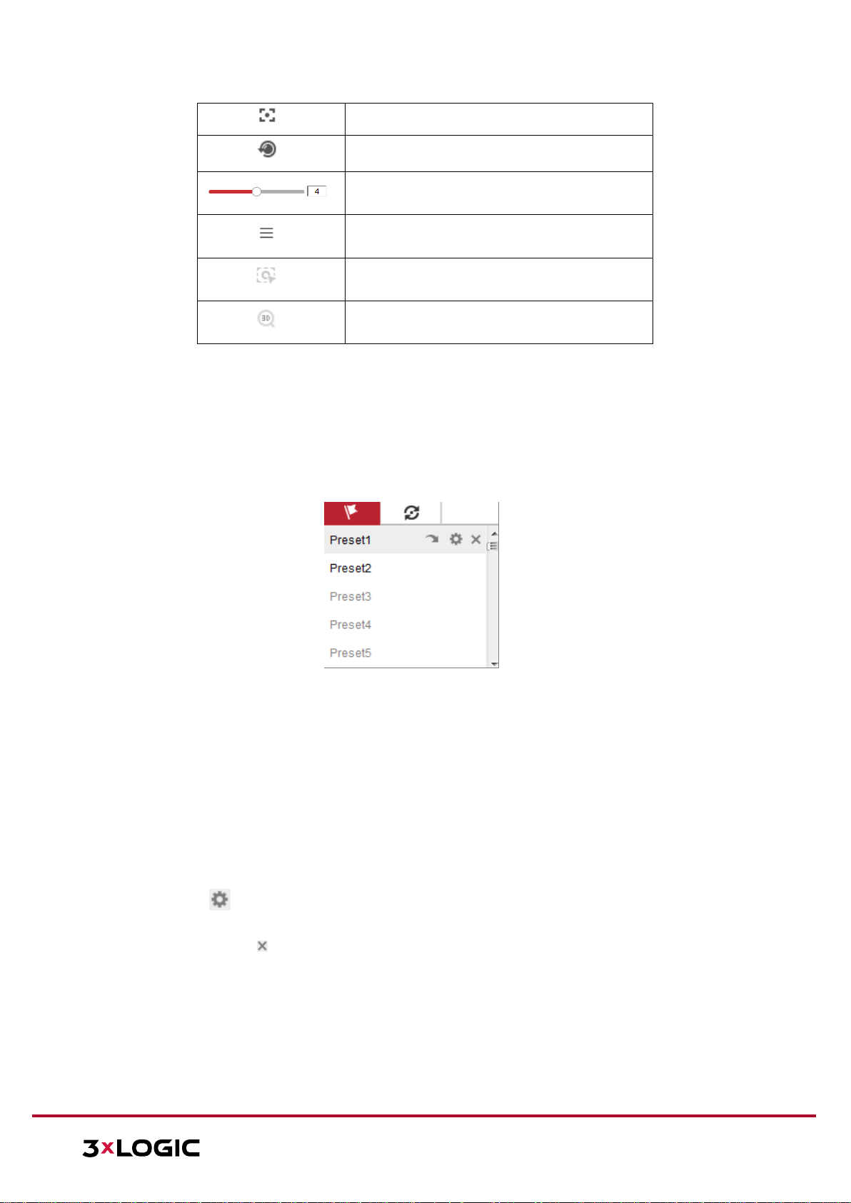
SETTING A PRESET
Steps:
1. In the PTZ control panel, select a preset number from the preset list.
Figure 7-4 Setting a Preset
2. Use the PTZ control buttons to aim the camera toward the desired position.
a. Pan the camera to the right or left.
b. Tilt the camera up or down.
c. Zoom in or out.
d. Refocus the lens.
3. Click to save the current camera position to the selected preset.
4. You can click to delete the preset.
NOTE: You can configure up to 128 presets.
CALLING A PRESET
This feature enables the camera to point to a specified preset scene manually or when an event takes
place.
Page 30
VISIX V-SERIES SOFTWARE USER MANUAL| VISIX V-Series All-in-One Camera – Gen II
12000 Pecos St., Suite 290, Westminster, CO 80234 | www.3xlogic.com | (877) 3XLOGIC
30
A user can call a preset at any time to shift position to the desired preset coordinates.
In the PTZ control panel, select a defined preset from the list and click to call the preset.
Alternatively, select the Presets interface, and call the preset by manually typing the preset No.
Figure 7-5 Calling a Preset
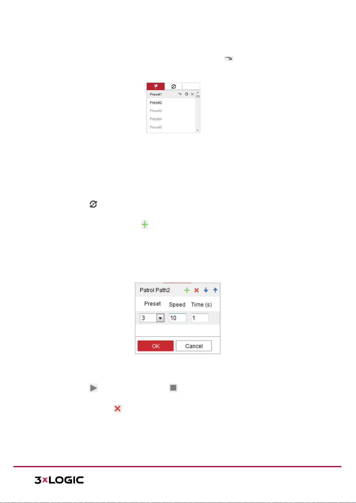
SETTING/CALLING A PATROL
NOTE: No less than 2 presets must be configured before you set a patrol.
Steps:
1. Click to enter the patrol configuration interface.
2. Select a path No., and click to add the configured presets.
3. Select the preset, and input the patrol duration and patrol speed.
4. Click OK to save the first preset.
5. Follow the steps above to add the other presets.
Figure 7-6 Add Patrol Path
6. Click OK to save a patrol.
7. Click to start the patrol, and click to stop it.
8. (Optional) Click to delete a patrol.
Page 31

VISIX V-SERIES SOFTWARE USER MANUAL| VISIX V-Series All-in-One Camera – Gen II
12000 Pecos St., Suite 290, Westminster, CO 80234 | www.3xlogic.com | (877) 3XLOGIC
31
8 Playback
This section explains how to view recorded video files stored on a configured network drive or the
camera’s local SD card via the camera’s browser interface.
Note: Playback footage can also be retrieved via VIGIL Client and other VIGIL VMS clients that have
been properly interfaced with the camera.
Steps:
1. Click Playback on the menu bar to enter the playback interface.
Figure 8-1 Playback Interface
2. Select the date and click Search.
Page 32

VISIX V-SERIES SOFTWARE USER MANUAL| VISIX V-Series All-in-One Camera – Gen II
12000 Pecos St., Suite 290, Westminster, CO 80234 | www.3xlogic.com | (877) 3XLOGIC
32
Figure 8-2 Search Video
Page 33

VISIX V-SERIES SOFTWARE USER MANUAL| VISIX V-Series All-in-One Camera – Gen II
12000 Pecos St., Suite 290, Westminster, CO 80234 | www.3xlogic.com | (877) 3XLOGIC
33
3. Click to play the video files found on this date. The toolbar on the bottom of Playback
interface can be used to control the active playback footage.
Figure 8-3 Playback Toolbar
Button
Operation
Button
Operation
Play
Capture and download a
stillshot.
Pause
Start/Stop clipping video
files
Stop
Audio on and adjust
volume/Mute
Increase / Decrease
playback speed
Download files
Playback by frame
Enable/Disable digital zoom
Table 8-1 Description of the buttons
NOTE: You can choose the local file paths for downloaded playback files and snapshots/pictures via
the Local Configuration interface. Please refer to Section 8.1 - Configuring Local Parameters for
details. Drag the progress bar with the mouse to locate your desired playback point. You can also
input the time in the Set playback time field and click to locate the playback point. Click
to zoom out of or into the progress bar.
Figure 8-4 Set Playback Time
Figure 8-5 Progress Bar
Page 34

VISIX V-SERIES SOFTWARE USER MANUAL| VISIX V-Series All-in-One Camera – Gen II
12000 Pecos St., Suite 290, Westminster, CO 80234 | www.3xlogic.com | (877) 3XLOGIC
34
The different colors for video in the progress bar represent the different recording modes.
Figure 8-6 Recording Modes
Page 35

VISIX V-SERIES SOFTWARE USER MANUAL| VISIX V-Series All-in-One Camera – Gen II
12000 Pecos St., Suite 290, Westminster, CO 80234 | www.3xlogic.com | (877) 3XLOGIC
35
9 Picture
Click Picture to enter the picture searching interface. You can search, view, and download
pictures/snapshots stored in the local or network storage.
NOTES:
► Make sure an HDD, NAS or memory card are properly configured before you initiate the
picture search.
► Make sure the capture schedule is configured. Go to Configuration > Storage > Schedule
Settings > Capture to set the capture schedule.
Figure 9-1 Picture Search Interface
Steps:
1. Select the file type from the dropdown list. Continuous, Motion, Alarm, Motion | Alarm,
Motion & Alarm, Line Crossing, Intrusion Detection, and Scene Change Detection are
selectable.
2. Select the start time and end time.
3. Click Search to display a list of results.
4. Check off desired snapshots and click Download to download the selected images.
NOTE: Up to 4000 images can be available in the search index simultaneously.
Page 36

VISIX V-SERIES SOFTWARE USER MANUAL| VISIX V-Series All-in-One Camera – Gen II
12000 Pecos St., Suite 290, Westminster, CO 80234 | www.3xlogic.com | (877) 3XLOGIC
36
10 Network Camera Configuration
10.1 Configuring Local Parameters
The Local Configuration settings allow the user to set the parameters for live view, recorded files and
captured pictures/stills. The recorded files and captured pictures/stillshots can be captured using the
camera’s browser UI and are saved to a destination path on your local system.
Steps:
1. Enter the Local Configuration interface: Configuration > Local.
Figure 10-1 Local Configuration Interface
2. Configure the following settings:
Live View Parameters:
Set the Protocol Type and Live View Performance settings.
Protocol Type: TCP, UDP, MULTICAST and HTTP are selectable.
► TCP: Ensures complete delivery of streaming data and better video quality,
however, real-time transmission will be affected (skipped frames, etc…)
► UDP: Provides real-time audio and video streams though video quality may be
lowered due to bandwidth limitations.
► HTTP: Allows the same quality as TCP without setting specific ports for streaming
under some network environments.
► MULTICAST: It’s recommended to select MCAST type when using the Multicast
function. For detailed information about Multicast, refer to Section 9.1
Configuring Basic Settings – Configuring TCP/IP Settings.
Play Performance: Set the play performance to Shortest Delay or Auto.
Rules: Refers to on-screen tracking for rules configured on the camera. Select enable or
disable to display or not display colored trackers when motion detection, face detection, or
intrusion detection is triggered. E.g., If face detection is enabled and this option is active,
Page 37

VISIX V-SERIES SOFTWARE USER MANUAL| VISIX V-Series All-in-One Camera – Gen II
12000 Pecos St., Suite 290, Westminster, CO 80234 | www.3xlogic.com | (877) 3XLOGIC
37
when a face is detected it will be marked with a green rectangle on the live view.
Image Format: Choose the image format for picture/stillshot capture.
Record File Settings
Set the destination of recorded video files. Applies only for video recorded manually via the browser
UI.
Record File Size: Select the packed size of the manually recorded and downloaded video
files to 256M, 512M or 1G. After the selection, the maximum record file size is the value
you selected.
Save record files to: Set the destination for manually recorded video files.
Save downloaded files to: Set the destination for files downloaded/exported via playback
mode.
Picture and Clip Settings
Set the destination of captured pictures/stillshots and clipped video files. Valid only for media captured
manually via the web browser UI.
Save snapshots in live view to: Set the destination of the manually captured pictures in live
view mode.
Save snapshots when playback to: Set the destination of the captured pictures in playback
mode.
Save clips to: Set the destination of clipped video files in playback mode.
NOTE: You can click Browse to change the directory for saving the clips and pictures, and
click Open to select the desired folder.
3. Click Save to save the settings.
10.2 Configure System Settings
Follow the instructions below to configure System Settings, including Basic System Settings,
Maintenance, Security, and User Management, etc.
CONFIGURING BASIC INFORMATION
In the Basic Information interface, you can edit the Device Name and Device No.
Other information regarding the network camera, such as Model, Serial No., Firmware Version,
Encoding Version, Number of Channels, Number of HDDs, Number of Alarm Input and Number of
Alarm Output is displayed. The information cannot be changed in this menu and should be used as
reference for future maintenance or modification.
1. Enter the Device Information interface: Configuration > System > System Settings > Basic
Information.
Page 38

VISIX V-SERIES SOFTWARE USER MANUAL| VISIX V-Series All-in-One Camera – Gen II
12000 Pecos St., Suite 290, Westminster, CO 80234 | www.3xlogic.com | (877) 3XLOGIC
38
Figure 10-2 Basic Information
CONFIGURING TIME SETTINGS
You can follow the instructions in this section to configure Time Synchronization and DST settings.
Steps:
1. Enter the Time Settings interface: Configuration > System> System Settings > Time Settings.
Figure 10-3 Time Settings
2. Select your location’s Time Zone from the drop-down menu.
3. Configure the NTP settings.
Page 39

VISIX V-SERIES SOFTWARE USER MANUAL| VISIX V-Series All-in-One Camera – Gen II
12000 Pecos St., Suite 290, Westminster, CO 80234 | www.3xlogic.com | (877) 3XLOGIC
39
2. Click to enable the NTP function.
3. Configure the following settings:
Server Address: IP address of NTP server.
NTP Port: Port of NTP server.
Interval: The polling interval between the device and the NTP server.
4. (Optional) You can click the Test button to test the time synchronization function via NTP
server.
Figure 10-4 Time Sync by NTP Server
NOTE: If the camera is connected to a public network, you should use an NTP server which
features time synchronization functionality, such as the server at the National Time Center
(IP Address: 210.72.145.44). If the camera is located in a customized, closed network, NTP
software can be used to establish a NTP server for time synchronization.
Manual Time Synchronization:
1. Check the Manual Time Sync. item to enable the manual time synchronization function.
2. Click the icon to select a date and time from the pop-up calendar.
3. (Optional) Check the Sync. with computer time item to synchronize the time of the device
with that of the local PC.
Figure 10-5 Time Sync Manually
4. Click Save to save the settings.
Page 40

VISIX V-SERIES SOFTWARE USER MANUAL| VISIX V-Series All-in-One Camera – Gen II
12000 Pecos St., Suite 290, Westminster, CO 80234 | www.3xlogic.com | (877) 3XLOGIC
40
CONFIGURING RS232 SETTINGS
The RS232 port can be used in two ways:
Parameters Configuration: Connect a computer to the camera through the serial port. Device
parameters can be configured by using software such as HyperTerminal. The serial port
parameters must be the same as the serial port parameters of the camera.
Transparent Channel: Connect a serial device directly to the camera. The serial device will be
controlled remotely by the computer through the network.
Steps:
1. Enter the RS232 Port Settings interface: Configuration> System > System Settings > RS232.
2. Configure the Baud Rate, Data Bit, Stop Bit, Parity, Flow Control, and Usage.
Figure 10-6 RS232 Settings
NOTE: If you want to connect the camera via the RS232 port, the parameters of the RS232 should be
exactly the same as the parameters you configured here.
3. Click Save to save the settings.
CONFIGURING RS485 SETTINGS
The RS485 serial port is used to control a third party PTZ mount for the camera. The configuring of the
PTZ parameters should always be performed before controlling the PTZ unit.
Steps:
1. Enter the RS-485 Port Settings interface: Configuration > System > System Settings > RS485.
Page 41

VISIX V-SERIES SOFTWARE USER MANUAL| VISIX V-Series All-in-One Camera – Gen II
12000 Pecos St., Suite 290, Westminster, CO 80234 | www.3xlogic.com | (877) 3XLOGIC
41
Figure 10-7 RS-485 Settings
2. Set the RS485 parameters and click Save to save the settings.
By default, the Baud Rate is set as 9600 bps, the Data Bit is 8, the stop bit is 1 and the Parity and
Flow Control is None.
NOTE: The Baud Rate, PTZ Protocol and PTZ Address parameters should be exactly the same as the
PTZ camera parameters.
CONFIGURING DST SETTINGS
Daylight Savings Time (DST) is a way of making better use of the natural daylight by setting your clock
forward one hour during the summer months, and back again in the fall.
Configure DST according to your surveillance environment’s need.
Steps:
1. Enter the DST configuration interface: Configuration > System > System Settings > DST
Figure 10-8 DST Settings
2. Select the start time and the end time.
3. Select the DST Bias.
4. Click Save to activate the settings.
Page 42

VISIX V-SERIES SOFTWARE USER MANUAL| VISIX V-Series All-in-One Camera – Gen II
12000 Pecos St., Suite 290, Westminster, CO 80234 | www.3xlogic.com | (877) 3XLOGIC
42
CONFIGURING EXTERNAL DEVICES
External Device settings apply to supported external devices, including a housing wiper or LED
lighting. Settings for these devices can be configured here. Supported external devices vary according
to different camera models.
Steps:
1. Enter the External Device configuration interface: Configuration > System > System Settings >
External Device
Figure 10-9 External Device Settings
2. Check the Enable Supplement Light checkbox to enable the LED Light.
3. Move the slider to adjust the low beam brightness and high beam brightness.
4. Select the mode for LED light. Timing and Auto are selectable.
Timing: The LED will be turned according to the schedule. You should set the Start Time and
End Time.
Figure 10-10 Set Schedule
Auto: The LED will be turned on according to the environment illumination.
5. Click Save to save the settings.
CONFIGURING VCA RESOURCE
The VCA Resource interface offers you options to enable certain VCA functions according to actual
need when several VCA functions are available. It helps allocate more resources to the required
functions.
Figure 10-11 VCA Resource Configuration
Page 43

VISIX V-SERIES SOFTWARE USER MANUAL| VISIX V-Series All-in-One Camera – Gen II
12000 Pecos St., Suite 290, Westminster, CO 80234 | www.3xlogic.com | (877) 3XLOGIC
43
Steps:
1. Enter VCA Resource configuration interface: Configuration > System > System Settings > VCA
Resource
2. Select a desired VCA combination. SMART Event + Face Detection and SMART Event + Heat Map
are selectable.
3. Click Save to save the settings. A reboot is required after setting the VCA Resource.
NOTES:
► VCA Resource function varies according to different camera models.
► Face Detection and Heat Map are mutually exclusive. When SMART Event + Heat Map is
enabled, Face Detection interface will not be displayed.
► This function may not be supported by some camera models.
10.3 Maintenance
UPGRADE & MAINTENANCE
The Upgrade & Maintenance interface allows you to process device operations, including reboot,
partial restore, restore to default, export/import of configuration files, and device upgrades.
Enter the Maintenance interface: Configuration > System > Maintenance > Upgrade & Maintenance
Reboot: Restart the device.
Restore: Reset all the parameters, except the IP parameters and User information, to default
settings.
Default: Restore all the parameters to their factory default state.
NOTE: After restoring the default settings, the IP address is also restored to the default IP
address.
Export/Import Config. File: Configuration file is used for the batch configuration of the camera,
which can simplify configuration when multiple cameras require identical configuration.
Steps:
1. Click Device Parameters to export the current configuration file, and save it to a chosen
destination.
2. Click Browse to select the saved configuration file and then click Import to start importing
configuration file.
NOTE: You need to reboot the camera after importing configuration file.
Upgrade: Upgrade the device to a certain version.
Steps:
1. Select firmware or firmware directory to locate the upgrade file.
Firmware: Locate the exact path of the upgrade file.
Firmware Directory: Only the directory the upgrade file belongs to is required.
2. Click Browse to select the local upgrade file and then click Upgrade to start remote upgrade.
NOTE: The upgrade process will take 1 to 10 minutes. Please do not disconnect camera power
during this process. The camera reboots automatically after upgrading.
Page 44

VISIX V-SERIES SOFTWARE USER MANUAL| VISIX V-Series All-in-One Camera – Gen II
12000 Pecos St., Suite 290, Westminster, CO 80234 | www.3xlogic.com | (877) 3XLOGIC
44
LOG
The operation, alarm, exception and general information processed by the camera can be stored in
log files. You can also export log files on demand.
Before you start:
Please configure network storage for the camera or insert a SD card into the camera.
Steps:
1. Enter log searching interface: Configuration > System > Maintenance > Log.
Figure 10-12 Log Searching Interface
2. Set the log search conditions to narrow down the search, including the Major Type, Minor Type,
Start Time and End Time.
3. Click Search to search log files. The matched log files will be displayed on the log list interface.
Figure 10-13 Log Searching
4. To export log files, click Export.
SYSTEM SERVICE
System Service settings refer to the software and hardware service the camera supports. Supported
functions vary according to the different cameras. Cameras can support IR LED, ABF (Auto Back
Focus), Auto Defog, or Status LED. You can enable or disable the corresponding service according to
the actual need of your surveillance environment.
Page 45

VISIX V-SERIES SOFTWARE USER MANUAL| VISIX V-Series All-in-One Camera – Gen II
12000 Pecos St., Suite 290, Westminster, CO 80234 | www.3xlogic.com | (877) 3XLOGIC
45
ABF: When ABF function is enabled, you can click on PTZ control panel to utilize
auxiliary focus.
Third Stream: For some camera models, you can check off the Enable Third Stream feature
to reboot the system and enable a third stream.
Figure 10-14 Enable Third Stream
10.4 Security Settings
Configure security parameters, including Authentication, Anonymous Visit, IP Address Filter, and
Security Service from security interface.
AUTHENTICATION
Purpose:
Under Authentication settings, you can secure live view stream data.
Steps:
1. Enter the Authentication interface: Configuration > System > Security > Authentication.
Figure 10-15 RTSP Authentication
2. Select the RTSP Authentication type (Basic or Disable) in the drop-down list to enable or disable
RTSP authentication.
NOTE: If you disable RTSP authentication, anyone can access the video stream by RTSP protocol
via the camera’s IP address.
3. Click Save to save the settings.
IP ADDRESS FILTER
This function makes it possible for IP filtering/ camera access control.
Steps:
1. Enter the IP Address Filter interface: Configuration > System > Security > IP Address Filter
Page 46

VISIX V-SERIES SOFTWARE USER MANUAL| VISIX V-Series All-in-One Camera – Gen II
12000 Pecos St., Suite 290, Westminster, CO 80234 | www.3xlogic.com | (877) 3XLOGIC
46
Figure 10-16 IP Address Filter Interface
2. Check the checkbox of Enable IP Address Filter.
3. Select the type of IP Address Filter in the drop-down list, Forbidden and Allowed are selectable.
4. Set the IP Address Filter list.
Add an IP Address:
Steps:
a. Click the Add to add an IP.
b. Input the IP Address.
Figure 10-17 Add an IP
c. Click the OK to finish adding.
Modify an IP Address:
Steps:
a. Left-click an IP address from the filter list and click Modify.
b. Modify the IP address in the text filed.
Figure 10-18 Modify an IP
c. Click the OK to finish modifying.
Delete an IP Address or IP Addresses.
a. Select the IP address and click Delete.
5. Click Save to save the settings.
Page 47

VISIX V-SERIES SOFTWARE USER MANUAL| VISIX V-Series All-in-One Camera – Gen II
12000 Pecos St., Suite 290, Westminster, CO 80234 | www.3xlogic.com | (877) 3XLOGIC
47
SECURITY SERVICE
To enable remote login, and improve data communication security, the camera provides security
service to ensure a safer, more secure user experience.
Steps:
1. Enter the security service configuration interface: Configuration > System > Security > Security
Service.
Figure 10-19 Security Service
2. Check the Enable SSH checkbox to enable SSH data communication security, and uncheck the
checkbox to disable SSH.
3. Check the Enable Illegal Login Lock checkbox to enable IP address blocking if an admin-level user
performs 7 failed user name/password attempts (5 times for operator-class users).
NOTE: If the IP address is locked, you can retry to login to the device after 30 minutes.
Page 48

VISIX V-SERIES SOFTWARE USER MANUAL| VISIX V-Series All-in-One Camera – Gen II
12000 Pecos St., Suite 290, Westminster, CO 80234 | www.3xlogic.com | (877) 3XLOGIC
48
10.5 User Management
USER MANAGEMENT
Admin-level users can add, delete or modify user accounts, and grant them different permissions. We
highly recommend you manage user accounts and permissions strictly.
Steps:
1. Enter the User Management interface: Configuration >System >User Management
Figure 10-20 User Management Interface
Adding a User
The admin user has all permissions by default and can create/modify/delete other accounts.
The admin user cannot be deleted and you can only change the admin password (recommended).
Steps:
1. Click Add to add a user.
2. Input the User Name, select Level and input Password.
NOTES:
► Up to 31 user accounts can be created.
► Users of different levels own different default permissions. Operator and user are selectable
permissions profiles.
Strong Password Recommended–We highly recommend you create a strong
password of your own choosing (using a minimum of 8 characters, including at least
three of the following categories: upper case letters, lower case letters, numbers,
and special characters) in order to increase the security of your product. And we
recommend you reset your password regularly, especially in the high security
system, resetting the password monthly or weekly can better protect your product.
3. You can check or uncheck the permissions for the new user.
4. Click OK to finish the user addition.
Page 49

VISIX V-SERIES SOFTWARE USER MANUAL| VISIX V-Series All-in-One Camera – Gen II
12000 Pecos St., Suite 290, Westminster, CO 80234 | www.3xlogic.com | (877) 3XLOGIC
49
Figure 10-21 Add a User
Modifying a User
Steps:
1. Left-click to select the user from the list and click Modify.
2. Modify the User Name, Level and Password.
Strong Password Recommended–We highly recommend you create a strong password of
your own choosing (using a minimum of 8 characters, including at least three of the
following categories: upper case letters, lower case letters, numbers, and special characters)
in order to increase the security of your product. And we recommend you reset your
password regularly, especially in the high security system, resetting the password monthly
or weekly can better protect your product.
3. You can check or uncheck the permissions.
4. Click OK to finish the user modification.
Page 50

VISIX V-SERIES SOFTWARE USER MANUAL| VISIX V-Series All-in-One Camera – Gen II
12000 Pecos St., Suite 290, Westminster, CO 80234 | www.3xlogic.com | (877) 3XLOGIC
50
Figure 10-22 Modify a User
Deleting a User
Steps:
1. Click to select the user you want to delete and click Delete.
2. Click OK on the pop-up dialogue box to confirm the deletion.
ONLINE USERS
You can see the current users who are visiting the device through this interface. User information,
such as user name, level, IP address, and operation time, is displayed in the User List. Click Refresh to
refresh the list.
Figure 10-23 View the Online Users
Page 51

VISIX V-SERIES SOFTWARE USER MANUAL| VISIX V-Series All-in-One Camera – Gen II
12000 Pecos St., Suite 290, Westminster, CO 80234 | www.3xlogic.com | (877) 3XLOGIC
51
11 Network Settings
Follow the instructions in this chapter to configure the Basic and Advanced settings for the device.
11.1 Configuring Basic Settings
In the Basic Settings interface, you can configure common parameters, including TCP/IP, DDNS,
PPPoE, Port, and NAT, etc.
CONFIGURING TCP/IP SETTINGS
TCP/IP settings must be properly configured before you operate the camera over a network. The
camera supports both IPv4 and IPv6. Both versions can be configured simultaneously without
conflicting with each other, and at least one IP version should be configured.
Steps:
1. Enter TCP/IP Settings interface: Configuration > Network > Basic Settings > TCP/IP
Figure 11-1 TCP/IP Settings
2. Configure the basic network settings, including the NIC Type, IPv4 or IPv6 Address, IPv4 or IPv6
Subnet Mask, IPv4 or IPv6 Default Gateway, MTU settings and Multicast Address.
Page 52

VISIX V-SERIES SOFTWARE USER MANUAL| VISIX V-Series All-in-One Camera – Gen II
12000 Pecos St., Suite 290, Westminster, CO 80234 | www.3xlogic.com | (877) 3XLOGIC
52
3. (Optional) Check the Enable Multicast Discovery checkbox to allow an online network camera to
be automatically detected by client software via private multicast protocol in the LAN.
4. Configure the DNS server. Input the preferred DNS server, and alternate DNS server.
5. Click Save to save the above settings.
NOTES:
► The valid value range of MTU is 1280 to 1500.
► The Multicast sends a stream to the multicast group address and allows multiple clients to
acquire the stream at the same time by requesting a copy from the multicast group address.
Before utilizing this function, you have to enable the Multicast function of your router.
► A reboot is required for the settings to take effect.
CONFIGURING DDNS SETTINGS
If your camera is set to use PPPoE as its default network connection, you can use the Dynamic DNS
(DDNS) for network access.
Before you start:
Registration on the DDNS server is required before configuring the DDNS settings of the camera.
Steps:
1. Enter the DDNS Settings interface: Configuration > Network > Basic Settings > DDNS.
2. Check the Enable DDNS checkbox to enable this feature.
3. Select the DDNS Type. Four DDNS types are selectable: HiDDNS, IPServer, DynDNS and NO-IP.
DynDNS
Steps:
a. Enter the Server Address of the desired DynDNS (e.g. members.dyndns.org).
b. In the Domain text field, enter the domain name obtained from the DynDNS
website.
c. Enter the User Name and Password registered on the DynDNS website.
d. Click Save to save the settings.
Page 53

VISIX V-SERIES SOFTWARE USER MANUAL| VISIX V-Series All-in-One Camera – Gen II
12000 Pecos St., Suite 290, Westminster, CO 80234 | www.3xlogic.com | (877) 3XLOGIC
53
Figure 11-2 DynDNS Settings
IP Server
Steps:
a. Enter the Server Address of the IP Server.
b. Click Save to save the settings.
Figure 11-3 IPServer Settings
NOTES:
► For the IP Server, you have to apply a static IP, subnet mask, and gateway and preferred
DNS from your ISP. The Server Address should be entered with the static IP address of
the computer that runs the IP Server software.
► For US and Canada, you can enter 173.200.91.74 as the server address.
NO-IP
Steps:
a. Choose the DDNS Type as NO-IP.
Page 54

VISIX V-SERIES SOFTWARE USER MANUAL| VISIX V-Series All-in-One Camera – Gen II
12000 Pecos St., Suite 290, Westminster, CO 80234 | www.3xlogic.com | (877) 3XLOGIC
54
Figure 11-4 NO-IP DNS Settings
b. Enter the Server Address as www.noip.com
c. Enter the Domain name you registered.
d. Enter the User Name and Password.
e. Click Save and then you can view the camera with the domain name.
Page 55

VISIX V-SERIES SOFTWARE USER MANUAL| VISIX V-Series All-in-One Camera – Gen II
12000 Pecos St., Suite 290, Westminster, CO 80234 | www.3xlogic.com | (877) 3XLOGIC
55
HiDDNS
Steps:
a. Choose the DDNS Type as HiDDNS.
Figure 11-5 HiDDNS Settings
b. Enter the Server Address www.hiddns.com.
c. Enter the Domain name of the camera. The domain is the same with the device alias in the
HiDDNS server.
d. Click Save to save the new settings.
NOTE: Reboot the device to make the settings take effect.
CONFIGURING PPPOE SETTINGS
Steps:
1. Enter the PPPoE Settings interface: Configuration > Network > Basic Settings > PPPoE
Figure 11-6 PPPoE Settings
2. Check the Enable PPPoE checkbox to enable this feature.
3. Enter User Name, Password, and Confirm password for PPPoE access.
NOTE: The User Name and Password should be assigned by your ISP.
For your privacy and to better protect your system against security risks, we strongly recommend
the use of strong passwords for all functions and network devices. The password should be
Page 56

VISIX V-SERIES SOFTWARE USER MANUAL| VISIX V-Series All-in-One Camera – Gen II
12000 Pecos St., Suite 290, Westminster, CO 80234 | www.3xlogic.com | (877) 3XLOGIC
56
something of your own choosing (using a minimum of 8 characters, including at least three of the
following categories: upper case letters, lower case letters, numbers and special characters) in
order to increase the security of your product.
Proper configuration of all passwords and other security settings is the responsibility of the
installer and/or end-user.
4. Click Save to save and exit the interface.
NOTE: A reboot is required for the settings to take effect.
CONFIGURING PORT SETTINGS
From the Port settings tab, you can configure port No. of the camera, e.g., HTTP port, RTSP port and
HTTPS port.
Steps:
1. Enter the Port Settings interface, Configuration > Network > Basic Settings > Port
Figure 11-7 Port Settings
2. Set the HTTP port, RTSP port, HTTPS port and server port of the camera.
HTTP Port: The default port number is 80, and it can be changed to any port No. which
is not occupied.
RTSP Port: The default port number is 554 and it can be changed to any port No.
ranges from 1 to 65535.
HTTPS Port: The default port number is 443, and it can be changed to any port No.
which is not occupied.
Server Port: The default server port number is 8000, and it can be changed to any port
No. ranges from 2000 to 65535.
3. Click Save to save the settings.
NOTE: A reboot is required for the settings to take effect.
CONFIGURE NAT (NETWORK ADDRESS TRANSLATION) SETTINGS
The NAT interface allows you to configure the UPnP™ parameters.
Universal Plug and Play (UPnP™) is a networking architecture that provides compatibility among
networking equipment, software and other hardware devices. The UPnP protocol allows devices to
Page 57

VISIX V-SERIES SOFTWARE USER MANUAL| VISIX V-Series All-in-One Camera – Gen II
12000 Pecos St., Suite 290, Westminster, CO 80234 | www.3xlogic.com | (877) 3XLOGIC
57
connect seamlessly and to simplify the implementation of networks in the home and corporate
environments.
With this function enabled, there is no need to configure the port mapping for each port, and the
camera is connected to the Wide Area Network via the router.
Steps:
1. Enter the NAT settings interface: Configuration > Network > Basic Settings > NAT.
2. Check the checkbox to enable the UPnP™ function.
3. Choose a nickname for the camera, or you can use the default name.
4. Select the port mapping mode. Manual and Auto are selectable. F manual port mapping, you can
customize the value of the external port.
5. Click Save to save the settings.
Figure 11-8 UPnP Settings
11.2 Configure Advanced Settings
In Advanced Settings, a user can configure technical parameters such as SNMP, FTP, Email, HTTPS,
QoS, 802.1x, etc..
CONFIGURING SNMP SETTINGS
You can set the SNMP function to get camera status, parameters and alarm related information, and
manage the camera remotely when it is connected to the network.
Before you start:
Before setting the SNMP, please download the SNMP software and manager to receive the camera
information via SNMP port. By setting the Trap Address, the camera can send alarm event and
exception messages to a surveillance center.
NOTE: The SNMP version you select should be the same as that of the SNMP software. And
you also need to use the different version according to the security level you required. SNMP
v1 provides no security and SNMP v2 requires password for access. And SNMP v3 provides
encryption and if you use the third version, HTTPS protocol must also be enabled.
Page 58

VISIX V-SERIES SOFTWARE USER MANUAL| VISIX V-Series All-in-One Camera – Gen II
12000 Pecos St., Suite 290, Westminster, CO 80234 | www.3xlogic.com | (877) 3XLOGIC
58
For your privacy and to better protect your system against security risks, we strongly
recommend the use of strong passwords for all functions and network devices. The
password should be something of your own choosing (using a minimum of 8 characters,
including at least three of the following categories: upper case letters, lower case letters,
numbers and special characters) in order to increase the security of your product.
Proper configuration of all passwords and other security settings is the responsibility of
the installer and/or end-user.
Steps:
1. Enter the SNMP Settings interface: Configuration > Network > Advanced Settings > SNMP.
Figure 11-9 SNMP Settings
2. Check off Enable SNMPv1, Enable SNMP v2c, Enable SNMPv3 to enable each version,
Page 59

VISIX V-SERIES SOFTWARE USER MANUAL| VISIX V-Series All-in-One Camera – Gen II
12000 Pecos St., Suite 290, Westminster, CO 80234 | www.3xlogic.com | (877) 3XLOGIC
59
respectively. SNMP v3 is generally recommended as it utilizes the latest security protocol.
3. Configure the SNMP settings.
NOTE: The settings of the SNMP software should be the same as the settings you configure here.
4. Click Save to save and finish the settings.
NOTES:
► A reboot is required for the settings to take effect.
► To lower the risk of information leakage, it is highly recommended to enable SNMP v3 instead
of SNMP v1 or v2.
CONFIGURING FTP SETTINGS
You can configure the FTP server related information to enable the uploading of captured
pictures/stillshots to an FTP server. The captured pictures can be triggered by events or a timing
snapshot task.
Steps:
1. Enter the FTP Settings interface: Configuration > Network > Advanced Settings > FTP.
Figure 11-10 FTP Settings
2. Input the FTP address and port.
3. Configure FTP settings; A user name and password are required for the FTP server login.
For your privacy and to better protect your system against security risks, we
strongly recommend the use of strong passwords for all functions and network
devices. The password should be something of your own choosing (using a
minimum of 8 characters, including at least three of the following categories: upper
case letters, lower case letters, numbers and special characters) in order to increase
the security of your product.
Proper configuration of all passwords and other security settings is the responsibility
of the installer and/or end-user.
4. Set the directory structure and picture filing interval.
Page 60

VISIX V-SERIES SOFTWARE USER MANUAL| VISIX V-Series All-in-One Camera – Gen II
12000 Pecos St., Suite 290, Westminster, CO 80234 | www.3xlogic.com | (877) 3XLOGIC
60
Directory: In the Directory Structure field, you can select the root directory, parent
directory and child directory. When the parent directory is selected, you have the
option to use the Device Name, Device Number or Device IP for the name of the
directory; and when the Child Directory is selected, you can use the Camera Name or
Camera No. as the name of the directory.
Picture Filing Interval: For better picture/stillshot management, you can set the
picture filing interval from 1 day to 30 days. Pictures captured in the same time
interval will be saved in one folder named after the beginning date and ending date of
the time interval.
Picture Name: Set the naming rule for captured picture files. You can choose Default
in the drop-down list to use the default naming convention:
IP address_channel number_capture time_event type.jpg
(e.g., 10.11.37.189_01_20150917094425492_FACE_DETECTION.jpg).
Or you can customize it by adding a Custom Prefix to the default naming rule.
5. Check the Upload Picture checkbox to enable the function.
Upload Picture: To enable uploading the captured picture to the FTP server.
Anonymous Access to the FTP Server (user name and password not required on
login): Check the Anonymous checkbox to enable the anonymous access to the FTP
server.
NOTE: The anonymous access function must be supported by the FTP server.
6. Click Save to save the settings.
CONFIGURING EMAIL SETTINGS
Purpose:
The system can be configured to send an Email notification to all designated receivers if an alarm
event is detected, e.g., motion detection event, video loss, video tampering, etc…
Before you start:
Please configure the DNS Server settings under Configuration > Network > Basic Settings > TCP/IP
before using the Email function.
Steps:
1. Enter the TCP/IP Settings (Configuration > Network > Basic Settings > TCP/IP) to set the IPv4
Address, IPv4 Subnet Mask, IPv4 Default Gateway and the Preferred DNS Server.
NOTE: Please refer to Section 9.1 Configuring Basic Settings - Configuring TCP/IP Settings for
detailed information.
2. Enter the Email Settings interface: Configuration > Network >Advanced Settings > Email.
3. Configure the following settings:
Sender: The name of the email sender.
Sender’s Address: The email address of the sender.
SMTP Server: IP address or host name (e.g., smtp.263xmail.com) of the SMTP Server.
Page 61

VISIX V-SERIES SOFTWARE USER MANUAL| VISIX V-Series All-in-One Camera – Gen II
12000 Pecos St., Suite 290, Westminster, CO 80234 | www.3xlogic.com | (877) 3XLOGIC
61
SMTP Port: The SMTP port. The default TCP/IP port for SMTP is 25 (not secured). The SSL
SMTP port is 465.
Email Encryption: None, SSL, and TLS are selectable. When you select SSL or TLS and disable
STARTTLS, e-mails will be sent after encrypted by SSL or TLS. The SMTP port should be set as
465 for this encryption method. When you select SSL or TLS and enable STARTTLS, emails will
be sent after encrypted by STARTTLS, and the SMTP port should be set as 25.
► NOTE: If you want to use STARTTLS, make sure that the protocol is supported by your
e-mail server. If you check the Enable STARTTLS checkbox when the protocol is not
supported by your e-mail sever, your e-mail will not be encrypted.
Attached Image: Check the checkbox of Attached Image if you want to send emails with
attached alarm images.
Interval: The interval refers to the time that must transpire between email notifications.
Authentication (optional): If your email server requires authentication, check this checkbox
to use authentication to log in to this server. Input the login user name and password.
For your privacy and to better protect your system against security risks, we
strongly recommend the use of strong passwords for all functions and network
devices. The password should be something of your own choosing (using a
minimum of 8 characters, including at least three of the following categories: upper
case letters, lower case letters, numbers and special characters) in order to increase
the security of your product.
Proper configuration of all passwords and other security settings is the responsibility
of the installer and/or end-user.
The Receiver table: Select the receiver to which the email is sent. Up to 3 receivers can be
configured.
Receiver: The name of the user to be notified.
Receiver’s Address: The email address of user to be notified.
Figure 11-11 Email Settings
4. Click Save to save the settings.
Page 62

VISIX V-SERIES SOFTWARE USER MANUAL| VISIX V-Series All-in-One Camera – Gen II
12000 Pecos St., Suite 290, Westminster, CO 80234 | www.3xlogic.com | (877) 3XLOGIC
62
PLATFORM ACCESS
Platform access provides you an option to manage the devices via platform.
Steps:
1. Enter the Platform Access settings interface: Configuration > Network > Advanced Settings >
Platform Access.
2. Check off Enable to enable the platform access function.
3. Select the Platform Access Mode.
4. You can use the default server address. Alternatively, you can check the Custom checkbox on the
right and input a desired server address.
5. Click Save to save the settings.
WIRELESS DIAL
Data streams from audio, video and images can be transferred via 3G/4G wireless network.
NOTE: The wireless dial function may not be supported by some camera models.
Steps:
1. Click Wireless Dial tab to enter the Wireless Dial configuration interface: Configuration > Network
> Advanced Settings > Wireless Dial
2. Check the checkbox to enable the Wireless dial settings.
3. Configure the dial parameters.
a. Select the dial mode from the drop-down list. Auto and Manual are selectable. If Auto is
selected, you can set the arming schedule for dialing; If Manual is selected, you can set the
offline time and manual dialing parameters.
b. Set the access number, user name, password, APN, MTU and verification protocol. You can
also leave these parameters blank, and the device will adopt the default settings for dialing
after other parameters are configured.
c. Select the network mode from the drop-down list. Auto, 3G and 4G are selectable. If Auto is
selected, the network selection priority comes as: 4G > 3G > Wired Network.
d. Input the offline time if Manual is selected as the dial mode.
e. Input the UIM Number (Mobile Phone Number).
f. Click the Edit button to set the arming schedule if Auto is selected as the dial mode.
g. Click Save to save the settings.
4. View the dial status.
a. Click the Refresh button to view the dial status including real-time mode, UIM status, signal
strength, etc.
b. If Manual is selected as the dial mode, you can also manually connect / disconnect the
wireless network.
5. Set the white list. Mobile phone numbers on the white list can receive the alarm message from
the device and reboot the device via SMS.
a. Check the checkbox of Enable SMS Alarm.
b. Select the item on the white list, and click the Edit button.
c. Input the mobile phone number for the white list, check the checkbox of Reboot via SMS,
select the alarm for SMS push, and click OK.
Page 63

VISIX V-SERIES SOFTWARE USER MANUAL| VISIX V-Series All-in-One Camera – Gen II
12000 Pecos St., Suite 290, Westminster, CO 80234 | www.3xlogic.com | (877) 3XLOGIC
63
NOTE: To reboot the device via SMS, send the message "reboot" to the device, and the
device will reply a message "reboot success" after rebooting has succeeded.
d. (Optional) You can click Send Test SMS to send a message to the mobile phone for test.
e. Click Save to save the settings.
HTTPS SETTINGS
HTTPS provides authentication of a web site and its associated web server, which protects against
Man-in-the-middle attacks. Perform the following steps to set the port number of https.
E.g., If you set the port number as 443 and the IP address is 192.168.1.64, you may access the device
by inputting https://192.168.1.64:443 via the web browser.
Steps:
1. Enter the HTTPS settings interface: Configuration > Network > Advanced Settings > HTTPS.
2. Check-off Enable to enable HTTPS.
Figure 11-12 HTTPS Configuration Interface
3. Create a self-signed certificate or authorized certificate.
Creating a self-signed certificate
a. Select Create Self-signed Certificate as the Installation Method.
b. Click Create button to enter the creation interface.
Figure 11-13 Create Self-signed Certificate
c. Enter the country, host name/IP, validity and other information.
d. Click OK to save the settings.
Page 64
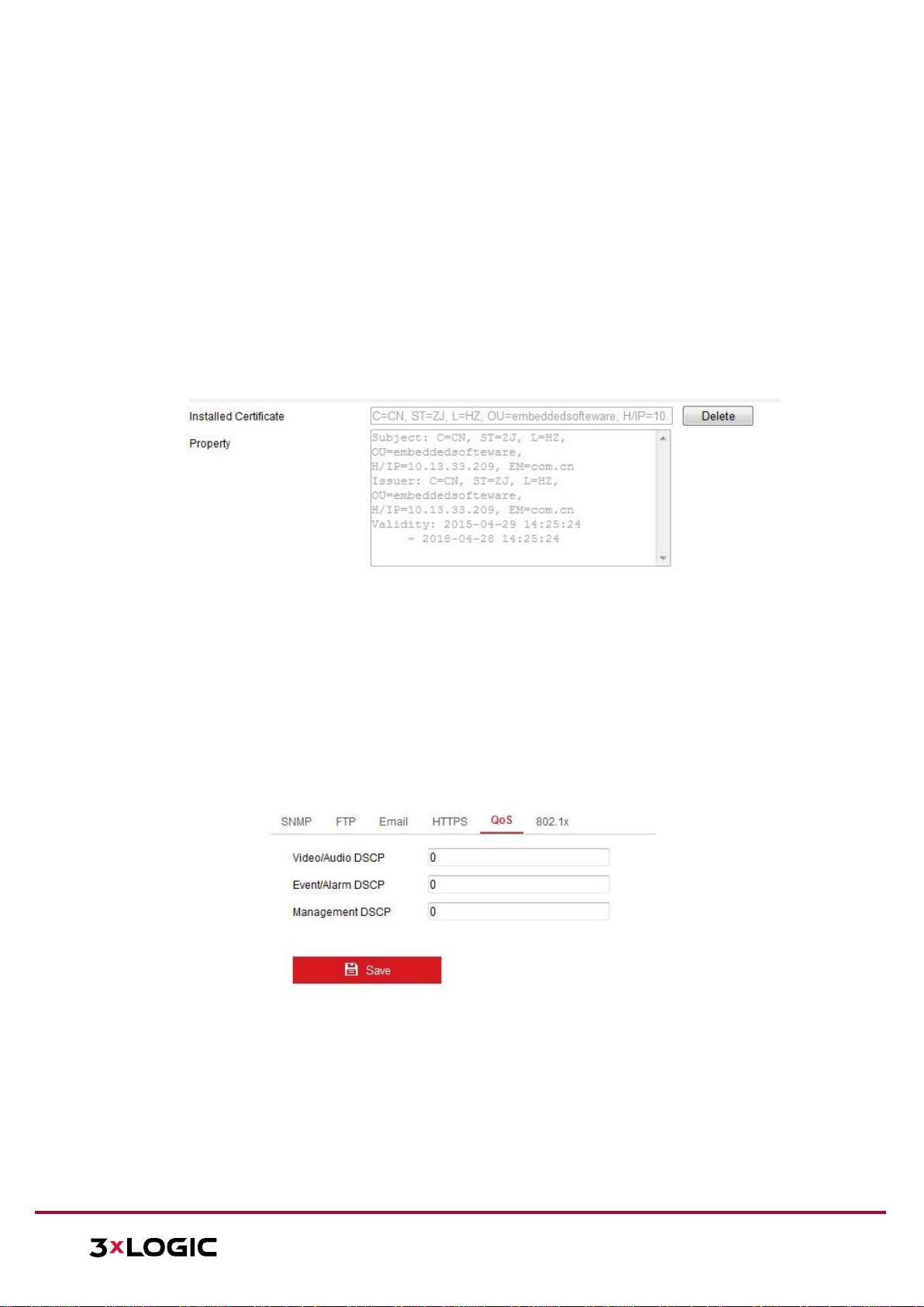
VISIX V-SERIES SOFTWARE USER MANUAL| VISIX V-Series All-in-One Camera – Gen II
12000 Pecos St., Suite 290, Westminster, CO 80234 | www.3xlogic.com | (877) 3XLOGIC
64
NOTE: If you already have a certificate installed, the Create Self-signed Certificate is grayed
out.
Create an authorized certificate
a. Select Create the certificate request first and continue the installation as the Installation
Method.
b. Click Create button to create the certificate request. Fill in the required information in the
popup window.
c. Download the certificate request and submit it to the trusted certificate authority for
signature.
d. After receiving the signed valid certificate, import the certificate to the device.
4. There will be the certificate information after successfully creating and installing the certificate.
Figure 11-14 Installed Certificate
5. Click the Save button to save the settings.
CONFIGURING QOS SETTINGS
QoS (Quality of Service) can help solve network delay and network congestion by configuring the
priority of data sending. QoS settings can be edited in this tab.
Steps:
1. Enter the QoS Settings interface: Configuration > Network > Advanced Settings > QoS
Figure 11-15 QoS Settings
2. Configure the QoS settings, including Video/Audio DSCP, Event/Alarm DSCP and Management
DSCP. The valid value range of the DSCP is 0 to 63. The bigger the DSCP value is, the higher the
priority is.
NOTE: DSCP refers to the Differentiated Service Code Point; and the DSCP value is used in the IP
header to indicate the priority of the data.
3. Click Save to save the settings.
Page 65

VISIX V-SERIES SOFTWARE USER MANUAL| VISIX V-Series All-in-One Camera – Gen II
12000 Pecos St., Suite 290, Westminster, CO 80234 | www.3xlogic.com | (877) 3XLOGIC
65
NOTE: A reboot is required for the settings to take effect.
CONFIGURING 802.1X SETTINGS
IEEE 802.1X. Settings can be configured in this section. The IEEE 802.1X standard is supported by the
network camera, and when the feature is enabled, the camera data is secured and user
authentication is needed when connecting the camera to the network protected by IEEE 802.1X.
Before you start:
The authentication server must be configured. Please apply and register a user name and password
for 802.1X in the server.
For your privacy and to better protect your system against security risks, we strongly
recommend the use of strong passwords for all functions and network devices. The password
should be something of your own choosing (using a minimum of 8 characters, including at
least three of the following categories: upper case letters, lower case letters, numbers and
special characters) in order to increase the security of your product.
Proper configuration of all passwords and other security settings is the responsibility of the
installer and/or end-user.
Steps:
1. Enter the 802.1X Settings interface: Configuration > Network > Advanced Settings > 802.1X
Figure 11-16 802.1X Settings
2. Check the Enable IEEE 802.1X checkbox to enable the feature.
3. Configure the 802.1X settings, including Protocol, EAPOL version, User Name, Password and
Confirm.
NOTE: The EAPOL version must be identical with that of the router or the switch.
4. Enter the user name and password to access the server.
5. Click Save to finish the settings.
NOTE: A reboot is required for the settings to take effect.
Page 66
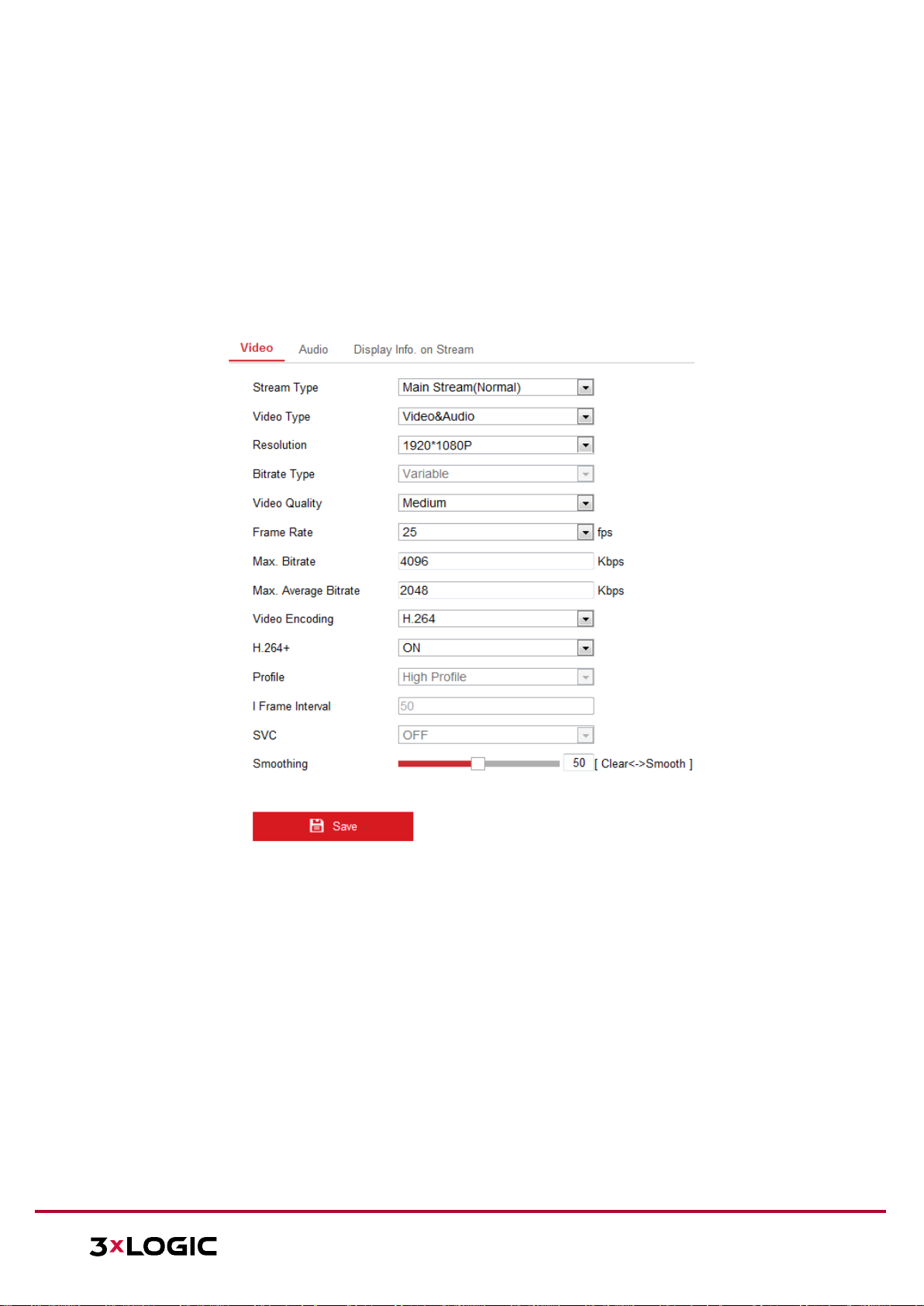
VISIX V-SERIES SOFTWARE USER MANUAL| VISIX V-Series All-in-One Camera – Gen II
12000 Pecos St., Suite 290, Westminster, CO 80234 | www.3xlogic.com | (877) 3XLOGIC
66
12 Video/Audio Settings
Follow the instructions below to configure the video settings, audio settings, ROI, and Display info. on
Stream settings.
12.1 Configuring Video Settings
Steps:
1. Enter the Video Settings interface: Configuration > Video/Audio > Video
Figure 12-1 Video Settings
2. Select the Stream Type of the camera to main stream (normal), sub-stream or third stream.
NOTES: For some models, to enable the third stream, go to System>Maintenance>System
Service> Software and check the checkbox of Enable Third Stream to reboot the system and
enable the third stream. The main stream is usually for recording and live view on networks with
abundant bandwidth and the sub-stream can be used for live view on networks where bandwidth
is limited.
5. To enable the third stream, go to System>Maintenance>System Service> Software and
check the checkbox of Enable Third Stream to reboot the system and enable the third
stream.
3. You can customize the following parameters for the selected stream type.
Video Type: Set the stream type to video stream, or video & audio composite stream. The
audio signal will be recorded only when the Video Type is Video & Audio.
Page 67

VISIX V-SERIES SOFTWARE USER MANUAL| VISIX V-Series All-in-One Camera – Gen II
12000 Pecos St., Suite 290, Westminster, CO 80234 | www.3xlogic.com | (877) 3XLOGIC
67
Resolution: Select the resolution of the video output.
Bitrate Type: Set the Bitrate Type to Constant or Variable.
Video Quality: When Bitrate Type is set as Variable, 6 levels of video quality are selectable.
Frame Rate: Set the frame rate. The frame rate describes the frequency at which the video
stream is updated and it is measured by frames per second (fps). A higher frame rate is
advantageous when there is movement in the video stream, as it maintains image quality
throughout.
Max. Bitrate: Set the max. bitrate from 32 to 16384 Kbps. Higher values correspond with
higher video quality, but more bandwidth is consumed.
NOTE: The maximum limit of the max. bitrate value varies according to different camera
platforms. For certain cameras, the maximum limit is 8192 Kbps or 12288 Kbps.
Video Encoding: If the Stream Type is set to main stream, H.264 and H.265 are selectable,
and if the stream type is set to sub stream or third stream, H.264, MJPEG, and H.265 are
selectable. H.265 is a new encoding technology. Compared with H.264, it reduces the
transmission bitrate under the same resolution, frame rate and image quality.
NOTE: Selectable video encoding types may vary according to different camera modes.
H.264+ AND H.265+:
H.264+: If you set Main Stream as the Stream Type, and H.264 as the video encoder, you can
see H.264+ available. H.264+ is an improved compression coding technology based on H.264.
By enabling H.264+, users can estimate the HDD consumption by its maximum average
bitrate. Compared to H.264, H.264+ reduces storage by up to 50% with the same maximum
bitrate in most scenes. H.264+ also allows for easy configuration of the VIGIL substream
motion detection feature.
H.265+: If you set the main stream as the stream type, and H.265 as the video encoding, you
can see H.265+ available. H.265+ is an improved compression coding technology based on
H.265. By enabling H.265+, users can estimate the HDD consumption by its maximum
average bitrate. Compared to H.265, H.265+ reduces storage by up to 50% with the same
maximum bitrate in most scenes.
NOTES:
► Upgrade your video player to the latest version if live view or playback does not
work properly due to compatibility.
► The bitrate type must be variable if you want to use H.264+ or H.265+.
► With H.264+/H.265+ enabled, the parameters such as profile, I frame interval, video
quality, and SVC are greyed out if the bitrate type is variable.
► With H.264+/H.265+ enabled, some functions are not supported. For those
functions, corresponding interfaces will be hidden.
► H.264+/H.265+ can spontaneously adjust the bitrate distribution according the
requirements of the actual scene in order to utilize the set maximum average
bitrate in the long term. The camera needs at least 3 days to adapt to a fixed
monitoring scene.
Page 68
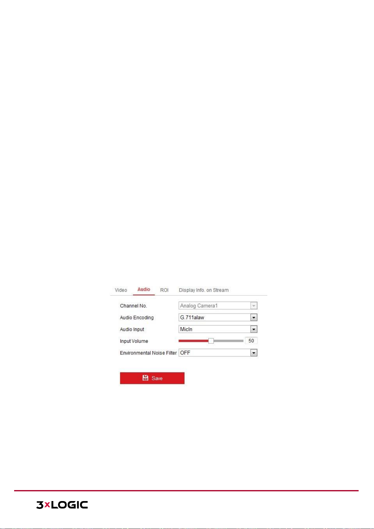
VISIX V-SERIES SOFTWARE USER MANUAL| VISIX V-Series All-in-One Camera – Gen II
12000 Pecos St., Suite 290, Westminster, CO 80234 | www.3xlogic.com | (877) 3XLOGIC
68
► You need to reboot the camera if you want to turn on or turn off the H.264+/H.265+
codec. If you switch from H.264+ to H.265+ directly, and vice versa, a reboot is not
required by the system.
Max. Average Bitrate: When you set a maximum bitrate, its corresponding recommended
maximum average bitrate will be shown in the Max. Average Bitrate box. You can also set the
maximum average bitrate manually from 32 Kbps to the value of the set maximum bitrate.
Profile: Basic profile, Main Profile, and High Profile for coding are selectable.
I Frame Interval: Set I Frame Interval from 1 to 400.
SVC: Scalable Video Coding is an extension of the H.264/AVC standard. Select OFF/ON to
disable/enable the SVC function. Select Auto and the device will automatically extract frames
from the original video when the network bandwidth is insufficient.
Smoothing: It refers to the smoothness of the stream. The higher the smoothing value, the
more fluid the stream will be, though video quality may be affected. The lower the
smoothing value, the higher quality the stream will be, though the footage may appear less
fluid.
4. Click Save to save the settings.
NOTE: Video parameters vary according to different camera models. Refer to the actual display page
for camera functions.
12.2 Configuring Audio Settings
Steps:
1. Enter the Audio Settings interface: Configuration > Video/Audio > Audio.
Figure 12-2 Audio Settings
2. Configure the following settings:
NOTE: Audio settings vary according to different camera models.
Audio Encoding: G.722.1, G.711 ulaw, G.711alaw, G.726, MP2L2 and PCM are
selectable. For MP2L2, the Sampling Rate and Audio Stream Bitrate are configurable.
For PCM, the Sampling Rate can be set.
Audio Input: MicIn and LineIn are selectable for the connected microphone and
pickup respectively.
Page 69

VISIX V-SERIES SOFTWARE USER MANUAL| VISIX V-Series All-in-One Camera – Gen II
12000 Pecos St., Suite 290, Westminster, CO 80234 | www.3xlogic.com | (877) 3XLOGIC
69
Input Volume: 0-100 adjustable.
Environmental Noise Filter: Set it as OFF or ON. When the function is enabled, the
noise in the environment can be filtered to some extent.
3. Click Save to save the settings.
12.3 Configuring ROI Encoding
ROI (Region of Interest) encoding helps to discriminate between ROI and background information in
video compression, which means the technology assigns more encoding resources to the region of
interest, thus increasing the quality of the ROI. Adversely, the background portion of the image
receives less resources.
NOTE: ROI function varies according to different camera models.
Figure 12-3 Region of Interest Settings
Steps:
1. Enter the ROI settings interface: Configuration > Video/Audio > ROI.
2. Select the Stream Type for ROI encoding.
3. Check-off Enable under Fixed Region item.
4. Set Fixed Region for ROI.
a. Select the Region No. from the drop-down list.
Page 70

VISIX V-SERIES SOFTWARE USER MANUAL| VISIX V-Series All-in-One Camera – Gen II
12000 Pecos St., Suite 290, Westminster, CO 80234 | www.3xlogic.com | (877) 3XLOGIC
70
b. Check the Enable checkbox to enable ROI function for the chosen region.
c. Click Drawing. Click and drag the mouse on the view screen to draw a red rectangle as the
ROI region. You can click Clear to cancel former drawing. Click Stop Drawing when you finish.
d. Select the ROI level.
e. Enter a region name for the chosen region.
f. Click Save the save the settings of ROI settings for chosen fixed region.
g. Repeat steps (1) to (6) to setup other fixed regions.
5. Set Dynamic Region for ROI.
a. Check the checkbox to enable Face Tracking.
NOTE: To enable face tracking function, the face detection function should be supported and
enabled.
b. Select the ROI level.
6. Click Save to save the settings.
NOTE: ROI level means the image quality enhancing level. The larger the value is, the better the image
quality will be.
12.4 Display Info. on Stream
Check-off Enable Dual-VCA to mark object information (e.g. human, vehicle, etc.) in the video stream.
After enabling, you can set rules on the connected rear-end device to detect the events including line
crossing, intrusion, etc.
Figure 12-4 Display Info. on Stream
12.5 Configuring Target Cropping
You can specify a target area on the live video stream which can be displayed via the third stream,
providing more detail of the target area if needed.
NOTE: Target cropping function varies according to different camera models.
Steps:
1. Enter the Target Cropping settings interface.
2. Check Enable Target Cropping checkbox to enable the function.
3. Set Third Stream as the stream type.
4. Select the cropping resolution for the video display of target area. A red rectangle is displayed on
the live video to mark the target area, and you can click-and-drag the rectangle to re-size the
target area as desired.
5. Click Save to save the settings.
Page 71

VISIX V-SERIES SOFTWARE USER MANUAL| VISIX V-Series All-in-One Camera – Gen II
12000 Pecos St., Suite 290, Westminster, CO 80234 | www.3xlogic.com | (877) 3XLOGIC
71
13 Image Settings
Follow the instructions in this chapter to configure the image parameters, including Display settings,
OSD settings, Privacy Mask and Picture Overlay.
13.1 Configuring Display Settings
Purpose:
Configure the image adjustment, exposure settings, day/night switch, backlight settings, white
balance, image enhancement, video adjustment, and other parameters in display settings.
NOTE: The display parameters vary according to the different camera models. Please refer to the
actual interface for details.
DAY/NIGHT AUTO-SWITCH
Steps:
1. Enter the Display Settings interface: Configuration > Image > Display Settings.
Figure 13-1 Display Settings of Day/Night Auto-Switch
2. Set the image parameters of the camera.
NOTE: In order to guarantee the image quality in different illumination environments, the camera
provides two sets of parameters for users to configure.
Image Adjustment
Brightness describes bright of the image, which ranges from 1 to 100.
Contrast describes the contrast of the image, which ranges from 1 to 100.
Saturation describes the colorfulness of the image color, which ranges from 1 to 100.
Sharpness describes the edge contrast of the image, which ranges from 1 to 100.
Page 72

VISIX V-SERIES SOFTWARE USER MANUAL| VISIX V-Series All-in-One Camera – Gen II
12000 Pecos St., Suite 290, Westminster, CO 80234 | www.3xlogic.com | (877) 3XLOGIC
72
Exposure Settings
If the camera is equipped with a fixed lens, only Manual is selectable, and the iris mode is not
configurable.
If Auto is selected, you can set the auto iris level from 0 to 100.
The Exposure Time refers to the electronic shutter time, which ranges from 1 to 1/100,000s.
Adjust it according to actual luminance conditions.
Image Gain can also be manually configured from 0 to 100. The bigger the value, the brighter
the image however, noise would also be amplified to a larger extent.
Figure 13-2 Exposure Settings
Day/Night Switch
Select the Day/Night Switch mode according to your surveillance environment. Day, Night, Auto,
Scheduled-Switch, and Triggered by alarm input are selectable for day/night switch.
Figure 13-3 Day/Night Switch
Day: Enable Day mode.
Night: Enable Night mode.
Auto: The camera switches between day mode and night mode automatically
depending on environment illumination. The sensitivity ranges from 0 to 7. The higher
the value is, the easier the mode switches. The filtering time refers to the interval time
between the day/night switch. You can set it from 5s to 120s.
Scheduled-Switch: Set the start time and the end time to define the duration for
day/night mode.
Triggered by alarm input: The switch is triggered by alarm input. You can set the
triggered mode to day or night.
Smart Supplement Light: Set the supplement light as ON, and Auto and Manual are
selectable for light mode.
► Auto: The supplemental light changes according to the actual luminance. E.g., if
the current scene is bright enough, then the supplemental light adjusts itself to
lower power; and if the scene is not bright enough, the light adjusts itself to higher
Page 73

VISIX V-SERIES SOFTWARE USER MANUAL| VISIX V-Series All-in-One Camera – Gen II
12000 Pecos St., Suite 290, Westminster, CO 80234 | www.3xlogic.com | (877) 3XLOGIC
73
power.
► Manual: Manually adjust the supplement by adjusting the distance. E.g., if the
object is near the camera, the device adjusts the supplement light to lower power,
and the light adjusts to higher power if the object is far away.
Backlight Settings
BLC Area: If you focus on an object against strong backlight, the object will be too dark
to be seen clearly. BLC compensates light to the object in the front to make it clear.
OFF, Up, Down, Left, Right, Center, Auto, and Custom are selectable.
NOTE: If BLC mode is set as Custom, you can draw a red rectangle on the live view image
to define the BLC area.
WDR: Wide Dynamic Range can be used when there is a high contrast between the
bright area and dark areas of a scene.
HLC: High Light Compression function can be used when there are strong lights in the
scene affecting the image quality.
White Balance
White balance is a function of the camera used to adjust the color temperature according to the
environment.
Figure 13-4 White Balance
Image Enhancement
Digital Noise Reduction: DNR reduces the noise in the video stream. OFF, Normal and
Expert are selectable. Set the DNR level from 0 to 100 in Normal Mode. Set the DNR level
from both space DNR level [0-100] and time DNR level [0-100] in Expert Mode.
Defog Mode: You can enable the defog function when the environment is foggy and the
image is misty. It enhances the subtle details so that the image appears clearer.
EIS (Electrical Image Stabilizer): EIS reduces the effects of vibration in a video.
Grey Scale: You can choose the range of the grey scale as [0-255] or [16-235].
Video Adjustment
Mirror: It mirrors the image so you can see it inversed. Left/Right, Up/Down, Center, and
OFF are selectable.
Rotate: To make a complete use of the 16:9 aspect ratio, you can enable the rotate
function when you use the camera in a narrow view scene.
Page 74

VISIX V-SERIES SOFTWARE USER MANUAL| VISIX V-Series All-in-One Camera – Gen II
12000 Pecos St., Suite 290, Westminster, CO 80234 | www.3xlogic.com | (877) 3XLOGIC
74
► When installing a camera to monitor a narrow scene, turn the camera 90 degrees or
rotate the 3-axis lens to 90 degrees, and set the rotate mode to on to obtain a normal
view of the scene with 9:16 aspect ratio. Use this method to help eliminate obstructions
such as walls, leading to a clearer field-of-vision.
Scene Mode: Choose the scene as indoor or outdoor according to the surveillance
environment.
Video Standard: 50 Hz and 60 Hz are selectable. Choose according to the different video
standards; normally 50 Hz for PAL standard and 60 Hz for NTSC standard.
Capture Mode: A selectable video input mode to meet field of view and requirements.
Lens Distortion Correction: For cameras equipped with motor-driven lens, image may
appear distorted to some extent. Turn on this function to correct the distortion.
Others
Some camera models support CVBS, SDI, or HDMI output. Set the local output ON or OFF
according to the actual device.
DAY/NIGHT SCHEDULED-SWITCH
The Day/Night scheduled-switch configuration interface enables you to set the camera parameters for
day and night separately, guaranteeing image quality under different illumination environments.
Figure 13-5 Day/Night Scheduled-Switch Configuration Interface
Steps:
1. Click the calendar icon to select the start time and the end time of the switch.
NOTES:
► The start time and end time refer to the valid time for Day mode.
► The time period can start and end on two days in a row. For example, if you set start time as
10:00 and end time as 1:00, the day mode will be activated at 10am in the morning and
stopped at 1am the next morning.
2. Click Common tab to configure the common parameters applicable to the day mode and night
mode.
Page 75

VISIX V-SERIES SOFTWARE USER MANUAL| VISIX V-Series All-in-One Camera – Gen II
12000 Pecos St., Suite 290, Westminster, CO 80234 | www.3xlogic.com | (877) 3XLOGIC
75
NOTE: For the detailed information of each parameter, please refer to Section 9.1.1 Day/Night
Auto-Switch.
3. Click Day tab to configure the parameters applicable for day mode.
4. Click Night tab to configure the parameters applicable for night mode.
NOTE: The settings saved automatically if any parameter is changed.
Page 76

VISIX V-SERIES SOFTWARE USER MANUAL| VISIX V-Series All-in-One Camera – Gen II
12000 Pecos St., Suite 290, Westminster, CO 80234 | www.3xlogic.com | (877) 3XLOGIC
76
13.2 Configuring OSD Settings
Purpose:
You can customize the camera name, time/date format, display mode, and OSD size displayed on the
live view.
Figure 13-6 OSD Settings
Steps:
1. Enter the OSD Settings interface: Configuration > Image > OSD Settings.
2. Check the corresponding checkbox to select the display of camera name, date or week if
required.
3. Edit the camera name in the text field of Camera Name.
4. Select from the drop-down list to set the time format and date format.
5. Select from the drop-down list to set the time format, date format, display mode, OSD size and
OSD color.
6. Configure the text overlay settings.
a. Check the checkbox in front of the textbox to enable the on-screen display.
b. Input the characters in the textbox.
NOTE: Up to 8 text overlays are configurable.
7. Adjust the position and alignment of text frames.
6. Left align, right align and custom are selectable. If you select custom, you can use the
mouse to click and drag text frames in the live view window to adjust their positions.
Page 77

VISIX V-SERIES SOFTWARE USER MANUAL| VISIX V-Series All-in-One Camera – Gen II
12000 Pecos St., Suite 290, Westminster, CO 80234 | www.3xlogic.com | (877) 3XLOGIC
77
NOTE: The alignment adjustment is only applicable to Text Overlay items.
8. Click Save to save the settings.
Page 78

VISIX V-SERIES SOFTWARE USER MANUAL| VISIX V-Series All-in-One Camera – Gen II
12000 Pecos St., Suite 290, Westminster, CO 80234 | www.3xlogic.com | (877) 3XLOGIC
78
13.3 Configuring Privacy Mask
Purpose:
Privacy mask enables you to cover certain areas on the live video to obscure portions of the video
from appearing in live view or recorded playback footage.
Steps:
1. Enter the Privacy Mask Settings interface: Configuration > Image > Privacy Mask.
2. Check off the Enable Privacy Mask checkbox to enable this function.
3. Click Draw Area.
Figure 13-7 Privacy Mask Settings
4. Click and drag the mouse in the live video window to draw the mask area.
NOTE: You are allowed to draw up to 4 areas on the same image.
5. Click Stop Drawing to finish drawing or click Clear All to clear all of the areas you set without
saving them.
6. Click Save to save the settings.
13.4 Configuring Picture Overlay
Purpose:
Picture overlay enables you to overlay a picture on the image. This function enables users to overlay a
company logo on the image.
Steps:
1. Enter the Picture Overlay Settings interface: Configuration > Image > Picture Overlay.
Page 79

VISIX V-SERIES SOFTWARE USER MANUAL| VISIX V-Series All-in-One Camera – Gen II
12000 Pecos St., Suite 290, Westminster, CO 80234 | www.3xlogic.com | (877) 3XLOGIC
79
Figure 13-8 Picture Overlay
2. Click Browse to select a picture.
3. Click Upload to upload the image.
4. Check Enable Picture Overlay checkbox to enable the function.
5. Set X Coordinate and Y Coordinate values to adjust the picture position on the image. Adjust
Picture Width and Picture Height to the desired size.
6. Click Save to save settings.
NOTE: The picture must be in RGB24 bmp format and the maximum picture size is 128x128.
Page 80

VISIX V-SERIES SOFTWARE USER MANUAL| VISIX V-Series All-in-One Camera – Gen II
12000 Pecos St., Suite 290, Westminster, CO 80234 | www.3xlogic.com | (877) 3XLOGIC
80
14 Event Settings
This section explains how to configure the network camera to respond to alarm events, including
Basic Events and Smart Events.
14.1 Basic Events
You can configure basic events by following the instructions in this section, including Motion
Detection, Video Tampering, Alarm Input, Alarm Output, and Exception, etc. These events can trigger
the linkage methods, such as Notify Surveillance Center, Send Email, Trigger Alarm Output, etc.
NOTE: Check the checkbox of Notify Surveillance Center if you want the alarm information to be
pushed to PC or mobile client software as soon as the alarm is triggered.
CONFIGURING MOTION DETECTION
Purpose:
Motion detection detects object movement in the configured surveillance area, and a series of actions
can be taken when the alarm is triggered.
In order to detect the moving objects accurately and reduce the false alarm rate, normal
configuration and expert configuration are selectable for different motion detection environments.
Normal Configuration
Normal configuration adopts the same set of motion detection parameters in the daytime and at
night.
Tasks 1: Set the Motion Detection Area
Steps:
1. Enter the motion detection settings interface: Configuration > Event > Basic Event > Motion
Detection.
2. Check the Enable Motion Detection checkbox.
3. Check the Enable Dynamic Analysis for Motion checkbox if you want to mark the detected objects
with green tracking rectangles.
NOTE: Select Disable for rules if you don’t want the detected objected displayed with the green
rectangles. Select disable rules from Configuration > Local Configuration > Live View Parametersrules.
Page 81
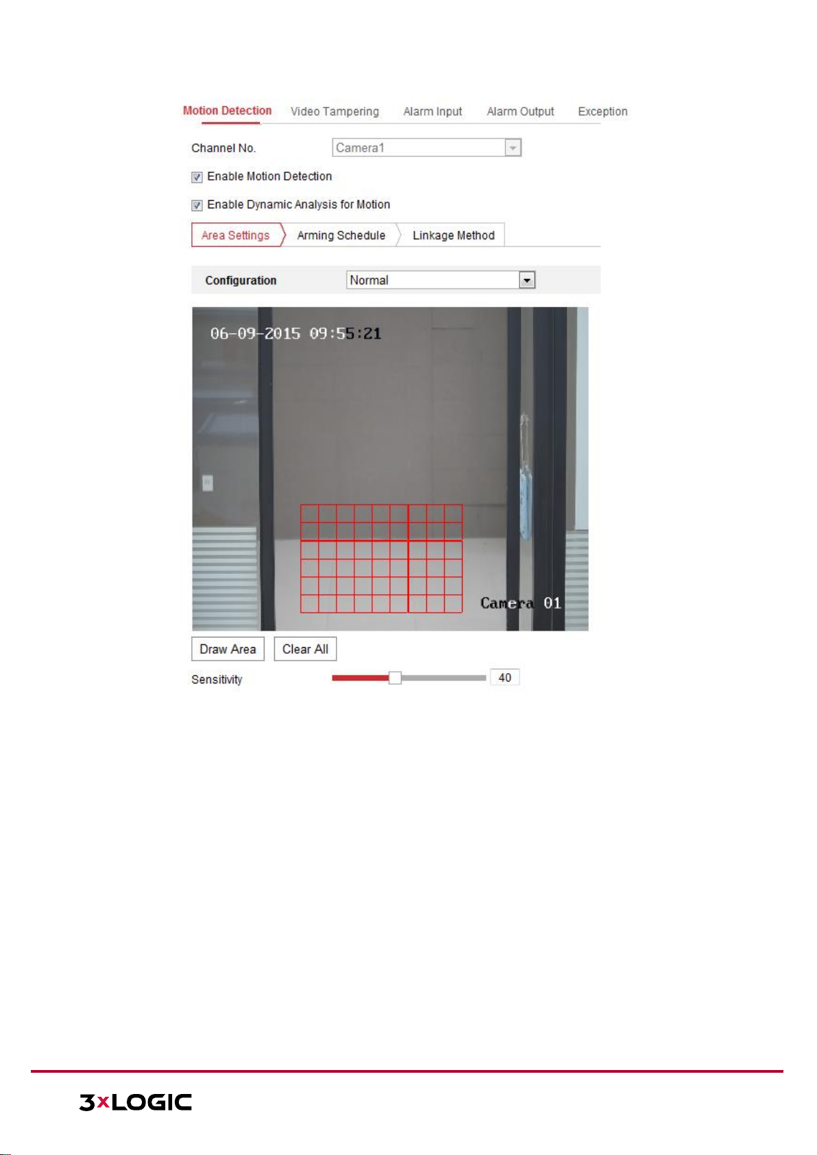
VISIX V-SERIES SOFTWARE USER MANUAL| VISIX V-Series All-in-One Camera – Gen II
12000 Pecos St., Suite 290, Westminster, CO 80234 | www.3xlogic.com | (877) 3XLOGIC
81
Figure 14-1 Enable Motion Detection
4. Click Draw Area. Click and drag the mouse on the live video to draw a motion detection area. Click
Stop Drawing to finish drawing one area.
5. (Optional) Click Clear All to clear all of the areas.
6. (Optional) Move the slider to set the detection sensitivity.
Page 82

VISIX V-SERIES SOFTWARE USER MANUAL| VISIX V-Series All-in-One Camera – Gen II
12000 Pecos St., Suite 290, Westminster, CO 80234 | www.3xlogic.com | (877) 3XLOGIC
82
Task 2: Set the Arming Schedule for Motion Detection
Figure 14-2 Arming Schedule
Steps:
1. Click Arming Schedule to edit the arming schedule.
2. Click on the time bar and drag the mouse to select the time period.
Figure 14-3 Arming Schedule
NOTE: Click on the selected time period, you can adjust the time period to the desired time by
either moving the time bar or inputting the exact time period.
3. (Optional) Click Delete to delete the current arming schedule, or click Save to save the settings.
4. Move the mouse to the end of each day, a copy dialogue box pops up, and you can copy the
current settings to other days.
5. Click Save to save the settings.
NOTE: Time periods cannot be overlapped. Up to 8 periods can be configured for each day.
Page 83

VISIX V-SERIES SOFTWARE USER MANUAL| VISIX V-Series All-in-One Camera – Gen II
12000 Pecos St., Suite 290, Westminster, CO 80234 | www.3xlogic.com | (877) 3XLOGIC
83
Task 3: Set the Linkage Method for Motion Detection
Check the checkbox to select a corresponding linkage method. Audible Warning, Send Email, Notify
Surveillance Center, Upload to FTP/Memory Card/NAS, Trigger Channel and Trigger Alarm Output are
selectable. You can specify the linkage method when an event occurs.
Figure 14-4 Linkage Method
NOTE: The linkage methods vary according to the different camera models.
Audible Warning: Trigger the audible warning locally. Audible warnings are only supported by
devices with audio output.
Notify Surveillance Center: Send an exception or alarm signal to remote management
software when an event occurs.
Send Email: Send an email with alarm information to a user or users when an event occurs.
NOTE: To send the Email when an event occurs, please refer to Section 7.2.3 to complete
Email setup in advance.
Upload to FTP/Memory Card/NAS: Capture the image when an alarm is triggered and upload
the picture to a FTP server.
NOTES:
► Set the FTP address and the remote FTP server first. Refer to Section 7.2.2 Configuring
FTP Settings for detailed information.
► Go to the Configuration > Storage > Schedule Settings> Capture > Capture Parameters
page, enable the event-triggered snapshot, and set the capture interval and capture
number.
► The captured image can also be uploaded to the available SD card or network disk.
Trigger Channel: The video will be recorded when motion is detected. You have to set the
recording schedule to utilize this function. Please refer to Section 13 for detailed information.
Trigger Alarm Output: Trigger one or more external alarm outputs when an event occurs.
NOTE: To trigger an alarm output when an event occurs, please refer to Section 12.1 –
Configuring Alarm Output to set the related parameters.
Expert Configuration
Expert mode is mainly used to configure the sensitivity and proportion of an object in each area for
both day/night mode switching.
Page 84

VISIX V-SERIES SOFTWARE USER MANUAL| VISIX V-Series All-in-One Camera – Gen II
12000 Pecos St., Suite 290, Westminster, CO 80234 | www.3xlogic.com | (877) 3XLOGIC
84
Figure 14-5 Expert Mode of Motion Detection
Day/Night Switch OFF:
Steps:
1. Draw the detection area as in normal configuration mode. Up to 8 areas are supported.
2. Select OFF for Switch Day and Night Settings.
3. Select the area by clicking the area No.
4. Slide the cursor to adjust the sensitivity and proportion of object on the area for the selected area.
5. Set the arming schedule and linkage method as in the normal configuration mode.
6. Click Save to save the settings.
Day/Night Auto-Switch:
Steps:
1. Draw the detection area as in normal configuration mode. Up to 8 areas are supported.
2. Select Auto-Switch for Switch Day and Night Settings.
3. Select the area by clicking the area No.
4. Slide the cursor to adjust the sensitivity and proportion of object on the area for the selected
area in the daytime.
5. Slide the cursor to adjust the sensitivity and proportion of object on the area for the selected
area at night.
6. Set the arming schedule and linkage method as in the normal configuration mode.
7. Click Save to save the settings.
Day/Night Scheduled-Switch:
Steps:
1. Draw the detection area as in the normal configuration mode. Up to 8 areas are supported.
2. Select Scheduled-Switch for Switch Day and Night Settings.
Page 85

VISIX V-SERIES SOFTWARE USER MANUAL| VISIX V-Series All-in-One Camera – Gen II
12000 Pecos St., Suite 290, Westminster, CO 80234 | www.3xlogic.com | (877) 3XLOGIC
85
Figure 14-6 Day/Night Scheduled-Switch
3. Select the start time and the end time for the switch timing.
4. Select the area by clicking the area No.
5. Slide the cursor to adjust the sensitivity and proportion for objects in the area during daytime.
6. Slide the cursor to adjust the sensitivity and proportion for objects in the area during night.
7. Set the arming schedule and linkage method as in normal configuration mode.
8. Click Save to save the settings.
CONFIGURING VIDEO TAMPERING ALARM
Purpose:
You can configure the camera to trigger an alarm when the lens is covered/obscured and also
configure certain alarm response actions when tampering is detected.
Steps:
1. Enter the video tampering Settings interface, Configuration > Event > Basic Event > Video
Tampering.
Figure 14-7 Video Tampering Alarm
Page 86

VISIX V-SERIES SOFTWARE USER MANUAL| VISIX V-Series All-in-One Camera – Gen II
12000 Pecos St., Suite 290, Westminster, CO 80234 | www.3xlogic.com | (877) 3XLOGIC
86
2. Check Enable Video Tampering checkbox to enable the video tampering detection.
3. Set the video tampering area. Refer to Task 1: Set the Motion Detection Area in Section 12. 1 –
Configuring Motion Detection
4. Click Edit to edit the arming schedule for video tampering. The arming schedule configuration is
the same process as setting the arming schedule for motion detection. Refer to Task 2: Set the
Arming Schedule for Motion Detection in Section 12.1 – Configuring Motion Detection
5. Check the checkbox to select the linkage method taken for the video tampering. Audible warning,
notify surveillance center, send email and trigger alarm output are selectable. Please refer to Task
3: Set the Linkage Method for Motion Detection in Section 12.1 – Configuring Motion Detection
6. Click Save to save the settings.
CONFIGURING ALARM INPUT
Steps:
1. Enter the Alarm Input Settings interface: Configuration > Event > Basic Event > Alarm Input.
2. Choose the alarm input No. and the Alarm Type. The alarm type can be NO (Normally Open) and
NC (Normally Closed). Edit the name to set a name for the alarm input (optional).
Figure 14-8 Alarm Input Settings
3. Click Arming Schedule to set the arming schedule for the alarm input. Refer to Task 2: Set the
Arming Schedule for Motion Detection in Section 12. 1 – Configuring Motion Detection
4. Click Linkage Method and check the checkbox to select the linkage method taken for the alarm
input. Refer to Task 3: Set the Linkage Method for Motion Detection in Section 12.1– Configuring
Motion Detection
5. You can copy your settings to other alarm inputs.
6. Click Save to save the settings.
Page 87

VISIX V-SERIES SOFTWARE USER MANUAL| VISIX V-Series All-in-One Camera – Gen II
12000 Pecos St., Suite 290, Westminster, CO 80234 | www.3xlogic.com | (877) 3XLOGIC
87
CONFIGURING ALARM OUTPUT
Figure 14-9 Alarm Output Settings
Steps:
1. Enter the Alarm Output Settings interface: Configuration> Event > Basic Event > Alarm Output.
2. Select one alarm output channel in the Alarm Output drop-down list. You can also set a name for
the alarm output (optional).
3. The Delay time can be set to 5sec, 10sec, 30sec, 1min, 2min, 5min, 10min or Manual. The delay
time refers to the time duration that the alarm output remains in effect after alarm occurs.
4. Click Arming Schedule to enter the Edit Schedule Time interface. The time schedule configuration
is the same as setting the arming schedule for motion detection. Refer to Task 2: Set the Arming
Schedule for Motion Detection in Section 12.1 – Configuring Motion Detection
5. You can copy the settings to other alarm outputs.
6. Click Save to save the settings.
HANDLING EXCEPTION
The exception type can be HDD full, HDD error, network disconnected, IP address conflicted and
illegal login to the cameras.
Steps:
1. Enter the Exception Settings interface: Configuration > Event > Basic Event > Exception.
2. Check the checkbox to set the actions taken for the Exception alarm. Refer to Task 3: Set the
Linkage Method for Motion Detection in Section 12. 1 – Configuring Motion Detection
Page 88

VISIX V-SERIES SOFTWARE USER MANUAL| VISIX V-Series All-in-One Camera – Gen II
12000 Pecos St., Suite 290, Westminster, CO 80234 | www.3xlogic.com | (877) 3XLOGIC
88
Figure 14-10 Exception Settings
3. Click Save to save the settings.
CONFIGURING OTHER ALARM
NOTE: Some cameras support Wireless Alarm, PIR (passive infrared sensor) Alarm or Emergency
Alarm.
Wireless Alarm
When a wireless alarm signal is sent to the camera from the detector, such as the wireless door
contact, the wireless alarm is triggered and a series of response actions can be taken.
Steps:
1. Enter the Wireless Alarm Settings interface:
Configuration > Advanced Configuration> Basic Event > Wireless Alarm
Figure 14-11 Setting Wireless Alarm
2. Select the wireless alarm number.
Up to 8 channels of external wireless alarm input are supported.
3. Check the checkbox of Enable Wireless Alarm to activate the wireless alarm.
4. Input the alarm name in the text field as desired.
5. Check the checkbox to select the linkage methods taken for the wireless alarm.
6. Click Save to save the settings.
7. Locate the external wireless device beside the camera, and go to Configuration > System > System
Settings > Remote Control to arm the camera and analyze the wireless alarm.
Figure 14-12 Configuring Wireless Alarm Settings
Page 89

VISIX V-SERIES SOFTWARE USER MANUAL| VISIX V-Series All-in-One Camera – Gen II
12000 Pecos St., Suite 290, Westminster, CO 80234 | www.3xlogic.com | (877) 3XLOGIC
89
PIR Alarm
A PIR (Passive Infrared) alarm is triggered when an intruder moves within the detector's field of view.
The heat energy dissipated by a person, or any other warm blooded animals such as dogs, cats, etc.,
can be detected.
Steps:
1. Enter the PIR Alarm Settings interface:
Configuration > Advanced Configuration> Basic Event> PIR Alarm
Figure 14-13 Setting PIR Alarm
2. Check the Enable checkbox to activate the PIR alarm function.
3. Input the alarm name in the text field as desired.
4. Check off appropriate linkage methods for the PIR alarm.
5. Click the Edit button to set the arming schedule.
6. Click Save to save the settings.
7. Go to Configuration > Advanced Configuration> System> Remote Control to arm the camera.
Figure 14-14 Arming PIR Alarm
Emergency Alarm
You can press the Emergency button on the remote control to trigger the Emergency Alarm.
Page 90

VISIX V-SERIES SOFTWARE USER MANUAL| VISIX V-Series All-in-One Camera – Gen II
12000 Pecos St., Suite 290, Westminster, CO 80234 | www.3xlogic.com | (877) 3XLOGIC
90
NOTE: The remote control is required for the Emergency Alarm.
Steps:
1. Enter the Emergency Alarm Settings interface:
Configuration > Event > Basic Event> Emergency Alarm
Figure 14-15 Setting Emergency Alarm
2. Check off the appropriate linkage methods for the Emergency alarm.
3. Click Save to save the settings.
Page 91

VISIX V-SERIES SOFTWARE USER MANUAL| VISIX V-Series All-in-One Camera – Gen II
12000 Pecos St., Suite 290, Westminster, CO 80234 | www.3xlogic.com | (877) 3XLOGIC
91
15 Storage Settings
Before you start:
To configure recording settings, please make sure that you have the network storage device or local storage
device configured.
15.1 Configuring Record Schedule
Purpose:
There are two kinds of recording for the camera: manual recording and scheduled recording. In this section,
you can follow the instructions to configure scheduled recording. By default, files recorded via scheduled
recording are stored in the local storage (on-board SD Card).
Steps:
1. Enter the Record Schedule Settings interface: Configuration > Storage > Schedule Settings > Record Schedule.
Figure 15-1 Recording Schedule Interface
2. Check off Enable to enable scheduled recording.
3. Click Advanced to set the camera recording parameters.
Figure 15-2 Record Parameters
Pre-record: The time you set to start recording before the scheduled time or event. For example, if an
alarm triggers recording at 10:00, and the pre-record time is set as 5 seconds, the camera starts to
record at 9:59:55. The Pre-record time can be configured as No Pre-record, 5s, 10s, 15s, 20s, 25s, 30s
or not limited.
Page 92

VISIX V-SERIES SOFTWARE USER MANUAL| VISIX V-Series All-in-One Camera – Gen II
12000 Pecos St., Suite 290, Westminster, CO 80234 | www.3xlogic.com | (877) 3XLOGIC
92
Post-record: The time you set to stop recording after the scheduled time or the event. For example, if
an alarm triggered recording ends at 11:00, and the post-record time is set as 5 seconds, the camera
records until 11:00:05. The Post-record time can be configured as 5s, 10s, 30s, 1 min, 2 min, 5 min or
10 min.
Stream Type: Select the stream type for recording.
NOTE: The record parameter configurations vary depending on the camera model.
4. Select a Record Type. The record type can be Continuous, Motion Detection, Alarm, Motion | Alarm, Motion
& Alarm, and Event.
Continuous: If you select Continuous, the video will be recorded automatically according to the time
of the schedule.
Record Triggered by Motion Detection: If you select Motion Detection, the video will be recorded
when motion is detected. Besides configuring the recording schedule, you must also set the motion
detection area and enable a Trigger Channel in the Linkage Method of the Motion Detection Settings
interface. For detailed information, please refer to the Task 1: Set the Motion Detection Area in the
Section 12.1
Record Triggered by Alarm: If you select Alarm, the video will be recorded when the alarm is triggered
via the external alarm input channels.
Besides configuring the recording schedule, you must also set the Alarm Type and enable a Trigger
Channel in the Linkage Method of Alarm Input Settings interface. For detailed information, please
refer to Section 12.1
Record Triggered by Motion & Alarm: If you select Motion & Alarm, the video will be recorded when
motion is detected and an alarm are triggered at the same time.
Besides configuring the recording schedule, you must also configure the settings on the Motion
Detection and Alarm Input Settings interfaces. Please refer to Section 12.1 for detailed information.
Record Triggered by Motion | Alarm: If you select Motion | Alarm, the video will be recorded when
the external alarm is triggered or if motion is detected.
Besides configuring the recording schedule, you must also configure the settings in the Motion
Detection and Alarm Input Settings interfaces. Please refer to Section 12.1 for detailed information.
Record Triggered by Events: If you select Event, the video will be recorded if any configured events are
triggered. Besides configuring the recording schedule, you must also configure the event settings.
5. Select the record type, and click-and-drag the mouse on the time bar to set the record schedule.
6. Click Save to save the settings.
15.2 Configure Capture Schedule
Purpose:
You can configure the scheduled snapshot and event-triggered snapshot settings in this section. Captured
stillshots/pictures can be stored in the local storage or network storage.
Steps:
1. Enter the Capture Settings interface: Configuration > Storage > Storage Settings > Capture.
Page 93

VISIX V-SERIES SOFTWARE USER MANUAL| VISIX V-Series All-in-One Camera – Gen II
12000 Pecos St., Suite 290, Westminster, CO 80234 | www.3xlogic.com | (877) 3XLOGIC
93
Figure 15-3 Capture Configuration
2. Go to the Capture Schedule tab to configure the capture schedule by clicking and dragging the mouse on
the time bar. You can copy the record schedule to other days by clicking the green copy icon on the right
of each time bar.
3. Click Advanced to select a stream type.
Figure 15-4 Advanced Setting of Capture Schedule
4. Click Save to save the settings.
5. Go to the Capture Parameters tab to configure the capture parameters.
a. Check the Enable Timing Snapshot checkbox to enable continuous snapshot.
b. Select the picture format, resolution, quality and capture interval of continuous snapshots.
c. Check the Enable Event-triggered Snapshot checkbox to enable event-triggered snapshots.
d. Select the picture format, resolution, quality, capture interval, and capture number of event-triggered
snapshots.
Page 94

VISIX V-SERIES SOFTWARE USER MANUAL| VISIX V-Series All-in-One Camera – Gen II
12000 Pecos St., Suite 290, Westminster, CO 80234 | www.3xlogic.com | (877) 3XLOGIC
94
Figure 15-5 Set Capture Parameters
6. Set the time interval between two snapshots.
7. Click Save to save the settings.
15.3 Configuring Net HDD
Before you start:
Network drives should be available on the camera’s host network and properly configured to store recorded
files, log files, pictures, etc.
Steps:
1. Add Net HDD.
a. Enter the Net HDD settings interface: Configuration > Storage > Storage Management > Net HDD.
Figure 15-6 Add Network Disk
b. Enter the IP address of the network disk, and enter the file path.
Page 95

VISIX V-SERIES SOFTWARE USER MANUAL| VISIX V-Series All-in-One Camera – Gen II
12000 Pecos St., Suite 290, Westminster, CO 80234 | www.3xlogic.com | (877) 3XLOGIC
95
c. Select the mounting type. NFS and SMB/CIFS are selectable. You can set a user name and password
to strengthen security if SMB/CIFS is selected (highly recommended).
7. NOTE: Please refer to the NAS User Manual for creating the file path.
For your privacy and to better protect your system against security risks, we strongly
recommend the use of strong passwords for all functions and network devices. The password
should be something of your own choosing (using a minimum of 8 characters, including at
least three of the following categories: upper case letters, lower case letters, numbers and
special characters) in order to increase the security of your product.
Proper configuration of all passwords and other security settings is the responsibility of the
installer and/or end-user.
d. Click Save to add the network drive.
2. Initialize the added network drive.
a. Enter the HDD Settings interface: Configuration > Storage > Storage Management > HDD
Management. From here, you can view the capacity, free space, status, type and property of the drive.
Figure 15-7 Storage Management Interface
b. If the status of the drive is Uninitialized, check the corresponding checkbox to select the drive and
click Format to start initializing the disk.
Note: When the initialization completed, the status of the drive will become Normal.
Figure 15-8 View Disk Status
3. Define the quota for recorded footage and pictures.
a. Input the quota percentage for pictures and for recorded footage.
b. Click Save and refresh the browser page to activate the settings.
Page 96

VISIX V-SERIES SOFTWARE USER MANUAL| VISIX V-Series All-in-One Camera – Gen II
12000 Pecos St., Suite 290, Westminster, CO 80234 | www.3xlogic.com | (877) 3XLOGIC
96
Figure 15-9 Quota Settings
NOTE: Up to 8 NAS disks can be connected to the camera.
15.4 Memory Card Detection
With Memory Card Detection, you can view the memory card’s status, lock your memory card, and receive
notification when an issue is detected with the memory card.
NOTE: Memory card detection function is only supported by certain types of memory cards and camera
models. If this tab page is not visible in the camera’s Web UI, it means either that your camera does not
support the function, or your installed memory card is not supported for this function. You can contact the
dealer or the retailer for information on supported camera and memory card models.
Steps:
1. Enter the Memory Card Detection configuration interface:
Configuration > Storage > Storage Management > Memory Card Detection
Figure 15-10 Memory Card Detection
2. View the memory card status on Status Detection tab.
Remaining Lifespan: Displays percentage of the remaining lifespan. The lifespan of a memory
card may be influenced by factors such as its capacity and bitrate. You need to change the
memory card if the remaining lifespan is insufficient.
Health Status: Displays the condition of your memory card. There are three status descriptions,
good, bad, and damaged. You will receive a notification if the health status is anything other
than good when the Arming Schedule and Linkage Method are set.
NOTE: It is recommended that you change the memory card when the health status displays any
other status than “Good”.
3. Click the R/W Lock tab to add a lock to the memory card. With the R/W lock added, the memory card’s read
and write capabilities can only be used when it is unlocked.
Page 97

VISIX V-SERIES SOFTWARE USER MANUAL| VISIX V-Series All-in-One Camera – Gen II
12000 Pecos St., Suite 290, Westminster, CO 80234 | www.3xlogic.com | (877) 3XLOGIC
97
Figure 15-11 R/W Lock Setting
Add a Lock
a. Select the Lock Switch as ON.
b. Input the password.
c. Click Save to save the settings.
Unlock
a. If you use the memory card on the camera configured to lock the card, unlocking will be done
automatically and no unlocking procedures are required on the part of the user.
b. If you use the memory card (with a lock) on a different camera, you can go to the HDD Management
interface to unlock the memory card. Select the memory card, click the Unlock button shown next to
the Format button. Input the correct password to unlock the memory card.
NOTES:
► The memory card’s read and write capabilities can only be used when unlocked.
► If the camera is restored to the factory settings while the card is locked, you can go to the HDD
Management interface to unlock the memory card.
Remove the Lock
a. Select the Lock Switch as OFF.
b. Input the correct password in the Password Settings text field.
c. Click Save to save the settings.
4. Set the Arming Schedule and Linkage Method if you want to receive a notification when the memory card’s
health status is switched from “Good”. Refer to Task 2: Set the Arming Schedule for Motion Detection and
Task 3: Set the Linkage Method for Motion Detection in Section 12.1.
5. Click Save to save the settings.
15.5 Configuring Lite Storage
When there is no moving object detected in a scene being recorded by the camera, the frame rate and bitrate
of the video stream can be reduced to reduce storage usage on the memory card.
NOTES:
► Lite storage function varies according to different camera models.
► The video files recorded in lite storage mode will be played back in full frame rate (25fps/30fps), and
thus the playback speed appears faster than normal.
1. Enter the Lite Storage interface:
Configuration > Storage > Storage Management > Lite Storage
2. Check off Enable to enable the lite storage function.
3. Input the storage time in the text field. You can view the memory card’s available storage capacity on the
page.
4. Click Save to save the settings.
Page 98

VISIX V-SERIES SOFTWARE USER MANUAL| VISIX V-Series All-in-One Camera – Gen II
12000 Pecos St., Suite 290, Westminster, CO 80234 | www.3xlogic.com | (877) 3XLOGIC
98
16 Open Platform Settings
The Open Platform settings interface contains information and configurable settings pertaining to the device’s
3xLOGIC VIGIL Software, deployment site and camera status. Advanced Camera settings commonly associated
with site setup can also be accessed from this interface.
16.1 Application
From the Application interface, a user can manually import and apply the latest VIGIL Server software package.
If the camera was setup using one of 3xLOGIC’s available Setup Tools (See Section 3), the latest VIGIL Software
will have been automatically applied.
Figure 16-1 Application Settings Interface
UPDATING VIGIL SOFTWARE
Steps:
Navigate to the Application Interface: Configuration>Open Platform > Application.
1. Click the Browse button next to the Application Packages field. A file explorer will deploy.
2. Navigate to the location of the VIGIL Software package using the file explorer, select the file and
click Open.
3. Click the Import button. The software should now automatically apply and begin running.
4. Click the Start button (located under the Status table) to confirm the software is running. A pop-up
will deploy in the bottom-right corner of the window to prompt the user if the software is already
running.
5. (Optional) Click the Log button to open an update log (text file) in a separate browser window.
16.2 3xLOGIC
From the 3xLOGIC settings interface, a user can view and configure information related to camera’s status,
deployment site and maintenance settings. Advanced settings commonly accessed during camera deployment
are also available for configuration.
If the camera was setup using one of 3xLOGIC’s available Setup Tools (See Section 3), these settings will have
been auto-configured to their recommended state.
STATUS
From the Status tab, a user can view general Camera Information, Camera Status information and Storage
Status information.
Page 99

VISIX V-SERIES SOFTWARE USER MANUAL| VISIX V-Series All-in-One Camera – Gen II
12000 Pecos St., Suite 290, Westminster, CO 80234 | www.3xlogic.com | (877) 3XLOGIC
99
Figure 16-2 3xLOGIC - Status Interface
SITE INFORMATION
From the Site Information tab, a user can configure settings related to the camera’s site setup. Configurable
settings are Company Name, Site Name, Camera Name, VIGIL Connect Alias and VIGIL Data Port.
Figure 16-3 3xLOGIC – Site Information Interface
Site Information
Company Name – The name of the company which purchased and deployed the camera.
Page 100

VISIX V-SERIES SOFTWARE USER MANUAL| VISIX V-Series All-in-One Camera – Gen II
12000 Pecos St., Suite 290, Westminster, CO 80234 | www.3xlogic.com | (877) 3XLOGIC
100
Site Name – The Site Name associated with the camera. In VIGIL Client, the camera will be located
under the site name in the left-side treeview.
Camera Name – The Name of the camera. This will be used to identify the camera within VIGIL VMS
Utilities.
VIGIL Connect Alias – The camera’s VIGIL Connect Alias. VIGIL Connect allows a user to easily
connect to a VIGIL Server / All-in-One Camera from other VIGIL utilities without network connection
information (IP, port, etc…), requiring only the alias and a valid username and password for the
target device.
After changing settings, click Apply to save the new configuration.
Port Information
VIGIL Data Port – The VIGIL Data Port. 22801 is the default value.
After changing the port number, click Apply to save the new value.
MAINTENANCE
From the 3xLOGIC – Maintenance interface, a user can reboot the camera or set the camera’s Recording
Configuration.
Figure 16-4 3xLOGIC – Maintenance Interface
Click the Reboot button to reboot the camera.
Select a Recording Configuration from the drop-down menu and click Apply to save the new
configuration.
ADVANCED SETTINGS
From the Advanced Settings interface a user can manually adjust advanced settings commonly accessed during
camera deployment.
 Loading...