

X62w
Multimedia Projector
Network Functions
This manual is only intended to explain Network Functions.
WARNING
and related manuals to ensure proper use of this product. After reading them,
store them in a safe place for future reference.
NOTE
• The manufacturer assumes no responsibility for any errors that may appear in
this manual.
• The reproduction, transfer or copy of all or any part of this document is not
permitted without express written consent.
Trademark acknowledgment
• Windows is a registered trademark of Microsoft Corporation.
All other trademarks are the properties of their respective owners.
• The information in this manual is subject to change without notice.
►Before using this product, read the “Product Safety Guide”
1

Contents
Contents
Contents
Caution …………………………………………………………………………………… 3
1. Main Functions ……………………………………………………………………… 5
1.1 Live Mode (Project images from PC) ………………………………………… 5
1.2 PC-LESS Presentation
(Display the images stored in SD card/USB memory.) …………………… 6
2. Equipment connection and network setting …………………………… 8
2.1 Required equipment preparation ……………………………………………… 8
2.2 Network connection using “One-Click-Communication” function ……… 8
2.3 Manual network connection setting – Wired LAN - ……………………… 10
2.3.1 Equipments connection …………………………………………………… 10
2.3.2 Network settings …………………………………………………………… 11
2.3.3 “Internet Option” setting ………………………………………………… 14
2.3.4 Check connection …………………………………………………………… 15
2.4 Manual network connection setting – For wireless LAN - ……………… 16
2.4.1 Preparation for wireless LAN connection ……………………………… 16
2.4.2 Wireless LAN connection set up ………………………………………… 17
2.5 Confi guring and Controlling the projector via a web browser …………… 19
2.5.1 Network Information ……………………………………………………… 22
2.5.2 Network Settings …………………………………………………………… 23
2.5.3 Port Settings ………………………………………………………………… 25
2.5.4 Mail Settings ………………………………………………………………… 26
2.5.5 Alert Settings ………………………………………………………………… 27
2.5.6 Schedule Settings…………………………………………………………… 32
2.5.7 Date/Time Settings ………………………………………………………… 34
2.5.8 Security Settings …………………………………………………………… 36
2.5.9 Projector Control …………………………………………………………… 38
2.5.10 Projector Status …………………………………………………………… 41
2.5.11 Network Restart …………………………………………………………… 41
2.5.12 Logoff………………………………………………………………………… 41
2.6 Utilize Web Remote Control …………………………………………………… 42
3. How to use Projector software – Basics - ………………………………… 44
3.1 How to use “MIU Live Viewer” ………………………………………………… 44
3.1.1 Install “MIU Live Viewer” ………………………………………………… 44
3.1.2 Software Installation Procedure ………………………………………… 45
3.1.3 Explanation of “MIU Live Viewer” ……………………………………… 46
3.1.4 Utilize “MIU Live Viewer” – Basic - ……………………………………… 50
3.2 Utilize “PC-LESS Presentation” – Basic - …………………………………… 52
4. Utilize projector – Advanced - ………………………………………………… 54
4.1 Utilize “MIU Live Viewer” – Advanced - ……………………………………… 54
4.1.1
4.2 Utilize “PC-LESS Presentation” – Advanced - ……………………………… 56
Connect multiple PCs with one projector (Multiple PCs connection)
4.2.1 Thumbnail display ………………………………………………………… 57
4.2.2 Display in full screen ……………………………………………………… 59
4.2.3 Slide show …………………………………………………………………… 61
4.2.4 Directory display …………………………………………………………… 63
4.2.5 “PC-LESS Presentation” error message ……………………………… 66
4.3 Playlist ……………………………………………………………………………… 67
4.4 Failure & Warning Alerts via E-mail …………………………………………… 68
4.5 Projector management via SNMP ……………………………………………… 70
4.6 Controlling the Projector via Scheduling …………………………………… 71
4.7 e-SHOT (Still Image Transfer) Display………………………………………… 74
4.8 Command Control via the Network …………………………………………… 75
5. Troubleshooting …………………………………………………………………… 80
6. Specifi cations ……………………………………………………………………… 82
7. Warranty and After-sales service …………………………………………… 83
…54
2

Caution
Caution
Caution
[Restriction in terms of inserts or pulls memory card and wireless LAN card]
Do not pull out the memory card and the wireless card while the power is on. The
memory card can be pulled out only while the card access LED (Red) is off.
CAUTION
The accompanying 802.11g wireless LAN card uses the 2.4GHz radio frequency band. You
do not need a radio license to use this card, but you should be aware of the following:
DO NOT USE NEAR THE FOLLOWING!
• Microwave ovens
• Industrial, scientific or medical devices
• Designated low power radio stations
• Premises radio stations
Using the wireless LAN card near the above may result in radio interference, which in
turn may result in a decrease in communication speed and even a complete loss of
communication.
Depending on the location where you attempt to use the wireless LAN card, there may be
interference with the radio waves, which may result in a decrease in communication speed
and even a complete loss of communication. In particular, please be aware that using the
wireless LAN card in locations where there is reinforced steel, other metals and concrete
may interfere with radio communication.
Available Channels
The wireless LAN card uses the 2.4GHz radio frequency band, but depending on the
country or region you are in, you might be limited to the channels you can use. Please
refer to the following table for confirming where and with what channels you may use the
accompanying 802.11g wireless LAN card. Please consult with your dealer for countries
not included in the table.
Country or Region Available Channel
Japan 1 to 11
USA 1 to 11
Taiwan 1 to 11
Canada 1 to 11
UK, Spain, Germany, Italy, Austria, Switzerland,
Belgium, Sweden, Netherlands, Portugal,
Denmark, Finland, Greece, Norway, France,
Ireland, Luxembourg, Iceland
You may not bring the wireless LAN card into countries not listed above as there is
a possibility that use of the wireless LAN card in those countries could lead to an
infringement of established radio laws.
1 to 11
3

4
1. Main functions
1. Main functions
1. Main functions
1.1
Live Mode
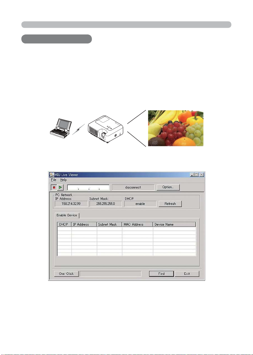
The main function of MIU (Multi Information processing Unit) is the Live Mode.
On Live Mode, the projector displays the screen appearing on the PC via network,
supported by “MIU Live Viewer” (Fig.1.1.a).
The “MIU Live Viewer” captures PC screen image using dedicated fi rmware
“MIU Live Viewer” and sends it to projector through wired LAN or wireless LAN
connection. (Refer to section 3 and 5 in detail.)
Fig. 1.1.a “MIU Live Viewer” outlines (through wireless LAN connection)
(Project images from PC
)
Fig. 1.1.b “MIU Live Viewer”
One projector can be connected with up to 4 PCs using “MIU Live Viewer”.
(Refer to section 4.1 in detail.)
5
1. Main functions
1.2 PC-LESS Presentation
(Display the images stored in SD card/USB memory.)
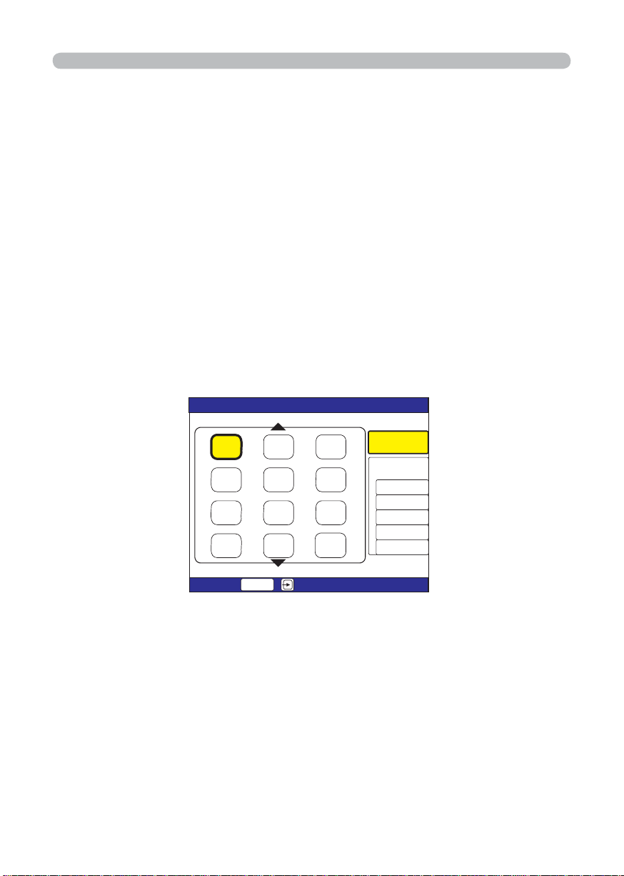
Other main function is “PC-LESS Presentation”. (Fig. 1.2.a) “PC-LESS
Presentation” has 4 kinds of display modes.
1) Thumbnail display: Display many stored images in SD card and USB memory
at once. (From now on, it is called “memory card” as SD card and USB memory
combined.)
2) Display in full screen: Display 1 picture or moving picture in full screen.
3) Slide show: Switch images with set intervals.
4) Directory display: Display directories and fi les stored in memory card as listed.
[Supported memory cards]
- SD card
- USB memory (USB memory type, USB Hard Disk and USB card
reader type)
6*7/$0#+.=5&?
㪈㪉㪊
+OCIG
+OCIG
+OCIG
+OCIG
;'5
㪌㪍㪋
㪏㪐㪎
㪈㪈 㪈㪉㪈㪇
'06'4
+OCIG
+OCIG
+OCIG
+OCIG
+OCIG
+OCIG
+OCIG
+OCIG
2%.'55
24'5'06#6+10
/'07
5.+&'5*19
56#46
5612
+06'48#.5
/1&'
10'6+/'
2.#;
Fig. 1.2.a “PC-LESS Presentation” outlines
“PC-LESS Presentation” can be controlled via keypad on the Projector or IR
Remote (refer 4.2 Utilize PC-LESS Presentation -Advanced).
You can also use “Remote Control” as shown in fi g. 1.2.b, which enables selecting
images, switching pages and switching display modes. “Remote Control” also
switches mode between “MIU Live Viewer” and “PC-LESS Presentation”.
6
1. Main functions
1.2 PC-LESS Presentation
(Display the images stored in SD card/USB memory.) (Continued)
Fig. 1.2.b Remote Control
NOTE
• There are following limitations for fi le name and directory name in
PC-LESS Presentation.
(1) The projector's language setting is Japanese.
Only alpha-numeric characters and Japanese are supported.
(2) The projector's language setting is not Japanese.
Only alpha-numeric characters and Latin-1 characters are supported.
• Data cannot be read correctly depending on the type of USB hard disk, USB
memory and USB card reader.
• When your USB hard disk can use a DC power supply adapter, please use it.
7

2. Equipment connection and network setting
2. Equipment connection and network setting
2. Equipment connection and network setting
2.1 Required equipment preparation
Followings are required for 1 projector and 1 PC connection. Multiple PC
connection is described in section 4.1.
Projector: 1 unit
PC: 1 set (“MIU Live Viewer” installation is required for “MIU Live Viewer” usage.)
IEEE802.g wireless LAN equipment is required.
Depending on the type of wireless LAN card and PC you are using, the
projector may not be able to communicate properly with your PC, even
if the PC you are using is equipped with built-in wireless LAN function.
To eliminate communication problems, please procure a Wi-Fi certifi ed
wireless LAN card.
LAN cable (in case of wired connection): 1 piece * 1
SD Wireless Network Card (in case of wireless connection): 1 unit * 2
Memory card (in case of “PC-LESS Presentation” usage): 1 piece
* 1: When a projector and a PC are connected, use CAT-5 LAN cable.
* 2: Access point is required when wireless LAN connection is used as
Infrastructure mode.
2.2 Network connection using “One-Click-Communication”
function
This section explains how to connect network using “One-Click-Communication”
function. This function makes PC and projector network connection very easy
without complicated settings like IP address and SSID.
* This function cannot be used when multiple PCs or multiple projectors are
connected.
* The system of Windows2000 Professional Service Pack 4 or Windows XP and
the administrator authority are required to use “One-Click-Communication”
function. (Administrator authority)
* This function might not work depending on your used wireless LAN driver.
If so, setup the connection manually. (
your PC and wireless equipment.)
[Wired LAN connection]
1) When projector network settings such as IP address and subnet mask are
changed, need to return to the projector factory default Network settings.
q Press the menu button on remote control or the ▲/◄/►/▼ button on keypad.
Then OSD menu will be displayed. If Easy Menu is displayed, change the
menu to Advanced menu.
8
10, 16 and refer to the User Manuals for
2. Equipment connection and network setting
2.2 Network connection using “One-Click-Communication” function
(Continued)
wSelect the MIU menu by using ▲/▼ button.
/'07=4)$?
2+%674'
+/#)'
+0276
5'672
5%4''0
126+10
/+7
'#5;/'07
.+8'/1&'
2%.'5524'5'06#6+10
5'672
G5*16
+0(14/#6+10
5'48+%'
5'.'%6
ePress the Reset key on remote control. Then Reset Menu will be displayed.
/+7
4'5'6
%#0%'.
rPress the ▲ button to reset the Network settings.
NOTE
• If you like to set these items, please set again from WEB (
• SSID, WEP KEY will be set to factory default settings.
19).
2) Connect PC and projector using LAN cable to make it ready for communication.
* In case of connecting with existing network, contact your network administrator.
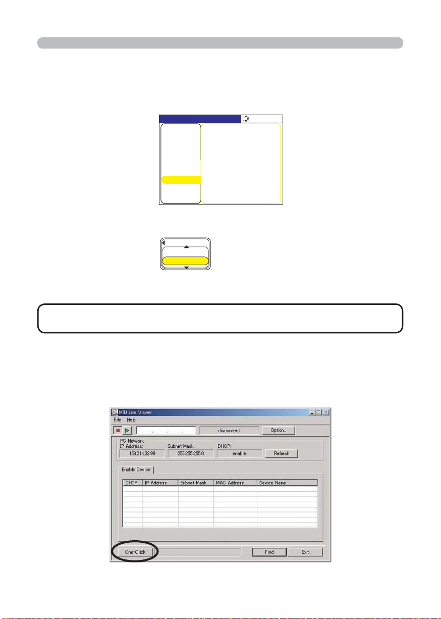
3) Start up “MIU Live Viewer”. Window appears in fi g. 2.2.a. (Refer to section 3.1
how to use “MIU Live Viewer”.)
Fig. 2.2.a “MIU Live Viewer” initial window
9

2. Equipment connection and network setting
2.2 Network connection using “One-Click-Communication” function
(Continued)
4) Click “One-Click” button in fi g. 2.2.a. Projector is found. Then capture start
button
is pushed and real time display is started automatically.
[Wireless LAN connection]
1) When projector network settings such as IP address and subnet mask are
changed, need to return to the projector factory default settings. (
9)
2) In case 802.11b/g wireless LAN device is built-in the PC, make the LAN valid
and other network connections invalid. If wireless LAN device is not built in the
PC, connect 802.11b/g wireless LAN device and install device driver to the PC.
(Refer to the user guide for wireless LAN device details.)
3) Start up “MIU Live Viewer”, then the window appears (shown in fi g. 2.2.a).
4) Click “One-Click” button as shown in fi g. 2.2.a. Then projector will be found
and the capture start button is activated then real time display is started
automatically.
2.3 Manual network connection setting – Wired LAN -
When you need to set the original IP address and SSID other than factory default
settings, need to set up network connection manually.
This section explains how to set up network connection manually.
2.3.1. Equipments connection
At fi rst, connecting projector and PC with wired LAN connection to check PC
setting and connection. Next section explains PC settings.
Connecting projector with network using LAN cable, and then set it ready to
communicate with PC.
* Connecting with existing network, contact network administrator.
At last, turn on the projector. This is the end of Equipments connection.
10
2. Equipment connection and network setting
2.3 Manual network connection setting – In case of wired LAN - (Continued)
2.3.2. Network settings
This is the explanation of network connection settings for Windows XP and
Internet Explorer.
1) Log on to Windows XP as administrator authority. (*)
2) Open “Control Panel” from “Start” menu.
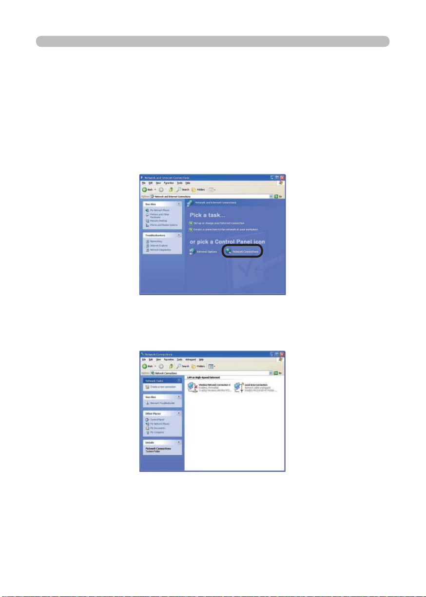
3) Open “Network and Internet Connections” in “Control Panel”. (Fig. 2.3.2.a)
* Administrator authority is the account, which can access to all functions.
Fig. 2.3.2.a “Network and Internet Connections” window
4) Open “Network Connections”. (Fig. 2.3.2.b)
Fig. 2.3.2.b “Network Connections” window
11
2. Equipment connection and network setting
2.3 Manual network connection setting – In case of wired LAN - (Continued)
5) When more than 2 usable network devices exist, make only one device “valid”
that you want to use and the rest of devices “invalid”. (In this case, “Local Area
Connection” is selected.)
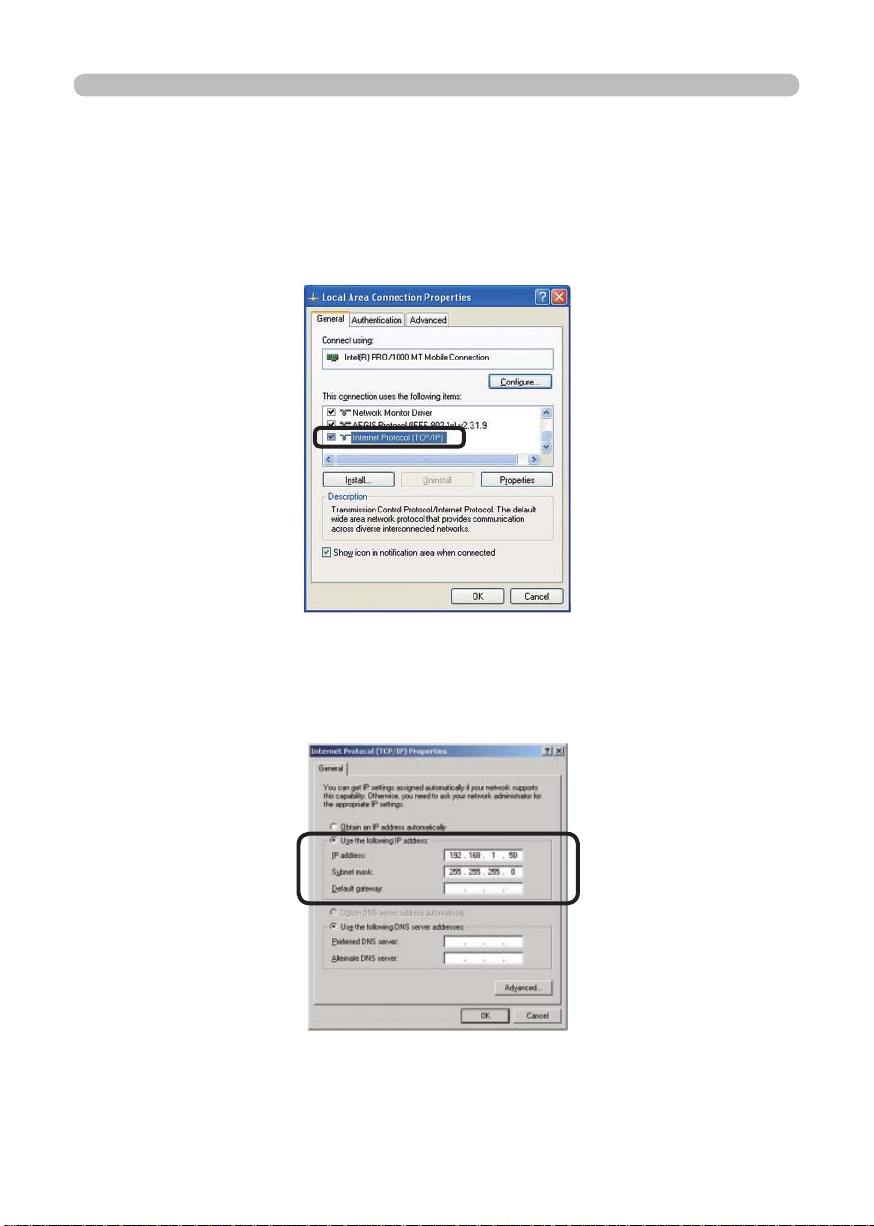
6) Open “Local Area Connection Properties” window you use for network device.
(Fig. 2.3.2.c)
Fig. 2.3.2.c “Local Area Connection Properties” window
7) Set used protocol as “TCP/IP” and open “Internet Protocol (TCP/IP) Properties”
window.
Fig. 2.3.2.d “Internet Protocol (TCP/IP) Properties” window
8) Set IP address, subnet mask and default gateway for PC.
12

2. Equipment connection and network setting
2.3 Manual network connection setting – In case of wired LAN - (Continued)
[About IP address]
Network address portion of PC IP address should be common with projector’s
one but the PC total IP address should not be overlapped with other networked
equipments.
For example, projector initial settings are as follows.
IP address: 192.168.1.10
Subnet mask: 255.255.255.0
Therefore, specify PC IP address as follows.
IP address: 192.168.1.xxx (xxx shows decimal number.)
Subnet mask: 255.255.255.0
Select from 1 to 254 for “xxx” not duplicating with any other equipments. In this
case, projector has “192.168.1.10” IP address, specify from 1 to 254 except 10 for
PC.
Projector IP address can be changed by using confi guration utility. (Refer to
section 2.5.)
When DHCP server exists in network, it is possible to set using IP address, which
is automatically assigned to projector.
If projector and PC exist in the same network (i.e. network address is common),
default gateway can be blank.
* DHCP is abbreviation for “Dynamic Host Confi guration Protocol” and the function
to provide necessary setting for network like IP address from server to client.
Server that has DHCP function is called DHCP server.
* When projector and PC exist in different networks, default gateway setting is
necessary. Contact network administrator in detail.
13
2. Equipment connection and network setting
2.3 Manual network connection setting – In case of wired LAN - (Continued)
2.3.3 “Internet Option” setting
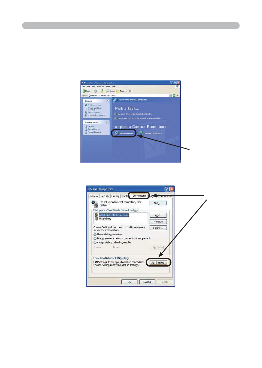
1) Click “Internet Options” in “Network and Internet Connections” window
(Fig. 2.3.3.a) to open “Internet Properties” window. (Fig. 2.3.3.b)
Click
Fig. 2.3.3.a “Network and Internet Connections” window
Click
Fig. 2.3.3.b “Internet Properties” window
2) Click “Connections” tab and then click “LAN settings” button to open “Local
Area Network (LAN) settings”. (Fig. 2.3.3.c)
14
2. Equipment connection and network setting
2.3 Manual network connection setting – In case of wired LAN - (Continued)
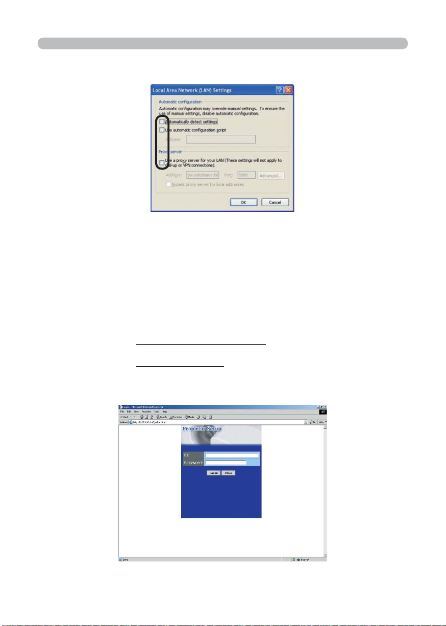
Fig. 2.3.3.c “Local Area Network (LAN) Settings” window
3) Uncheck all boxes in “Local Area Network (LAN) Settings” window. (Fig. 2.3.3.c)
2.3.4 Check connection
Check PC and projector are connected properly here. If it is not connected, check
cable connections and settings are properly or not.
1) Start browser in PC and specify following URL, then click “Go” button.
URL: http://(Projector IP address) /
For example, if projector IP address is 192.168.1.10, specify
URL: http://192.168.1.10/
2) After enter your ID and password, if Fig. 2.3.4 appears, it succeeds.
Fig. 2.3.4 “Logon Menu”
15
2. Equipment connection and network setting
2.4 Manual network connection setting – For wireless LAN
By installing SD-Link11g card, PC and wireless LAN are able to communicate in
both Ad-Hoc and Infrastructure modes.
How to set up wireless LAN connection manually.
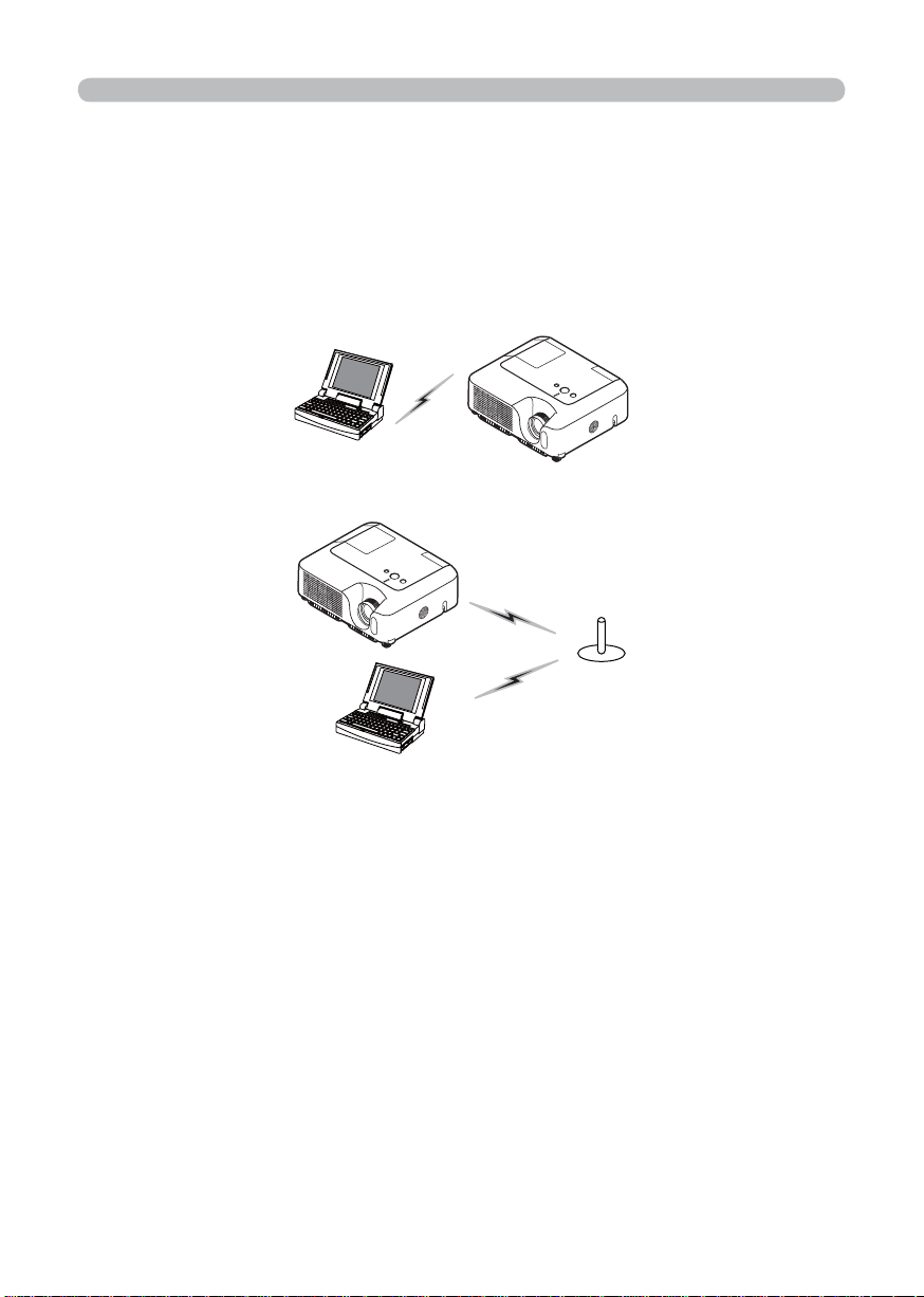
2.4.1 Preparation for wireless LAN connection
Fig. 2.4.1.a Without access point communication (Ad-Hoc)
Fig. 2.4.1.b With access point communication (Infrastructure)
* Ad-Hoc is one of the wireless LAN communication methods without having
access point to communicate.
* Infrastructure is one of the wireless LAN communication methods with having
access point to communicate. If certain quantities of equipments are used, this
mode is effi ciently.
If communicating with existing network, contact your network administrator.
First, insert the SD wireless network card into SD Card slot (
Inserting an SD card
and USB memory of the Operator's Guide).
Then, make PC ready for wireless communication.
In case 802.11b/g wireless LAN device is built-in the PC, make it valid and make
other network connections invalid. If wireless LAN device is not built-in the PC,
connect 802.11b/g wireless LAN device and install device driver. (Refer to the
user guide for PC and wireless LAN device for detail.)
16
2. Equipment connection and network setting
2.4
Manual network connection setting – For wireless LAN (Continued)
2.4.2 Wireless LAN connection set up
Using wireless LAN utility for Windows XP standard.
Wireless LAN initial settings for the projector is as follows.
Connection Control : Ad-Hoc
SSID : wireless
Channel : 1ch
Encryption rating : None
Communication speed : AUTO
IP address : 192.168.1.10
* You can change these settings as you want. Use confi guration utility or menu to
change. (Refer to section 2.5)
1) Open ”Network Connections”. (Fig. 2.4.2.a)
Fig. 2.4.2.a “Network Connections”
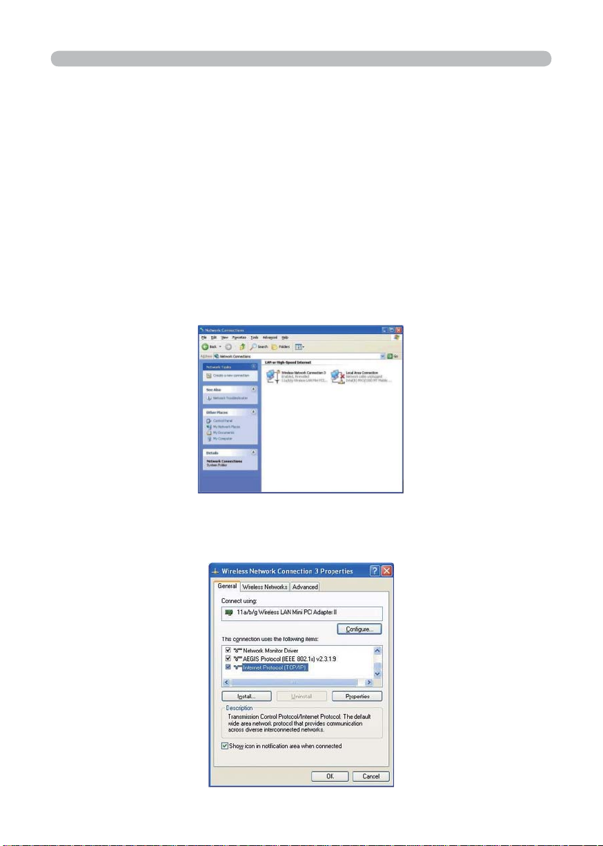
2) Make wireless network connection “Valid” and other network devices “Invalid”.
3) Open “Wireless Network Connection Properties”. (Fig. 2.4.2.b)
Fig. 2.4.2.b “Wireless Network Connection Properties” window (1)
17
2. Equipment connection and network setting
2.4
Manual network connection setting – For wireless LAN (Continued)
4) Set used protocol as “TCP/IP” and open TCP/IP property. Set IP address and
other settings as same as wired LAN connection set up. (
12)
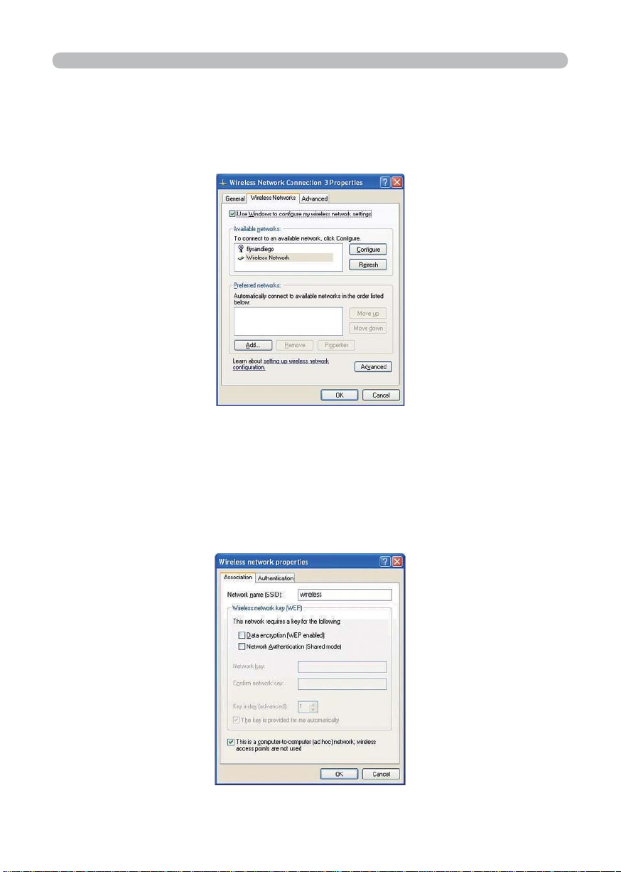
5) Open “Wireless Networks” tab. (Fig. 2.4.2.c)
Fig. 2.4.2.c “Wireless Network Connection Properties” window (2)
6) Add check mark for “Use Windows to confi gure my wireless network settings”
in “Wireless Network Connection Properties” window.
7) Click “Add” button in “Preferred networks” section in “Wireless Network
Connection Properties” window (Fig. 2.4.2.c) to open “Wireless Network
Properties” window. (Fig. 2.4.2.d)
18
Fig. 2.4.2.d “Wireless network Properties” window

2. Equipment connection and network setting
2.4
Manual network connection setting – For wireless LAN (Continued)
8) Set each item as follows.
Network name (SSID): wireless
Data encryption: Invalid (Default setting is invalid.)
* This explanation meets the projector default setting. If access point is used or
data encryption is used, if needs to change settings properly. Refer to PC or
wireless LAN device user guide for detailed information.
* If using the existing network via access point, contact your network administrator.
2.5
Confi guring and controlling the projector via a web browser
You can adjust or control the projector via a network from a web browser on a PC
that is connected to the same network.
NOTE
• If JavaScript is disabled in your web browser confi guration, you must enable
JavaScript in order to use the projector web pages properly. See the Help fi les
for your web browser for details on how to enable JavaScript.
• If no operations are performed via a web browser for approx. 50 seconds the
system will automatically log off. Please Re-log on to continue operations via a
web browser.
• After you logon, a small, blank window will appear behind the main operation
window. Please do not close this small, blank window. If this window is closed,
the system will automatically log off after certain period of time even if an
operation is being performed.
The small, blank window will close when the main operation window is closed.
• The small, blank window may be considered a pop-up and be blocked if you
are using Windows XP Service Pack 2, or using other security software.
If Service Pack 2 blocks the window the following message will appear:
"Pop-up blocked. To see this pop-up or additional options click here..."
Please select "Temporarily Allow Pop-ups" or "Always Allow Pop-ups From This
Site..." to allow the window to open.
• It is recommended that all web browser updates be installed. It is especially
recommended that all users running Internet Explorer on a Microsoft Windows
version prior to Windows XP Service Pack 2 install security update Q832894
(MS04-004) or the web browser interface may not be displayed correctly.
And when using an older version of Internet Explorer, during operations the
browser will log out after 50 seconds.
• Internet Explorer 5.5 or higher are required.
19

2. Equipment connection and network setting
2.5 Confi guring and controlling the projector via a web browser (Continued)
When confi guring or controlling the projector via a web browser, an ID and
password are required. There are two types of IDs, Administrator IDs and User
IDs. The following chart describes the differences between user and administrator
IDs.
Item Description
Network Information
Network Settings
Port Settings
Mail Settings
Alert Settings
Schedule Settings
Date/Time Settings
Security Settings
Projector Control Controls the projector. √√
Remote Control Controls the projector like IR remote. √√
Projector Status
Network Restart
Displays the projector’s current
network confi guration settings.
Displays and confi gures network
settings.
Displays and confi gures
communication port settings.
Displays and confi gures e-mail
addressing settings.
Displays and confi gures failure &
warning alerts.
Displays and confi gures schedule
settings.
Displays and confi gures the date and
time settings.
Displays and confi gures passwords
and other security settings.
Displays and confi gures the current
projector status.
Restarts the projector’s network
connection.
Administrator ID
√√
√ N/A
√ N/A
√ N/A
√ N/A
√ N/A
√ N/A
√ N/A
√√
√ N/A
User ID
Below are the factory default settings for administrator IDs, user IDs and
passwords.
Item ID Password
Administrator ID Administrator <blank>
User ID User <blank>
20
2. Equipment connection and network setting
2.5 Confi guring and controlling the projector via a web browser (Continued)
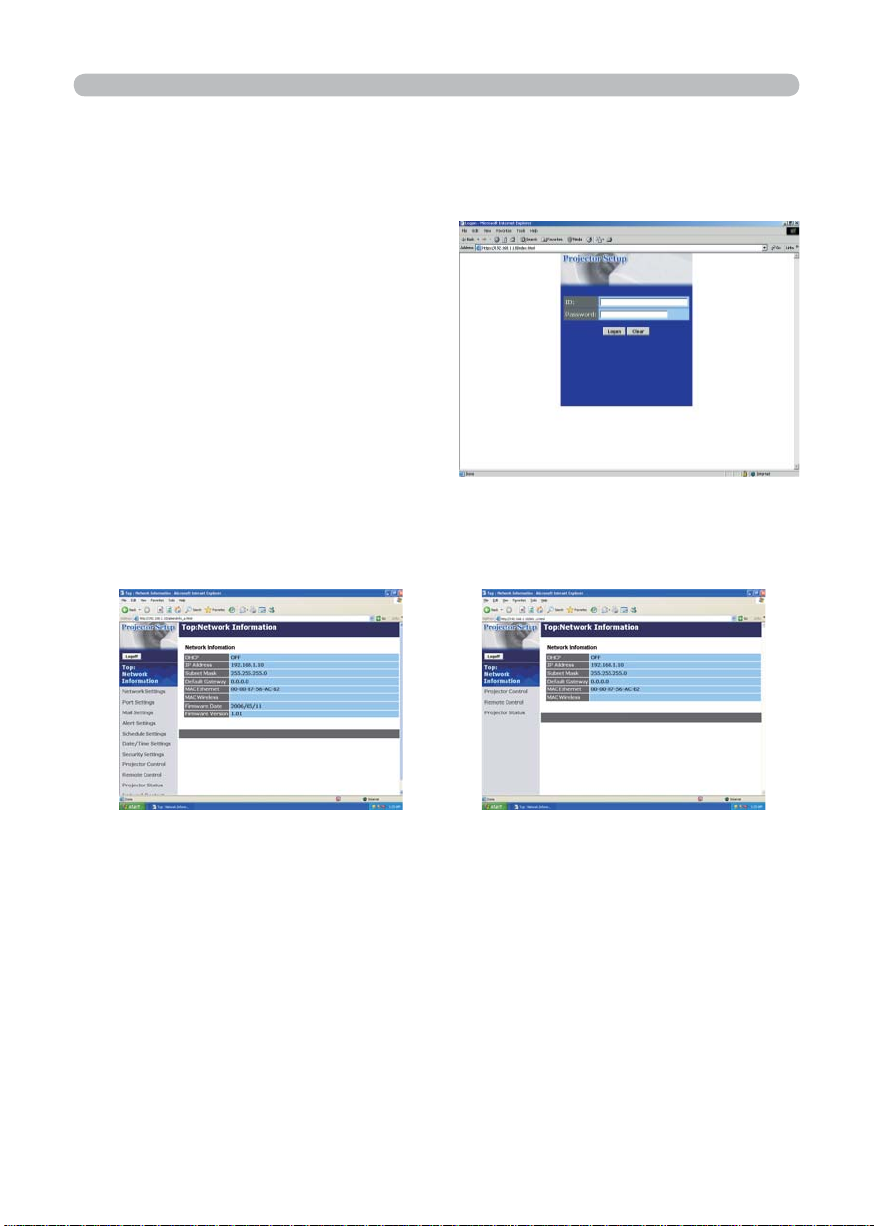
Refer to the following for confi guring or controlling the projector via a web browser.
Example: If the IP address of the projector is set to 192.168.1.10:
1) Enter
[http://192.168.1.10/] into the address
bar of the web browser and the screen
in Fig. 2.5.a will be displayed.
2) Enter your ID and password and click
[Logon] .
Fig. 2.5.a "Logon Menu"
If the logon is successful either the Fig.2.5.b or Fig.2.5.c screen will be displayed.
Fig. 2.5.b "Logon with administrator ID" Fig. 2.5.c "Logon with user ID"
3) Click the desired operation or confi guration item on the main menu located on
the left-hand side of the screen (Fig. 2.5.b or Fig. 2.5.c).
21
2. Equipment connection and network setting
2.5 Confi guring and controlling the projector via a web browser (Continued)
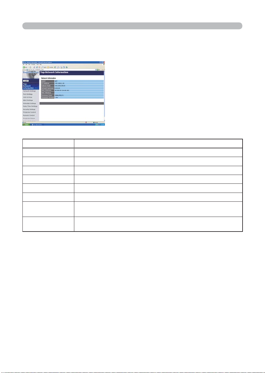
2.5.1 Network Information
All screen images displayed in this manual are
screens of a logon using an administrator ID.
Any administrator only functions will not be
displayed when using a user ID. Refer to the
descriptions in each table.
Displays the projector’s current network confi guration settings.
Item Description
DHCP Displays the DHCP confi guration settings.
IP Address Displays the current IP address.
Subnet Mask Displays the Subnet Mask.
Default Gateway Displays the Default Gateway.
MAC Ethernet Displays the Ethernet MAC address.
MAC Wireless Displays the Wireless LAN MAC address.
Firmware Date
Firmware Version
Displays the network fi rmware time stamp. This information is only
displayed when logged on using an administrator ID.
Displays the network fi rmware version number. This information is
only displayed when logged on using an administrator ID.
22
2. Equipment connection and network setting
2.5 Confi guring and controlling the projector via a web browser (Continued)
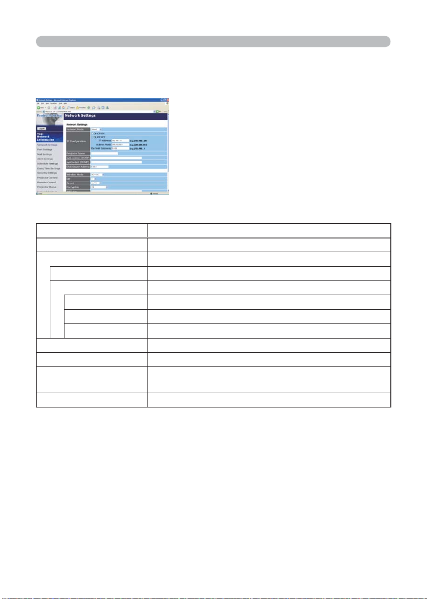
2.5.2 Network Settings
Displays and confi gures network settings.
Item Description
NETWORK MODE Select Network mode "wired" or "wireless".
IP Confi guration Confi gures network settings.
DHCP ON Enables DHCP.
DHCP OFF Disables DHCP.
IP Address Confi gures the IP address when DHCP is disabled.
Subnet Mask Confi gures the Subnet Mask when DHCP is disabled.
Default Gateway Confi gures the Default Gateway when DHCP is disabled.
Projector Name Confi gures the Projector name.
SysLocation (SNMP) Confi gures the location to be referred to when using SNMP.
SysContact (SNMP)
DNS Server Address Confi gures the DNS Server address.
Confi gures the contact information to be referred to when
using SNMP.
23
2. Equipment connection and network setting
2.5 Confi guring and controlling the projector via a web browser (Continued)
2.5.2 Network Settings (Continued)
Item Description
Wireless Mode Select "AD-HOC" or "Infrastructure".
Select using channel between "1" and "11".
CH
(Communication
channel)
Speed
(Communication speed)
Encryption Select data encryption method.
WEP Key
WPA Passphrase
SSID
NOTE
the channels may vary. In addition, depending on the
country or region where you are may be required to use
a wireless LAN card that confi rm to the standards in the
respective country or region.
Select communication speed.
Input WEP key, which has same length defi ned by WEP.
When "64bit" or "128bit" is selected, input 10 characters or
26 characters respectively. Only numbers from "0" to "9" and
alphabets from "a" to "f" can be used.
Input WPA Passphrase. Available number of input characters
is 8 to 63. Only alphabets, numbers and following symbols
can be used.
!"#$%&'()*+,-./[¥]^_`{|}~
Set SSID. Maximum number of input characters is 32. Only
alphabets, numbers and following symbols can be used.
!"#$%&'()*+,-./[¥]^_`{|}~
• Depending on the country where you are
Click the [Apply] button to save the settings.
NOTE
• The new confi guration settings are activated after restarting the
network connection. When the confi guration settings are changed, you must
restart the network connection. You can restart the network connection by
clicking [Network Restart] on the main menu.
• If you connect the projector to an existing network, consult a network
administrator before setting server addresses.
24
2. Equipment connection and network setting
2.5 Confi guring and controlling the projector via a web browser (Continued)
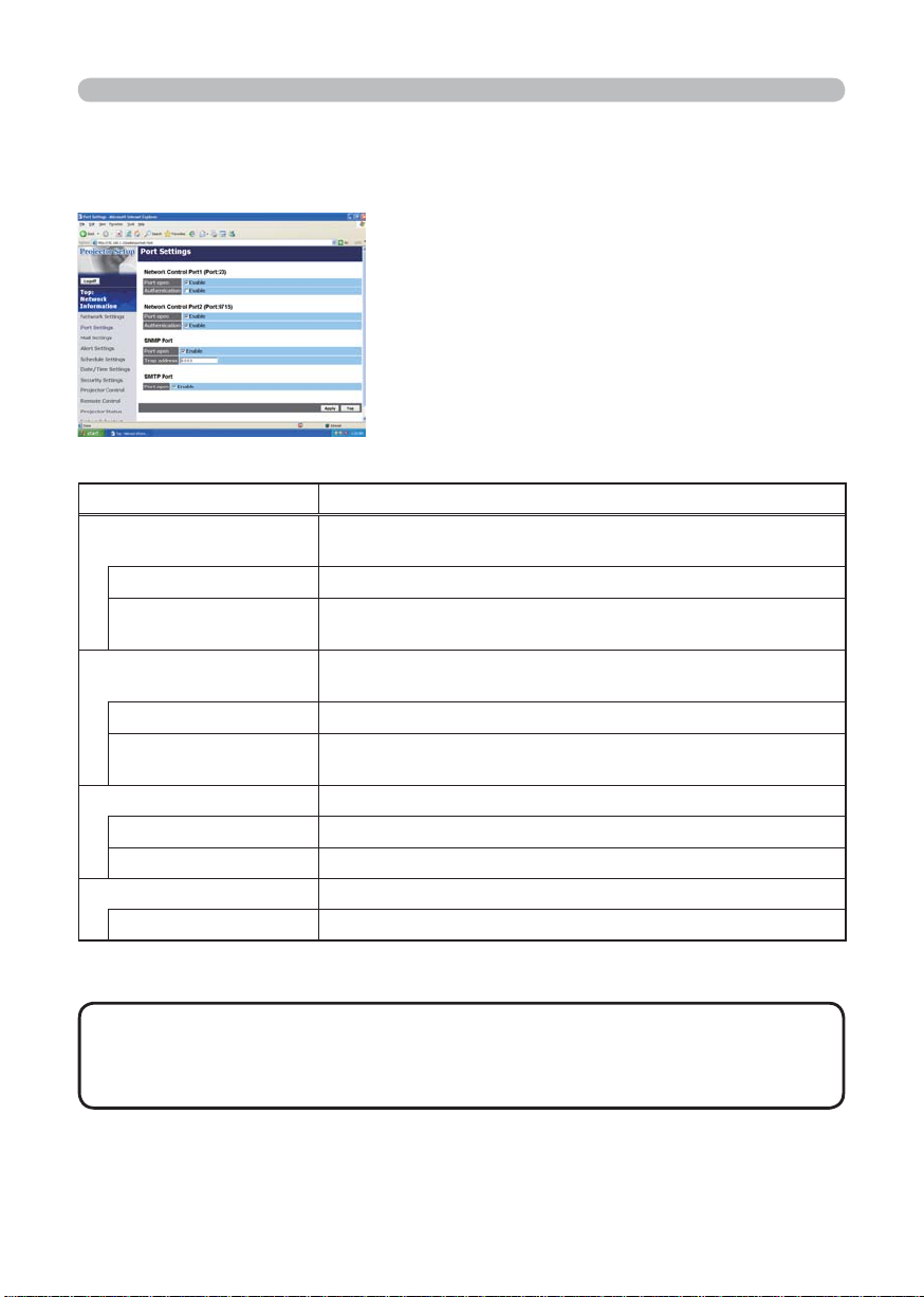
2.5.3 Port Settings
Displays and confi gures communication port settings.
Item Description
Network Control Port1
(Port:23)
Port open Click the [Enable] check box to use port 23.
Authentication
Network Control Port2
(Port:9715)
Port open Click the [Enable] check box to use port 9715.
Authentication
SNMP Port Confi gures the SNMP port.
Port open Click the [Enable] check box to use SNMP.
Trap address Confi gures the destination of the SNMP Trap in IP format.
SMTP Port Confi gures the SMTP port.
Port open Click the [Enable] check box to use the e-mail function.
Confi gures command control port 1 (Port:23).
Click the [Enable] check box when authentication is required
for this port.
Confi gures command control port 2 (Port:9715).
Click the [Enable] check box when authentication is required
for this port.
Click the [Apply] button to save the settings.
NOTE
• The new confi guration settings are activated after restarting the
network connection. The network connection must be restarted when the
confi guration settings are changed. The network connection can be restarted
using [Network Restart] on the main menu.
25
2. Equipment connection and network setting
2.5 Confi guring and controlling the projector via a web browser (Continued)
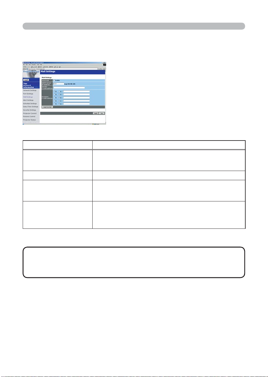
2.5.4 Mail Settings
Displays and confi gures e-mail addressing settings.
Item Description
Send Mail
SMTP Server IP Address Confi gures the address of the mail server in IP format.
Sender E-mail address
Recipient E-mail address
Click the [Enable] check box to use the e-mail function.
Confi gure the conditions for sending email under [Alert
Settings].
Confi gures the sender e-mail address.
The length of the sender e-mail address can be up to 255
alphanumeric characters.
Confi gures the e-mail address of up to fi ve recipients. You
can also specify [TO] or [CC] for each address. The length of
the recipient e-mail address can be up to 255 alphanumeric
characters.
Click the [Apply] button to save the settings.
NOTE
• You can confi rm whether the mail settings work correctly using the
[Send Test Mail] button.
• If you connect the projector to an existing network, consult a network
administrator before setting server addresses.
26

2. Equipment connection and network setting
2.5 Confi guring and controlling the projector via a web browser (Continued)
2.5.5 Alert Settings
Displays and confi gures failure & warning alerts.
Item Description
Cover Error Confi gures Cover Error alert settings.
SNMP Trap
Send Mail
Mail Subject
Mail Text
Fan Error Confi gures Fan Error alert settings.
SNMP Trap
Send Mail
Mail Subject
Mail Text
Click the [Enable] check box to enable SNMP Trap alerts for
this item.
Click the [Enable] check box to enable e-mail alerts for this
item.
Confi gures the subject line of the e-mail to be sent.
The length of the subject line can be up to 255 alphanumeric
characters.
Confi gures the text of the e-mail to be sent.
The length of the text can be up to 1024 alphanumeric
characters.
Click the [Enable] check box to enable SNMP Trap alerts for
this item.
Click the [Enable] check box to enable e-mail alerts for this
item.
Confi gures the subject line of the e-mail to be sent.
The length of the subject line can be up to 255 alphanumeric
characters.
Confi gures the text of the e- mail to be sent.
The length of the text can be up to 1024 alphanumeric
characters.
27

2. Equipment connection and network setting
2.5 Confi guring and controlling the projector via a web browser (Continued)
2.5.5 Alert Settings (Continued)
Item Description
Lamp Error Confi gures Lamp Error alert settings.
SNMP Trap
Send Mail
Mail Subject
Mail Text
Temp Error Confi gures Temp Error alert settings.
SNMP Trap
Send Mail
Mail Subject
Mail Text
Air Flow Error Confi gures Air Flow Error alert settings.
SNMP Trap
Send Mail
Mail Subject
Mail Text
Click the [Enable] check box to enable SNMP Trap alerts for
this item.
Click the [Enable] check box to enable e-mail alerts for this
item.
Confi gures the subject line of the e-mail to be sent.
The length of the subject line can be up to 255 alphanumeric
characters.
Confi gures the text of the e-mail to be sent.
The length of the text can be up to 1024 alphanumeric
characters.
Click the [Enable] check box to enable SNMP Trap alerts for
this item.
Click the [Enable] check box to enable e-mail alerts for this
item.
Confi gures the subject line of the e-mail to be sent.
The length of the subject line can be up to 255 alphanumeric
characters.
Confi gures the text of the e-mail to be sent.
The length of the text can be up to 1024 alphanumeric
characters.
28

2. Equipment connection and network setting
2.5 Confi guring and controlling the projector via a web browser (Continued)
2.5.5 Alert Settings (Continued)
Item Description
Lamp Time Error Confi gures Lamp Time Error alert settings.
SNMP Trap
Send Mail
Mail Subject
Mail Text
Cool Error Confi gures Cool Error alert settings.
SNMP Trap
Send Mail
Mail Subject
Mail Text
Filter Error Confi gures Filter Error alert settings.
SNMP Trap
Send Mail
Mail Subject
Mail Text
Click the [Enable] check box to enable SNMP Trap alerts for
this item.
Click the [Enable] check box to enable e-mail alerts for this
item.
Confi gures the subject line of the e-mail to be sent.
The length of the subject line can be up to 255 alphanumeric
characters.
Confi gures the text of the e-mail to be sent.
The length of the text can be up to 1024 alphanumeric
characters.
29

2. Equipment connection and network setting
2.5 Confi guring and controlling the projector via a web browser (Continued)
2.5.5 Alert Settings (Continued)
Item Description
Other Error Confi gures Other Error alert settings.
SNMP Trap
Send Mail
Mail Subject
Mail Text
Schedule Execution Error
SNMP Trap
Send Mail
Mail Subject
Mail Text
Lamp Time Alarm Confi gures Lamp Time Alarm alert settings.
Alarm Time Confi gures the lamp time to alert.
SNMP Trap
Send Mail
Mail Subject
Mail Text
Click the [Enable] check box to enable SNMP Trap alerts for
this item.
Click the [Enable] check box to enable e-mail alerts for this
item.
Confi gures the subject line of the e-mail to be sent.
The length of the subject line can be up to 255 alphanumeric
characters.
Confi gures the text of the e-mail to be sent.
The length of the text can be up to 1024 alphanumeric
characters.
Confi gures Schedule Execution Error alert settings.
Click the [Enable] check box to enable SNMP Trap alerts for
this item.
Click the [Enable] check box to enable e-mail alerts for this
item.
Confi gures the subject line of the e-mail to be sent.
The length of the subject line can be up to 255 alphanumeric
characters.
Confi gures the text of the e-mail to be sent.
The length of the text can be up to 1024 alphanumeric
characters.
30

2. Equipment connection and network setting
2.5 Confi guring and controlling the projector via a web browser (Continued)
2.5.5 Alert Settings (Continued)
Item Description
Filter Time Alarm Confi gures Filter Time Alarm alert settings.
Alarm Time Confi gures the fi lter time to alert.
SNMP Trap
Send Mail
Mail Subject
Mail Text
Transition Detector Alarm
SNMP Trap
Send Mail
Mail Subject
Mail Text
“CHANGE THE LAMP” is
displayed
SNMP Trap
Send Mail
Mail Subject
Mail Text
Cold Start Confi gures Cold Start alert settings.
SNMP Trap
Authentication Failure Confi gures Authentication Failure alert settings.
SNMP Trap
Click the [Apply] button to save the settings.
Click the [Enable] check box to enable SNMP Trap alerts for
this item.
Click the [Enable] check box to enable e-mail alerts for this
item.
Confi gures the subject line of the e-mail to be sent.
The length of the subject line can be up to 255 alphanumeric
characters.
Confi gures the text of the e-mail to be sent.
The length of the text can be up to 1024 alphanumeric characters.
Confi gures Transition Detector Alarm alert settings.
Click the [Enable] check box to enable SNMP Trap alerts for
this item.
Click the [Enable] check box to enable e-mail alerts for this
item.
Confi gures the subject line of the e-mail to be sent.
The length of the subject line can be up to 255 alphanumeric
characters.
Confi gures the text of the e-mail to be sent.
The length of the text can be up to 1024 alphanumeric characters.
Confi gures alert settings for when “CHANGE THE LAMP” is
displayed.
Click the [Enable] check box to enable SNMP Trap alerts for
this item.
Click the [Enable] check box to enable e-mail alerts for this item.
Confi gures the subject line of the e-mail to be sent.
The length of the subject line can be up to 255 alphanumeric
characters.
Confi gures the text of the e-mail to be sent.
The length of the text can be up to 1024 alphanumeric characters.
Click the [Enable] check box to enable SNMP Trap alerts for
this item.
Click the [Enable] check box to enable SNMP Trap alerts for
this item.
31

2. Equipment connection and network setting
2.5 Confi guring and controlling the projector via a web browser (Continued)
2.5.6 Schedule Settings
Displays and confi gures schedule settings.
Item Description
Daily Confi gures the daily schedule.
Schedule Click the [Enable] check box to enable daily scheduling.
Schedule List Displays the current daily schedule.
Sunday Confi gures the Sunday schedule.
Schedule Click the [Enable] check box to enable Sunday scheduling.
Schedule List Displays the current Sunday schedule.
Monday Confi gures the Monday schedule.
Schedule Click the [Enable] check box to enable Monday scheduling.
Schedule List Displays the current Monday schedule.
Tuesday Confi gures the Tuesday schedule.
Schedule Click the [Enable] check box to enable Tuesday scheduling.
Schedule List Displays the current Tuesday schedule.
Wednesday Confi gures the Wednesday schedule.
Schedule
Schedule List Displays the current Wednesday schedule.
Thursday Confi gures the Thursday schedule.
Schedule Click the [Enable] check box to enable Thursday scheduling.
Schedule List Displays the current Thursday schedule.
Friday Confi gures the Friday schedule.
Schedule Click the [Enable] check box to enable Friday scheduling.
Schedule List Displays the current Friday schedule.
Saturday Confi gures the Saturday schedule.
Schedule Click the [Enable] check box to enable Saturday scheduling.
Schedule List Displays the current Saturday schedule.
32
Click the [Enable] check box to enable Wednesday scheduling.

2. Equipment connection and network setting
2.5 Confi guring and controlling the projector via a web browser (Continued)
2.5.6 Schedule Setting (Continued)
Item Description
Specifi c date No1 Confi gures the specifi c date (No.1) schedule.
Schedule
Month/Day Confi gures the Month and date.
Schedule List Displays the current specifi c date (No.1) schedule.
Specifi c date No.2 Confi gures the specifi c date (No.2) schedule.
Schedule
Month/Day Confi gures the Month and date.
Schedule List Displays the current specifi c date (No.2) schedule.
Specifi c date No.3 Confi gures the specifi c date (No.3) schedule.
Schedule
Month/Day Confi gures the Month and date.
Schedule List Displays the current specifi c date (No.3) schedule.
Specifi c date No.4 Confi gures the specifi c date (No.4) schedule.
Schedule
Month/Day Confi gures the Month and date.
Schedule List Displays the current specifi c date (No.4) schedule.
Specifi c date No.5 Confi gures the specifi c date (No.5) schedule.
Schedule
Month/Day Set the Month and date.
Schedule List Displays the current specifi c date (No.5) schedule.
Click the [Enable] check box to enable specifi c date (No.1)
scheduling.
Click the [Enable] check box to enable specifi c date (No.2)
scheduling.
Click the [Enable] check box to enable specifi c date (No.3)
scheduling.
Click the [Enable] check box to enable specifi c date (No.4)
scheduling.
Click the [Enable] check box to enable specifi c date (No.5)
scheduling.
Click the [Apply] button to save the settings.
33

2. Equipment connection and network setting
2.5 Confi guring and controlling the projector via a web browser (Continued)
2.5.6 Schedule Setting (Continued)
To add additional functions and events click the [Add] button and set the following
items.
Item Description
Time Confi gures the time to execute commands.
Command Confi gures the commands to be executed.
Power Parameter Confi gures the parameters for power control.
Input Source
Parameter
Display Image
Parameter
Confi gures the parameters for input switching.
Confi gures the parameters for display of transfer image data.
Click the [Register] button to add new commands to the Schedule List.
Click the [Delete] button to delete commands from the Schedule List.
2.5.7 Date/Time Settings
Displays and confi gures the date and time settings.
Item Description
Current Date Confi gures the current date in Year/Month/Day format.
Current Time Confi gures the current time in Hour:Minute:Second format.
34

2. Equipment connection and network setting
2.5 Confi guring and controlling the projector via a web browser (Continued)
2.5.7 Date/Time Settings (Continued)
Item Description
Daylight Savings Time
Start Confi gures the date and time daylight savings time begins.
Month Confi gures the month daylight savings time begins (1~12).
Week
Day
Hour Confi gures the hour daylight savings time begins (0 ~ 23).
Minute Confi gures the minute daylight savings time begins (0 ~ 59).
End Confi gures the date and time daylight savings time ends.
Month Confi gures the month daylight savings time ends (1 ~ 12).
Week
Day
Hour Confi gures the hour daylight savings time ends (0 ~ 23).
Minute Confi gures the minute daylight savings time ends (0 ~ 59).
Time difference
SNTP
SNTP Server IP Address
Cycle
Click the [ON] check box to enable daylight savings time and
set the following items.
Confi gures the week of the month daylight savings time
begins (First, 2, 3, 4, Last).
Confi gures the day of the week daylight savings time begins
(Sun, Mon, Tue, Wed, Thu, Fri, Sat).
Confi gures the week of the month daylight savings time ends
(First, 2, 3, 4, Last).
Confi gures the day of the week daylight savings time ends
(Sun, Mon, Tue, Wed, Thu, Fri, Sat).
Confi gures the time difference (hours:minutes).
Set the same time difference as the one set on your PC. If
unsure, consult your network administrator.
Click the [ON] check box to retrieve Date and Time
information from the SNTP server and set the following items.
Confi gures the SNTP server address in IP format.
Confi gures the interval at which to retrieve Date and Time
information from the SNTP server. (hours:minutes).
Click the [Apply] button to save the settings.
•
NOTE
The new confi guration settings are activated after restarting the network connection.
The network connection must be restarted when the confi guration settings are changed, The
network connection can be restarted using [Network Restart] on the main menu.
•
If you connect the projector to an existing network, consult a network administrator before setting server addresses.
• To enable the SNTP function, the time difference must be set.
• The projector will retrieve DATE and TIME information from the timeserver
and override time settings when SNTP is enabled.
•
The Internal Clock’s time may not remain accurate. Using SNTP is recommended to maintain accurate time.
35

2. Equipment connection and network setting
2.5 Confi guring and controlling the projector via a web browser (Continued)
2.5.8 Security Settings
Displays and confi gures passwords and other security settings.
Item Description
Administrator authority Confi gures the Administrator ID and Password.
Administrator ID
Administrator
Password
Re-enter Administrator
Password
User authority Confi gures the User ID and Password.
User ID
User Password
Re-enter User
Password
Confi gures the Administrator ID.
The length of the text can be up to 32 alphanumeric
characters.
Confi gures the Administrator Password.
The length of the text can be up to 255 alphanumeric
characters.
Re-enter the above password for verifi cation.
Confi gures the User ID.
The length of the text can be up to 32 alphanumeric
characters.
Confi gures the User Password.
The length of the text can be up to 255 alphanumeric
characters.
Used to re-enter the above password for verifi cation.
36

2. Equipment connection and network setting
2.5 Confi guring and controlling the projector via a web browser (Continued)
2.5.8 Security Settings (Continued)
Item Description
Network Control
Authentication
Password
Re-enter Authentication
Password
SNMP Confi gures the community name if SNMP is used.
Community Name
FTP Confi gures the FTP user and password.
USER
Password
Re-enter Password Use to re-enter the above password for verifi cation.
Confi gures the Authentication Password for the command
control.
Confi gures the Authentication Password.
The length of the text can be up to 16 alphanumeric
characters.
Used to re-enter the above password for verifi cation.
Confi gures the community name.
The length of the text can be up to 64 alphanumeric
characters.
Confi gures the user name. The length of the text can be up
to 32 alphanumeric characters.
Confi gures the password. The length of the text can be up to
32 alphanumeric characters.
Click the [Apply] button to save the settings.
NOTE
• The new confi guration settings are activated after restarting the
network connection. The network connection must be restarted when the
confi guration settings are changed. The network connection can be restarted
using [Network Restart] on the main menu.
37

2. Equipment connection and network setting
2.5 Confi guring and controlling the projector via a web browser (Continued)
2.5.9 Projector Control
The items shown in the table below can be
performed using the [Projector Control] menu.
Select an item using the up and down arrow keys
on the PC.
Most of the items have a submenu.
Refer to the table below for details.
Controls the projector.
Item Description
Main
Power Turns the power On/Off.
Input Source Selects the input source.
Picture Mode Selects the Picture Mode setting.
Blank On/Off Turns Blank On/Off.
Mute Turns Mute On/Off.
Freeze Selects the Freeze setting.
Magnify Controls the Magnify setting.
Picture
Brightness Adjusts the Brightness setting.
Contrast Adjusts the Contrast setting.
Gamma Selects the Gamma setting.
Color Temp Selects the Color Temp setting.
Color Adjusts the Color setting.
Tint Adjusts the Tint setting.
Sharpness Adjusts the Sharpness setting.
Active Iris Selects the Active Iris setting.
MyMemory Recall Recalls the MyMemory data.
MyMemory Save Saves the MyMemory data.
38

2. Equipment connection and network setting
2.5 Confi guring and controlling the projector via a web browser (Continued)
2.5.9 Projector Control (Continued)
Item Description
Image
Aspect Selects the Aspect setting.
Over Scan Selects the Over Scan setting.
V Position Adjusts the V Position.
H Position Adjusts the H Position.
H Phase Adjusts the H Phase.
H Size Adjusts the H Size.
Auto Adjust Performs Auto Adjustment.
Input
Progressive Selects the progressive setting.
Video NR Selects the Video NR setting.
Color Space Selects the Color Space.
Component Selects the Component terminal setting.
C-Video Format Selects the Video Format setting.
S-Video Format Selects the S-Video Format setting.
Frame Lock Enables/Disables Frame Lock.
RGB in-1 Selects the RGB1 input signal type.
RGB in-2 Selects the RGB2 input signal type.
Setup
Auto Keystone Execute
Keystone Adjusts the Keystone setting.
Whisper Selects the Fan speed. (Normal or Whisper)
Mirror Selects the Mirror status.
Volume Adjusts the Volume setting.
Audio-RGB1 Assigns the Audio-RGB1 input terminal.
Audio-RGB2 Assigns the Audio-RGB2 input terminal.
Audio-Video Assigns the Audio-Video input terminal.
Audio-S-Video Assigns the Audio-S-Video input terminal.
Audio-Component Assigns the Audio-Component input terminal.
Audio-MIU Assigns the Audio-MIU input terminal.
Performs the Automatic keystone distortion correction.
39

2. Equipment connection and network setting
2.5 Confi guring and controlling the projector via a web browser (Continued)
2.5.9 Projector Control (Continued)
Item Description
Screen
Language Selects the Language for the OSD.
Menu Position V Adjusts the vertical Menu Position.
Menu Position H Adjusts the horizontal Menu Position.
Blank Selects the Blank mode.
Startup Selects the Startup screen mode.
MyScreen Lock Turns MyScreen Lock On/Off.
Message Turns the Message function On/Off.
Option
Auto Search Turns the Automatic signal search function On/Off.
Auto Keystone
Auto on Turns the Auto on function On/Off.
Auto off
My Button-1
My Button-2
Auto Adjust Enables/Disables Auto Adjustment.
Remote Freq. Normal Enable/Disable
Remote Freq. High Enable/Disable
Turns the Automatic keystone distortion correction function On/Off.
Confi gures the timer to shut off the projector when no signal
is detected.
Assigns the functions for the MY BUTTON1 buttons on the
included remote control.
Assigns the functions for the MY BUTTON2 buttons on the
included remote control.
40

2. Equipment connection and network setting
2.5 Confi guring and controlling the projector via a web browser (Continued)
2.5.10 Projector Status
Displays and confi gures the current projector status.
Item Description
Error Status Displays the current error status
Lamp Time Displays the usage time for the current lamp.
Filter Time Displays the usage time for the current fi lter.
Power Status Displays the current power status.
Input Status Displays the current input signal source.
Blank On/Off Displays the current Blank On/Off status.
Mute Displays the current Mute On/Off status.
Freeze Displays the current Freeze On/Off status.
2.5.11 Network Restart
Restarts the projector’s network connection.
Item Description
Restart
NOTE
• Restarting requires you to re-log on in order to further control or
Restarts the projector’s network connection in order to
activate new confi guration settings.
confi gure the projector via a web browser.
2.5.12 Logoff
When logoff is clicked, the logon screen is displayed (
21 : Fig. 2.5.a).
41

2. Equipment connection and network setting
2.6 Utilize Web Remote Control
You can use your Web browser to remote control the projector once the projector
is properly confi gured and connected to your PC via the wireless LAN card or via
wired LAN.
NOTE
• Do not attempt to control the projector with the projector's remote
control and via your Web browser at the same time. Attempt to do so may
causes a projector operational error.
Open browser when it is possible to communicate with projector. Corresponding
browser is Internet Explorer 5.5 or later.
Specify http://(projector IP address)/ to start.
For example, http://192.168.1.10/
(Input this URL when IP address is not changed.)
After start up, enter your ID and password, and click [Logon]. Following window
appears as shown in fi g. 2.6.a.
42
Fig. 2.6.a Utility selection window for Web Remote Control

2. Equipment connection and network setting
2.6 Utilize Web Remote Control (Continued)
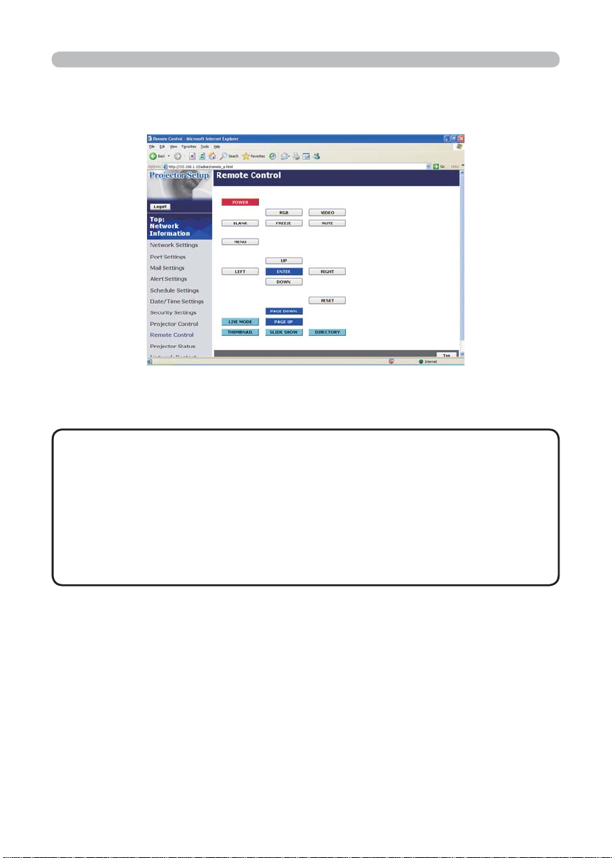
Click “Remote Control” in this window to display Web Remote Control as shown in
fi g.2.6.b.
The same operation as the
bundled remote control will done.
UP/LEFT/RIGHT/DOWN
corresponds to ▲/◄/►/▼
respectively.
Each mode will be activated by
clicking these buttons.
• LIVE MODE
• THUMBNAIL
• SLIDE SHOW
• DIRECTORY
Fig. 2.6.b Web Remote Control
NOTE
• Web Remote Control does not support repeat function when it is kept
clicking.
• Since automatic repeat function is not available, click the button necessary
times to reach your demand.
• If you click the button continuously, some command will not be transferred.
Wait for a while, and Click again.
•
When the power button is pushed, a message comes up to confi rm the operation.
If you wish to turn it off, push OK, otherwise push CANCEL.
•
PAGE DOWN and PAGE UP buttons on web remote control can not be used as
mouse emulation function of the projector.
43

3. How to use Projector software – Basics -
3. How to use Projector software – Basics -
3. How to use Projector software – Basics -
3.1 How to use “MIU Live Viewer”
This section explains how to use the “MIU Live Viewer”.
3.1.1. Install “MIU Live Viewer”
In order to use the projector with a PC for Live Mode, you will fi rst need to install
the accompanying software on all the PCs you will be using.
Minimum PC Hardware and Software Requirements
• OS: Windows 2000 Professional Service Pack4,
Windows XP Home Edition/Professional
• Graphic Interface: DirectX 6.1a or higher; Video RAM 4MB or higher
(8MB recommended)
• CPU: Pentium III (600MHz or higher recommended)
• Display:
simultaneous colors or higher
VGA 640x480 or higher (XGA 1024x768 recommended) 65,536
NOTE
• In some cases, Screen will not be displayed correctly like no displays larger
than XGA portion.
• Images might not been transmitted, caused by OS version or the driver
software for Network Adaptor.
It is highly recommended that OS and the driver should be updated to the latest.
• Memory: 64MB or higher (128MB or higher if using Windows XP)
•
Available Hard Disk Space
• Web browser: Internet Explorer® (5.5 or higher)
• CD-ROM drive
• PC with PC card slot (PCMCIA Type-II) interface and IEEE802.11g wireless
LAN PC card or PC with USB Interface and IEEE802.11g wireless LAN USB
adaptor.
NOTE
• Depending on the type of wireless LAN card and PC you are using, the
projector may not be able to communicate properly with your PC, even if the
PC you are using is equipped with built-in wireless LAN functionality.
Should communication problems occur, please procure a Wi-Fi certifi ed
wireless LAN card.
• Set your PC’s resolution to XGA or less.
: 10MB or higher
• Not required for PCs with built-in 802.11g wireless LAN.
44

3. How to use Projector software – Basics -
3.1 How to use “MIU Live Viewer” (Continued)
3.1.2. Software Installation Procedure
1) Turn on the PC.
2) Shut down all applications.
3) Insert the X62w Operator's Guide CD-ROM
into the PC's CD-ROM drive.
Also visit www.3m.com/meetings for "MIU Live
Viewer" software update.
4) After a moment, the Welcome to MIU Utilities
Setup dialog will appear as shown on the right.
Press Next.
NOTE
If the Welcome to MIU Utilities Setup dialog doesn't appear, proceed as
follows:
(1) Click on the Start button on the toolbar and select Run.
(2) Enter E:\software\setup.exe and then press OK.
If your CD-ROM drive is not drive E on your PC, you will need to
replace E with the correct drive letter assigned to your CD-ROM drive.
If software has been already installed, Uninstallation will be done. Click the cancel
button, then uninstallation will be canceled. If you uninstalled the software by misoperation, please re-install the software from fi rst procedure.
5) The License Agreement dialog appears. If you
accept it, press the “Yes”.
6) The Choose Destination Location dialog
appears. Press Next.
NOTE
• The C:\Program Files\MIU_Utility folder will be created and the
program will be installed into that folder.
•
If you wish to install to a different folder, click Browse and select another folder.
7) Confi rm the program folder name.
If MIU_Utility is okay, press Next to continue.
If not, enter the desired folder name and then
press Next.
45

3. How to use Projector software – Basics -
3.1 How to use “MIU Live Viewer” (Continued)
8) The Hardware Installation dialog appears.
Press Continue Anyway.
9) After a moment, installation will complete and
the Setup Complete dialog will appear as
shown on the right. Click Finish.
This completes the software installation. Then
your PC automatically restarts.
(1) To confi rm that the software as been
properly installed, press the Start button on
the toolbar, select All Programs and then
select the MIU Utility folder.
(2) MIU Live Viewer will appear in that folder if
the installation was successful.
3.1.3 Explanation of “MIU Live Viewer”
Double click “LiveViewer.exe” to start up. Fig. 3.1.3.a appears on your screen.
46
q
e
s
r
a
w
o
Fig. 3.1.3.a “MIU Live Viewer” Window
t
y
u
i

3. How to use Projector software – Basics -
3.1 How to use “MIU MIU Live Viewer” (Continued)
[“MIU Live Viewer” window: Fig. 3.1.3.a]
1) “File” button
Display fi le menu.
2) “Help” button
Display “MIU Live Viewer” information.
3) Stop button
Disconnect projector connection.
4) Capture start button
Start real time display.
NOTE
• Pictures are not displayed correctly when the start/stop buttons are
clicked repeatedly.
5) Minimize button
Close “MIU Live Viewer” window and display “MIU Live Viewer” as icon on the
task tray.
6) “Option” button
Display Option window.
7) “Refresh” button
Refresh the current PC network setting.
8) “Exit” button
Terminate “MIU Live Viewer”.
9) “Find” button
Search connectable projectors.
10) “One-Click” button
Connect projector and PC without network setting of the PC.
11) “Enable Device”
Display network-connectable projector list.
NOTE
• When Multi PC mode is not selected, if there is no other PC
connected, the last image will be held on screen until getting out of Live Mode
or turning the projector off.
Thanks to the feature, the PC can be used to prepare the next presentation fi le
or others without showing it on screen if the communication to the projector is
turned off.
47

3. How to use Projector software – Basics -
3.1 How to use “MIU Live Viewer” (Continued)
[“Options” window]
[“General” tab, Fig. 3.1.3.b]
Fig.3.1.3.b “Options”, “General” tab
1) CPU Share
Set up any capturing performance on the PC screen by using control bar
Low (At the far left): Set this position when many CPU resources are required
by applications other than “MIU Live Viewer”. This setting is not
good for displaying frequently changed patterns due to decrease in
screen refresh rate by “MIU Live Viewer” performance degrading.
High (At the far right): Set this position when “MIU Live Viewer” requires many
CPU resources. Screen refresh rate increases when “MIU Live
Viewer” is used, but decreases the speed of other application
speed.
2) MultiPC Mode
Select connected PC quantity from 1PC to 4PCs.
3) Cursor Emulation
Enabling this function “ON”, display cursor (pointer) prepared by this projector
when cursor is not displayed on output screen. Take out check mark to make it
“OFF” when PC and projector both cursors are displayed.
48

3. How to use Projector software – Basics -
3.1 How to use “MIU Live Viewer” (Continued)
[JPEG tab]
Fig. 3.1.3.c “Options”, “JPEG” tab
1) JPEG Quality
When “MIU Live Viewer” is used, it captures PC screen image. Then that is
compressed as JPEG and sent to projector. By control bar in this tab, you can
set compression rate.
Low (At the far left, Low picture quality): Make JEPG compression rate high.
Screen refresh interval becomes shorter due to low volume
transferred data, but picture quality decreases.
High (At the far right, High picture quality): Make JEPG compression rate
low. Screen refresh interval becomes longer due to high volume
transferred data, but picture quality increases.
[Icon in task tray]
To display “MIU Live Viewer” icon in task tray, click “Minimize” button in “MIU Live
Viewer” window. The icon with yellow thunder mark shows that communication is
connected, and it with red cross mark shows that it is disconnected. (Fig. 3.1.3.d
shows while communication is disconnected.)
Fig. 3.1.3.d Icon in task tray
Double click “MIU Live Viewer” icon in task tray to display “MIU Live Viewer”
window.
49

3. How to use Projector software – Basics -
3.1.4 Utilize “MIU Live Viewer” – Basic -
This section explains basic of how to use “MIU Live Viewer” functions.
• Before start up the MIU Live Viewer, you have to set the projector into LIVE
MODE by either of following way.
1) from Web Remote Control
(1) Select LIVE MODE
2) from OSD Menu
(1) Set the port into MIU menu by remote control or Keypad.
(2) Open the OSD Menu by pressing ▲/◄/►/▼ Keypad button on the projector
or Menu button on remote control.
(3) Select the LIVE MODE in MIU Menu, and press the ► button on Keypad on
the projector or Enter button on remote control.
/'07=4)$?
2+%674'
+/#)'
+0276
5'672
5%4''0
126+10
/+7
'#5;/'07
.+8'/1&'
2%.'5524'5'06#6+10
5'672
G5*16
+0(14/#6+10
5'48+%'
5'.'%6
• After setting to the projector into LIVE MODE.
1) Start “MIU Live Viewer”. If “MIU Live Viewer” installation is not completed,
install it referring to 3.1.1 Install “MIU Live Viewer”.
50
Fig. 3.1.4.a Screen after “MIU Live Viewer” starting up

3. How to use Projector software – Basics -
3.1 How to use “MIU Live Viewer” (Continued)
2) Start Web Remote Control (refer to 2.6 Utilize Web Remote Control), and click
“LIVE MODE” button on Web Remote Control to change projector mode to
“MIU Live Viewer”. After changing, screen of the output monitor connected with
projector turn all blue.
3) Perform following operations on “MIU Live Viewer”
(1) Click “Find” button to search communication available projector. If any
projector is not found at “Enable Device” tab, try search again after referring
section 2.2.
Display communication possible
projector like this if available as a
result of search.
Fig. 3.1.4.b. Projector research result display (1)
(2) When communication available projector is found at 1), click the found
projector to select
Click the projector line to connect.
IP address appears in the upper
column.
Fig. 3.1.4.c Projector research result display (2)
51

3. How to use Projector software – Basics -
3.1 How to use “MIU Live Viewer” (Continued)
(3) Click Capture start button.
Fig. 3.1.4.d Start capturing
Based on the above operation, if captured picture of PC screen is displayed real
time on monitor connected with projector, it is succeeded. Much easier to connect
if you utilize “One-Click-Communication” function. (Refer to section 2.2.)
This is basic usage. Refer to section 4.1 for further explanation of advanced MIU
Live Viewer usage.
3.2 Utilize “PC-LESS Presentation” – Basic -
Explain basics of how to utilize “PC-LESS Presentation”.
1) Save JPEG picture fi les into root directory in SD card or USB Memory. Insert
SD card into SD slot on projector or insert USB memory into AUX I/O slot on
projector (
2) Connecting as network refer to section 3 and start the Web Remote Control.
3) Click “THUMBNAIL” button on the Web Remote Control to change projector
mode to “PC-LESS Presentation”. Then thumbnail appears.
To remove the SD card or USB memory,
4)
Be sure to perform the REMOVE procedure using the SERVICE item in the MIU
menu (
procedure, please re-perform the procedure after waiting for a while.
5)
When you remove the SD wireless network card, be sure to turn the projector off.
6) Remove the SD card or USB Memory. For removing the SD card, remove the
SD card slot cover before, and put the cover back after.
52
Inserting an SD card and USB memory of the Operator's Guide).
MIU Menu of the
Operator's Guide
). When an error dialog appears in the

3. How to use Projector software – Basics -
3.2 Utilize “PC-LESS Presentation” –Basic - (Continued)
If thumbnail appears by above operation, it is succeeded. (Fig.3.2.a) This is basic
usage. There are varieties of usage for “PC-LESS Presentation”. Refer to section
4.2 for further detailed explanation.
6*7/$0#+.=5&?
㪈㪉㪊
+OCIG
+OCIG
㪌㪍㪋
+OCIG
+OCIG
㪏㪐㪎
+OCIG
+OCIG
㪈㪈 㪈㪉㪈㪇
+OCIG
+OCIG
;'5
'06'4
+OCIG
+OCIG
+OCIG
+OCIG
2%.'55
24'5'06#6+10
/'07
5.+&'5*19
56#46
5612
+06'48#.5
/1&'
10'6+/'
2.#;
Fig. 3.2.a Thumbnail display
You can also activate “PC-LESS Presentation” from the OSD Menu.
1) Open the OSD Menu from the Menu button on the remote control or ▲/◄/►/▼
button on Keypad.
2) Select “PC-LESS Presentation” on the MIU Menu. And press the Enter button
on the remote control or ► button on Keypad. Then PC-LESS PRESENTATION
Menu appears.
/'07=4)$?
2+%674'
+/#)'
+0276
5'672
5%4''0
126+10
/+7
.+8'/1&'
2%.'5524'5'06#6+10
5'672
G5*16
+0(14/#6+10
5'48+%'
5'.'%6
2%.'5524'5'06#6+10
6*7/$0#+.
5.+&'5*19
&+4'%64;
&+52.#;5+<'
-';%10(+)
'#5;/'07
3) Select THUMBNAIL on PC-LESS PRESENTATION Menu. And press the Enter
button on remote control or ► button on Keypad. Then thumbnail appears.
Caution
• Do not pull out memory card while fi le is accessed.
• SDHC(4GB etc) SD memory is not supported. UP to 2GB.
• Some SD memories and/or USB memories will not work correctly.
• Security USB memory is not supported.
53

4. Utilize projector – Advanced -
4. Utilize projector – Advanced -
1
2
3
4
4. Utilize projector – Advanced -
4.1. Utilize “MIU Live Viewer” – Advanced -
This section explains how to connect multiple PCs.
4.1.1. Connect multiple PCs with one projector (Multiple PCs
connection)
A projector can be connected with up to 4 PCs to display multiple windows.
1
2
C
B
S
/
P
D
B
C
A
R
D
C
R
/
P
R
R
G
B
A
A
U
I
V
N
U
X
I
I/
1
D
D
AU
I
D
O
E
O
C
O
D
I
5
I
N
V
O
1
0
I
.
5
N
A
S
2
V
I
D
R
E
G
O
L
B
A
I
N
N
2
R
G
B
C
O
N
T
R
O
L
U
S
3
B
IN
C
O
A
U
T
AU
D
I
O
O
U
T
1
34
4
Fig. 4.1.1.a Multiple PCs connection outline
Followings are required for multiple PCs connection.
- From 2 to 4 PCs (“MIU Live Viewer” installation is required to all
PCs to connect.)
- Projector: 1 unit
- Straight LAN cable: Required qty*
- Ethernet hub
* It is required to make all wireless PCs enabling wireless communication when
doing multiple PCs connection as wireless LAN connection. SD-Link11g card for
projector is required. If it is communicated by Infrastructure mode, access point
is necessary. (
16)
2
54

4. Utilize projector – Advanced -
4.1. Utilize “MIU Live Viewer” – Advanced - (Continued)
[Connection]
1) Connect all PCs and projector using LAN cables and hub as shown in fi g.
4.1.1.a. Connect projector and output monitor with RGB cable.
2) Start up “MIU Live Viewer” in each PC. Check the IP address in PCs and
confi rm xxx of [192.168.1.xxx] in IP address is set different value in each PC.
3) Click “Find” button in “MIU Live Viewer” and search projector.
4) When projector is found, click “Option” button in “MIU Live Viewer”. Then open
“General” tub and select the number of PCs to connect as MultiPC Mode. After
selecting, click “Close” button.
5) Click Capturing Start button.
6) Repeat from 3) to 5) to all PCs.
* Display screen priority
In case of multiple PCs connection, priority is decided automatically comparing
when each PC is connected. In each mode, priority is as shown in fi g. 4.1.1.b.
(Smaller number is prioritized.)
2% 2%U 2%U 2%U
Detailed conditions and specifi cations for priority are as follows.
a) The priority is high the PC that connects later.
b) When Multi PC Mode (2 to 4 PCs) is changed to 1 PC, changed 1 PC has
highest priority.
c) Multi PC Mode can be changed settings freely even the PC is communicating.
d) When the lower number than connected PCs is selected, lower priority PC
screens are not displayed, but connections with projector are kept.
When more than 5 PCs are connected with projector, lower priority PC connection
is disconnected.
NOTE
changed, the PC will be given the top priority, so the mode (1 to 4PCs) set on
the PC will be effective on the projector.
• On Multi PC Mode, actual image resolution of each screen is 1/4 of the
original, then small letters or lines might be hard to be illegible.
It is recommended to use letters as large as possible. Or try manual H.Phase
adjustment which might improve image quality.
• When Multi PC is selected, if the screen resolution on one of PCs is
Fig. 4.1.1.b Priority in each mode
55

4. Utilize projector – Advanced -
4.2 Utilize “PC-LESS Presentation” – Advanced -
“PC-LESS Presentation” reads image data from memory cards inserted into SD or
USB slot and perform followings.
SD Memory and SD Wireless card can not be inserted at the same time.
- Thumbnail display (Section 4.2.1)
- Display in full screen (Section 4.2.2)
- Slide show (Section 4.2.3)
- Directory display (Section 4.2.4)
6*7/$0#+.=5&?
㪈㪉㪊
+OCIG
+OCIG
+OCIG
+OCIG
;'5
㪈㪈 㪈㪉㪈㪇
'06'4
+OCIG
㪌㪍㪋
+OCIG
㪏㪐㪎
+OCIG
+OCIG
+OCIG
+OCIG
+OCIG
+OCIG
2%.'55
24'5'06#6+10
/'07
5.+&'5*19
56#46
5612
+06'48#.5
/1&'
10'6+/'
2.#;
Fig. 4.2.a Thumbnail display Fig. 4.2.b Display in full screen
Fig. 4.2.c Slide show Fig. 4.2.d Directory display
56

4. Utilize projector – Advanced -
4.2 Utilize “PC-LESS Presentation” – Advanced - (Continued)
Following picture and movie fi les can be displayed.
• JPEG (.jpeg, .jpg) * Progressive is not corresponded.
• BMP (.bmp)
• PNG (.png)
• MPEG4 (.mp4) * Supported bit resolution rate is less than 1Mbps in Simple
Profi le.
Supported resolution is less than VGA.
Supported Audio format is only AAC.
4.2.1 Thumbnail display
Fig.4.2.1 shows thumbnail display. Click [THUMBNAIL] button in the Web Remote
Control to display menu on the screen in order to make thumbnail display.
You can also display thumbnail by remote control or keypad (
53).
Thumbnail Images
Focused image
6*7/$0#+.=5&?
㪈㪉㪊
+OCIG
+OCIG
+OCIG
+OCIG
;'5
㪈㪈 㪈㪉㪈㪇
'06'4
+OCIG
㪌㪍㪋
+OCIG
㪏㪐㪎
+OCIG
+OCIG
+OCIG
+OCIG
+OCIG
+OCIG
Fig. 4.2.1. Thumbnail display
2%.'55
24'5'06#6+10
/'07
5.+&'5*19
56#46
5612
+06'48#.5
/1&'
10'6+/'
2.#;
Thumbnail Menu
57

4. Utilize projector – Advanced -
4.2 Utilize “PC-LESS Presentation” – Advanced - (Continued)
Following operations can be accessible while thumbnail is displayed.
▲/◄/►/▼
Remote control/Keypad
PAGE UP
ENTER
INPUT
MENU
PAGE DOWN
Remote control
Remote control
Keypad
Remote control Displays PC-LESS PRESENTATION Menu.
Move cursor.
Switch pages.
Display selected image in full screen.
* These operations are not accessible while projector OSD menu is displayed.
NOTE
• Thumbnail display shows 12 pictures in 1 page as maximum.
• It is not possible to change the input port by INPUT button when THUMBNAIL,
SLIDE SHOW, or DIRECTORY is displayed.
• Displays the projector Menu before changing the input port .
• Select the right edge images and press the ► button, then thumbnail menu
will be selected.
• Some error Icons will be displayed in thumbnail.
This fi le seems to be broken or not supported format.
58
This fi le exists only in Playlist (
67), but does not exist anywhere.

4. Utilize projector – Advanced -
4.2 Utilize “PC-LESS Presentation” – Advanced - (Continued)
4.2.2 Display in full screen
Full screen display (fi g.4.2.2) shows a full display image on the PC. To make Full-
screen display, click [MENU] button in the Web Remote Control menu on the
screen. When select [PC-LESS Presentation], then [Thumbnail] from the menu,
click [ENTER] so that moves to be full-screen display.
Full-screen Display
Fig.4.2.2 Full-screen Display
While displaying in full screen, following operation can be accessible from the
Web Remote Control.
◄/►
or
▲/▼
(Selected on KEY
CONFIG. MENU
ENTER
INPUT
MENU
Remote control
Keypad
Remote control Displays PC-LESS PRESENTATION Menu.
60)
• Rotate image 90 degrees clockwise or otherwise. Once image
is rotated, it keeps the display image even though it is switched.
(Thumbnail or slide show display) To return the original, rotating
the image 360 degrees or erase play list in memory card. (Refer
to section 4.3)
• Moving the slide forward or backward.
Displaying thumbnail.
* These operations are not accessible while projector OSD menu is displayed.
NOTE
• It is not possible to change the input port by INPUT button of keypad
when displaying the THUMBNAIL, SLIDE SHOW, or DIRECTORY.
• Displays the projector Menu before changing the input port.
• Image might not be displayed properly at the beginning or end of MP4 fi le
playback.
59

4. Utilize projector – Advanced -
4.2 Utilize “PC-LESS Presentation” – Advanced - (Continued)
You can display the image fi le with your desired size.
1) Select the DISPLAY SIZE in PC-LESS PRESENTATION Menu.
2) Press the Enter button on the remote
control or ► button on the Keypad.
3) Then DISPLAY SIZE menu appears.
2%.'5524'5'06#6+10
6*7/$0#+.
5.+&'5*19
&+4'%64;
&+52.#;5+<'
-';%10(+)
&+52.#;5+<'
4'#.
014/#.
(7..
4) Select your desired DISPLAY SIZE.
• REAL : Displays the image at original size.
Displays the image at the center of screen if original size is smaller
than the screen size.
Displays only center of the image if original size is larger than the
screen size.
• NORMAL : Displays the image for the maximum size on the screen, and
keeps original aspect.
• FULL : Displays the image at the full size screen.
Original aspect will be changed to full size display.
The animation fi le is always played at VGA mode if resolution is larger than VGA.
The animation fi le is always played at the center of screen if resolution is smaller
than VGA.
You can select the KEY confi guration from 2 preset pattern assigned to ▲/▼/◄/►
keys on Tumbnail or Directory mode.
1) Select the KEY CONFIG. in PC-LESS PRESENTATION Menu.
2) Press ► button.
3) The KEY CONFIG. menu appears.
-';%10(+)
$#%- 0':6
$#%-
0':6
Pattern A
Pattern B
4) Select the KEY CONFIG. pattern.
• pattern A : ◄ : rotation to left ► : rotation to right
▲ : previous image ▼ : next image
• pattern B : ◄ : previous image ► : next image
▲ : rotation to right ▼ : rotation to left
60

4. Utilize projector – Advanced -
4.2 Utilize “PC-LESS Presentation” – Advanced - (Continued)
4.2.3. Slide show
Slide show (fi g.4.2.3) displays a full screen image and move to the next interval.
Click the “SLIDE SHOW” button in Web Remote Control, then Slide show will be
played. Display time can be set by the Playlist (refer to section 4.3) and menu.
Full-screen Display
Fig. 4.2.3 Slide show
Following operations are accessible while slide show is displayed.
ENTER
INPUT
MENU
Remote control
Keypad
Remote control Displays PC-LESS PRESENTATION Menu.
Display thumbnails.
* These operations are not accessible while projector OSD menu is displayed.
NOTE
• It is impossible to change the input port by INPUT button if
THUMBNAIL, SLIDE SHOW, or DIRECTORY is displayed.
• Displays the projector Menu before changing the input port .
• Images can be displayed when it is recorded in the Playlist.
•
Image can not be displayed in the thumbnail if it is not recorded in the Playlist.
(
67)
• The START #, STOP #, INTERVAL, and MODE are set by thumbnail menu
once, this setting has more priority than the Playlist.
• If you would like to release the priority, delete the slidemode.txt fi le from
directory.
• When SLIDE SHOW mode is set to ONE TIME, the last slide of the
presentation will be held on screen till either of ENTER key the remote or
INPUT key on the projector is pushed.
61

4. Utilize projector – Advanced -
4.2 Utilize “PC-LESS Presentation” – Advanced - (Continued)
You can also play the Slide show with the projector Menu.
Select “SLIDE SHOW” on PC-LESS PRESENTATION Menu. And press the Enter
button on the remote control or ► button on Keypad. Then Slide show will start.
2%.'5524'5'06#6+10
6*7/$0#+.
5.+&'5*19
&+4'%64;
&+52.#;5+<'
-';%10(+)
You can play the Slide show at your desired confi guration.
Confi gure the Slide Show items in THUMBNAIL.
1) START # : Set the beginning number of Slide show.
2) STOP # : Set the end number of Slide show.
3) INTERVAL : Set the interval Slide show.
4) MODE : Select the Slide show mode.
ONE TIME : Play the Slide show one time.
ENDLESS : Play the Slide show endless.
5) PLAY : Play the Slide show.
2%.'55
24'5'06#6+10
/'07
5.+&'5*19
56#46
5612
+06'48#.5
/1&'
10'6+/'
2.#;
62

4. Utilize projector – Advanced -
4.2 Utilize “PC-LESS Presentation” – Advanced - (Continued)
4.2.4 Directory display
Directory display (Fig.4.2.4) shows saved directories and fi les including
undisplayable fi les in the memory card on the tree structure. Click the
“DIRECTORY” button in the Web Remote Control, then the directory tree will be
displayed. While displaying directory, preview picture of selected fi le is shown on
the top left. In case of moving picture, initial fl ame is displayed as preview. Nothing
is displayed in case of directories or undisplayable fi les. Displayable fi le can be
played if “ENTER” is clicked when its fi le is selected.
Select the directory and press the Enter button, then the fi les in the directory will
be displayed in the thumbnail.
Image display preview
File information
Tree structure
directory
Fig. 4.2.4 Directory display screen
63

4. Utilize projector – Advanced -
4.2 Utilize “PC-LESS Presentation” – Advanced - (Continued)
Following operations can be accessible while directory is displayed.
▲/▼ Moving selected item upward or downward.
► Open the closed folder.
◄ Close the folder.
PAGE UP
ENTER
INPUT
MENU
PAGE DOWN
Remote control
Remote control
Keypad
Remote control Displays the menu.
Show undisplayed portion if the tree display is not fit inside the
screen.
Play displayable file. While directory is selected, thumbnail is
displayed. It is not possible to play undisplayable file. Click
“ENTER” while playing, so it returns to the directory display.
* These operations are not accessible while projector OSD menu is displayed.
NOTE
• It is not possible to change the input port by INPUT button when
THUMBNAIL, SLIDE SHOW, or DIRECTORY is displayed.
• Displays the projector Menu before changing the input port .
• Only alphanumeric characters can be used for directory name and fi le name.
• This directory display is able to show up to 10 layers. Over 10 layers of fi les
and folders can not be shown. Some fi les and directories are not displayed
if there are too many. In this case, delete some fi les in the directory or some
directories in the memory card.
64

4. Utilize projector – Advanced -
4.2 Utilize “PC-LESS Presentation” – Advanced - (Continued)
You can also display the directory with the projector Menu.
Select “DIRECTORY” in PC-LESS PRESENTATION Menu. And press the Enter
button on remote control or ► button on Keypad. Then directory will be displayed.
2%.'5524'5'06#6+10
6*7/$0#+.
5.+&'5*19
&+4'%64;
&+52.#;5+<'
-';%10(+)
[File information display]
File information display shows following information.
Displayable still image fi le
- File format (JPEG, PNG and BMP)
- Time stamp (When fi le is created)
- File size (Size of File)
- Image size (File resolution)
Displayable moving image fi le
- File format (MP4)
- Time stamp (When the fi le is created)
- File size (Size of File)
- Movie size (File resolution)
- Movie time (Play time)
Undisplayable fi le
- File format (Directory: Directory, Undisplayable fi le: File)
- Time stamp (When fi le is created)
- File size (Size of File)
65

4. Utilize projector – Advanced -
4.2 Utilize “PC-LESS Presentation” – Advanced - (Continued)
4.2.5 “PC-LESS Presentation” error message
Error message is displayed at a specifi c condition while “PC-LESS Presentation”
mode. It appears at the bottom and the gray area of screen.
Fig. 4.2.5 “PC-LESS Presentation” error message
“PC-LESS Presentation” error message list
Error message Error content Display mode
File not found Displayable file does not exist.
Play list file has malfunction. (Over
Illegal Playlist file
64kB file, over 1022 characters
per line in file or linefeed code
malfunction)
66
Display in full screen and slide
show
Display in full screen and slide
show

4. Utilize projector – Advanced -
4.3 Playlist
Playlist is a DOS format text fi le, which decides the order of displayed still image
fi les or moving image fi les in the thumbnail or the slide show.
Playlist fi le name is [imagelistdir.txt]. It is created in each folder when “PC-LESS
Presentation” is displayed. The timing of playlist creation is when “PC-LESS
Presentation” is displayed in the directory, which any playlist fi le does not exist.
The playlist is created in the displayed directory.
NOTE
• Playlist can not be overwritten. Once it is created, data remains.
Therefore, the image can not displayed if it is additionally saved to the memory
card that is on the playlist. In order to see added picture fi le, delete playlist.
Playlist is editable on the PC. Display time and rotation information at the slide
show can be set based on specifying settings. Of course it is possible to make
certain fi le image undisplayable in a playlist deleting 1 line relating to the fi le from
playlist. Also, it is possible to see added picture image based on adding picture
image fi le name and pass name of destination to save in playlist.
[Example of adding image fi le] (Pass name/pass name/…/fi le name, display
time, rotation information)
images/photo1/img001.jpg
images/photo1/img002.jpg, 2000
images/photo1/img003.jpg, 500, rot1
images/photo1/img004.jpg
images/photo1/img005.jpg, 500, rot2
The number after the extension is the slide show display time. It can be set
between 0 and 999900. (ms) Least input increment is 100 ms. The end of display
time means rotation information. 90 degrees clockwise rotation becomes rot1, rot2
and rot3. (When no rotation, not specify or specify rot0.)
Display time and rotation information should be used “,” for separation.
Caution
• Maximum characters for the playlist in 1 line at playlist is 1024
including linefeed. If it exceeds, playlist becomes invalid and error.
• Playlist maximum size is 64kB. If it exceeds, it becomes invalid.
• Playlist can register up to 999 image fi les. If it exceeds, fi rst 999 fi les can be
utilized.
• When image fi le is added to the memory card and be able to see on the screen,
delete existing playlist in the memory card.
67

4. Utilize projector – Advanced -
4.4 Failure & Warning Alerts via E-mail
The projector can automatically send an alert to specifi ed e-mail addresses when
the projector requires maintenance or has encountered an error.
NOTE
• Up to fi ve e-mail addresses can be specifi ed.
• The projector may be not able to send e-mail if the projector suddenly loses
power.
Mail Settings (
26)
To use the projector’s e-mail function please confi gure the following items via a
web browser.
Example: If the IP address of the projector is set to 192.168.1.10/:
1) Enter [http://192.168.1.10] into the address bar of the web browser.
2) Enter the Administrator ID and Password and click [Logon] .
3) Click [Port Settings] on the main menu.
4) Click the [Enable] check box to open the SMTP Port.
5) Click the [Apply] button to save the settings.
NOTE
• A Network Restart is required after the SMTP Port confi guration
settings have changed. Click [Network Restart] and confi gure the following
items.
6) Click [Mail Settings] and confi gure each item. Refer to the [Mail Settings]
item in [Confi guring and Controlling the Projector via a Web Browser] for
further information.
7) Click the [Apply] button to save the settings.
NOTE
• Click the [Send Test Mail] button in [Mail Settings] to confi rm
that the e-mail settings are correct. The following mail will be delivered to the
specifi ed addresses.
Subject line : Test Mail <Projector name>
Text : Send Test Mail
Date <Testing date>
Time <Testing time>
IP Address <Projector IP address>
MAC Address <Projector MAC address>
68

4. Utilize projector – Advanced -
Mail Settings (Continued)
8) Confi gure the Failure/Warning Alerts via E-mail settings. Click [Alert Settings]
on the main menu.
9) Select and confi gure each alert item. Refer to [Alert Settings] in [Confi guring
and Controlling the Projector via a Web Browser] for further information.
10) Click the [Apply] button to save the settings.
Failure/Warning e-mails are formatted as follows:
Subject line : <Mail title> <Projector name>
Text : <Mail text>
Date <Failure/Warning date>
Time <Failure/Warning time>
IP Address <Projector IP address>
MAC Address <Projector MAC address>
69

4. Utilize projector – Advanced -
4.5 Projector management via SNMP
When SNMP is enabled, the projector is able to send Failure/Warning Alerts to a
specifi ed PC.
NOTE
• It is recommended that SNMP functions be carried out by a network
administrator.
• SNMP management software must be installed on the computer to monitor
the projector via SNMP.
SNMP settings (
25)
Confi gure the following items via a web browser to use SNMP.
Example: If the IP address of the projector is set to 192.168.1.10/:
1) Enter [http://192.168.1.10] into the address bar of the web browser.
2) Enter the Administrator ID and Password and click [Logon ].
3) Click [Port Settings] on the main menu.
4) Click the [Enable] check box to open the SNMP Port.
Set the IP address to send the SNMP Trap to when a Failure/Warning occurs.
NOTE
• A Network Restart is required after the SNMP Trap confi guration
settings have been changed. Click [Network Restart] and confi gure the
following items.
5) Click [Security Settings] on the main menu.
6) Click [SNMP] and set the Community Name on the screen that is displayed.
NOTE
• A Network Restart is required after the Community Name has been
changed.
• Click [Network Restart] and confi gure the following items.
7) Confi gure the settings for Trap transmission of Failures/Warnings. Click
[Alert Settings] on the main menu and select the Failure/Warning item to be
confi gured.
8) Click the [Enable] check box to send out the SNMP trap for Failures/Warnings.
Clear the [Enable] check box when SNMP trap transmission is not required.
9) Click the [Apply] button to save the settings.
70

4. Utilize projector – Advanced -
4.6 Controlling the Projector via Scheduling
The projector can be automatically controlled via scheduling.
NOTE
• You can schedule the following control events: Power ON/OFF, Input
Source and Transferred Image Display.
• There are 3 types of Scheduling, 1) daily 2) day of the week 3) specifi c date.
• The priority for scheduled events is as follows 1) specifi c date 2) day of the
week 3) daily.
• Up to fi ve specifi c dates are available for scheduled events. Priority is given to
those with the lower numbers when more than one event has been scheduled
for the same date and time (e.g., ‘Specifi c day No. 1’ has priority over ‘Specifi c
day No. 2’ and so on.
• Be sure to set the date and time before enabling scheduled events.
71

4. Utilize projector – Advanced -
Date/Time Settings (
34)
The Date/Time setting can be adjusted via a web browser.
Example: If the IP address of the projector is set to 192.168.1.10/:
1) Enter [http://192.168.1.10] into the address bar of the web browser.
Enter the Administrator ID and Password and click [Logon] .
2) Click [Date/Time Settings] on the main menu and confi gure each item.
Refer to the [Date/Time Settings] item in [Confi guring and Controlling the
Projector via a Web Browser] for further information.
3) Click the [Apply] button to save the settings.
NOTE
• A Network Restart is required after the Daylight Savings Time or
SNTP confi guration settings have been changed.
• The battery for the built in clock may be dead if the clock loses time even
when the DATE and TIME have been set correctly. Replace the battery by
following the instructions on replacing the battery.
(
Internal clock battery of the Operator's Guide)
• The Internal Clock’s time may not remain accurate. Using SNTP is
recommended to maintain accurate time.
72

4. Utilize projector – Advanced -
Schedule Settings (
32)
Schedule settings can be confi gured from a web browser.
Example: If the IP address of the projector is set to 192.168.1.10:
1) Enter [http://192.168.1.10/ ] into the address bar of the web browser.
2) Enter the Administrator ID and Password and click [Logon] .
3) Click [Schedule Settings] on the main menu and select the required schedule
item. For example, if you want to perform the command every Sunday, please
select the [Sunday].
4) Click the [Enable] check box to enable scheduling.
5) Enter the Date (Month/Day) for specifi c date scheduling.
6) Click [Add] and set the time, command and parameters and click [Add This
Schedule] when you want to add a command.
7) Click the [Delete] button when you want to delete a schedule.
8) Click the [Apply] button to save the settings.
There are three types of scheduling.
1) Daily: Perform the specifi ed operation at a specifi ed time every day.
2) Sunday ~ Saturday: Perform the specifi ed operation at the specifi ed time on a
specifi ed day of the week.
3) Specifi c Date: Perform the specifi ed operation on the specifi ed date and time.
NOTE
• In Standby mode the power indicator will fl ash green for approx. 3
seconds when at least 1 “Power ON” schedule is saved.
• When the schedule function is used, the power cord must be connected to
the projector and the outlet and the power switch must be turned on, [ | ]. The
schedule function does not work when the power switch is turned off, [ ] or
the breaker in a room is tripped. The power indicator will lights orange or green
when the projector gets is receiving the power.
73

4. Utilize projector – Advanced -
4.7 e-SHOT (Still Image Transfer) Display
The projector can display a still image that is transferred via the network.
e-SHOT transmission requires an exclusive application for your PC. Please visit
www.3m.com/meetings to obtain the application and software update. Refer to the
manual for the application for instructions.
Supported fi le types are JPG, BMP and PNG.
74

4. Utilize projector – Advanced -
4.8 Command Control via the Network
You can confi gure and control the projector via the network using RS-232C
commands.
Communication Port
The following two ports are assigned for the command control.
TCP #23
TCP #9715
NOTE
• Command control is not available via communication port (TCP
#9716) that is used for the e-Shot transmission function.
Command Control Settings (
25)
Confi gure the following items from a web browser when command control is used.
Example: If the IP address of the projector is set to 192.168.1.10:
1) Enter [http://192.168.1.10/] into the address bar of the web browser.
2) Enter the Administrator ID and Password and click [Logon] .
3) Click [Port settings] on the main menu.
4) Click the [Enable] check box to open [Network Control Port (Port: 23)] to use
TCP #23. Click the [Enable] check box for the [Authentication] setting when
authentication is required, otherwise clear the check box.
5) Click the [Enable] check box to open [Network Control Port (Port: 9715)] to
use TCP #9715. Click the [Enable] check box for the [Authentication] setting
when authentication is required, otherwise clear the check box.
6) Click the [Apply] button to save the settings.
75

4. Utilize projector – Advanced -
Command Control Settings (Continued)
When the authentication setting is enabled, the following settings are required.
36)
(
7) Click [Security Settings] on the main menu.
8) Click [Network Control] and enter the desired authentication password. * See
NOTE1.
9) Click the [Apply] button to save the settings. * See NOTE2.
NOTE1
• The Authentication Password will be the same for [Network Control
Port1 (Port: 23)] , [Network Control Port2 (Port: 9715)] , and [Image Transfer
Port (Port: 9716)] .
NOTE2
• The new confi guration settings are activated after restarting the
network. Restart the network when any confi guration settings are changed.
The network connection can be restarted using [Network Restart] on the main
menu.
76

4. Utilize projector – Advanced -
Command format
Command formats differ among the different communication ports.
TCP #23
You can use the RS-232C commands without any changes. The reply data format
is the same as the RS-232C commands. However, the following reply will be sent
back in the event of authentication failure when authentication is enabled.
<Reply in the event of an authentication error>
Reply Error code
0x1F 0x04 0x00
TCP #9715
Send Data format
The following formatting is added to the header (0x02), Data length (0x0D),
Checksum (1byte) and Connection ID (1 byte) of the RS-232C commands.
Header
0x02 0x0D 13 bytes 1 byte 1 byte
Data
length
RS-232Ccommand
Checksum
Connection
ID
Header → 0x02, Fixed
Data length → RS-232C commands byte length (0x0D, Fixed)
RS-232C commands → RS-232C commands that start with 0xBE 0xEF (13 bytes)
Check Sum → This is the value to make zero on the addition of the lower
8 bits from the header to the checksum.
Connection ID → Random value from 0 to 255 (This value is attached to
the reply data)
77

4. Utilize projector – Advanced -
Reply Data format
The connection ID (the data is same as the connection ID data on the sending
data format) is attached to the RS-232C commands reply data.
<ACK reply>
Reply
0x06 1 byte
Connection
ID
<NAK reply>
Reply
0x15 1 byte
Connection
ID
<Error reply>
Reply Error code
0x1C 2 bytes 1 byte
<Data reply>
Reply Data
0x1D 2 bytes 1 byte
<Projector busy reply>
Reply Status code
0x1F 2 bytes 1 byte
Connection
ID
Connection
ID
Connection
ID
<Authentication error reply>
Reply
0x1F 0x04 0x00 1 byte
78
Authentication
Error code
Connection
ID

4. Utilize projector – Advanced -
Automatic Connection Break
The TCP connection will be automatically disconnected after there is no
communication for 30 seconds after being established.
Authentication
The projector does not accept commands without authentication success
when authentication is enabled. The projector uses a challenge response type
authentication with an MD5 (Message Digest 5) algorithm.
When the projector is using a LAN, a random eight bytes will be returned if
authentication is enabled. Bind this received 8 bytes and the authentication
password and digest this data with the MD5 algorithm and add this in front of the
commands to send.
Following is a sample if the authentication password is set to “password” and the
random eight bytes are “a572f60c”.
1) Select the projector.
2) Receive the random eight bytes “a572f60c” from the projector.
3) Bind the random eight bytes “a572f60c” and the authentication password
“password” and it becomes “a572f60cpassword”.
4) Digest this bind “a572f60cpassword” with MD5 algorithm.
It will be “e3d97429adffa11bce1f7275813d4bde”.
5) Add this “e3d97429adffa11bce1f7275813d4bde” in front of the commands and
send the data.
Send “e3d97429adffa11bce1f7275813d4bde”+command.
6) When the sending data is correct, the command will be performed and the
reply data will be returned. Otherwise, an authentication error will be returned.
79

5. Troubleshooting
5. Troubleshooting
5. Troubleshooting
Problem Likely Cause Things to Check
No image
The projector
that you want
to connect to
is nowhere
to be found
on the list
Wireless / Wired
(continued on next page)
of available
projectors
Live Mode
Can't
communicate
The projected
image is
rather slow
compared to
that of the PC
The projector is not turned
on.
The projector's input source
isn't switched to MIU.
The PC and/or projector's
network settings are not
configured correctly.
Weak radio signal
The Projector isn't in Live
Mode
The projector isn't capable
of relaying dynamic images
such as PowerPoint®
animation at full speed.
The compression rate
being used for transferring
the images is too low.
Reference
Page
Number
Is the projector's lamp on? *17
Is the projector switched to
MIU?
Check both the PC
and projector's network
settings. If you change the
projector's settings, turn off
the projector's AC power
and then turn it on again.
If you simply put the
projector in STANDBY
power mode and then
turn it on again, the new
settings might not take
effect.
• Bring the PC and
projector closer together
• Radio waves won't go
through concrete and
metal (steel doors, etc.)
Check the mode on MIU
Menu to make sure that it is
in the correct mode.
Try increasing the Capture
Performance priority level.
It may improve the speed a
little.
Try setting the image
compression to "Low."
The resolution will drop
in quality, but it may help
improve the speed.
*18
8, 10, 16
–
50
48
48
80

5. Troubleshooting
Problem Likely Cause Things to Check
Lots of
Wireless / Wired
PC LESS
Wireless
Wired LAN
Others
- Information from the
projector to PC is not
correct or completed
- The projector does not
respond
- Image on screen is
freezed
interference in
the images
Live Mode
Two cursors
appear
No cursor
appears
No information is
shown after mass
storage device is
set on Thumbnail or
Directory mode.
Can't communicate
Can't communicate
The compression rate
being used for transferring
the images is too high.
Cursor of the PC and
cursor of the projector
are displayed coming in
succession.
Some PCs do not display
the cursor in MIU MIU Live
Viewer.
The mode setting is not
renewed after the device is
set.
The wireless LAN card isn't
inserted into the projector
or the memory card is still
inserted.
There is closely another
projector or other that has
the same wireless setting.
The PC and/or projector's
network settings are not
configured correctly.
The wireless LAN card is
inserted into the projector.
Communication between
the projector and PC is not
working well.
MIU Functions of the
projector is not working
well.
Try setting the image
compression to "High."
• You may experience a
drop in speed.
Turn off the cursor
Emulation of MIU MIU Live
Viewer option.
Turn off the cursor
Emulation of MIU MIU Live
Viewer option.
Select either Thumbnail
mode or Directory mode
again, showing PC LESS
Presentation Menu.
Insert the wireless LAN
card that came with your
projector into the module.
Try changing of SSID and
IP Address.
Check both the PC
and projector's network
settings.
Remove the wireless LAN
SD card from the projector
(you can't use both wireless
and wired LAN connections
at the same time).
Try "MIU RESTART"
in MIU SERVICE MENU.
* User's Manual - Operating Guide
Reference
Page
Number
49
48
48
53, 63
*12
24
*54
11-13
*12
*58
81

6. Specifi cations
6. Specifi cations
6. Specifi cations
Item Specifications
Product name Liquid crystal projector
File format JPEG, PNG, BMP and MPEG4
Control software Dedicated PC application and Web browser
Corresponding protocol TCP/IP, DHCP client and HTTP server
Firmware OS μITORN4.0 compliance
Network
Security WEP(64/128bit), WPA-PSK/PSK2(TKIP/AES), SSID
PC application
operational environment
SD card SD card (Corresponding card is not confirmed yet.)
Wireless LAN card C-guys SD-Link11g
USB
Wireless LAN (IEEE802.11g)
(Ad-Hoc and Infrastructure modes)
Ethernet (100Base-TX/10Base-T)
OS: Windows® XP Home Edition/ Professional
Windows® 2000 Professional
CPU: Pentium III 600MHz or more is suggested.
Memory size: 64M bytes or mode,
128M bytes or more in case of XP
Graphic I/F: DirectX 6.1 or later
Video RAM: 4MB required (8MB recommended)
HDD: 10MB
CD-ROM drive
Web browser: Internet Explorer 5.5 or later
USB1.1 host mass storage class SBC/BOT type
Following USB memories can be read/written.
- USB memory type
- Card reader type
(Corresponding card is not confirmed yet.)
82

7. Warranty and After-sales service
7. Warranty and After-sales service
7. Warranty and After-sales service
If a problem occurs with the equipment, fi rst refer to the “5. Troubleshooting” (
section and run through the suggested checks. If this does not resolve the problem,
contact your dealer or service company. They will tell you what warranty condition is
applied.
80)
83

Intended Use
Before operating this machine, please read this entire manual thor ough ly. The 3MTM Multimedia Projectors are designed, built, and tested for use
indoors, using 3M lamps, 3M ceiling mount hardware, and nominal local voltages.
The use of other replacement lamps, outdoor operation, or different volt ag es has not been tested and could damage the projector pe riph er al equip ment
and/or create a potentially unsafe operating con di tion.
3M Multimedia projectors and Wall Display Systems are designed to op er ate in a normal offi ce environment.
• 16° to 29°C (60° to 85° F)
• 10- 80 %RH (without condensation)
• 0- 1828 m (0-6000 feet) above sea level
The ambient operating environment should be free of airborne smoke, grease, oil and other contaminates that can affect the operation or performance
of the projector.
Use of this product in adverse conditions will void the product warranty.
Let us help you make the most of your next presentation. We offer everything from presentation supplies to tips for better meetings. And we’re the
only transparency manufacturer that offers a recycling program for your used transparencies. For late-breaking news, handy reference and free
product samples, call us toll-free in the continental United States and Canada, 24 hours a day, or visit our Internet Website.
3M Austin Center
Building A145-5N-01
6801 River Place Blvd.
Austin, TX 78726-9000
3M Canada
P.O. Box 5757
London, Ontario
N6A 4T1
3M Mexico, S.A. de C.V.
Apartado Postal 14-139
Mexico, D.F. 07000
Mexico
3M Europe
Boulevard de l’Oise
95006 Cerge Pontoise Cedex
France
Litho in China
© 3M 2006
78-6970-9462-7 Rev. A
 Loading...