

Page 1
Instruction Manual
June 2005
78-8130-7429-7-F
Dynatel™ 965DSP Series
Subscriber Loop Analyzers
Includes Spectrum Analyzer (optional)
and Active ADSL Modem (optional)
Page 2

2
Welcome to the Instruction Manual for the 3M™
Dynatel
™
965DSP Series of Subscriber Loop
Analyzers. The 965DSP Series includes the 965DSP,
965DSP/ADSL, 965DSP/SA and 965DSP/ADSL/SA
Loop Analyzers.
This document will give you a brief overview of the
products, a description of their test functions, and
some technical hints on how to find problems on
telecommunications cables.
Page 3

3
Table of Contents
Out of the Box .......................................................4
Front Panel .............................................................5
Control Keys .....................................................6
Editing ...............................................................6
Function Keys ...................................................7
Welcome ................................................................8
Setup (Country, Language, Units, Clock Format,
Set Clock, Set Beep, Autotest Limits,
Printer, Power Down Timeout, Edit Wire
Gauge, Voltage Termination, User Info) ...
9
Functions
Contrast/Backlight ..........................................20
Help ................................................................21
High Voltage ...........................................21
Voltage ............................................................22
Current ............................................................23
Resistance .......................................................24
Soak Test .........................................................25
Toolbox ...........................................................26
Self Calibrate ..........................................27
Load Coils ............................................... 28
Kick Test .................................................29
Stored Results .........................................30
ADSL Results .........................................33
Caller ID .................................................36
Special Resistance ..................................38
Ground Resistance ..................................39
Ohms/Distance ........................................40
K-Test ......................................................41
Ringers ....................................................50
Splice Locate ..........................................51
Opens ..............................................................52
Tone ................................................................55
RFL ................................................................58
DSL ................................................................71
TDR ................................................................93
dB (Loss, Noise, Long. Balance
Wideband Loss, Level Trace) ..................
106
Autotest .........................................................110
Talk Set Setup ...............................................136
Care and Maintenance .......................................137
Specifications .....................................................141
POTS Criteria (US and Canada) ........................143
Self-Test Board ..................................................144
Warranty Information .........................................146
Page 4

4
Out of the Box
What you will find when you unpack the shipping box:
• 3M™ Dynatel™ 965DSP Series Subscriber Loop
Analyzer
• Carrying case
• NiMH battery pack (inside the 965DSP)
• Spare battery holder
• Test Leads (red/black pair, blue/yellow pair, green)
• Shorting strap
• AC charger
• Power cord
• Instruction manual
• Quick card and Warranty card
• Self-test board
Visually inspect all components. If any component
is missing or appears damaged, do not install and
call customer service at 1-800-426-8688 for a
replacement product.
The Dynatel 965DSP comes in the carrying case and
should remain in the case to give extra protection
from shock and the environment.
A NiMH battery pack is already installed in the
965DSP. You may need to charge the battery before
using the unit. Please see Care and Maintenance
section. The Spare Battery Holder holds six “AA”
alkaline batteries and should only be used if the
NiMH battery pack is discharged.
The 965DSP comes with 5 test leads: red/black,
blue/yellow and green. The Shorting Strap is only
used in RFL mode.
The AC charger will convert 110 or 220 Vac into
the 12 Vdc used for charging the 965DSP. A North
American 110 Vac Power Cord is provided with
the unit. The AC charger is meant for charging
the NiMH battery pack only. Do not use the AC
charger to power the 965DSP during normal
operations.
Additional information is also found in the 965DSP
help screens. For Technical Service, Warranty or
Repair questions call: 800 426 8688 in the US or
Canada, or contact your local 3M Representative.
Communication Markets Division
3M Telecommunicat
ions
6801 River Place Blvd.
Austin, TX 78726-9000 USA
Page 5
5
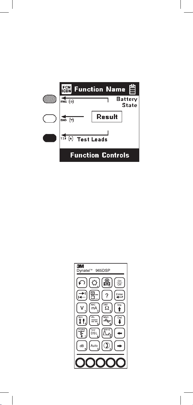
Screen
The 965DSP screen is a graphical LCD (Liquid
Crystal Display) that gives high resolution for
viewing text and graphics. The screen format is
similar to the following for most functions.
Test Leads
The Test Lead icons are shown on each of the
measurement screens. Each lead points to a color dot
on the front label that corresponds to the actual test
lead. The test leads have the labels “RNG” (ring),
“GND” (ground) and “TIP” (tip) for the US and
Canada. These labels correspond to “B”, Ground, and
“A” for other countries.
Keypad
The 965DSP Keypad has twelve yellow and red
“Control Keys” and twelve blue “Function Keys”.
Page 6
6
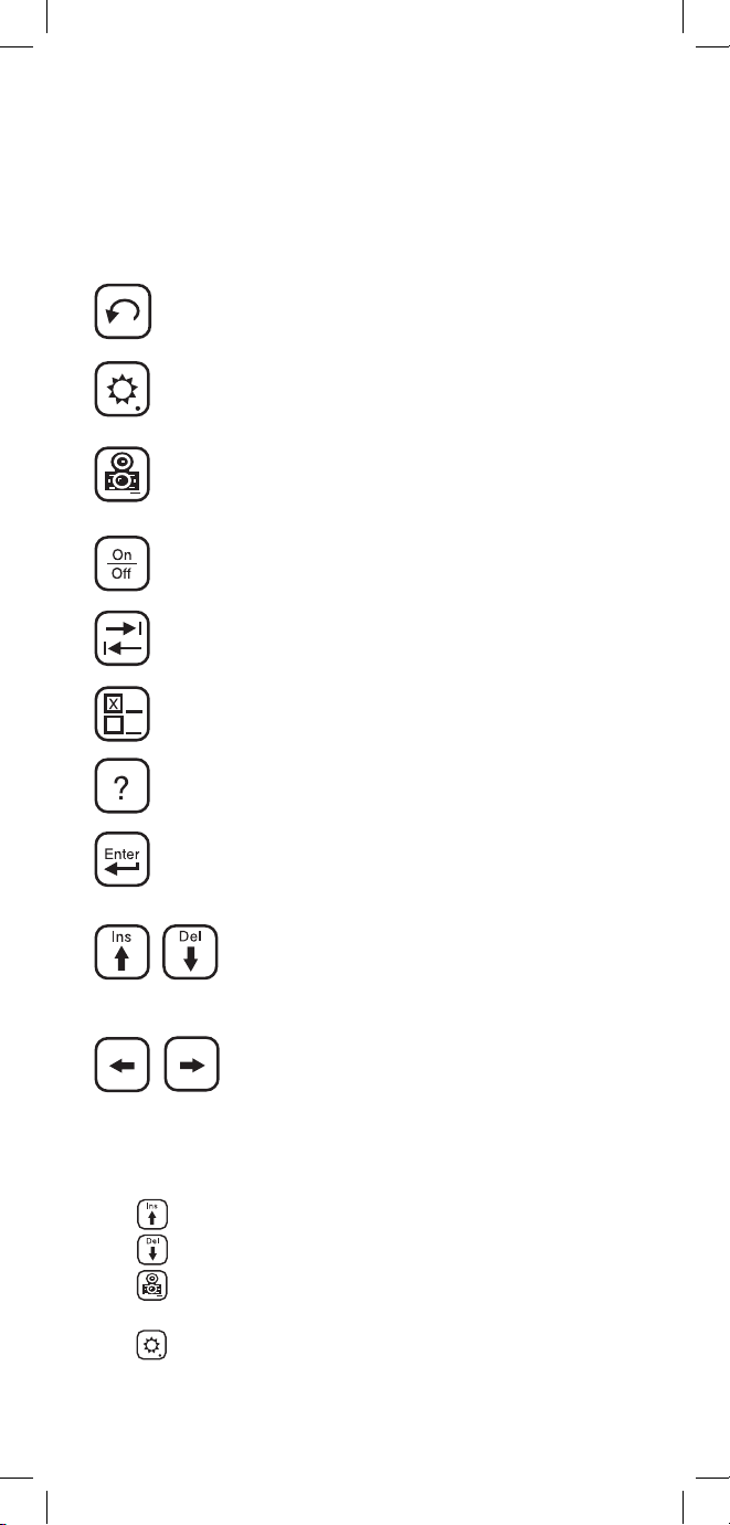
Control Keys
Use the red and yellow keys to control the actions and
the setup of the 965DSP and its functions. The active
control keys for each function are shown at the bottom
of the corresponding 965DSP screen.
Use the [Return] key to return to a
previous step in a function.
Use the [Contrast] key to adjust the
contrast or to turn the backlight on or off.
Use the [Save] key for saving Autotest results,
Single Trace TDR waveforms, and ADSL
Modem link information (/ADSL option only).
Use the [On/Off] key to turn the 965DSP
on or off (see also “Power Down Timeout”
on page 16)
Use the [Tab] key to select between
different options.
Use the [Setup] key to change the setup of
any function.
Use the [Help] key to get help with any
screen.
Use the [Enter] key to accept changes or
move to the next step in a function.
Use the [Up] and [Down] keys to
scroll to different menu options or
insert and delete characters when
editing.
Use the [Left] and [Right] keys to
move between different options or
move the TDR cursor.
Editing
Use the following keys when editing:
Use to insert a space to the left of the cursor.
Use to delete the character above the cursor.
Use to add a ‘dash’ in a telephone number or a
minus sign for signal levels or temperature.
Use to add one second delay for dialing.
Page 7
7
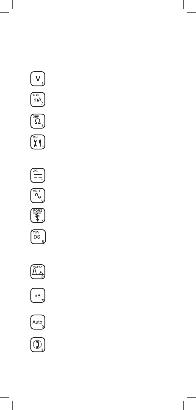
Function Keys
Use the blue keys to select the different test functions
in the 965DSP. The blue keys become number or
letter keys when editing.
Use the [Voltage] key to measure DC or
AC voltage.
Use the [Current] key to measure
loop current.
Use the [Resistance] key to measure
resistance.
Use the [Toolbox] key to access: Self-Cal,
Load Coils, Kick Test, Ringers, Special and
Ground Resistance, K-Test, Ohms/Distance,
Stored Results, Caller ID, and Splice Locate.
Use the [Opens] key to find the distance to
an ‘open’ circuit.
Use the [Tone] key to send tones for
pair identification or measuring loss.
Use the [RFL] key to find the distance
to a resistance fault on a pair.
Use the [DSL] key to access: ISDN datalink,
ADSL modem (/ADSL option only) and DSL
parametric measurements/Spectrum Analyzer
(/SA option only).
Use the [TDR] key to display the Time
Domain Reflectometer.
Use the [dB] key to measure Loss, Noise,
Longitudinal Balance, Wideband Loss, or
Level Trace.
Use the [Auto] key to perform a series of tests
on an Active, Inactive or Wideband pair.
Use the [Talk Set] key to dial numbers or
to place a phone call on a working pair.
L
Page 8
8
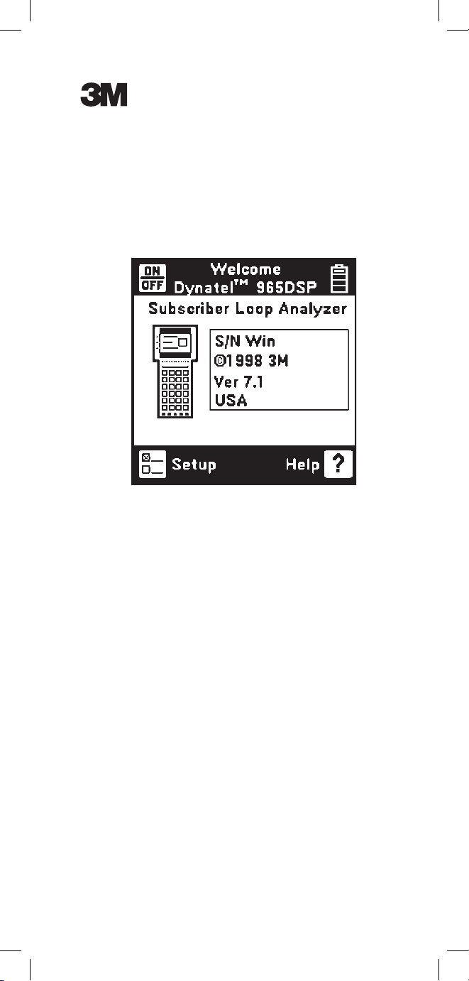
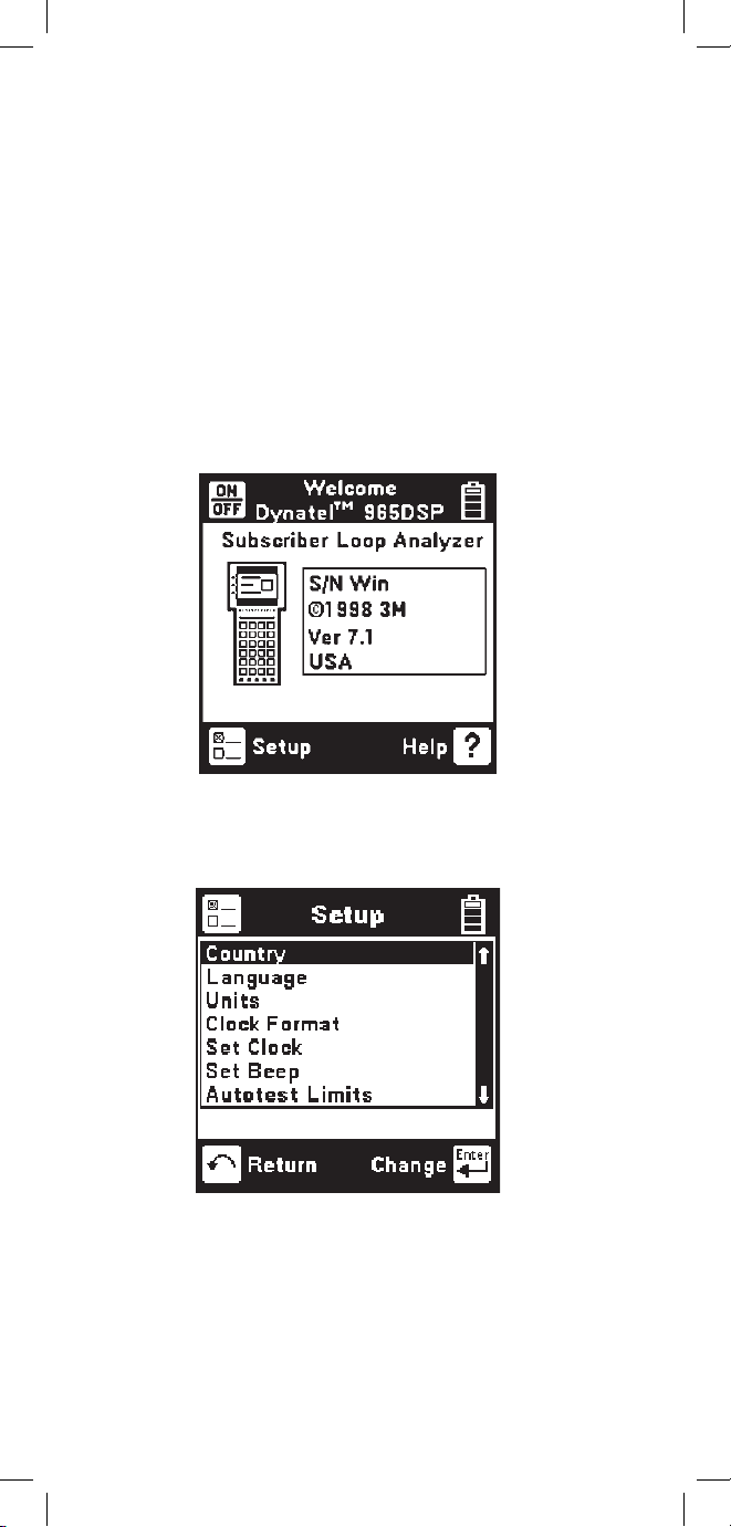
Welcome Screen
This is the screen that you see when you first turn
on the 965DSP. It shows the model name, installed
options, serial number, copyright year, software
version, and the selected country. The battery symbol
in the upper right-hand corner of the display gives an
indication of the approximate battery capacity. Each
bar represents one-quarter of the full capacity. If
the spare battery holder with the alkaline batteries
is installed in place of the NiMH battery pack, the
battery level will not be monitored and the battery
symbol will not be visible in the display.
Control Keys
Press [Setup] to go to the general setup screen from
the Welcome screen.
Use the [Up] and [Down] keys to highlight a menu
item: Country, Language, Units, Clock Format, Set
Clock, Set Beep, Autotest Limits, Printer, Power Down
Timeout, Edit Wire Gauge, Voltage Termination or User
Info. Press the [Enter] key to select the highlighted item.
Use [Return] to return to the Welcome Screen without
making changes.
Page 9
9
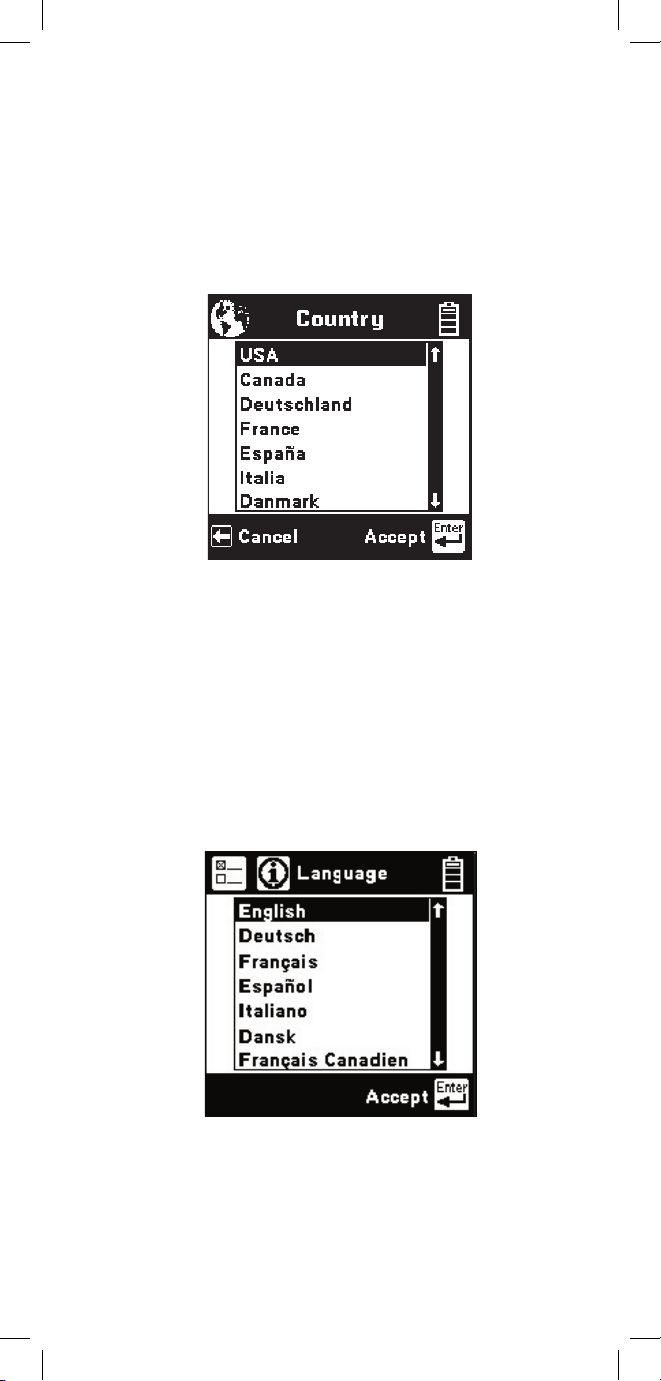
Country
Use the Country setup to configure the 965DSP
for a specific country. Selecting a new country will
configure the 965DSP with the setups for language,
units, clock format, wire gauges, and cable types for
that particular country.
Use the [Up] and [Down] keys to highlight a
Country. Use [Enter] to select a country. You will
be warned about changing country-specific default
values and asked to confirm or cancel your selection.
Language
Use the Language setup to change
only the
language in the 965DSP. Country-specific default
values are not affected.
Use the [Up] and [Down] keys to highlight a new
language. Use [Enter] to accept the changes and
return. Use [Return] to return to the Welcome Screen
without making changes.
Page 10
10
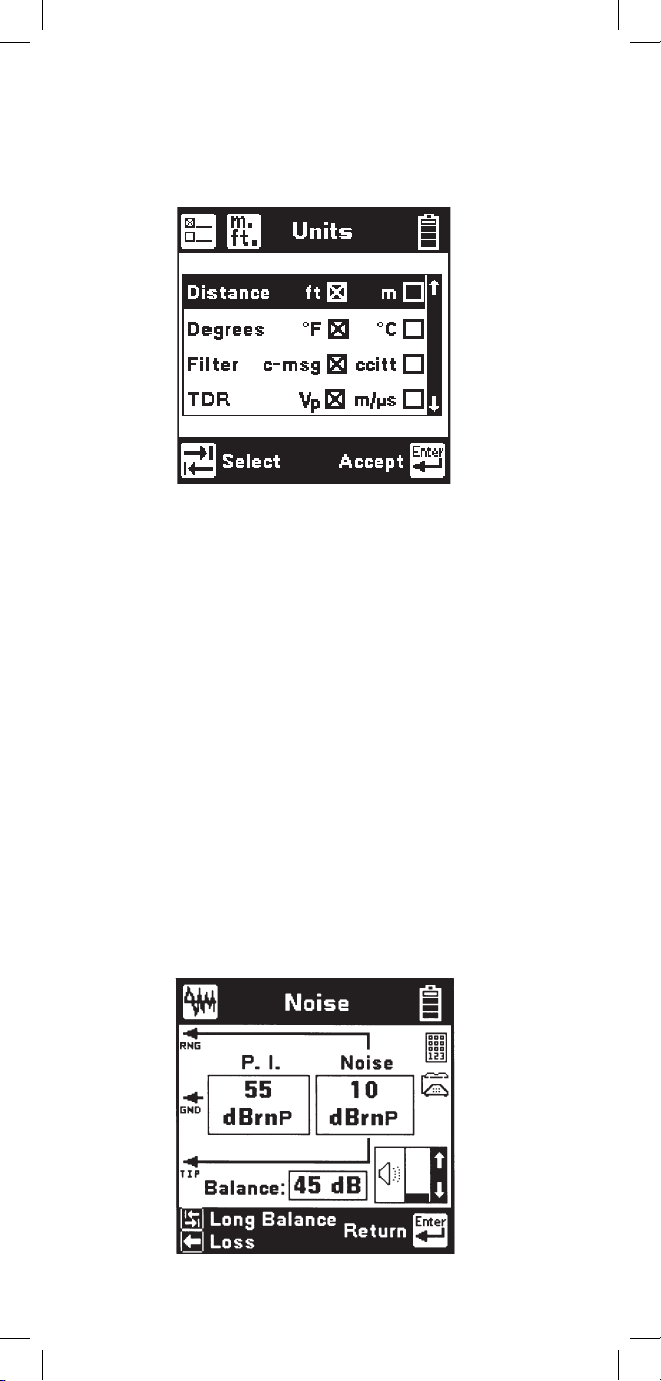
Use the [Up] and [Down] keys to highlight the option.
Use the [Tab] key to select the parameter for each unit
of measurement.
Distance: Feet or Meters. This affects all distances
displayed in the 965DSP.
Degrees: Fahrenheit or Centigrade. This affects all
temperatures used in the 965DSP.
Filter: C-Message or CCITT
. This affects the filter
used in the Noise function. Use the C-Message filter
in the US and Canada. Use the CCITT (also called
“Psophometric”) filter in all other countries.
The 965DSP also features a dBrnP filter for noise
tests in New Zealand. To set the default noise filter to
dBrnP, set Filter option to CCITT and Country to New
Zealand. This filter is used only in New Zealand; for
all other countries, the CCITT option uses a dBrnOp
filter. Noise test results will be displayed in dBrnP as
shown.
Units
Use the Units setup to change the units of
measurement for the 965DSP:
Page 11
11
TDR: Vp (Velocity of Propagation) or m/µS (meters
per microsecond). This affects the TDR “velocity of
propagation.” Use “Vp” in the US and Canada.
Use “m/µS” in other countries.
Use the [Enter] key to accept any changes and
return. Use the [Return] key to return to the
Welcome Screen without making changes.
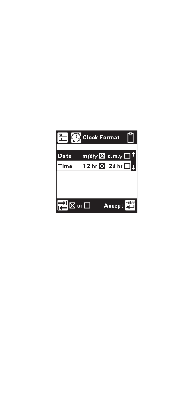
Clock Format
Use the Clock Format setup to change the format of
the clock. The clock is used for the timestamp and
datestamp in stored results.
Use the [Up] and [Down] keys to highlight either the
date or time. Use the [Tab] key to select the format
parameter.
Date: m/d/y (month/day/year) or d.m.y (day.month.
year). The m/d/y format is used in the US and
Canada. The d.m.y format is used in most other
countries.
Time: 12 hours or 24 hours. This affects the number
of hours displayed in the clock. The 12 hour clock
(with a.m. and p.m.) is used in the US and Canada.
The 24 hour clock format is used in most other
countries.
Use [Enter] to accept the changes and return. Use
[Return] to return to the Welcome Screen without
making changes.
Page 12
12
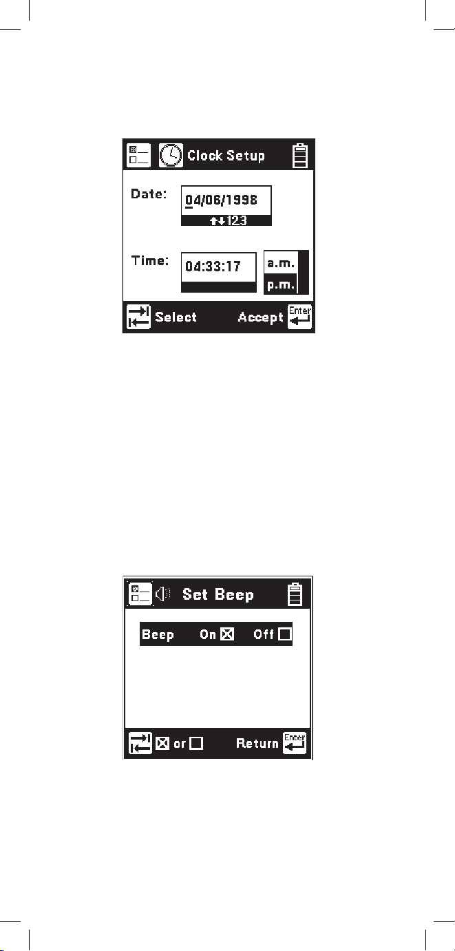
Set Beep
Use the Set Beep setup to turn the key beeps on or off.
Use the [Tab] key to toggle between on or off. Use
the [Enter] key to return.
Set Clock
Use the Set Clock setup to change the date and time.
Use the [Tab] key to select either the date, time, or
a.m./p.m. Use the [Left] and [Right] keys to select
the digit to change. Use the blue keys to enter the
values. Use the [Up] and [Down] keys to select
a.m. or p.m. Use [Enter] to accept the changes and
return. Use [Return] to return to the Welcome Screen
without making changes.
Page 13
13
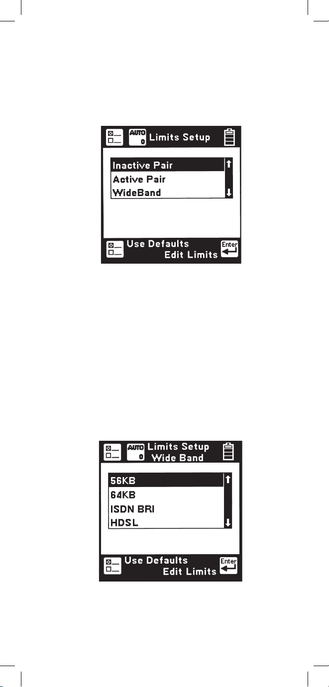
Autotest Limits
Use the Autotest setup to change the pass/fail
threshold values for the Inactive Pair, Active Pair
and Wideband Autotests.
Use the [Up] and [Down] keys to highlight the
desired Autotest parameters to modify. Press the
[Enter] key to select the highlighted choice or press
the [Setup] key to restore the factory default values
for the selected Autotest.
If Wideband is selected, a list of the available
wideband services is displayed. Use the [Up] and
[Down] keys to select the wideband service to
modify. Press the [Enter] key to select the
highlighted choice or press the [Setup] key to restore
the factory default values for the selected service.
Page 14
14
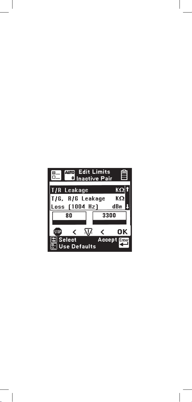
When the Inactive Pair, Active Pair or specific
Wideband service is selected, the Threshold Limits
screen will be displayed. This screen displays a list
of measurements performed in the selected Autotest
and the corresponding pass/fail limits for each
measurement.
The limits indicate the values at which the
measurement result passes (OK), is marginal (Yield
Sign) or is unacceptable (Stop Sign). The lower limit
threshold value is shown in the box on the left, the
upper limit in the box on the right.
If the test result value passes or is unacceptable, the
pass/fail result will correspond to the symbol under
the box (either Stop or OK). If the test result value is
between the upper or lower limit, the pass/fail result
will be marginal (Yield Sign).
Use the [Up] and [Down] keys to highlight the
desired test. Use the [Tab] key to move the cursor
to the limit value and enter the new value using the
blue keys. Press the [Setup] key to restore the factory
default values for the selected test. Press the [Enter]
key to accept the changes or the [Return] key to
ignore all changes and return to the Threshold Setup
screen. If invalid limits are entered, a warning screen
will be displayed. Press the [Enter] key to return to
Edit Limits screen and make appropriate changes to
the limits.
Page 15
15
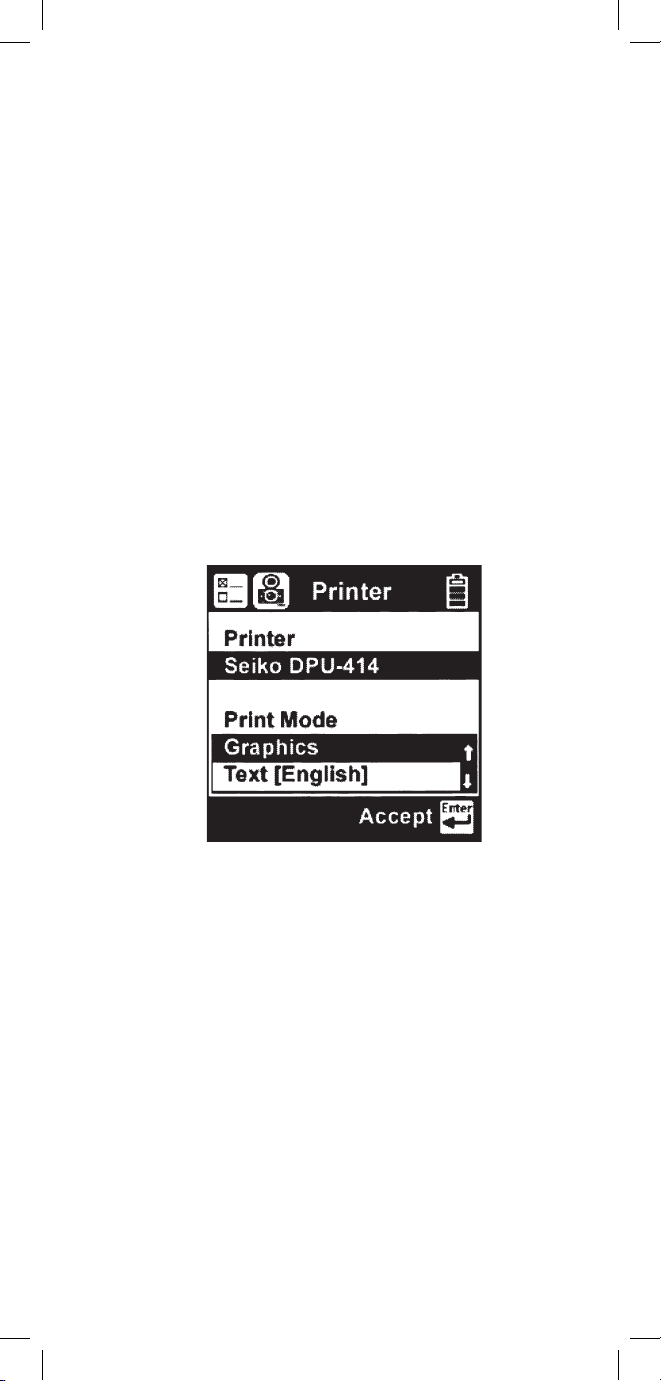
Printer
Use the Printer option to set the printer output type.
Use the [Up] and [Down] arrow keys to select either
graphics or text output, then press the [Enter] key to
accept your selection and return to the Setup menu.
A custom Loss Frequency (sometimes known as
the “Nyquist frequency”) can be set for use in the
Wideband Autotest. The custom Loss Frequency edit
screen is accessed by pressing the [Setup] key from
the startup screen, selecting Autotest Limits, then
Wideband. Press the [Enter] key to select a service
type. Select Loss Frequency, then use the [Tab] key
to edit. Enter the frequency value in KHz with the
blue numeric keys. Use the [Up] or [Down] arrow
keys to add or remove digits.
Page 16
16
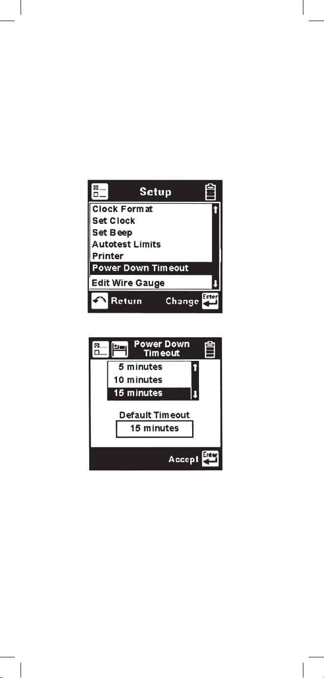
Power Down Timeout
To change the power down timeout, press the [Setup]
key from the Welcome screen, then select Power
Down Timeout. Use the [Up] and [Down] arrow keys
to select the desired timeout period, then press the
[Enter] key to set that period as the default. After a
period of inactivity equal to the default period, the
unit will beep, then automatically power down.
Page 17
17
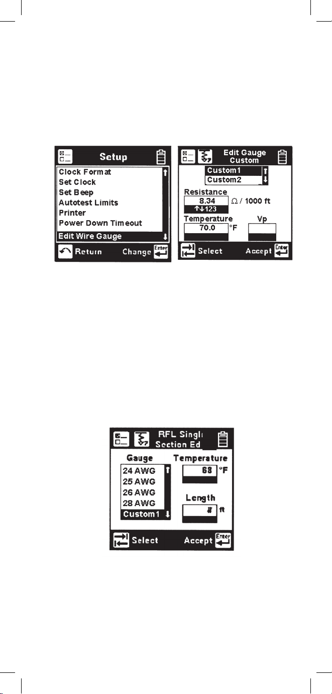
Edit Wire Gauge
This function allows you to set up custom wire
gauges to be used wherever the set uses a wire gauge
menu. Press the [Setup] key from the Welcome
screen, use the [Down] arrow key to scroll to Edit
Wire Gauge, and then press the [Enter] key to edit.
Name the custom configuration Custom 1 or Custom
2 by pressing the [Up] or [Down] arrow key. Use
the [Tab] key to select the values to be edited. Use
the [Left] and [Right] or [Up] keys to select the digit
to change. Use the blue numeric keys to enter the
values. Use [Enter] to accept the changes. Press the
[Return] key to return to the Setup menu without
making changes.
You can select this custom cable from any selection
menu (such as RFL), as shown.
Page 18
18
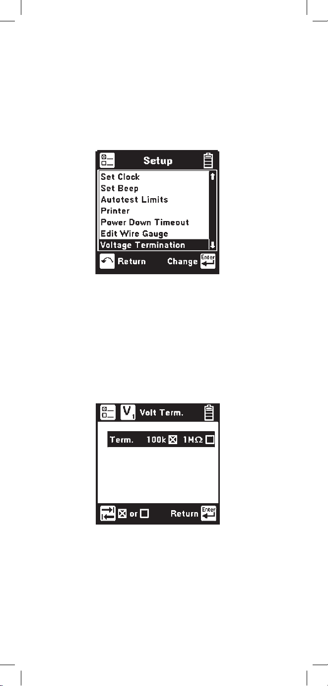
Voltage Termination (supported countries only)
This option allows you to select the input impedance
of the 965DSP digital voltmeter. Press the [Setup]
key from the Welcome screen, use the [Down] arrow
key to scroll to Voltage Termination, and then press
the [Enter] key to select.
The input impedance of the internal 965DSP
voltmeter is normally 1Mohm. However, some
legacy systems use voltage measurement systems
with input impedances of 100Kohms. This option
is provided to maintain measurement compatibility
with those systems. Use the [Tab] key to select the
desired termination and [Enter] to select.
Page 19
19
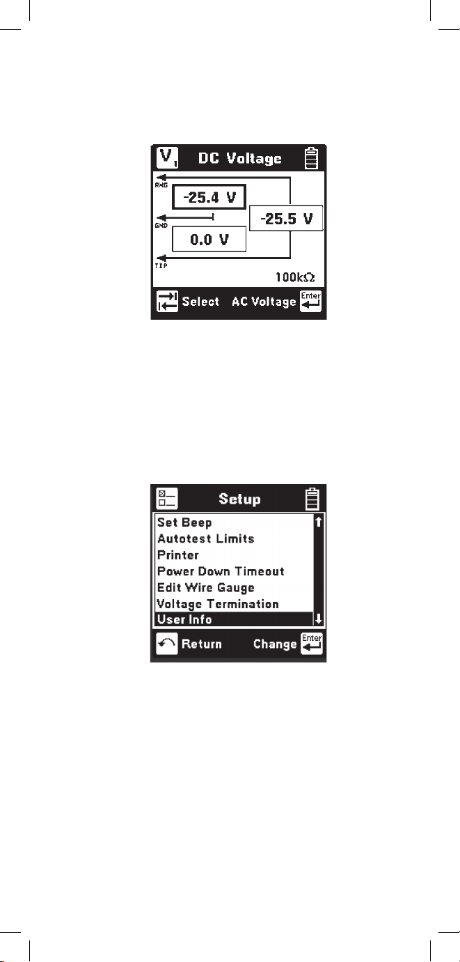
If 100Kohm termination is selected, the 965DSP
will display ‘100K’ on the voltage measurement
screen as indicated below.
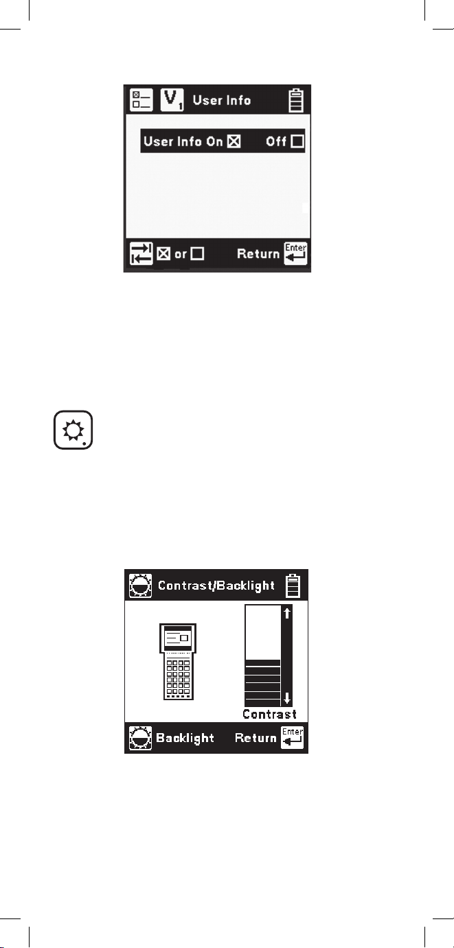
User Info
This selection allows you to add optional additional
information to your saved records. Press the
[Setup]
key from the Welcome screen, use the [Down]
arrow key to scroll to User Info, and then press the
[Enter] key to select.
Enabling User Info will cause the 965DSP to add
an extra user-editable screen during the results
save process. This screen has edit boxes for the
technician identification (‘Tech ID’) and the current
Job Number. These fields appear as part of the
Saved record when printed or viewed in PCLink.
Page 20
20
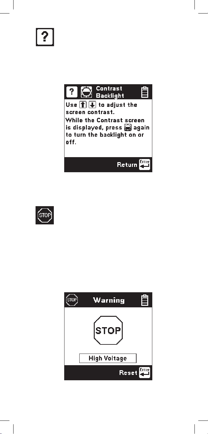
Contrast/Backlight
Press the [Contrast] key to display the contrast
screen. Use the [Up] and [Down] arrow keys to
adjust the contrast. Press the [Contrast] key again to
turn the backlight on or off. Use the [Enter] key to
return.
Use the [Tab] key to select ‘ON’ or ‘OFF’ and
[Enter] to save your selection. Once the User Info
option has been changed, the changes remain in
effect until you explicitly change them again.
Page 21
21
Help
Press the [Help] key at any time in any screen to get
help on that function.
Press the [Enter] or [Return] key to return to the
previous screen.
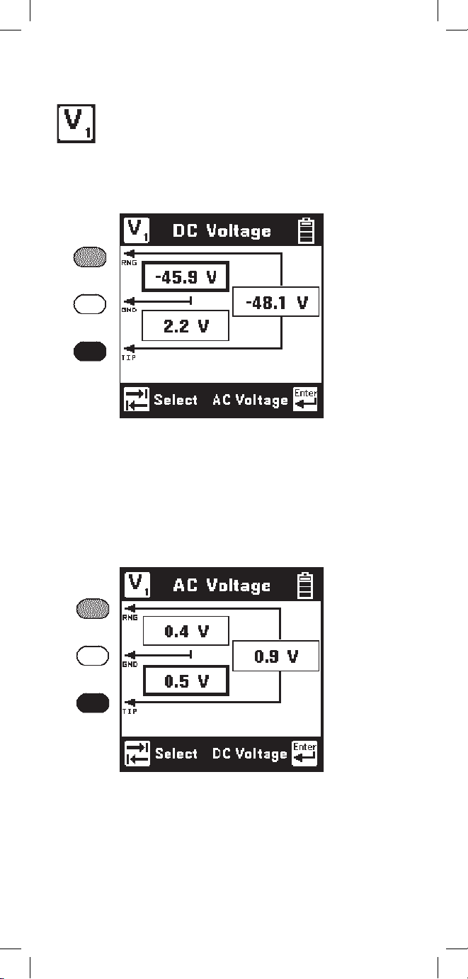
High Voltage
This screen indicates that a high voltage (120 Vac/
Vdc or greater) has been detected between the test
leads when not in the Voltage Mode. The 965DSP
has opened an internal relay to protect itself
from damage. Use standard safety practices for
disconnecting the test leads since high voltage may
be present.
Press the [Enter] key to restart the 965DSP.
Page 22
22
Press the [Tab] key to move to the next test lead
configuration. The highlighted reading is “live” and
the non-highlighted readings are the last values.
Press the [Enter] key to switch from the DC to the
AC voltage measurement.
Voltage
This function first measures and displays the DC
voltage between the red and black test leads.
Press the [Tab] key to move to the next test lead
configuration.
Press the [Enter] key to switch from the AC to the
DC voltage measurement.
Function Keys
Page 23
23
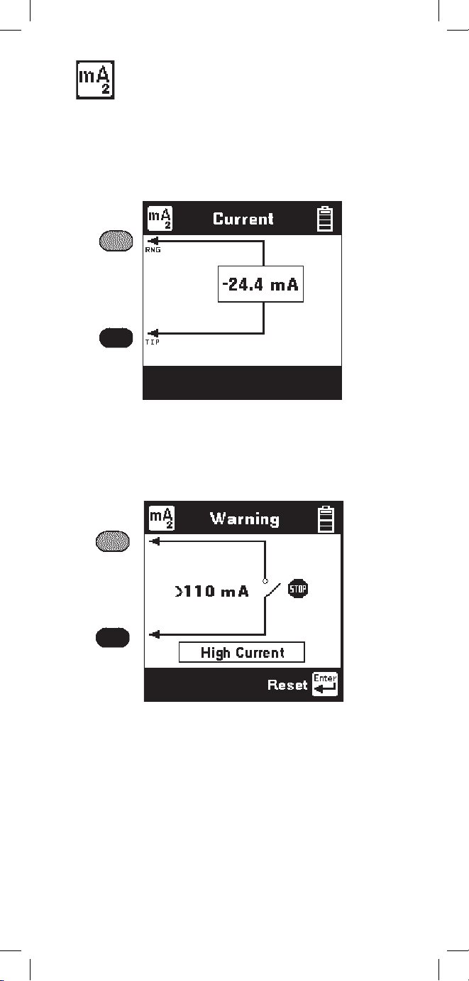
This screen indicates that a high current has been
detected between the test leads and that the 965DSP
has opened an internal relay to protect itself
from damage. Use standard safety practices for
disconnecting the test leads. Press the [Enter] key
to restart the 965DSP. Fix problems before restarting
the current measurement again.
Current
This function measures the DC current flowing
through a 430 Ohm resistor inside the 965DSP.
Connect the red and black leads to the pair to
measure loop current.
If the Current is greater than 110 mA, you will see
the following ‘Current Warning’ screen:
Page 24
24
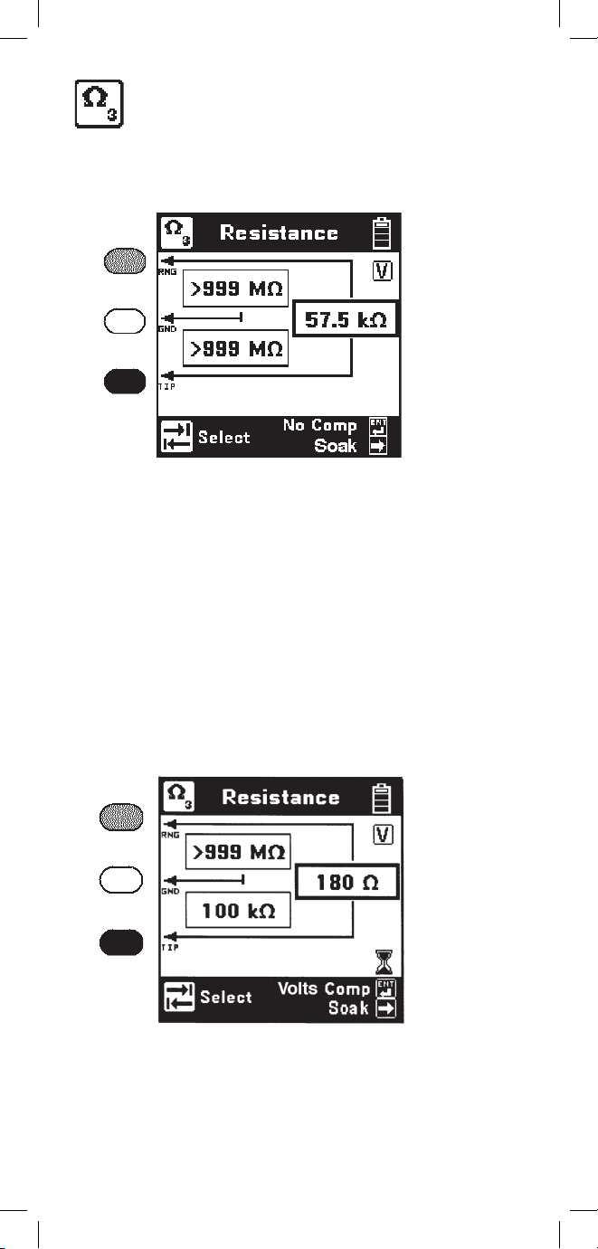
Resistance
This function first measures the resistance between
the red and black test leads.
Press the [Tab] key to move to the next test lead
configuration.
The “V” in the upper right corner of the screen
indicates that the resistance measurement
compensates for C.O. voltage on the line.
Press the [Enter] key to remove the voltage
compensation. Use this technique only if you
have first determined there is no DC voltage on
the pair (by using the Voltage function). The noncompensated measurement is slightly faster, but it
is not as accurate if there is voltage on the line.
The resistance measurement can be affected by
moisture on the test lead clips or terminal face. For
the most accurate measurement make sure that these
areas are dry.
Page 25
25
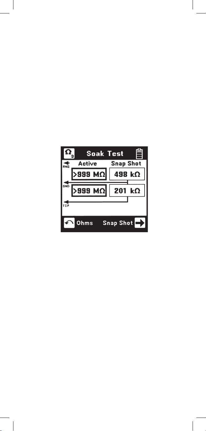
Soak Test
Use the Soak Test function to continuously measure
the non-compensated resistance tip to ground and
ring to ground simultaneously.
Press the [Right] arrow key to access the Soak test
from the Resistance screen. Connect the red and
black leads to an inactive pair. Connect green to
shield or ground. Use the [Right] arrow key to
refresh the measured resistance to the “Snap Shot”
area. This measurement will not be accurate if
there is foreign voltage or battery cross on the line.
Page 26
26
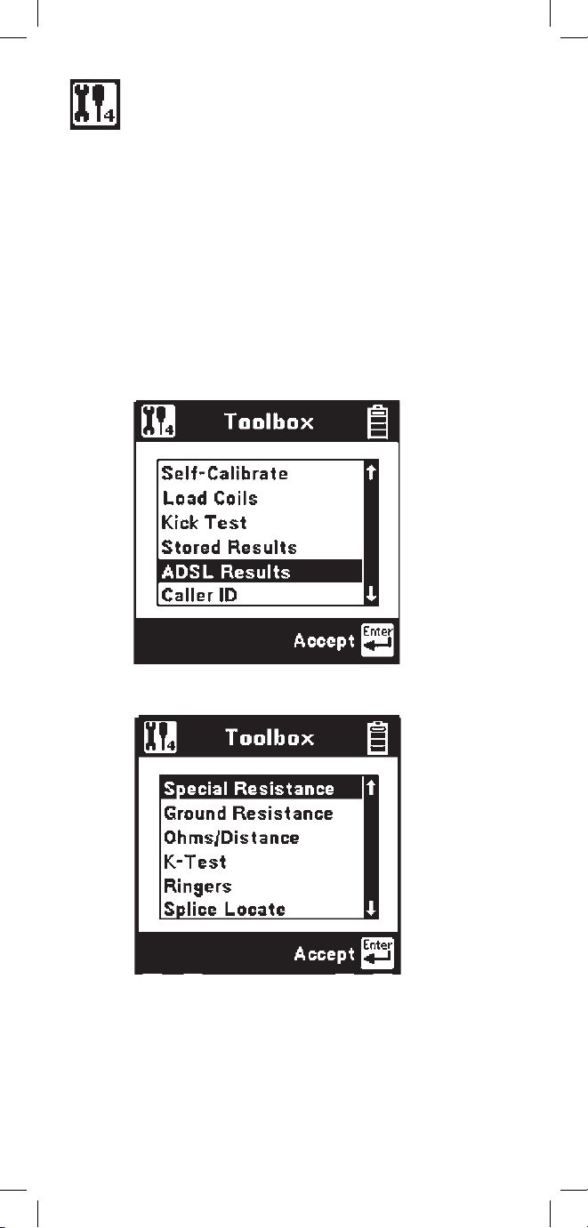
Toolbox
The “Toolbox” menu contains a selection of
functions depending on the options equipped in the
unit and the Country Code selected during Setup
(i.e. Caller ID is available only in North America and
ADSL Stored Results is only available on /ADSLequipped models). The menu displays only the
functions for which the unit is equipped. Only six
menu items are visible at any time. Use the [Up] and
[Down] arrow keys to move to the desired function,
then press the [Enter] key to accept the choice.
Note: The last item in the Toolbox menu
(Maintenance) is reserved for use only during
Factory setup and service of the 965DSP.
Page 27
27
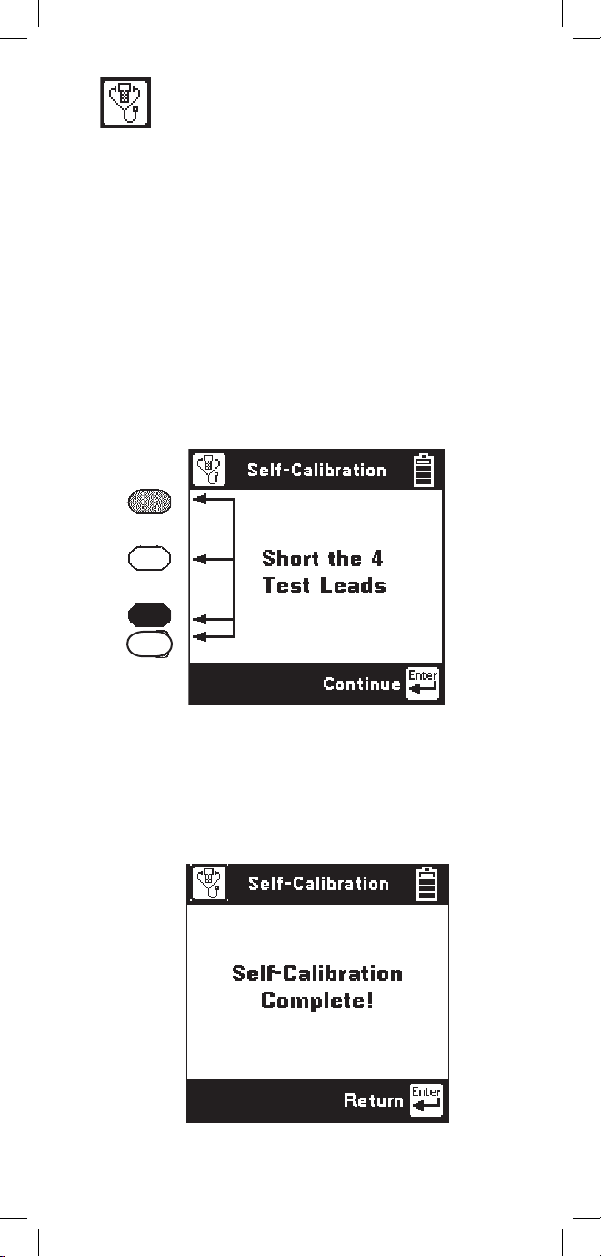
Self-Calibration
Use this function to calibrate the 965DSP anytime the
outside temperature changes by more than 35°F (20°C),
after changing the batteries, or anytime the battery pack
completely discharges. Calibrate the 965DSP at the
same temperature at which it will be used.
Note: Initiate a self-calibration prior to the very
first use of your 965DSP.
You will see the following screen as soon as you
select Self-Calibration from the Toolbox.
Short the red, green, black and yellow leads together
when prompted, then press [Enter] to continue.
The screen shows “Self-Calibration Complete” when
the calibration is done, or “Self-Calibration Failed”
if the calibration fails. In this last case, check the test
lead connections and try again.
Page 28
28
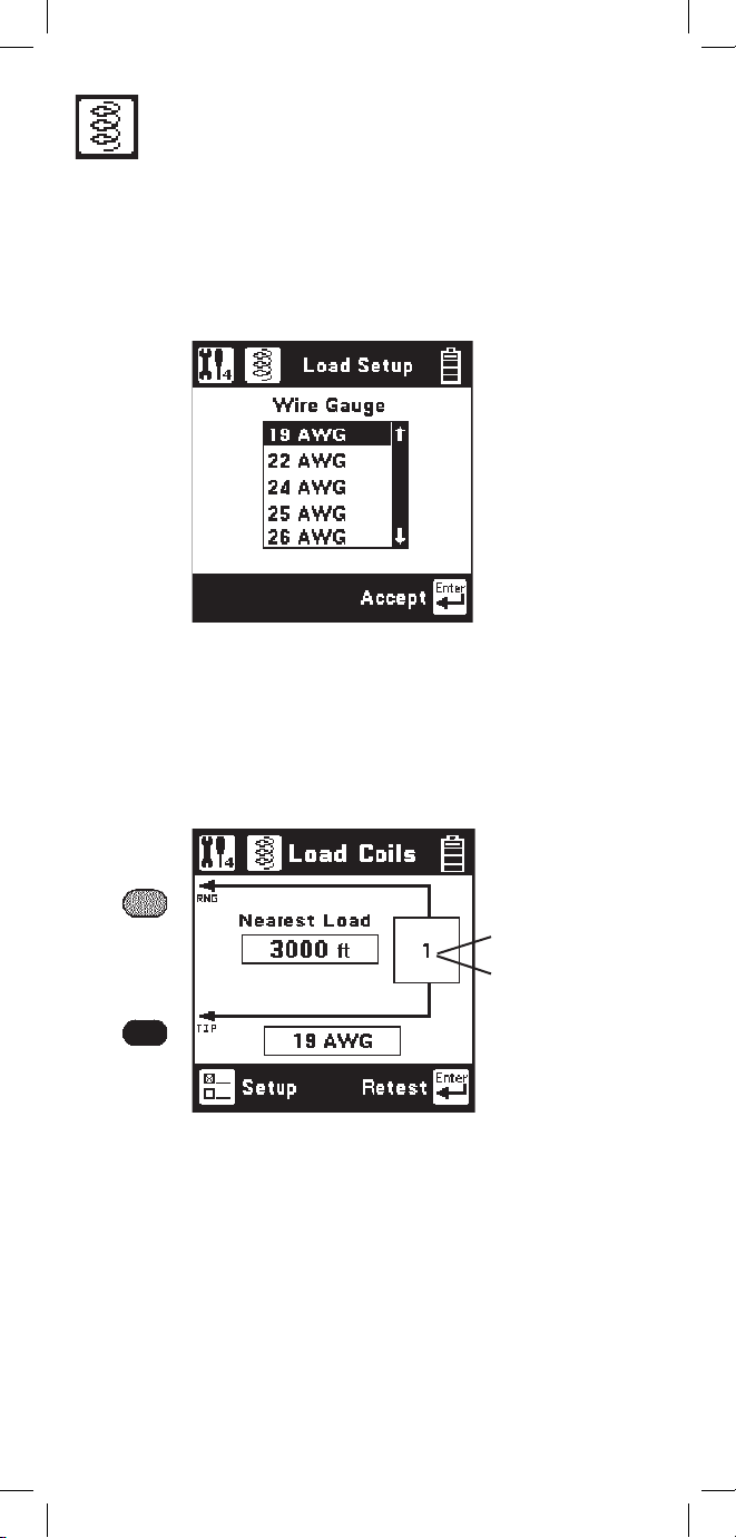
Load Coils
This function counts up to five load coils on the pair and
determines the distance to the first one. The distance
measurement requires that you specify the wire gauge
of the pair. This is done in the Load Setup screen. Use
the [Up] and [Down] arrow keys to highlight the correct
wire gauge. Use [Enter] to accept that choice.
The Load Coils screen will appear and an hour glass
will be visible at the bottom of the screen during the
measurement. When complete, the load coil count will
be visible in the box on the right and the distance to the
first load coil will be visible in the box labeled “Nearest
Load”. If no load coils are present the count will be 0 and
“Not Found” will be visible in the “Nearest Load” box.
After the test is done, press the [Enter] key to repeat the
load coil count. Press the [Return] key to return to the
Toolbox menu or press the [Setup] key to change the
wire gauge.
It is not necessary to have any particular length of
cable before the first load coil, but you must have at
least 3000 feet (1000 meters) of cable after each load
coil for the Load Coil function to count properly.
You may also use the TDR function to find the distance
to the first load coil on the pair.
Indicates
total number
of load coils
detected
Page 29
29
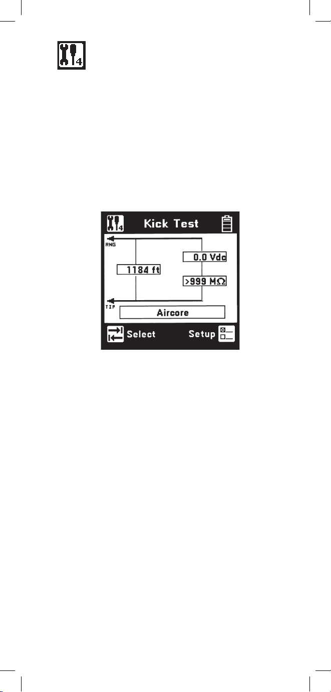
Kick Test
Use the Kick Test function to continuously measure
the voltage, resistance and capacitive length on tipring, ring-ground, and tip-ground. Connect the red
and black leads to the selected pair. Connect green
to shield or ground.
Press the [Tab] key to move to the next lead
configuration. Press the [Return] key to return
to the Toolbox menu or press the [Setup] key to
change the cable type.
Page 30
30
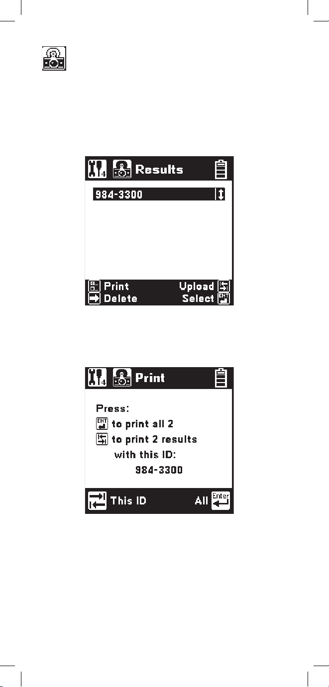
Stored Results
Use this function to view previously stored results of
the Autotest or TDR function. If no results have been
stored, “No Results Stored” will be visible on the
screen. If one or more test results have been stored,
the ID number for each will be displayed.
Press the [Setup] key to display the Print screen.
Press the [Enter] key to print all of the results. Press
the [Tab] key to print the results of the selected ID.
Press the [Return] key to return to the main Results
screen without printing.
Print Results
Page 31

31
Press the [Enter] key to delete all saved results.
Press the [Tab] key to delete the saved results of the
selected ID. Press the [Return] key to return to the
main Results screen.
Upload Results
Press the [Tab] key to display the Upload screen.
Uploading results requires the PCLink software
application and a computer.
Press the [Enter] key to upload all of the saved
results. Press the [Tab] key to upload the saved
results of the selected ID. Press the [Esc] key to
return to the main Results screen.
Press the [Right] key to display the Delete screen.
Delete Results
Page 32

32
Select Results
Use the [Up] and [Down] keys to highlight the
desired stored result. Press the [Enter] key to select
the highlighted result and display the stored results
list for that ID number by type (Autotest or TDR),
date and time.
Use the [Up] and [Down] keys to highlight the
desired stored result. Use the [Right] key to delete
the selected result. Use the [Setup] key to print the
selected result to a printer. Use the [Tab] key to
upload the selected stored test result to a PC.
Press the [Enter] key to view the results for the
highlighted selection. The results will be displayed in
the format used in the actual test.
To print the results to a printer, you must have a
compatible serial printer such as the Seiko DPU414-30B and a printer IR adapter cable (3M PN 261014-6888-7 available through 3M Communication
Markets Division Repair Center). The printer should
be configured for 9600 baud, 8 data bits, 1 stop bit,
no parity.
Uploading the test results to a PC requires an IR
adapter cable (3M PN 80-6109-9197-0) and the PC
Link Communications software package (available
through 3M Communication Markets Division
Technical Service Department).
Page 33

33
ADSL Results
Use this function to view previously stored ADSL
Modem test results (/ADSL option only).
Note: “ADSL Results” does not appear in the
Toolbox menu unless the /ADSL option is installed.
If no ADSL Modem test results have been stored,
“No Results Stored” will be indicated on the screen.
If one or more test results have been stored, the ID
number for each will be displayed.
Delete ADSL Results
To delete ADSL stored results, press the [Right] key
to display the Delete screen
Press the [Enter] key to delete all ADSL stored
results. Press the [Tab] key to delete the stored
results of the selected ID. Press the [Esc] key to
return to the main ADSL Results screen.
Page 34

34
Press the [Enter] key to upload all of the saved
ADSL results. Press the [Tab] key to upload the
saved results of the selected ID. Press the [Esc] key
to return to the main ADSL Results screen.
Select ADSL Results
To select a particular ADSL stored result for upload
or display, first use the [Up] and [Down] keys to
highlight the desired stored result. Press the [Enter]
key to select the highlighted result and display the
stored result list for that ID number by date and time.
Upload ADSL Results
To upload ADSL stored results to a computer, press
the [Tab] key to display the Upload screen.
Page 35

35
Use the [Up] and [Down] keys to highlight the
desired stored result. Use the [Right] key to delete
the selected result. Use the [Tab] key to upload the
selected result to a PC.
Press the [Enter] key to view the ADSL test results
for the highlighted selection. The results will be
displayed in the format used in the actual test.
To upload the ADSL test results to a PC, use an IR
adapter cable (3M P/N 80-6109-9197-0) and 3M PC
Link Communications software package Version 1.4
(or higher).
Page 36

36
Caller ID
This function detects the Caller ID signal sent on
the pair and displays date, time, the calling number,
the calling party name, the signal level, and the
message status. Certain result boxes may be blank if
the information is not available.
Connect the red and black leads to an active pair
and press the [Enter] key to start the test.
Note: The 965DSP Caller ID function is only
valid in supported countries. “Caller ID” does not
appear in the Toolbox menu for other countries.
Press the [Enter] key to retest or press the [Tab] key
for advanced Caller ID data.
This screen shows advanced information for
diagnosing Caller ID protocol problems. These
measurements are defined as follows:
Page 37

37
Ringing Length (A)
- The measured time duration of the first Ring
Burst.
Preseize Time (B)
- The measured time period between the first
Ring Burst and Channel Seizure.
Twist
- The ratio of the received Mark and Space
signal levels.
Seizure Bits
- The number of bits received during the
Channel Seizure (C) period.
Mark Time (D)
- The measured duration of the Mark period.
Postseize Time (F)
- The measured time duration between the Data
Packet (E) and the Second Ring Burst (G).
A B DC E F G
Tip/Ring
1st Ring
Burst
Channel
Seizure
Mark
Data
Packet
2nd Ring
Burst
Press the [Enter] key to return to the previous screen
or press the [Tab] key to view the Caller ID Raw
Data screen.
This screen displays a hexadecimal dump of all data
in the Caller ID packet. This data may be used for
analyzing compatibility problems between the Caller
ID format implemented by the switch and the format
implemented by the customer equipment.
Press the [Enter] key to return to the previous screen.
Page 38

38
Special Resistance
Use this function to measure the:
• Loop Resistance between the red and
green test leads.
• Resistance of each conductor connected
to the red and green test lead.
• Resistance Difference between the two
conductors.
Connect the red lead to one side of the pair.
Connect the green lead to the other side of the pair.
Connect the black to a reference wire.
Note that the “reference wire” can be a separate
wire or the shield of the cable.
Connect the Strap at a ‘far-end’ access point to the
two conductors of the same pair, and to the reference
wire.
Press the [Enter] key to start the test.
After the 965DSP displays the results, press the
[Enter] key to repeat the test.
Use the [Return] key to return to the Toolbox.
Page 39

39
Ground Resistance
Use this function to verify the protector ground
resistance compared to a Central Office (C.O.) using
the 965DSP and an active pair.
Connect the red lead to Ring of the active pair.
Connect the black lead to Tip.
Connect the green lead to Ground.
Press the [Enter] key to start the test.
After the 965DSP displays the results, press the
[Enter] key to repeat the test.
The 965DSP will show the message “Check Leads”
if the test leads are not connected as shown in the
screen diagram.
Note: The Ground Resistance function will only
work on pairs that are connected to C.O. switches
with Tip (or “A”) connected to ground.
Pairs connected to “floating” switches (such as the
AT&T #5ESS) will not give correct results.
Page 40

40
Ohms/Distance
Use this function to convert from Ohms to Distance
based on temperature and wire gauge.
Enter the value of Ohms, then press the [Tab] key to
select gauge or temperature. If you select “gauge,”
press the [Up] and [Down] keys to select the desired
gauge. If you choose “temperature,” enter the value
of the desired temperature using the blue keys.
Press the [Enter] or the [Tab] key when you are
ready to convert from Ohms to Distance. The screen
shows the total loop length, and half the length
(if you are measuring the distance to the end of a
strapped pair).
Press the [Setup] key to enter Distance instead of
Ohms. All control keys work the same as above
when entering distance.
Page 41

41
K-Test
Use this function to find the approximate distance
to a resistance fault when both wires in a single pair
are faulted at the same place, and a separate good
pair or a single loop conductor is not available.
Resistance Check
Before you start the K-Test measurement, use the
Resistance function to measure the resistance from
both sides of the pair to the reference conductor.
The resistance faults must be common to the
reference conductor.
One fault must be at least twice as “heavy” as the
other fault (e.g., 5k
Ω is twice as “heavy” as 10kΩ).
The sum of both faults must be at least 100 times the
loop resistance of the pair (for instance, if the loop
resistance is 50
Ω
, the fault sums must be 5kΩ or
greater).
The K-Test first makes a measurement with the farend “open” (the strap disconnected).
And then repeats the measurement with the far-end
“closed” (the strap connected).
You may choose to use a “far-end switch” to open
and close the far-end. The 3M KM Box Model 1162
is recommended for this application. The 965DSP
will automatically send tones on the blue and yellow
leads to communicate with the 3M KM Box (far-end
switch).
The far-end can be manually opened and shorted
during the test. However, be aware of timeout issues
that may occur.
K-Test Setup
The K-Test Setup screen is identical to the RFL
Setup screen. Press the [Setup] key to change the
gauge or temperature.
Page 42

42
Connect the red lead to R2, the wire to the heavier
fault (lowest resistance value). Connect the green
lead to R1, the wire with the lighter fault resistance
(the highest resistance value).
Connect black to the reference wire (either the shield
or another conductor in the cable).
If you are using a far-end switch (3M KM Test
Switch Model 1162) to open and close the far-end,
you should also connect the blue and yellow leads to
the pair under test. Also, connect the far-end switch
to the pair under test at the far-end access point.
Press the [Enter] key to start the test.
If you are using a far-end switch, the 965DSP will
automatically send a command to the device to open
the far-end.
Open Far-end
Start the K-Test by opening the far-end.
Page 43

43
K-Test Hookup: Close Far-End
The 965DSP will display the following screen if it
does not detect any hook-up errors during the “Open
Far-End” test.
The “Open Ratio” value displayed on the screen
is the ratio of R1/(R2+R1) times 100. This value
is used by some companies as part of the K-Test
measurement. It is not needed to actually calculate
the distance to the faults.
Note that the above screen indicates that the fault
resistances (R1 and R2) are OK!
If you are using a far-end switch, the 965DSP will
automatically send a command to close the farend. If you are not using a far-end switch, you or
somebody should manually short (or “strap”) the farend before you continue. Press [Enter] to continue
the K-Test.
Page 44

44
K-Test Results
The 965DSP will display the following screen if
there are no problems with the “Close Far-End”
portion of the test:
The 965DSP displays the Resistance to Strap (RTS),
Resistance to Faults (RTF) and the Resistance Strap
to Faults (RSTF).
The 965DSP displays the open and closed fault
ratios. These values are used in some countries as
part of the K-Test.
Use the [Tab] key to display distances to the faults
and strap instead of resistance.
The 965DSP displays the last wire gauge and
temperature selected. Use the [Setup] key to change
either the wire gauge or the temperature used for the
conversion from resistance to distance.
Use the [Left] arrow key to repeat the K-Test on the
same pair. The screen keeps count of the number (in
the lower right) of times the test is repeated.
Use [Enter] to see a summary of up to five K-Test
measurements.
Page 45

45
K-Test Summary
If you press the [Enter] key in the previous screen,
the 965DSP will display the following summary of
up to five K-Test results:
The 965DSP displays the Resistance to Faults
(RTF), Resistance Strap to Faults (RSTF), and
the Resistance to Strap (RTS) for up to five
measurements.
The 965DSP also displays the average value of the
five measurements. In general, the average value
of many readings is more accurate than a single
reading.
Use the [Enter] key to display the last K-Test result.
Use the [Tab] key to select distance instead of
resistance. Use the [Setup] key to change the wire
gauge or the temperature used for the conversion
from resistance to distance.
Page 46
46
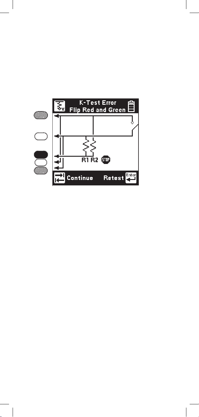
K-Test Error: Flip red and green
The 965DSP will first make a measurement to
verify that the heavier fault is connected to red and
the lighter fault is connected to green.
If the size of faults is reversed, you will see the
following screen: K-Test Error
This screen indicates that the connections to the red
and green leads are reversed and the leads should be
swapped or “flipped.” Leave the black lead connected
to the reference wire.
Press the [Enter] key to retest the connection
after swapping the leads, or press the [Tab] key to
continue without retesting the connection.
Page 47

47
K-Test Error: R1<2*R2
The 965DSP checks to see that the fault on the
green lead is at least twice the value of the fault on
the red lead. This screen indicates that the ratio of
the faults is too low.
Press [Enter] to return to the initial “K-Test Hookup:
Open Far-End” screen. You may also elect to
go to the Resistance function and re-measure the
resistances before repeating the K-Test.
Page 48

48
K-Test Error: Rloop > 7kΩ
The 965DSP checks to see if the resistance of the
loop is less than 7k
Ω. If the resistance is greater
than 7kΩ, then the distance to strap may be too
long, the strap is not connected, or the far-end
switch did not switch properly.
Check the connections, and press [Enter] to repeat
the “Close Far-End” portion of the test.
Page 49

49
K-Test Error: R1+R2<100*Rloop
The 965DSP checks to see that the sum of the faults is
more than 100 times the loop resistance. The 965DSP
will display the following screen if the sum of the faults
is less than 100 times the loop resistance.
Press [Tab] to continue even though the fault values
are too low. This may result in reduced accuracy of
the measurement.
Press [Enter] to repeat the K-Test, starting with the
“Open Far-End” screen. You should first find a new pair
in the faulted cable with higher value fault resistances.
Page 50

50
Pressing the [Tab] key again will return the screen to
Ringers Capacitance. Press the [Enter] key to repeat
the test.
Ringers
This function measures the capacitance associated
with one or more ringer circuits on the line or the
equivalent number of ringers (1 ringer = 0.47 uF).
Either the Ringers Capacitance screen or the Ringers
(equivalent) screen will be displayed depending on
which was last selected. During the measurement an
hour glass will be visible at the bottom of the display.
When the measurement is complete, the RingGround, Tip-Ring and Tip-Ground capacitance will
be displayed. To display the equivalent ringer count,
press the [Tab] key.
Page 51
51
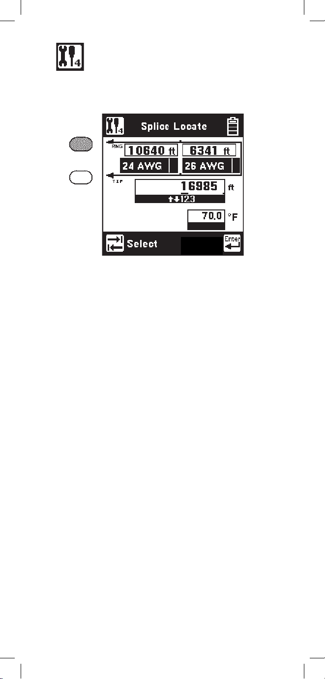
Splice Locate
Use this function to find the location of a splice in
two sections (of different wire gauges) of cable.
If you select either section, use the [Up] and [Down]
keys to select the wire gauge. You may NOT use the
same gauge for both sections.
If you select either the DTS or the temperature, use
the blue keys to enter the appropriate value.
Press [Enter] when you have connected the 965DSP
and have entered the correct gauges, temperature and
distance to strap.
The screen will display the distance to the splice and
the distance from the splice to the strap.
Press [Enter] to repeat the test after the results have
been displayed on the screen.
Start
Connect the red and green leads to the pair.
Connect the strap at the far-end across the pair.
Use the [Tab] key to select either: 1) the first section
wire gauge, 2) the second section wire gauge, 3) the
Distance to Strap (DTS), or 4) the temperature.
Page 52

52
Opens
This function measures the distance to a complete
“open” on a pair based on a selected cable type.
“Opens” is more accurate if other cable pairs are
active. If other pairs are not active, short at least
30% of the inactive pairs to the cable shield.
The TDR function should be used to determine
distance to a “partial” open.
The 965DSP will first measure the “open” distance
between green and black. Use the [Tab] key to move
to the next lead configuration.
Press the [Setup] key to change the Cable Type, or to
select Capacitance.
Press the [Up] or [Down] keys to move to the desired
cable type. Press the [Enter] key to accept the choice
and return to the main Opens screen. Press the
[Return] key to return without changing the cable type.
Page 53

53
Press [Enter] to accept the changes and return to the
Opens Setup screen. Press [Return] to return without
making changes.
First enter the red to black capacitance per unit
distance using the blue keys. This is also called
“Mutual” capacitance.
Then press [Tab] and use the blue keys to enter
the capacitance/distance for black to green. This
capacitance is sometimes called the “Pair to
Shield” or “Pair to Ground” capacitance.
Press the [Tab] key to edit the “Custom” cable type.
Press the [Setup] key to edit the “Calibrated Cable”
type.
Edit Custom
Use this function to change the value of the “Custom
Cable” type. Select Custom Cable if you are using a
specific type of special cable on a regular basis.
Calibrate to Cable
Use this function to measure the capacitance of a
known good pair within a cable of known length.
This value can be used as a ‘Calibrated Cable’ (or
‘reference’) to find the distance to an ‘open’ on the
same or similar cable.
Connect the red and black leads to the pair (to be
used as a reference) and green to shield.
Page 54

54
Enter the length of the section and press the [Enter]
key to measure the capacitance.
The 965DSP will then display the measured
capacitance/distance for the reference pair.
Press the [Enter] key to accept the results as the
“Calibrated Cable” and return to the Setup screen.
Press [Return] to return without saving.
The Yield Sign
(if shown) indicates that the Ring
(or B) - Ground capacitance differs from Tip (or A)
- Ground by greater than 5%.
Page 55

55
Tone
Use this function to send a tone on a pair. Use the
[Up] and [Down] keys to select the desired tone. Note
that there are ten tones. Use [Up] and [Down] to
scroll through the tone selections.
There are three types of tones: ID Tone for pair
identification and coiling, Precision Tone for 600
Ω loss measurements, and High Frequency Tone
for 135
Ω wideband loss measurements. The ID
Tone is always sent as an interrupted (beeping) tone.
The other tones are continuous tones. The 965DSP
automatically goes off-hook when an ID tone is sent.
First 5 frequencies
Press the [Enter] key to send the selected tone. The
send tone screen varies, depending on which tone
has been selected; ID Tone, Precision Tone, or High
Frequency Tone.
Second 5 frequencies
Page 56

56
Precision Tone
ID Tone
High Frequency Tone
The volume of the tone heard in the 965DSP speaker
may be adjusted for the ID Tone and the Precision
Tone. No tone is heard in the speaker for the High
Frequency Tone.
Page 57

57
Press the [Setup] key to edit the selected tone and go
to the following screen:
Use the [Tab] key to select the tone type, frequency
or level. Use the keypad to change the values.
The frequency range is 200 to 1000 Hz for ID Tones,
200 to 19999 Hz for Precision Tones, and 20 KHz to
1200 KHz for High Frequency Tones.
The output range for Precision Tones is -20.0 to
+1.0 dBm. The output level for High Frequency
Tone is fixed at 0 dBm. The ID Tone output is set at
maximum level.
Press the [Enter] key to accept the changes and
return to the Tone Menu screen.
Press the [Return] key to return without making
changes.
Press the [Up] and [Down] keys to adjust the
volume. The output impendance for the Precision
Tone (600
Ω) and the High Precision Tone (135 Ω)
will be visible in the lower left side of the screen.
Use [Enter] to stop sending.
Note: The volume control does not affect the level
of the tone sent on the pair.
Page 58

58
RFL (Resistance Fault Locate)
Use this function to locate a Resistance Fault on a
pair or on a single conductor.
There are two possible hookups: Separate Pair or
Single Pair. Use [Tab] to switch between the two
hookups.
Separate Pair (This is the preferred hookup
)
You must first use the Resistance function to
determine the faulted conductor and identify a
separate good pair (a pair with no faults).
Once you identify the wires, connect the shorting
strap at the ‘far-end’ with the common (red) clip to the
faulted conductor and the black clips to the two wires
of the separate good pair.
Press the [RFL] key and select “Separate Pair” by
pressing the [Tab] key.
The hookup screen will show the last selected wire
gauge and temperature. Use the [Setup] key to
change the gauge, temperature, or to enter a known
distance to Strap.
Note: Either the temperature or length (distance
to Strap) must be selected as unknown. Enter the
pound (#) sign as the unknown.
Page 59

59
During the measurement a bar graph of the
measurement null voltage for RTS and then RTF will
be visible at the bottom of the screen.
Connect the red test lead to the faulted wire. Connect
the black Lead to the reference. (The reference is the
return path for the fault and can be the shield or another
wire in the cable.) Connect the green and yellow test
leads to the separate good pair.
Press the [Enter] key after you make the above
connections.
If no errors in the hook-up are detected, the 965DSP
will begin the measurement and go to the results screen.
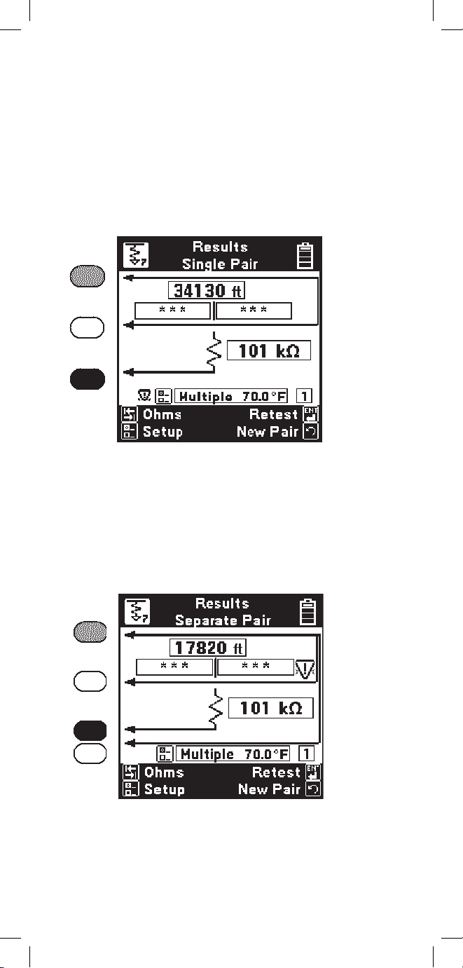
The results at the top of the screen indicate the
“Distance to Strap”. The results on the second line
indicated the “Distance to Fault” and the “Distance,
Strap to Fault”.
Page 60
60
The screen shows the fault resistance beside the
resistor symbol. The wire gauge, temperature and
section number are displayed above the bottom bar.
If the Yield Sign
shows beside the results, this
indicates a possible marginal result (due to noise or
other line conditions).
Press [Tab] to show readings in Ohms instead of
distance. Press again to return to distance. Press
[Enter] to repeat the fault locate on the same pair or
the [Return] key to test a new pair. Press [Setup] to
change the Gauge or Temperature.
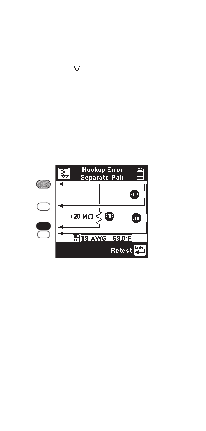
If there is a problem with the connection, you will
see the “Hookup Error” screen.
There are three possible hookup errors: 1) the fault is
greater than 20 M
Ω, 2) the red/green strap is bad, or
3) the red/yellow strap is bad.
The screen will show the combination of errors that
have been detected. Correct the errors and press the
[Enter] key to repeat the hookup test.
Page 61

61
RFL Single Pair
Use the RFL Single Pair hookup when only one wire
in a pair is faulted and a separate good pair is not
available.
Use the Separate Pair hookup for all cases in
which a separate pair is available; it is always the
preferred method.
You must first use the Ohms function to identify
a faulted conductor in a pair and to verify that the
other conductor is not faulted.
Once you identify the wires, strap the faulted and
good conductor together at the far-end.
Press the [RFL] key and select “Single pair” using
the [Tab] key.
Verify correct wire gauge and temperature. Use the
[Setup] key to change the gauge or temperature.
Connect the red test lead to the faulted conductor
in the pair. Connect the green test lead to the good
conductor of the same pair. Connect the black Lead
to the reference. (The reference wire could be the
shield or another wire in the cable.)
Press the [Enter] key after you have made the above
connections. If the connections are OK, the 965DSP
will go directly to the RFL results screen.
Page 62

62
During the measurement a bar graph of the
measurement null voltage for RTS and then RTF will
be visible at the bottom of the screen.
The results at the top of the screen indicate the
“Distance to Strap”. The results on the second line
indicate the “Distance to Fault” and the “Distance,
Strap to Fault”.
The screen shows the fault resistance beside the
resistor symbol. The wire gauge, temperature and
section number are displayed above the bottom bar.
Press [Tab] to show readings in Ohms instead of
distance. Press again to return to distance. Press
[Enter] to repeat the fault locate using the same
Distance to Strap or the [Return] key to test a
new pair. Press [Setup] to change the Gauge or
Temperature.
Page 63

63
RFL Setup: Single Section
Use the RFL Setup to change Wire Gauge and/or
the cable Temperature or enter a known Distance to
Strap.
Press the [Setup] key to display the current settings.
There are two possible single pair hookup errors:
1) the Fault is greater than 20 MΩ, or
2) the red/green strap is bad.
The screen will show the combination of errors that
have been detected. Correct the errors and press the
[Enter] key to repeat the test. The measurement will
begin and the results screen will be displayed.
If there is a problem with the connections, you will
see the “Hookup Error” screen.
Page 64

64
Press the [Tab] key to select either the wire gauge
menu, cable temperature, or length (distance to
Strap) for editing.
If you select the Wire Gauge menu, press the [Up]
and [Down] keys to select the desired gauge.
If you choose Temperature or Length, enter the
new value using the blue numeric keys. Either
the Temperature or Length must be specified as
unknown by entering a “#” for the value.
Note: Always enter the temperature of the cable,
not the ambient temperature.
Press the [Enter] key to accept the changes and
return to the previous screen. Press the [Return]
key to return without saving the changes. Press the
[Enter] key again to return to the hookup screen.
RFL Setup: Multi-Section
Use RFL Multi-Section when there is more than one
section of cable with different wire gauges between the
near-end and the far-end. Single or Separate pair hookup
can be used in RFL Multi-Section.
While in the “Hookup Single Pair” or “Hookup
Separate Pair” screen, press the [Right] key to select
Multi Section. The wire gauge displayed near the
bottom of the display will be replaced by “Multiple”.
Then press the [Setup] key to go to the Setup screen.
The following is an example of the Setup screen for two
sections. Note that the screen shows a “#” to indicate
the distance is unknown.
Page 65

65
Note: Enter the temperature of the entire cable.
You may not enter separate temperatures for each
section.
Enter “#” for the temperature if it is unknown and
you want the 965DSP to compute the temperature.
The Multi-Section screen shows a summary of up
to six sections, and the common temperature for all
sections.
One cable parameter (a section length or temperature)
should be left as unknown. If a value is entered for
all parameters, temperature will be treated as an
unknown and will be calculated by the 965DSP.
Press the [Tab] key to select either the Section
Information or the Temperature for editing. Press the
[Left] key to clear all of the Section Information.
Edit Temperature
If the Temperature is known, enter the value of
the desired temperature using the blue keys as a
numeric keypad.
Page 66

66
Press [Enter] to accept the changes for the section
and return to the previous RFL Setup screen. Press
[Return] to return without making changes.
Edit Section Information
If you choose to edit the Section information (gauge
or distance) for any of the six sections, use the [Up]
and [Down] keys to select the desired section, then
press the [Setup] key to edit the selected section.
Press the [Tab] key to select either the Wire Gauge
menu or the Section Length.
If you select the Wire Gauge menu, press the [Up]
and [Down] keys to select the desired gauge.
If you select Section Length, enter the length of the
section using the blue keys.
Note: If you are using less than the maximum of
six sections, the distance of all unused sections is
set to zero feet or meters.
You will see the message “Enter ‘#’ if unknown”
below the Edit Section Length if the temperature or
another section has not previously been declared as
unknown. Declare a section “unknown” by entering
a “#” in the length box.
Page 67

67
Press the [Tab] key to display the results in ohms.
Press the [Enter] key to retest the same pair or the
[Return] key to test a new pair.
RFL Multiple Results
There are two possible formats for displaying the
results of an RFL Multiple measurement:
1) The temperature is known. In this case the screen
will show the calculated Distance to Strap (the
sum of all sections) in the main result box and the
“Distance to Fault”on the left on the next line and
the “Distance Strap to Fault” on the right on the
same line. The screen also shows the number of the
faulted section at the lower right side of the screen.
Page 68

68
2) The temperature is unknown. In this case the
screen will show the entered Distance to Strap (or
the sum of all sections) in the main result box, and
will show the calculated temperature at the bottom.
The screen also shows the number of the faulted
section at the lower right side of the screen.
If the calculated temperature is much different than
the expected temperature, you should suspect that
the entered DTS or the entered section information is
incorrect.
Page 69

69
RFL Errors
One of several errors may occur during an RFL
multi-section measurement.
If the RFL measurement terminates due to a timeout, a “Yield Sign” will be displayed next to the
DSTF or RSTF result, as shown. This indicates
that the results may not be accurate. This could be
caused by excessive noise on the pair.
The multi-section screen will now show the
computed length of the unknown section.
Use [Tab] to convert between Ohms and Distance.
Use [Setup] to display the RFL Multi-Section Setup
screen again.
Page 70
70
If the temperature is known and the total of the
specified section lengths is greater than the measured
distance to strap, then the calculated unknown
section length would be negative. This will cause a
“Yield Sign” to be displayed to the left of the setup
boxes and “***” to be displayed in the
“Distance to Fault” and “Distance Strap to Fault”
boxes as shown below.
If the red and green clips are reversed in a separate
pair RFL measurement, the “Resistance to Fault”
calculation may return a negative value. This will
cause a “Yield Sign” to be displayed next to the
DSTF or RSTF result and “***” in the DTF and
DSTF boxes as shown below.
Page 71
71
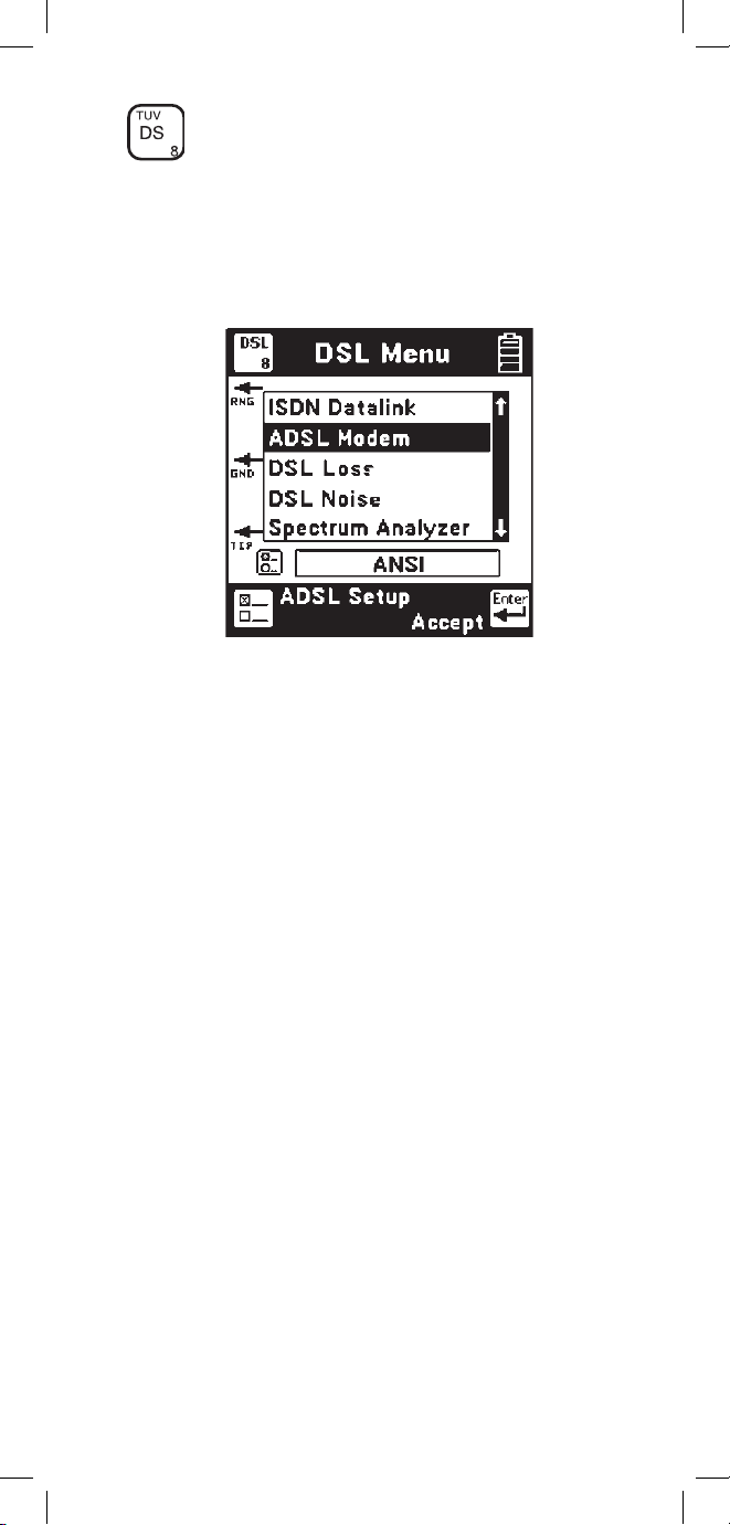
DSL
Use this function to perform specialized tests on
ISDN and DSL lines. Use the [Up] and [Down]
arrow keys to move to the desired test, then press the
[Enter] key to accept the choice.
L
Note: All 965DSP Series Loop Analyzers are
equipped with the ISDN Datalink function; however,
this menu item is suppressed in countries where
ISDN interoperability with the 965DSP has not been
verified. Units equipped with the /ADSL option will
display the ADSL modem function. Units equipped
with the /SA option will display the DSL Loss, DSL
Noise, and Spectrum Analyzer functions.
ISDN Datalink (supported countries only)
The 965DSP has an integrated 2BIQ Echo
Canceling Adaptively Equalized ISDN transceiver
which conforms to the ANSI T1.601 standard.
2B1Q ISDN is sometimes called “National
Implementation” or “NI1” ISDN in North American
countries. It is sometimes called “Euro-ISDN” in
Europe and other countries.
Note: The 965DSP will not detect older ISDN
formats (such as ATT AMI, NT AMI, etc.).
Page 72

72
Connect the red and black leads to the pair and press
the [Enter] key. The 965DSP displays the word
“Connecting” while the instrument goes through
three steps:
1) AIP (Activation in Progress),
2) Sync (Synchronization) , and
3) Link (successful connection).
If any of these three tests is unsuccessful, the words
“Link Failed” will show in the screen.
Once a link is established with an ISDN signal, the
screen will display “Connected” in the main screen.
For countries where interoperability with the 965DSP
ISDN Block Error Test has been verified, the [Enter]
key will appear. Press the [Enter] key to perform an
Error Test on the active ISDN pair.
Page 73

73
The 965DSP will count and display the number of
near-end and far-end errors.
“Near-end” errors are the errors detected at the
965DSP. “Far-end” errors are errors detected at an
ISDN line card. (The far-end count is transmitted to
the 965DSP over the ISDN link.)
The screen displays the elapsed time since the start of
the ISDN Error Test. Standard practice is to monitor
the line for a fixed period of time (for example, 5 or
15 minutes) and count the number of errors.
Near-end and far-end errors are “blocks” of bit
errors. If there are no block errors in a given period
of time, this insures there will be no bit errors in the
same period.
The 965DSP will automatically stop counting errors
after 15 minutes.
The word “Link” will be displayed as long as the
965DSP is linked to the ISDN line. If the link is lost,
the screen will display “Link Lost.”
Press the [Enter] key to start the test again.
ISDN Error Test (supported countries only)
The 965DSP can perform a near-end and far-end
block error test after linking to an active ISDN line.
.
Note: This function is suppressed in countries
where ISDN interoperability with the 965DSP
Block Error Test has not been verified.
Page 74

74
ADSL Modem (/ADSL option only)
965DSP models which include the ADSL modem
function are identified by the /ADSL option on
their Welcome screens. The Welcome screens for
the 965DSP/ADSL and 965DSP/SA/ADSL are
shown below.
Use the ADSL modem feature to establish a link
with a DSL Access Multiplexer (DSLAM) in the
central office or remote cabinet and determine the
ADSL data rate that the pair will support.
The internal ADSL modem in the 965DSP
complies with international standards such as
G.DMT (ITU G.992.1 Annex A), G.Lite (ITU
G.992.2), and ANSI T1.413 II. It will connect with
DSLAM’s that are similarly compliant.
Connect the red and black leads to the pair.
The ADSL modem in the 965DSP is used as
the customer premises equipment (CPE). Data
directions are referenced as Upstream and
Downstream. Downstream is the direction from the
DSLAM to the CPE (965DSP). Upstream is the
direction from the 965DSP back to the DSLAM.
Press the ADSL Setup key to select the type of
ADSL connection and Pass/Fail thresholds or else
press the [Enter] key to connect.
Page 75

75
ADSL Setup
Use ADSL setup to select the desired test type,
ADSL service type, and to enable or disable Pass/Fail
thresholds. Use the [Tab] key to move between fields
and the [Up]/[Down] arrows to select an option.
Select Captured Test to set up a link, measure the
line performance, and drop the line automatically to
save battery life. The data screens in Captured Test
mode are ‘snapshots’ of the line performance when
the connection completes.
Select Continuous Test to stay on the line for up
to ten minutes to see if any problems start after
the line has been up for awhile. In Continuous
Test mode the screens are all ‘live’ and display
continuously updated data.
Select the desired ADSL Service: G.DMT (full
rate), G.Lite (splitterless), ANSI (frequency division
multiplexing mode), or Multimode (automatically
selects the same mode as the DSLAM).
Select Threshold On or Off to enable or disable
automatic Pass/Fail thresholds in Captured Test
mode only. Use the Thresholds key to edit the
threshold levels.
Press the Selftest key to run a diagnostic test on the
ADSL modem in the 965DSP.
Threshold Setup
Use this feature to set the acceptable data rate and
capacity factor for the ADSL service grade that
you are providing. The ADSL connect rate in each
direction has to meet or exceed the value in the
corresponding Rate field to pass. Enter the
Page 76
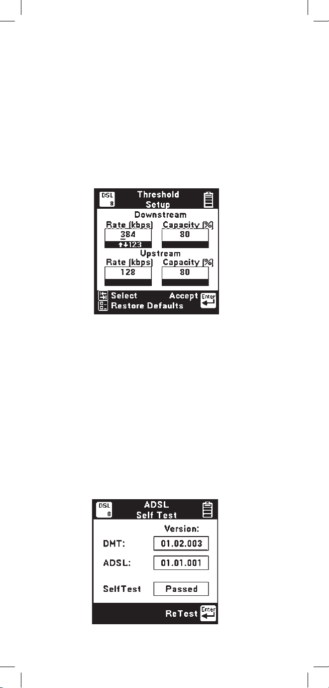
76
minimum acceptable data rate for the service grade
in the Rate field. Capacity is the ratio of the actual
connect rate to the maximum rate that the line can
support. Larger capacity values indicate less noise
margin and lower tolerance for line disturbances. This
parameter can be used to guarantee some reserve
performance capability. The line capacity in each
direction has to be less than or equal to the value in
the corresponding Capacity field to pass. Enter the
maximum acceptable capacity in the Capacity field.
Use the [TAB] key to move between fields and the
numeric keypad to enter values. Use the Restore
Defaults key to restore the Factory default values.
ADSL Self Test
Use this feature to run a self test on the internal
ADSL modem in the 965DSP. No external
connections are required. The result of the self
test and the version number of the internal modem
software are displayed. Press the ReTest key to
repeat the self test.The internal ADSL modem may
still function if the self test fails, but performance
could be degraded. Contact 3M Technical Service
for assistance.
Page 77

77
ADSL Connecting
The 965DSP displays this screen while it is
connecting with the DSLAM.
Status messages about the connection process are
displayed as they occur.
The hourglass indicator at the bottom of the screen
is displayed as the connection process proceeds.
Connection states include:
Starting: The ADSL modem in the 965DSP is
initializing
Searching: The ADSL modem in the 965DSP is
attempting to locate the DSLAM
Linking: A DSLAM is present, and the
965DSP is synchronizing with it
Connected: The 965DSP has completed the
connection process and has achieved
‘showtime’
Failed: The modem connection process failed
When the modems have connected, the 965DSP
proceeds directly to a connection status screen.
If a connection failure occurs, a warning screen
displaying a text or numeric message indicating the
failure mode is displayed.
ADSL Pass/Fail
When the connection process is complete, the
965DSP displays the Pass/Fail screen
only if
Thresholds are enabled (see ADSL Setup).
Page 78

78
Otherwise, the Status screen below is displayed.
Only the achieved Upstream and Downstream
line rates and capacity values are shown. The pair
PASSED if the line rates were greater than or equal
to the threshold rates and the capacity values were
less than or equal to the threshold capacities.
Press Status key to display more ADSL modem
connection information.
ADSL Status
The 965DSP displays all of the available information
about the ADSL modem connection on three
separate screens. The Status screen displays the
line and channel operational data. ADSL data can
be carried on a fast channel (maximum speed, but
no data correction) and an interleaved channel
(lower speed, but more data integrity). Although
both channels can exist on the same connection, in
practice only one is used. The type of channel is
selected by the DSLAM. The 965DSP displays the
data rate of this channel as well as other performance
data for both data directions as indicated below.
Page 79

79
Note: This screen is continuously updated in
Continuous Test Mode.
FAST: Achieved line rate in kilobits per second
on the Fast channel.
INTR: Achieved line rate in kilobits per second
on the Interleaved channel.
Note: FAST or INTR will display with the achieved
line rate to indicate the selected channel type.
MAX: Maximum possible attainable line rate in
kilobits per second.
MRGN: Noise margin in dB above the minimum
Signal to Noise Ratio (SNR) required
to maintain the data rate (as set by the
DSLAM).
ATTEN: ADSL signal attenuation in dB at each
end of the line.
PWR: ADSL total output power in dBm at each
end of the line.
CAP: Line capacity percentage comparing the
achieved data rate to the maximum data
rate the line will support.
Press the Info key to display more ADSL modem
connection information. If Thresholds are enabled,
use the Pass Fail arrow to return to the previous
screen.
ADSL Info
This screen displays channel performance data
as well as the DSLAM modem manufacturer
information (if available).
Note: This screen is continuously updated in
Continuous Test Mode.
Page 80

80
DSLAM modem manufacturer information is
displayed if available, but this feature is not
supported by all service types or manufacturers.
The 965DSP displays ‘unknown’ in this field if the
DSLAM manufacturer information is unavailable.
FEC, CRC, and HEC counts in each direction are
also displayed. FEC is the number of Forward
Error Correction events in each direction. These
are automatically corrected errors, and as such they
do not require re-transmission of data. CRC is the
number of Cyclic Redundancy Check errors detected
in each direction. These numeric checks indicate that
the ADSL data frame had one or more uncorrected
errors, so the data must be re-transmitted reducing
throughput. HEC is the number of Asynchronous
Transfer Mode (ATM) cell Header Error Correction
events detected in each direction. ADSL normally
carries data in ATM format to remain synchronous
with data on the network. For the modem in the
965DSP, dummy 53-byte ATM data cells are inserted
to maintain proper timing with the DSLAM. The cell
header field integrity is checked separately since it
directs the data cell to its destination, and errors in
the header can cause the loss of an entire data cell.
Press the Alarms key to display more ADSL
modem connection information or the Status key to
return to the previous screen.
ADSL Alarms
This screen displays any detected ADSL link
alarm conditions. If a link alarm occurs at any time
during the connection, the link alarm history is set
to ‘Yes’ and remains in that state for the duration of
the connection.
Page 81

81
Note: This screen is continuously updated in
Continuous Test Mode.
LOS indicates a Loss of Signal alarm. This means
that the ADSL received pilot tone power was 6dB
or more below its reference power. Pilot tones do
not carry data and are used for line synchronization.
LOF indicates a Loss of Frame alarm. Loss of
Frame occurs when the expected ADSL framing
bit sequence is not detected indicating a loss of
synchronization.
LCD FAST indicates an ATM Loss of Cell
Delineation in the Fast mode. Cell boundaries must
be maintained for proper ATM synchronization, and
this alarm indicates that the cell beginning and end
location have been lost.
LCD INTR indicates an ATM Loss of Cell
Delineation in the Interleaved mode.
LOM indicates a Loss of Margin. This means that
the measured signal-to-noise-ratio (SNR) was
below the required SNR as set by the DSLAM.
Use the Graph key to display more ADSL modem
connection information or Info to return to the
previous screen.
ADSL Graph
Note: This screen is continuously updated in
Continuous Test Mode.
Page 82

82
The ADSL Graph presents a graphic display of the
number of bits transmitted in each ADSL Discrete
Multi Tone (DMT) frequency bin. ADSL modems
require wide bandwidth to operate since they
essentially use 256 separate simultaneous modems,
each requiring about 4kHz of bandwidth called a
bin. Each of these mini-modems transmits complex
symbols (‘baud’) at 4000 symbols per second. Each
symbol represents from 0 to 15 encoded bits of
information. The number of encoded bits in each
symbol depends on the SNR of the modem bin.
A significant decrease in the number of bits per
bin can result from ADSL signal attenuation or
increased noise.
Examining the bits per bin can indicate the presence
of interfering signals in certain frequency bands of
the ADSL spectrum. To identify the bin number, bin
center frequency, and bits per bin, use the [LEFT]
and [RIGHT] arrow keys to position the cursor
on the graph. The upper left box displays the bin
number (1 – 256) at the cursor position. The upper
right box displays the number of encoded bits (0
– 15) transmitted in the selected bin. The lower box
displays the bin center frequency in kilohertz.
ADSL Results Save
You can save all of the results of an ADSL Modem
test for later upload to a computer (see ‘ADSL
Results’). After an ADSL test has completed, press
the [Save] key (camera icon) to save the results.
The 965DSP will display the Save Results screen as
follows:
Page 83

83
The date and the time display the 965DSP “system
clock.” See the “Set Clock” section on page 12 for
further information on setting the clock, and also for
information on the format of the date and time.
Use the blue keys to enter an alphanumeric ID. The ID
may have up to fourteen characters. Because there are
not enough keys for all twenty-six letters, each of the
number keys (except “1”) also function as letter keys
for ID entry. Whether a number or letter is entered
depends on how many times the key is pressed. As an
example, if the Ohms key is pressed once, the number
“3” will be displayed. If the same key is pressed
twice, the letter “d” will be displayed, three times
for the letter “e” and four times for the letter “f”.
When the desired number or letter is displayed, press
any other key to insert the next number or letter.
This will cause the previously entered characters to
move to the left making room for the new character.
If the same key needs to be used multiple times in
a row (i.e. to enter the sequence ‘ABC2’), press the
[Up] arrow to insert multiple spaces to the left of the
cursor. Use the [Left] arrow to position the cursor
under the first space and enter the first character,
and then use the [Right] arrow to move the cursor
under the next space. Insert the next character and
use the [Right] cursor again to position the cursor
to the next position. Continue entering numbers or
letters in this manner until all have been entered. If
you enter more than 14 characters, the first entered
character will be discarded. To change or delete any of
the characters that have been entered, use the [Right]
or [Left] key to move the cursor under the letter to be
changed or deleted. To delete the character, press the
[Down] key. To change the character, press the key of
the new character once (for a number) or several times
(for a letter). Once the ID has been entered, press
the [Enter] key to save the current ADSL test results
unless the User Info option (see User Info Setup page
19) is enabled. If User Info is enabled, you will see
another edit screen as shown below.
Page 84

84
Edit the Tech ID and Job Number using the
same procedure described previously. Up to
14 alphanumeric characters can be entered in
each field. Use the [Tab] key to jump between
highlighted boxes. Use the [Setup] key to clear
both fields. The data entered into each field will
remain present for every saved result until explicitly
changed or cleared. In this way information that is
infrequently changed (Tech ID for instance) does
not need to be re-keyed every time. These two fields
are appended to the ADSL Results when they are
printed or stored in PCLink.
At least 40 ADSL test results can be saved. The
percentage of remaining memory for results storage
is shown in the box at the top of the screen. The
number of saved TDR or Autotest results does not
impact the number of ADSL results that can be
saved.
ADSL Warning Screens
ADSL warning screens are intended as informational
aids and provide additional explanatory data. Warning
screens can be categorized into four groups: modem
information, link activation failures, connection lost,
and timeouts.
Page 85

85
965DSP Modem Information
Conditions affecting the internal ADSL modem in
the 965DSP are displayed via warning screens.
In the unlikely case that the warning message
shown above appears, simply exit the ADSL
Modem application for a few minutes to allow the
modem to cool down.
Link Activation Messages
Error conditions affecting the ADSL modem link
activation process are displayed as ‘Connection:
Link Error’ with numeric codes and abbreviated
text definitions.
Page 86
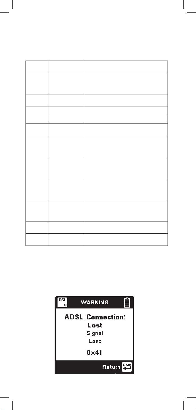
86
Connection Lost Messages
Error conditions causing modem link loss are
displayed as ‘Connection: Lost’ with numeric codes
and abbreviated text definitions.
Common error codes and their causes are listed in
the table below. Contact 3M Technical Service for
any undefined codes.
ciremuN
edoC
noitinifeD gninaeM
50x0
elbitapmocnI
snoitidnoCeniL
ontegrat,etardetseuqerfonoitanibmoC si e
oPdewolladna,nigram w lartcepSre
enilehtnoelbissoptonsiytisneD
0 7
0x tuoemittcennoC
tcennoctondidmedoM
iw sdnoces04niht
80x0 tuoemitesolC desolcylreporptonknilmedoM
A0x0 elbissoPkcoLoN MALSDehthtiwkcolotelbanU
F0x0 rorrElocotorP
noitavitcaehtgnirudderruccoeruliafA
ssecorp
41x0 rorrEegasseM
noitavitcaehtgnirudegassemdeviecerA
CRCarotamrofgnorwehtdahssecorp
rorre
91x0
UTAsuoirupS
De detcet
MALSDsadeifitnediyltcerrocniesioN
denotnoitavitca e esleroenilnodetcet
CRCerofebdevieceregassemderorre
.nagebgnissecorp
E1x0
tibdetseuqeR
rofhgihootetar
etiL.G
ehttahtsetacidnirorresiht,edometil.GnI
tsaFehtdetseuqeryltcerrocnisahMALSD
.lennahc
32x0
devaelretnI
deriuqereliforp
etiL.Grof
ehttahtsetacidnisiht,edometiL.GnI
tsaFehtdetseuqeryltcerrocnisahMALSD
.lennahc
82x0 ecnelisdecroF
gnirudedomlagellidetseuqersahMALSD
.ecneuqesnoitavitca'decrof'
D2x0
elbatcelesnU
edoMnoitarepO
noitarepofoedomnommoceveihcatonnaC
.MALSDhtiw
Page 87

87
Numeric
Code
0 x 41
0 x 50
0 x 51
0 x 53
0 x 54
Definition
Signal Lost
Frame Lost
Margin Lost
Cell Delineation
Lost
Meaning
Interruption in the path between the
modems lasting at least 2.5 seconds
Loss of ADSL framing lasting at
least 2.5 seconds
Required noise margin was lost for
at least 2.5 seconds
ATM cell delineation lost for at
least 2.5 seconds
Numeric
Code
0 x 21
0 x 22
0 x 07
0 x 08
Definition
Open Rejected
Open Failed
Connect Timeout
Close Timeout
Meaning
Illegal parameters or modem not
ready
Modem failure detected during
activation process
Modem did not connect within 40
seconds
Modem link not properly closed
Common error conditions and their causes are listed
in the table below. Contact 3M Technical Service
for any undefined codes.
Link Timeout Messages
Error conditions causing modem timeouts are displayed
as ‘Connection: Timed Out’ with numeric codes and
abbreviated text definitions.
Common error conditions and their causes are listed in
the table below. Contact 3M Technical Service for any
undefined codes.
Page 88

88
Press the [Setup] key to choose a DSL service.
Use the [Up] and [Down] keys to highlight the
desired service. Press [Enter] to select the service
and return to the previous screen.
DSL Parametric Tests (/SA option only)
965DSP models which include DSL Parametric
Tests are identified by the /SA option on their
Welcome screens. The Welcome screens for the
965DSP/SA and 965DSP/SA/ADSL are shown
below.
For DSL loss and DSL noise measurements (/SA
option only), you first need to select the type of DSL
service that you want to test. This automatically
selects the appropriate line termination impedance
and noise weighting filter for the selected service.
Parameters for the different services are indicated in
the table below.
Frequency
Service Termination Filter Range
ISDN/IDSL 135 Ω E 1kHz – 50kHz
HDSL 135 Ω F 4.9kHz – 245kHz
ADSL 100 Ω G 20kHz – 1.1MHz
Page 89

89
DSL Loss (/SA option only)
Use this function to measure loss from the far-end to
near-end using a tone between 20kHz and 1.2MHz.
You must use a separate instrument to generate the
tone at the far-end.
Press the [Tab] key to move between metallic noise
power measurement across the pair and longitudinal
noise power of the conductors to ground. The
highlighted reading is ‘live’ and continuously
updated.
The screen displays noise power (referenced to
-90dBm), selected service type, noise weighting
filter, and the metallic terminating impedance.
The screen displays the signal level in dBm, the
frequency of the tone in kHz, the selected service
type, and the line terminating impedance. Press
[Enter] to return to the DSL menu.
DSL Noise (/SA option only)
Use this function to measure wideband metallic and
longitudinal noise on a pair. Connect the red and
black test leads to the pair and green lead to ground.
Page 90

90
Spectrum Analyzer (/SA option only)
This function provides a graphic display of the
signals and noise on a line over a selected range of
frequencies. Connect the red and black test leads to
the pair. Use the [UP] and [DOWN] arrow keys to
select the frequency span of interest. The endpoints
of the frequency span bar will change to indicate
the frequency range. Use the [LEFT] and [RIGHT]
arrow keys to move the cursor across the screen. The
frequency of the cursor position appears in the center
of the span bar.
The 965DSP continuously analyzes the signals and
noise present on the pair. The screen displays the
average power of all the signals and noise in the
selected span in dBm at the upper left. The actual
signal level at the cursor position is displayed in dB
at the upper right.
Interfering noise signals on a pair often occur
as the result of crosstalk from other wideband
services in the same cable. Each wideband service
type has a unique frequency signature. Use the
spectrum analyzer to classify the source of the noise
interference on a pair.
Page 91
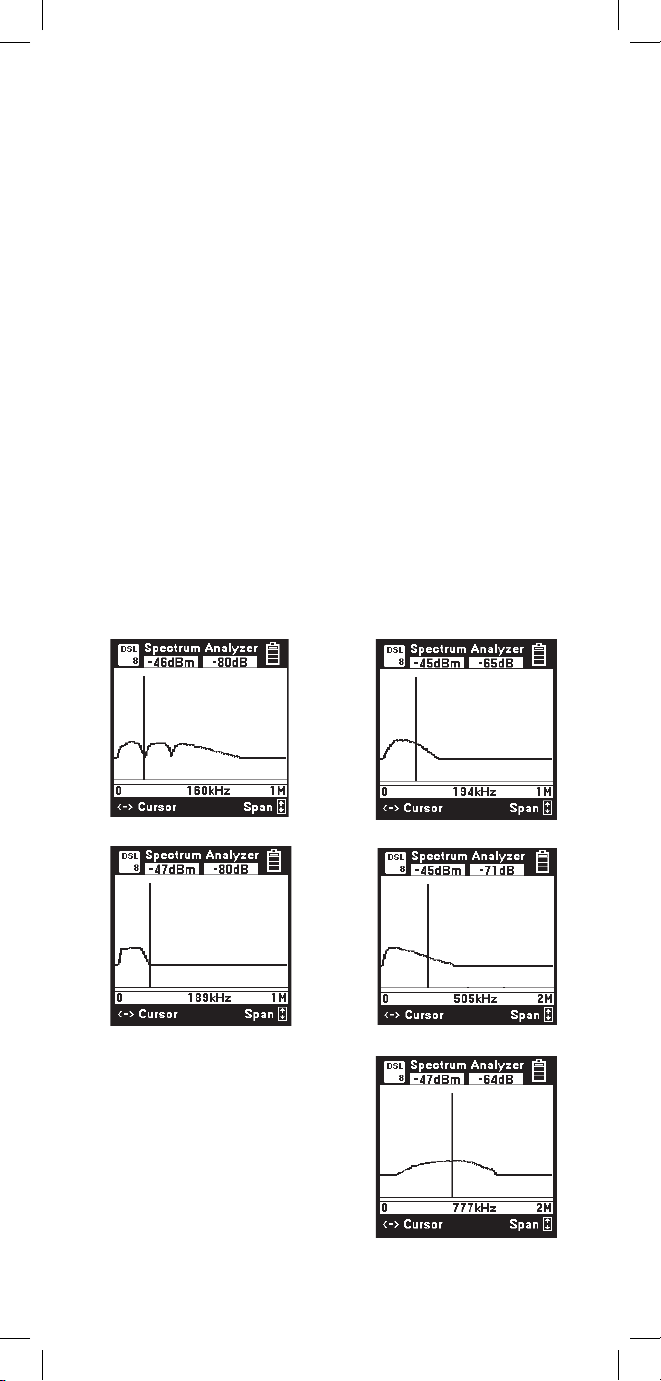
91
Interference Frequency Signatures
The 965DSP Spectrum Analyzer function provides
a graphical display of the signals and noise on a line
over a selected range of frequencies.
The spectrum analyzer continuously analyzes the
line and updates the screen as conditions change.
The screen displays the average power of all signals
and noise in the selected frequency span in dBm at
the upper left. The actual signal level at the cursor
position is displayed in dB at the upper right.
Interfering noise signals on a pair often occur as the
result of crosstalk from other wideband services in
the same cable.
Each wideband service type has a unique frequency
signature as shown in the following figures. Use
the spectrum analyzer to classify the source of
the noise interference on the pair. Following are
some examples of the most common frequency
signatures.
ISDN Interference
HDSL Interference
T1 Interference
ADSL Upstream Interference
ADSL Downstream Interference
Page 92

92
Proper Operation
The 965DSP Subscriber Loop Analyzer measures
extremely low noise levels and requires proper
handling of the test leads to ensure consistent
measurements. Extend the test leads away from the
965DSP when conducting DSL tests, and make sure
that the red and black leads are kept as close together
as possible to minimize RF noise pickup.
Note: Do not attempt to conduct DSL noise or loss
measurements while the external DC charger is
connected.
Page 93

93
TDR
This function shows the pair as a “trace” on the
screen. TDR measures distance to events based on
input about the pair.
Press the [Up] or [Down] keys to move to a desired
selection. Press the [Enter] key to accept the choice and
start the measurement.
TDR Setup
TDR features a setup function that allows you to enter
the cable type, gauge and first length. Vp is then
automatically set from these selections. Press the [Setup]
key to change the Cable Type, Gauge, or to select either
minimum first length or last used.
There are six modes to view a pair: 1) Single Trace to
view a single pair. 2) Dual Trace to view two pairs at the
same time. 3) Differential to view the difference between
two pairs. 4) Crosstalk to view the electrical coupling
between two pairs. 5) Memory to compare a “live” trace
with a trace stored in memory. 6) Peak to display a history
of maximum and minimum values with the live trace.
Page 94

94
Connect the red and black test leads to the pair under
test. Single Trace is used to view a single pair at a
time.
Dual Trace
Connect the red and black test leads to the pair under
test. Connect the blue and yellow test leads to the
reference pair.
Single Trace
Page 95

95
Use the Crosstalk mode to display the amplitude and
location of signals that “cross” from one pair to the
other, as could be caused by a split.
For both Differential and Crosstalk, connect the red
and black test leads to the pair under test. Connect
the blue and yellow test leads to the reference pair.
The pair under test is displayed at the top of the
screen. The reference pair is displayed at the bottom
of the screen. Any changes in the control parameters
affect both traces. It is not possible to control each
trace independently.
Dual Trace is used to compare two pairs at the same
time (usually a faulted and a good pair).
Differential and Crosstalk
Use the Differential mode to display only the
differences between two pairs (usually a ‘good’ pair
and a pair under test).
Page 96

96
Memory
Connect the red and black test leads to the pair under
test. Memory mode is used to compare a pair under
test to a stored trace in memory.
The first screen in memory mode will show a list of
the ID numbers for all stored TDR traces. Use the [Up]
and [Down] keys to highlight the desired stored result.
Press the [Enter] key to select the highlighted result
and display the stored results list for that ID number
by type (TDR), date, and time.
Use the [Up] and [Down] keys to highlight the
desired stored result. Press the [Enter] key to display
the stored trace on the bottom of the TDR screen and
the “live” trace on the top.
Page 97
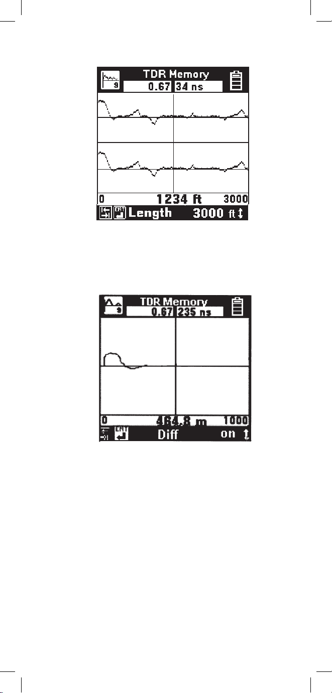
97
You may move the cursor by using the [Left] and
[Right] keys. The control settings for the stored trace
can be viewed by pressing the [Tab] or [Enter] keys
but the settings cannot be changed.
The TDR Memory function includes a Difference
control, accessible from the memory screen by
pressing the [Tab] key. The default is Diff Off. Use
the [Up] or [Down] arrow key to turn Diff on. Diff
combines the live trace with the stored trace to show
the difference in the two readings.
The TDR Memory screen defaults to the control
settings that were active when the stored trace was
saved using the “TDR Save” function.
Page 98

98
Peak
Use the TDR Peak mode to capture events that may
be intermittent. This mode continuously detects and
displays the maximum and minimum traces that
occur from the time that the mode is first selected.
The ‘live’ trace is also displayed continuously. As a
new maximum or minimum trace is detected, it will
replace the previous one on the display.
If the pair being tested is stable (no intermittent
faults), then the minimum, maximum and “live”
traces should appear as a single trace.
If any of the control values are changed, the peak
histories will be erased and new values will begin to
display.
Page 99

99
Filter: is Out, is In
Filter allows you to switch in a filter to remove noise. You
should use the filter if you see noise on the display. Note:
Switching in the filter may make it difficult to detect
small events on the cable.
Length:
100 ft, 200 ft, 500 ft, 1 kft, 2 kft, 5 kft, 10 kft, 20kft,
30 kft
(30m, 60m, 150m, 300m, 600m, 1.5 km, 3 km, 6 km,
10 km)
Length allows you to set the distance (or span) from the left
side of the screen to the right side. The left side of the screen
is usually at the test set, and the right side is the furthest
distance that can be displayed with the length selected.
Use the [Tab] and [Enter] key to move forward or
backward through the TDR controls.
Use the [Up] and [Down] key to change the parameters
for the control selected.
Individual controls and their parameters are described as
follows:
Pulse Width: 5 ns, 34 ns, 235 ns, 1600 ns
Pulse Width allows you to select the width of the pulse
sent out on the pair. The 965DSP automatically chooses the
best pulse width for each length selected. Note that you can
change the pulse width independent of length.
Use a shorter pulse width to give better resolution of events.
A shorter pulse width will not go as far on the pair.
Use a wider pulse width to see further on the pair. Note that
the resolution of a wider pulse will not be as good as a
shorter pulse.
Pulse Width is also displayed at the top right of the display.
TDR Controls
The controls described below are valid for all modes
except the Memory mode. The 965DSP displays the
controls and other parameters at the bottom of the screen.
Page 100

100
Vp (Velocity of propagation): 0.50 to 1.00
(75 to 150 m/uS)
Vp allows you to adjust the velocity factor
(“propagation velocity”) of the pair or cable.
Different cable types have different values of Vp.
To get the most accurate distance, Vp should be
set to the exact value for the cable being tested.
Vp is displayed at the top left of the screen.
Note: Vp can be displayed in m/uS (see Units
Setup on page 10 for more information).
The following is a list of approximate values for
several cable types and gauges:
Water in cable will increase the value of Vp. If the
cable has water in it, distances will appear shorter
than they actually are.
PIC:
19 AWG 0.69 (108 m/us)
22 AWG 0.68 (102 m/us)
24 AWG 0.67 (100 m/us)
26 AWG 0.66 (99 m/us)
JELLY-FILLED:
19 AWG 0.66 (102 m/us)
22 AWG 0.65 (97 m/us)
24 AWG 0.64 (96 m/us)
26 AWG 0.63 (94 m/us)
PULP:
22 AWG 0.69 (103 m/us)
24 AWG 0.68 (102 m/us)
26 AWG 0.67 (100 m/us)
Gain: 0db, 6db, 12db, 18db, 24db, 30db, 36db,
42 db, 48db, 54db through 198 db - for a
total of 34 gain settings.
Gain allows you to select the vertical gain of the
TDR. Higher gain will make events look taller on the
screen and is helpful for finding small faults. The
gain settings are selected as a db level.
 Loading...