

Page 1
3
Dynatel™
Advanced Modular System
965AMS
Version 4.01.17 User’s Guide
November 2010
78-8135-5011-4-D
Future-Proof Testing Platform
Page 2

Page 3

Contents
Introduction .....................................................................................5
Getting Started ..........................................................................................5
Welcome Screen ........................................................................................7
Help ...........................................................................................................7
High Voltage .............................................................................................8
System Setup ................................................................................... 9
Country .....................................................................................................9
Language .................................................................................................10
Module ....................................................................................................11
Network Setup ........................................................................................11
Units ........................................................................................................12
User Info .................................................................................................14
Clock Settings .........................................................................................15
Set Beep Volume .....................................................................................18
Power Down Timeout .............................................................................19
Custom Cable ..........................................................................................20
Voltage Termination ................................................................................24
Measurement Functions ................................................................ 26
Volts-DC or AC .......................................................................................27
Loop Current ...........................................................................................29
Ohms Measurements ...............................................................................32
Toolbox ...................................................................................................38
Internet Explorer .....................................................................................44
Opens ......................................................................................................48
Tone .........................................................................................................53
RFL (Resistance Fault Locate) ...............................................................58
DSL (Digital Subscriber Line) ................................................................99
TDR.......................................................................................................117
POTS .....................................................................................................137
Auto Test ...............................................................................................163
Talk Set .................................................................................................185
Care & Maintenance .................................................................... 191
3
Page 4

System Modes .......................................................................................191
AC Charger ...........................................................................................192
DC Charger ...........................................................................................192
Level of Charge .....................................................................................193
System Reset .........................................................................................193
Battery Pack ..........................................................................................194
Battery Holder .......................................................................................196
Test Leads .............................................................................................196
Self-Test Board ............................................................................197
Specifications .............................................................................. 199
Electrical Specications ........................................................................199
General Specications ..........................................................................202
Contact 3M ................................................................................... 203
4
Page 5
3M™ Dynatel™ Advanced Modular System 965AMS Introduction
Introduction
Getting Started
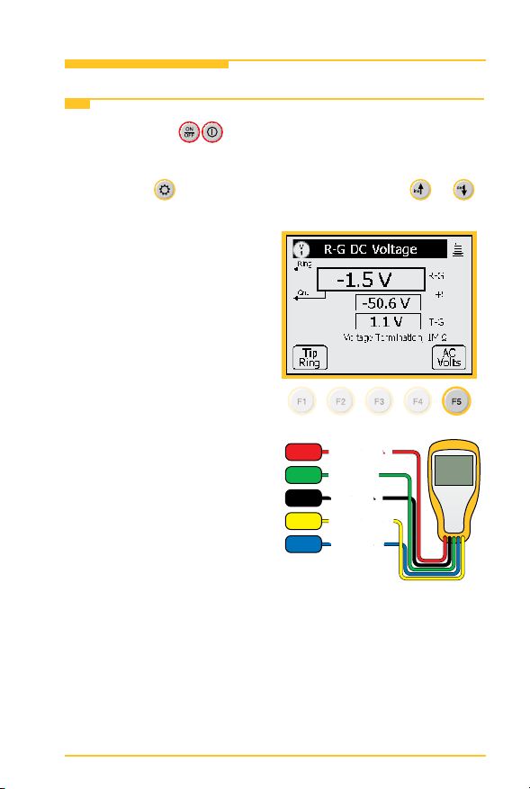
1. Press the red key to power up the unit or to power
down the unit.
2. Press the
key to change the contrast. Use the or
keys to adjust the contrast on the screen.
3. F1 through F5 are the soft
keys. Their function is
displayed in the box above
the key.
Example: To use the AC
Volts, press F5.
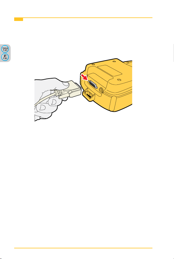
4. At the beginning of each
chapter there will be a
wiring diagram showing
the test lead hook-up. The
screen will also show the
test lead hook-up.
RED
GRN
BLK
YEL
BLU
Ring (B) 1Ring (B) 1
Ground
Ground
Tip (A) 1
Tip (A) 1
Ring (B) 2
Ring (B) 2
Tip (A) 2
Tip (A) 2
5
Page 6
Introduction 3M™ Dynatel™ Advanced Modular System 965AMS
Getting Started
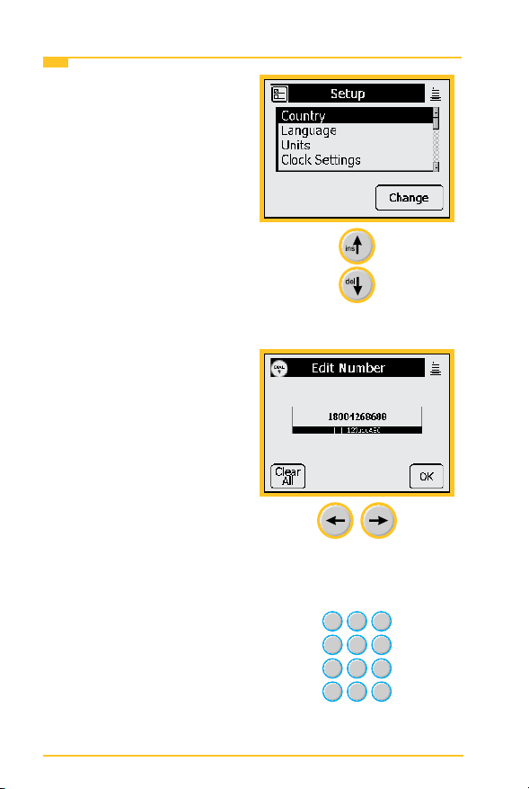
5. Some screens require you
to choose from a list of
possible choices.
Use the up and down arrow
keys to make your choice.
6. Other screens may allow
you to enter information
such as telephone numbers.
You can position the cursor
by using the Left and Right
arrow keys.
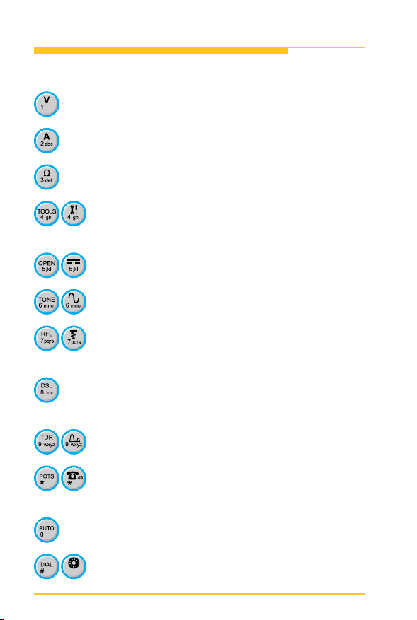
7. This symbol indicates you
should use the blue keys
to enter numeric values or
numbers.
6
Page 7
3M™ Dynatel™ Advanced Modular System 965AMS Introduction
Getting Started
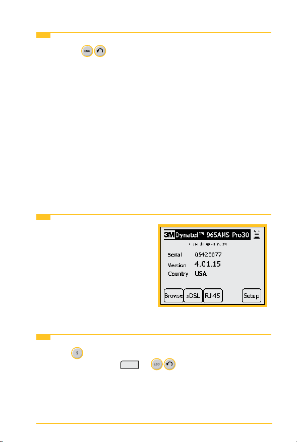
8. Use the (escape) key to quit the current screen
without making any changes. Use multiple escapes to return
to the Welcome screen.
9. The battery symbol in the upper right-hand corner of
the display gives an indication of the approximate battery
capacity. Each bar represents one-quarter of the full
capacity.
10. The unit is powered by a rechargeable NiMH battery pack.
The unit will also work with the “AA” battery pack. Six
“AA” batteries are required. Dispose of the batteries per
your company procedures. See Care & Maintenance for
more information on using the rechargeable battery pack.
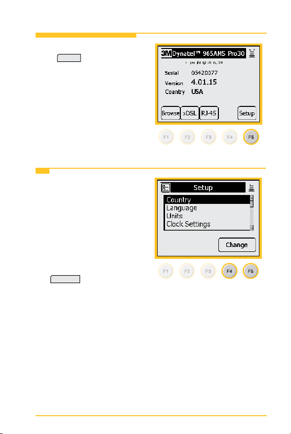
Welcome Screen
This is the screen that you see
when you rst turn on the tester.
It shows the model name, serial
number, software version, and
selected country.
Help
Press the key at any time in any screen to get help with the
current function. Press
screen.
7
OK
or to return to the previous
Page 8
Introduction 3M™ Dynatel™ Advanced Modular System 965AMS
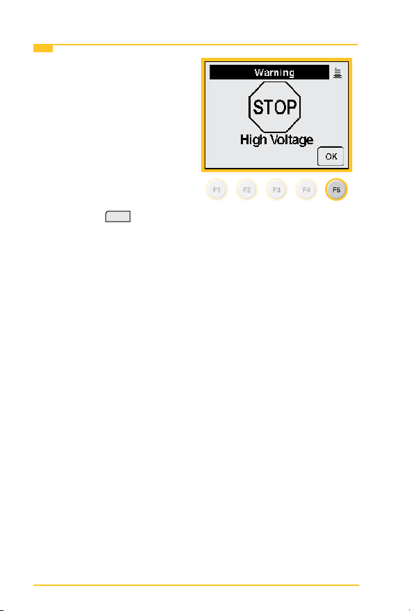
High Voltage
This screen indicates a high
voltage (120 VAC/VDC or
greater) has been detected
between the test leads when not
in the Voltage Mode. The tester
has opened an internal relay
to protect itself from damage.
Use standard safety practices
for disconnecting the test leads
since high voltage may be
present. Press
the 965AMS tester.
OK
to restart
8
Page 9
3M™ Dynatel™ Advanced Modular System 965AMS System Setup
System Setup
Start with the Welcome Screen.
Setup
Press
global settings or to make
changes.
Country
1. Use the Country setup to
congure the tester for a
specic country. Selecting a
new country will congure
the tester with the setups
for language, units, clock
format, wire gauges,
and cable types for that
particular country. Press
or to review the current
settings.
to review the
Change
to make changes
9
Page 10
System Setup 3M™ Dynatel™ Advanced Modular System 965AMS
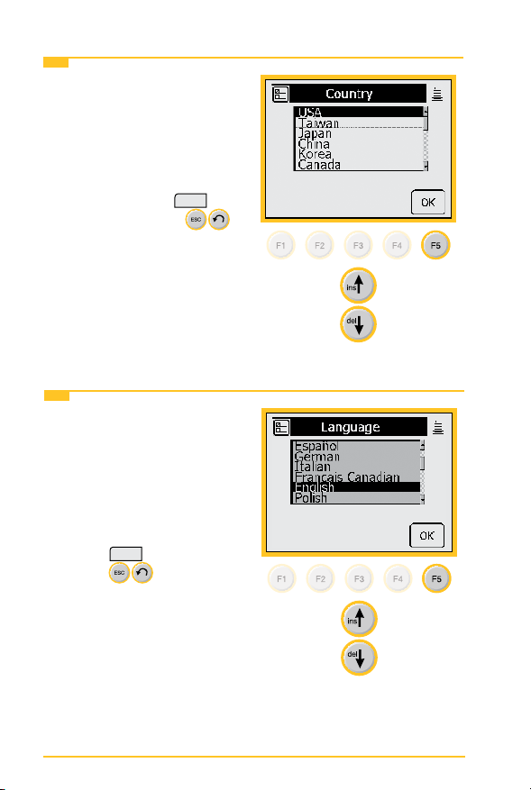
Country
2. Use the up and down arrow
keys to highlight a country.
You will be warned about
changing country-specic
default values and asked
to conrm or cancel your
selection. Press
continue or press
OK
to
to quit without making
changes.
Language
1. Use the Language setup to
change only the language
in the tester. Country-
specic default values are
not affected. Use the up
and down arrow keys to
highlight a new language.
OK
Press
press
making changes.
to continue or
to quit without
10
Page 11

3M™ Dynatel™ Advanced Modular System 965AMS System Setup
Module
1. Use the Module setup to
select the type of module
that is installed in your
tester. The module type is
listed on the label on the
module.
Use the up and down arrow
keys to highlight Module.
Change
Press
to make
changes or to review the
current settings.
Network Setup
1. Use Network Setup
to change network
options used to connect
to computers or ADSL
circuits.
Use the up and down arrow
keys to highlight Network
Setup. Press
make changes or to review
the current settings.
Change
to
11
Page 12
System Setup 3M™ Dynatel™ Advanced Modular System 965AMS
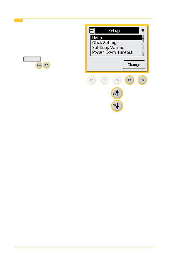
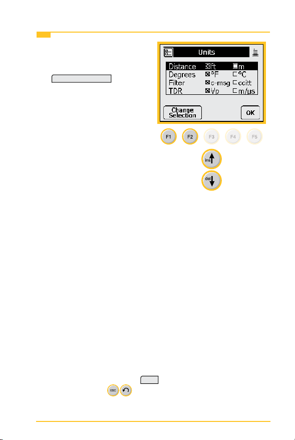
Units
1. Use the Units menu
to change the Units of
Measure. Use the up
and down arrow keys to
highlight Units. Press
Change
to continue or
press
making changes.
to quit without
12
Page 13
3M™ Dynatel™ Advanced Modular System 965AMS System Setup
Units
2. Use the up and down arrow
keys to select the units
you want to change. Press
Change Selection
the units of measure. An
“X” in a box indicates your
choice.
Distance: Feet or Meters:
This affects all distances
displayed in the 965AMS
tester.
Degrees: Fahrenheit or
Centigrade: This affects all
temperatures used in the
965AMS tester.
Filter: C-Message or CCITT: This affects the lter
used in the POTS Noise function. Use the C-Message
lter in the US and Canada. Use the CCITT (also called
“Psophometric”) lter in all other countries.
The 965AMS tester features a dBrnP lter for noise tests
in New Zealand. To set the default noise lter to dBrnP, set
Filter option to CCITT. This lter is used only in units sold
in New Zealand; for all other countries, the CCITT option
uses a dBrnOp lter. Noise test results will be displayed
as dBrnP.
to change
TDR: Vp (Velocity Propagation) or m/µS (meters
per microsecond): This affects the TDR “velocity of
propagation.” Use “Vp” in the US and Canada. Use “m/µS”
in other countries. Press
return. Use the
OK
to accept any changes and
key to return to the Welcome Screen
without making changes.
13
Page 14
System Setup 3M™ Dynatel™ Advanced Modular System 965AMS
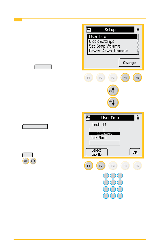
User Info
1. Select User Info to add
your Tech ID and job
number to be added to
saved test results.
Use the up and down arrow
keys to highlight User Info.
Change
Press
changes or to review the
current settings.
2. Use the blue keys to enter
your ID, name, etc. Press
Select Job ID
the Job Num eld.
Use the blue keys to enter
a job number or ID. Press
OK
to continue or press
making changes.
to make
to highlight
to quit without
14
Page 15
3M™ Dynatel™ Advanced Modular System 965AMS System Setup
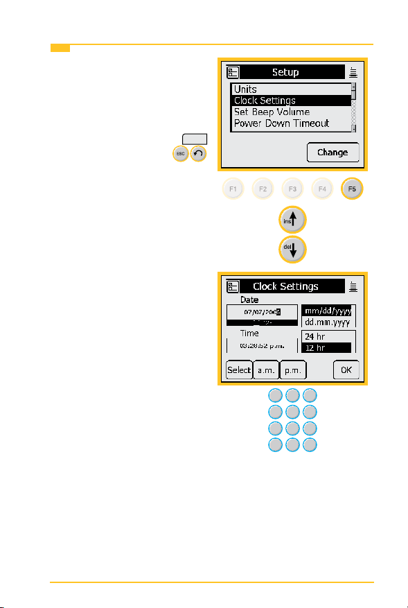
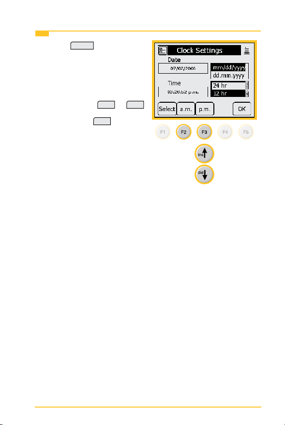
Clock Settings
1. Use the Clock Settings
menu to select the clock
format and to set the
correct time. Use the up
and down arrow keys to
highlight Units. Press
to continue or press
to quit without making
changes.
2. Use the blue keys to enter
the correct date.
OK
15
Page 16
System Setup 3M™ Dynatel™ Advanced Modular System 965AMS
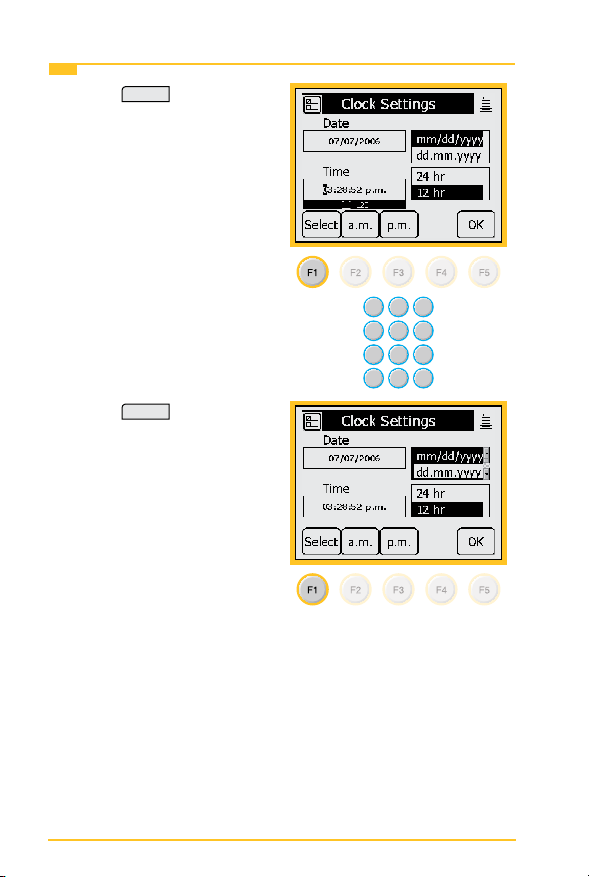
Clock Settings
3. Press
Select
, then enter the
correct time using the blue
keys.
4. Press
Select
to enter the
date format. Choose month,
day, year or day, month,
year.
16
Page 17
3M™ Dynatel™ Advanced Modular System 965AMS System Setup
Clock Settings
5. Press
Select
to choose the
12-hour or 24-hour format.
Use the up and down arrow
keys to select the format.
If you choose the 12-hour
a.m.
at
or
p.m.
format, press
Note: Press
OK
any time that you have
completed your updates.
.
17
Page 18
System Setup 3M™ Dynatel™ Advanced Modular System 965AMS
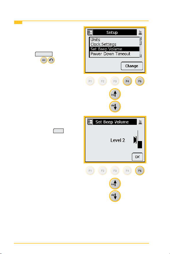
Set Beep Volume
1. Use this menu to change the
Set Beep Volume. Use the
up and down arrow keys to
highlight Set Beep Volume.
Change
Press
or press
without making changes.
2. Use the up and down arrow
keys to change the beep
volume. Press
this volume setting.
to continue
to quit
OK
to save
18
Page 19
3M™ Dynatel™ Advanced Modular System 965AMS System Setup
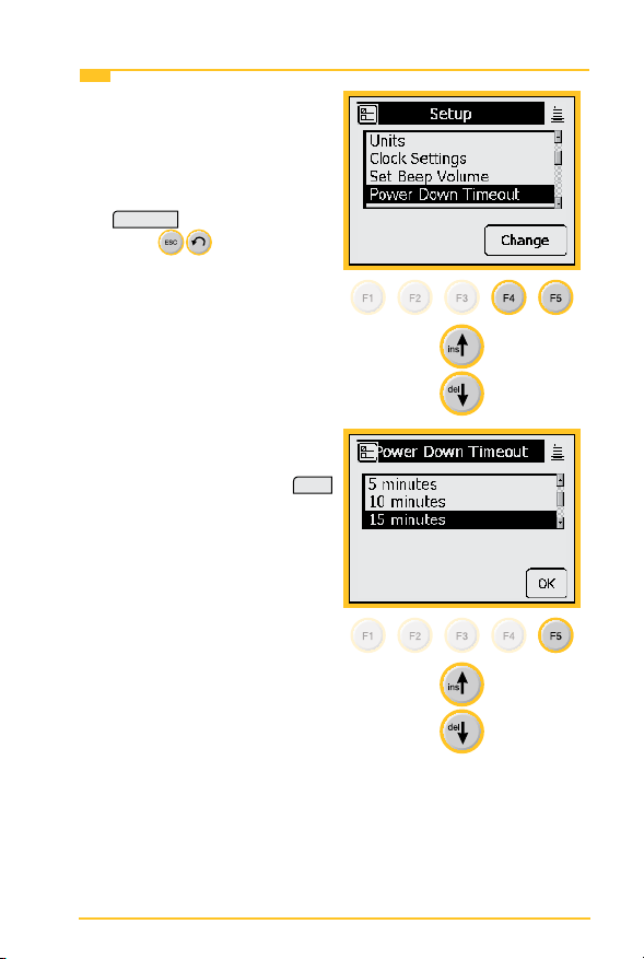
Power Down Timeout
1. Use this menu to change
the Power Down Timeout.
Use the up and down arrow
keys to highlight Power
Down Timeout. Press
Change
to continue or
press
making changes.
2. Use the up and down arrow
keys to select the timeout
you want to use. Press
to save your choice.
to quit without
OK
19
Page 20
System Setup 3M™ Dynatel™ Advanced Modular System 965AMS
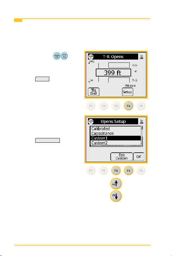
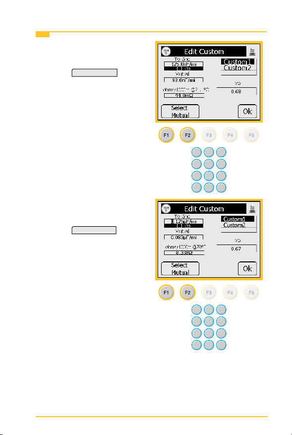
Custom Cable
Use Custom Cable 1 or Custom Cable 2 to create a special
cable you are using on a regular basis that has capacitance
values that are different from existing cables. You can also
access this function in the Opens Setup menu.
1. Press the blue
key to enter the Opens
measurement function.
2. Press
Setup
to enter the
Setup menu.
3. Use the up and down arrow
keys to select Custom 1 or
Custom 2.
Press
Edit Custom
.
20
Page 21
3M™ Dynatel™ Advanced Modular System 965AMS System Setup
Custom Cable
4. Use the blue keys to enter
the capacitance to ground.
Press
5. Use the blue keys to enter
Press
Select Mutual
.
the mutual capacitance.
Select Ohms
.
21
Page 22
System Setup 3M™ Dynatel™ Advanced Modular System 965AMS
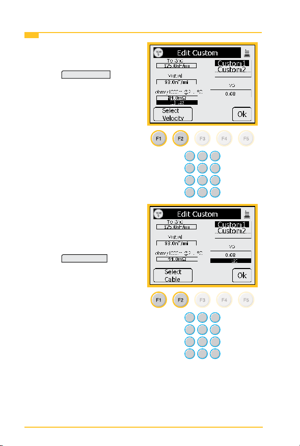
Custom Cable
6. Use the blue keys to enter
ohms per thousand feet.
Press
7. Use the blue keys to enter
Press
Select Velocity
.
the velocity propagation. If
you do not know this value,
use 0.68.
Select Cable
.
22
Page 23
3M™ Dynatel™ Advanced Modular System 965AMS System Setup
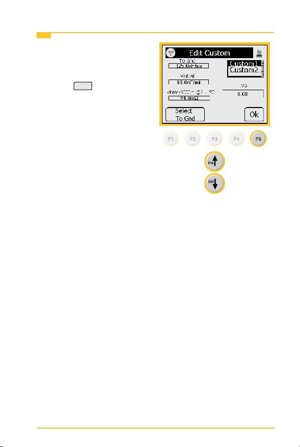
Custom Cable
8. Use the up and down arrow
keys to select Custom 1 or
Custom 2.
Press
OK
to save the
custom cable.
23
Page 24
System Setup 3M™ Dynatel™ Advanced Modular System 965AMS
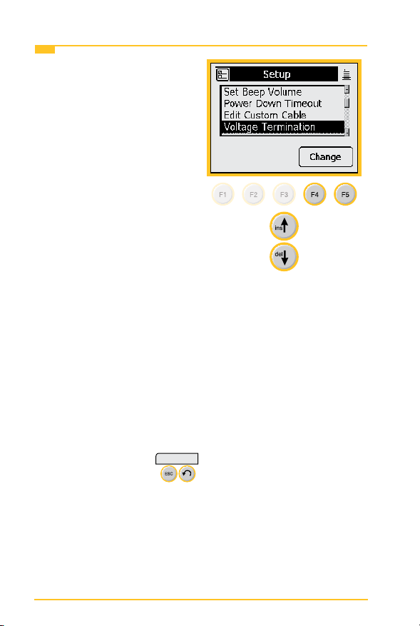
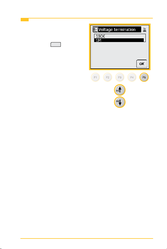
Voltage Termination
1. The Voltage Termination
option allows you to select
the input impedance of the
965AMS digital voltmeter
(in supported countries
only). The input impedance
of the internal 965AMS
voltmeter is normally
1Mohm. However, some
legacy systems use voltage
measurement systems
with input impedances of
100Kohms. This option
is provided to maintain
measurement compatibility
with those systems.
If 100Kohm termination is
selected, the 965AMS tester
will display ‘100K’ on the
voltage measurement.
Use this menu to change
the Voltage Termination.
Use the up and down arrow
keys to highlight Voltage
Termination. Press
to continue or press
to quit without making
changes.
Change
24
Page 25
3M™ Dynatel™ Advanced Modular System 965AMS System Setup
Voltage Termination
2. Use the up and down arrow
keys to select the Voltage
Termination you want to
use. Press
your choice.
OK
to save
25
Page 26
Measurement Functions 3M™ Dynatel™ Advanced Modular System 965AMS
Measurement Functions
The 12 measurement functions include:
DC and AC voltage measurements
milliAmps and ground resistance measurements
Ohms measurement and Soak Test
Self-Calibrate, Stored Results and Ohms-to-Distance
Calculator
Opens distance measurement
Send Tones
Resistance Fault Locate: Distance measurement to a
resistive fault
DSL Loss and Noise plus the Spectrum Analyzer and
Resistance Balance
Time Domain Reectrometer (TDR)
POTS Loss, Noise, Longitudenal Balance, Load Coil
Counter and Caller ID
Automatic testing of circuits using “Expert Pair Tests”
Talk Set
#
26
Page 27
3M™ Dynatel™ Advanced Modular System 965AMS Measurement Functions
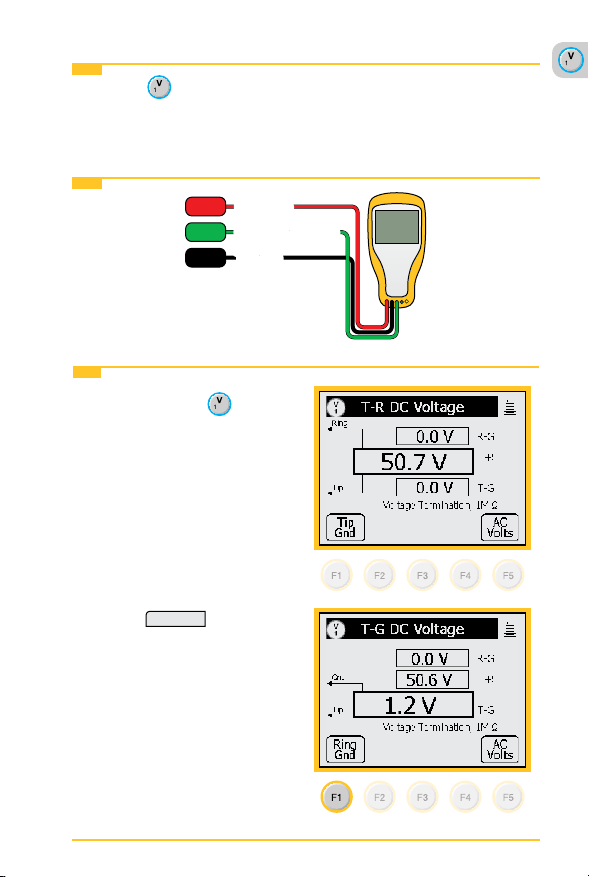
Volts-DC or AC
The Volts function measures the DC voltage or AC voltage
between Tip, Ring and Ground.
Volts-DC or AC>Hook-Up
RED
Ring (B)Ring (B)
GRN
Ground (Earth)
Ground (Earth)
BLK
Tip (A)
Tip (A)
Volts-DC or AC>Operation
1. Press the blue
key
to start the voltage
measurement function.
2. This screen displays the
T-R voltage in the larger
active measurement box.
3. Press
Tip Gnd
to display
the T-G voltage. The T-R
measurement will be
saved on the screen in a
smaller box until a new
measurement updates the
screen.
27
Page 28
Measurement Functions 3M™ Dynatel™ Advanced Modular System 965AMS
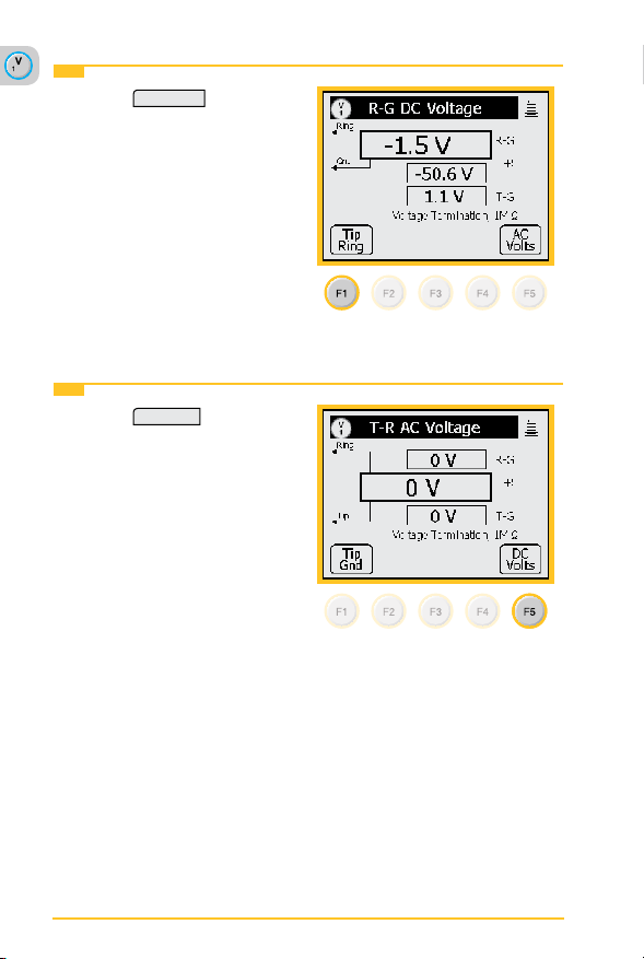
Volts-DC or AC>Operation
4. Press
Ring Gnd
to display
the R-G voltage. The
T-G measurement will be
saved on the screen in a
smaller box until a new
measurement updates the
screen.
5. All measurements are erased when you exit this function.
Volts-DC or AC>AC Volts
1. Press
AC Volts
to measure
AC volts.
AC Normal Range—Active Line:
1. R-G and T-G should have the same AC voltage. If they are
not equal the pair will probably have noise.
2. T-R should be 0 volts
Note: Maximum voltage = 300 volts DC, 250 volts AC
28
Page 29
3M™ Dynatel™ Advanced Modular System 965AMS Measurement Functions
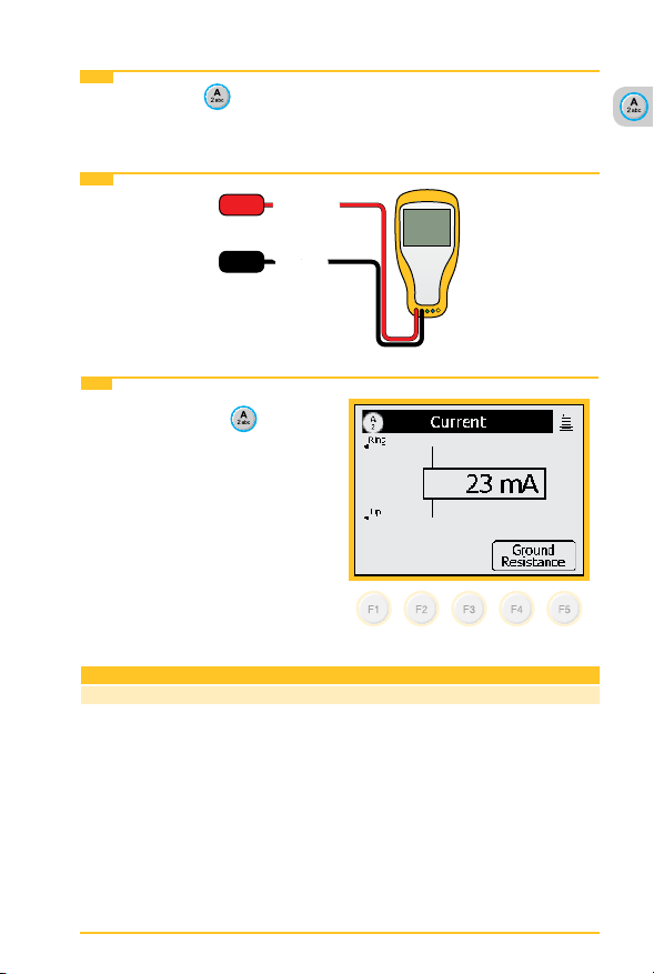
Loop Current
Loop Current measures the loop current in an active line.
Loop Current>Hook-Up
RED
Ring (A)Ring (A)
BLK
Tip (B)
Tip (B)
Loop Current>Operation
1. Press the blue
key to
start this test.
2. This is a continuous
measurement until you
disconnect the test leads or
choose another function.
Normal Measurements
Current >23mA 20-23mA <20mA
29
OK Marginal Not OK
Page 30
Measurement Functions 3M™ Dynatel™ Advanced Modular System 965AMS
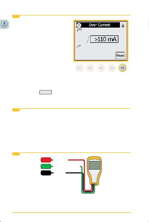
Loop Current>Operation
3. Over Current Warning
The tester has detected
a current greater than
110 mA.
Over current can damage
the test set. Use standard
safety practices for
disconnecting the test leads
and eliminating the source
of the over current.
Disconnect all test leads
then press
Retest
to
continue.
Loop Current>Ground Resistance
The Ground Resistance function compares the customer
protector ground resistance to an active central ofce pair.
Note: The Ground Resistance function only works with central
ofces with the Tip connected to ground.
Loop Current>Ground Resistance>Hook-Up
RED
Ring (B)Ring (B)
GRN
Ground (Earth)
Ground (Earth)
BLK
Tip (A)
Tip (A)
30
Page 31

3M™ Dynatel™ Advanced Modular System 965AMS Measurement Functions
Loop Current>Ground Resistance>Operation
1. Press the blue
key to
start this test.
Press
Gnd Resistance
to access the Ground
Resistance function.
2. Press
Test
to start the
test. The results will be
displayed in the box in the
center of the screen.
3. This is not a continuous
test. Press
Test
to see an
updated result.
Normal Measurements
0 Ω to 25 Ω
31
Page 32

Measurement Functions 3M™ Dynatel™ Advanced Modular System 965AMS
Ohms Measurements
The Ohms Measurement function measures the insulation
resistance between the Tip, Ring and Ground. This function
can also measure the resistance of the Tip and Ring loop or
individual wires.
Ohms Measurements>Hook-Up
RED
Ring (B)Ring (B)
GRN
Ground (Earth)
Ground (Earth)
BLK
Tip (A)
Tip (A)
Ohms Measurements>Operation
1. Press the blue
key to
start the ohms measurement
function.
2. This screen displays the
T-R resistance in the larger
active measurement box.
32
Page 33

3M™ Dynatel™ Advanced Modular System 965AMS Measurement Functions
Ohms Measurements>Operation
3. Press
Tip Gnd
to display
the Tip-Ground resistance.
The T-R measurement will
be saved on the screen in
a smaller box until a new
measurement updates the
screen.
4. Press
Ring Gnd
to display the
Ring-Ground resistance.
The T-G measurement will
be saved on the screen in
a smaller box until a new
measurement updates the
screen.
5. All measurements are erased when you exit this function.
Normal Range: POTS Insulation Resistance
Insulation Resistance >3.3 MΩ 80 kΩ to 3.3 MΩ <80 kΩ
OK Marginal Not OK
33
Page 34

Measurement Functions 3M™ Dynatel™ Advanced Modular System 965AMS
Ohms Measurements>Voltage Compensation
The Voltage Compensation
feature compensates for
crossed battery on the line.
Use “compensated” for most
measurements.
Press
V Comp
to turn voltage
compensation off and on. The
screen displays “Compensated”
or “Not Compensated.”
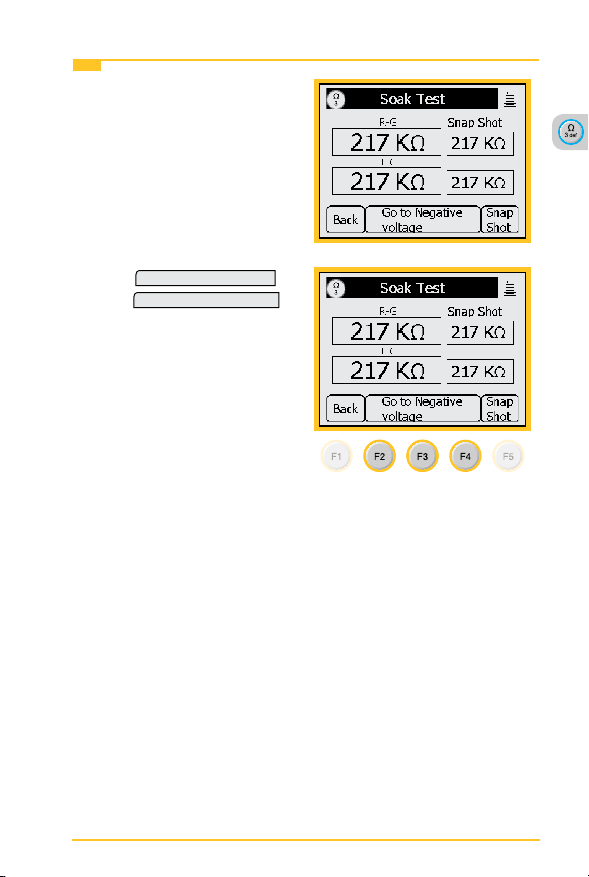
Ohms Measurements>Soak Test
The Soak Test function can
determine if the source of a
resistive fault is caused by
moisture, corrosion or pure
resistance by applying a current
to the circuit and measuring a
change in resistance.
Soak Test
Press
to access the
Soak Test menu.
NOTE: The Soak Test function
will not work properly if there
is voltage on the line. Voltage
Compensation does not apply
to the Soak Test.
34
Page 35

3M™ Dynatel™ Advanced Modular System 965AMS Measurement Functions
Ohms Measurements>Soak Test
1. Take an initial resistance
measurement by pressing
Snap Shot
the
key.
2. You will compare this to
other active measurements
to determine the source of
the fault.
3. One of the properties of
moisture in a circuit is that
the current from the tester
can “dry out” the moisture.
The display will rst show
a lower resistance, then
after one or two minutes the
resistance will increase to a
higher reading.
Initial Reading
This indicates the fault is
caused by moisture.
Note: This is not an
acceptable procedure to
“dry” a fault.
Reading After 1 or 2 Minutes
35
Page 36

Measurement Functions 3M™ Dynatel™ Advanced Modular System 965AMS
Ohms Measurements>Soak Test
4. A property of corrosion
is that a current owing
through the corrosion will
cause the corrosion to
become a better conductor.
The display will show a
lower resistance reading if
corrosion is the cause.
Initial Reading
Reading After 1 or 2 Minutes
36
Page 37
3M™ Dynatel™ Advanced Modular System 965AMS Measurement Functions
Ohms Measurements>Soak Test
5. If the resistance value does
not change, the fault is a
pure resistive fault.
and
Go To Positive Voltage
Go To Negative Voltage
to
6. Use
reverse the voltage polarity.
Use the lowest resistance
reading of the two numbers
for your measurements.
37
Page 38

Measurement Functions 3M™ Dynatel™ Advanced Modular System 965AMS
Toolbox
Use the Toolbox to: (1) view saved test results,
(2) perform a self calibrate, (3) use the Ohms to Distance
calculator, (4) use Internet Explorer and (5) Upload results to the
965AMS Results Manager.
Toolbox>Stored Results
The Stored Results function allows you to review the results of
previously saved tests.
Toolbox>Stored Results>Operation
1. Press the blue
key to
enter the Toolbox function.
Use the up and down arrow
keys to select the Stored
Results function. Press
OK
to save your choice.
38
Page 39

3M™ Dynatel™ Advanced Modular System 965AMS Measurement Functions
Toolbox>Stored Results>Operation
2. If one or more test results
have been stored, the ID
number for each will be
displayed.
The ID number is like a le
folder and each test result
is like a le. The name of
the le is the time and date
stamp that is generated by
the tester.
Press
View
to see the list
of les.
3. This screen shows the
contents of the le.
Press
Delete Result
to
delete one le or press
Delete Folder
to delete all
les in the folder.
39
Page 40

Measurement Functions 3M™ Dynatel™ Advanced Modular System 965AMS
Toolbox>Self-Calibrate
The Self-Calibrate function will verify that all of the internal
circuits and test leads are operating properly. Use self-calibrate:
• After the rst full battery charge before you put the tester in
service for the rst time.
• Anytime the working temperature changes by more than
35°F (20°C). Calibrate the 965AMS tester at the same
temperature at which it will be used.
• After changing the batteries, or anytime the battery pack
completely discharges.
Toolbox>Self-Calibrate>Hook-Up
RED
GRN
BLK
YEL
BLU
All five leads are shorted together.
40
Page 41

3M™ Dynatel™ Advanced Modular System 965AMS Measurement Functions
Toolbox>Self-Calibrate>Operation
1. Press the blue
key to
enter the Toolbox function.
2. Use the up and down arrow
keys to select the SelfCalibrate function. Press
OK
to save your choice.
3. The calibration may take up
to 1 minute to complete.
41
Page 42

Measurement Functions 3M™ Dynatel™ Advanced Modular System 965AMS
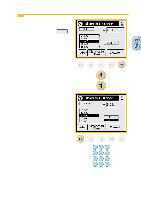
Toolbox>Ohms-to-Distance Calculator
Use this function to convert from Ohms to Distance or Distance
to Ohms based on temperature and wire gauge.
Toolbox>Ohms-to-Distance Calculator>Operation
1. Press the blue
key to
enter the Toolbox function.
2. Use the up and down arrow
keys to select the Ohms-toDistance Calculator. Press
OK
to save your choice.
3. Use the blue keys to enter
the Ohms value. Press
Select
to save and highlight
the wire gauge selection.
42
Page 43
3M™ Dynatel™ Advanced Modular System 965AMS Measurement Functions
Toolbox>Ohms-to-Distance Calculator>Operation
4. Use the up and down
arrow keys to select the
wire gauge. Press
Select
to save and highlight the
temperature eld.
5. Use the blue keys to enter
the temperature.
43
Page 44

Measurement Functions 3M™ Dynatel™ Advanced Modular System 965AMS
Toolbox>Ohms-to-Distance Calculator>Operation
6. Press
Convert
to nd the
distance.
7. Select
Distance to Ohms
if you want to convert a
distance to an Ohms value.
Internet Explorer
1. Internet Explorer is
available on the VDSL2
module.
2. Use the up and down arrow
keys to select Internet
Explorer. Press
save your choice.
OK
to
44
Page 45

3M™ Dynatel™ Advanced Modular System 965AMS Measurement Functions
Toolbox>965AMS Results Manager
The 965AMS tester uses the 965AMS Results Manager to
upload and convert les from the tester. The following les are
supported by the 965AMS Results Manager:
• Single Trace TDR
• Active POTS Autotests
• Vacant POTS Autotests
• Wideband Autotests
• xDSL Link Metrics
• xDSL Bin Graphs
Note: Only results listed above will be converted using the
965AMS Results Manager.
Toolbox>965AMS Results Manager>Software Installation
Visit www.3m.com/dynatel to nd the latest 965AMS Results
Manager.
You will need to install the following software before using the
Results Manager:
1. The following Microsoft software:
a. DotNetFX 2.0 or higher
b. Activesync 4.2 or higher
Note: Visit www.microsoft.com and search for each le
download.
2. The following 3M software will be needed.
a. 3M_Usb_Driver
b. 965AMS Results Manager
Note: Visit www.3m.com/dynatel to download the les.
45
Page 46
Measurement Functions 3M™ Dynatel™ Advanced Modular System 965AMS
Toolbox>965AMS Results Manager>Connections
1. Turn on the 965AMS tester and allow the unit to boot up.
2. Connect the 965AMS tester to power.
3. Connect the 965AMS tester to the PC via the USB to 15-pin
cable.
Note: If the “Welcome to Found New Hardware Wizard”
window appears then select “No, not this time” when asked
about connecting to Windows Update.
4. Select “No” when prompted to Set Up a Partnership.
46
Page 47

3M™ Dynatel™ Advanced Modular System 965AMS Measurement Functions
Toolbox>965AMS Results Manager>Copying Files
To copy les that are saved in a 3M Dynatel 965AMS:
1. Click on the le labelled 965AMS_Results_Manager.exe.
2. Press the Copy All XML_Results Files From 965AMS
to PC.
3. You can also delete all the les on the PC.
Note: Wait until you have veried that you are nished with
the les before deleting.
4. After you have selected a directory to save the les you
will see a progress bar and a notication of completion
when nished.
Toolbox>965AMS Results Manager>Converting Upgraded Files
To convert your saved les to HTML:
1. Start the 965AMS Results Manager.
2. Click on the tab labeled “Files on PC.”
3. Press the “Convert XML Results Files on PC to HTML for
viewing.”
47
Page 48

Measurement Functions 3M™ Dynatel™ Advanced Modular System 965AMS
Opens
Opens measures the distance to an “open” circuit. This
could be a broken wire, a cut pair or the end of the circuit.
Opens>Hook Up
RED
Ring (B)Ring (B)
GRN
Ground (Earth)
Ground (Earth)
BLK
Tip (A)
Tip (A)
Opens>Operation
1. Press the blue
key to enter the Opens
measurement function.
2. Press
Setup
Setup menu.
48
to enter the
Page 49

3M™ Dynatel™ Advanced Modular System 965AMS Measurement Functions
Opens>Operation
3. Use the up and down arrow
keys to choose the type of
cable that best describes
your cable. Press
OK
to
save your choice.
4. This screen displays the
T-R distance in the larger
active measurement box.
Press
Tip Gnd
to display
the T-G distance.
5. The T-R measurement will
be saved on the screen in
a smaller box until a new
measurement updates the
screen.
Press
Ring Gnd
to display
the R-G distance.
49
Page 50

Measurement Functions 3M™ Dynatel™ Advanced Modular System 965AMS
Opens>Operation
6. The T-G measurement will
be saved on the screen in
a smaller box until a new
measurement updates the
screen.
7. All measurements are erased when you exit this function.
Normal Range: A good pair should have the T-G and R-G
within about 2% of each other. If they are not within 2%, the
shortest distance will be the location of the fault and the other
distances will not provide accurate distances. Typically this will
be an open ground bond or a broken Tip or Ring.
Note: “Opens” is more accurate if other cable pairs are active.
If other pairs are not active, short at least 30% of the inactive
pairs to the cable shield.
50
Page 51

3M™ Dynatel™ Advanced Modular System 965AMS Measurement Functions
Opens>Calibrate Cable
Use this function to measure the capacitance of a known good
pair within a cable of known length. This value can be used as
a ‘Calibrated Cable’(or ‘reference’) to nd the distance to an
‘open’ on the same or similar cable.
1. Press
2. Press
Setup
.
Calibrate Cable
.
51
Page 52

Measurement Functions 3M™ Dynatel™ Advanced Modular System 965AMS
Opens>Calibrate Cable
3. Use the blue keys to enter
the known distance.
Measure
Press
.
4. The screen will display the
measured capacitance per
distance for the reference
pair.
52
Page 53

3M™ Dynatel™ Advanced Modular System 965AMS Measurement Functions
Tone
Use Tone to send a tone on a pair.
Tone>Set-Up
RED
Ring (B)Ring (B)
GRN
Ground (Earth)
Ground (Earth)
BLK
Tip (A)
Tip (A)
Tone>Operation
1. Press the blue
key to
enter the Tone function.
2. Use the up and down
arrow keys to highlight the
frequency that you want to
use.
53
Page 54

Measurement Functions 3M™ Dynatel™ Advanced Modular System 965AMS
Tone>Operation
3. Press
tone.
4. Press
tone.
Send Tone
Stop Tone
to send the
to stop the
54
Page 55

3M™ Dynatel™ Advanced Modular System 965AMS Measurement Functions
Tone>Edit The Frequency Of A Tone
There are 10 frequencies that can be stored in memory. If you
need a different frequency you can edit any of the displayed
frequencies and change to a new frequency.
1. Use the up and down arrow
keys to select one of the
frequencies to change.
2. Press Setup to adjust the
highlighted selection with
the following frequency
range:
ID - 200 Hz and 1,000 Hz
Precision - 200 Hz and
19,999 Hz
Wideband (965AMS Pro
tester 2) - 20 kHz and 2200
kHz.
(965AMS Pro 30 tester) -
20 kHz and 30 MHz.
3. For this example we will
replace 196 kHz with
138 kHz. Use the up and
down arrow keys to select
Wideband Tone.
55
Page 56

Measurement Functions 3M™ Dynatel™ Advanced Modular System 965AMS
Tone>Edit The Frequency Of A Tone
4. Use the blue keys to enter
the frequency in kHz.
OK
5. Press
.
Tone>Applications
The Tone function can be used for three applications: ID Tone,
Precision Tone and Wideband Tone.
Tone>Applications>ID Tone
1. Use the ID Tone for pair identication and tone coiling.
2. The ID tone is always an interrupted tone.
3. The frequency is adjustable between 200 Hz and 1,000 Hz.
4. The 965AMS tester automatically goes off-hook when an ID
tone is sent.
5. The volume control on the 965AMS tester controls the
volume you hear, but the output to the far end is set at a
xed level.
56
Page 57

3M™ Dynatel™ Advanced Modular System 965AMS Measurement Functions
Tone>Applications>Precision Tone
1. Use the Precision Tone to send a tone.
2. Use another 965AMS tester to receive the tone. Press the
blue key, then select
Loss
.
3. The output frequency of the Precision tone is adjustable
between 200Hz and 19,999Hz.
4. The output level range is –20dBm to +1dBm.
5. The most common frequencies for POTS lines are 404Hz,
1004Hz and 2804Hz.
6. The impedance is xed at 600Ω.
7. Press
8. Press
Send Tone
Stop Tone
to send the Precision tone.
to stop the Precision tone.
Tone>Application>Wideband Tone
1. Use the Wideband Tone to send a tone to the other end of a
wideband circuit to measure the signal loss.
2. Use another 965AMS tester to receive the tone.
3. Press the blue
key, then select
DSL Loss
.
4. The output frequency of the Wideband tone is adjustable
between 20kHz and 2200kHz.
5. The output level is xed at 0dBm.
6. The impedance can be set to 100Ω or 135Ω.
7. Press
8. Press
57
Send Tone
Stop Tone
to send the wideband tone.
to stop the wideband tone.
Page 58

Measurement Functions 3M™ Dynatel™ Advanced Modular System 965AMS
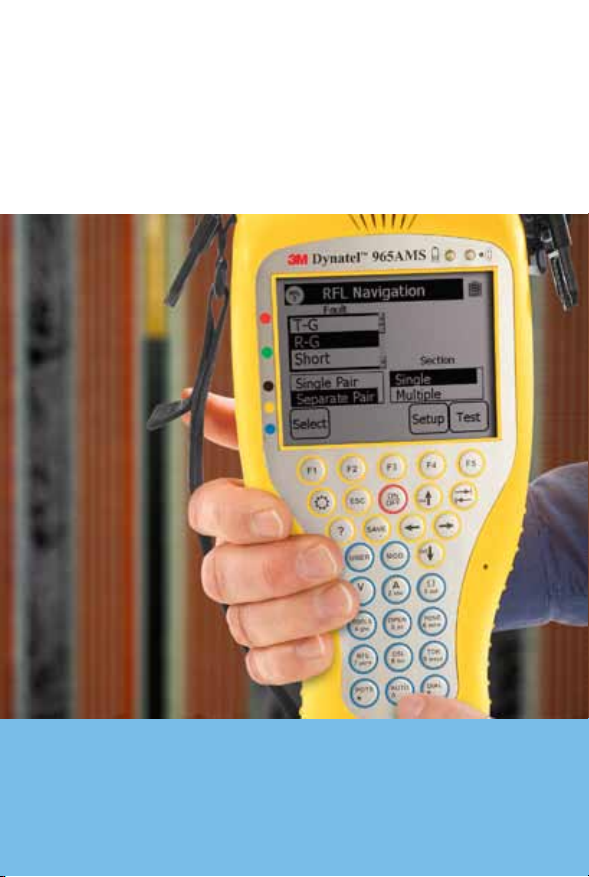
RFL (Resistance Fault Locate)
Use RFL to nd the distance to a short or ground.
Important Note: You must rst use the Auto test
Ohmmeter
, to determine the type of fault.
1. There are two types of hook-ups, Separate Pair and Single
Pair. Separate Pair is more accurate, but it requires hooking
up more wires. The “Good” wires can be any gauge and any
length. As an example, the Good wires can be jumper wire.
Separate Pair is recommended for applications where you
have a short or ground in an aerial cable or a direct buried
cable and you want to nd the fault the rst measurement.
2. Single Pair requires that the “Good” wire is the same gauge
and length as the faulted wire. Single Pair is appropriate for
situations where you are looking for the fault to be in the
nearest pedestal.
3. RFL has the ability to nd the distance to a short or ground
using a single section of cable or a section with multiple
gauges. Select Single- or Multi-section for your situation.
RFL>Hook-Up
There are ten possible scenarios for connecting a 965AMS tester
to use the RFL function:
Tip-Ground Separate Pair
, or the
GRN
Ground (Earth)Ground (Earth)
BLK
Tip (A) 1/Fault
Tip (A) 1/Fault
YEL
Ring (B) 2/Good
Ring (B) 2/Good
BLU
Tip (A) 2/Good
Tip (A) 2/Good
58
Fault
Strap
Page 59

3M™ Dynatel™ Advanced Modular System 965AMS Measurement Functions
BLK
Tip (A) 1/FaultTip (A) 1/Fault
GRN
YEL
BLU
Strap
Ground (Earth)Ground (Earth)
Ring (B) 2/Good
Ring (B) 2/Good
Tip (A) 2/Good
Tip (A) 2/Good
Fault
RFL>Hook-Up
Ring-Ground Separate Pair
RED
GRN
YEL
BLU
Short Separate Pair
RED
BLK
YEL
BLU
Tip-Cross Separate Pair
Ring (B) 1/FaultRing (B) 1/Fault
Ground (Earth)
Ground (Earth)
Ring (B) 2/Good
Ring (B) 2/Good
Tip (A) 2/Good
Tip (A) 2/Good
Ring (B) 1/FaultRing (B) 1/Fault
Tip (A) 1/Fault
Tip (A) 1/Fault
Ring (B) 2/Good
Ring (B) 2/Good
Tip (A) 2/Good
Tip (A) 2/Good
Fault
Fault
Strap
Strap
59
Page 60

Measurement Functions 3M™ Dynatel™ Advanced Modular System 965AMS
RFL>Hook-Up
Ring-Cross Separate Pair
RED
GRN
YEL
BLU
Tip-Ground Single Pair
RED
GRN
BLK
Ring-Ground Single Pair
RED
GRN
BLK
Ring (B) 1/FaultRing (B) 1/Fault
Ground (Earth)Ground (Earth)
Ring (B) 2/Good
Ring (B) 2/Good
Tip (A) 2/Good
Tip (A) 2/Good
Ring (B)/GoodRing (B)/Good
Ground/Earth
Ground/Earth
Tip (A)/Fault
Tip (A)/Fault
Ring (B)/FaultRing (B)/Fault
Ground (Earth)
Ground (Earth)
Tip (A)/Good
Tip (A)/Good
Fault
Fault
Fault
Strap
Strap
Strap
60
Page 61

3M™ Dynatel™ Advanced Modular System 965AMS Measurement Functions
RFL>Hook-Up
Short Single Pair
RED
Ring (B)/FaultRing (B)/Fault
BLK
BLU
Tip-Cross Single Pair
Ring-Cross Single Pair
Tip (A)/Fault
Tip (A)/Fault
Good
Good
RED
Ring (B)1/GoodRing (B)1/Good
GRN
Ground/Earth
Ground/Earth
BLK
Tip (A)1/Fault
Tip (A)1/Fault
RED
Ring (B)1Ring (B)1
GRN
Ground/Earth
Ground/Earth
BLK
Tip (A)1
Tip (A)1
Fault
Fault
Fault
Strap
Strap
Strap
RFL>Separate-Pair, Single-Section Operation
, to
, or
1. Use the Auto test
the Ohmmeter
determine the type of fault.
61
Page 62

Measurement Functions 3M™ Dynatel™ Advanced Modular System 965AMS
RFL>Separate-Pair, Single-Section Operation
2. Press the blue
key to
enter the RFL function.
Press
Select
until the Fault
section is highlighted. Use
the up and down arrow keys
to select the type of fault
that you have. The options
include:
Tip Cross, Ring Cross, Wet
Pulp, T-G, R-G, Short
This example will show a
Ring-Ground fault.
Press
Select
to move to
the Pair section.
3. Use the up and down arrow
keys to select Separate Pair.
Press
Select
to move to
the Multiple-Single section.
62
Page 63

3M™ Dynatel™ Advanced Modular System 965AMS Measurement Functions
RFL>Separate-Pair, Single-Section Operation
4. Use the up and down
arrow keys to select Single
Section.
5. Press
Setup
to choose the
measurement parameters.
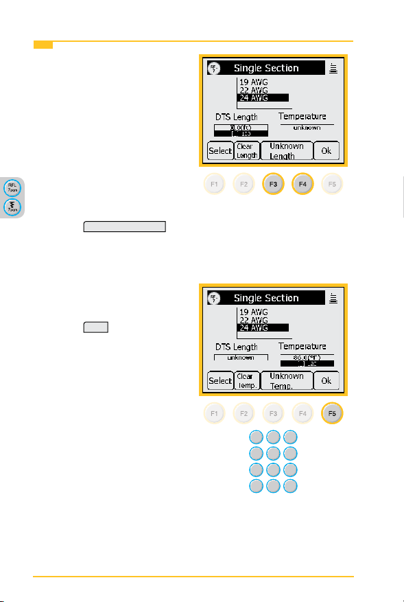
6. The rst parameter is
the gauge. Use the Up
and Down arrow keys to
highlight the gauge of your
cable.
Press
Select
to choose the
cable length.
63
Page 64
Measurement Functions 3M™ Dynatel™ Advanced Modular System 965AMS
RFL>Separate-Pair, Single-Section Operation
Special Requirement: Enter
the cable temperature or the
length, but not both. Only one
parameter can be entered.
There must be one unknown to
solve the calculation.
For this example, we will use
the cable temperature as the
known value and the length
will not be entered.
7. Press
Unknown Length
to enter an unknown
length and highlight the
Temperature section.
8. Enter the temperature using
the blue keys.
Press
OK
to return to the
main RFL screen.
64
Page 65

3M™ Dynatel™ Advanced Modular System 965AMS Measurement Functions
RFL>Separate-Pair, Single-Section Operation
9. Press
to review the
Test
settings.
10. This screen shows the
test lead hook-ups and the
settings you have selected.
Start
Press
to begin the
test.
11. If the hook-up is not
correct, you will see an
error message on the wiring
diagram at the point of the
error.
65
Page 66

Measurement Functions 3M™ Dynatel™ Advanced Modular System 965AMS
RFL>Separate-Pair, Single-Section Operation
12. During the measurement
process, a bar graph of the
null voltage for DTS and
then for DTF will be visible
on the screen.
13. The results of the
measurements are displayed
on the screen.
DTS is the distance to the
strap.
DTF is the distance to the
fault.
DSTF is the distance from
the strap to the fault.
This screen also displays
the value of the fault.
In some situations it may
be more helpful to use the
resistance values instead of
the distance values. Press
Convert to ohms
to use the
resistance values.
66
Page 67

3M™ Dynatel™ Advanced Modular System 965AMS Measurement Functions
RFL>Separate-Pair, Single-Section Operation
14. Press
Convert to distance
to
convert the resistance back
to distance.
RFL>Separate-Pair, Multi-Section Operation
1. Use the Auto test
the Ohmmeter
, or
, to
determine the type of fault.
2. Press the blue key to
enter the RFL function.
Press
Select
until the Fault
section is highlighted. Use
the up and down arrow keys
to select the type of fault
that you have. The options
include:
Tip Cross, Ring Cross, Wet
Pulp, T-G, R-G, Short
This example will show a
Ring-Ground fault.
Press
Select
to move to
the Pair section.
67
Page 68

Measurement Functions 3M™ Dynatel™ Advanced Modular System 965AMS
RFL>Separate-Pair, Multi-Section Operation
3. Use the up and down arrow
keys to select Separate Pair.
Select
Press
to move to
the Multiple-Single section.
4. Use the up and down arrow
keys to select Multiple
sections of cable that have
more than one gauge.
5. Press
Setup
to dene the
sections.
68
Page 69

3M™ Dynatel™ Advanced Modular System 965AMS Measurement Functions
RFL>Separate-Pair, Multi-Section Operation
6. Use the up and down
arrow keys to select a
section. Press
Edit Section
to choose the measurement
parameters.
7. The rst parameter is
the gauge. Use the Up
and Down arrow keys to
highlight the gauge of your
cable.
Press
Select
to highlight
the section length section.
69
Page 70

Measurement Functions 3M™ Dynatel™ Advanced Modular System 965AMS
RFL>Separate-Pair, Multi-Section Operation
8. Use the blue keys to enter
the section length.
Select
Press
to move to
the Temp section.
9. Use the blue keys to enter
the cable temperature.
Press
OK
to return to the
Multiple Gauge screen.
70
Page 71

3M™ Dynatel™ Advanced Modular System 965AMS Measurement Functions
RFL>Separate-Pair, Multi-Section Operation
10. Use the up and down arrow
keys to select the next
section. Press
Edit Section
to choose the measurement
parameters.
11. You can add a load coil
to the calculations. Press
Load Coil
to add the H88
load coil to the section.
You can add as many load
coils as you need, but each
one must be in a different
section on the screen.
12. Press OK to store the
load coil and return to the
Multiple Gauge screen.
71
Page 72

Measurement Functions 3M™ Dynatel™ Advanced Modular System 965AMS
RFL>Separate-Pair, Multi-Section Operation
13. Use the up and down arrow
keys to select the next
section. Press
Edit Section
to choose the measurement
parameters.
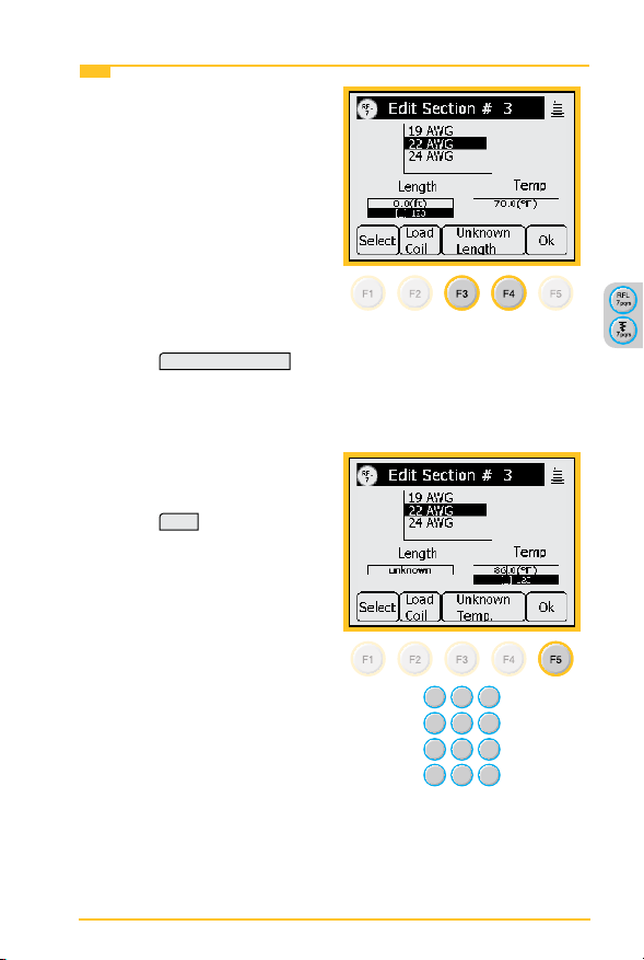
14. Use the Up and Down
arrow keys to highlight the
gauge of your cable.
Press
Select
to highlight
the section length section.
72
Page 73

3M™ Dynatel™ Advanced Modular System 965AMS Measurement Functions
RFL>Separate-Pair, Multi-Section Operation
Special Requirement: Enter
the cable temperature or the
length, but not both. Only one
parameter can be entered.
There must be one unknown to
solve the calculation.
For this example, we will use
the cable temperature as the
known value and the length
will not be entered.
15. Press
Unknown Length
to
enter an unknown length
and move to the Temp
section.
16. Use the blue keys to enter
the cable temperature.
Press
OK
to return to the
Multiple Gauge screen.
73
Page 74

Measurement Functions 3M™ Dynatel™ Advanced Modular System 965AMS
RFL>Separate-Pair, Multi-Section Operation
17. Press
OK
again to return
to the main RFL screen.
18. Press
to review the
Test
settings.
19. This screen shows the
test lead hook-ups and the
settings you have selected.
Start
Press
to begin the
test.
74
Page 75

3M™ Dynatel™ Advanced Modular System 965AMS Measurement Functions
RFL>Separate-Pair, Multi-Section Operation
20. If the hook-up is not
correct, you will see an
error message on the wiring
diagram at the point of the
error.
21. During the measurement
process, a bar graph of the
null voltage for DTS and
then for DTF will be visible
on the screen.
75
Page 76

Measurement Functions 3M™ Dynatel™ Advanced Modular System 965AMS
RFL>Separate-Pair, Multi-Section Operation
22. The results of the
measurements are displayed
on the screen.
DTS is the distance to the
strap.
DTF is the distance to the
fault.
DSTF is the distance from
the strap to the fault.
This screen also displays
the value of the fault.
In some situations it may
be more helpful to use the
resistance values instead of
the distance values. Press
Convert to ohms
to use the
resistance values.
23. Press
Convert to distance
to
convert the resistance back
to distance.
76
Page 77

3M™ Dynatel™ Advanced Modular System 965AMS Measurement Functions
RFL>Single-Pair, Single-Section Operation
1. Use the Auto test
the Ohmmeter
, or
, to
determine the type of fault.
2. Press the blue key to
enter the RFL function.
Press
Select
until the Fault
section is highlighted. Use
the up and down arrow keys
to select the type of fault
that you have. The options
include:
Tip Cross, Ring Cross, Wet
Pulp, T-G, R-G, Short
This example will show a
Ring-Ground fault.
Press
Select
to move to
the Pair section.
77
Page 78

Measurement Functions 3M™ Dynatel™ Advanced Modular System 965AMS
RFL>Single-Pair, Single-Section Operation
3. Use the up and down arrow
keys to select Single Pair.
Select
Press
to move to
the Multiple-Single section.
4. Use the up and down
arrow keys to select Single
Section.
5. Press
Setup
to choose the
measurement parameters.
78
Page 79

3M™ Dynatel™ Advanced Modular System 965AMS Measurement Functions
RFL>Single-Pair, Single-Section Operation
6. The rst parameter is
the gauge. Use the Up
and Down arrow keys to
highlight the gauge of your
cable.
Press
Select
to choose the
cable length.
Special Requirement: Enter
the cable temperature or the
length, but not both. Only one
parameter can be entered.
There must be one unknown to
solve the calculation.
For this example, we will use
the cable temperature as the
known value and the length
will not be entered.
7. Press
Unknown Length
to
enter an unknown length
and move to the Temp
section.
79
Page 80

Measurement Functions 3M™ Dynatel™ Advanced Modular System 965AMS
RFL>Single-Pair, Single-Section Operation
8. Enter the temperature using
the blue keys.
OK
Press
to return to the
main RFL screen.
9. Press
settings.
80
to review the
Test
Page 81

3M™ Dynatel™ Advanced Modular System 965AMS Measurement Functions
RFL>Single-Pair, Single-Section Operation
10. This screen shows the
test lead hook-ups and the
settings you have selected.
Start
Press
to begin the
test.
11. If the hook-up is not
correct, you will see an
error message on the wiring
diagram at the point of the
error.
12. During the measurement
process, a bar graph of the
null voltage for DTS and
then for DTF will be visible
on the screen.
81
Page 82

Measurement Functions 3M™ Dynatel™ Advanced Modular System 965AMS
RFL>Single-Pair, Single-Section Operation
13. The results of the
measurements are displayed
on the screen.
DTS is the distance to the
strap.
DTF is the distance to the
fault.
DSTF is the distance from
the strap to the fault.
This screen also displays
the value of the fault.
In some situations it may
be more helpful to use the
resistance values instead of
the distance values. Press
Convert to ohms
to use the
resistance values.
14. Press
Convert to distance
to
convert the resistance back
to distance.
82
Page 83

3M™ Dynatel™ Advanced Modular System 965AMS Measurement Functions
RFL>Single Pair, Multi-Section Operation
1. Use the Auto test
the Ohmmeter
, or
, to
determine the type of fault.
2. Press the blue key to
enter the RFL function.
Press
Select
until the up
and down arrow keys are in
the Fault section. Use the
up and down arrow keys
to select the type of fault
that you have. The options
include:
Tip Cross, Ring Cross, Wet
Pulp, T-G, R-G, Short
This example will show a
Ring-Ground fault.
Press
Select
to move to
the Pair section.
83
Page 84

Measurement Functions 3M™ Dynatel™ Advanced Modular System 965AMS
RFL>Single Pair, Multi-Section Operation
3. Use the up and down arrow
keys to select Single Pair.
Select
Press
to move to
the Multiple-Single section.
4. Use the up and down arrow
keys to select Multiple
sections of cable that have
more that one gauge.
5. Press
Setup
to choose the
measurement parameters.
84
Page 85

3M™ Dynatel™ Advanced Modular System 965AMS Measurement Functions
RFL>Single Pair, Multi-Section Operation
6. Use the up and down
arrow keys to select a
section. Press
Edit Section
to choose the measurement
parameters.
7. The rst parameter is
the gauge. Use the Up
and Down arrow keys to
highlight the gauge of your
cable.
Press
Select
to highlight
the section length section.
85
Page 86

Measurement Functions 3M™ Dynatel™ Advanced Modular System 965AMS
RFL>Single Pair, Multi-Section Operation
8. Use the blue keys to enter
the section length.
Select
Press
to move to
the Temp section.
9. Use the blue keys to enter
the cable temperature.
Press
OK
to return to the
Multiple Gauge screen.
86
Page 87

3M™ Dynatel™ Advanced Modular System 965AMS Measurement Functions
RFL>Single Pair, Multi-Section Operation
10. Use the up and down arrow
keys to select the next
section. Press
Edit Section
to choose the measurement
parameters.
11. You can add a load coil
to the calculations. Press
Load Coil
to add the load
coil to the section. You
can add as many load
coils as you need, but each
one must be in a different
section on the screen.
12. Press OK to store the
load coil and return to the
Multiple Gauge screen.
87
Page 88

Measurement Functions 3M™ Dynatel™ Advanced Modular System 965AMS
RFL>Single Pair, Multi-Section Operation
13. Use the up and down arrow
keys to select the next
section. Press
Edit Section
to choose the measurement
parameters.
14. Use the Up and Down
arrow keys to highlight the
gauge of your cable.
Press
Select
to highlight
the section length section.
88
Page 89
3M™ Dynatel™ Advanced Modular System 965AMS Measurement Functions
RFL>Single Pair, Multi-Section Operation
Special Requirement: Enter
the cable temperature or the
length, but not both. Only one
parameter can be entered.
There must be one unknown to
solve the calculation.
For this example, we will use
the cable temperature as the
known value and the length
will not be entered.
15. Press
Unknown Length
to
enter an unknown length
and move to the Temp
section.
16. Use the blue keys to enter
the cable temperature.
Press
OK
to return to the
Multiple Gauge screen.
89
Page 90

Measurement Functions 3M™ Dynatel™ Advanced Modular System 965AMS
RFL>Single Pair, Multi-Section Operation
17. Press
OK
again to return
to the main RFL screen.
18. Press
Test
to review the
settings.
19. This screen shows the
test lead hook-ups and the
settings you have selected.
Start
Press
to begin the
test.
90
Page 91

3M™ Dynatel™ Advanced Modular System 965AMS Measurement Functions
RFL>Single Pair, Multi-Section Operation
20. If the hook-up is not
correct, you will see an
error message on the wiring
diagram at the point of the
error.
21. During the measurement
process, a bar graph of the
null voltage for DTS and
then for DTF will be visible
on the screen.
91
Page 92

Measurement Functions 3M™ Dynatel™ Advanced Modular System 965AMS
RFL>Single Pair, Multi-Section Operation
22. The results of the
measurements are displayed
on the screen.
DTS is the distance to the
strap.
DTF is the distance to the
fault.
DSTF is the distance from
the strap to the fault.
This screen also displays
the value of the fault.
In some situations it may
be more helpful to use the
resistance values instead of
the distance values. Press
Convert to ohms
to use the
resistance values.
23. Press
Convert to distance
to
convert the resistance back
to distance.
92
Page 93

3M™ Dynatel™ Advanced Modular System 965AMS Measurement Functions
RFL>Wet Pulp
Use this function to nd the approximate distance to a resistance
fault when both wires in a pair are faulted at the same place
and a separate good pair or a single common conductor is not
available.
RFL>Wet Pulp>Hook-Up
RED
Wire With Lower Resistance ValueWire With Lower Resistance Value
GRN
Common/Ground
Common/Ground
BLK
Wire With Higher Resistance Value
Wire With Higher Resistance Value
1. The resistance faults must be common to the reference
(Green) conductor. Use the ohmmeter function to measure
the resistance on each side of the pair to the reference
conductor.
2. The lower value fault should be connected to the Red test
lead.
3. The higher value fault should be connected to the Black test
lead.
4. The Green test lead should be connected to the reference
conductor, usually the shield or ground.
93
Page 94

Measurement Functions 3M™ Dynatel™ Advanced Modular System 965AMS
RFL>Wet Pulp> Requirements
Note: All of the following conditions must be met or this
function does not apply:
1. One fault must be at least twice the ohms value of the other
fault. For example, a 5 kΩfault has twice the value of a
10 kΩfault.
2. The sum of both faults must be at least 100 times the loop
resistance of the pair. For example, if the loop resistance is
50 Ω, the sum of the faults must be 5 kΩor greater. You may
continue with the test, but the results may have a reduced
accuracy.
3. The 965AMS checks to see if the resistance of the loop
is less than 7 kΩ. If the resistance is greater than 7 kΩ,
the distance to strap may be too long or the strap is not
connected,
RFL>Wet Pulp>Operation
1. Press the blue
key to
enter the RFL function.
Use the up and down keys
to select Wet Pulp.
Press
Setup
to select the
gauge of the pair.
94
Page 95

3M™ Dynatel™ Advanced Modular System 965AMS Measurement Functions
RFL>Wet Pulp>Operation
2. Use the up and down arrow
keys to select the gauge of
the pair.
Press
Select
Unknown Temp.
or
to highlight
the temperature eld.
3. Use the blue keypad to
enter the cable temperature.
Press
OK
to continue.
95
Page 96

Measurement Functions 3M™ Dynatel™ Advanced Modular System 965AMS
RFL>Wet Pulp>Operation
4. The Wet Pulp test rst
makes a measurement with
the far-end open.
Press
Start
to start the test.
5. Strap the pair at the far end,
then press
Continue
.
Note: The “Opens Ratio” value
displayed on the screen is the
ratio of R1/(R2+R1) times
100. This value is used by
some companies as part of the
measurement. It is not needed
to calculate the distance to the
fault.
6. The test results are shown
in ohms.
Press
Dist.
to convert the
ohms to the distance to the
fault.
96
Page 97

3M™ Dynatel™ Advanced Modular System 965AMS Measurement Functions
RFL>Wet Pulp>Operation
7. DTS—Distance to the strap
(far end).
DTF—Distance to the fault.
DSTF—Distance from the
strap to the fault.
Press
Avg. Result
to view a
summary of test results.
8. Use the results of this test
to nd the distance or run
the test multiple times and
the tester will average the
distances.
RFL>Wet Pulp>Error Screens
1. Swap the Red and Black
test leads.
97
Page 98

Measurement Functions 3M™ Dynatel™ Advanced Modular System 965AMS
RFL>Wet Pulp>Error Screens
2. The strap at the far-end is
open. There should be a
solid short at the far-end.
3. The tester checks to see
that the sum of the faults
is more than 100 times the
loop resistance. You may
Continue
press
with the
test, but the results may
have a reduced accuracy.
98
Page 99

3M™ Dynatel™ Advanced Modular System 965AMS Measurement Functions
DSL (Digital Subscriber Line)
The DSL functions include: DSL Loss, DSL Noise, DSL
Spectrum Analyzer, Resistive Balance, and DSL Impulse Noise.
DSL>DSL Loss
Use DSL Loss function to measure the amount of loss in a
circuit at a specic frequency. This is typically accomplished by
sending tone with another 965AMS tester, a 3M
End Device (FED), or test equipment that is capable of sending
wideband tone from 20 kHz to 30 MHz.
DSL>DSL Loss>Hook-Up
RED
Ring (A)Ring (A)
BLK
Tip (B)
Tip (B)
™
Dynatel™ Far
99
Page 100
Measurement Functions 3M™ Dynatel™ Advanced Modular System 965AMS
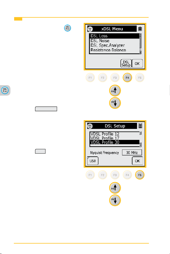
DSL>DSL Loss>Operation
1. Press the blue DSL
key
to enter the DSL function.
Use the up and down arrow
keys to select DSL Loss.
Use a tone source at the
far end that is capable of
sending a known output
level such as a 965AMS
tester. Use 0dBm as the
output level or follow your
method of test.
2. Press
DSL Setup
to select
the type of service.
3. Use the up and down
arrow keys to select the
type of service that you are
measuring.
4. Press
OK
when nished.
100
 Loading...