

Page 1
3
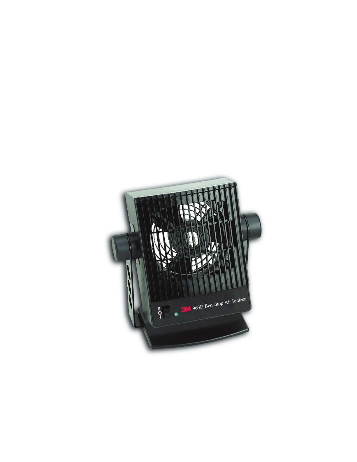
Benchtop Air Ionizers
963/963E
Instructions
March 2007
78-9100-2391-6
Page 2

Table of Contents
Safety Information ...........................................................................................................................3
1. Description ...................................................................................................................................4
2. Performance .................................................................................................................................4
3. Power Requirements ....................................................................................................................4
4. Installation ....................................................................................................................................4
5. Operation ......................................................................................................................................4
6. Maintenance .................................................................................................................................5
7. Performance Verification ..............................................................................................................5
8. Physical Characteristics ...............................................................................................................6
Customer and Technical Service ......................................................................................................6
2
Page 3

Safety Information
Intended Use
The 3M™ Benchtop Air Ionizers 963/963E are designed to generate and deliver a stream of ionized air. Its
intended use is to neutralize excess static electricity buildup on electronic devices and work surfaces. It is meant
to function as a stand alone device. The Benchtop Air Ionizers 963/963E are not intended to supplant proper
grounding of personnel as the preferred method of controlling electrostatic buildup and preventing hazardous
discharge.
CAUTION
• The 963 ionizer is designed for use in those areas using AC 120V electrical service, while the 963E
ionizer runs off of DC24V power, supplied by a universal power supply capable of converting AC 100240V electrical service. Usage of either unit with the incorrect electrical voltage could result in incorrect
performance and an unsafe operating condition.
• The 963/963E has no user-serviceable parts. Do not remove the grill or disassemble the unit in any
way. If service other than that recommended in this manual is needed, please contact 3M for information.
UNAUTHORIZED SERVICE WILL VOID THE WARRANTY.
• The 963/963E is NOT designed for usage in hazardous environments where the possibility of explosion
or fire exists.
• When cleaning the 963/963E housing or emitter points, verify that the unit is off and disconnected from
electrical power. Collected dirt on this unit should be removed regularly to prevent accumulation that may
result in fire.
• Class 1 equipment.
Explanation of Symbols
- Caution: refer to user instruction manual.
- High voltage present inside unit.
Read and understand all safety information before installing and operting this equipment.
3
Page 4

1.0 Description
The 3M™ Benchtop Air Ionizers 963/963E are self-contained ionizing air blowers designed to remove
static charges from non-conductive objects. The proprietary circuitry contained in the blower generates
equal levels of positive and negative ions, and maintains correct balance despite variations in line voltage,
fan speed, and emitter point condition. The 963/963E ionizers are equipped with a two speed fan which
allows the user to select the amount of ionized air to be delivered to the target object. In addition, the
housing of the 963/963E ionizers are constructed of a static-dissipative plastic, which minimizes the
amount of static charge that can build up on the outside surface of the unit.
2.0 Performance
The benchtop air ionizers 963 reduce a static charge of ± 1000 V to ± 100 V in less than one second
(the discharge time) at a distance of one foot (30 cm) using the high fan speed. The 963E ionizer will
discharge in under 2 seconds. Testing is performed in accordance with the ionization standard ANSI/ESD
S3.1 and IEC standard 61340-5-1.
3.0 Power Requirements
The 963 ionizers require AC 120V power and is supplied with a 6 ft. (1.8 m) power cord with a North
American style three-prong plug. The 963E ionizers require DC 24V power, which is supplied through a
Mini DIN connector on the back of the unit. The 963E ionizers are packaged with a universal power supply,
capable of converting AC 100V-240V, 50/60 Hz into DC 24V. The universal power supply uses a 3 ft. (0.9
m) cord to connect to the ionizer, and has an IEC 320 input socket for incoming power. Please note that,
due to the multitude of locations worldwide in which the 963E ionizers can be used, it does NOT come
supplied with a power cord to connect the universal power supply to local electrical service. The customer
is asked to please provide an appropriate power cord that is capable of connecting local electrical service
to the universal power supply. The 963E ionizers should only be used with the included power supply
(PowDec Part No. WP10240I).
4.0 Installation
4.1 The benchtop air ionizers 963/963E mount easily in a variety of positions using the provided tilting
bracket/stand. Place the unit on the work surface and point it at the area or object to be neutralized.
Alternatively, the mounting bracket may be attached directly to or above the workstation, or on another
supporting structure. Please note that placement of the 963/963E ionizers are important in determining
its effectiveness. The distance from the target object, and fan speed affect the ionizer’s performance. As
distance increases or fan speed is reduced, the discharge time will increase.
4.2 Determine the location of an appropriate electrical outlet. For the 963 ionizer, connect the power cord
to the ionizer, and insert the other end of power cable into the appropriate electrical outlet. For the 963E
ionizer, connect the universal power supply to the ionizer, using the Mini DIN connector. Then, using the
appropriate electrical power cord, connect the universal power supply to an electrical outlet.
5.0 Operation
The three position rocker switch on the front of the unit is the POWER switch. The center switch position
(marked O) is the OFF position. The upper and lower switch positions (marked II and I) turn the unit on to
HIGH and LOW fan speeds. Use this switch to turn the unit on and to select the desired fan speed. A green
monitor light is also illuminated respectively on the front of the unit, which indicates that the power switch
is in one of the ON positions, and that the ionizer is now in use.
4
Page 5

6.0 Maintenance
Occasional cleaning of the case and of the emitter points are the only routine maintenance procedures
required.
6.1 Cleaning the case: wipe the case with a soft cloth moistened with water. If a stronger cleaning
solution is required, mild detergent or alcohol may be used. Do not use solvents that will attack the plastic
case.
6.2 Cleaning the emitter points: when the emitter points become dirty, the internal circuitry of the ionizer
will be automatically adjusted to emit an equal amount of positive and negative ions. Contamination
on the needlepoint, however, may inhibit ionization to a limited degree. The emitter points are located
between the fan blades and the rear grill. A jet of clean, compressed air can be used to remove dirt on
emitter points. If a more rigorous cleaning method is needed to remove particulate, clean the points with
a cotton swab. Access to the points is available through the rear grill. Be careful not to damage the points
during cleaning.
7.0 Performance Verification
The 3M™ Benchtop Air Ionizers 963/963E are factory adjusted to provide optimum performance. Further
adjustment in the field is not possible. However, the following instructions can be followed to determine
whether the Ionizer is performing to specification. The testing follows the procedure outlined in the
standard for Ionization, ANSI/ESD S3.1. Please refer to this standard for more complete information.
7.1 Equipment Needed
3M™ Charge Analyzer 711 or equivalent charge plate monitor (CPM). If an alternate CPM is used, please
refer to its Operating Manual for details on how to perform the following instructions.
7.2 Static Discharge Time
The benchtop air ionizer 963 will reduce the charge on the 6 in. x 6 in. square isolated metal plate
on the CPM from ± 1000 volts to ± 100 volts in less than 1 second (high fan speed). The 963E ionizer will
discharge in less than 2 seconds. The metal plate for the CPM must be located at a distance of one foot
(30 cm) from the ionizer and centered in the air stream.
7.21 Attach the flat plate electrode to the 711 analyzer. Refer to the owner’s manual for the 711 analyzer for
complete operating instructions.
7.22 Place the 711 analyzer on its side allowing for viewing of the display. Position the 711 analyzer so that the
plate is parallel to the ionizer at a distance of one foot. The plate of the 711 analyzer should be centered
(up & down, left & right) in the air stream. It may be necessary to raise the ionizer from the surface to
allow for centering on the 711 analyzer charge plate. If so, use a block of appropriate height to elevate the
711 analyzer. Please note that the plate must be kept totally isolated from ground and that the edge of the
plate should be raised up a minimum distance of 3 in. from the work surface. This is illustrated in Fig. 11
of ANSI/ESD-S3.1.
7.23 Turn on the ionizer at high speed and allow it to run for five minutes.
7.24 Charge the plate positive as described in the 711 analyzer operating instructions for “Static Decay Time”
mode. Observe the discharge time indicated on the 711 analyzer. Repeat this step for negative polarity.
7.3 Ion Balance
The ionized air blower will stay within an offset voltage of +/-15 volts (max. deviation from zero) at a
distance of one foot, when measured using the following procedure.
7.31 Position the ionizer and CPM as stated above in Section 7.22.
7.32 Turn on the ionizer at high speed and allow it to run for five minutes.
7.33 Use a ground wire to ground the charge plate of the 711 analyzer. This will remove any/all residual charge
present on the charge plate. If the CPM does not zero, adjust the zero control.
7.34 Remove the ground wire and observe the display on the 711 analyzer. The voltage (either ±) observed
during this time is the “offset voltage” and is a measure of instantaneous ion imbalances produced by the
ionizer.
5
Page 6

8.0 3M™ Benchtop Air Ionizer 963/963E Physical Characteristics
Typical Properties
Item 963 963E
Power Ratings AC 120V 60Hz 0.2 A 20W DC 24V 0.42 A 10W
Power Inlets IEC 320 Socket Mini DIN Socket
Power Transformer _
Power Outlet Cord 6 ft. (1.8 m) cord with IEC 320 and
Dimensions
(with mounting base)
Weight 2.5 lb. (1.1 kg) 2.5 lb. (1.1 kg)
Air Velocity**
low speed
high speed
Static Discharge Time*
@1 ft. (30 cm)
Certifications and Approvals UL, C-UL, NOM UL, C-UL, NOM, CE
Warranty 1 year 1 year
NEMA 5-15 plugs
7 in. W x 9 in. H x 4 in. D
(18 cm W x 23 cm H x 10 cm D)
350 ft/min
500 ft/min
< 1 second < 2 seconds
Output: DC24V, 0.5A
* When tested according to ANSI/ESD S3.1-1991 at high fan speed
** Air Velocity tested at 1 ft. distance from center of fan to Anemometer
through included universal power transformer
Input: AC 100V-240V, 0.4A, 50/60 Hz
into IEC320 Socket
3 ft. (0.9 m) cord with Mini DIN plug
not included
7 in. W x 9 in. H x 4 in. D
(18 cm W x 23 cm H x 10 cm D)
190 ft/min
290 ft/min
Customer and Technical Service
Within the U.S.:
Customer service and technical support can be obtained by calling the 3M Electronic Solutions Division
Customer Service: (800) 328-1368
Technical Support: (512) 984-3200
Outside of the U.S.:
For customer service and technical support, please contact your local representative of the 3M Electronic Solutions Division.
3M is a trademark of 3M Company.
Important Notice
PRODUCT USE: All statements, technical information and recommendations contained in this document are based upon tests or
experience that 3M believes are reliable. However, many factors beyond 3M’s control can affect the use and performance of a 3M
product in a particular application, including the conditions under which the product is used and the time and environmental conditions
in which the product is expected to perform. Since these factors are uniquely within the user’s knowledge and control, it is essential
that the user evaluate the 3M product to determine whether it is fit for a particular purpose and suitable for the user’s application.
Warranty; Limited Remedy; Limited Liability.
3M’s product warranty is stated in its Product Literature available upon request. 3M MAKES NO OTHER WARRANTIES INCLUDING,
BUT NOT LIMITED TO, ANY IMPLIED WARRANTY OF MERCHANTABILITY OR FITNESS FOR A PARTICULAR PURPOSE. If this
product is defective within the warranty period stated above, your exclusive remedy shall be, at 3M’s option, to replace or repair the
3M product or refund the purchase price of the 3M product. Except where prohibited by law, 3M will not be liable for any indirect,
special, incidental or consequential loss or damage arising from this 3M product, regardless of the legal theory asserted.
3
3M Electronic Solutions Division
6801 River Place Blvd.
Austin, TX 78726-9000
800/328-1368
www.3M.com/electronics
Please recycle. Printed in USA.
© 3M 2007
78-9100-2391-6
 Loading...