

Page 1
Machinery 2006/42/EC
Electrical Safety BS EN 60335-1:2002
+ A15:2011
EMC EN 61000-6-1:2007
EN 61000-6-3:2007
+ A1:2011
EN 61000-3-3:2008
EN 61000-3-2:2006
+ A2:2009
1
User Instruction Manual
POWERED CLIMB ASSIST SYSTEM
Table 1 – Powered Climb Assist System Components
6160024
9506038
9506929
9506930
9507098
6160026
Power Cord, BS 546 Type M South Africa, India
Power Cord, NEMA 5-15P United States, Canada, Mexico
Power Cord, AS 3112 Australia, New Zealand, China
Power Cord, CEE 7/7 Europe
6160024 & 6160026 Cable Grips
Cable Grip Zinc Plated Alloy Steel
1
Lanyard Nylon, Elastic Web
Carabiners Zinc Plated Alloy Steel,
3,600 lb. (16 kN) Gate
6160025 - Portable Motor Control Unit
Weight 20 lb (9 kg)
Power Supply Range 110 - 240 VAC, 50-60 Hz
Climb Assist Force Range 55 - 120 lb (25 - 55 kg)
Motor Control Panel Functions
Press to switch power ON/OFF.
Press to decrease Climb Assist Force.
Press to increase Climb Assist Force
Press and hold Plus and Minus buttons to
switch the direction of cable travel. Left
LED should illuminate for systems with
the Drive Bracket opposite the climber.
Right LED should illuminate for systems
with the Drive Bracket on the same side
as the climber.
9506038
9506929
6160029
9506930
9507070
9507098
9507749
6160024
6160026
6160051
Form No: 5903807 Rev: B
Date of Publication: 06/29/2016
© Copyright 2016, 3M
Page 2

Page 3
2
1
D
D
C
B
C
A
A
1
B
2 3
4
E
F
B
E
G
5
6
3
Page 4
3
2
1
4A
5
5
6
4A
4A
5
6
4A
4B
5
6
4B
6
6A 6B
4
Page 5
Original Instructions
WARNING: This product must be used in conjunction with a Fall Arrest System. The user must follow the manufacturer’s instructions for
each component of the system. These instructions must be provided to the user of this equipment. The user must read and understand these
instructions before using this equipment. Manufacturer’s instructions must be followed for proper use and maintenance of this equipment.
Alterations or misuse of this product or failure to follow instructions may result in serious injury or death.
IMPORTANT: If you have questions on the use, care, or suitability of this equipment for your application, contact Capital Safety.
IMPORTANT: Before using the Portable Motor Control Unit for the fi rst time, record the product identifi cation information from the ID label
in the “Inspection and Maintenance Log (Table 1)”
DESCRIPTION
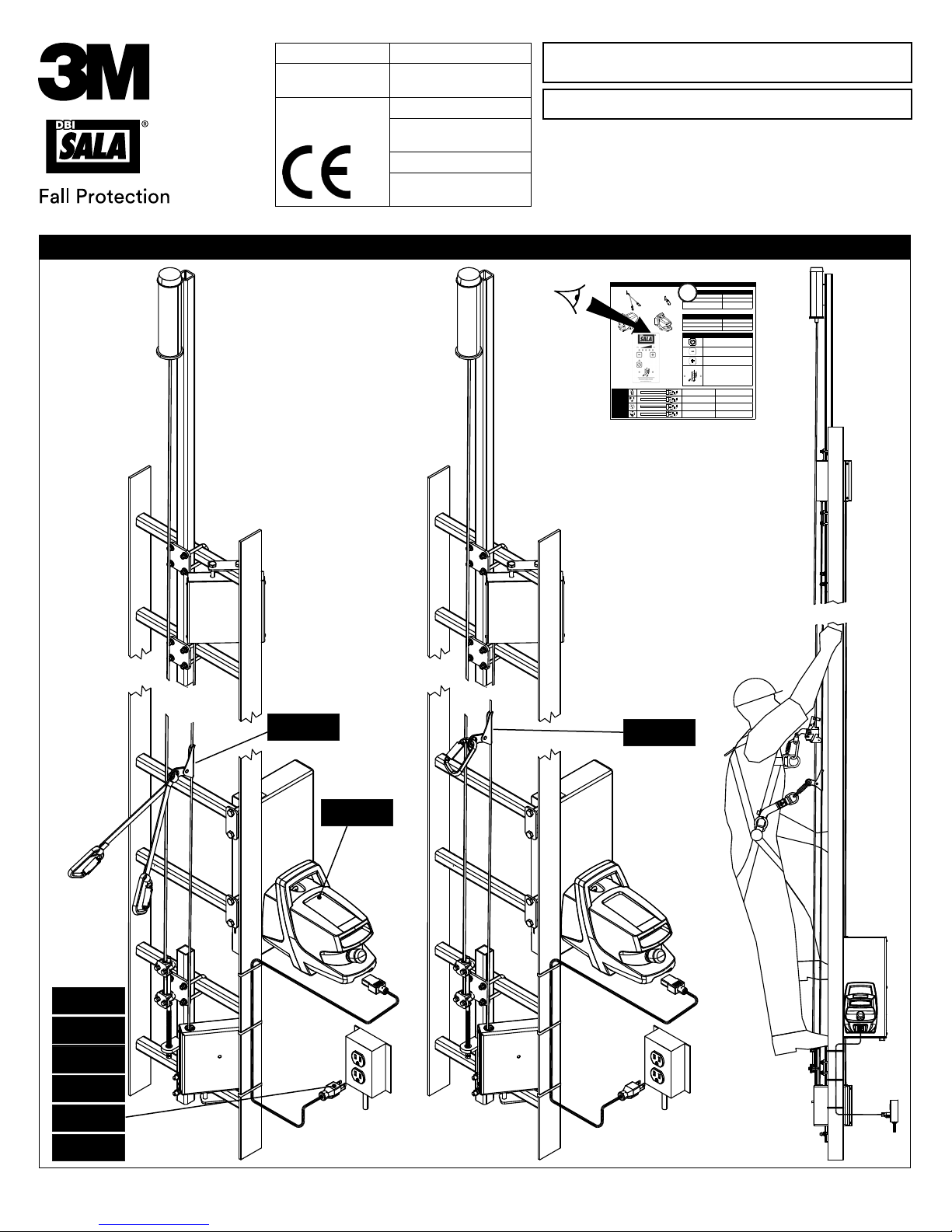
Figure 1 illustrates the Powered Climb Assist System (PCAS). The PCAS provides climbing assistance for individuals ascending
and descending interior fi xed ladders similar to those used in Wind Turbine Towers. The “Installation and Maintenance Manual
(5903806)” describes the components permanently installed at each site and their installation: Top and bottom End Bracket
Pulley assemblies attach to ladder rungs and support a Wire Rope Cable running up and down both sides of the ladder. A Drive
Bracket allows cable tensioning and is socketed for insertion of the Portable Motor Control.
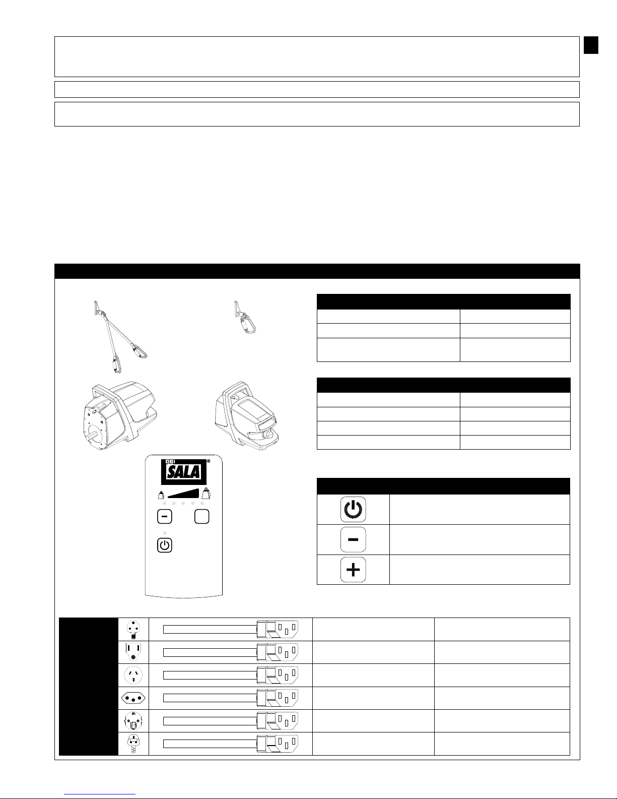
Table 1 shows transportable components of the Powered Climb Assist System which are used at multiple locations: The Portable
Motor Control Unit drives the Pulleys and Wire Rope Cable in a continuous loop to provide assist force for climbing up and down
the ladder. A Cable Grip attaches on the Wire Rope Cable and tethers to the climbers Full Body Harness. Internal adaptive
controls in the Motor Control allow the user to stop, ascend, and descend at will without operating a remote or switches. To
power the Motor Control Unit, multiple Power Cord options are available with plug ends appropriate for the locales of use.
Table 1 – Powered Climb Assist System Components
6160024
6160026
6160024 & 6160026 Cable Grips
Cable Grip Zinc Plated Alloy Steel
Lanyard Nylon
Carabiners Zinc Plated Alloy Steel,
3,600 lb. (16 kN) Gate
EN
9506038
9506929
9506930
kg
+
POWERED
CLIMB ASSIST
www.capitalsafety.com
6160051 - Portable Motor Control Unit
Weight 20 lb (9 kg)
Power Supply Range 110 - 240 VAC, 50-60 Hz
Climb Assist Force Range 55 - 120 lb (25 - 55 kg)
Sound Emission <70 dB(A)
kg
Power Cord, BS 546 Type M South Africa, India
Power Cord, NEMA 5-15P United States, Canada, Mexico
Power Cord, AS 3112 Australia, New Zealand, China
Motor Control Panel Functions
Press to switch power ON/OFF.
Press to decrease Climb Assist Force.
Press to increase Climb Assist Force
9507070
9507098
9507749
Power Cord, IEC 60906-1 Brazil
Power Cord, CEE 7/7 Europe
Power Cord, BS1363A United Kingdom
5
Page 6

1.0 APPLICATIONS
1.1 PURPOSE: The Powered Climb Assist System (PCAS) provides powered climb assistance while ascending or descending a
ladder. The PCAS is intended for use on interior fi xed ladders, such as those used in Wind Turbine Towers.
IMPORTANT: The PCAS should be used only as directed. It is not intended for lifting tools, equipment, spare parts, etc.
1.2 TRAINING: It is the responsibility of the users and purchasers of this equipment to assure they are familiar with these
instructions, trained in the correct care and use of, and are aware of the operating characteristics, application limitations,
and consequences of improper use of this equipment.
CAUTION: Training must be conducted without exposing the user to a fall hazard. Training should be repeated on a periodic basis.
1.3 RESCUE PLAN: When using this equipment and connecting subsystem(s), the employer must have a rescue plan and the
means at hand to implement and communicate that plan to users, authorized persons, and rescuers.
1.4 INSPECTION FREQUENCY:
The Powered Climb Assist System shall be inspected by the user before each use and,
additionally, by a competent person1 other than the user at intervals of no more than one year2. Inspection procedures
are described in the “Inspection and Maintenance Log” (Table 2). Results of each Competent Person inspection should be
recorded on copies of the “Inspection and Maintenance Log”.
2.0 REQUIREMENTS
Consider the following requirements when planning and installing the Powered Climb Assist System:
2.1 FALL ARREST SYSTEM: The Powered Climb Assist System is not certifi ed for Fall Arrest. It must be used in combination
with a Lad-Saf™ Ladder Safety System or similar Fall Arrest System certifi ed to the safety standards of the locale of
installation.
2.2 LADDER STRUCTURE: The ladder structure on which the Powered Climb Assist System is installed must meet
the structural and anchorage requirements of the accompanying Fall Arrest System. See the Fall Arrest System
manufacturer’s instructions for details. The PCAS is NOT intended for use with portable ladders or ladders exposed to the
environment. Ladders should be nearly vertical with a minimum slope of 75 degrees from horizontal for proper system
operation.
2.3 CAPACITY: The Powered Climb Assist System is designed for use by one person with a combined weight (clothing, tools,
etc.) of no more than 310 lbs (141 kg). Only one person should be attached to the PCAS at any time.
2.4 ELECTRICAL: The Plug-and-Play Motor Control Unit that powers the Powered Climb Assist System requires a 110-240
VAC, 50-60 Hz power source.
2.5 FULL BODY HARNESS: A Full Body Harness must be used with the Powered Climb Assist System. The harness must
have a frontal connection suitable for fall arrest when climbing a ladder. The fall arrest connection point must be above
the user’s center of gravity.
RECOMMENDED HARNESSES: Capital Safety recommends specifi c DBI-SALA Wind Energy Harnesses with integrated Climb Assist
Lanyards for use with the 6160026 Cable Grip. Contact Capital Safety or see www.CapitalSafety.com for details.
OTHER HARNESSES: Other harnesses may be used with the 6160024 Cable Grip Lanyard Assembly, but do not offer the same level
of comfort as the recommended DBI-SALA Wind Energy Harnesses.
WARNING: Body Belts are not authorized for use with the Powered Climb Assist System. Falls with a Body Belt may result in
unintentional release or possible suffocation due to insuffi cient body support.
2.6 HAZARDS: Use of this equipment in areas with hazards may require additional precautions to prevent injury to the user
or damage to the equipment. Hazards may include, but are not limited to; heat, chemicals, corrosive environments, high
voltage power lines, explosive or toxic gases, moving machinery, and sharp edges.
PINCH POINTS: Avoid touching areas where
the moving Wire Rope Cable passes through
grommets in the Bracket Assemblies when the
PCAS is running.
2.7 COMPONENT COMPATIBILITY: Capital Safety equipment is designed for use with Capital Safety approved components
and subsystems only. Substitutions or replacements made with non-approved components or subsystems may jeopardize
compatibility of equipment and may effect the safety and reliability of the complete system.
IMPORTANT: Equipment substitutions require written consent from Capital Safety.
1 Competent Person: One who is capable of identifying existing and predictable hazards in the surroundings or working conditions which are unsanitary,
hazardous, or dangerous to employees, and who has authorization to take prompt corrective measures to eliminate them.
2 Inspection Frequency: Extreme working conditions (harsh environments, prolonged use, etc.)may require increasing the frequency of competent person
inspections.
6
Page 7

2.8 CONNECTOR COMPATIBILITY: Connectors are considered to be compatible with connecting elements when they
have been designed to work together in such a way that their sizes and shapes do not cause their gate mechanisms
to inadvertently open regardless of how they become oriented. Contact Capital Safety if you have any questions about
compatibility.
Connectors (hooks, carabiners, and D-rings) must be capable of supporting at least 5,000 lbs. (22.2 kN). Connectors
must be compatible with the anchorage or other system components. Do not use equipment that is not compatible. Noncompatible connectors may unintentionally disengage (see Figure 4). Connectors must be compatible in size, shape, and
strength. Self-locking snap hooks and carabiners are required by ANSI Z359 and OSHA.
2.9 MAKING CONNECTIONS: Snap hooks and carabiners used with this equipment must be self-locking. Ensure all
connections are compatible in size, shape and strength. Do not use equipment that is not compatible. Ensure all
connectors are fully closed and locked.
Capital Safety connectors (snap hooks and carabiners) are designed to be used only as specifi ed in each product’s user’s
instructions. See Figure 5 for examples of inappropriate connections. Do not connect snap hooks and carabiners:
A. To a D-ring to which another connector is attached.
B. In a manner that would result in a load on the gate.
NOTE: Large throat snap hooks should not be connected to standard size D-rings or similar objects which will
result in a load on the gate if the hook or D-ring twists or rotates, unless the snap hook complies is equipped with
a 3,600 lb (16 kN) gate. Check the marking on your snap hook to verify that it is appropriate for your application.
C. In a false engagement, where features that protrude from the snap hook or carabiner catch on the anchor, and
without visual confi rmation seems to be fully engaged to the anchor point.
D. To each other.
E. Directly to webbing or rope lanyard or tie-back (unless the manufacturer’s instructions for both the lanyard and
connector specifi cally allows such a connection).
F. To any object which is shaped or dimensioned such that the snap hook or carabiner will not close and lock, or that
roll-out could occur.
G. In a manner that does not allow the connector to align properly while under load.
4 – Unintentional Disengagement 5 – Inappropriate Connections
If the connecting element to which a snap hook (shown) or carabiner attaches
is undersized or irregular in shape, a situation could occur where the connecting
element applies a force to the gate of the snap hook or carabiner. This force may
cause the gate (of either a self-locking or a non-locking snap hook) to open,
allowing the snap hook or carabiner to disengage from the connecting point.
Force is applied to the
Snap Hook.
Small ring or other
non-compatibly
shaped element
The Gate presses against
the Connecting Ring.
The Gate opens allowing
the Snap Hook to slip off.
7
Page 8

3.0 SYSTEM USE
IMPORTANT: Do not alter or intentionally misuse this equipment. Consult DBI-SALA when installing or using this equipment in combination
with components or subsystems other than those described in this manual. Some subsystem and component combinations may interfere with
the operation of this equipment.
3.1 INSPECTION BEFORE EACH USE: Before each use of the Powered Climb Assist System: Inspect the Motor Control
Unit and Cable Grip per the procedures defi ned in the “Inspection and Maintenance Log” (see Table 2). Inspect all other
components of the Powered Climb Assist System per the procedures defi ned in the “Installation and Maintenance Manual
(5903806)”. Inspect the required Fall Arrest System and Full Body Harness per the manufacturers’ instructions.
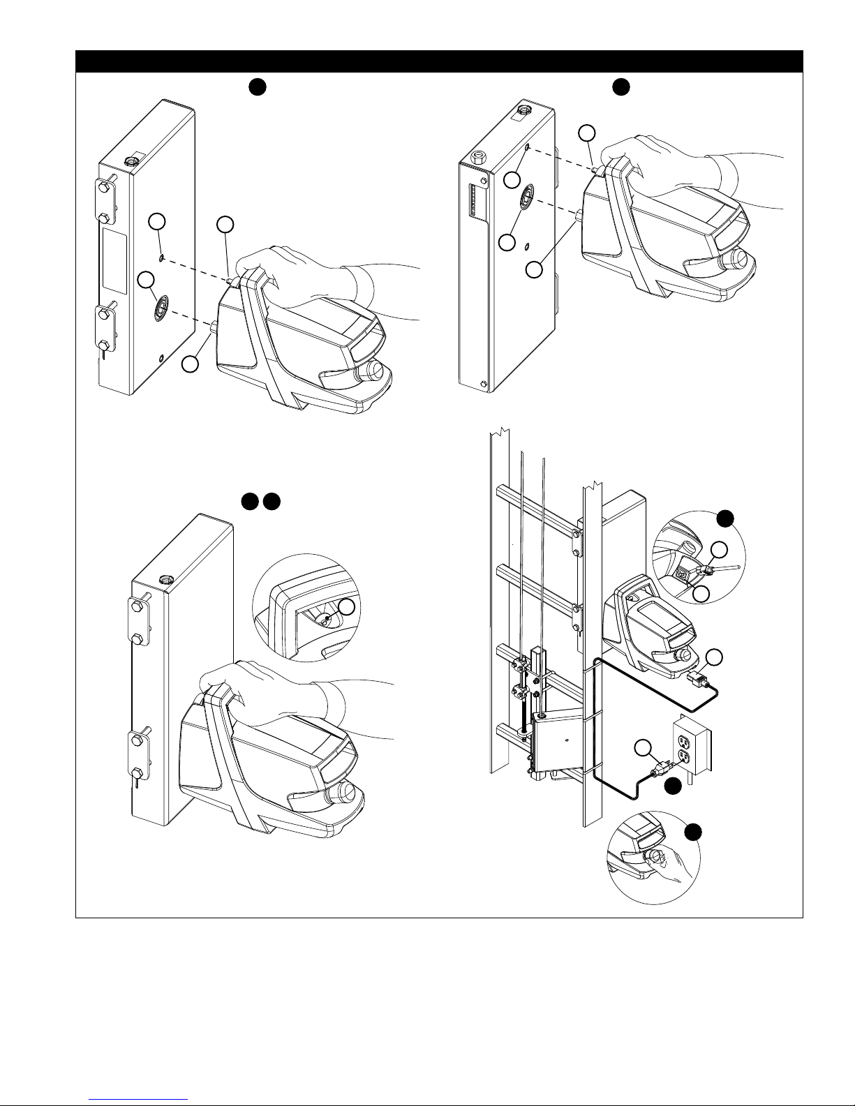
3.2 PORTABLE MOTOR CONTROL UNIT INSTALLATION: The Portable Motor Control Unit can be easily transported to
support multiple Powered Climb Assist Systems (PCAS) in multiple locations. Figure 2 illustrates installation of the Motor
Control Unit. To install the Motor Control Unit on the PCAS System’s Drive Bracket:
1. Lift the Motor Control by the handle and align the Drive Shaft (A) and Detent Pin (B) on the Motor Control with the
Drive Socket (C) and Locking Hole (D) on the Drive Bracket (see Figure 2-1).
2. Press the Detent Pin (B) and insert the Drive Shaft and Detent Pin all the way into the Drive Socket and Locking Hole
(see Figure 2-2).
3. Release the Detent Pin to secure the Motor Control on the Drive Bracket. Ensure that the Detent Pin is locked into
place. You should hear an audible click when the Detent Pin snaps into place.
4. Plug the Female Plug (E) on the Power Cord into the Power Socket on the Motor Control (F). (See Figure 2-4)
5. Plug the Male Plug on the Power Cord (G) into a Power Source at the site (see Figure 2-5).
6. Pull the Emergency Stop Button out (Figure 2-6). The Power Button (q) Light on the Motor Control will turn yellow.
7. Press the Power Button (q) on the Motor Control Keypad to turn on the Motor Control. The Power Button Light will
switch from yellow to green when the Motor Control is powered on.
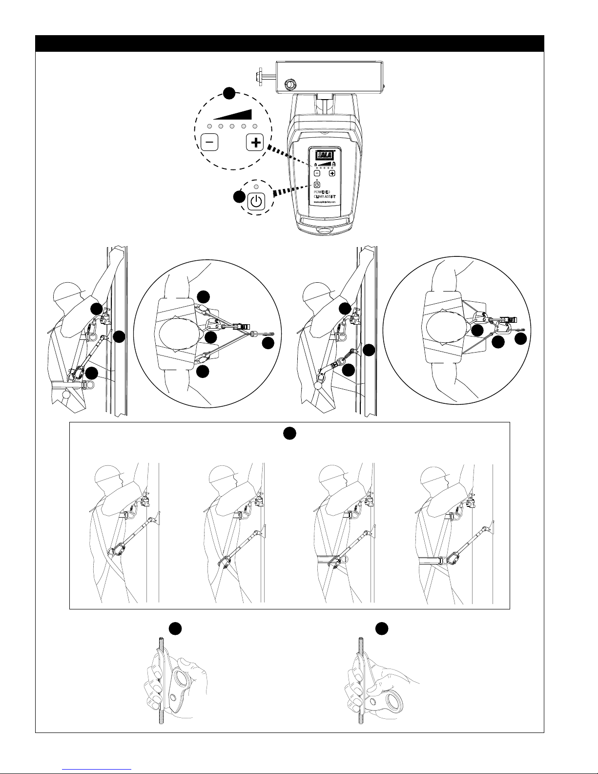
3.3 PCAS OPERATION: Figure 3 illustrates use of the Powered Climb Assist System. Operating procedures are as follows:
IMPORTANT: The Powered Climb Assist System (PCAS) is not certifi ed for Fall arrest. It must be used in combination with a Lad-
Saf™ Ladder Safety System or similar Fall Arrest System certifi ed to the safety standard(s) of the location of use.
EMERGENCY STOP: In the event of an emergency, the Motor Control is equipped with an Emergency Stop Button (see Figure 2-6).
It is recommended that one person be available at the base of the ladder when the PCAS is in operation.
1. If the Motor Control Unit is not on (Power Button Light is yellow), press the Power Button (q) on the Motor Control
Unit (Figure 3-1). The Power Button Light will change from yellow to green. (If the Power Button Light is not yellow or
green, verify that the Power Cord is plugged into the Motor Control and power source.)
2. Adjust the Climb Assist force: Press the Plus (=) Button to increase force, or press the Minus (-) to decrease force.
The fi ve red Climb Assist Force lights above the Plus and Minus Buttons indicate the current force setting. As force
increases, additional lights will turn red (Figure 3-2):
RECOMMENDATION: Start with the minimum 25 kg (55 lb) Climb Assist Force and increase the force setting as you gain
comfort with the Powered Climb Assist System.
3. Don your Full Body Harness per the manufacturer’s instructions.
4. Attach the Cable Grip to the Full Body Harness (Figure 3-4):
A. If you are using the 6160024 Cable Grip, attach each of the Carabiners on the included lanyard to a side
D-Ring or Leg Strap on your Harness. For optimal comfort and safety, ensure the load is transfered directly to
the Harness Leg Straps (see Figure 3-4).
B. If you are using the 6160026 Cable Grip and recommended DBI-SALA Wind Energy Harness, attach the
Carabiner on the Cable Grip through the D-Rings on the Harnesses’ Climb Assist Lanyards.
5. Attach to the Ladder Safety System (Figure 3-5) per the manufacturer’s instructions.
6. Attach the Cable Grip to the Powered Climb Assist System’s Wire Rope Cable at a location below the Ladder Safety
Sleeve (Figure 3-6): Push up on the Cable Grip Handle and position the Cable Grip Sleeve around the Wire Rope Cable
(Figure 3-6A). Pull down on the Cable Grip Handle to secure the Cable Grip on the Wire Rope Cable (Figure 3-6B).
IMPORTANT: To prevent potential interference with the Ladder Safety Sleeve, never route the Climb Assist Lanyards over the
Ladder Safety Sleeve and its connections.
7. Pull the Wire Rope Cable down one to six inches (3 - 15 cm) to initiate climb assistance. Begin climbing immediately.
The Cable will begin travel around the Bracket Pulleys and the Cable Grip will catch up to you in a few seconds. Once
the Lanyards connected to the Cable Grip are taut, the system will pull upward, providing climb assistance.
IMPORTANT: Always maintain three points of contact with the ladder while climbing.
8. When you stop climbing, the Powered Climb Assist System will stop automatically. To restart the PCAS, pull down on
Wire Rope Cable and start climbing.
IMPORTANT: Before disconnecting the Cable Grip, always wait at least 3 seconds to allow the PCAS to switch to Rest mode.
9. To use the Powered Climb Assist System while descending down the ladder, attach the Cable Grip and begin stepping
down the ladder. The PCAS will provide support while descending the ladder.
8
Page 9

3.4 PCAS TROUBLESHOOTING: The following PCAS Troubleshooting Chart can be used to diagnose and correct system
performance issues. If problems persist, contact Capital Safety.
PCAS Troubleshooting Chart
Symptom: What to Check: Corrective Action:
The Motor Control Unit will not
mount on the Drive Bracket.
The Motor Control Unit does not
turn on.
The Motor Control Unit turns on,
but does not provide assist force.
The Wire Rope Cable is pulling
too hard or not pulling enough.
Are you pressing in the Detent Pin when
you mount the Motor Control Unit on the
Drive Bracket?
Is the Power Cord plugged into the Power
Socket on the Motor Control and power
source at the site.?
Is the Emergency Stop Button pulled out? Pull out the Emergency Stop Button
Is the power source live? Check the power source with a meter.
Is the Power Button turned on? Press the Power Button (q) so the
Are you pulling the Wire Rope Cable down
1-6 inches (3-15 CM) to initiate climb
assistance?
Is the Cable Grip attached correctly (see
Figure 3-6)?
Is the Climb Assist Force Properly
Adjusted?
Is the Wire Rope Cable properly tensioned? See Section 3.3 of the “Installation
Is the power source within the specifi ed
range for the Motor Control Unit?
Is the temperature below -30° C (-22° F)? When operating the PCAS in extreme
See Section 3.2 for Portable Motor
Control Unit Installation.
Plug in the Power Cord (see Figures
2-4 and 2-5).
(see Figure 2-6).
associated LED turns green (see
Figure 3-1).
See Section 3.3 for PCA System
Operation.
See Section 3.3 for PCA System
Operation.
See Section 3.3 for PCA System
Operation
and Maintenance Manual (5903806)”
Power sources must be within the
specifi ed 110 VAC - 240 VAC range.
cold, power on the Motor Control Unit
and allow it warm up for a couple
of minutes before operating. The
Motor Control Unit will warm itself to
improve performance.
4.0 INSPECTION
4.1 INSPECTION FREQUENCY: The Portable Motor Control and Cable Grip must be inspected at the intervals defi ned in
Section 1. Inspection procedures are described in the “Inspection and Maintenance Log” (Table 2). Inspect all other
components of the Powered Climb Assist System per the frequencies and procedures defi ned in the “Installation and
Maintenance Manual (5903806)”.
4.2 DEFECTS: If inspection reveals an unsafe or defective condition, replace or repair the affected component(s) prior to
further use of the Powered Climb Assist System. Repairs must be performed by an Authorized Service Center. Contact
Capital Safety.
4.3 PRODUCT LIFE: The functional life of the Powered Climb Assist System is determined by work conditions and
maintenance. As long as the product passes inspection criteria, it may remain in service.
5.0 MAINTENANCE, SERVICING, STORAGE
NOTE: Only Capital Safety or parties authorized in writing may make repairs to this equipment.
5.1 CLEANING: Cable Grips may be cleaned using commercial parts cleaning solvents and rinsed with warm, soapy water.
Light machine oil may be applied to moving parts if required. Do not use excessive oil, or allow oil to contact cable
clamping surfaces. Clean attached Lanyards with water and mild soap solution. Rinse and thoroughly air dry. Do not force
dry with heat.
IMPORTANT: If the Cable Grip or attached Lanyards contact acids or other caustic chemicals, remove from service and wash with
water and a mild soap solution. Inspect per Table 2 before returning to service.
5.2 AUTHORIZED SERVICE: Additional maintenance and servicing procedures must be completed by an Authorized
Service Center. Authorization must be in writing. Do not attempt to disassemble and repair components of the
Powered Climb Assist System.
5.3 STORAGE: When not in use with the Powered Climb Assist System, store Motor Control Units and Cable Grips in a
cool, dry, clean environment out of direct sunlight. Avoid areas where chemical vapors may exist. Thoroughly inspect
components after extended storage.
9
Page 10

Table 2 – Inspection and Maintenance Log
Serial Number(s): Date Purchased:
Model Number: Date of First Use:
Inspection Date: Inspected By:
Component: Inspection: (See Section 1 for Inspection Frequency) User
Cable Grip
(Diagram 1)
Cable Grip Lanyards
(Diagram 2)
Portable Motor
Control Unit
(Diagram 3)
Other Components Inspect the PCAS Brackets, Wire Rope Cable Loop, and Wear Pads per
Inspect the Cable Grip for cracks, bends, or other deformities that might affect
performance. The Handle (A) should be securely attached to the Sleeve (B) but
should pivot freely around the Rivet (C). Teeth (D) should be present on the end
of the handle that contacts the Wire Rope Cable.
Marking on the Cable Grip must be legible. See the back pages of this manual
for required markings and their locations.
If so equipped, inspect attached web lanyards for concentrated wear, frayed
strands, broken yarn, burns, cuts, and abrasions. The lanyard must be free
of knots throughout its length. Inspect for excessive soiling, paint build-up,
and rust staining. Inspect for chemical or heat damage indicated by brown,
discolored, or brittle areas. Inspect for ultraviolet damage indicated by
discoloration and the presence of splinters and slivers on the webbing.
The Motor Control Unit Enclosure should be clean and free of cracks or other
deformities that might impact performance of internal components.
The Motor Control Unit Power Cord should be free of cracks or holes in the outer
casing and frayed, broken, or exposed wires. Plug ends should be free of defects
and appropriate for the designated power source.
Plug the Power Cord into the Motor Control Unit and appropriate power source.
Pull out the Emergency Stop Button. The lights on the control panel will fl ash
momentarily and then the yellow Power Button (q) light (A) and fi rst red Climb
Assist Force light (B) will stay lit. Press the Power Button (q) and the Power
Button light will switch from yellow to green. If the control panel lights do not
illuminate in the described manner, consult the Troubleshooting Chart in Section
3.4.
All labels should be present on the Motor Control unit and should be fully
legible. See the back pages of this manual for required labels and their
locations.
instructions in the “Installation and Maintenance Manual” (5903806). Inspect
the Full Body Harness per the Manufacturer’s instructions.
Competent
Person
Diagram 1
Diagram 2
Diagram 3
Cut
B
A
Frayed
B
A
Heavily
Soiled
C
Welding
D
Burns
Corrective Action/Maintenance: Approved By:
Date:
Corrective Action/Maintenance: Approved By:
Date:
Corrective Action/Maintenance: Approved By:
Date:
10
Page 11

Corrective Action/Maintenance: Approved By:
Date:
Corrective Action/Maintenance: Approved By:
Date:
Corrective Action/Maintenance: Approved By:
Date:
Corrective Action/Maintenance: Approved By:
Date:
Corrective Action/Maintenance: Approved By:
Date:
Corrective Action/Maintenance: Approved By:
Date:
Corrective Action/Maintenance: Approved By:
Date:
Corrective Action/Maintenance: Approved By:
Date:
Corrective Action/Maintenance: Approved By:
Date:
Corrective Action/Maintenance: Approved By:
Date:
Corrective Action/Maintenance: Approved By:
Date:
Corrective Action/Maintenance: Approved By:
Date:
Corrective Action/Maintenance: Approved By:
Date:
Corrective Action/Maintenance: Approved By:
Date:
Corrective Action/Maintenance: Approved By:
Date:
Corrective Action/Maintenance: Approved By:
Date:
Corrective Action/Maintenance: Approved By:
Date:
Corrective Action/Maintenance: Approved By:
Date:
Corrective Action/Maintenance: Approved By:
Date:
Corrective Action/Maintenance: Approved By:
Date:
Corrective Action/Maintenance: Approved By:
Date:
Corrective Action/Maintenance: Approved By:
Date:
Corrective Action/Maintenance: Approved By:
Date:
Corrective Action/Maintenance: Approved By:
Date:
11
Page 12

WARRANTY
WARRANTY FOR MOTOR CONTROL UNIT: Note that the Motor Control Unit of the Powered Climb Assist
System is subject to a limited warranty of three (3) years, whereas all other components of the System are
subject to Capital Safety’s standard limited lifetime warranty.
POWERED CLIMB ASSIST SYSTEM: Warranty to End User - CAPITAL SAFETY warrants to the original end
user (“End User”) that its products are free from defects in materials and workmanship under normal use and
service. This warranty extends for the lifetime of the product from the date the product is purchased by the End
User, in new and unused condition, from a CAPITAL SAFETY authorized distributor. CAPITAL SAFETY’S entire
liability to End User and End User’s exclusive remedy under this warranty is limited to the repair or replacement in
kind of any defective product within its lifetime (as CAPITAL SAFETY in its sole discretion determines and deems
appropriate). No oral or written information or advice given by CAPITAL SAFETY, its distributors, directors, offi cers,
agents or employees shall create any additional warranties or in any way increase the scope of this warranty.
CAPITAL SAFETY will not accept liability for defects that are the result of product abuse, misuse, alteration or
modifi cation, or for defects that are due to a failure to install, maintain, or use the product in accordance with the
manufacturer’s instructions.
MOTOR CONTROL UNIT: Warranty to End User - CAPITAL SAFETY warrants to the original end user (“End
User”) that the Motor Control Unit (model # 6160051) for the DBI-SALA® Powered Climb Assist System is free
from defects in materials and workmanship under normal use and service. This warranty extends for a period of
three (3) years from the date the Motor Control Unit is purchased by the End User, in new and unused condition,
from a CAPITAL SAFETY authorized distributor. CAPITAL SAFETY’S entire liability to End User and End User’s
exclusive remedy under this warranty is limited to the repair or replacement in kind of the defective Motor Control
Unit (as CAPITAL SAFETY in its sole discretion determines and deems appropriate) within the three year warranty
period. No oral or written information or advice given by CAPITAL SAFETY, its distributors, directors, offi cers,
agents or employees shall create any additional warranties or in any way increase the scope of this warranty.
CAPITAL SAFETY will not accept liability for defects that are the result of product abuse, misuse, alteration or
modifi cation, or for defects that are due to a failure to install, maintain, or use the product in accordance with the
manufacturer’s instructions.
CAPITAL SAFETY WARRANTIES APPLY ONLY TO THE END USER. THESE WARRANTIES ARE THE ONLY WARRANTIES
APPLICABLE TO THIS PRODUCT AND ARE IN LIEU OF ALL OTHER WARRANTIES AND LIABILITIES, EXPRESSED
OR IMPLIED. CAPITAL SAFETY EXPRESSLY EXCLUDES AND DISCLAIMS ANY IMPLIED WARRANTIES OF
MERCHANTABILITY OR FITNESS FOR A PARTICULAR PURPOSE, AND SHALL NOT BE LIABLE FOR INCIDENTAL,
PUNITIVE OR CONSEQUENTIAL DAMAGES OF ANY NATURE, INCLUDING WITHOUT LIMITATION, LOST PROFITS,
REVENUES, OR PRODUCTIVITY, OR FOR BODILY INJURY OR DEATH OR LOSS OR DAMAGE TO PROPERTY, UNDER
ANY THEORY OF LIABILITY, INCLUDING WITHOUT LIMITATION, CONTRACT, WARRANTY, STRICT LIABILITY, TORT
(INCLUDING NEGLIGENCE) OR OTHER LEGAL OR EQUITABLE THEORY.
Page 13

1
1
kg
kg
+
3
2
POWERED
CLIMB ASSIST
www.capitalsafety.com
2
3
4
4
4
Page 14

Page 15

Declaration of Conformity
:H&DSLWDO6DIHW\*URXS6DOD:D\5HG:LQJ0186$WKH
PDQXIDFWXUHUGHFODUHWKDWWKHQHZ33(LWHPVGHVFULEHGKHUHDIWHU
3URGXFWQRPRGHOV/RRS3&$&OLPE$VVLVW
7\SH&OLPE$VVLVW6\VWHP
6HULDOQR/RWQR6HULDO3URGXFWLRQ
LVLQFRQIRUPLW\ZLWKWKHSURYLVLRQVRIWKH&RXQFLO'LUHFWLYHV
7KH0DFKLQHU\'LUHFWLYH(&
7KH(0&'LUHFWLYH(&
7HFKQLFDO)LOHKROGHULQ(8
SGS United Kingdom Limited
Bowburn South Industrial Estate,
Durham, Co Durham, DH6 5AD.
$XWKRUL]HGVLJQDWRU\
'DWH-DQXDU\
Place: Red Wing, Minnesota, USA
J Thomas Wolner
9LFH3UHVLGHQW(QJLQHHULQJ
Page 16

USA
3833 SALA Way
Red Wing, MN 55066-5005
Toll Free: 800.328.6146
Phone: 651.388.8282
Fax: 651.388.5065
solutions@capitalsafety.com
Brazil
Rua Anne Frank, 2621
Boqueirão Curitiba PR
81650-020
Brazil
Phone: 0800-942-2300
brasil@capitalsafety.com
Mexico
Calle Norte 35, 895-E
Col. Industrial Vallejo
C.P. 02300 Azcapotzalco
Mexico D.F.
Phone: (55) 57194820
mexico@capitalsafety.com
Colombia
Compañía Latinoamericana de Seguridad S.A.S.
Carrera 106 #15-25 Interior 105 Manzana 15
Zona Franca - Bogotá, Colombia
Phone: 57 1 6014777
servicioalcliente@capitalsafety.com
www.capitalsafety.com
Canada
260 Export Boulevard
Mississauga, ON L5S 1Y9
Phone: 905.795.9333
Toll-Free: 800.387.7484
Fax: 888.387.7484
info.ca@capitalsafety.com
EMEA (Europe, Middle East, Africa)
EMEA Headquarters:
5a Merse Road
North Moons Moat
Redditch, Worcestershire
B98 9HL UK
Phone: + 44 (0)1527 548 000
Fax: + 44 (0)1527 591 000
csgne@capitalsafety.com
France:
Le Broc Center
Z.I. 1re Avenue - BP15
06511 Carros Le Broc Cedex
France
Phone: + 33 04 97 10 00 10
Fax: + 33 04 93 08 79 70
information@capitalsafety.com
Australia & New Zealand
95 Derby Street
Silverwater
Sydney NSW 2128
Australia
Phone: +(61) 2 8753 7600
Toll-Free : 1800 245 002 (AUS)
Toll-Free : 0800 212 505 (NZ)
Fax: +(61) 2 8753 7603
sales@capitalsafety.com.au
Asia
Singapore:
69, Ubi Road 1, #05-20
Oxley Bizhub
Singapore 408731
Phone: +65 - 65587758
Fax: +65 - 65587058
inquiry@capitalsafety.com
Shanghai:
Rm 1406, China Venturetech Plaza
819 Nan Jing Xi Rd,
Shanghai 200041, P R China
Phone: +86 21 62539050
Fax: +86 21 62539060
inquiry@capitalsafety.cn
ISO
9001
 Loading...