

3M 8560010, 8517715, 8517719, 8530140, 8517716 Assembly & Instruction Manual
...
CE Type Test
No. 0086
BSI Product Services
P.O. Box 6221, Kitemark Court
Davy Avenue
Milton Keynes
MK1 9EP UK
CE Production Quality Control
P.O. Box 6221, Kitemark Court
User must read and understand these instructions
before assembling or using this equipment.
EN795: 1996
Class B
No. 0086
BSI Product Services
Davy Avenue
Milton Keynes
MK1 9EP UK
Ladder Fall Arrest System
Model Numbers:
8517714
8517715
8517716
8517717
8517718
8517719
8530140
8560010
Assembly Instruction Manual
IMPORTANT: This instruction
manual is intended for assembly
of the product only. The “Ladder
Fall Arrest System User Instruction
Manual” (5902345) describes use,
operation, and maintenance of this
product. The owner’s organization
must provide the User Instruction
Manual to any user of this equipment
or rescuer.
IMPORTANT: If you have questions
on the use, care, application, or
suitability for use of this safety
equipment, contact Capital Safety.
IMPORTANT: These assembly instructions must be provided to the assembler of this equipment. The assembler must
read and understand these manufacturer’s instructions before starting the assembly procedure. The assembler must
follow the instructions for each component of the complete system. Alterations or misuse of this product, or failure to
follow these assembly instructions, may result in serious injury or death.
FORM NO: 5902369
REV: C
© Copyright 2018, Capital Safety

1.0 Assembly
1.1 PROCEDURE: It is the responsibility of the owner’s
organization to read this assembly manual and to train
assemblers before they start assembling the equipment.
Untrained assemblers are not qualifi ed to assemble the
equipment.
1.2 OPERATION: The FlexiGuard™ Ladder Fall Arrest
System (Ladder FAS) User Instruction Manual describes
equipment use, operation and maintenance procedures.
The owner’s orgainzation must provide the User
Instruction Manual to any user of this equipment or to
any rescuer.
2
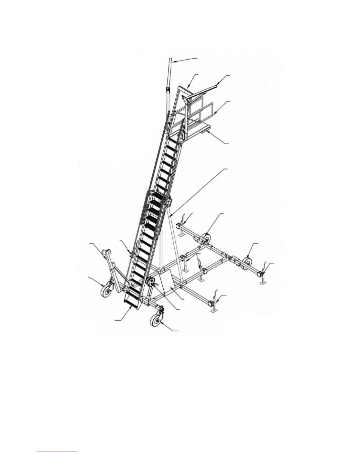
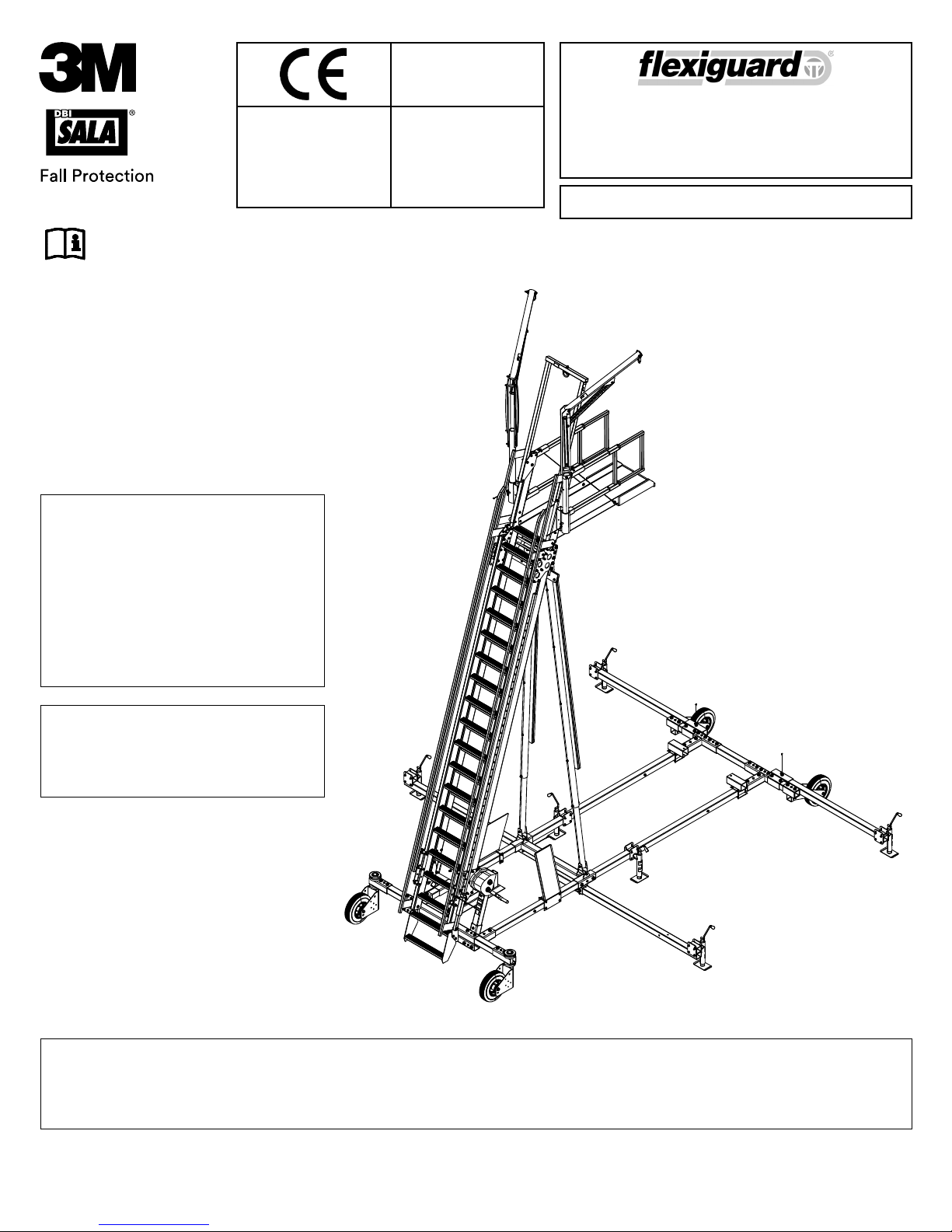
2.0 Ladder System Component Identifi cation
12
10
5
12
9
8
11
3
Back
7
4
3
2
Front
14
1. Jack
2. Swivel Wheel
3. Fixed Wheel
4. Outrigger (long)
5. Outrigger
6. Winch Post
7. Lifting Kit
8. Platform
1
5
13
6
2
9. Handrail (2)
10. Overhead Anchor Point Post
11. Ladder Support Tubes
12. Davit
13. Operators Setup and Use
Decal Plate
14. Step
4
3
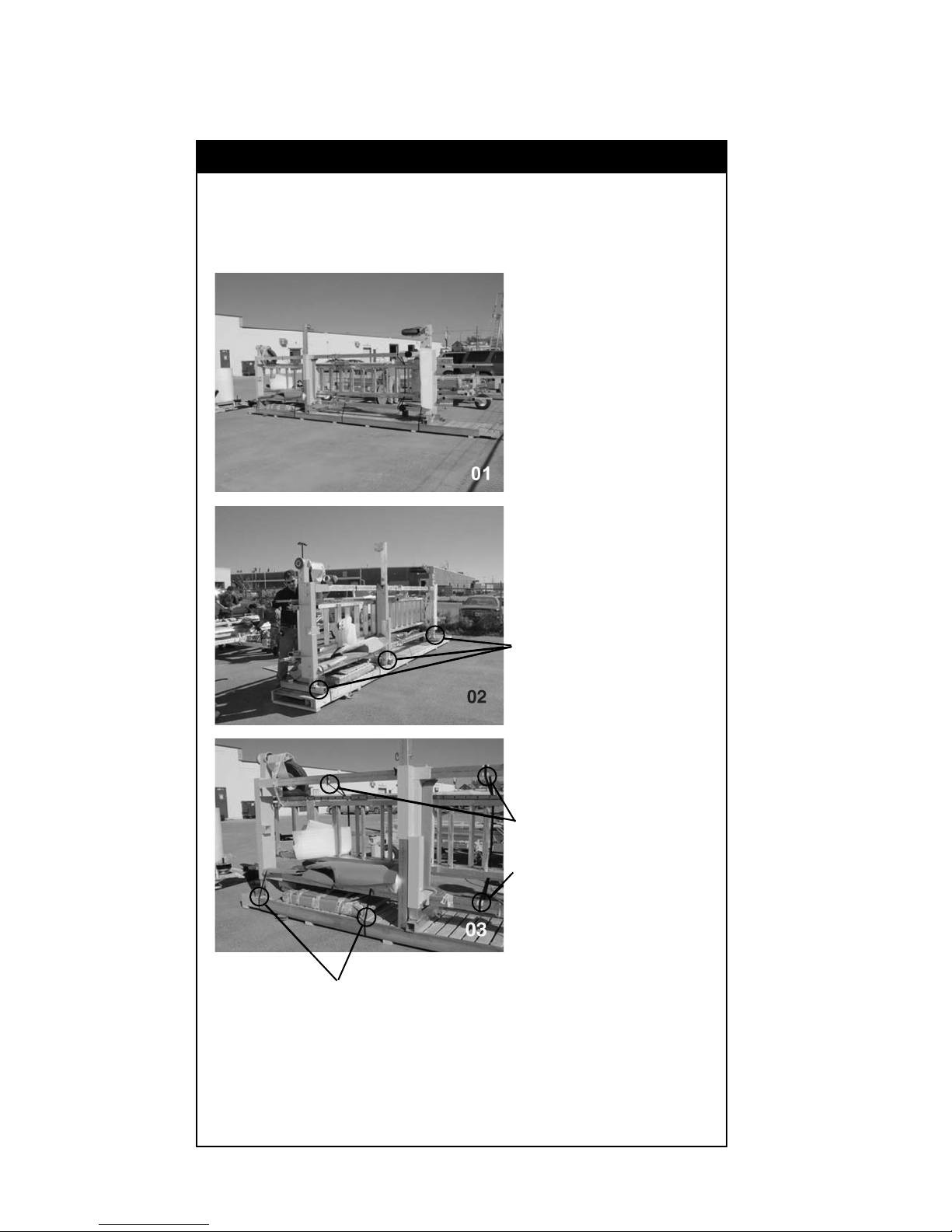
3.0 Ladder System Assembly
Figure 1 - Shipping Layout
The unit comes shipped on its side to keep the majority
of the unit assembled. Remove all loose packages and
place them out of the way at this stage of assembly.
Remove the strapping
holding the ladder to the
shipping pallet.
Aluminum shipping
stands.
The strap that is
secured from the
base to ladder
should stay secured
until the unit is
rested on the
ground.
4

3.0 Ladder System Assembly - Continued
Figure 2 - Remove from Pallet
After packages are removed, the base and ladder
assembly must be removed from the pallet.
Remove screws
and nails from the
aluminum stands to
separate the unit from
the pallet.
Place forklift under the
base as shown here.
Cut all strapping. Lift unit slowly to make certain it is
balanced on the forks. Reposition forks if necessary.
After the unit is off the pallet, slowly lower the unit to
the ground. Then, using the forklift, slowly back up while
rotating the unit fl at to the ground.
Using a 3/4”
wrench, loosen
all bolts that
secure the three
aluminum stands.
5
3.0 Ladder System Assembly - Continued
Figure 3 - Position for Assembly
Using the forklift,
lift the unit up to
assemble all four
wheels to the base.
Shipping stand.
Remove the center
aluminum shipping
stand.
6
3.0 Ladder System Assembly - Continued
Figure 3 Continued - Position for Assembly
Remove the front
aluminum shipping
stand.
Remove detent pins.
Rotate the middle
jacks down to help
support the base
while assembling the
wheels and outriggers
in the following steps.
Replace detent pins.
7
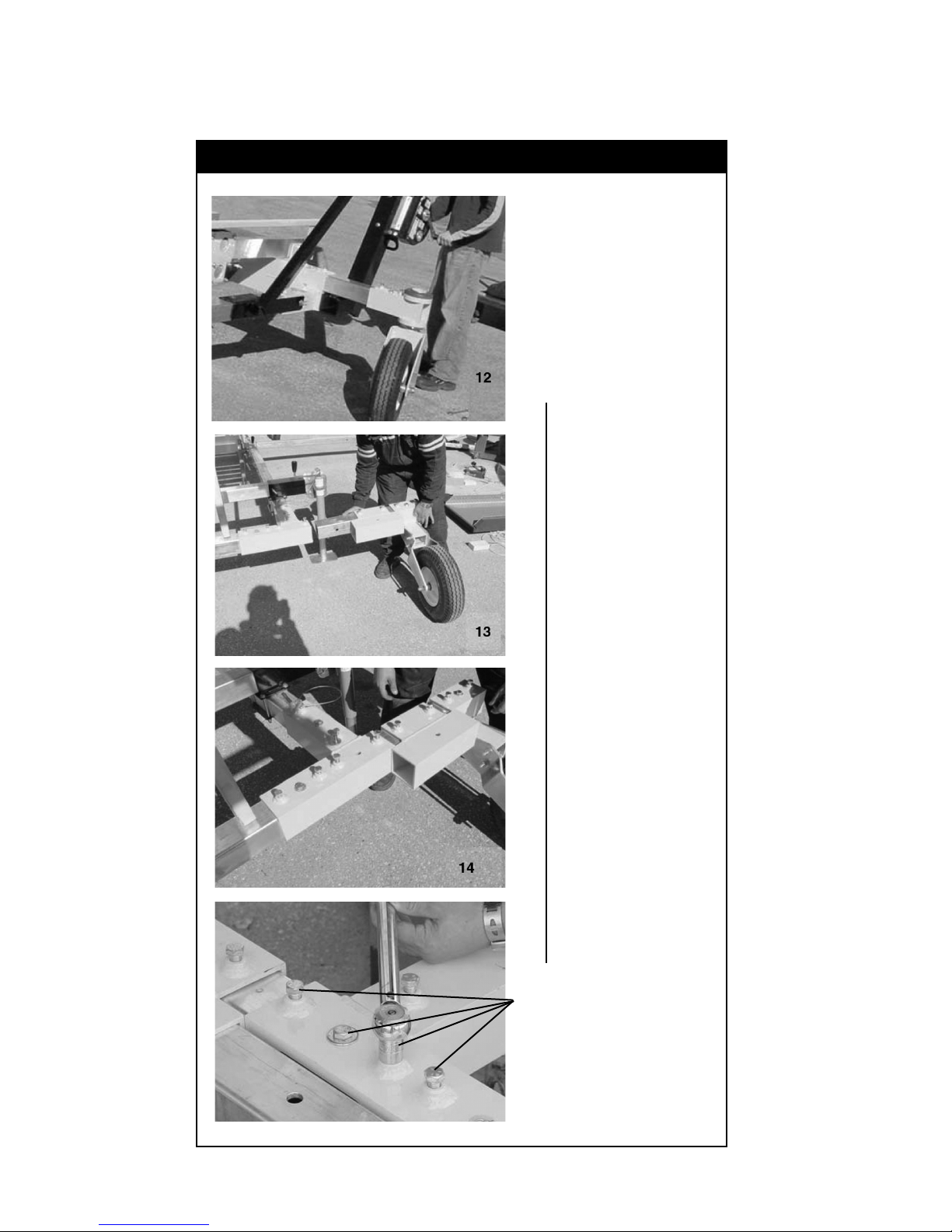
3.0 Ladder System Assembly - Continued
Figure 4 - Add Wheels
Add all four wheels
to the base. Swivel
casters are used
at the front. Fixed
casters are used at
the back.
Secure all bolts to
25 ft lbs (33.9 N.m).
Secure all bolts to
25 ft lbs (33.9 N.m).
8
3.0 Ladder System Assembly - Continued
Figure 5 - Insert Outriggers
Insert all outriggers
into their appropriate
sockets.
Longer outriggers are
used with the center
base section.
Orient jacks toward
fi xed wheels (back).
Make sure all detent
pins are fully inserted
and secure.
9
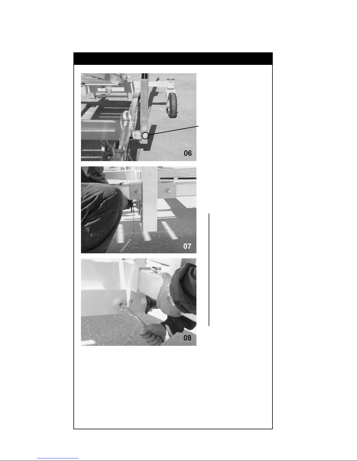
3.0 Ladder System Assembly - Continued
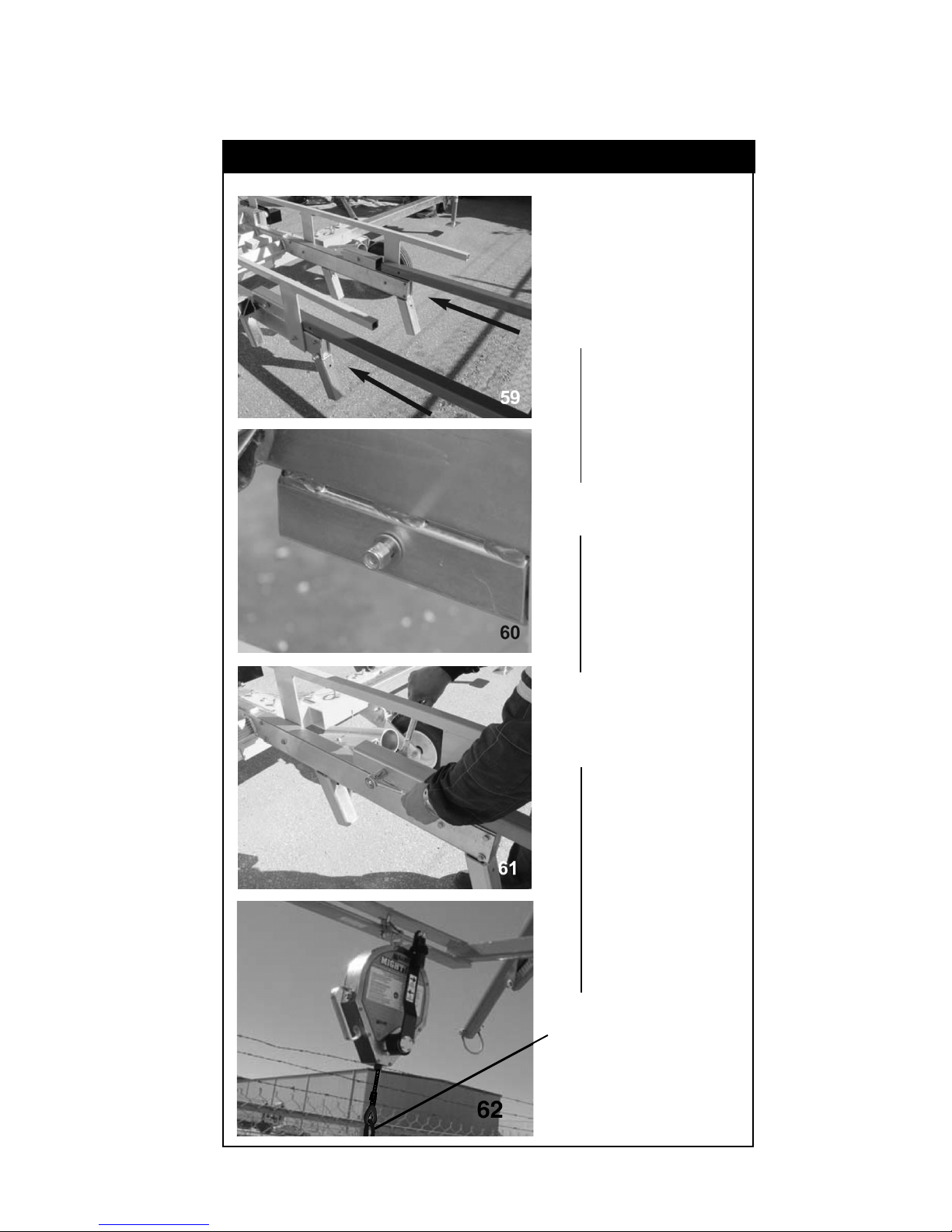
Figure 6 - Add Ladder Winch
Add the ladder
winch to the socket
on the right side of
the ladder.
Bolt the winch post
so it is at its tallest
position.
10
3.0 Ladder System Assembly - Continued
Figure 6 Continued - Add Ladder Winch
Unwind the cable,
leaving only 3 to 5
wraps.
Secure the handle
in operating
position with
detent pin.
11
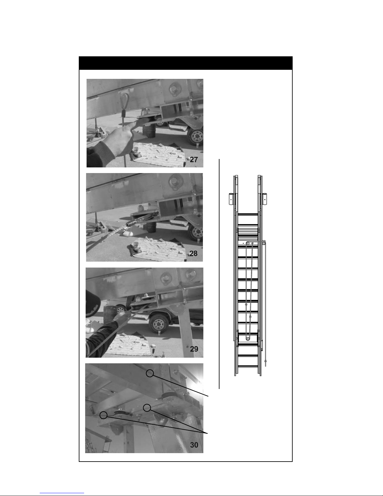
3.0 Ladder System Assembly - Continued
Figure 6 Continued - Add Ladder Winch
Feed the cable
through the fi rst
pulley as shown
here. Next, feed
the cable across
to the next pulley
and feed it through
as shown.
Cable
Cable
12
3.0 Ladder System Assembly - Continued
Figure 6 Continued - Add Ladder Winch
Feed the cable down
the pulley at the
bottom of the ladder
and back through the
other side as shown.
13

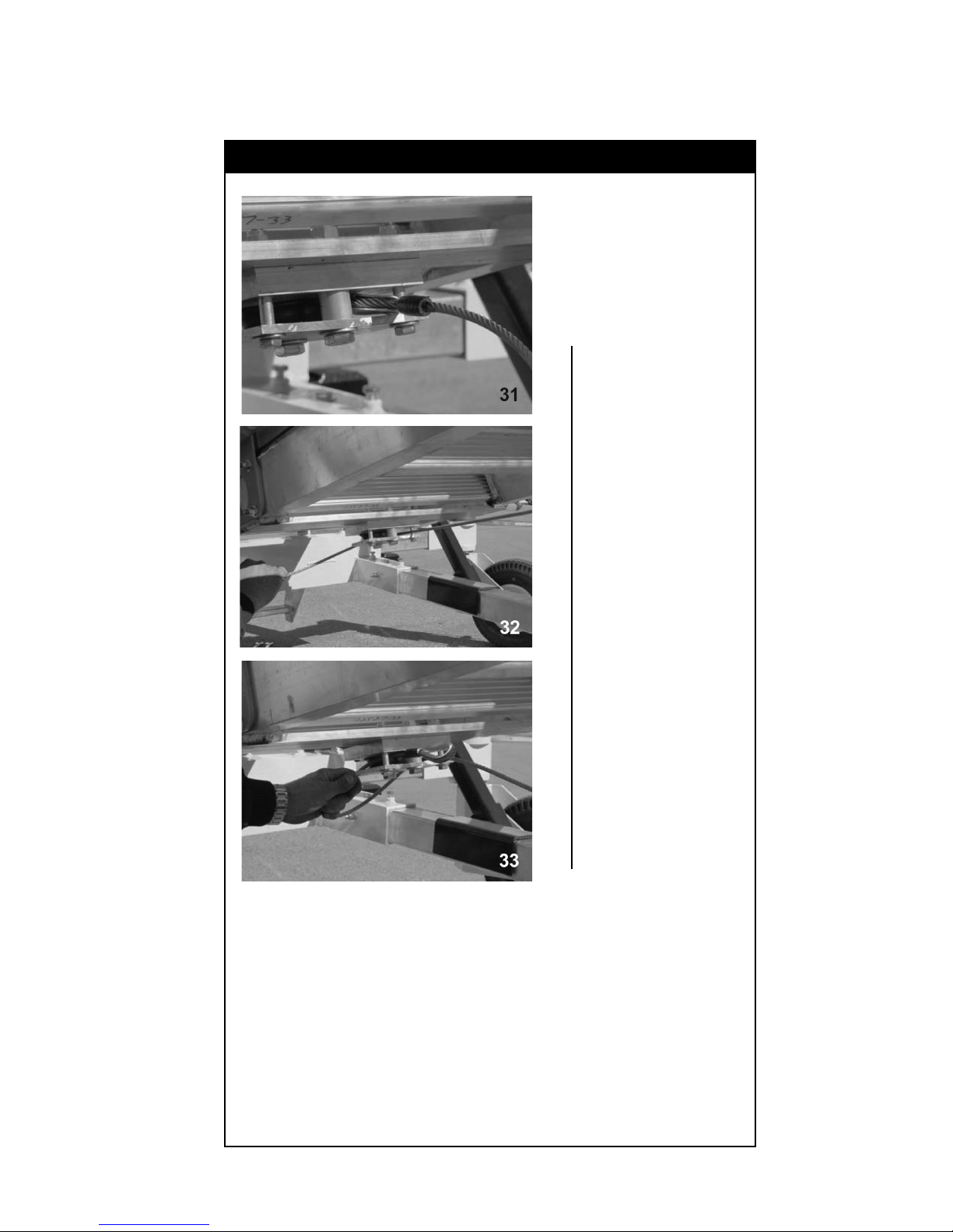
3.0 Ladder System Assembly - Continued
Figure 6 Continued - Add Ladder Winch
Next, pull the cable
back up to pulleys at
the top of the ladder
and attach to the bolt
located between the
two pulleys as shown
in illustrations 34 - 36.
Mounting
bolt
Nut
Washer
Washer
Cable Thimble
Washer
14
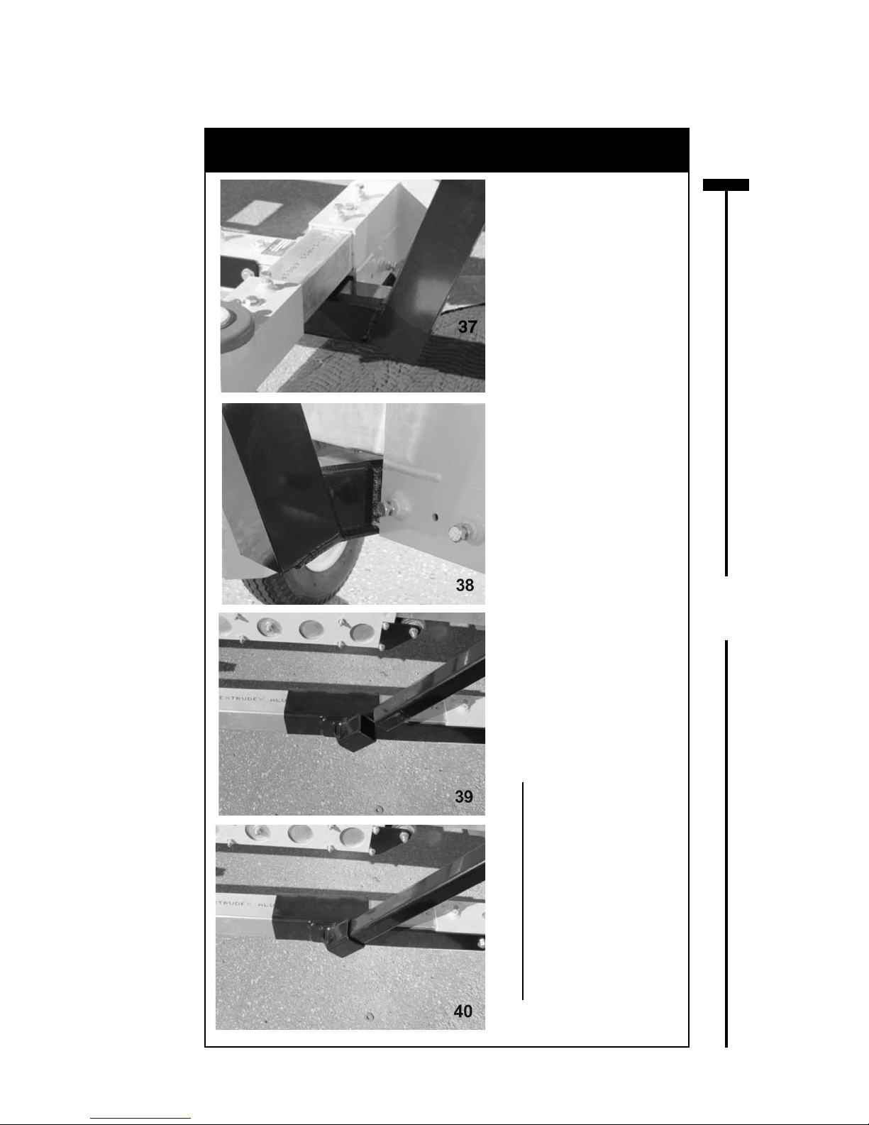
3.0 Ladder System Assembly - Continued
Figure 7 - Lifting Kit
(Skip this section if Lifting Kit was not ordered)
Skip this section if
no lifting kit was
ordered.
Substitute a crane or
forklift to erect the
ladder on the base.
WARNING
Do not stand under
the ladder while
assembling.
Add the lifting kit
to the base of the
ladder. First add the
post, making certain
it is angled away
from the unit. Tighten
the bolts to secure
the post as shown in
illustration 38.
Lift Kit
Section
15
Second, add the
support tube by
fi rst inserting it into
the receiver pocket
mounted on the
base, as shown in
39 and 40.
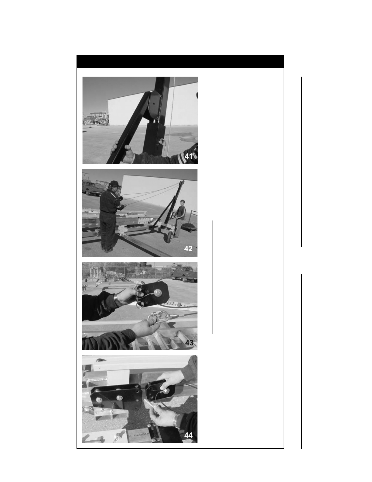
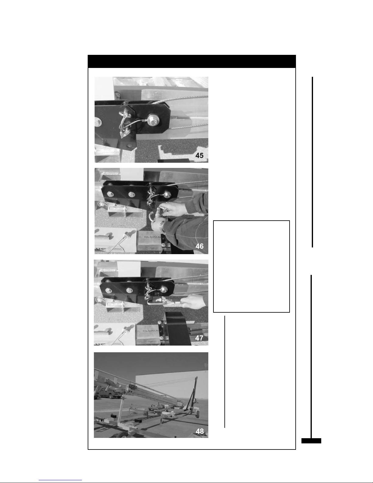
3.0 Ladder System Assembly - Continued
Figure 7 Continued - Lifting Kit
Third, bolt the
support tube
between the ears
located on the
lifting kit post as
shown in 41.
Unwind the cable
by holding both the
redirect pulley and
the carabiner as
shown in 42 and 43.
When the cable is
long enough, attach
both the redirect
pulley and the
carabiner to the
attachment at the
top of the ladder
as shown in 44
through 47.
Lift Kit
Section
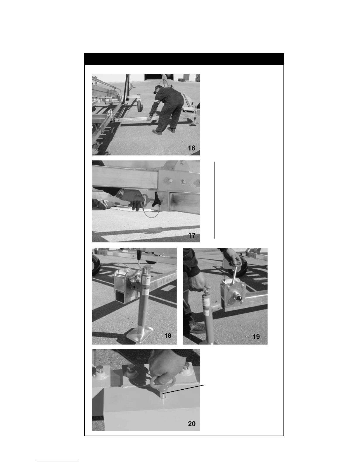
16
3.0 Ladder System Assembly - Continued
Figure 7 Continued - Lifting Kit
Before using the
lifting kit, ensure
that all connections
are secured. Unwind
the remaining cable
from the winch drum
and respool neatly to
avoid cable damage
sudden cable
jumping.
Do not raise the
ladder until the
ladder support tubes
are assembled (see
illustration 63).
WARNING
Once the ladder is
upright, secured and
ready to use, this
lifting device must
be disconnected
(remove carabiner)
to ensure that no
improper use occurs
while operating the
ladder.
Lift Kit
Section
End of Lift Kit
section.
17
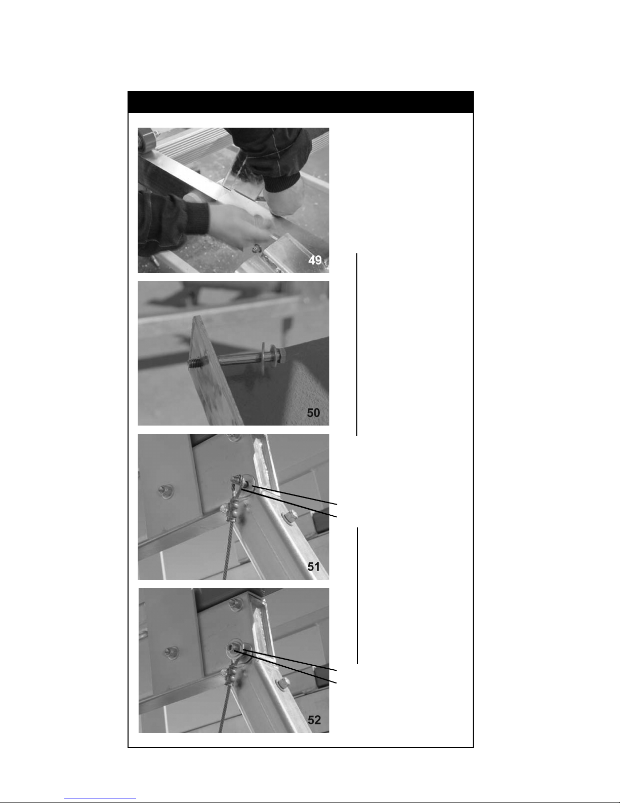
3.0 Ladder System Assembly - Continued
Figure 8 - Attach Platform to Ladder
Assemble the
platform to the
ladder. Remove the
nuts and washers
from both bolts
where the platform
mounts and the
cables attach.
Attach cables to
both sides.
Assemble hardware.
Washer
Cable
Washer
Nut
18
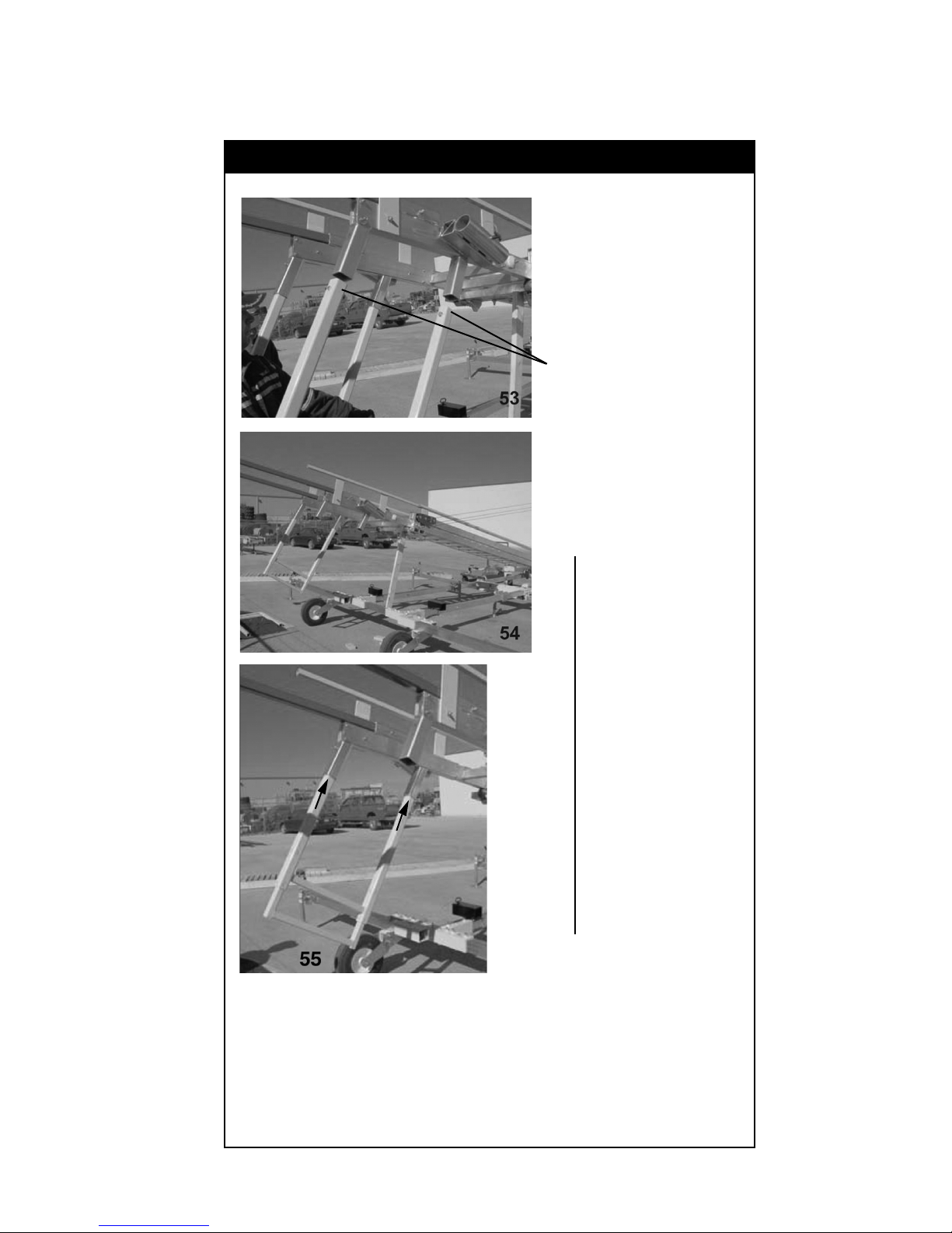
3.0 Ladder System Assembly - Continued
Figure 9 - Assemble Handrails
Assemble the
adjustable handrails
to the unit.
Insert the hand rails
to the steel sleeve
section handrail
pockets as shown in
54 and 55.
19
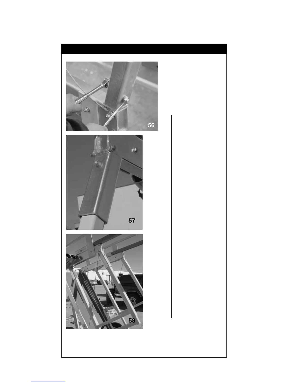
3.0 Ladder System Assembly - Continued
Figure 9 Continued - Assemble Handrails
Add bolts to secure
the handrails. Make
certain the cables
inside the tubing are
also secured by the
bolts by going through
the cable eyes.
20
3.0 Ladder System Assembly - Continued
Figure 10 - Assemble Overhead Anchor Post
Assemble the
overhead anchor
point post by
inserting the post into
the pockets on the
steel sleeve section.
Align holes and
bolt into place.
Attach an SRL that
will secure the
operator climbing up
and down the ladder.
Make certain a
tag line is
attached to pull
the retractable
cable down the
ladder before
climbing the unit.
21
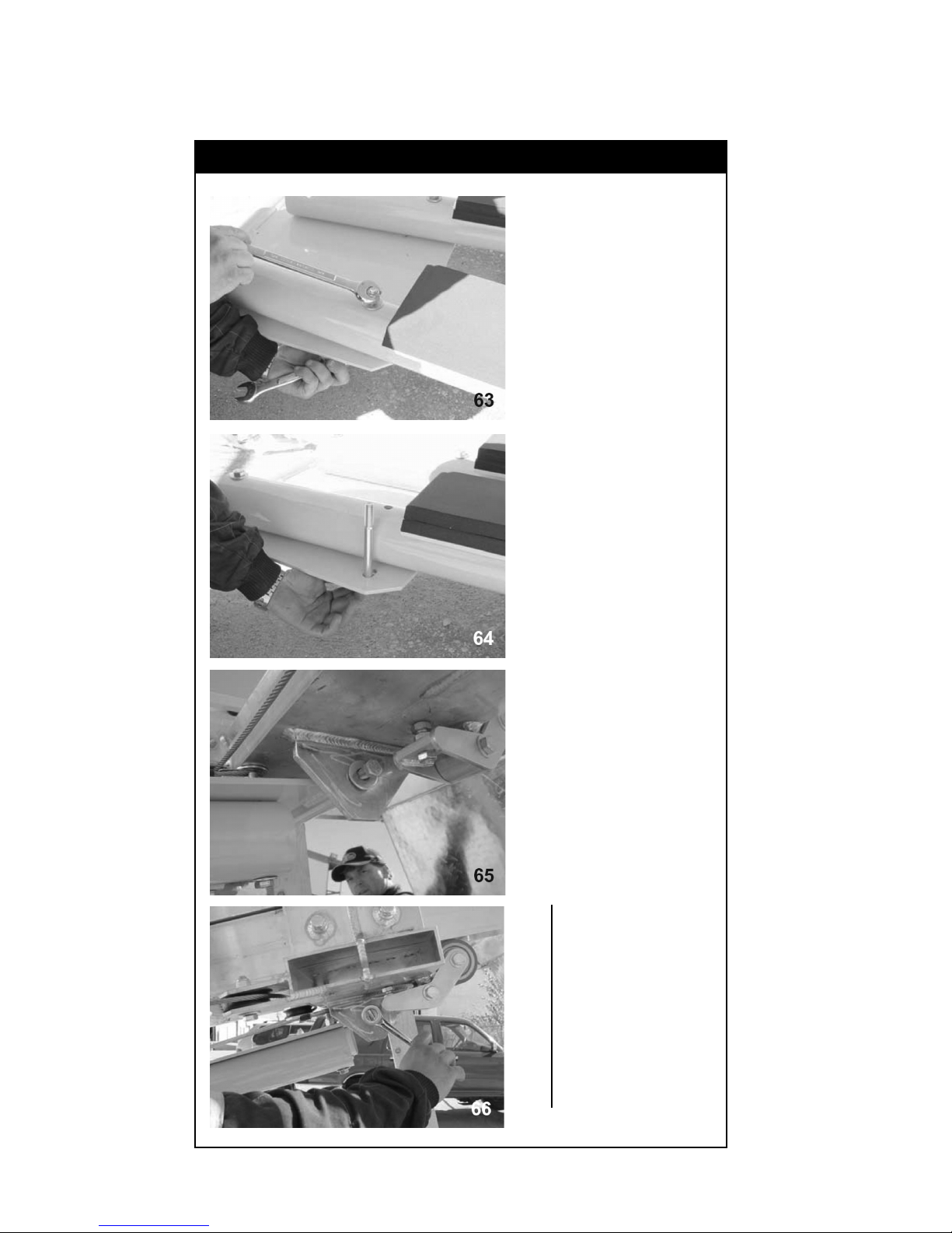
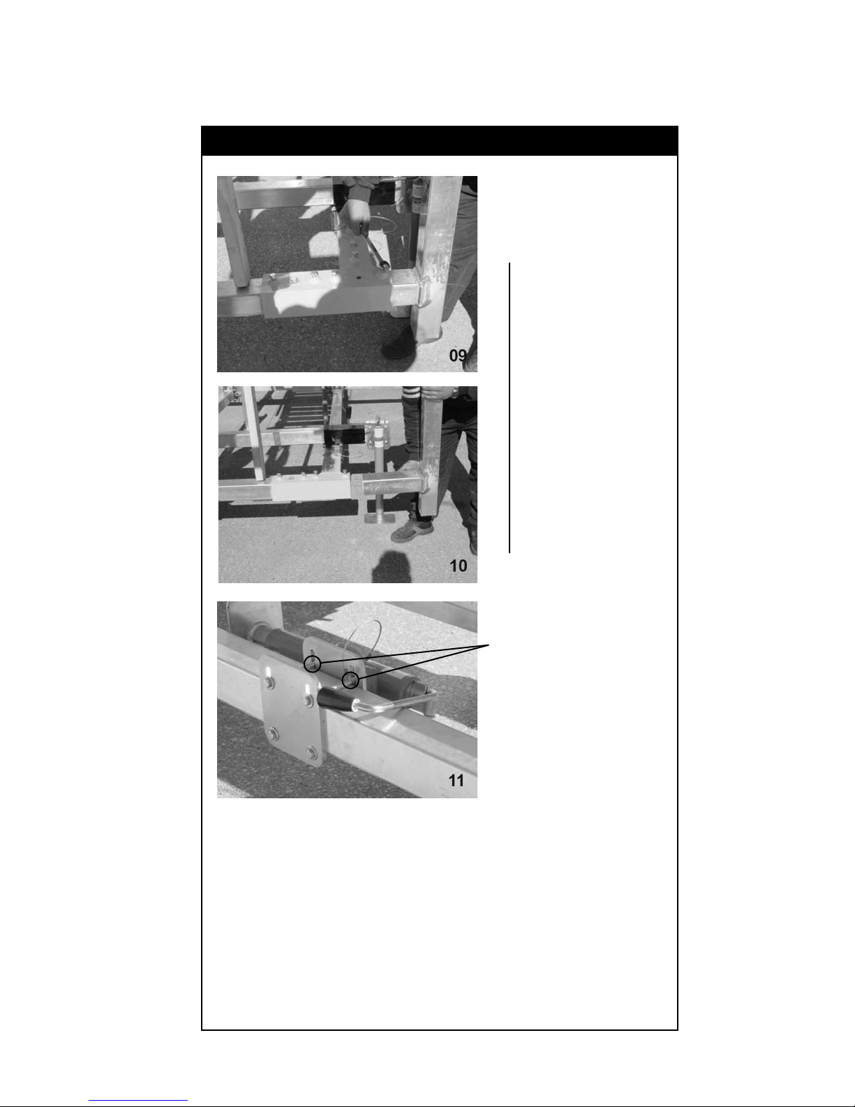
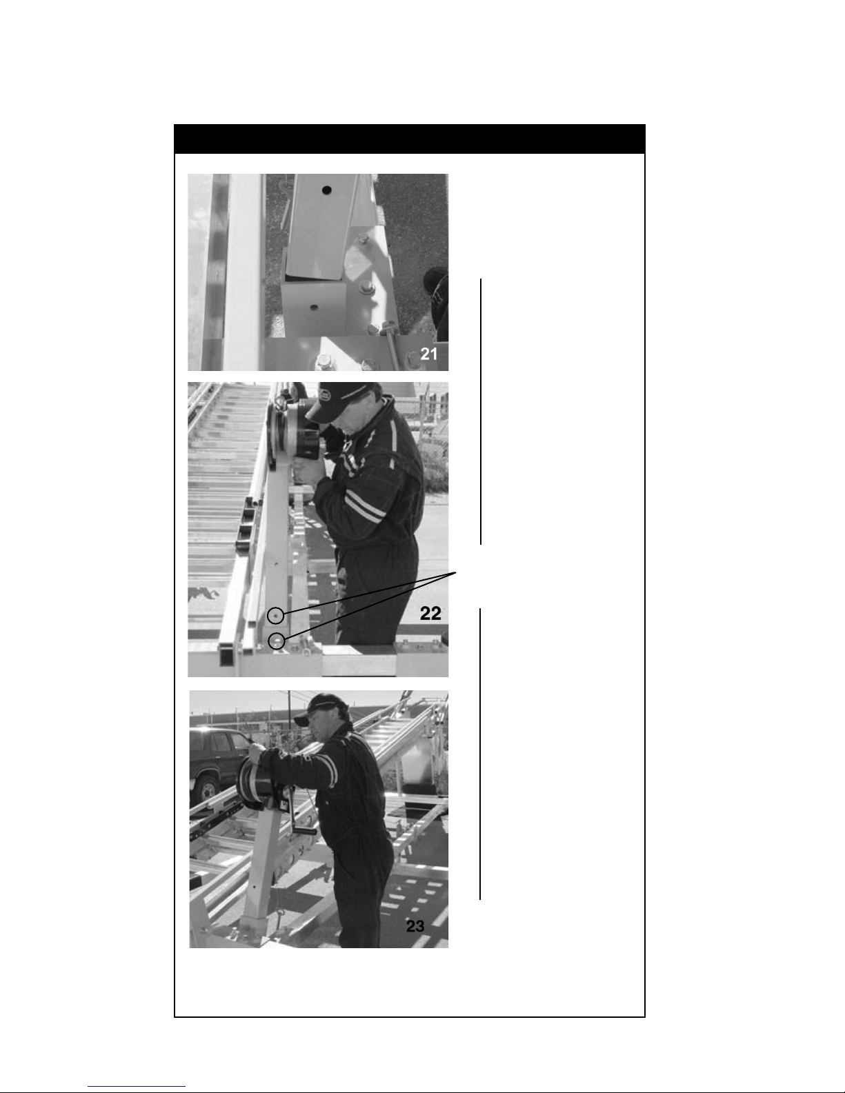
3.0 Ladder System Assembly - Continued
Figure 11 - Assemble Ladder Support Tubes
Assemble the ladder
support tubes.
Mount the support
tube assembly to the
ladder unit:
First, raise the ladder
using the lifting
device by about 4 to
5 feet.
Second, remove the
inner tubes from the
support tubes to be
able to align the holes
in the ears.
22
Third, slide the
support tube
assembly under the
raised ladder while
aligning the threaded
holes with the holes
in the ears under the
ladder, as shown in
65 and 66.

3.0 Ladder System Assembly - Continued
Figure 11 Continued - Assemble Ladder Support Tubes
Slowly lift the ladder
with attach support
tubes (using lift kit,
forklift or overhead
crane) until it is
possible to insert the
inner tubes of the
support tube assembly
and bolt into place.
23
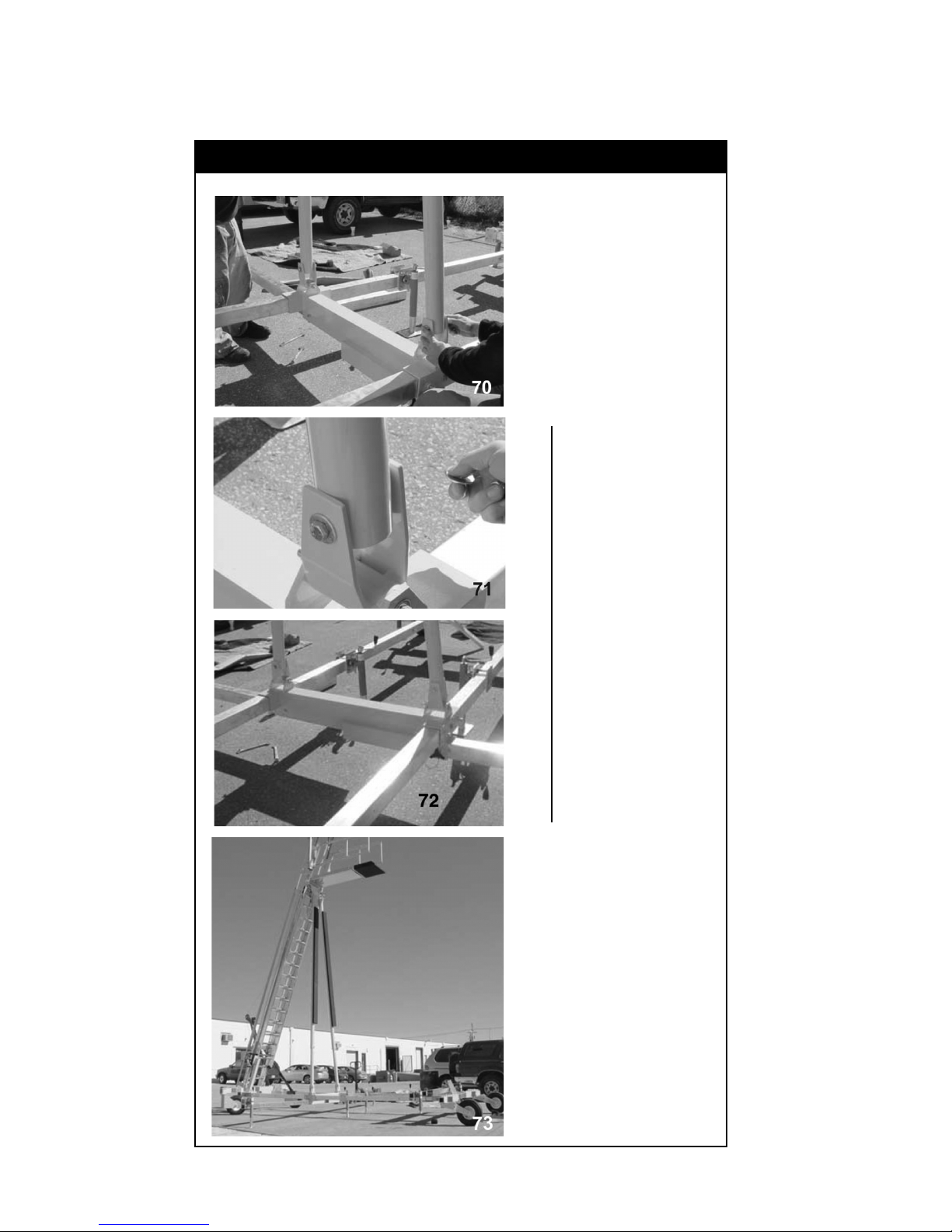
3.0 Ladder System Assembly - Continued
Figure 11 Continued - Assemble Ladder Support Tubes
Continue to lift
the ladder into its
operating position.
Mount the support
tubes into the U
channels attached
to the center
section of the base,
as shown in 70
through 72.
24
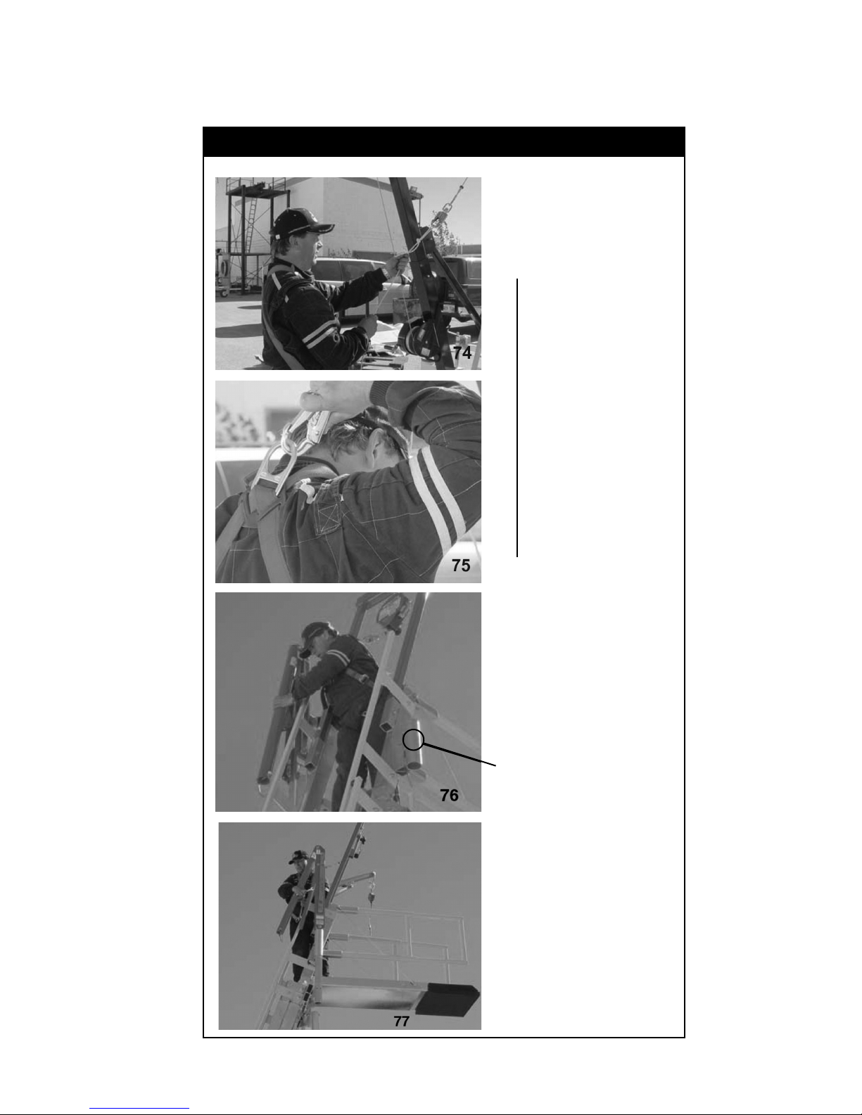
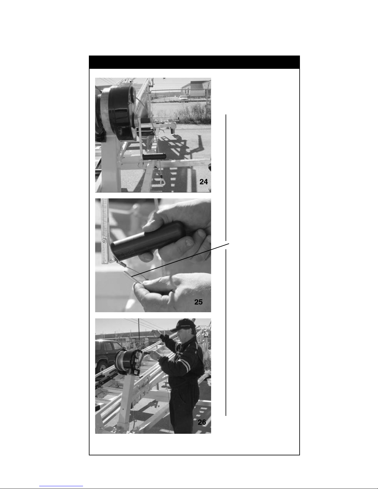
3.0 Ladder System Assembly - Continued
Figure 12 - Final Assembly Steps
Pull your tag line down
to attach the SRL
to your harness, as
shown in 74 and 75.
Depending on
available equipment,
you may want to use
a forklift or crane to
lift the davits up to
the steel sleeve and
insert them.
Sleeve
25
3.0 Ladder System Assembly - Continued
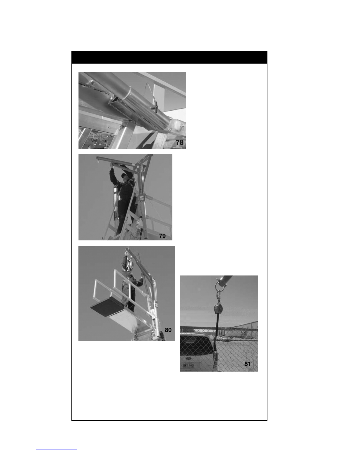
Figure 12 Continued - Final Assembly Steps
Next, pin the davits
into place as shown
in 78. Set up the
davits by removing
the hardware at the
end of the gusset and
attach the gusset to
the davit.
The davits will point
out and away from
the ladder. This gives
the operators a larger
working area with
approximately a 6
foot (1.8 m) radius.
(See User Instruction
Manual.)
Attach your SRLs,
not provided, to the
anchor point at the
end of each davit, as
shown in 79
through 81.
26
3.0 Ladder System Assembly - Continued
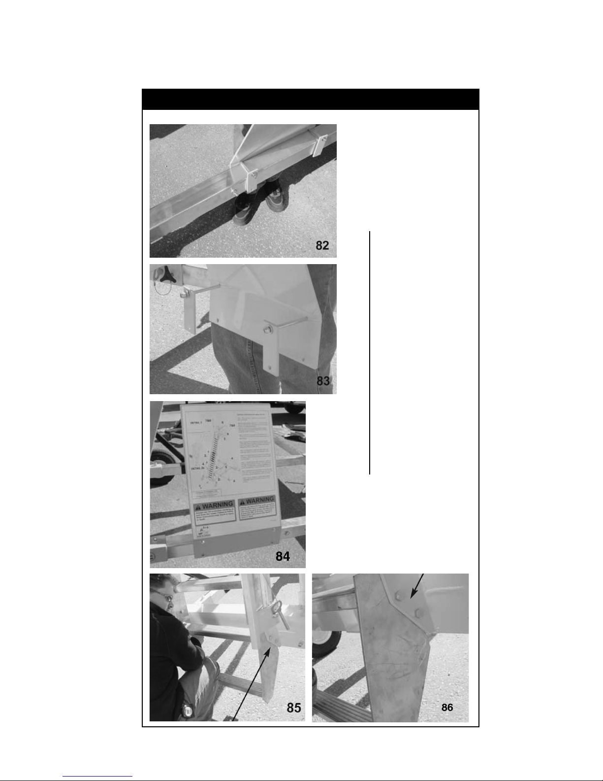
Figure 12 Continued - Final Assembly Steps
Attach the operators
setup and use decal
plate on the base of
the unit, as shown.
This should be on
the same side as
the winch.
27
Last, assemble the
step to the base of
the ladder. Assemble
the step between the
ears shown in 85.
Align and bolt.

4.0 Ladder System Maintenance and Inspection
4.1 Visual inspection after assembly
A complete visual inspection should be performed on the FPALS
equipment prior to operation. The following items should be checked;
and the results recorded on the “Maintenance and Inspection Log”
sheet found in the Operators Manual.
4.1 Labels
Check that all labels are clean and legible. Clean the labels if any are
dirty using a mild soap and a damp cloth. Replace if any are illegible.
4.2 Fasteners
Check that all ladder screws and other fasteners are tight. Tighten
ladder fasteners hand tight only. Base fasteners must be checked
using 15 ft. lbs (20.3 N.m) of torque. If any are loose, tighten to 20
ft. lbs (27.1 N.m).
Contact your local dealer or DBI-SALA for any replacement fasteners
that may be required
Check the components for cracks, dents, bends, or breaks.
Minor cosmetic damage in the component body will not affect the
function of the FPALS System. However, if there are major dents or
any other structural damage, the unit should not be used and should
be returned to the manufacturer for service.
28

Essai de type CE
N° 0086
BSI Product Services
B.P. 6221, Kitemark Court
Davy Avenue
Milton Keynes
MK1 9EP Royaume-Uni
L’utilisateur doit lire et comprendre ces instructions
avant d’assembler ou d’utiliser ce matériel.
IMPORTANT : ce manuel
d’instructions concerne uniquement
l’assemblage du produit. Le « manuel
d’instructions de l’utilisateur du
dispositif d'échelle antichute »
(5902345) décrit l’utilisation, le
fonctionnement et l’entretien de ce
produit. Il incombe à l’employeur de
remettre le manuel d’instructions
de l’utilisateur à tout utilisateur de
l’équipement ou sauveteur.
EN795: 1996
Classe B
Contrôle qualité
production CE
N° 0086
BSI Product Services
B.P. 6221, Kitemark Court
Davy Avenue
Milton Keynes
MK1 9EP Royaume-Uni
Dispositif d'échelle antichute
Numéros de modèles :
8517714
8517715
8517716
8517717
8517718
8517719
8530140
8560010
Instructions d’assemblage
IMPORTANT : pour toute question
relative à l’utilisation, l’entretien ou
la compatibilité de cet équipement de
sécurité à une utilisation particulière,
adressez-vous à Capital Safety.
IMPORTANT : ces instructions d’assemblage doivent être mises à la disposition de la personne chargée d’assembler
l’équipement. Celle-ci doit lire et comprendre ces instructions du fabricant avant de commencer la procédure
d’assemblage. Elle doit respecter les instructions relatives à chaque composant du système. Toute modifi cation ou
utilisation inappropriée de ce produit, ou le non-respect de ces instructions d’assemblage, peut provoquer des blessures
graves voire la mort.
Nº DE FORMULAIRE : 5902369
RÉV. : C
© Copyright 2013, Capital Safety
 Loading...