

Page 1

Instructions and Parts List
Important Safety
Information
™
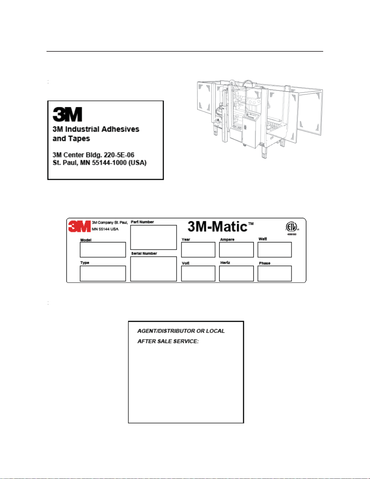
3M-Matic
800rf Type 40800
Random
Case Sealer
with
BEFORE INSTALLING
OR OPERATING THIS
EQUIPMENT
Read, understand, and
follow all safety and
operating instructions.
Spare Parts
™
AccuGlide 3
Taping Heads
Serial No.
For reference, record machine serial number here.
3M Industrial Adhesives and Tapes
3M Center, Building 220-5E-06
St. Paul, MN 55144-1000
It is recommended you
immediately order the
spare parts listed in the
"Spare Parts/Service
Information" section.
These parts are expected
to wear through normal
use, and should be kept
on hand to minimize
production delays.
"3M-Matic"and "AccuGlide" are Trademarks of,
3M St. Paul, MN 55144-1000
Printed in U.S.A.
© 3M 2012 44-0009-2085-8 (B030912-NA)
Page 2

This instruction manual covers safety aspects,
handling and transport, storage, unpacking,
preparation, installation, operation, adjustments, maintenance, troubleshooting, repair
work and servicing plus parts list of the
3M-Matic 800rf Random case sealer.
3M Industrial Adhesives and Tapes
3M Center, Building 220-5E-06
St. Paul, MN 55144-1000
Edition March 2012
Copyright 3M 2012
All rights reserved
The manufacturer reserves the right to change
the product at any time without notice.
800rf-NA
2012 March
Page 3

Replacement Parts and Service Information
To Our Customers:
This is the 3M-Matic™/AccuGlide™/Scotch
®
equipment you ordered. It has been set up and tested in
the factory with Scotch® tapes. If technical assistance or replacement parts are needed, call or fax the
appropriate number listed below.
Included with each machine is an Instructions and Parts List manual.
Technical Assistance / Replacement Parts and Additional Manuals:
Contact your local service provider. Provide the customer support coordinator with the model/
machine name, machine type, and serial number that are located on the identifi cation plate -
(For example: Model 800rf - Type 40800 - Serial Number 13282).
Replacement Parts and Additional Manuals
Order parts by part number, part description, and quantity required.
When ordering parts or additional manuals, include model/machine name,
machine type, and serial number that are located on the identifi cation plate
(For example: Model 800rf - Type 40800 - Serial Number 13282).
3M Industrial Adhesives and Tapes
3M Center, Building 220-5E-06
St. Paul, MN 55144-1000
Identifi cation Plate
For Commercial Use Only
3M-Matic™, AccuGlide™ and Scotch™
are Trademarks of
3M St. Paul, MN 55144-1000
Printed in U.S.A.
i
Page 4

THIS PAGE IS BLANK
Page 5

Replacement Parts And Service Information
To Our Customers:
This is the 3M-Matic™/AccuGlide™/Scotch® equipment you ordered. It has been set up
and tested in the factory with Scotch® tapes. If any problems occur when operating this equipment and
you desire a service call or phone consultation, call, write, or fax the appropriate number listed below.
Included with each machine is an Instructions and Parts List manual.
SERVICE, REPLACEMENT PARTS, AND ADDITIONAL MANUALS
AVAILABLE DIRECT FROM:
Order parts by part number, part description, and quantity required. Also, when ordering parts
or additional manuals, include model/machine name, machine type, and serial number that are
located on the identifi cation plate.
3M Industrial Adhesives and Tapes
3M Center, Building 220-5E-06
St. Paul, MN 55144-1000
ii
3M-Matic™, AccuGlide™ and Scotch
are Trademarks of
3M, St. Paul, MN 55144-1000
Printed in U.S.A.
™
Page 6

THIS PAGE IS BLANK
Page 7

TABLE OF CONTENTS - MANUAL 1: 800rf Random Case Sealer
(For Taping Head Information - See MANUAL 2: AccuGlide 3 Taping Heads - 2 Inch)
800rf Random Case Sealer Page
Cover Page
Replacement Parts and Service Information ........................................................................ i - ii
Table of Contents ................................................................................................................. iii - v
Acronyms and Abbreviations ................................................................................................ vi
1. Introduction
1.1 Manufacturing Specifi cations / Description / Intended Use
1.2 How to Read and Use the Manual ................................................................................ 2
1.2.1 Importance of the Manual .................................................................................. 2
1.2.2 Manual Maintenance ......................................................................................... 2
1.2.3 Consulting the Manual ........................................................................................ 2
1.2.4 How to Update the Manual in Case of Modifi cations ........................................... 2
2. General Information
2.1 Identifi cation Data ......................................................................................................... 3
2.2 After-Sale Service ......................................................................................................... 3
2.3 Warranty / Contents ...................................................................................................... 4
3. Safety
3.1 General Safety Information ........................................................................................... 5
3.2 Signal Words Explanation ............................................................................................. 5
3.3 Table of Warnings .......................................................................................................... 6 - 7
3.4 Operator’s Qualifi cations Defi nition .............................................................................. 8
3.5 Number of Operators .................................................................................................... 8
3.6 Safe Use of the Machine Instructions ........................................................................... 8
3.7 Residual Hazards .......................................................................................................... 8
3.8 Prevent Other Hazards - Recommendations and Measures ........................................ 8
3.9 Personal Safety Measures ........................................................................................... 8
3.10 Incorrect / Predictable Actions Not Allowed .................................................................. 8
3.11 Operator's Required Skill Levels .................................................................................. 9
3.12 Component Locations .................................................................................................. 10
3.13 Table of Warnings and Replacement Labels ................................................................ 11
......................................... 1 - 2
4. Technical Specifi cations
4.1 Power Requirements .................................................................................................... 12
4.2 Operating Rate
4.3 Operating Conditions .................................................................................................... 12
4.4 Tape .............................................................................................................................. 12
4.5 Tape Width .................................................................................................................... 12
4.6 Tape Roll Diameter ....................................................................................................... 13
4.7 Tape Application Leg Length - Standard .......................................................................13
Tape Application Leg Length - Optional
4.8 Box Board ..................................................................................................................... 13
4.9 Box Weight and Size Capacities ................................................................................... 13
4.10 Machine Noise Levels ................................................................................................... 14
4.11 Machine Dimensions / Power Requirements ................................................................. 14
4.12 Set-Up Recommendations ............................................................................................ 14
800rf-NA
............................................................................................................. 12
iii
2012 March
Page 8

THIS PAGE IS BLANK
8
Page 9

TABLE OF CONTENTS (continued)
5. Shipment, Handling, and Storage
5.1 Packed Machine Shipment and Handling .......................................................................... 15
5.2 Overseas Shipment Packaging (Optional) ......................................................................... 15
5.3 Handling and Transportation of Uncrated Machine ............................................................ 15
5.4 Machine Storage ................................................................................................................ 15
6. Unpacking
6.1 Uncrating ............................................................................................................................ 16
6.2 Packaging Materials Disposal ............................................................................................ 16
7. Installation
7.1 Operating Conditions ......................................................................................................... 17
7.2 Space Requirements for Machine Operation and Maintenance ........................................ 17
7.3 Tool Kit / Parts Supplied with the Machine ......................................................................... 17
7.4 Machine Positioning / Bed Height ...................................................................................... 17
7.5 Plastic Ties Removal .......................................................................................................... 18
7.6 Assembly Completion / Machine Set-Up ............................................................................. 18 - 21
7.7 Preliminary Electric Inspection ............................................................................................ 22
7.8 Phases Inspection (for 3 phase).......................................................................................... 22
7.9 Completion of Taping Head ..................................................................................................23
8. Controls
8.1 Control Board .................................................................................................................... 24
9. Operation
9.1 Operation ........................................................................................................................... 25 - 27
9.2 Operation Methods .............................................................................................................. 27
9.3 Stop Methods ...................................................................................................................... 27
9.4 Alarms ................................................................................................................................ 28
10. Safety devices
10.1 Blade Guards .................................................................................................................... 29
10.2 Emergency Stop Button / Stop Switches ........................................................................... 29
10.3 Stop Switches ................................................................................................................... 29
10.4 Electric System ................................................................................................................. 29
11. Set-Up and Adjustments
11.1 Tape Loading on the Top Unit ........................................................................................... 30
11.2 Tape Loading on the Bottom Unit ...................................................................................... 31
11.3 Tope Drum Alignment ...................................................................................................... 31
11.4 Tape Drum Friction Brake Adjustment.................................................................................31
11.5 Adjustment of Taping Units According to the Type of Boxes............................................... 31
11.6 Main Pressure Regulator .................................................................................................. 32
11.7 Centering Guides Pressure .............................................................................................. 32
11.8 Side Drives Pressure Adjustment ..................................................................................... 32
11.9 Box Height Pick-up ........................................................................................................... 33
11.10 Upper Unit Descent Pressure Regulator .......................................................................... 33
11.11 Pneumatic Speed Regulators ........................................................................................... 34
11.12 Speed Regulators of the Rear Flap Folder ....................................................................... 35
11.13 Adjustment of the Upper Unit Height ................................................................................ 35
11.14 Adjustment of the Sensor that Stops the Descent of the Upper Unit ................................. 36
11.15 Adjustments of the Side Compression Rollers ................................................................. 37
11.16 Adjustment of the Magnetic Limit Switch on the Side Drives Air Cylinder.......................... 37
11.17 Use and Adjustments of the Photocells ............................................................................ 38
800rf-NA
i
iv
2012 March
Page 10

THIS PAGE IS BLANK
Page 11

TABLE OF CONTENTS (continued)
12. Troubleshooting
12.1 Troubleshooting .............................................................................................................. 39 - 40
13. Maintenance
13.1 Safety Measures (see section 3) .................................................................................... 41
13.2 Tools and Spare Parts Supplied with Machine ................................................................ 41
13.3 Maintenance Operations - Recommended Inspections and Frequency .......................... 41
13.4 Inspections to be Performed Before and After Every Maintenance Operation ................ 41
13.5 Safety Features (Inspection Effi ciency) / Circuit Breaker.................................................. 41
13.6 Machine Cleaning ........................................................................................................... 41
13.7 Cutter Blade Cleaning ..................................................................................................... 41
13.8 Securities Check-up ......................................................................................................... 42
13.9 Machine Lubrication ........................................................................................................ 42
13.10 Lubrication Products ........................................................................................................ 42
13.11 Drive Belt Replacement .................................................................................................. 43 - 44
13.12 Box Drive Belt Tension ..................................................................................................... 45
13.13 Upper Assembly Descent Brake Adjustment ................................................................... 45
13.14 Maintenance Work Log ................................................................................................... 47
14. Additional Instructions
14.1 Machine Disposal Information ........................................................................................ 49
14.2 Fire emergency ............................................................................................................... 49
15. Enclosures and Special Information
15.1 Statement of Conformity ................................................................................................. 49
15.2 Hazardous Substances Emission ................................................................................... 49
16. Technical Documentation and Information
16.1 Electric Diagrams ............................................................................................................ 51 - 53
16.2 Pneumatic Diagrams ....................................................................................................... 54
16.3 Spare Parts / Ordering .................................................................................................... 55 - 57
Drawings and Parts Lists ....................................................................................................... 59 - End of Manual
TAPING HEAD INFORMATION -
MANUAL 2: AccuGlide™ 3 Taping Heads - 2 Inch (See MANUAL 2 for Table of Contents)
800rf-NA
v
11
2012 March
Page 12

ABBREVIA TIONS AND ACRONYMS
LIST OF ABBREVIATIONS, ACRONYMS
3M-Matic - Trademark of 3M St. Paul, MN 55144- 1000
AccuGlide - Trademark of 3M St. Paul, MN 55144-1000
Scotch - Trademark of 3M St. Paul, MN 55144-1000
Drw. - drawing
Ex. - for example
Fig. - exploded view fi gure no. (spare parts)
Figure - Illustration
Max. - maximum
Min. - minimum
Nr. - number
N/A - not applicable
OFF - machine not operating
ON - machine operating
PLC - Programmable Logic Control
PP - Polypropylene
PU/PUFoam - Polyurethane Foam
PTFE - Polytetrafl ourethelene
PVC - Poly-vinyl chloride
W - Width
H - Height
L - Length
800rf-NA
vi
2012 March
Page 13
1-INTRODUCTION
1.1 Manufacturing Specifi cations / Description / Intended Use
The 3M-Matic™ Model 800rf Type 40800 Automatic Random Case Sealer with AccuGlide™ 3 Taping Heads is
designed to accept fi lled, regular slotted containers from an existing conveyor, fold the top fl aps, and apply a “C”
clip of Scotch™ brand Pressure-Sensitive Film Box Sealing Tape to the top and bottom center seams. Two sidedrive belt assemblies convey the cases through the machine.
The 800rf Case Sealer is to be used with infeed and exit conveyors supplied by the customer.
Do not attempt to run the case sealer without infeed and exit conveyors in place.
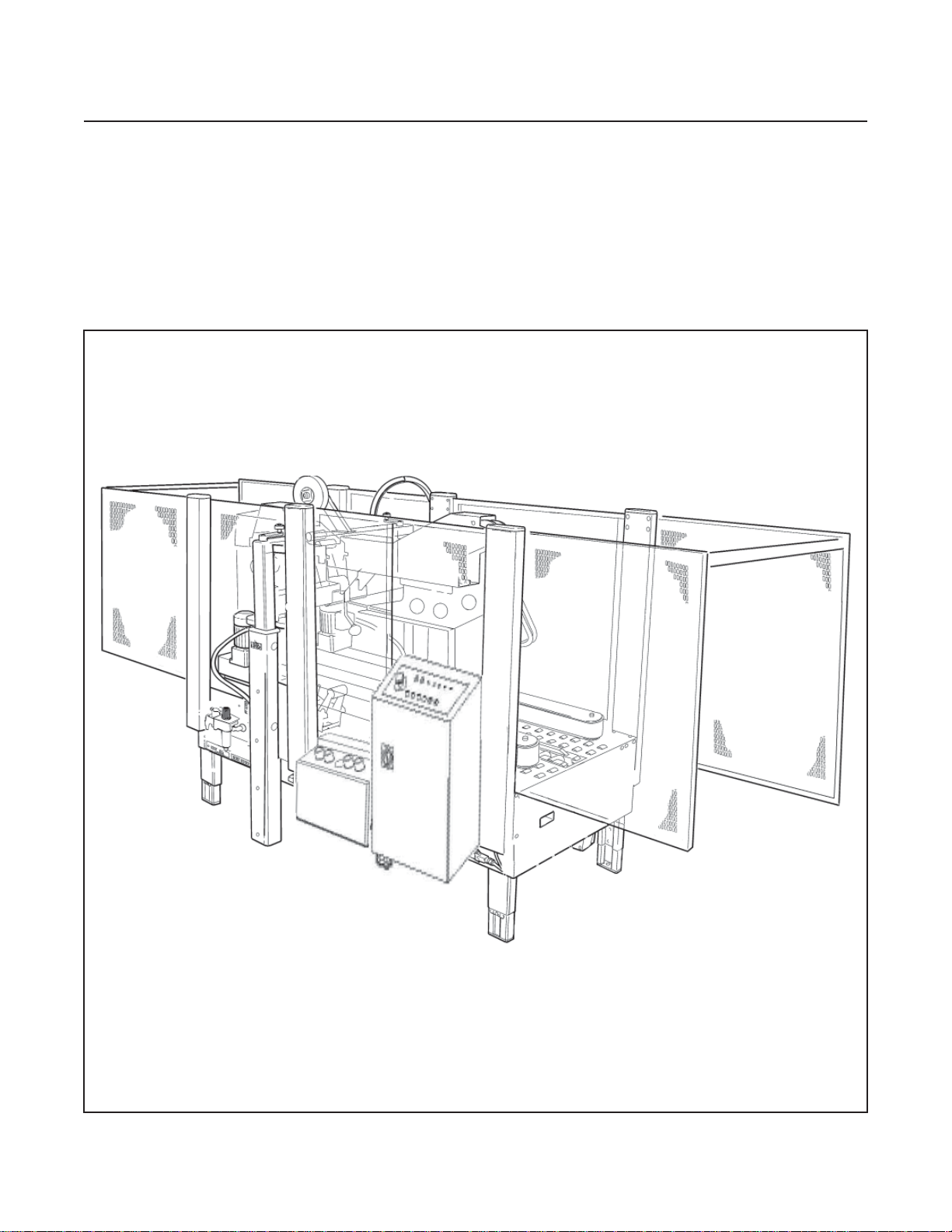
3M-MaticTM 800rf Random Case Sealer, Type 40800
800rf-NA
1
2012 March
Page 14
1-INTRODUCTION (continued)
1.1 Manufacturing Specifi cations / Description /
Intended Use (continued)
The 800rf Case Sealer is controlled from two operator
control panels located on the front left side of the case
sealer. These control panels (Electrical Control Panel
and Pneumatic Control Panel) have the most-used
controls within easy reach of the operator. The case
sealer is microprocessor-based and fi rmware con-
trolled to maintain maximum and precise control over
all operations within the case sealer.
The case sealer may be operated in Random, Fixed,
or Bypass mode. A selector switch is located on the
top of the Electrical Control Panel.
• In Random mode, the case sealer automatically adjusts itself for a wide range of case sizes,
providing a tape seal on the top and bottom of the
cartons. Random mode is considered the standard operating mode.
• In Fixed mode, the case sealer runs multiple
cartons of the same (fi xed) size, providing a tape
seal on the top and bottom of the cartons.
• In Bypass mode, the case sealer passes certain
containers through the machine, providing a tape
seal only on the bottom of the containers. The top
of these containers is not sealed.
1.2.1 Importance of the Manual
The manual is an important part of the machine; all
information contained herein is intended to enable
the equipment to be maintained in perfect condition
and operated safely. Ensure that the manual is available to all operators of this equipment and is kept
up to date with all subsequent amendments. Should
the equipment be sold or disposed of, please ensure
that the manual is passed on. Electrical and pneumatic diagrams are included in the manual. Equipment using PLC controls and/or electronic components will include relevant schematics or programs in
the enclosure and in addition, the relevant documentation will be delivered separately.
1.2.2 Manual Maintenance
Keep the manual in a clean and dry place near the
machine. Do not remove, tear, or rewrite parts of
the manual for any reason. Use the manual without
damaging it. In case the manual has been lost or
damaged, ask your after sale service for a new copy.
1.2.3 Consulting the Manual
CAUTION
• Never change operating modes
while a box is in the case sealer.
- Change modes only after a box
exits the case sealer and before
the next box enters the case sealer.
1.2 How to Read and Use the Instruction Manual
This instruction manual covers safety aspects, handling and transport, storage, unpacking, preparation,
installation, operation, set-up and adjustments, technical and manufacturing specifi cations, maintenance,
troubleshooting, repair work and servicing, electric
diagrams, warranty information, disposal (ELV), a
defi nition of symbols, plus a parts list of the 3M-Matic
800rf Random case sealer 3M Industrial Adhesives
and Tapes Division 3M Center, Bldg. 220-5E-06
St. Paul, MN 55144-1000 (USA) Edition March 2012
Copyright 3M 2012 All rights reserved. The manufacturer reserves the right to change the product at any
time without notice Publication © 3M 2012 44-0009-
2085-8.
The manual is composed of:
- Pages which identify the document and the machine
- Index of the subjects
- Instructions and notes on the machine
- Enclosures, drawings and diagrams
- Spare parts (last section)
All pages and diagrams are numbered. The spare
parts lists are identifi ed by the fi gure identifi cation
number. All the notes on safety measures or
possible dangers are identifi ed by the symbol:
1.2.4 How to Update the Manual in Case of
Modifi cations to the Machine
Modifi cations to the machine are subject to manu-
facturer’s internal procedures. The user receives a
complete and up-to-date copy of the manual together with the machine. Afterwards the user may
receive pages or parts of the manual which contain
amendments or improvements made after its fi rst
publication. The user must use them to update this
manual.
800rf-NA
2
2012 March
Page 15
2-GENERAL INFORMATION
2.1 Data Identifying Manufacturer and Machine
2.2 Data for Technical Assistance and Service
For Commercial Use Only
800rf-NA
3
2012 March
Page 16

2-GENERAL INFORMATION (continued)
2.3 Warranty
Equipment Warranty and Limited Remedy: THE FOLLOWING WARRANTY IS MADE IN LIEU OF ALL
OTHER WARRANTIES, EXPRESS OR IMPLIED, INCLUDING, BUT NOT LIMITED TO, THE IMPLIED
WARRANTY OF MERCHANTABILITY, THE IMPLIED WARRANTY OF FITNESS FOR A PARTICULAR
PURPOSE AND ANY IMPLIED WARRANTY ARISING OUT OF A COURSE OF DEALING, A CUSTOM OR
USAGE OF TRADE:
™
3M sells its 3M-Matic
800rf Adjustable Case Sealer, Type 40800 with the following warranties:
1. The drive belts and the taping head knives, springs and rollers will be free from all defects for ninety (90
days after delivery.
2. All other taping head parts will be free from all defects for three (3) years after delivery.
3. All other parts will be free from all defects for two (2) years after delivery.
If any part is proved to be defective within its warranty period, then the exclusive remedy and 3M’s and seller’s
sole obligation shall be, at 3M’s option, to repair or replace the part, provided the defective part is returned
immediately to 3M’s factory or an authorized service station designated by 3M. A part will be presumed to have
become defective after its warranty period unless the part is received or 3M is notifi ed of the problem no later than
fi ve (5) calendar days after the warranty period. If 3M is unable to repair or replace the part within a reasonable
time, then 3M at its option, will replace the equipment or refund the purchase price. 3M shall have no obligation
to provide or pay for the labor required to install the repaired or replacement part. 3M shall have no obligation
to repair or replace (1) those parts failing due to operator misuse, carelessness, or due to any accidental cause
other than equipment failure, or (2) parts failing due to non-lubrication, inadequate cleaning, improper operating
environment, improper utilities or operator error.
Limitation of Liability: 3M and seller shall not be liable for direct, indirect, special, incidental or consequential
damages based upon breach of warranty, breach of contract, negligence, strict liability or any other legal theory.
The foregoing Equipment Warranty and Limited Remedy and Limitation of Liability may be changed only by a
written agreement signed by authorized offi cers of 3M and seller.
Contents—800rf Random Case Sealer
(1) 800rf Random Case Sealer, Type 40800
(1) Upper Tape Drum/Bracket/Hardware
(1) Tool/Spare Parts Kit
(1) Instruction and Parts Manual
Scotch®, AccuGlideTM, and 3M-Matic
TM
are Trademarks of 3M, St. Paul, Minnesota 55144-1000
800rf-NA
4
2012 March
Page 17
3-SAFETY
3.1 General Safety Information
Read all the instructions carefully before starting
work with the machine; please pay particular attention to sections marked by the symbol:
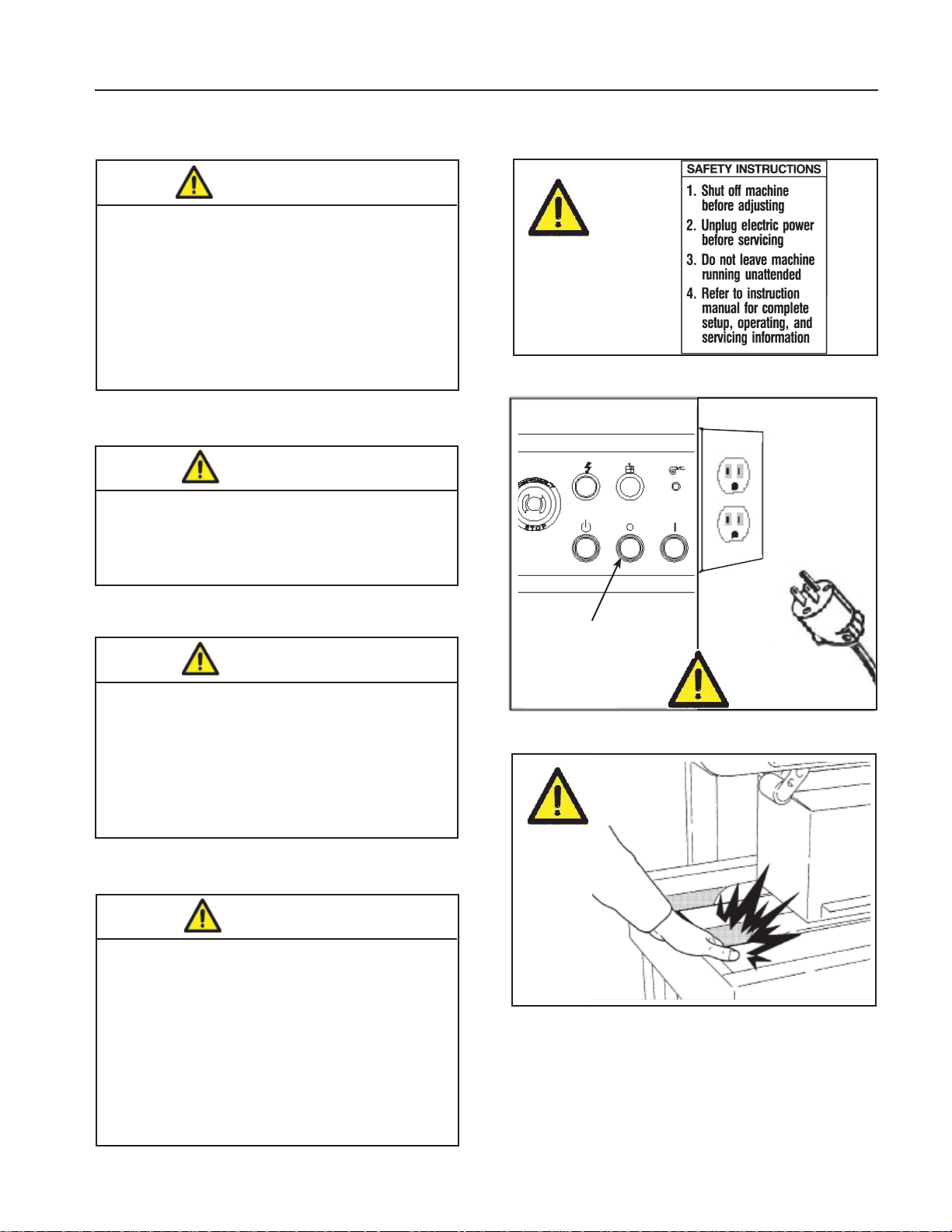
Figure 3-1
E-Stop
3.2 Explanation of Signal Word and
Possible Consequences
This safety alert symbol identifi es
important messages in this manual.
READ AND UNDERSTAND THEM
BEFORE INSTALLING OR
OPERATING THIS EQUIPMENT.
CAUTION:
WARNING:
Indicates a potentially hazardous
situation, which, if not avoided,
may result in minor or moderate
injury and/or property damage.
Indicates a potentially hazardous
situation, which, if not avoided,
could result in death or serious
injury and/or property damage.
The machine is provided with a LATCHING EMER-
GENCY STOP BUTTON (Figure 3-1); when this
button is pressed, it stops the machine at any point
in the working cycle. Maintain clear access to power
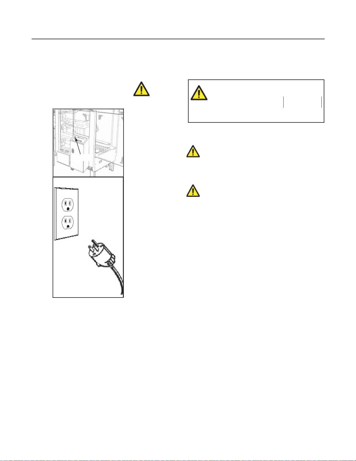
cord while machine is operating. Disconnect plug
from power source before machine maintenance
(Figure 3-1). Also disconnect air if the machine has
a pneumatic system. Keep this manual in a handy
place near the machine. This manual contains information that will help you to maintain the machine in
a good and safe working condition.
800rf-NA
5
2012 March
Page 18
3-SAFETY (continued)
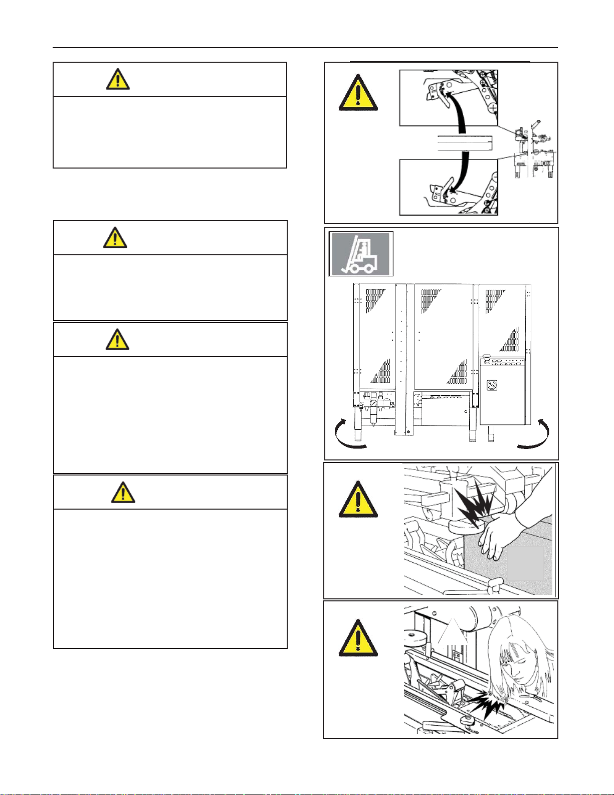
3.3 Table of Warnings
WARNING
• To reduce the risk associated with
mechanical and electrical hazards:
− Read, understand, and follow all safety
and operating instructions before
operating or servicing the case sealer.
− Allow only properly trained and
qualifi ed personnel to operate and
service this equipment.
WARNING
• To reduce the risk associated with
hazardous voltage:
− Position electrical cord away from foot
and vehicle traffi c.
Figure 3-2
WARNING
• To reduce the risk associated with
pinches, entanglement and
hazardous voltage:
− Turn electrical supply off and
disconnect before performing any
adjustments, maintenance or
servicing the machine or taping heads.
WARNING
• To reduce the risk associated with
pinches and entanglement hazards:
− Do not leave the machine running
while unattended.
− Turn the machine off when not in use.
− Never attempt to work on any part of
the machine, load tape, or remove
jammed boxes from the machine while
the machine is running.
Start
Figure 3-3
Figure 3-4
Important! Cavity in the conveyor bed. Never put your
hands inside any part of the machine while it is
working. Serious injury may occur (Figure 3-4).
800rf-NA
6
2012 March
Page 19
3-SAFETY (continued)
WARNING
• To reduce the risk associated with
sharp blade hazards:
− Keep hands and fi ngers away from
tape cutoff blades under orange blade
guards. The blades are extremely sharp.
Important! Tape cutting blade. Never remove the
safety device which covers the blade on the top
and bottom taping units. Blades are extremely
sharp. Any error may cause serious injuries (Figure 3-5).
Figure 3-5
WARNING
Sharp Blade
WARNING
• To reduce the risk associated with
fi re and explosion hazards:
− Do not operate this equipment
in potentially fl ammable/explosive
environments.
WARNING
• To reduce the risk associated with
muscle strain:
− Use the appropriate rigging and
material handling equipment when
lifting or repositioning this equipment.
− Use proper body mechanics when
removing or installing taping heads
that are moderately heavy or may be
considered awkward to lift.
CAUTION
• To reduce the risk associated with
pinches hazards:
− Keep hands clear of the upper head
support assembly as boxes are
transported through the machine.
− Keep hands, hair, loose clothing, and
jewelry away from box compression rollers.
− Always feed boxes into the machine by
pushing only from the end of the box.
− Keep hands, hair, loose clothing, jewelry
away from moving belts and taping heads.
Figure 3-6
Forklift on Opposite Side
Figure 3-7
Important! Side fl ap compression rollers. Never
keep hands on the box while it is driven by the
belts
Important! Drive belts. Never work on the machine
with loose hair or loose garments such as scarfs,
ties or sleeves. Although protected, the drive
belts may be dangerous
(Figure 3-7).
800rf-NA
(Figure 3-8).
Figure 3-8
2012 March
7
Page 20

3-SAFETY (continued)
3.4 Operator's Qualifi cations
- Machine Operator
- Mechanical Maintenance Technician
- Electrical Maintenance Technician
- Manufacturer’s Technician/Specialist
(See Section 3.11)
3.5 Number of Operators
The operations described below have been analyzed
by the manufacturer; the recommended number of
operators for each operation provides the best and
safest work performance.
WARNING
• To reduce the risk associated with
mechanical and electrical hazards:
− Read, understand, and follow all safety
and operating instructions before
operating or servicing the case sealer.
− Allow only properly trained and
qualifi ed personnel to operate and
service this equipment.
3.9 Personal Safety Measures
Note: A smaller or greater number of operators
could be unsafe.
3.6 Instructions for a Safe Use of the Machine /
Defi nition of Operator's Qualifi cations
Only persons who have the skills described in the
skill levels section should be allowed to work on the
machine. It is the responsibility of the user to appoint
the operators having the appropriate skill level and
the appropriate training for each category of job.
3.7 Residual Hazards
The case sealer 800rf incorporates various safety
protections which should never be removed or
disabled. It is essential that the operator and service
personnel be warned that hazards exist which can-
not be eliminated.
Safety glasses, safety gloves, safety helmet, safety
shoes, air fi lters, ear muffs - None is required except
when recommended by the user.
3.10 Predictable Actions which are Incorrect and
Not Allowed
- Never try to stop/hold the box while being driven
by the belts.
- Never remove or disable the safety devices.
- Only authorized personnel should be allowed
to carry out the adjustments, repairs or main tenance which require operation with reduced
safety protections. During such operations,
access to the machine must be restricted.
When the work is fi nished, the safety protec-
tions must immediately be reactivated.
- The cleaning and maintenance operations must be
performed after disconnecting the electric power.
- Do not modify the machine or any part of it.
3.8 Recommendations and Measures to Prevent
Other Hazards which Cannot be Eliminated
- The operator must stay on the working position
shown in the Operation Section. He must never
touch the running driving belts or put his hands
inside any cavity.
- The operator must pay attention to the blades
during the tape replacement.
800rf-NA
- Clean the machine using only dry cloths or
light detergents. Do not use solvents, petrols, etc.
- Install the machine following the suggested layouts
and drawings.
2012 March
8
Page 21
3-SAFETY (continued)
3.11 Operator's Skill Levels Required to Perform
the Main Operations on the Machine
The Table shows the minimum operator's skill for
each machine operation.
Important: The factory manager must ensure that
the operator has been properly trained on all the
machine functions before starting work.
Skill 1: Machine Operator
This operator is trained to use the machine with the
machine controls, to feed cases into the machine,
make adjustments for different case sizes, to change
the tape and to start, stop and restart production.
Skill 2: Mechanical Maintenance Technician
This operator is trained to use the machine as the
MACHINE OPERATOR and in addition is able to:
• Work with the safety protection disconnected
• Check and adjust mechanical parts
• Carry out machine maintenance operations/repairs
He is not allowed to work on live electrical components
Operator's Skill Levels Required to Perform the Main Operations on Machine
Operation Machine Status
Skill 2a: Electrical Maintenance Technician
This operator is trained to use the machine as the
MACHINE OPERATOR and in addition is able to:
• Work with the safety protection disconnected
• Check and adjust mechanical parts
• Carry out machine maintenance operations / repairs / adjustments / repair electrical components
He is allowed to work on live electrical panels,
connector blocks, control equipment, etc.
Skill 3: Specialist from the Manufacturer
Skilled operator sent by the manufacturer or its
agent to perform complex repairs or modifi cations
(on agreement with the customer).
WARNING
• To reduce the risk associated with
mechanical and electrical hazards:
− Allow only properly trained and qualifi ed
personnel to operate and service this machine
Required
Operator
Skill
Number of
Operators
Machine installation and setup Running with safety
protections disabled
Adjusting box size
Tape replacement
Blade replacement Electric power
Drive belt replacement Electric power
Ordinary maintenance Electric power
Extraordinary mechanical
maintenance
Extraordinary electrical
maintenance
Stopped by pressing the
EMERGENCY STOP
button
Stopped by pressing the
EMERGENCY STOP
button
disconnected
disconnected
disconnected
Running with safety
protections disabled
Running with safety
protections disabled
2 and 2a 2
11
11
21
21
21
31
2a - 3 1
800rf-NA
9
2012 March
Page 22
3-SAFETY (continued)
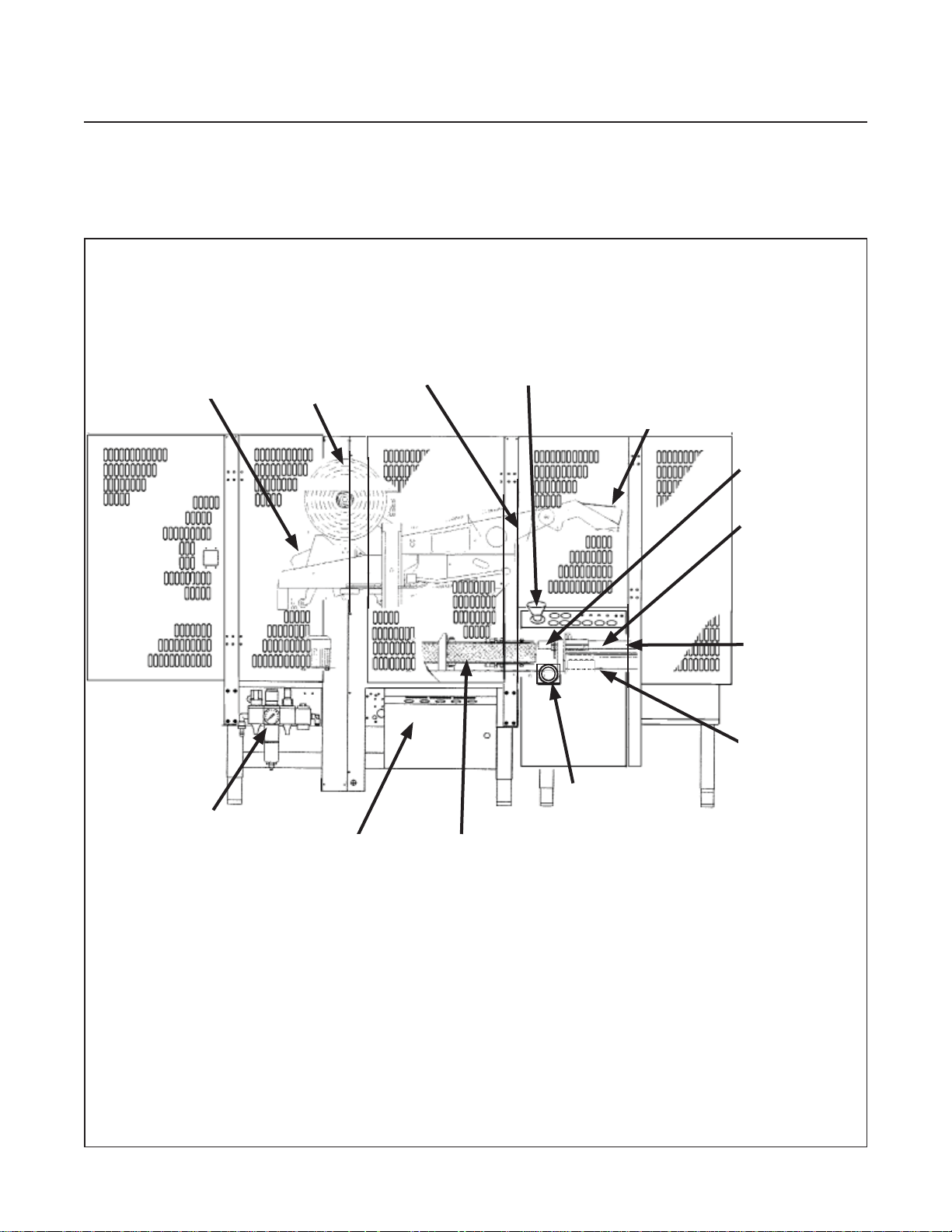
3.12 Component Locations
Refer to Figure 3-9 below to acquaint yourself with the various components and controls of the case sealer.
Also refer to Manual 2 for taping head components.
Upper Head
Assembly
Pneumatics
Top Taping
Head
Tape Roll
Air Control
Assembly
Side Flap
Folding Arm
Auto-Centering
Side Belt Drive
Assemblies
E-Stop
Switch
Main
Power
Switch
Rear Flap
Folding Arm
Case-
Positioning
Fork Assembly
Case
Centering
Rails
Powered/
Gated
Infeed
Conveyor
Main
Controls
Panel
Figure 3-9—800rf Case Sealer Components (Left Front View)
800rf-NA
10
2012 March
Page 23
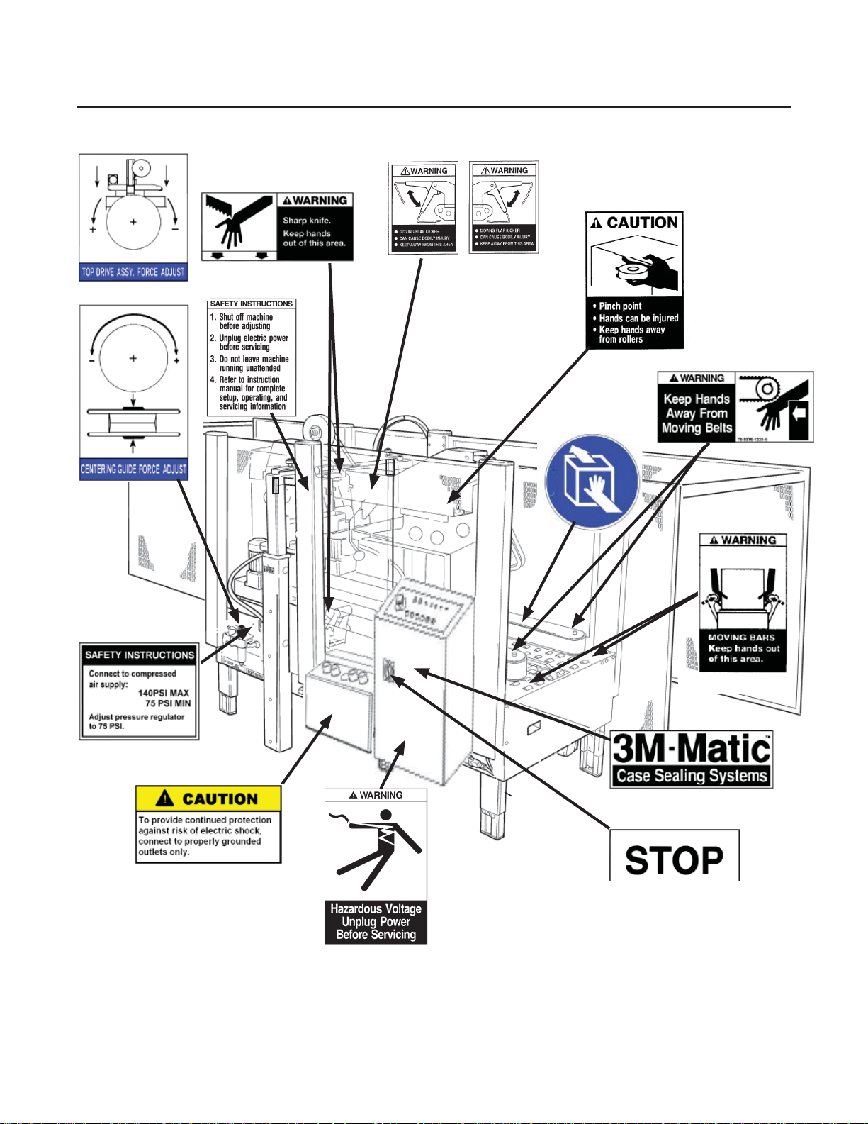
Important Safeguards (continued)
78-8070-1333-5
78-8070-1317-8
78-8070-1336-8
78-8113-6882-4
on Tape Head
78-8113-8912-9
78-8113-6883-2
78-8070-1366-5
78-8070-1331-9
78-8137-0886-0
78-8113-6750-3
78-8137-1331-6
78-8070-1329-3
Figure 1-1 – Replacement Labels/3M Part Numbers
800rf-NA
11
78-8070-1339-2
3M Logo
(not shown)
78-8137-0221-0
78-8062-4266-1
78-8095-1141-9
78-8060-8481-6
Leg Height Adjustment Label
(not shown)
2012 March
Page 24
4-SPECIFICATIONS
4.1 Power Requirements
Electrical: 115 Volt, 60Hz, 3.8 A (440 watts)
(*Note: Electric Information may not relect machine electrical settings/requirements in your area)
The machine is equipped with a 2.4m [8 foot] standard neoprene covered power cord and a grounded plug.
Contact your 3M Representative for power requirements not listed above.
Pneumatic – 6 bar gauge pressure [87 PSIG] @ 21 C, 1.01 bar [3.75 SCFM] at 15 boxes per minute A
pressure regulator is included
Machine requires 75 – 140 PSIG
[5.2 – 9.5 BAR] 7.0 SCFM
[11.89 m3/h 21oC, 101 kPa] at the regulator, maximum at maximum cycle rate.
The optimum operating set point on the gauge is 95 – 100 PSIG.)
4.2 Operating Rate
Box drive belt speed is approximately 0.5 m/s [100 feet per minute].
Infeed conveyor speed: 21m/min
Production = 600 boxes/hour (average)
4.3 Operating Conditions
Use in dry, relatively clean environments at 4.4o C to 48.9o C [40o F to 120o F] with clean, dry boxes.
Note: Machine should not be washed or subjected to conditions causing moisture condensation on
components.
WARNING
• To reduce the risk associated with fi re
and explosion hazards:
− Do not operate this equipment in poten-
4.4 Tape
Scotch® pressure-sensitive fi lm box sealing tapes.
4.5 Tape Width
36mm [1 1/2 inch] minimum to 50mm [2 inch] maximum
800rf Case Sealer. This model offers 3-inch wide upper and lower AccuGlide™ 3 Taping
Heads for tape widths from 2 inches [48 millimeters] to 3 inches [72 millimeters].
800rf-NA
tially fl ammable or explosive environments.
2012 March
12
Page 25

4-SPECIFICATIONS (continued)
4.6 Tape Roll Diameter
Up to 410mm [16 inch] maximum on a 76.2mm [3 inch] diameter core.
(Accommodates all system roll lengths of Scotch
®
fi lm tapes.)
4.7 Tape Application Leg Length – Standard
70mm ± 6mm [2 3/4 inch ±1/4 inch]
Tape Application Leg Length – Optional
50mm ± 6mm [2 inch ±. 1/4 inch]
(See "Removing Taping Heads Procedure – Changing the Tape Leg Length")
4.8 Box Board
Style – regular slotted containers – RSC
125 to 275 P.S.I. bursting test, single wall or double wall B or C fl ute.
23-44 lbs. per inch of width Edge Crush Test (ECT)
4.9 Box Weight and Size Capacities
A. Box Weight, fi lled: 65 lbs. [2 kg–30 kg] ,maximum. Minimum must be suffi cient to hold case on the
conveyor bed with bottom fl aps fl at.
B. Box Size: Minimum Maximum
Length – 200mm [8.0 inch] 600mm [23.5 inch]
Width – 160mm [6.3 inch]* 500mm [20 inch]
Height – 140mm [5.5 inch] 500mm [20 inch]
(See "Special Set-Up Procedures".)
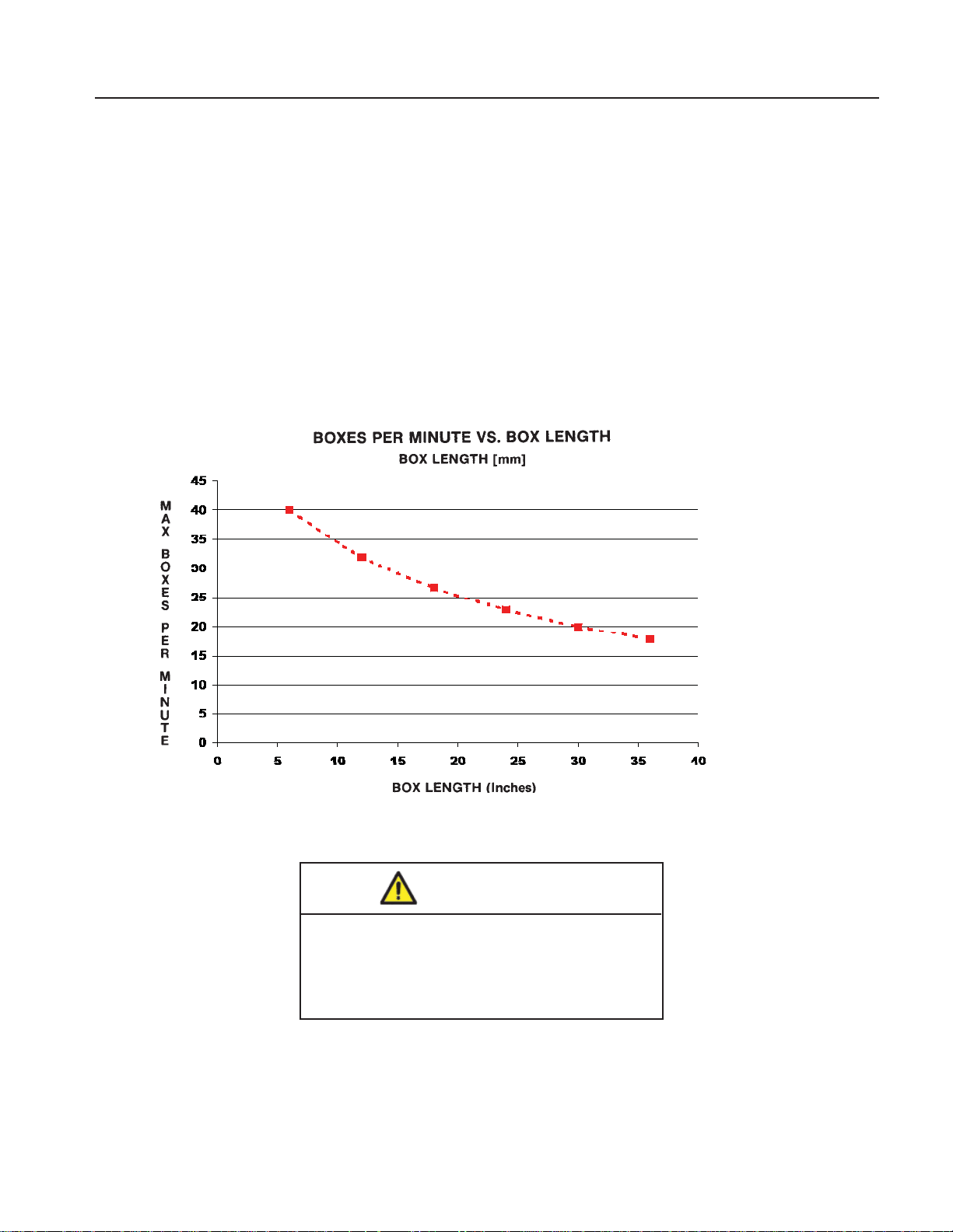
Note: The case sealer can accommodate most boxes within the size range listed above. However, if the box
length (in direction of seal) to box height ratio is 0.6 or less, test run several boxes to ensure proper
machine performance.
DETERMINE THE BOX LIMITATIONS BY COMPLETING THIS FORMULA:
BOX LENGTH IN DIRECTION OF SEAL = SHOULD BE GREATER THAN 0.6
BOX HEIGHT
Any box ratio approaching this limitation should be test run to ensure performance.
800rf-NA
13
2012 March
Page 26
4-SPECIFICATIONS (continued)
4.10 Machine Dimensions
Max. 2050mm
Min. 1830mm
3308mm
694mm 1520mm 1094mm
892mm
920mm
4.11 Machine Noise Level:
Acoustic pressure measured at a distance of 1m. from machine with
Scotch PVC adhesive tape in operation; 78dB Acoustic radiation pressure at 1.6m. height with
Scotch PVC adhesive tape in operation; 73dB Measurement taken with appropriate instrument:
(Type SPYRI-MICROPHON 11).
4.12 Set-Up Recommendations:
1121mm
• Machine must be level.
• Customer supplied infeed and exit conveyors (if used) should provide straight and level box entry and exit.
• Exit conveyors (powered or gravity) must convey sealed boxes away from machine.
800rf-NA
14
2012 March
Page 27
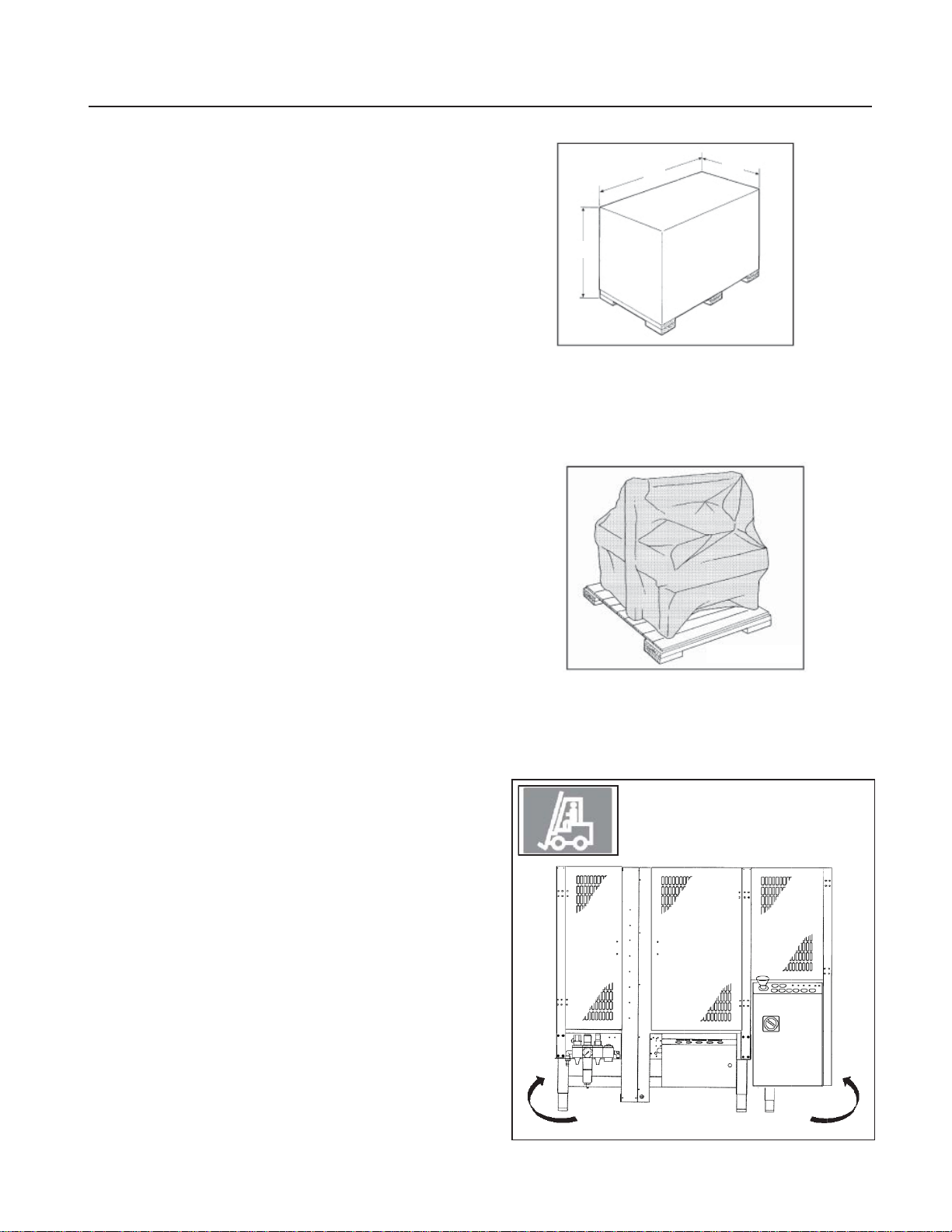
5-SHIPMENT-HANDLING-STORAGE, TRANSPORT
5.1 Shipment and Handling of Packed Machine
The machine and the infeed conveyor are shipped in
2 separate packings, fi xed on a wooden pallet. They
can be uplift with a normal forklift. The standard packing is suitable for surface and air transportation. Oversea packing on request.
Packing dimensions
800rf
l = length: 2880mm:
w = width: 1480mm
h = height: 2050mm
Weight: 617kg
Packaging Overall Dimensions (Figure 5-1)
5.2 Packaging for Overseas Shipment
(Optional - Figure 5-2)
The machines shipped by sea freight are covered by
an aluminum/polyester/polythene bag which
contains dehydrating salts.
W
L
L
H
H
W
Figure 5-1
5.3 Handling and Transportation of Uncrated
Machine
The uncrated machine should not be moved except for
short distances and indoors ONLY. Without the supporting pallet, the machine is exposed to damage and
may cause injuries. To move the machine use belts or
ropes, paying attention to place them in the points indicated using care to not interfere with the lower taping
head (Figure 5-3).
5.4 Storage of the Packed or Unpacked Machine
If the machine is not used for a long period,
please take the following precautions:
- Store the machine in a dry and clean place.
- If the machine is unpacked it is necessary to
protect it from dust.
- Do not stack anything over the machine.
Figure 5-2
Figure 5-3
800rf-NA
Forklift on Opposite Side
2012 March
15
Page 28
6-UNPACKING
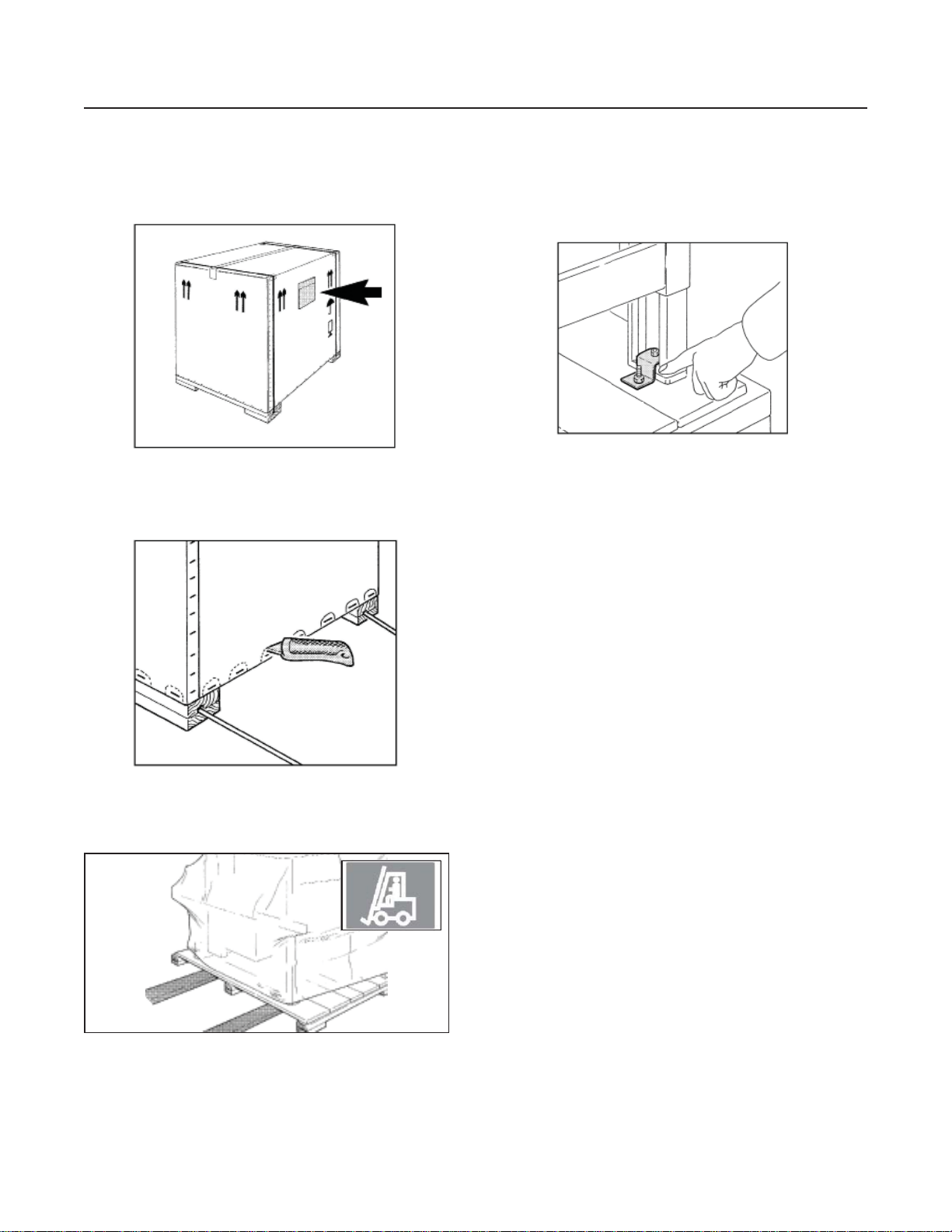
6.1 Uncrating
The envelope attached to the shipping box contains
the uncrating instructions of the machine (Figure 6-1).
Figure 6-1
Cut straps. Cut out staple positions along the bottom
of the shipping box or remove staples with an
appropriate tool (Figure 6-2).
Removal of Pallet
Loosen and remove nuts and brackets using the
open end spanner supplied in the tool box (Figure 6-4).
Figure 6-4
A cardboard box is located under the machine body.
Retrieve the instruction manual for additional procedures of the set up. The box also contains parts re-
moved for shipping, spare parts and tools.
Cut the stretch fi lm and remove the control board, the
guards panel and the accessories box.
Figure 6-2
After cutting out or removing the staples, lift the
shipping box in order to clear the machine
(two persons required).
Figure 6-3
Transport the machine with a fork-lift truck to the operating position. Lift the pallet at the point indicated by
labels on the front, back, and right side of the machine
Figure 6-3 (weight of machine + pallet =
See Specifi cations).
6.2 Disposal of Packaging Materials
The 800rf package is composed of:
- Wooden pallet
- Cardboard shipping box
- Wooden supports
- Metal fi xing brackets
- PU foam protection
- PP plastic straps
- Dehydrating salts in bag
- Special bag of laminated polyester/aluminium/
- Polyethylene (sea freight package only)
- Polyethylene protective material
For the disposal of the above materials, please follow
the environmental directives or the law in your country.
800rf-NA
16
2012 March
Page 29
7-INSTALLATION
7.1 Operating Conditions
The machine should operate in a dry and relatively
clean environment (See Specifi cations).
7.2 Space Requirements for Machine Operation
and Maintenance Work
Minimum distance from wall (Figure 7-1):
A = 1000mm.
B = 700mm.
Minimum height = 2700mm.
B
A
7.3 Tool Kit / Parts Supplied with the Machine
Figure 7-1
WARNING
• To reduce the risk associated with
muscle strain:
− Use the appropriate rigging and
material handling equipment when
lifting or repositioning this equipment.
− Use proper body mechanics when
removing or installing taping heads
that are moderately heavy or may be
considered awkward to lift.
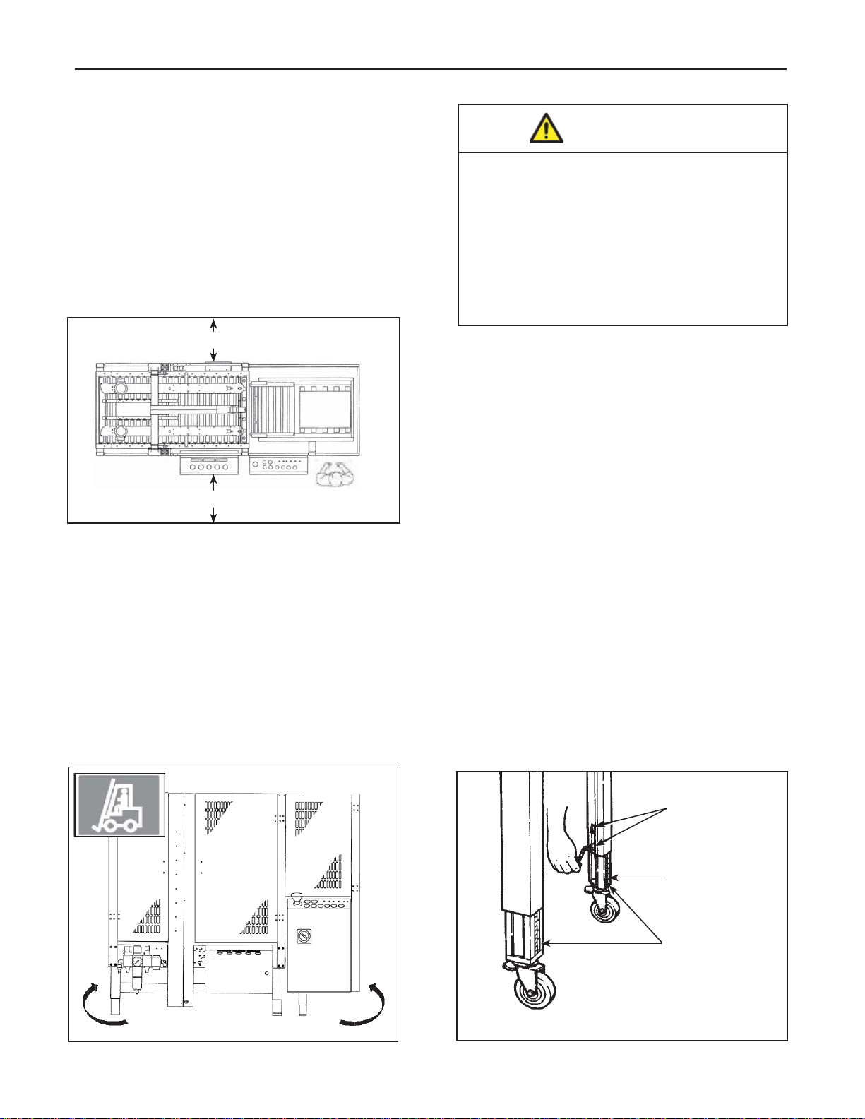
7.4 Machine Positioning / Bed Height
Lift the machine with belts or ropes paying attention
to place the belts in the points (Figure 7-2).
To set the machine bed height, do the following:
The legs on the case sealer can be adjusted to obtain
different bed heights from the factory set-point. The
bed height can be set from 25-7/8 inches [657mm]
minimum through 32 inches [815mm] maximum. Set
the bed height as follows:
A tool kit containing some tools are supplied with
the machine. These tools should be adequate to
set-up the machine, however, other tools supplied
by the customer will be required for machine
maintenance.
The crate should also contain the following:
• One warning beacon with bracket (electrically
connected, but not mounted in place)
Figure 7-2
1. Block up the case sealer frame to allow adequate
leg adjustment.
2. Using a 6mm hex key wrench, loosen, but do not
remove, two (2) M8 x 16mm socket-head cap
screws in one leg. Refer to Figure 7-3.
3. Using the height label as a guide, adjust the leg
length to the desired conveyor bed height. Retighten the two (2) screws to secure the leg.
4. Adjust the remaining legs in the same way.
M8 x 16mm
Socket Head
Screws
Adjustable
Legs
Height
Label
Forklift on Opposite Side
800rf-NA
Figure 7-3
2012 March
17
Page 30
7-INSTALLATION (continued)
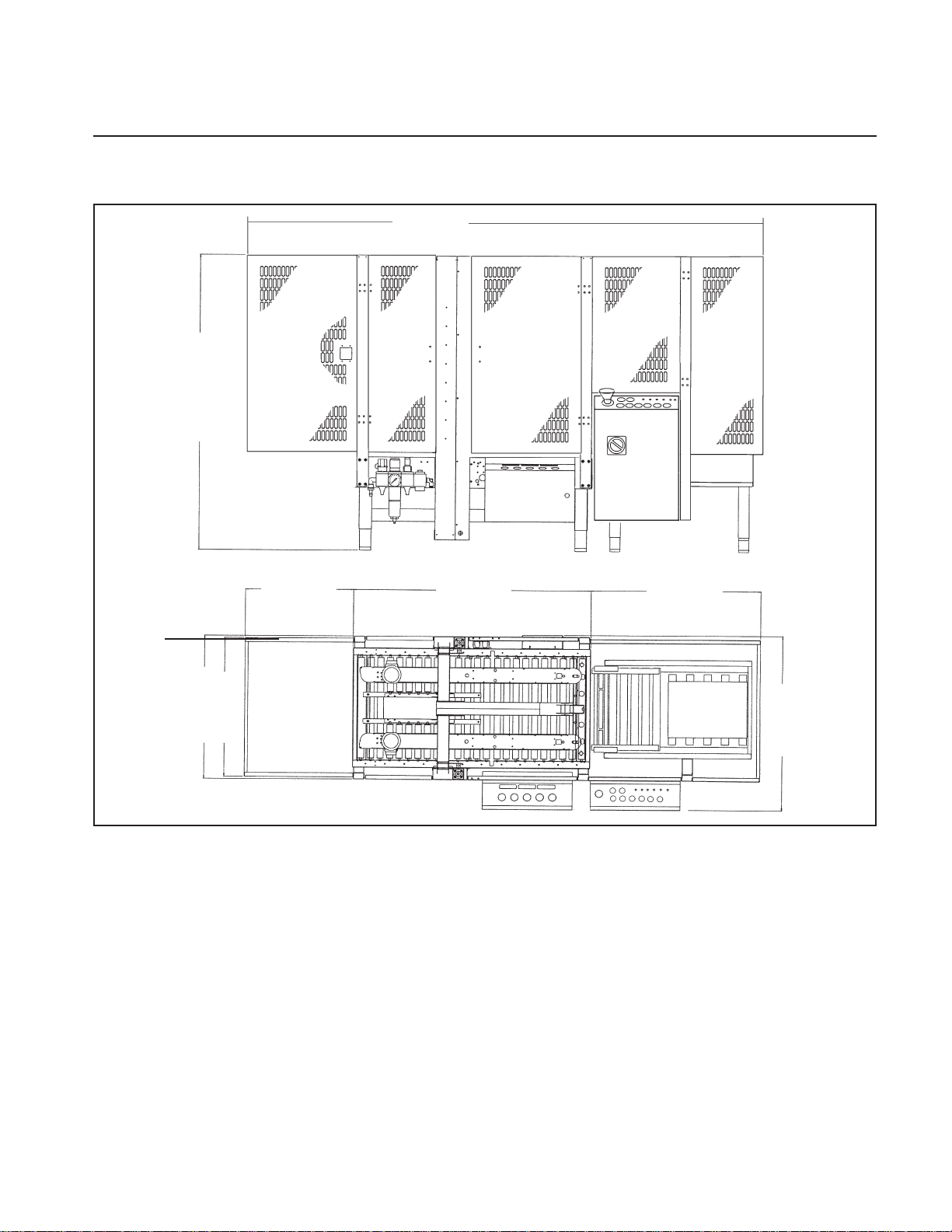
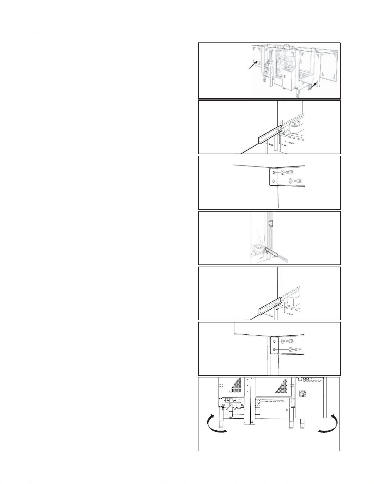
7.5 Safety Guards: Inside and Outside
Machine Emergency Stop Push-Button
Position and assemble the inside (A) and outside (B)
guard panels with the upper and bottom brackets
and stiffening profi le plates as shown in the pictures
(Figure 7-4).
Inside Safety Guards
Support brackets (upper and bottom); 4+4 socket
head screws each bracket (Figure 7-5).
Stiffening profi le plate (upper): 2+2 socket head
screws (Figure 7-6).
Outside Safety Guards
Support brackets (upper and bottom);
4+4 socket head screws each bracket.
Left hand bracket (with pre-assembled photocell);
Right hand bracket (with pre-assembled refl ector).
Assemble the emergency push button unit as shown
(Figure 7-7 & 7-8).
Figure 7-4
Figure 7-5
Figure 7-6
Figure 7-7
B
A
Stiffening profi le plate (upper): 2+2 socket head
screws (Figure 7-9).
7.6 Connection between the Infeed Conveyor
800rf
Lift the infeed conveyor placing the forks under the
points where there are the labels (Figure 7-10).
800rf-NA
Figure 7-8
Figure 7-9
Forklift on Opposite Side
Figure 7-10
2012 March
18
Page 31

7-INSTALLATION (continued)
(infeed conveyor attachment continued)
Approach the infeed conveyor to the machine and fi x
it using the screws previously removed (Figure 7-11).
B10, B1, B2 infeed conveyor photocells connections
(Figure 7-12).
WARNING
• To reduce the risk associated with
mechanical and electrical hazards:
− Allow only properly trained and qualifi ed
personnel to operate and/or service this
equipment
Figure 7-11
Figure 7-12
B10
B1
B2
Insert the B10, B1 photocells screw connector in
the plug on the sealing machine bench as shown.
Connect the cable with screw connector deriving from
the machine to the relative B2 photocell on the infeed
conveyor (Figure 7-13).
WARNING
• To reduce the risk associated with
impact hazards:
− Always use appropriate supporting
means when working under the upper
drive assembly
Connect air tubes from the sealing machine to the
conveyor centering guides cylinder connectors (1) and
to conveyor belt cylinders (2). Connects the air tubes
to the connectors above mentioned pay attention to
the reference numbers (Figure 7-14).
Figure 7-13
2
Figure 7-14
B2
B2
VSA VSB
B10
B1
V11AV11B
2
1
800rf-NA
19
2012 March
Page 32

7-INST ALLATION AND SET-UP (continued)
7.6 Pneumatic & Control Board Connections
(continued)
- Connect an air tube to the ON/OFF valve and
attach it with a strap.
Minimum inside diameter of the tube 10mm;
air pressure 6 BAR.
- Give air to the machine with the ON/OFF valve
(Figure 7-15).
Position the control board near the machine. Feeder
cables: Connect the cable with multipolar connectors
from the machine and from conveyor to the control
board (Figure 7-16).
Figure 7-15
Front and back junction boxes connections (1, 2 -
Figure 7-17 & 7-18):
Figure 7-16
Figure 7-17
1
800rf-NA
2
Figure 7-18
2012 March
20
Page 33

7-INST ALLATION AND SET-UP (continued)
(Pneumatic & Control Board Connections - continued)
Front junction box connector (Figure 7-20).
Figure 7-19
Rear junction box connector. (Figure 7-21).
Figure 7-20
Figure 7-21
800rf-NA
21
2012 March
Page 34

7-INST ALLATION AND SET-UP (continued)
7.7 Preliminary Electric Check-Out
Before connecting the machine to the mains please
carry out the following operations:
- Make sure that the socket is provided with a
ground protection circuit and that both the mains
voltage and frequency meet the indications on the
name plate of the machine.
- Check that the connection of the machine to the
mains meets the provisions of law and/or the
safety regulations in your country.
- Installed power = 0,620 kW
- Connect the power cable (A
to an electric socket c
- Standard power supply (See Specifi cations).
7.8 Check-Out Phases
(For Three-Phases Only)
Procedure to be followed in order to connect correctly
the position of the phases:
- Set the main switch 1 in ON (I) position
(Figure 7-23).
- Check that safety guard panels are clearly shuts;
- Release the emergency stop push buttons rotating
them clockwise (Figure 7-24).
- Push the AUXILIARIES button 3;
- Push the RESET button 4;
- Push the START button 5;
(Figure 7-25).
) of the control board
1
Figure 7-23
2
2 E-Stop
Figure 7-24
Check the rotation direction of the side drive belts. In
case of wrong direction of rotation operate as follows:
- Push the STOP (O) button 6 and disconnect the
plug (Figure 7-26).
- Invert two phases on the terminals of the plug;
- Repeat the above mentioned procedure.
A
Figure 7-22
800rf-NA
22
Figure 7-25
3
6
5
4
Figure 7-26
2012 March
Page 35

7-INST ALLATION AND SET-UP (continued)
7.9 Completion of Taping Heads
See Manual 2 for Complete Instructions:
1. Place the Upper Taping Head in a convenient
working position
.2. Use Figure 7-22 and tape threading label.
Position the tape supply roll so the adhesive
side of tape is facing the front of the taping head
as it is pulled from the supply roll.
3. Attach the threading needle to the end of the
roll. Guide the threading needle around the wrap
roller (Position 1) then back around the oneway tension roller (Position 2).
4. Continue pulling the threading needle down and
guide it between the two (2) rollers on the apply
arm (Position 3).
5. Pull the threading needle down until the tape
travels between the apply plate and the ears of
the apply arm (Position 4) until it extends past
the applying roller. When properly threaded the
adhesive side of the tape should be facing the
knurled rollers at position 2 and also position 3.
6. Cut away any excess tape and repeat steps for
Lower Taping Head.
#2
Figure 7-27
#3
#4
#1
One Way
Tension
Roller
Tension
Wrap
Roller
Knurled
Roller
Wrap
Roller
Applying
Roller
Threading
Needle
Important – Do not cut against the apply roller -
roller damage could occur.
800rf-NA
23
2012 March
Page 36

8-CONTROLS
8.1 Controls Board
1. Main switch (Figure 8-1).
2. Emergency stop push button
(lockable)
3. Auxiliaries push button
(control board electrical components
habilitation)
4. Reset push button
(new work cycle predisposition )
5. Start push button
6. Stop push button
7. Voltage warning light
8. Thermal switch warning light
9. Warning (fl ashing light + buzzer on top guard-
not shown)
10. Operating mode panel (Figure 8-2).
a) Selector switch
1) Operating mode:
‘unchanging box size’
2) Operating mode: automatic’
3) Operating mode:‘transit only’
11. Warning lights panel
a) Cycle time out
b) Minimum gap between side belts
c) Emergency (emergency push
button pressed or safety guard opened)
d) Full sealing line
e) Low air pressure
f) Tape end/breakage
Figure 8-1
Figure 8-2
2
7
8
11
3
6
5
4
10
1
11
f) e) c) b) a) d)
10
ON
OFF
2
3
1
2. Lockable emergency stop push button on
Control Panel (Figure 8-3).
Front Junction Box Controls (Figure 8-4).
1. Centering guide pressure regulator
2. Side belts (motorizations) pressure regulator
3. Box height pick-up pressure regulator
4. Upper unit pressure regulator
800rf-NA
24
2
Figure 8-3
Figure 8-4
E-Stop
4
3
2
1
2012 March
Page 37

9-OPERATION
9.1 Operation
- Give air to the machine by the ON/OFF valve, set
the main switch to ON (I) position;
- Close the safety guards; release the E-stops;
- Press AUXILIARIES button,
- Press RESET button; press START button.
The box, after passed the infeed conveyor belt,
obscures the fi rst photocell (Figure 9-1)
When the second photocell is obscured the infeed
conveyor belt goes down in order to stop the next
box. The side guides A align the box.
The next box obscuring the fi rst photocell cause the
infeed conveyor belt stoppage (Figure 9-2).
Figure 9-1
A
Figure 9-2
The side guides open and the box obscures the third
photocell. The side drive belts B go against the box
and, if the box is longer than 500mm, the rear fl ap
folder is controlled (Figure 9-3).
When the 4th photocell is obscured, the side drive
belts stop. The gate between the rollers, positions
the box correctly
(Figure 9-4).
B
Figure 9-3
Figure 9-4
The upper group then comes down on the box after
folded the front fl ap, the height pick-up device stops
the upper group descent (Figure 9-5).
Figure 9-5
2012 March800rf-NA
25
Page 38

9-OPERATION (continued)
Simultaneously the rear fl ap is folded the fork goes
down and the side belts restart to run (Figure 9-6).
The side fl aps are folded (Figure 9-7).
Figure 9-6
C
The two taping heads seal the box with adhesive
tape (Figure 9-8).
When the box has passed the fi fth photocell, the
upper group goes up, the side drive belts open and
the infeed conveyor belt (on which awaits
the next box) comes up and restarts (Figure 9-9).
The sealing machine begins again with a new cycle.
Figure 9-7
Figure 9-8
800rf-NA
26
Figure 9-9
2012 March
Page 39

9-OPERATION (continued)
Important! If, for any reason, the box should
stop inside the machine, the machine will stop
operating after 10 seconds. To remove the box
and restart, operate as follows:
- press the E-stop,
- open the safety guard,
- remove the box,
- close the safety guard an release the E-stops,
- press the AUXILIARIES push-button;
- press the RESET push-button,
- press the START (I) button to start the cycle
9.2 Operation Methods
The 800rf works only in automatic:
- Safety guard closed,
- E-stop released,
- START (I) button pressed, air circuit open.
Automatic Operating Modes
- Unchanging box size (selector switch 10 on
1 pos.): the machine acknowledges the size of the
fi rst box. The upper unit maintains its position along
whole production. Introducing a box of a different
size with consequent machine jam the same stop
after 10 seconds with activation of the ’‘cycle time
out’‘ warning light on the control board.
- Automatic (selector switch 10 on 2 pos.): the
machine acknowledges the box size whenever a
new box is placed on the infeed conveyor belt.
- Transit only (selector switch 10 on 3 pos): upper
taping unit out of operation; the box is sealed only
on the bottom side. Removing the bottom taping
unit the boxes can be simply moved inside-outside;
a useful condition when the sealing machine is
placed in an automatic packaging line.
9.3. Stop Methods
Figure 9-10
2
Figure 9-11
3 5 4
6
453
E-Stop
Normal Stop:
STOP (O) push button 6 on control board
panel: the push-button must be pressed at
the working cycle end.
To restart press RESET 4 then START 5.
EMERGENCY STOP:
Lockable E-stops pressed or safety guard open.
They stop the machine at any point of the cycle;
also pneumatic circuit are disconnected. To restart
release the E-stops and close the safety guards as
necessary and then:
- Press AUXILIARIES 3 push-button
- Press RESET 4 push-button,
- Press START 5 push-button (Figure 9-11).
800rf-NA
27
2012 March
Page 40

9-OPERATION (continued)
9.4 Alarms
Warning light a: Thermal switch activation
(motor overload)
- The machine cannot be started; machine stops if
it is running
- To restart press 3, after 4, then 5 push-buttons.
Warning light b: Time out cycle (the machine will
stop when the cycle taping boxes is not done just
in time as preselected; 10 seconds approximately).
- machine stop.
- to restart press 4, 5 push-buttons; if necessary,
open a safety guard to eliminate a jam,
press 3, 4, 5 push-buttons.
Warning light c: Minimum gap between side belts
(box size below allowed minimum dimensions or
no box)
a) b)c)d) e)f)g)
- machine stop.
- to restart press 4, 5 push-buttons; if necessary,
open a safety guard to eliminate a jam,
press 3, 4, 5 push-buttons.
Warning light d: Emergency
(emergency push button pressed or safety
guard opened).
- machine stop, pneumatic circuit disconnected.
- to restart press 3, 4, 5 push-buttons.
Warning light e: Full taping line
- Temporary stop of the machine, the outside line
photocell is obscured; the cycle restart just
when the box is removed and so the above
mentioned photocell is reactivated.
Warning light f: Low air pressure
(min. 6 bar or no air)
- the machine cannot be started, machine stops if it
is running;
- to restart press 4, 5 push-buttons
3 5 4
Figure 9-12
Warning light g: Tape end/breakage
- the machine cannot be started, machine stops if
it is running;
- to restart press 3, 4, 5 push-buttons
800rf-NA
28
2012 March
Page 41

10-SAFETY DEVICES OF THE MACHINE
10.1 Blade and Safety Guards
Both the top and bottom taping units have a blade
guard (See Manual 2: AccuGlide™ 3 Taping
Heads - 2 Inch).
WARNING
• To reduce the risk associated with
sharp blade hazards:
− Keep hands and fi ngers away from tape
cutoff blades under orange blade guards.
The blades are extremely sharp.
2050mm
1830mm
3308mm
Rear E-Stop
E-Stop
Power
Start
Stop
Figure 10-2
Safety Guard
It limits the access to the machine, protecting the
operator from the moving parts (Figure 10-1).
Figure 10-1
WARNING
• To reduce the risk associated with
hazardous voltage:
− Position electrical cord away from foot
and vehicle traffi c.
10.2 Emergency Stop Button
The box drive belts are turned on and off with the
electrical switch on the side of the machine frame.
The machine electrical supply can be turned off
by pressing the latching emergency stop switch.
To restart machine, rotate the emergency stop
switch clockwise to release the switch latch.
Restart machine by turning the On/Off switch to
the Off (O) position and then to the On (I) position
(Figure 10-1).
WARNING
• To reduce the risk associated with
mechanical and electrical hazards:
− Allow only properly trained and qualifi ed
personnel to operate and service this
equipment.
10.3 Stop Switches
The Model 800rf Type 40800 Case Sealer is equipped
with three STOP switches. Their locations are shown
in Figure 10-2. Pressing either of the red E-Stop
switches stops the machine, removing electrical power
and air pressure from the case sealer. To restart the
machine, you must turn and release the E-Stop switch
and then press the RESET button and the START (I)
button on the Electrical Control Panel.
Pressing the STOP (O) button on the Electrical Control
Panel stops the machine and does not remove power
from the controller. To restart the machine, you must
press the RESET button and then the START (I) button.
10.4 Electric System
The electric system is protected by a ground wire
whose continuity has been tested during the fi nal
inspection. The system is also subject to insulation
and dielectric strength tests.
Note: The case sealer has a circuit breaker
located in the electrical enclosure on the machine
frame. If circuit becomes overloaded and circuit
breaker trips, unplug the machine electrical
cord and determine cause of overload. After two
minutes, reset the circuit breaker. Plug machine
electrical cord into outlet and restart machine by
pushing the On/Off switch to the On (I) position.
Important: The use of an extension cord is not
recommended.
800rf-NA
29
2012 March
Page 42

11 - SET UP AND ADJUSTMENTS
11.1 Tape Loading on the Top Unit
Insert a tape roll on the drum and push it fully forward.
Attach the tape leg to the threading tool (supplied with
the tools kit) Figure 11-1.
Insert the plastic threading leader through the taping
unit. Take care to keep hands away from the tape
cutting blades (Figure 11-2 and 11-3).
Figure 11-1
Figure 11-2
Figure 11-3
Follow the path through the unit as shown on picture
(Figure 11-4) and make sure that the adhesive side is
placed on the correct side.
Pull and cut off the excess tape using a pair of
scissors as shown (Figure 11-5 and 11-6).
Figure 11-6
Figure 11-4
Adhesive
Adhesive
Adhesive
Adhesive
Adhesive
Adhesive
Figure 11-5
800rf-NA
30
2012 March
Page 43

11 - SET UP AND ADJUSTMENTS (continued)
11.2 Tape Loading on the Bottom Unit
Remove the bottom taping unit from its housing and
put it on a working bench (Figure 11-7).
- Put a tape roll on the drum and thread the tape
through the unit as shown on the label in the
same manner as for the top unit (Figure 11-8).
- Put the bottom unit back into its housing.
11.3 Tape Drum Alignment
Check the centering of the tape on the rollers of
the taping unit. If necessary unscrew the nut 1 and
adjust the screw (2) (Figure 11-9).
11.4 Tape Drum Friction Brake Adjustment
Check the tape tension:-with PVC the tape drum
must be free-with OPP the tape drum must be
slightly frictioned
11.5 Adjustment of Taping Units According to
the Type of Boxes
Adjust the main spring:-decrease the spring load
for light boxes;-increase the spring load for heavy
boxes (Figure 11-10).
CAUTION
Figure 11-7
Figure 11-8
#2
#3
#4
#1
One Way
Tension
Roller
Tension
Wrap
Roller
Knurled
Roller
Wrap
Roller
Applying
Roller
Threading
Needle
1
1
• To reduce the risk associated with
pinches hazards:
− Keep hands clear of the upper head
support assembly as boxes are
transported through the machine.
− Keep hands, hair, loose clothing, and
jewelry away from box compression rollers.
− Always feed boxes into the machine by
pushing only from the end of the box.
− Keep hands, hair, loose clothing, and jewelry
away from moving belts and taping heads.
Important – If drive belts are allowed to slip on
box, excessive belt wear will occur.
Note - For belt replacement and tension
specifi cations - refer to Section 13 /
Maintenance and Repairs).
800rf-NA
31
Figure 11-9
Figure 11-10
2
2
_
2012 March
+
Page 44

11 - SET UP AND ADJUSTMENTS (continued)
11.6 Main Pressure Regulator
A) it adjusts the entry working pressure
B) gauge to read the entry air pressure
Optimal working pressure: 6 BAR
Feeding tube diameter: 10mm
Note: in case the working pressure is below 6 BAR or
the feeding tube has a small diameter, some
malfunctions can happen! (ex: the upper group
comes down, the rear fl ap folder works but the
machine stops)
11.7 Centering Guides Pressure
1) Pressure regulator with built-in pressure
gauge. The pressure regulator 1 located on
the front junction box adjusts the pressure
of the centering guides of the infeed conveyor.
Working pressure: 2,5÷3,5 bar (entry pressure: 6 bar).
Figure 11-11
A
B
Figure 11-12
11.8 Side Drives Pressure Adjustment
2) Pressure regulator with built-in pressure
gauge. The pressure regulator 2 located
on the front junction box adjusts the
pressure of the side drives against the box.
- Increase for strong or heavy boxes.
- Decrease for light boxes.
Working pressure: 2,5÷3,5 bar
CAUTION
• To reduce the risk associated with
pinches hazards:
− Keep hands clear of the upper head
support assembly as boxes are
transported through the machine.
− Keep hands, hair, loose clothing, and
jewelry away from box compression rollers.
− Always feed boxes into the machine by
pushing only from the end of the box.
− Keep hands, hair, loose clothing, and
jewelry away from moving belts and
taping heads.
Figure 11-13
Figure 11-14
2
Figure 11-15
800rf-NA
32
2012 March
Page 45

11 - SET UP AND ADJUSTMENTS (continued)
11.9 Box Height Pick-up
3) Pressure regulator with built-in pressure
gauge. The pressure regulator 3 adjusts the
pressure according to the board strength.
- Decrease in case of light boxes.
- Increase in case of strong boxes.
- Minimum pressure must be adjusted so
that the paddle returns automatically in
position once the box is passed.
Figure 11-16
Working pressure: 0,5÷1,0 bar (entry pressure: 6 bar).
11.10 Upper Unit Descent Pressure Regulator
4) Pressure regulator with built-in pressure
gauge. The pressure regulator 4 adjusts the
pressure according to the board strength.
- Decrease in case of light boxes.
- Increase in case of strong boxes.
Working pressure: 2÷3 bar (entry pressure: 6 bar)
2
3
Figure 11-17
800rf-NA
33
Figure 11-18
2
3
Figure 11-19
2012 March
Page 46

11 - SET UP AND ADJUSTMENTS (continued)
11.11 Pneumatic Speed Regulators
A) Upper unit ascent-descent speed regulators
B) Centering guides (infeed conveyor) speed
regulators
C) Side belts opening-closing speed regulators
Side belts opening-closing speed regulators.
These are not common operations. They have to be
made only when it has been necessary to work on the
pneumatic cylinder.
To change the speed, do as follows:
1) Unscrew the locking nut 1
2) Turn the knob 2 clockwise to reduce the belts
closing speed; counter-clockwise to increase the
belts closing speed.
3) unscrew the locking nut 3
4) turn the knob 4 clockwise to reduce the belts
opening speed, counter-clockwise to increase the
belts opening speed.
Figure 11-20
A
B C
Centering guides opening-closing speed regulators
These are not common operations. They have to be
made only when it has been necessary to work on the
pneumatic cylinder.
To change the speed, do as follows:
1) unscrew the locking nut 1
2) turn the knob 2 clockwise to reduce opening
speed; counter-clockwise to increase opening
speed.
3) unscrew the locking nut 3
4) turn the knob 4 clockwise to reduce closing
speed, counter-clockwise to increase closing
speed.
Upper unit ascent-descent speed regulators
These are not common operations. They have to be
made only when it has been necessary to work on the
pneumatic cylinder.
To change the speed, do as follows:
1) unscrew the locking nut 1
2) turn the knob 2 clockwise to reduce the descent
speed; counter-clockwise to in-crease the
descent speed.
3) unscrew the locking nut 3
4) turn the knob 4 clockwise to reduce the ascent
speed, counter-clockwise to increase the ascent
speed.
A
1
2
DESCENT
B
1
2
OPENING
C
1
2
CLOSING OPENING
Figure 11-21
3
4
ASCENT
Figure 11-22
3
4
CLOSING
Figure 11-23
3
4
800rf-NA
34
2012 March
Page 47

11 - SET UP AND ADJUSTMENTS (continued)
11.12 Speed Regulators of the Rear Flap Folder
These are not common operations. They have to be
made only when it has been necessary to work on the
pneumatic cylinder
To change the speed, do as follows:
The speed of the rear fl ap folder unit can be adjusted
by the fl ow regulators mounted on the pneumatic
cylinders.
.
2
1
Figure 11-24
It is necessary to introduce a screw driver into the hole
corresponding to the regulator:
1) to adjust the descent speed of the arm.
2) to adjust the ascent speed of the arm.
3) to adjust the descent speed of the fl ap
folder.
4) to adjust the ascent speed of the fl ap folder.
11.13 Adjustment of the Upper Unit Height
In case the height of the box to be sealed is not higher
then 300mm, it is possible to stop the ascent of the upper group so to reduce the time of the sealing cycle.
To limit the upper group ascent move down the magnetic sensor 2 located on the air cylinder 1, machine
side operator, after have removed the guard.
Turn the cam screw 3 to reposition the sensor.
Figure 11-25
1
1
3
4
Position the sensor so that the upper unit stops at
100mm above the box height.
800rf-NA
Figure 11-26
35
2
3
2012 March
Page 48

11 - SET UP AND ADJUSTMENTS (continued)
11.14 Adjustment of the Sensor that Stops the
Descent of the Upper Unit
The descent of the upper group is stopped when the
sensor 1 is activated (yellow led up).
The sensor is mounted on the cylinder 2 by the
support 3.
o change the intervention time of the sensor do as
T
follows:
1) Loosen, the screw 4 of the support;
2) Move the support with the sensor along
the cylinder;
B
A
3 2
1
4
Figure 11-27
T owards A
Towards A to delay the braking.
Towards B to anticipate the braking.
Figure 11-28
T owards A
Figure 11-29
Towards B
Figure 11-30
Towards B
Before
After
Before
800rf-NA
Figure 11-31
36
After
2012 March
Page 49

11 - SET UP AND ADJUSTMENTS (continued)
11.15 Adjustments of the Side Compression Rollers
To increase or decrease the pressure of the side rollers
on the box, do as follows:
- loosen the nuts;
- change the position of the rollers;
- lock the nuts.
- increase the pressure when the upper fl aps
are not well closed after the sealing.
Figure 11-32
+
+
-
-
- decrease the pressure when the upper fl aps
are one upon the other.
11.16 Adjustment of the Magnetic Limit Switch on
the Side Drives Air Cylinder
Limit switch 2 on the air cylinder body - check maximum
closure of the side drives avoiding that the compression
rollers hit the upper unit. Some little adjustments are
possible by moving the limit switch longitudinally on the
cylinder body; to do this, loosen the cam screw 3.
Before
Figure 11-33
Before
Figure 11-34
After
After
1
1
800rf-NA
Figure 11-35
37
3
2
2012 March
Page 50

11 - SET UP AND ADJUSTMENTS (continued)
6 5 4 3 2 1
SD
Figure 11-36
11.17 Use and Adjustments of the Photocells
Photocell 1
The photocell does not operate at the fi rst machine starting ; when it is obscured by the next box the motorized
plane of the infeed conveyor stops. No adjustment is necessary
Photocell 2
When is obscured by the box the motorized plane goes down and the side guides center the box. No adjustment
is necessary.
Photocell 3
It controls the closure of the side drives and and the descent of the rear fl ap folder. The position can be changed
according to box lengthy; move the photocell towards D for long boxes, towards S for short boxes.
Photocell 4
It stops the side drives and control the upper unit descent. No adjustment is necessary.
Photocell 5
When the box is passed it controls the machine reset for a new working cycle. No adjustment is necessary.
Photocell 6
When is obscured stops the machine and activates the ‘full line’ warning light on the control board. It's a temporary stop; he machine restarts just when the box is removed an so the photocell is rearmed. No adjustment is
necessary.
.
800rf-NA
38
2012 March
Page 51

12-TROUBLE-SHOOTING
The Troubleshooting Guide lists some possible machine problems, causes and corrections.
Also see Manual 2 "Troubleshooting" for taping head problems.
12.1 Troubleshooting Guide
Problem
Tape is not centered on the box.
The length of the front tape leg on
the box is not constant.
The blade does not cut properly.
Cause
The side belts are not correctly
positioned.
The box fl aps are not centered.
Tape is not positioned in the
center of the taping head.
Tape path through the heads is
not correct.
Type unwind tension too loose.
Knurled roller friction too loose.
Taping head idler rollers
Blade dirty of adhesive.
Tape tension not enough.
Springs on cutting lever not strong
enough.
Correction
Check the position.
Check the fl aps dimensions; the
fl aps must be equals.
Adjust the tape position.
Check.
Adjust the tension.
Adjust
Clean and lubricate the rollers
Clean.
Increase the friction on the coreholder.
Replace.
The tape is not well applied on the
rear of the box.
The head comes down and crash
the box.
800rf-NA
Blade damaged (broken teeth).
Blade does not cut properly.
Main spring is not tensioned.
Adhesive residues on the head
rollers.
The box does not stop properly
against the gate (stop device) on
the machine rollers.
The box height pick-up is not
correctly positioned.
The magnetic limit switch on the
the box height pick-up cylinder is
not correctly positioned or is not
working.
39
Replace the blade
Replace/Clean.
Adjust the spring tension.
Clean and lubricate the rollers.
Check the photocell position
Check the pressure value
Check for jams (inside frictions)
Check position of the magnetic
limit switch. Check magnetic limit
switch ope-ration.
(continued on next page)
2012 March
Page 52

12-TROUBLE-SHOOTING
Troubleshooting Guide
(continued)
Problem
The box is not dragged under the
head.
Cause
The box is too full load; box side
fl aps are opened.
Driving pulley rings on motorizing
side units are worn out.
Motorizing side units low
pressure.
The head is not correctly
positioned; it is too down.
Defective head power valve
Correction
Check.
Replace as necessary.
Replace valve
Check pressure value (working
pressure)
Check the magnetic limit switch
position on the box height pick-up
cylinder.
800rf-NA
40
2012 March
Page 53

13-MAINTENANCE AND REPAIRS
13.1 Safety Measures (see section 3)
Carrying out maintenance and repairs may imply
the necessity to work in dangerous situations.
13.3 Recommended Frequency of Inspection and Maintenance Operations
Operation Frequency Qualifi cation Sections
Inspection safety features daily 1 13.4
Cleaning of machine weekly 1 13.5
Cleaning of cutter blade weekly 2 13.6
Oiling of felt pad weekly 2 13.7
Lubrication monthly 2 13.7-13.8
Blade replacement when worn 2 See Manual 2
Drive belt replacement when worn 2 13.10
13.4 Inspections to be Performed Before and
After Every Maintenance Operation
Before every maintenance operation, turn the main
switch OFF (O) and disconnect. During the maintenance operation, only properly trained and qualifi ed
personnel must work on the machine. At the end
of every maintenance operation check the safety
devices.
13.2 Tools and Spare Parts Supplied with
the Machine
See Spare Parts Order Section.
13.7 Cleaning of Cutter Blade
Qualifi cation 2
Should tape adhesive build-up occur, carefully wipe
clean with oily cloth or brush
vents the build-up of tape adhesive.
(See manual 2.)
(Figure 13-1). Oil pre-
13.5 Check Effi ciency of Safety Features
1. Blade guard assembly upper taping head
2. Blade guard assembly lower taping head
3. Latching Emergency stop button with mechanical
lock (interrupt supply of electrical power)
4. Turn the main switch STOP/OFF (O)
5. Safety guards top drive belts
13.6 Cleaning of Machine
Qualifi cation 1
A weekly cleaning with dry rags or diluted detergents
is necessary. Cardboard boxes produce a signifi cant
quantity of dust and paper chips when processed
or handled in case sealing equipment. If this dust is
allowed to build up on machine components, it can
cause component wear and over-heating of drive
motors. The dust build up is best removed from the
machine with a vacuum cleaner. Depending on the
number of cartons processed, this cleaning should
be done weekly. Excessive build-up that cannot be
removed by vacuuming should be removed with a
damp cloth.
WARNING
• To reduce the risk associated with
mechanical and electrical hazards:
− Read, understand, and follow all safety
and operating instructions before
operating or servicing the case sealer.
− Allow only properly trained and qualifi ed
personnel to operate and service this
equipment.
• To reduce the risk associated with
pinches, entanglement and hazardous
voltage:
− Turn electrical and air supply off and
disconnect before performing any adjust ments, maintenance or servicing the
machine or taping heads.
800rf-NA
41
2012 March
Page 54

13-MAINTENANCE AND REPAIRS (continued)
13.8 Securities Check-up
ape units blade guards;
1) T
2) Lockable emergency stop push-buttons;
3) Rigid protection plate mounted on the side
drives;
4) Safety guards;
13.9 Machine Lubrication
Lubricate quarterly with grease/Metal/metal
1) Slide cross bar ball guides for side drives
(grease nipples on the blocks) ;
2) Columns-upper unit cross bar ball guides
(grease nipples on the blocks);
Figure 13-1
1
1
1
1
1
2
2
3) Side compression rollers ball guides
(grease nipples on the blocks).
13.10 Suggested Products for Lubrication
Grease Type:
Synthetic spray lubricant.
Figure 13-2
3
Figure 13-3
800rf-NA
42
2012 March
Page 55

Maintenance (continued)
WARNING
• To reduce the risk associated with
mechanical and electrical hazards:
− Turn electrical and air supply off
and disconnect before performing any
adjustments, maintenance or servicing
the machine or taping heads
• To reduce the risk associated with
impact hazards:
− Always use appropriate supporting
means when working under the upper
drive assembly
13.11 Side Drive Belts Replacement
Operator - Skill Level 2.
Note: in order to convey the case correctly, it is nec-
essary that both belts have the same level of wear.
Remove the plug from the mains and turn the air off
Disconnect the plug from the socket.
Off
Figure 13-4
Figure 13-5
Loosen and remove the bolts that fi x the connecting
rod to the side fl ap folder.
Remove the side drives locking screws.
Remove the side drive and place it on a working table.
Figure 13-6
Figure 13-7
800rf-NA
43
Figure 13-8
2012 March
Page 56

13-MAINTENANCE AND REPAIRS (continued)
Remove the locking screws and the protection
covers.
Loosen the tensioning screws.
Figure 13-9
Figure 13-10
Release the nut of the tensioning plate.
Remove and replace the drive belt.
Important Before setting the new belt, check the
wear of the orange plastic rings on the drive
pulleys: replace them if they are worn out.
WARNING
• To reduce the risk associated with
mechanical and electrical hazards:
− Turn electrical and air supply off and
disconnect before performing any
adjustments, maintenance or servicing
the machine or taping heads
Figure 13-11
Figure 13-12
Figure 13-13
800rf-NA
44
2012 March
Page 57

Adjustments (continued)
13.12 Box Drive Belt Tension
The two (2) continuously moving drive belts convey boxes through the tape applying mechanism.
The box drive belts are powered by an electric gear motor.
Tension adjustment of these belts may be required during normal operation. Belt tension must be adequate to
positively move the box through the machine and the belts should run fully on the surface of the pulleys at each
end of the frame. The idler pulleys on the infeed end are adjusted in or out to provide proper belt tension. Each
belt is adjusted separately.
Belt tension is obtained by tightening the adjustment screw so that a moderate pulling force of 3.5kg [7lbs.]
applied at the mid span, as shown in Figure 13-14, will defl ect the belt 25mm [1 inch]. This will assure positive
contact between the belt and the drive pulley on the discharge end of the drive assembly.
Box Drive Belt
Discharge End Infeed End
Figure 13-14 Box Drive Belt Tension Adjustment
13.13 Adjustment of the Upper Assembly
Descent Brake
3.5kg (7lbs) Pull Force
with 25mm (1 inch) at Mid span
The brake adjustment must be done when the upper
group does not stay in position and tends to come
down further.
- Loosen the screw 1
- Turn the ring nut 2 clockwise
- Tighten the screw 1
Do this operation on both cylinders.
800rf-NA
2
1
Figure 13-15
2012 March
45
Page 58

THIS PAGE IS BLANK
46
Page 59

13-MAINTENANCE AND REPAIRS (continued)
13.14 List of the Maintenance Operations
Date: Description of Operation
________ ________________________________________________________________
________ ________________________________________________________________
________ ________________________________________________________________
________ ________________________________________________________________
________ ________________________________________________________________
________ ________________________________________________________________
________ ________________________________________________________________
________ ________________________________________________________________
________ ________________________________________________________________
________ ________________________________________________________________
________ ________________________________________________________________
________ ________________________________________________________________
________ ________________________________________________________________
________ ________________________________________________________________
________ ________________________________________________________________
________ ________________________________________________________________
________ ________________________________________________________________
________ ________________________________________________________________
________ ________________________________________________________________
________ ________________________________________________________________
________ ________________________________________________________________
________ ________________________________________________________________
________ ________________________________________________________________
________ ________________________________________________________________
________ ________________________________________________________________
________ ________________________________________________________________
________ ________________________________________________________________
________ ________________________________________________________________
________ ________________________________________________________________
________ ________________________________________________________________
________ ________________________________________________________________
________ ________________________________________________________________
________ ________________________________________________________________
________ ________________________________________________________________
________ ________________________________________________________________
________ ________________________________________________________________
________ ________________________________________________________________
________ ________________________________________________________________
________ ________________________________________________________________
800rf-NA
47
2012 March
Page 60

THIS PAGE IS BLANK
48
Page 61

14-ADDITIONAL INSTRUCTIONS 15-ENCLOSURES / SPECIAL INFO.
14.1 Information for Disposal of Machine
The machine is composed of the following materials:
- Steel structure
- Nylon rollers
- Drive belts in PVC
- Nylon pulleys
For machine disposal, follow the regulations
published in each country.
14.2 Emergency Procedures
In case of danger/fi re:
Disconnect plug of power cable from power supply.
(Figure 14-1)
IN CASE OF FIRE
Use a fi re extinguisher containing CO2 (Figure 14-2).
15.1 Statement of Conformity
See Section 1.
15.2 Emission of Hazardous Substances
Nothing to report
15.3 List of Safety Features
List of components/assemblies with safety
functions
- LATCHING EMERGENCY STOP BUTTON
- Thermal cut-out relay
- Fixed guards upper drive belts
- Blade guard assemblies on both taping heads
- Important: Install earth wire protection on
electrical installation.
All safety features/components must be explained
and highlighted to all operators and to the person
responsible for spare parts in order to ensure that
these components are always on hand or ordered
as a priority procedure.
Figure 14-1
Figure 14-2
ONLY USE ORIGINAL REPLACEMENT PARTS
15.4 Copies of Test Reports, Certifi cations (etc.)
Required by User
NA
800rf-NA
49
2012 March
Page 62

THIS PAGE IS BLANK
50
Page 63

16-Electrical Technical Diagram
• To reduce the risk associated with mechanical and electrical hazards:
− Turn electrical and air supply off and disconnect before performing any adjustments,
maintenance or servicing the machine or taping heads
WARNING
800rf-NA
51
2012 March
Page 64

16-TECHNICAL DIAGRAMS
16.1 Electric Diagram - Page 2A
(see next Page 2B)
4
3B
4C
4
800rf-NA
52
2012 March
Page 65

16-TECHNICAL DIAGRAMS (continued)
16.1 Electric Diagram - Page 2B
(see previous Page 2A)
3
4
3A
4A
3B
4C
4
800rf-NA
53
2012 March
Page 66

16-Pneumatic Technical Diagram
Stop Box Cylinder
Close Cylinder 2Close Cylinder 1Gate CylinderGate CylinderMotor CylinderCentering Cylinder
Column CylinderBlock Pressers
800rf-NA
54
2012 March
Page 67

16-TECHNICAL DOCUMENTATION AND INFORMATION (continued)
16.3 Spare Parts Order
The following parts are normal wear items and should be ordered and kept on hand as used.
Qty. Part Number Description
4 78-8054-8841-4 Belt – Drive W/Pin
Also see Manual 2 for recommended taping head spare parts.
Label Kit
In the event that any labels are damaged or destroyed, they must be replaced to ensure operator safety.
A label kit, part number 78-8098-9177-9 is available as a stock item. It contains all the safety labels used on
the 800rf Random Case Sealer.
Tool Kit
A tool kit, part number TBA, is supplied with the machine. The kit contains the necessary open end and hex socket
wrenches for use with the metric fasteners on the case sealer. The threading tool, part number 78-8076-4726-4,
contained in above kit is also available as a replacement stock item.
Replacement Parts Ordering Information and Service
Refer to the fi rst page of this instruction manual "Replacement Parts and Service Information".
800rf-NA
55
2012 March
Page 68

THIS PAGE IS BLANK
56
Page 69

800rf Random Case Sealer, Type 40800
Frame Assemblies
To Order Parts:
1. Refer to fi rst illustration, Frame Assemblies, for the Figure Number that identifi es a specifi c portion of the
machine.
2. Refer to the appropriate Figure or Figures to determine the parts required and the parts reference number.
3. The Parts List that follows each illustration, includes the Reference Number, Part Number and Part
Description for the parts on that illustration.
Note – The complete description has been included for standard fasteners and some commercially
available components. This has been done to allow obtaining these standard parts locally, if desired.
4. Order parts by Part Number, Part Description and Quantity required. Also include the model/machine name,
machine type, and serial number that are located on the identifi cation plate.
5. Refer to the fi rst page of this instruction manual “Replacement Parts and Service Information” for
replacement parts ordering information.
Important – Not all the parts listed are normally stocked items. Some parts or assemblies shown are
available only on special order. Contact 3M/Tape Dispenser Parts to confi rm item availability.
Options and Accessories
For additional information on the options and accessories listed below, contact your 3M Representative.
Part Number Option/Accessory
78-8069-3983-7 Caster Kit Attachment
70-0064-4963-4 AccuGlide 3 Upper Taping Head - 2 inch, Type 10800
70-0064-4962-6 AccuGlide 3 Lower Taping Head - 2 inch, Type 10800
78-8095-4854-4 2-Inch Tape Edge Fold Attachment, Upper Head
78-8095-4855-1 2-Inch Tape Edge Fold Attachment, Lower Head
800rf-NA
57
2012 March
Page 70

THIS PAGE IS BLANK
58
Page 71

800rf Random Case Sealer
Figure 15077
Figure 15076
Figure 15072
Figure 10440
Figure 15071
Figure 15294
15082
All Pneumatic
Components
and Plumbing
Frame
Assemblies
800rf-NA
Figure 15075
Figure 15078
Figure 15073
Figure 15096
See End of Manual for Infeed Conveyor
59
Figure 15295
Figure 15079
Illustrations and Parts Lists.
2012 0DUFK
Page 72

800rf
800rf
12
19
18
13
15
17
13
11
11
10
8
10
14
7
5
6
9
2
7
16
3
16
4
19
18
1
Figure 15071
800rf-NA
17
2012 0DUFK
60
Page 73

800rf
Figure 15071
Ref. No. 3M Part No. Description
15071-1 78-8119-8507-2 Support Assy - Guide, R/H
15071-2 78-8119-8508-0 Support - Guide, L/H
15071-3 78-8137-3606-9 Height Positioner
15071-4 78-8060-7568-1 Bearing 618/9 / 9 -17-4
15071-5 78-8076-5081-3 Fork - Cylinder
15071-6 78-8060-7566-5 Stud Fork
15071-7 78-8060-7565-7 Ring
15071-8 78-8060-7558-2 Spacer, Cylinder
15071-9 78-8076-5080-5 Guide - Box
15071-10 78-8060-7561-6 Spacer
15071-11 78-8060-7562-4 Spacer
15071-12 26-1002-5836-2 Screw Hex Hd. M6X40
15071-13 26-1003-6916-9 Nut Locking Plastic Insert M6
15071-14 78-8114-4903-8 Screw - Special, M5
15071-15 26-1005-6859-6 Nut Self Locking M-5
15071-16 78-8119-8510-6 Washer - Special
15071-17 78-8017-9170-4 Screw - Phillips FH M4X8
15071-18 26-1003-7957-2 Screw Soc. Hd. Hex Hd.. M6X16
15071-19 26-1000-0010-3 Washer - Flat M6
800rf-NA
61
2012 0DUFK
Page 74

800rf
Figure 10440
800rf-NA
62
2012 0DUFK
Page 75

800rf
Figure 10440
Figure 10440
Ref. No. 3M Part No. Description
10440-1 78-8070-1564-5 Tape Roll Bracket Assembly
10440-2 78-8070-1565-2 Tape Drum Bracket Assembly
10440-3 78-8070-1566-0 Bracket – Tape Drum
10440-4 78-8070-1395-4 Bracket – Bushing Assembly
10440-5 78-8070-1568-6 Cap – Bracket
10440-6 78-8076-4519-3 Shaft – Tape Drum
10440-7 78-8017-9169-6 Nut – M18 x 1
10440-8 78-8098-8827-0 Tape Drum Sub-Assembly - 2 Inch
10440-9 78-8098-8749-6 Tape Drum
10440-10 78-8098-8817-1 Leaf Spring
10440-11 26-1002-5753-9 Screw – Self Tapping
10440-12 78-8060-8172-1 Washer – Friction
10440-13 78-8052-6271-0 Washer – Tape Drum
10440-14 78-8100-1048-4 Spring – Core Holder
10440-15 78-8017-9077-1 Nut – Self Locking, M10 x 1
10440-16 78-8032-0375-7 Screw – Hex Hd, M6 x 16
10440-17 78-8070-1215-4 Spacer – Stud
10440-18 26-1000-0010-3 Washer – Flat, M6
10440-19 78-8010-7169-3 Screw – Hex Hd, M6 x 12
10440-20 78-8060-8474-1 Tape Drum Assembly – 2 Inch Head
10440-21 26-1004-5510-9 Washer - Plain, M10
10440-22 78-8098-8816-3 Latch - Tape Drum
800rf-NA
63
20120DUFK
Page 76

800rf
12
12
13
13
10
11
11
7
7
9
9
8
8
10
6
6
1
1
4
4
2
2
3
3
5
5
Figure 15072
800rf-NA
64
2012 0DUFK
Page 77

800rf
Figure 15072
Ref. No. 3M Part No. Description
15072-1 78-8137-3607-7 Frame - Upper Head- R/H
15072-2 78-8137-3608-5 Frame - Upper Head- L/H
15072-3 78-8137-3609-3 Screw - M8 X 20
15072-4 78-8017-9318-9 Washer-Plain-Metric M8
15072-5 78-8017-9313-0 Nut Self Locking M8 Nick. Pl.
15072-6 78-8137-3601-1 Holder - Upper Head- R/H
15072-7 78-8137-3611-9 Holder - Upper Head- L/H
15072-8 26-1003-5820-4 Screw - Hex Hd..M-5 X 12
15072-9 78-8005-5741-1 Washer - Flat, M5
15072-10 78-8137-0902-5 Knurled Knob
15072-11 78-8094-6247-2 Spacer
15072-12 78-8010-7169-3 Screw - Metric, M6 X 12, Hex Hd..
15072-13 78-8137-3612-7 Rear Plate
800rf-NA
2012 0DUFK
65
Page 78

800rf
1
1
5
5
2
2
4
4
3
4
4
5
5
6
6
7
7
3
14
14
9
9
10
10
10
10
9
9
8
8
12
12
15
15
13
13
11
11
Figure 15073
800rf-NA
66
2012 0DUFK
Page 79

800rf
Figure 15073
Ref. No. 3M Part No. Description
15073-1 78-8137-3613-5 Frame - Bottom Head- R/H
15073-2 78-8137-3614-3 Frame - Bottom Head- L/H
15073-3 78-8054-8862-0 Spacer - 12 X 12 X 1 - M40
15073-4 78-8010-7169-3 Washer - Flat M6
15073-5 26-1000-0010-3 Screw - Metric, M6 X 12, Hex Hd..
15073-6 26-1003-7963-0 Screw - Soc. Hd. M8 X 16
15073-7 78-8017-9318-9 Washer - Plain - Metric M8
15073-8 78-8137-3615-0 Cylinder Support
15073-9 26-1003-7964-8 Screw Soc. Hd. Hex Soc. Dr., M8 X 20
15073-10 78-8017-9318-9 Washer - Plain - Metric M8
15073-11 78-8137-3616-8 Screw Soc. Hd. Hex Hd.. M6 X 60
15073-12 26-1005-6893-5 90 Degree Elbow
15073-13 78-8137-3617-6 Plate - Box-Holder
15073-14 26-1003-7957-2 Screw Soc. Hd. Hex Hd.. M6 X 16
15073-15 26-1000-0010-3 Washer - Flat M6
800rf-NA
67
2012 0DUFK
Page 80

800rf
14
14
15
15
13
13
15
15
12
12
9
9
18
18
17
17
16
16
36
36
41
41
8
8
35
35
38
38
37
37
39
39
33
33
30
30
40
40
31
31
34
34
32
32
Figure 15074
800rf-NA
28
28
29
29
22
22
20
1
1
23
23
20
19
19
27
68
27
21
21
26
26
2
2
25
25
24
24
2012 0DUFK
3
3
11
11
10
10
4
6
6
7
7
4
5
5
Page 81

800rf
Figure 15074
Ref. No. 3M Part No. Description
15074-1 78-8137-3618-4 Crossbar- Drive Assy Guides
15074-2 78-8137-3619-2 Sprocket - 3/8" Assy
15074-3 78-8137-3620-0 Sprocket - 3/8" - 35 Teeth
15074-4 78-8023-2551-0 Bearing - 6005-2RS
15074-5 78-8137-3621-8 Stop Ring
15074-6 78-8052-6709-9 Washer - Special
15074-7 78-8032-0375-7 Screw Metric M6 X 16 Hex Hd..
15074-8 78-8137-3622-6 Rail Linear Guide
15074-9 26-1003-7966-3 Screw, Soc. Hd Hex Soc M8 X 30
15074-10 78-8017-9313-0 Nut Self Locking M8 Nick. Pl.
15074-11 78-8017-9318-9 Washer-Plain-Metric M8
15074-12 78-8137-3623-4 Slide Guide
15074-13 78-8137-3624-2 Lower Block
15074-14 78-8137-3625-9 Vertical Block
15074-15 78-8017-9303-1 Screw - Soc.Hd Hex. Hd M10 X2 0
15074-16 78-8137-3626-7 Side Plate
15074-17 78-8032-0375-7 Screw Metric M6X16 Hex Hd..
15074-18 26-1000-0010-3 Washer - Flat M6
15074-19 78-8137-3627-5 Wishbone - L/H
15074-20 78-8137-3628-3 Wishbone - R/H
15074-21 78-8137-3629-1 Junction For Chain
15074-22 78-8054-8785-3 Rod - Threaded Right/Left
15074-23 78-8060-8488-1 Screw - Hex Hd.. M5 X 20
15074-24 26-1005-6859-6 Nut Self Locking M-5
15074-25 78-8005-5741-1 Washer - Flat, M5
15074-26 78-8046-8269-4 Connecting - LINK - 3/8" Pitch Chain
15074-27 78-8137-3630-9 Chain - P=3/8" - L=57
15074-28 26-1003-7963-0 Screw - Soc. Hd. M8 X 16
15074-29 78-8017-9318-9 Washer-Plain-Metric M8
15074-30 78-8137-3631-7 Swinging Flange
15074-31 78-8137-3632-5 Fixing Plate For Cylinder
15074-32 26-1003-5833-7 Screw Hex Hd. 6 X 30
15074-33 78-8091-0418-1 Nut - Self-Locking, M6
15074-34 26-1000-0010-3 Washer - Flat M6
15074-35 78-8091-0315-9 Elbow - 3199.08.13
15074-36 78-8057-5747-9 Mount, Cylinder Rod End
15074-37 78-8137-3633-3 Buffer For Cylinder
15074-38 78-8060-7699-4 Washer /12-45,5 X 4
15074-39 78-8042-2919-9 Washer - Triple, M6
15074-40 78-8010-7169-3 Screw-Metric, M6 X 12, Hex Hd..
15074-41 26-1017-3313-2 Limit SwitchSME-8M-DS-24V-K-0,3-M8D
800rf-NA
69
2012 0DUFK
Page 82

800rf
4
4
2
2
3
3
12
12
13
13
25
25
3
22
20
20
23
23
22
3
15
15
24
24
19
19
17
17
18
18
16
16
6
6
7
7
26
21
21
26
4
4
14
14
8
8
1
1
11
11
11
11
9
9
4
10
10
4
5
5
Figure 15075
800rf-NA
70
2012 0DUFK
Page 83

800rf
Figure 15075
Ref. No. 3M Part No. Description
15075-1 78-8137-3634-1 Bottom Plate For Side Roller R/H
78-8137-3635-8 Bottom Plate For Side Roller L/H
15075-2 78-8137-3636-6 Top Plate For Side Roller
15075-3 78-8137-3637-4 Block For Union Plates
15075-4 26-1001-9843-6 Screw Flat Soc. Hd.M6 X 16
15075-5 26-1005-5316-8 Screw, Flat Hd. Hex Dr. M5 X 16
15075-6 78-8010-7417-6 Nut - Metric, Hex Stl. M5
15075-7 78-8005-5741-1 Washer - Flat, M5.
15075-8 78-8137-3638-2 Junction
15075-9 78-8114-4977-2 Roller - Compression
15075-10 78-8076-4629-0 Shaft - Roller
15075-11 78-8052-6703-2 Washer - Special
15075-12 26-1003-5842-8 Screw Hex Hd.. M8 X 20
15075-13 26-1004-5507-5 Washer M8
15075-14 78-8076-4664-7 Union - Female
15075-15 78-8137-3609-3 Screw M8 X 20
15075-16 78-8137-3640-8 Rod w/Bearing
15075-17 78-8137-3641-6 Rod - Assy
15075-18 78-8137-3642-4 Rubber Grommet
15075-19 78-8060-7752-1 Bearing - Linear LBCR, O.D. M32
15075-20 78-8137-3643-2 Bushing
15075-21 78-8137-3639-0 Screw - Flat HD, Soc. Dr. M8 X 30
15075-22 26-1004-5507-5 Washer M8
15075-23 78-8017-9313-0 Nut Self Locking M8 Nick. Pl.
15075-24 78-8137-3644-0 Rod - Guide For Side Roller
15075-25 78-8137-3645-7 Slide Guide
15075-26 78-8137-3646-5 Fixing Plate
800rf-NA
71
2012 0DUFK
Page 84

800rf
32
32
33
33
1
1
31
31
6
6
3
3
29
29
4
4
5
5
36
36
35
35
26
26
25
25
28
28
27
27
7
14
14
7
24
24
23
23
34
34
17
17
18
18
9
10
10
9
8
8
12
12
15
15
16
16
13
13
11
11
30
30
800rf-NA
38
38
2
2
37
37
18
18
20
22
22
20
21
18
1721
18
17
23
23
Figure 15076
2012 0DUFK
72
Page 85

800rf
Figure 15076
Ref. No. 3M Part No. Description
15076-1 78-8137-3647-3 Outer Column Assy - R/H
78-8137-3648-1 Outer Column Assy - L/H
15076-2 26-1003-7964-8 Screw Soc. Hd. Hex Soc. Dr., M8 X 20
15076-3 78-8137-3649-9 Rail - Linear Guide
15076-4 78-8076-5477-3 Washer - Special / 6.5 X 20 X 4
15076-5 78-8060-7918-8 Screw Flat Soc. Hd. M6X25
15076-6 78-8010-7418-4 Nut - Metric, Hex, Stl., M6
15076-7 78-8137-3645-7 Slide Guide
15076-8 78-8137-3651-5 Fixing Block, Crossbar
15076-9 26-1003-7965-5 Screw - Soc. Hd. Hx. Soc. M8 X 25
15076-10 78-8137-3652-3 Lockwasher for M8 Screw
15076-11 78-8137-3653-1 Crossbar, Flap Folder
15076-12 78-8137-3654-9 Rail Linear Guide
15076-13 78-8023-2334-1 Screw-Soc. Hd., Hex. Soc.M6 X 25
15076-14 78-8137-3655-6 Stud - Cylinder
15076-15 78-8094-6339-7 Washer - Flat, M16
15076-16 78-8094-6338-9 Nut - Self Locking, M16
15076-17 26-1003-7963-0 Screw - Soc. Hd. M8 X 16
15076-18 78-8017-9318-9 Washer-Plain-Metric M8
15076-20 26-1017-3315-7 Swinging Flange
15076-21 78-8094-6335-5 Stud - Cylinder
15076-22 78-8056-3965-1 Ring - 8 DIN 6799
15076-23 78-8091-0315-9 Elbow - 3199.08.13
15076-24 26-1005-6893-5 90 Degree Elbow
15076-25 26-1017-3313-2 Limit Switch SME-8M-DS-24V
15076-26 78-8057-5747-9 Mount, Cylinder Rod End
15076-27 78-8137-3656-4 Spacer - Cylinder
15076-28 78-8091-0775-4 Nut - M12 X 1.25
15076-29 78-8137-3657-2 Cover - Cylinder, R/H
78-8137-3658-0 Cover - Cylinder, L/H
15076-30 78-8129-6103-1 Screw - Special, M4 X 10
15076-31 78-8137-3659-8 Crossbar, Column
15076-32 26-1003-5829-5 Screw Hex Hd..M6 X 12
15076-33 26-1000-0010-3 Washer - Flat M6
15076-34 78-8137-3660-6 Quick Exhaust
15076-35 78-8060-7532-7 Nut M12 Self-Locking
15076-36 78-8017-9059-9 Washer-Flat For M12 Screw
15076-37 78-8060-7818-0 Screw, Hex Hd.. M4 X 12
15076-38 78-8005-5740-3 Washer Plain - Metric M4 Nick.
800rf-NA
73
2012 0DUFK
Page 86

800rf
28
28
29
29
53
53
52
52
51
51
61
61
58
58
1
1
60
60
59
59
28
28
54
54
25
25
55
55
26
26
57
57
27
27
56
56
13
13
16
16
14
15
15
14
9
24
24
9
45
45
16
16
13
13
22
22
23
23
46
46
18
18
48
48
43
43
19
19
50
50
21
21
10
10
44
44
4
23
23
4
50
50
20
20
2
2
49
49
19
18
19
46
48
48
17
46
17
18
47
47
3
3
32
32
42
42
41
41
5
36
36
37
37
5
31
31
33
33
34
34
35
35
40
40
6
6
38
38
3
3
20
20
43
43
22
22
39
39
10
10
27
27
11
11
12
12
31
31
30
30
Figure 15077
800rf-NA
7
9
5
5
9
74
7
8
8
2012 0DUFK
Page 87

Figure 15077
Ref. No. 3M Part No. Description
15077-1 78-8137-3661-4 Support - Side Flap Folder
15077-2 78-8137-3662-2 Arm - Rear Flap Folder
15077-3 78-8137-3663-0 Support NSK
15077-4 78-8137-3664-8 Spacer - Flap Folder
15077-5 78-8119-8809-2 Rear Flap Folder Assy
15077-6 78-8119-8811-8 Flap Folder Assy - Rear
15077-7 78-8091-0554-3 Shaft - Flap Folder
15077-8 78-8023-2410-9 Bearing - 6000-2RS O.D. M26
15077-9 78-8091-0389-4 Spacer - Bearing
15077-10 78-8054-8944-6 Shaft - 12 X M51
15077-11 78-8057-5747-9 Mount, Cylinder Rod End
15077-12 78-8137-3665-5 Spacer
15077-13 78-8137-3666-3 Spacer For Cylinder
15077-14 78-8054-8946-1 Shaft - 5/8 X M51
15077-15 78-8119-8810-0 Pivot - Rear Flap Folder
15077-16 78-8137-3667-1 Spacer - Rear Flap Folder
15077-17 78-8137-3668-9 Screw, Soc. Hd. Hex Soc M5 X 65
15077-18 26-1003-5829-5 Screw Hex Hd.. M6 X 12
15077-19 78-8094-6166-4 Washer - Star, M6
15077-20 78-8005-5741-1 Washer - Flat, M5
15077-21 26-1005-6859-6 Nut Self Locking M-5
15077-22 26-1003-5829-5 Screw Hex Hd.. M6 X 12
15077-23 78-8010-7169-3 Screw - Metric, M6 X 12, Hex Hd..
15077-24 78-8057-5748-7 Mount, Cylinder Rod End
15077-25 78-8137-3669-7 Bracket
15077-26 78-8076-5076-3 Extension Flap Folder
15077-27 78-8010-7169-3 Screw-Metric, M6 X 12, Hex Hd.
15077-28 78-8017-9066-4 Screw - Metric, M5 X 12
15077-29 78-8137-3670-5 Cover - Rear
15077-30 78-8114-4627-3 Side Flap Folder Assy
15077-31 78-8100-1079-9 Side Flap Folder
15077-32 78-8100-1077-3 Block
15077-33 78-8100-1080-7 Plate - Side Flap Folder
15077-34 78-8017-9318-9 Washer - Plain - Metric M8
15077-35 26-1003-7966-3 Screw, Soc. Hd Hex Soc M8 X 30
15077-36 78-8010-7209-7 Screw, Soc. Hd.M6 X 12
15077-37 78-8042-2919-9 Washer - Triple, M6
15077-38 78-8060-7863-6 Threaded Rod M6 X 20
15077-39 78-8076-4546-6 Knob
15077-40 78-8114-4633-1 Screw - Soc. Hd. Hex Hd. M8 X 100
15077-41 78-8017-9318-9 Washer - Plain - Metric M8
15077-42 78-8017-9313-0 Nut Self Locking M8 Nick. Pl.
15077-43 26-1000-0010-3 Washer - Flat M6.
15077-44 78-8017-9079-7 Ring - Snap For M15 Shaft
15077-45 78-8114-4633-1 Screw - Soc. Hd. Hex Hd.. M8 X 100
15077-46 26-1004-5507-5 Washer M8
15077-47 78-8017-9313-0 Nut Self Locking M8 Nick. Pl.
15077-48 26-1003-5842-8 Screw Hex Hd..M8 X 20
15077-49 78-8100-0833-0 Washer - M8
15077-50 78-8017-9318-9 Washer - Plain - Metric M8
15077-51 26-1003-7964-8 Screw Soc. Hd. Hex Soc. Dr., M8 X 20
15077-52 78-8017-9318-9 Washer - Plain - Metric M8
15077-53 78-8005-5736-1 Lock Washer - For M8 Screw
15077-54 78-8129-6468-8 Union - Straight, BVND-M207
15077-55 78-8129-6469-6 Nut
15077-56 26-1002-5820-6 Screw - Hex Hd. M5 X 16
15077-57 78-8005-5741-2 Washer - Flat, M5
15077-58 78-8137-3671-3 Cover - Upper
15077-59 78-8054-8937-0 Shaft - 12 X M100
15077-60 78-8017-9059-9 Washer-Flat for M12 Screw
15077-61 78-8056-3965-1 Ring - 8 DIN 6799
800rf-NA
75
2012 0DUFK
Page 88

800rf
22
22
20
20
4
4
1
1
1917
19
17
22
14
14
22
9
9
9
9
2
2
3
3
18
18
19
19
7
7
12
12
13
13
11
11
21
21
6
6
5
5
16
16
15
15
Figure 15078
800rf-NA
76
10
10
8
8
2012 0DUFK
Page 89

800rf
Figure 15078
Ref. No. 3M Part No. Description
15078-1 78-8137-3672-1 Fixing Bracket, Box
15078-2 26-1004-5507-5 Washer M8
15078-3 26-1003-5842-8 Screw Hex Hd.. M8 X 20
15078-4 78-8137-3673-9 Fixing Spacer, Box
15078-5 78-8091-0656-6 Screw - Hex. Soc. Hd. M8 X 12
15078-6 78-8017-9318-9 Washer - Plain - Metric M8
15078-7 78-8137-3674-7 Pneumatic Box W/INS
15078-8 78-8137-3675-4 Pneumatic Box Gate W/INS
15078-9 78-8119-8549-4 Lock "Southco"
15078-10 78-8119-8548-6 Foam Rubber
15078-11 78-8137-3676-2 Fixing Plate For Gate
15078-12 78-8129-6293-0 Hinge
15078-13 26-1003-7957-2 Screw Soc. Hd. Hex Hd.. M6 X 16
15078-14 78-8137-3677-0 Flow Regulator Support
15078-15 26-1003-7957-2 Screw Soc. Hd. Hex Hd.. M6 X 16
15078-16 26-1000-0010-3 Washer - Flat M6
15078-17 78-8137-3678-8 Cover For Pneumatic Box
15078-18 78-8137-3679-6 Plate - Pneumatic Box
15078-19 78-8017-9066-4 Screw - Metric, M5 X 12
15078-20 78-8137-3680-4 Adhesive Label - Pneumatic Box
15078-21 78-8114-5064-8 Cap
15078-22 78-8091-0656-6 Screw - Hex. Soc. Hd. M8 X 12
800rf-NA
77
2012 0DUFK
Page 90

800rf
800rf Random Case Sealer
35
35
32
32
36
36
19
19
37
37
16
16
1
1
33
33
34
34
17
17
19
19
47
47
48
48
49
49
50
50
42
43
42
43
46
46
41
41
44
44
45
45
38
38
39
39
40
40
21
21
28
28
27
27
14
14
26
26
23
23
22
22
24
24
25
25
11
11
12
12
13
13
31
31
30
29
29
15
15
30
19
19
Optional
OPTIONAL
18
18
20
20
57
57
10
10
9
9
2
2
3
3
19
19
3
3
7
7
2
2
4
4
Figure 15079 / 1
800rf-NA
55
54
5
8
8
6
6
6
6
5
54
53
53
52
52
78
55
56
56
51
51
2012 0DUFK
Page 91

800rf
Figure 15079 / 1
Ref. No. 3M Part No. Description
15079-1 78-8137-3681-2 Frame - Conveyor
15079-2 78-8129-6370-6 Leg Assy
15079-3 78-8137-3682-0 Leg Assy L=600
15079-4 78-8129-6096-7 Leg
15079-5 78-8129-6371-4 Label - Leg
15079-6 78-8137-0641-9 Pad - Foot
15079-7 78-8137-3683-8 Leg - Inner
15079-8 78-8137-3684-6 Label - Leg
15079-9 78-8137-0635-1 Clamp - Leg
15079-10 78-8129-6100-7 Bracket
15079-11 26-1003-7963-0 Screw - Soc. Hd. M8 X 16
15079-12 78-8017-9318-9 Washer - Plain - Metric M8
15079-13 78-8137-3685-3 Profi le
15079-14 26-1003-7949-9 Screw Soc. Hd. Hex Soc. M5 X 12
15079-15 78-8137-3686-1 Cover - Front, R/H
15079-16 78-8137-3687-9 Cover - Front, L/H
15079-17 78-8137-3688-7 Cover - Rear R/H
15079-18 78-8137-3689-5 Cover - Short
15079-19 78-8017-9066-4 Screw - Metric, M5 X 12
15079-20 78-8137-3690-3 Housing - Wire
15079-21 78-8137-3691-1 Cover - Bottom
15079-22 26-1003-7957-2 Screw Soc. Hd. Hex Hd.. M6 X 16
15079-23 26-1000-0010-3 Washer - Flat M6
15079-24 78-8137-3692-9 Plate - Cover
15079-25 78-8017-9066-4 Screw - Metric, M5 X 12
15079-26 78-8137-3693-7 Bracket for Bulkhead
15079-27 26-1003-7957-2 Screw Soc. Hd. Hex Hd.. M6 X 16
15079-28 78-8042-2919-9 Washer - Triple, M6
15079-29 78-8137-3694-5 Profi le - Cover
15079-30 26-1003-7957-2 Screw Soc. Hd. Hex Hd.. M6 X 16
15079-31 26-1000-0010-3 Washer - Flat M6
15079-32 78-8137-3695-2 Housing - Wire
15079-33 26-1003-7957-2 Screw Soc. Hd. Hex Hd.. M6 X 16
15079-34 26-1000-0010-3 Washer - Flat M6
15079-35 78-8137-3696-0 Cover for Housing - Wire
15079-36 78-8032-0382-3 Screw-Soc.Hex Hd..M5 X 16 Zinc.Pl
15079-37 78-8005-5741-1 Washer - Flat, M5
15079-38 78-8137-3697-8 Bracket For Housing - Wire
15079-39 26-1003-7957-2 Screw Soc. Hd. Hex Hd.. M6 X 16
15079-40 26-1000-0010-3 Washer - Flat M6
15079-41 78-8137-3698-6 Housing - Wire
15079-42 26-1003-7957-2 Screw Soc. Hd. Hex Hd.. M6 X 16
15079-43 26-1000-0010-3 Washer - Flat M6
15079-44 78-8137-3699-4 Cover For Housing - Wire
15079-45 78-8017-9066-4 Screw - Metric, M5 X 12
15079-46 78-8137-3700-0 Block - Support
15079-47 26-1003-7964-8 Screw Soc. Hd. Hex Soc. Dr., M8 X 20
15079-48 78-8094-6227-4 Washer - Special, /8
15079-49 78-8137-3701-8 Profi le, Support - Drive
15079-50 78-8017-9066-4 Screw - Metric, M5 X 12
15079-51 78-8098-9076-3 Caster
15079-52 78-8060-8124-2 Spacer - Caster
15079-53 78-8129-6105-6 Bracket - Wheel
15079-54 78-8017-9059-9 Washer-Flat For M12 Screw
15079-55 78-8060-7532-7 Nut M12 Self-Locking
15079-56 78-8129-6104-9 Set Screw - M8 X 8
15079-57 78-8137-3702-6 Wheel Set- /80
800rf-NA
79
2012 0DUFK
Page 92

800rf Random Case Sealer
800rf
5
5
6
6
4
4
8
8
9
9
27
27
26
26
22
22
18
18
25
25
2
2
3
3
12
7
7
30
30
29
29
10
13
13
10
12
12
1
1
31
31
32
32
12
13
13
28
28
11
11
28
28
18
18
Figure 15079 / 2
800rf-NA
19
19
20
20
21
21
80
15
15
14
14
15
15
22
22
17
17
23
23
16
16
20120DUFK
24
24
14
14
21
21
Page 93

800rf
Figure 15079 / 2
Ref. No. 3M Part No. Description
15079-1 78-8137-3703-4 Support - Plate Connectors
15079-2 26-1003-7957-2 Screw Soc. Hd. Hex Hd.. M6 X 16
15079-3 26-1000-0010-3 Washer - Flat M6
15079-4 78-8137-3704-2 Carter Protection Connectors
15079-5 26-1003-5820-4 Screw - Hex Hd..M-5 X 12
15079-6 78-8005-5741-1 Washer - Flat, M5
15079-7 78-8137-3705-9 Basing Housing M12
15079-8 78-8032-0379-9 Screw - Soc. Hd. Hex Hd.. M4 X 16
15079-9 78-8005-5740-3 Washer Plain-Metric M4 Nick.
15079-10 78-8137-3706-7 Plate - Photocell/Refl ector
15079-11 78-8137-3707-5 Bracket - Photocell
15079-12 26-1003-7957-2 Screw Soc. Hd. Hex Hd.. M6 X 16
15079-13 78-8042-2919-9 Washer - Triple, M6
15079-14 78-8076-4929-4 Security Switch AZ15ZVR
15079-15 78-8076-4532-6 Cord Grip
15079-16 78-8032-0382-3 Screw - Soc. Hex Hd.. M5X16 Zinc.Pl
15079-17 78-8005-5741-1 Washer - Flat, M5
15079-18 78-8137-3708-3 Roller Assy - L=650
15079-19 78-8137-3709-1 Roller - L=650
15079-20 78-8137-3710-9 Shaft - Roller
15079-21 78-8656-3972-4 E-Ring M12
15079-22 78-8137-3711-7 Roller Assy - L=220
15079-23 78-8137-3712-5 Roller - L=220
15079-24 78-8137-3713-3 Shaft - Roller
15079-25 78-8137-3714-1 Bracket - Roller
15079-26 78-8137-3715-8 Bracket - Roller
15079-27 78-8017-9066-4 Screw - Metric, M5X12
15079-28 78-8114-4824-6 PhotocelL E3F2-R2B4-P1-E
15079-29 78-8076-5057-3 Refl ector E39-R1
15079-30 78-8137-3716-6 Screw - Soc. Hd. Hex Hd.. M3 X 10
15079-31 78807645383 Washer - Flat, M3
15079-32 78805955172 Nut-Self-Locking M3 Zinc. Pl.
800rf-NA
81
2012 0DUFK
Page 94

800rf Random Case Sealer
800rf
7
7
12
12
10
10
7
7
7
7
7
7
13
3
3
9
8
8
2
2
9
9
11
11
1313
13
7
7
99
9
9
9
7
7
6
6
7
7
Figure 15082 / 1
800rf-NA
1
1
4 4
4
2 32 3
22
82
3
4
3
2012 0DUFK
Page 95

800rf
Figure 15082 / 1
Ref. No. 3M Part No. Description
15082-1 78-8137-3745-5 Pneumatic Unit
15082-2 78-8137-3746-3 Regulator - Air Pressure 0-6 ATM
15082-3 78-8137-3747-1 Regulator - Air Pressure 0-10 ATM
15082-4 78-8119-8618-7 Union - Multiple, 33041008
15082-5 78-8076-4664-7 Union - Female
15082-6 78-8137-3748-9 Multipolar Connector
15082-7 78-8137-3749-7 Speed Regulator Assy
15082-8 78-8137-3750-5 Regulator W/Gauge - Pressure
15082-9 78-8091-0315-9 Elbow - 3199.08.13
15082-10 78-8060-7529-3 Nut GRM 3/8"
15082-11 78-8137-3751-3 Regulator w/Gauge - Pressure
15082-12 78-8137-3752-1 Flow Regulator
15082-13 78-8119-8628-6 Union - Elbow, 31990817
15082-14 78-8137-3753-9 Cylinder For Columns
15082-15 78-8094-6277-9 Union - Tee, 31040800
15082-16 78-8137-3660-6 Quick Exhaust
15082-17 78-8057-6170-3 Tee - M6 Tubing
15082-18 78-8137-3754-7 Blocking Module
15082-19 78-8094-6079-9 Union - Y, Female
15082-20 78-8057-5735-4 Fitting - Reducer
15082-21 78-8057-6170-3 Tee - M6 Tubing
15082-22 78-8137-3755-4 Cylinder Assy - /40 Stroke 100
15082-23 78-8137-3756-2 Cylinder Assy - /25 Stroke 60
15082-24 78-8119-8652-6 Exhaust Valve Assy
15082-25 78-8137-3757-0 Cylinder Assy - /16 Stroke 50
15082-26 78-8137-3758-8 Cylinder - Barrier
15082-27 78-8137-3759-6 Cylinder Assy - /40 Stroke 200
15082-28 78-8137-3760-4 Cylinder Assy
15082-29 78-8137-3761-2 Cylinder Assy - /40 Stroke 170
15082-30 78-8119-8639-3 Union - Elbow, 31820800
800rf-NA
83
2012 0DUFK
Page 96

800rf
800rf Random Case Sealer
26
26
V6A
27
27
28
28
V11B
21
Cilindri fermascatole
2
21
21
V11A
V5B
29
29
Cilindro centratore
Cilindro gate
23
V10B
V9B
23
22
22
Cilindro chiudifalda 1
V10A
Cilindro chiudifalda 2
V9A
24
24
V7B V7A
V8B V8A
25
Cilindro spatola
V6B
Cilindro motorizzazioni
28
28
31
31
30
3032
32
V5A
V5A
V5BV6BV6A
V8AV8BV10AV10B V11AV11BV7B V7AV2AV1A
V9A
V9BV4BV3B
V1A
5
5
800rf-NA
20 20
20 20
19
19 19
19
18
18
Blocco pressatori
18 18
18 18
18
18
14
1414
V2A
17
17
Cilindri colonne
14
16
16 16
16
84
15
15
V4B
15
15
V3B
33
33
Figure 15082 / 2
2012 0DUFK
34
34
Page 97

800rf
Figure 15082 / 2
Ref. No. 3M Part No. Description
15082-31 78-8119-8640-1 Union - Elbow, 31820600
15082-32 78-8057-5735-4 Fitting - Reducer
15082-33 78-8091-0350-6 Union - Special
15082-34 78-8076-4666-2 Elbow - Bulkhead
15082-35 78-8013-9935-9 Valve - Quick Exhaust
15082-36 26-1005-6909-9 Elbow
15082-37 78-8076-4672-0 Union - Straight, Female
15082-38 78-8137-3762-0 Locking Plate
15082-39 78-8137-3638-2 Junction
15082-40 78-8137-3763-8 Locking Module
15082-41 78-8091-0315-9 Elbow - 3199.08.13
15082-42 26-1005-6893-5 90 Degree Elbow
15082-43 78-8137-3764-6 Cylinder DNCKE /40 Stroke 450
15082-44 26-1017-3315-7 Swinging Flange
15082-45 26-1005-6893-5 90 Degree Elbow
15082-46 78-8137-3765-3 Linear Unit DFM-40-B-P-A-KF
15082-47 78-8137-3766-1 Flow Regulator
15082-48 26-1017-3315-7 Swinging Flange
15082-49 78-8076-5170-4 Cylinder DNU-40-100-PPV-A-SN
15082-50 78-8091-0315-9 Elbow - 3199.08.13
15082-51 78-8137-3767-9 Cylinder DNC-40-170-PPV-A
15082-52 26-1017-3315-7 Swinging Flange
15082-53 78-8137-3768-7 Compact Cylinder ADNP-50-15
15082-54 78-8137-3769-5 Swinging Flange SNCB-50
15082-55 78-8137-3770-3 Flow Regulator GRLA - 1/8
15082-56 78-8076-5169-6 Cylinder DSN-25-60-P
15082-57 26-1017-3313-2 Limit Switch SME-8M-DS-24V
15082-58 78-8119-8655-9 Union - 31010419
15082-59 78-8057-5732-1 Fitting - Elbow
15082-60 78-8137-3771-1 Fixing Kit SMBR-8-16
15082-61 78-8076-5171-2 Cylinder DSNU 16-50-PPV-A
15082-62 78-8091-0315-9 Elbow - 3199.08.13
15082-63 26-1017-3315-7 Swinging Flange
15082-64 78-8137-3772-9 Cylinder DNCB-40-200-PPV-A
800rf-NA
85
2012 0DUFK
Page 98

800rf
14
14
41
41 41
44 43
23
23
55 55
5555
4344
25
25
59
59
57
57
41
24
24 18
35
35
37
37
36
36
42
58
58
42
27
27
26
26
18
45
45
40
6262
45
45
6262
46
46
38
3940
39
38
56
56
22
22
47 47
48 49
48
47
60
49
47
6160
61
63
63
29
29
50 50
50 50
52 51
52
28
28
64
51
64
53
53
Figure 15082 / 3
800rf-NA
86
54
54
2012 0DUFK
Page 99

800rf
Figure 15082 / 3
Ref. No. 3M Part No. Description
15082-46 78-8137-3765-3 Linear Unit DFM-40-B-P-A-KF
15082-47 78-8137-3766-1 Flow Regulator
15082-48 26-1017-3315-7 Swinging Flange
15082-49 78-8076-5170-4 Cylinder DNU-40-100-PPV-A-SN
15082-50 78-8091-0315-9 Elbow - 3199.08.13
15082-51 78-8137-3767-9 Cylinder DNC-40-170-PPV-A
15082-52 26-1017-3315-7 Swinging Flange
15082-53 78-8137-3768-7 Compact Cylinder ADNP-50-15
15082-54 78-8137-3769-5 Swinging Flange SNCB-50
15082-55 78-8137-3770-3 Flow Regulator GRLA - 1/8
15082-56 78-8076-5169-6 Cylinder DSN-25-60-P
15082-57 26-1017-3313-2 Limit Switch SME-8M-DS-24V
15082-58 78-8119-8655-9 Union - 31010419
15082-59 78-8057-5732-1 Fitting - Elbow
15082-60 78-8137-3771-1 Fixing Kit SMBR-8-16
15082-61 78-8076-5171-2 Cylinder DSNU 16-50-PPV-A
15082-62 78-8091-0315-9 Elbow - 3199.08.13
15082-63 26-1017-3315-7 Swinging Flange
15082-64 78-8137-3772-9 Cylinder DNCB-40-200-PPV-A
800rf-NA
87
2012 0DUFK
Page 100

800rf
99
99
98
98
67
67
66
66
41
41
8
8
5
5
6
6
6
5
89
89
6
5
64
64
65
65
86 81
86
77
77
78
5
5
6
6
54
54
53
53
21
7
21
7
31
30
30
31
78
17
17
16
16
22
22
56
56
58 71
58-71
5
5
55
55
52
52
72
72
73
73
6
39
39
38
38
6
59
4
4
59
15
15
24
63
63
32
32
40
40
57
57
107
107
81
5
5
6
6
4
109
109
108
108
1
1
111
111
112
112
51
51
94
75
75
74
74
96
96
97
97
94
94
94
46
46
110
110
68
68
61
61
62
62
104
104
105
105
70
3-70
3
47
47
48
48
50
50
4
103
103
106
106
69
2-69
2
49
49
Figure 15294 / 1
800rf-NA
78
78
76
76-91
91
88
100
100
42
42
102
102
101
101
41
41
46
46
74
74
75
75
2012 0DUFK
 Loading...