

Page 1

Instructions and Parts List
™
3M-Matic
800af Type 39600
Important Safety
Information
Read "Safeguards", pages 3-6
and also operating
"Warnings", page 18
BEFORE INSTALLING OR
OPERATING THIS
Adjustable
Case Sealer
with
TM
AccuGlide
Taping Heads
EQUIPMENT.
II
Spare Parts
It is recommended you
immediately order the
spare parts listed on
page 41. These parts
are expected to wear
Serial No.
For reference, record machine serial number here.
3M Masking and Packaging Systems Division
3M Center, Building 220-8W-01
St. Paul, MN 55144-1000
through normal use
and should be kept on
hand to minimize
production delays.
"3M-Matic" and "AccuGlide" are Trademarks
of 3M, St. Paul, MN 55144-1000
Litho in U.S.A.
© 3M 1997 44-0009-1931-4(B107.0)
Page 2

Replacement Parts and Service Information
To Our Customers:
This is the 3M-Matic™/AccuGlide™/Scotch™ brand equipment you
ordered. It has been set up and tested in the factory with "Scotch" brand
tapes. If technical assistance or replacement parts are needed, call or Fax
the appropriate number listed below.
Included with each machine is an Instructions and Parts List manual.
T echnical Assistance:
3M-Matic™ Helpline – 1-800/328 1390. Please provide the customer support
coordinator with the machine number, machine type/model and serial number.
If you have a technical question that does not require an immediate response,
you may Fax it to 715/381 0248.
Replacement Parts and Additional Manuals
Order parts by part number, part description and quantity required. Also,
when ordering parts and/or additional manuals, include machine name,
number and type. A parts order form is provided at the back of this manual.
3M/Tape Dispenser Parts
241 Venture Drive 1-800/344 9883
Amery, WI 54001-1325 FAX# 715/268 8153
Minimum billing on parts orders will be $25.00. Replacement part prices available on request.
$10.00 restocking charge per invoice on returned parts.
Note : Outside the U.S., contact the local 3M subsidiary for parts ordering information.
3M Packaging Systems Division
3M Center, Building 220-8W-01
St. Paul, MN 55144-1000
"3M-Matic", "AccuGlide" and “Scotch” are trademarks
of 3M, St. Paul, Minnesota 55144-1000
Printed in U.S.A.
© 3M 1999 44-0009-1851-4(E79.0)
Page 3

Replacement Parts And Service Information
To Our Customers:
This is the 3M-Matic™/AccuGlide™/Scotch™ brand equipment you
ordered. It has been set up and tested in the factory with "Scotch" brand
tapes. If any problems occur when operating this equipment, and you
desire a service call, or phone consultation, call, write or Fax the
appropriate number listed below.
Included with each machine is an Instructions and Parts List manual.
SERVICE, REPLACEMENT PARTS AND ADDITIONAL MANUALS
AVAILABLE DIRECT FROM:
Order parts by part number, part description and quantity required. Also, when
ordering parts and/or additional manuals, include machine name, number and
type.
3M Packaging Systems Division
3M Center, Building 220-8W-01
St. Paul, MN 55144-1000
1-800/328 1390
"3M-Matic", "AccuGlide" and “Scotch” are trademarks
of 3M, St. Paul, Minnesota 55144-1000
Printed in U.S.A.
© 3M 1999 44-0009-1852-2(D79.0)
Page 4

Instruction Manual
800af Adjustable Case Sealer
Type 39600
This instruction manual is divided into two sections as follows:
Section I Includes all information related to installation, operation and parts for the case sealer.
Section II Includes specific information regarding the AccuGlide™ II STD 2 Inch Taping Heads.
Table of Content Page
Intended Use..................................................................................................................................... 1
Equipment Warranty and Limited Remedy....................................................................................... 2
Contents – 800af Adjustable Case Sealer ....................................................................................... 2
Important Safeguards ....................................................................................................................... 3 - 6
Specifications.................................................................................................................................... 7 - 10
Set-Up Procedure ............................................................................................................................. 11 - 14
Receiving and Handling....................................................................................... 11
Machine Set-Up ................................................................................................... 11 - 14
Initial Start-Up of Case Sealer............................................................................. 14
Operation .......................................................................................................................................... 15 - 24
Case Sealer Components ................................................................................... 15 - 17
Operation "Warnings" .......................................................................................... 18
Tape Loading/Threading ..................................................................................... 18
Box Size Set-Up .................................................................................................. 19 - 23
Box Sealing.......................................................................................................... 23
Box Jams ............................................................................................................. 24
Maintenance ..................................................................................................................................... 25 - 28
Cleaning............................................................................................................... 25
Lubrication ........................................................................................................... 25
Drive Belt Replacement/Tension Adjustment...................................................... 26 - 27
Air Line Filter........................................................................................................ 28
Circuit Breaker ..................................................................................................... 28
Knife Replacement, Taping Heads...................................................................... 28
Adjustments ...................................................................................................................................... 29 - 31
Gate Operation .................................................................................................... 29
Drive Belt Tension ............................................................................................... 29
Taping Head Adjustments ................................................................................... 29
Upper Taping Head Leveling............................................................................... 30
Gate Pressure Regulator..................................................................................... 31
Gate Stroke Setting ............................................................................................. 31
(Table of Content continued on next page)
i
Page 5

Table of Content (Continued) Page
Special Set-Up Procedure ................................................................................................................ 33 - 36
Changing Drive Belt Height ................................................................................. 33
Changing the Tape Leg Length........................................................................... 34
Outer Column Re-Positioning.............................................................................. 35 - 36
Troubleshooting ................................................................................................................................ 37 - 38
Troubleshooting Guide ........................................................................................ 37 - 38
Pneumatic Diagram .......................................................................................................................... 39
Electrical Diagram............................................................................................................................. 40 - 41
Spare and Miscellaneous Parts........................................................................................................ 43
Spare Parts.......................................................................................................... 43
Label Kit............................................................................................................... 43
Tool and Parts Kit ................................................................................................ 43
Replacement Parts Ordering Information and Service ....................................... 43
Options/Accessories ......................................................................................................................... 44
Replacement Parts Illustrations and Parts Lists.....................................................(Yellow Section) 45 - 89
Section II – AccuGlide™ STD 2 Inch Taping Heads
(See Section II for Table of Contents)
ii
Page 6
Intended Use
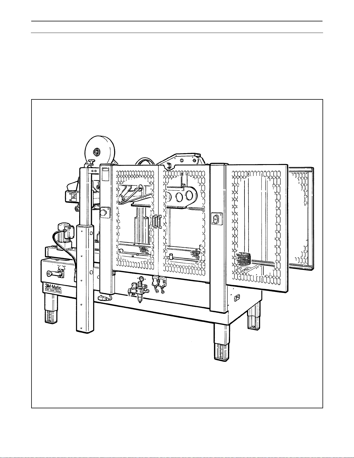
The intended use of the 3M-Matic™ 800af Adjustable Case Sealer with AccuGlide™ II Taping Heads is to
automatically seal the top and bottom center seams of regular slotted containers without the need for an
operator. It will accept filled regular slotted containers from an existing conveyor, fold the top flaps and apply a
"C" clip of Scotch™ brand pressure-sensitive film box sealing tape to the top and bottom center seams of the
box. An integral gate provides the proper spacing of incoming boxes. Infeed conveyor speed must not exceed
0.3 m/s [60 F.P.M.] maximum. The machine has been designed and tested for use with Scotch™ brand
pressure-sensitive film box sealing tape.
3M-Matic™ 800af Adjustable Case Sealer, Type 39600
1
Page 7

Equipment Warranty and Limited Remedy: THE FOLLOWING WARRANTY IS MADE IN LIEU OF ALL
OTHER WARRANTIES, EXPRESS OR IMPLIED, INCLUDING, BUT NOT LIMITED TO, THE IMPLIED
WARRANTY OF MERCHANTABILITY, THE IMPLIED WARRANTY OF FITNESS FOR A PARTICULAR
PURPOSE AND ANY IMPLIED WARRANTY ARISING OUT OF A COURSE OF DEALING, A CUSTOM OR
USAGE OF TRADE:
3M sells its 3M-Matic™ 800af Type 39600 with the following warranties:
1. The drive belts and the taping head knives, springs and rollers will be free from all defects MȎ ninety (90)
days after delivery.
2. All other taping head parts will be free from all defects for three (3) years after delivery.
3. All other parts will be free from all defects for two (2) years after delivery.
If any part is proved to be defective within its warranty period, then the exclusive remedy and 3M’s and seller’s
sole obligation shall be, at 3M’s option, to repair or replace the part, provided the defective part is returned
immediately to 3M’s factory or an authorized service station designated by 3M. A part will be presumed to have
become defective after its warranty period unless the part is received or 3M is notified of the problem no later
than five (5) calendar days after the warranty period. If 3M is unable to repair or replace the part within a
reasonable time, then 3M at its option, will replace the equipment or refund the purchase price. 3M shall have
no obligation to provide or pay for the labor required to install the repaired or replacement part. 3M shall have
no obligation to repair or replace (1) those parts failing due to operator misuse, carelessness, or due to any
accidental cause other than equipment failure, or (2) parts failing due to non-lubrication, inadequate cleaning,
improper operating environment, improper utilities or operator error.
Limitation of Liability: 3M and seller shall not be liable for direct, indirect, special, incidental or consequential
damages based upon breach of warranty, breach of contract, negligence, strict liability or any other legal theory.
The foregoing Equipment Warranty and Limited Remedy and Limitation of Liability may be changed only by a
written agreement signed by authorized officers of 3M and seller.
Contents – 800af Adjustable Case Sealer
(1) 800af Adjustable Case Sealer, Type 39600
(1) Tool/Spare Parts Kit, P/N 78-8060-8476-6
(1) Instruction and Parts Manual
ScotchTM, AccuGlideTM, and 3M-MaticTM are Trademarks of 3M, St. Paul, Minnesota 55144-1000
2
Page 8
Important Safeguards
This safety alert symbol identifies
important messages in this manual.
READ AND UNDERSTAND THEM BEFORE
INSTALLING OR OPERATING THIS
EQUIPMENT.
Important – In the event the following safety
labels are damaged or destroyed, they must be
replaced to ensure operator safety. A label
kit, part number 78-8113-6881-6 is available as
a stock item or individual labels can be ordered.
See Parts Illustration/List, Section I, pages 86 &
87.
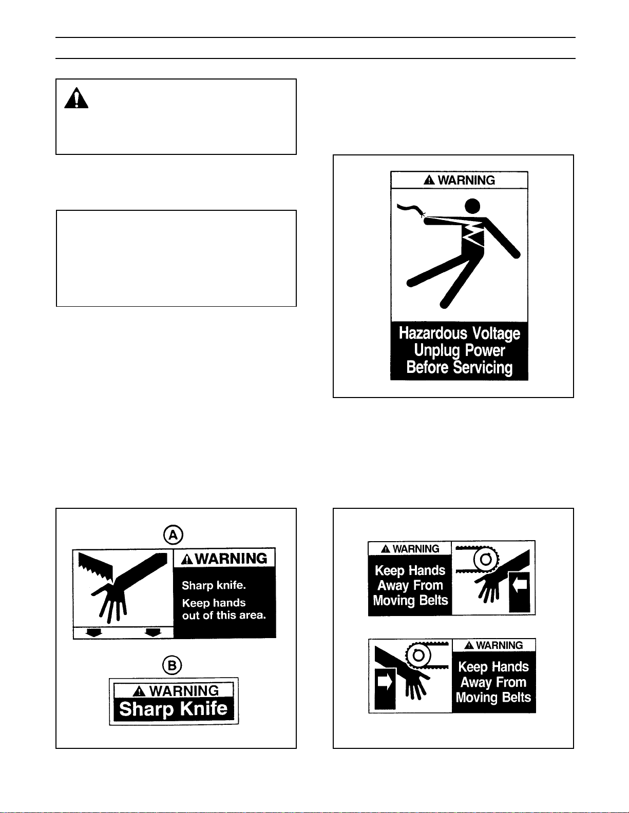
The "Warning – Hazardous Voltage" label, shown
in Figure 1-2, is attached to the cover of the
electrical control box on the lower right side of the
machine frame. The label warns service personnel
to unplug the power supply before attempting any
service work on the case sealer.
The "Warning – Sharp Knife" label (A), shown in
Figure 1-1, is attached to both sides of the upper
frame at the location of the cut-off knife on the upper
taping heads. The "Warning – Sharp Knife" label
(B), shown in Figure 1-1, is attached to the orange
cut-off knife guard on both taping heads. The labels
warn operators and service personnel of the very
sharp knife used to cut the tape at the end of the
tape application.
Figure 1-2 – Electrical Warning Label
The "Warning – Keep Hands Away From Moving
Belts" labels, shown in Figure 1-3, are located on
the infeed end of the machine bed on each side.
The labels warn operators to keep hands away from
this area when drive belts are running.
Figure 1-1 – Knife Warning Label
Figure 1-3 – Box Drive Belt Warning Label
3
Page 9
Important Safeguards (Continued)
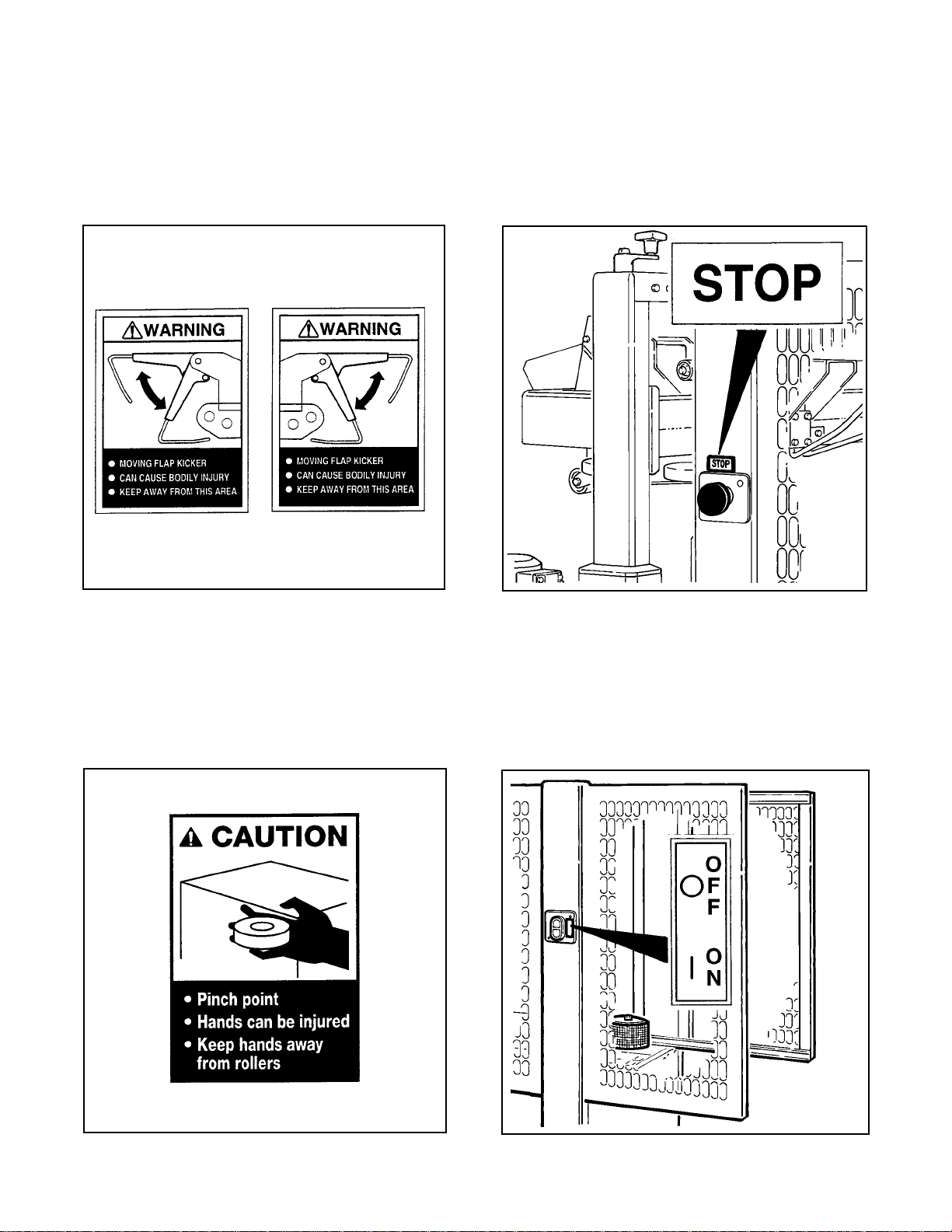
The "Warning – Moving Flap Kicker" labels,
shown in Figure 1-4, are attached to the machine
guards on the infeed end, close to the top. These
labels remind the operator and service personnel to
keep away from flap kicker when machine is running.
Two emergency stop switches are located, one on
each side of the machine, on the guard at the center
of the machine. The "Stop" label, shown in Figure
1-6, is located near these switches and remind
operators and other personnel of the function of
these switches.
Figure 1-4 – Moving Flap Kicker
The "Caution – Pinch Point" label, shown in
Figure 1-5, is attached to the back side of the
compression roller brackets on both sides of the
machine. The label reminds operator to keep hands
away from compression rollers when machine is
running.
Figure 1-6 – Stop and On/Off Labels
The "On/Off" label, shown in Figure 1-7, is located
next to the electrical on/off switch on the guard (left
side) at the infeed end of the machine. The label
reminds operators of the function of this switch.
Figure 1-5 – Pinch Point Caution Label Figure 1-7 – On/Off Label
4
Page 10
Important Safeguards (Continued)
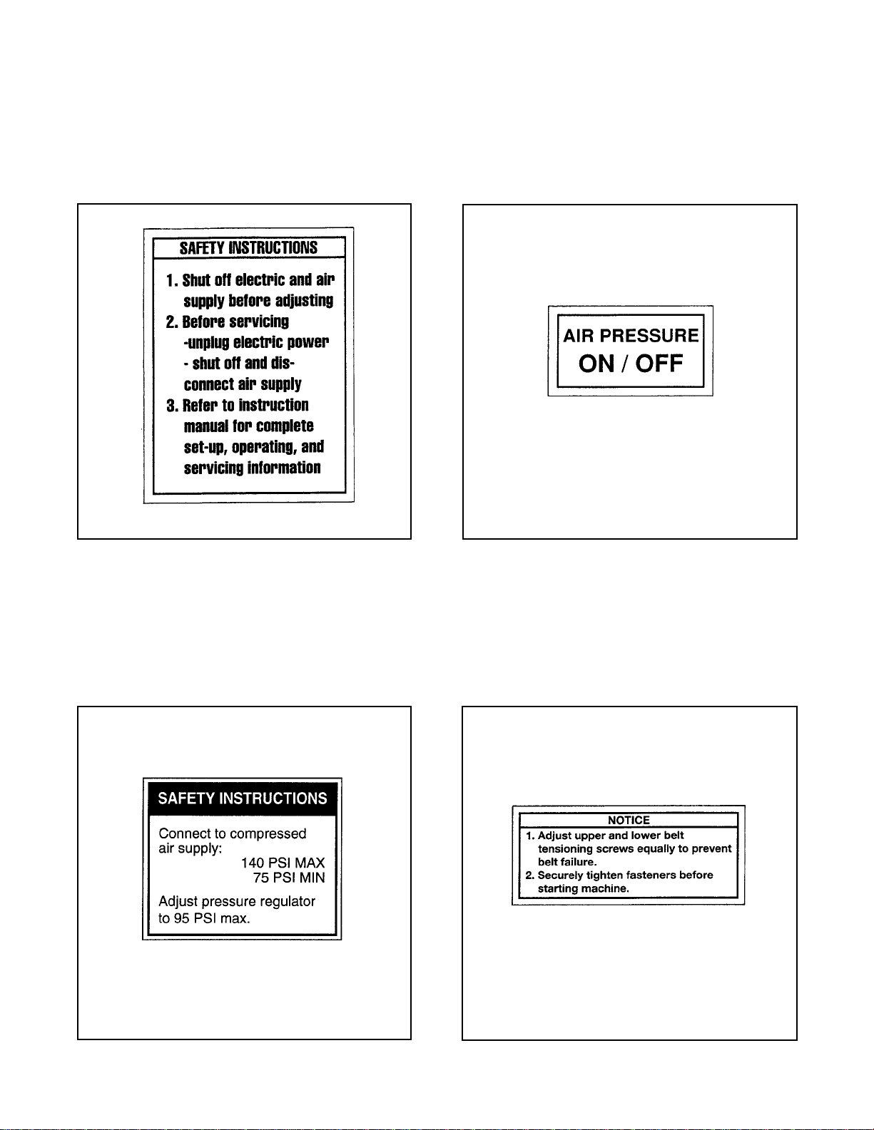
The "Safety Instructions" label, shown in Figure
1-8, is attached to the top of both side guards near
the center of the machine. The label provides
convenient safeguard instructions for the operator
and service personnel.
The "On/Off" label, shown in Figure 1-10, is
attached to the frame above the On/Off valve and
reminds operators of the location of this valve and
its function.
Figure 1-8 – Safety Instructions Label
The "Safety Instructions" label, shown in
Figure 1-9, is attached to the frame above the air
valve/regulator and reminds operator of the correct
air pressure to use.
Figure 1-10 – On/Off Label
Two "Operating Notice" labels, shown in
Figure 1-11, are located on the top, infeed end of
both drive belt assemblies. The labels remind
operators of correct belt adjustment procedures.
Figure 1-9 – Safety Instructions
Figure 1-11 – Operating Notice Label
5
Page 11
Important Safeguards (Continued)
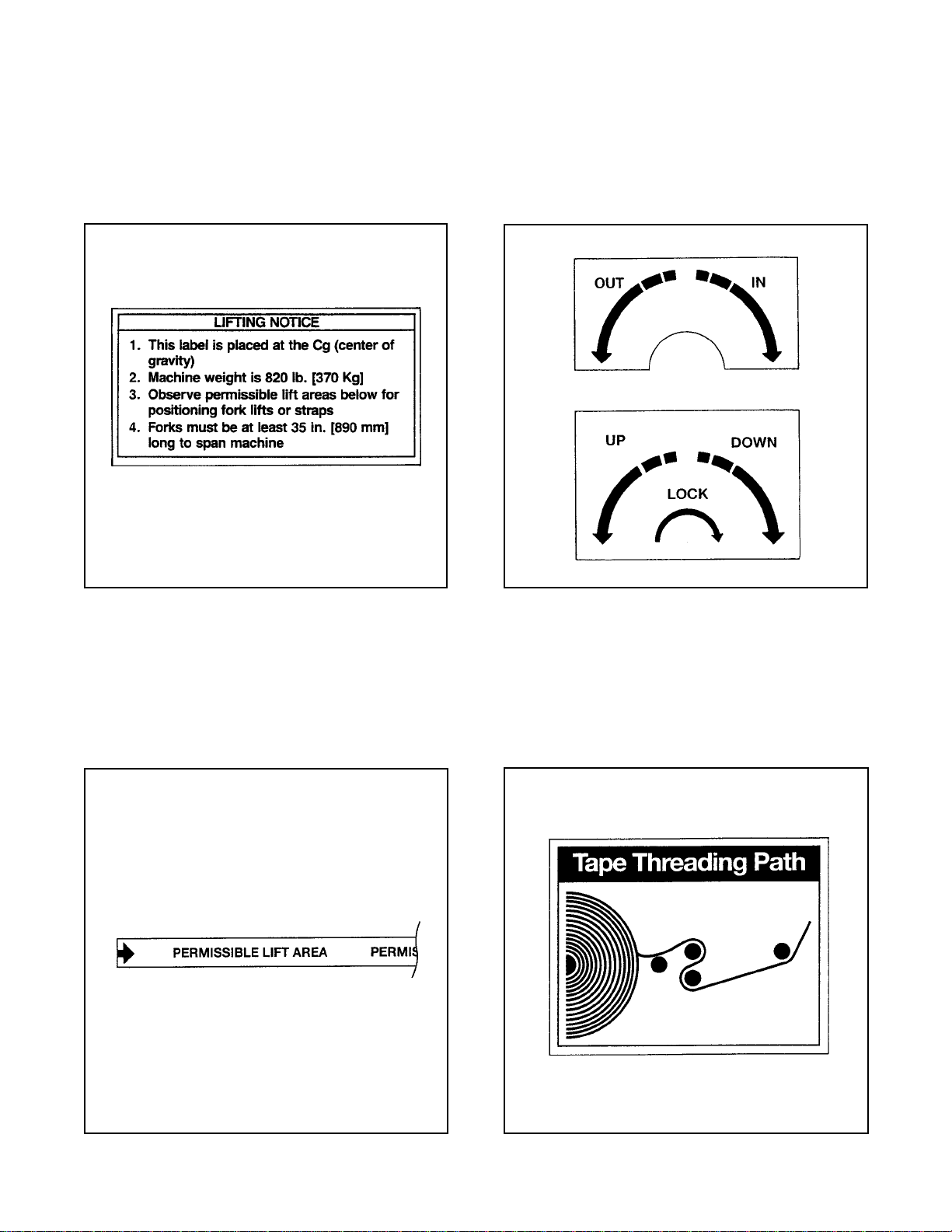
The "Lifting Notice" label, shown in Figure 1-12, is
attached to the left side of the machine frame close
to the air pressure regulator. This label reminds
service personnel of the center-of-gravity and weight
of the machine if machine must be lifted and moved.
The "Up/Down/Lock" and "In/Out" labels shown in
Figure 1-14, are attached next to the corresponding
height and width adjustment cranks. These labels
remind operators of direction to turn adjustment
cranks to match box height/width.
Figure 1-12 – Lifting Notice Label
Two "Permissible Lift Area" labels shown in
Figure 1-13, are attached, two on each side of
machine, at the lower edge of the frame. These
labels remind service personnel where to place
forks if machine is lifted and moved with forklift
truck.
Figure 1-14 – Up/Down/Lock and In/Out Labels
The "Tape Threading" label, shown in Figure 1-15,
is attached to the lower frame, at the infeed end.
This label is a quick reference for tape threading
when lower tape roll is mounted in outboard
position.
Figure 1-13 – Permissible Lift Area Label
Figure 1-15 – Tape Threading Label
6
Page 12
Specifications
1. Power Requirements:
Electrical – 115 VAC, 60 Hz, 3.8 Amp (440 watts)
Pneumatic – 6.5 bar gauge pressure [95 PSIG], 2.5 SCFM
75 liter/minute @ 21° C., 1.01 bar maximum at maximum cycle rate.
A pressure regulator/filter is included.
The machine is equipped with two 1/6 HP gearmotors and comes with an 2.4 m [8 foot] standard neoprene
covered power cord and a grounded plug. Contact your 3M Representative for power requirements not listed
above.
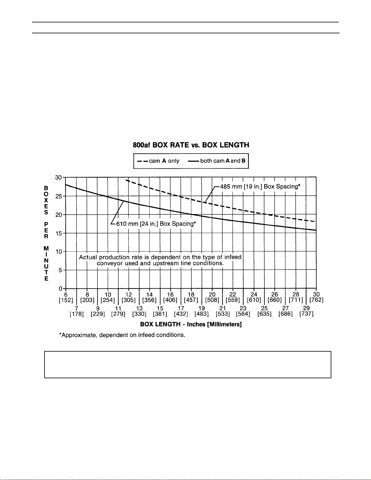
2. Operating Rate:
Note: Machine is shipped with both cams (A and B) installed. To obtain production rate shown
with dotted line (cam A only), cam B must be removed. See "Adjustments – Gate Operation",
page 29.
(continued)
7
Page 13

Specifications (Continued)
3. Operating Conditions:
Use in dry, relatively clean environments at 5o to 40o C [40o to 105o F] with clean, dry boxes.
Note – Machine should not be washed down or subjected to conditions causing moisture condensation
on components.
4. Tape:
ScotchTM brand pressure-sensitive film box sealing tapes.
5. Tape Width:
36 mm [1-1/2 inch] minimum to 48 mm [2 inch] maximum
6. Tape Roll Diameter:
Up to 405 mm [16 inch] maximum on a 76.2 mm [3 inch] diameter core.
(Accommodates all system roll lengths of Scotch
TM
brand film tapes.)
7. Tape Application Leg Length – Standard:
70 mm ±6 mm [2-3/4 inch ±1/4 inch]
Tape Application Leg Length – Optional:
50 mm ±6 mm [2 inch ±1/4 inch]
(See "Special Set-Up Procedure" – Changing the Tape Leg Length", page 34.)
8. Box Board:
Style – regular slotted containers – RSC
125 to 275 P.S.I. bursting test, single wall B or C flute.
IMPORTANT SAFEGUARD
IMPORTANT SAFEGUARD
(continued)
8
Page 14

Specifications (Continued)
9. Box Weight and Size Capacities:
A. Box Weight, filled – contents must support flaps.
Minimum – weight must be sufficient to hold carton on the conveyor bed with bottom flaps fully closed
or 1.4 kg [3 lb.] minimum.
Maximum – 40 kg [85 lb.]
B. Box Size:
Minimum: Length – 150 mm [6 inches] Maximum: Length – 760 mm [30 inches]
Width – 120 mm [4-3/4 inches] Width – 545 mm [21-1/2 inches]
Height – 120 mm [4-3/4 inches]*
* Boxes lower than 165 mm [6-1/2 inches] and wider than 320 mm [12-1/2 inches] require removal of
compression rollers.
With taping heads adjusted to apply 50 mm [2 inch] tape legs, minimum box height is 95 mm
[3-3/4 inches] with box widths greater than 195 mm[7-3/4 inches]. See "Special Set-Up Procedure Changing the Tape Leg Length", page 34.
** With columns adjusted to upper position, maximum box height increase to 725 mm [28-1/2 inches] and
minimum box height increases to 225 mm [8-3/4 inches]. See "Special Set-Up Procedure – Outer
Column Re-Positioning", page 35.
Height – 620 mm [24-1/2 inches]**
Note – The case sealer is designed to accommodate most boxes complying with the 1976 FBA and
PMMI*** voluntary standard "Tolerances for Top Opening" regular slotted containers (RSC).
Two of the requirements of the standard are the following:
1. The box length is not more than twice the box width.
2. The box length is not more than four times the box depth.
In addition, the box score lines must be sufficient to facilitate automatic flap folding. Certain
environmental conditions, such as high humidity, can be detrimental to automatic flap folding.
***Fibre Box Association, Packaging Machinery Manufacturer's Association
DETERMINE THE BOX LIMITATIONS BY COMPLETING THIS FORMULA:
BOX LENGTH IN DIRECTION OF SEAL MUST BE GREATER THAN .6
BOX HEIGHT
If any of the above criteria are not met boxes should be test run to assure proper machine performance.
(continued)
9
Page 15
Specifications (Continued)
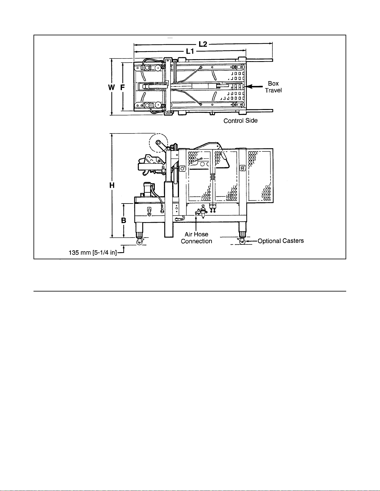
10. Machine Dimensions:
WL1 L2 H B F
Minimum
mm 985 1920 2375 1575 610 825
[inches] [38-3/4] [75-5/8] [93-7/16] [62] [24] [32-1/2]
Maximum
mm 985 1920 2375 2185 890 825
[inches] [38-3/4] [75-5/8] [93-7/16] [86] [35] [32-1/2]
Weight – 410 kg [900 lbs.] crated (approximate)
370 kg [820 lbs.] uncrated (approximate)
11. Set-Up Recommendations:
• Machine must be level.
• Customer supplied infeed and exit conveyors (if used) should provide straight and level box entry and exit.
• Exit conveyors (powered or gravity) must convey sealed boxes away from machine.
10
Page 16

Installation and Set-Up
Receiving And Handling
After the machine has been uncrated, examine the case sealer for damage that might have occurred during
transit. If damage is evident, file a damage claim immediately with the transportation company and also
notify your 3M Representative.
Machine Set-Up
It is recommended that the case sealer be set-up and operated with product before placing it in the production
line. This approach will allow your thorough review and familiarization with the 800af before subjecting it and
operating personnel to a production situation where time for set-up, adjustments, and operator training usually
becomes limited.
The following instructions are presented in the order recommended for setting up and installing the case sealer.
Following them step by step will result in an installation in your production line that best utilizes the many features
built into the case sealer. Refer to Figure 3-1 and 3-2 to identify the various components and controls of the
machine.
For future reference, record machine serial number on front cover of this instruction manual in the space
provided.
IMPORTANT – Read "Warnings" on page 18 before attempting to set-up the case sealer for operation.
1. Follow "Unpacking Instructions" label attached to corrugated packing cover.
2. Use appropriate material handling equipment to remove the machine from the pallet and move it into position.
Whenever the machine is lifted with a fork truck, insure that the forks span completely across the machine
frame and do not contact any wiring or mechanism under the machine frame. In some cases the lower taping
head may need to be removed to avoid damage.
CAUTION – Machine weighs approximately 370 kg [820 lbs] uncrated.
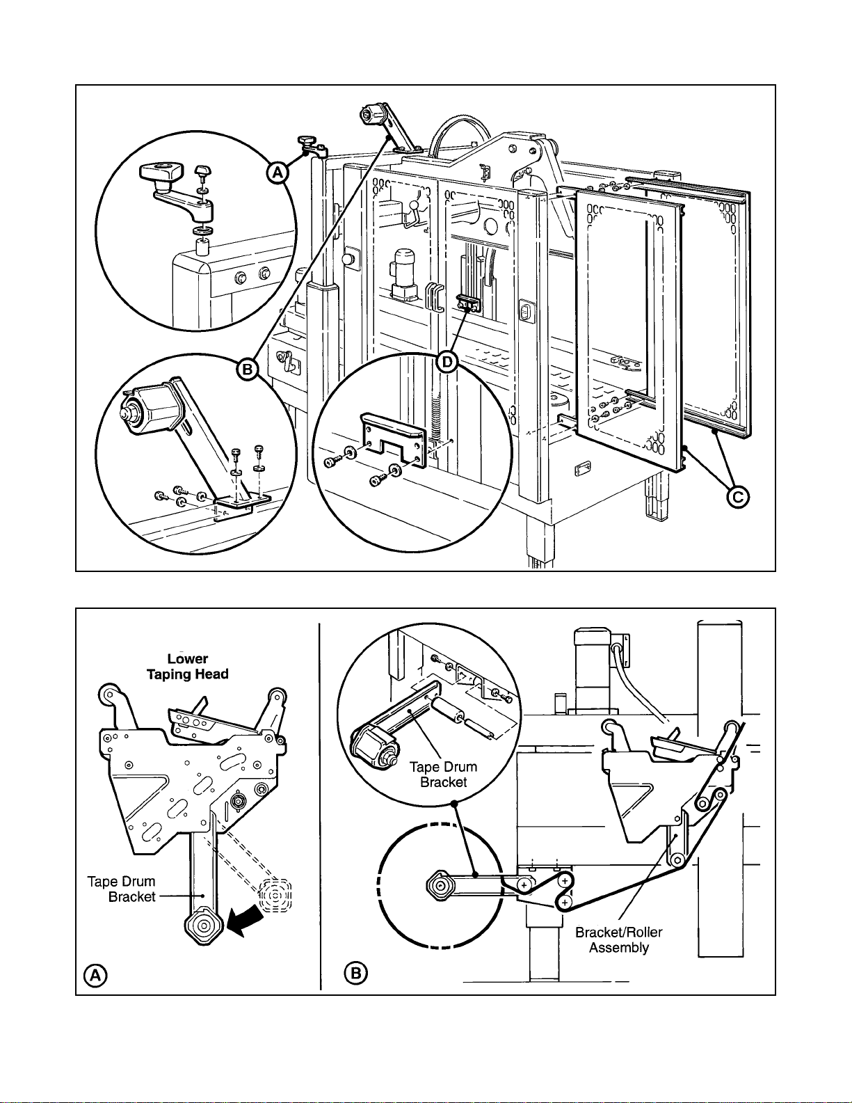
2. Remove and discard cable ties on upper head assembly.
3. Install the crank handle on the top of the left column, as shown in Figure 2-1A.
4. Install upper tape drum bracket on the top cross bar, as shown in Figure 2-1B.
5. Install the two infeed end guards. Attach the guards to the infeed end vertical masts, as shown in
Figure 2-1C.
6. Raise upper head assembly (turn crank handle counterclockwise). Install the machine stops (from parts bag).
Mount these stops as shown in Figure 2-1D using lowest hole position on brackets. The upper hole position
in the stops should only be used when the heads are adjusted to apply 50 mm [2 inch] tape legs.
7. The lower tape drum bracket assembly is mounted on the lower head in the standard position. Ensure that
the bracket assembly is mounted straight down, as shown in Figure 2-2A. The tape drum bracket assembly
can be pivoted to provide clearance or for retrofit in certain cases.
Lower outboard tape roll mounting (alternate position) –
a. Remove lower taping head from machine.
b. Remove existing tape drum bracket from taping head and replace with bracket/roller assembly (shipped
loose), Figure 2-2B. Replace taping head in machine.
c. Install tape drum bracket (removed from taping head) on exit end of machine lower frame as shown in
Figure 2-2B.
11
Page 17
Installation and Set-Up (Continued)
Figure 2-1 – Installation and Set-Up
Figure 2-2 – Lower Tape Drum Bracket Position
12
Page 18
Installation and Set-Up (Continued)
8. Install case sealer in production line. When installing the case sealer, be sure to observe the following
guidelines.
a. Case sealer must be installed level – it is not designed to convey boxes uphill.
b. Infeed conveyor must convey boxes to case sealer at a speed not to exceed 0.30 m/s [60 f/m].
c. Precautions must be taken to prevent excessive box pressure against the case sealer infeed gate.
This will help to prevent damage to the boxes and ensure proper performance.
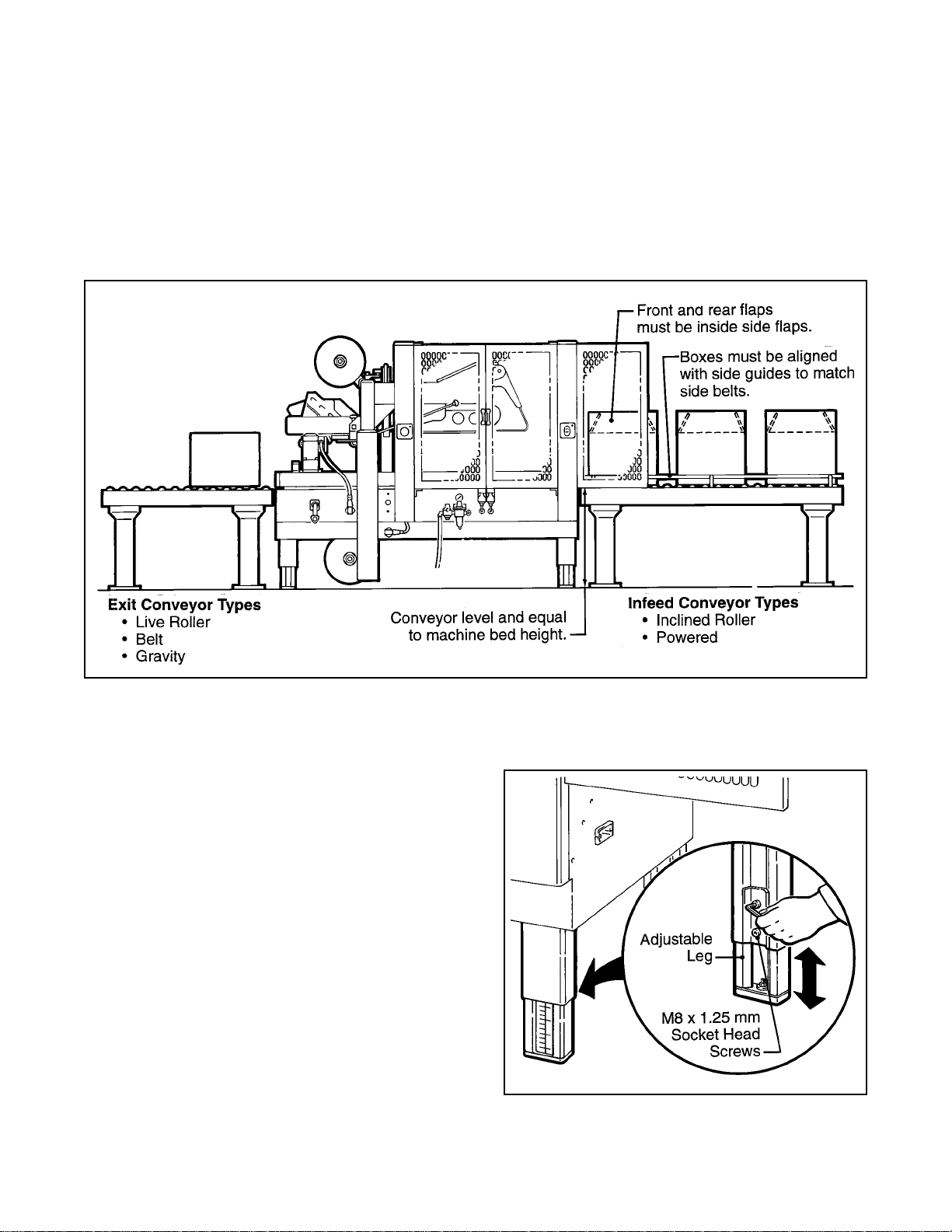
d. Infeed and exit conveyors must provide straight entrance and exit of boxes to/from case sealer and exit
conveyor must positively convey boxes away from machine.
e. Refer to Figure 2-3 for suggested conveyor types that can be used with the case sealer.
Figure 2-3 – Conveyor Systems
9. Adjust case sealer bed height. The adjustable
legs provide different machine bed heights from
610 mm [24 inches] minimum to 890 mm
[35 inches] maximum.
Refer to Figure 2-4 and set the machine bed
height as follows:
a. Block up the machine frame to allow
adequate leg adjustment.
b. Loosen, but do not remove, two M8 x 1.25
mm socket head screws in one leg (use M6
hex key wrench). Adjust the leg length for
the desired machine bed height. Retighten
the two screws to secure the leg. Adjust all
four legs equally.
10. Tape width – the taping heads have been preset to accommodate 72 mm [3 inch] wide tape
rolls. To apply narrower width tapes, refer to
Section II, "Adjustments – Tape Web
Alignment", page 11.
Figure 2-4 – Conveyor Bed Height Adjustment
13
Page 19
Installation and Set-Up (Continued)
11. Box size capacity (height) – at its factory setting, the case sealer handles box sizes up to 620 mm
[24-1/2 inches] maximum height. If larger capacity is needed, the machine can be adjusted to accommodate
up to 725 mm [28-1/2 inches] high boxes. Refer to "Special Set-Up Procedure – Outer Column
Re-Positioning", page 35 for set-up information.
12. Drive Belt Height – drive belt assemblies can be raised 50 mm [2 inches] to provide better conveying of tall
boxes. Refer to "Special Set-Up Procedure – Changing Drive Belt Height", page 33.
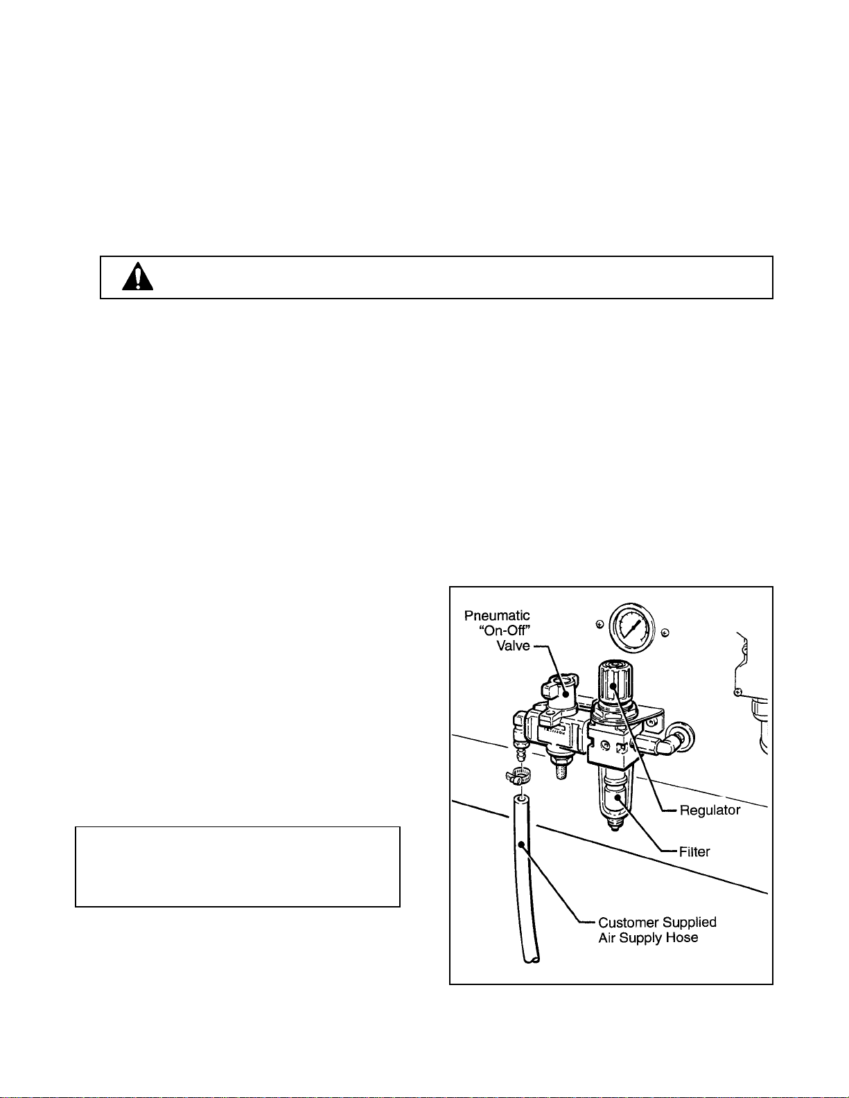
13. Pneumatic connection.
WARNING – USE CARE WHEN WORKING WITH COMPRESSED AIR.
The case sealer requires a 6.5 bar gauge pressure [95 PSIG] 75 liter/min @21°C, 1.01 bar [2.5 SCFM]
compressed air supply. As shown in Figure 2-3 an on/off valve, pressure regulator, and filter are
provided to service the air supply.
The main air supply line should be connected to the on/off valve by means of the barbed fitting and hose
clamp provided on the outer side of the on/off valve as shown in Figure 2-3. The customer supplied air
hose (5/16 inch [8 mm] ID) should be slipped over the barbed fitting and clamped tightly in place.
If another type of connector is desired, the fitting can be removed and replaced with the desired 1/4-18
NPT threaded connector.
Always turn the valve "Off" when air supply line is being connected or disconnected.
14. Electrical connection and controls – the
electrical control box shown in Figure 3-1,
contains the "On/Off" switch with pre-set
breaker and can be located on either side of the
machine frame for operator convenience. A
standard three conductor power cord with plug
is provided at the back of the electrical control
box for 115 Volt, 60 Hz, 3.8 Amp electrical
service. The receptacle providing this service
shall be properly grounded. Before the power
cord is plugged into 115 Volt, 60 Hz outlet,
make sure red "Off" button is depressed and
that all packaging materials and tools are
removed from the machine. Do not plug
electrical cord into outlet until ready to run
machine.
Note – Machines outside the U.S. may be
equipped with 220/240 Volt, 50 Hz systems, or
other electrical requirements compatible with
local practice.
Initial Start-Up of Case Sealer
After completing the "Set-Up" procedure, continue
through ""Operation", pages 15-24 to be sure case
sealer is properly adjusted to run product.
Figure 2-3 – Pneumatic Connection
14
Page 20
Operation
IMPORTANT - Before operating the case sealer, read all the "Important Safeguards", pages 3 - 6 and
"Warnings" on page 18 as well as all of the "Operation" instructions.
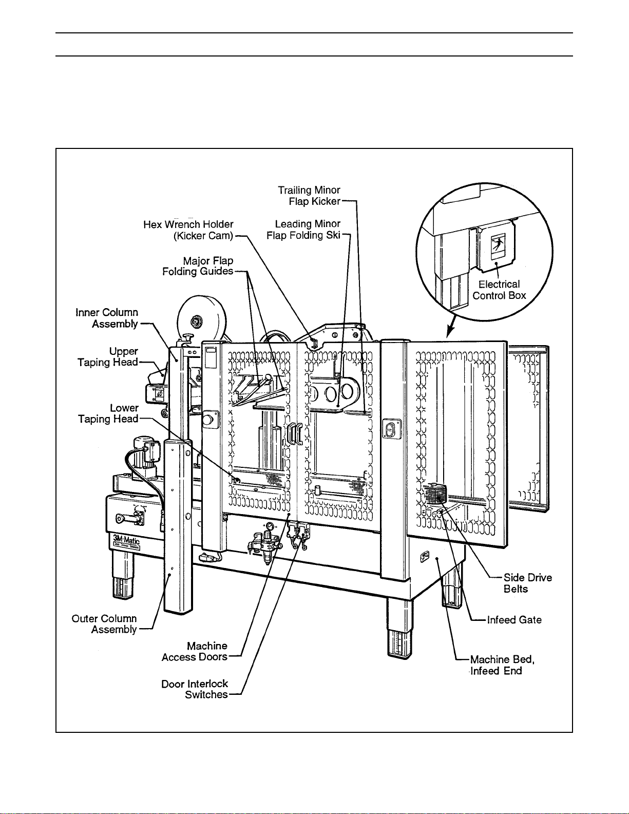
Refer to Figure 3-1 and 3-2 to acquaint yourself with the various components and controls of the 800af case
sealer. Also see Figures 3-1 and 3-2 in Section II for taping head components.
Figure 3-1 – Case Sealer Components
15
Page 21
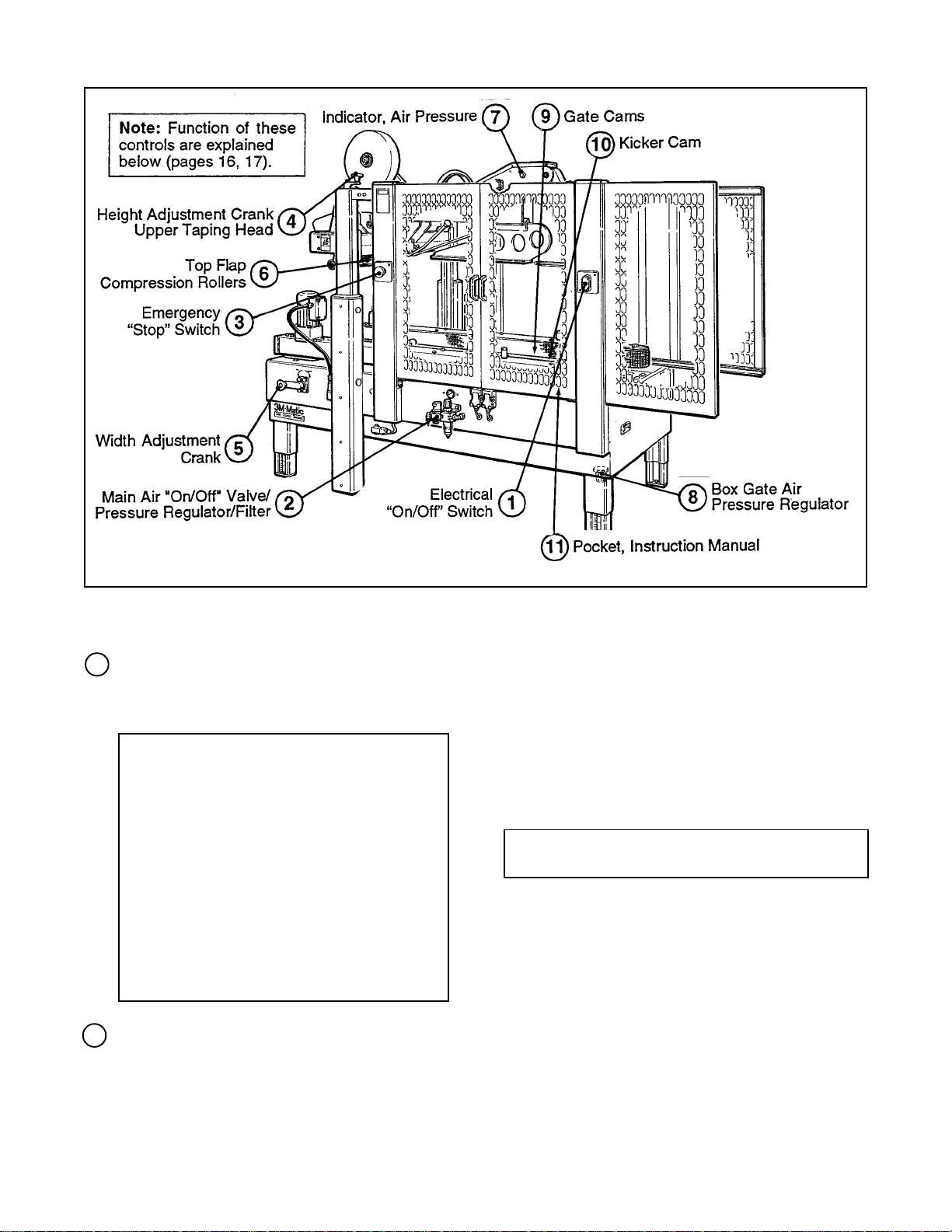
Operation (Continued)
Figure 3-2 – Controls, Valves and Switches
1 Electrical "On/Off" Switch
The box drive belts are turned on and off (off
button is red) with the electrical switch on the
side of the machine guard at the infeed end.
Note – The case sealer has a circuit
breaker located in the electrical enclosure
on the lower right side of the machine
frame. If circuit becomes overloaded and
circuit breaker trips, unplug the machine
electrical cord and determine cause of
overload. After two minutes, remove the
electrical control box cover and reset the
circuit breaker by pressing the "Reset"
button and then the "Start" button on the
circuit breaker. Replace the control box
cover, plug machine electrical cord into
outlet and restart machine by pressing
green "On" button.
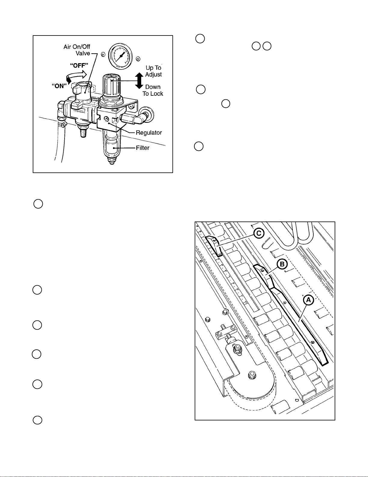
2 Main Air "On/Off" Valve/Pressure
Regulator/Filter – Figure 3-3
This set of pneumatic components controls,
regulates and filters plant air supply to the two
separate control circuits of the case sealer.
"On/Off" Valve – "On" turn to "SUP" – "Off" turn to
"EXH". Note – Turning air supply "Off"
automatically bleeds air pressure from the case
sealer air circuits.
Always turn the air "Off" when machine is not in
use, when servicing the machine, or when
connecting or disconnecting air supply line.
Note – The air valve has provisions for
lockout/tagout according to plant regulations.
Pressure Regulator regulates main air pressure to
the machine to adjust pressure, pull knob up and
turn – push down to lock setting.
Filter removes dirt and moisture from plant air
before it enters the case sealer pneumatic circuits.
If water collects in bottom of bowl, lift up on the
valve on the bottom of bowl to drain.
16
Page 22
Operation (Continued)
Figure 3-3 – "On/Off" Valve/Regulator/Filter
9 Gate Cams Figure 3-4
The gate cams A B control the rate of box
entry into the case sealer. Depending on box
size, gate cams can be adjusted to increase
production rate. See "Adjustments – Gate
Operation", page 29.
10 Kicker Cam Figure 3-4
The minor flap folder, controlled by the kicker
cam C , closes the trailing minor flap on the
box. The kicker cam must be adjusted
according to the length of the box being
sealed. See "Operation", page 20,
Figure 3-8.
11 Pocket, Instruction Manual
A pocket is provided inside the right door for
storage of the machine instruction manual.
Keep the manual in this pocket for the
convenience of machine operators.
3 Emergency "Stop" Switch
The two emergency "Stop" switches are
mounted for operator convenience, on both
sides of the case sealer. Pushing either of
these switches will stop the drive motors/belts
and exhaust air from the flap kicker.
To restart machine, rotate emergency stop
switch (release switch latch) and then restart
machine by pressing green (On) button on side
guard.
4 Height Adjustment Crank, Upper
Taping Head
Raises and lowers upper taping head/flap
folders to accommodate box height.
5 Width Adjustment Crank
Adjusts distance between side drive belts to
accommodate box width.
6 Top Flap Compression Rollers
Rollers adjust to properly maintain box width/
top flap center seam for tape seal.
7 Indicator, Air Pressure
The optical warning indicator, located on the
upper flap folder frame, indicates "Red" when
compressed air circuit is on.
8 Box Gate Air Pressure Regulator
Adjusts lifting force of the box gate depending
on the weight of boxes being sealed.
Figure 3-4 – Gate/Kicker Cams
17
Page 23

Operation (Continued)
WARNINGS
1. Turn electrical and air supply off and disconnect before servicing taping heads or performing
any adjustments or maintenance on the machine. Turn electrical and air supplies off when
machine is not in use.
2. Do not leave machine running unattended.
3. Before turning drive belts on, be sure no tools or other objects are on the machine bed.
4. Keep hands and loose clothing away from moving belts and flap kicker.
5. Keep away from flap kicker. Flap kicker is controlled by air and can be activated (if air supply
is "On") by depressing flap kicker cam. Be sure flap kicker is in the down position before
servicing.
6. Never attempt to remove jammed boxes from the machine while machine is running.
7. Machine access door must be closed when drive belts are running. Do not attempt to override
door interlock switch.
8. Keep hands and clothing away from taping heads when machine is running. A box traveling
through the machine causes taping head rollers to retract when box enters and extend as box
leaves taping head.
9. Both the upper and lower taping heads utilize extremely sharp tape cut-off knives. The knife is
located under the orange knife guard which has the "WARNING – SHARP KNIFE" label. Before
loading tape, refer to Figures 3-1 and 3-2 in Section II to identify the knife location. Keep
hands out of these areas except as necessary to service the taping heads.
10. Failure to comply with these warnings could result in severe personal injury and/or equipment
damage.
Tape Loading/Threading – Upper Taping Head
See Section II, Pages 7 and 8
Tape Loading/Threading – Lower Taping Head
With Tape Drum On Taping Head
See Section II, Pages 7 and 8
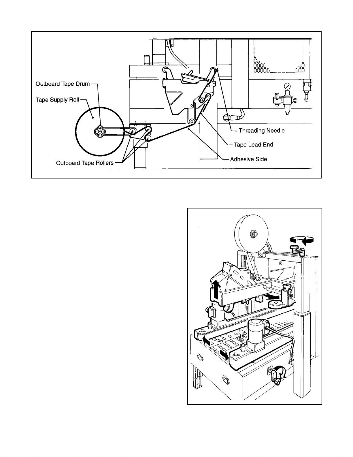
Tape Loading/Threading – Lower Taping Head
With Alternate Outboard Tape Drum
CAUTION – Taping head weighs
approximately 7.2 kg [16 pounds]
without tape. Use proper body
mechanics when removing or installing
taping head.
1. Raise upper taping head high enough to allow
clearance for removing lower taping head.
2. Remove lower taping head from machine bed
and install threading needle as explained in
Section II, page 7.
3. Replace taping head back into machine.
4. Place tape roll on outboard tape drum with
adhesive side down on lead end of tape. (Seat
tape roll fully against back flange of tape drum.)
Thread tape through outboard tape rollers as
shown in Figure 3-5 and adhere tape lead end
to lower end of threading needle.
5. Complete tape threading as explained in
Section II, page 8.
18
Page 24
Operation (Continued)
Figure 3-5 – Tape Threading With Alternate Outboard Tape Drum
Box Size Set-Up
Figure 3-6
Open the side drive belts and raise the upper head
assembly to accommodate the desired box width
and height.
Move the compression rolls as wide as possible.
Figure 3-6 – Box Size Set-Up
19
Page 25
Operation (Continued)
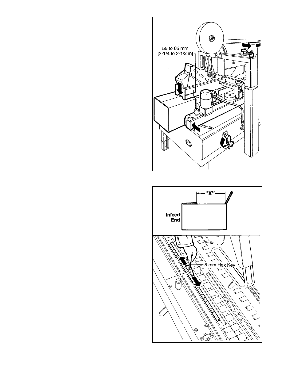
Figure 3-7
Place a product filled box 55 to 65 mm [2-1/4 to
2-1/2 inches] into the exit end of the machine with
the top flaps folded as shown.
Crank the upper head down until is just contacts the
top of the box.
Crank the side drive belts in until the belts firmly grip
the box.
Figure 3-8
Set Kicker cam relative to length of box being
sealed. Measure the distance "X" as shown and set
the cam to the same dimension measured on the
box. (This dimension provides a good starting point
for setting the kicker cam.)
Note: 5 mm hex key wrench is supplied with
machine and should be kept in wrench holder on
side of upper frame. See Figure 3-1.
Figure 3-7 – Box Size Set-Up
Figure 3-8 – Box Size Set-Up
20
Page 26
Operation (Continued)
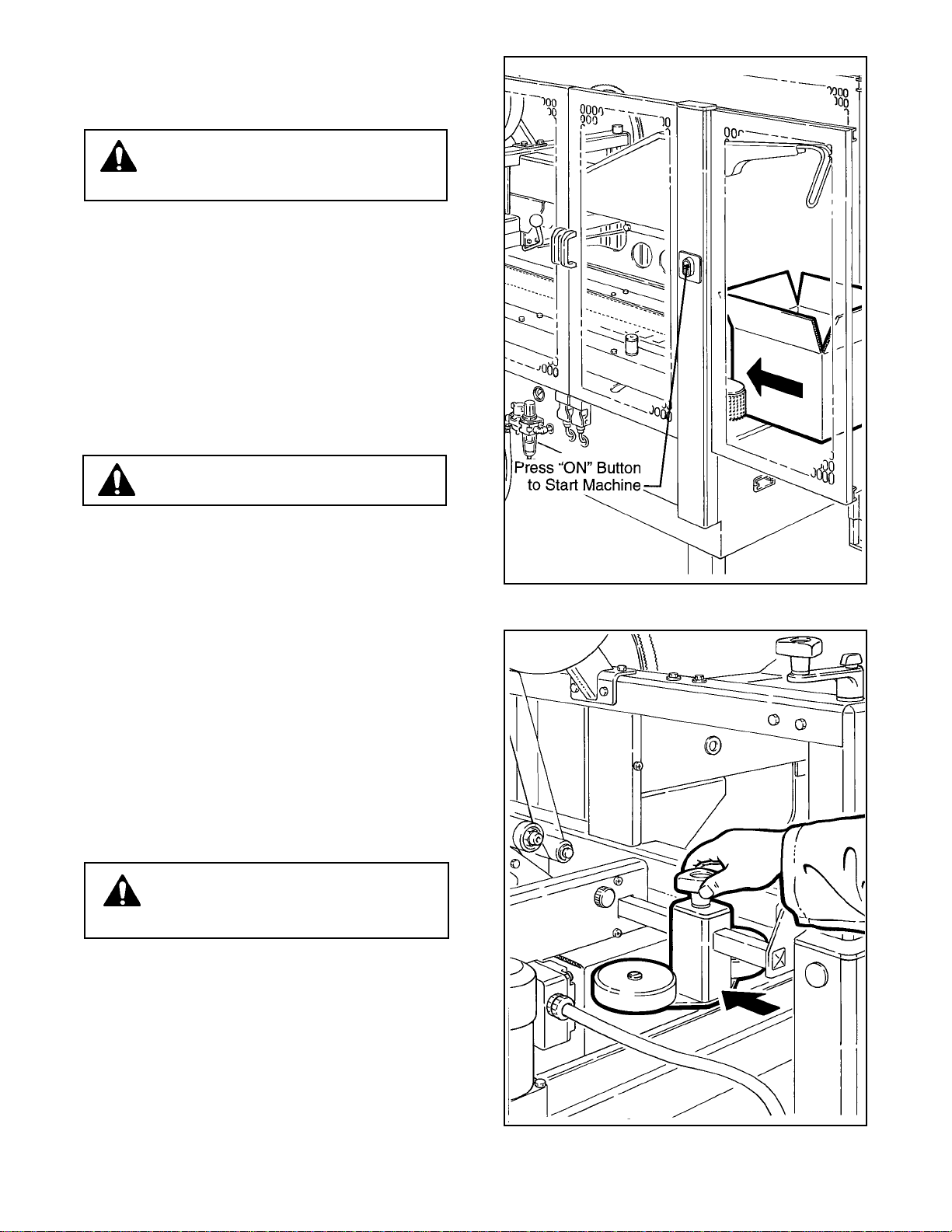
Figure 3-9
WARNING – Be sure all packaging
materials and tools are removed from
the machine before operating
Turn air On/Off valve to the "On" (SUP) position.
Press electrical "On" button to start drive belts.
Place box at infeed end of machine and push into
machine until it is taken away by drive belts.
CAUTION – Keep hands away from
drive belts when feeding boxes.
Figure 3-10
Adjust compression rollers. Run box through
machine and stop when adjacent to compression
rollers. Move compression rollers in to press box top
flaps firmly together. Restart machine to exit box.
WARNING – Keep hands away from
compression rollers when box is
passing through machine to avoid injury.
Figure 3-9 – Box Size Set-Up
Figure 3-10 – Box Size Set-Up
21
Page 27
Operation (Continued)
Figure 3-11
Run several test boxes through the machine, and
observe the flap kicking action. Adjust the kicker
cam so the kicker "kicks" earlier or later as required
(refer to figure 3-8). In general, it is better to set the
kicker to "kick" early because it contacts the flap
higher above the score-line which results in more
reliable flap folding.
WARNING – Keep hands away from
drive belts and flap kicker when
feeding boxes to the machine.
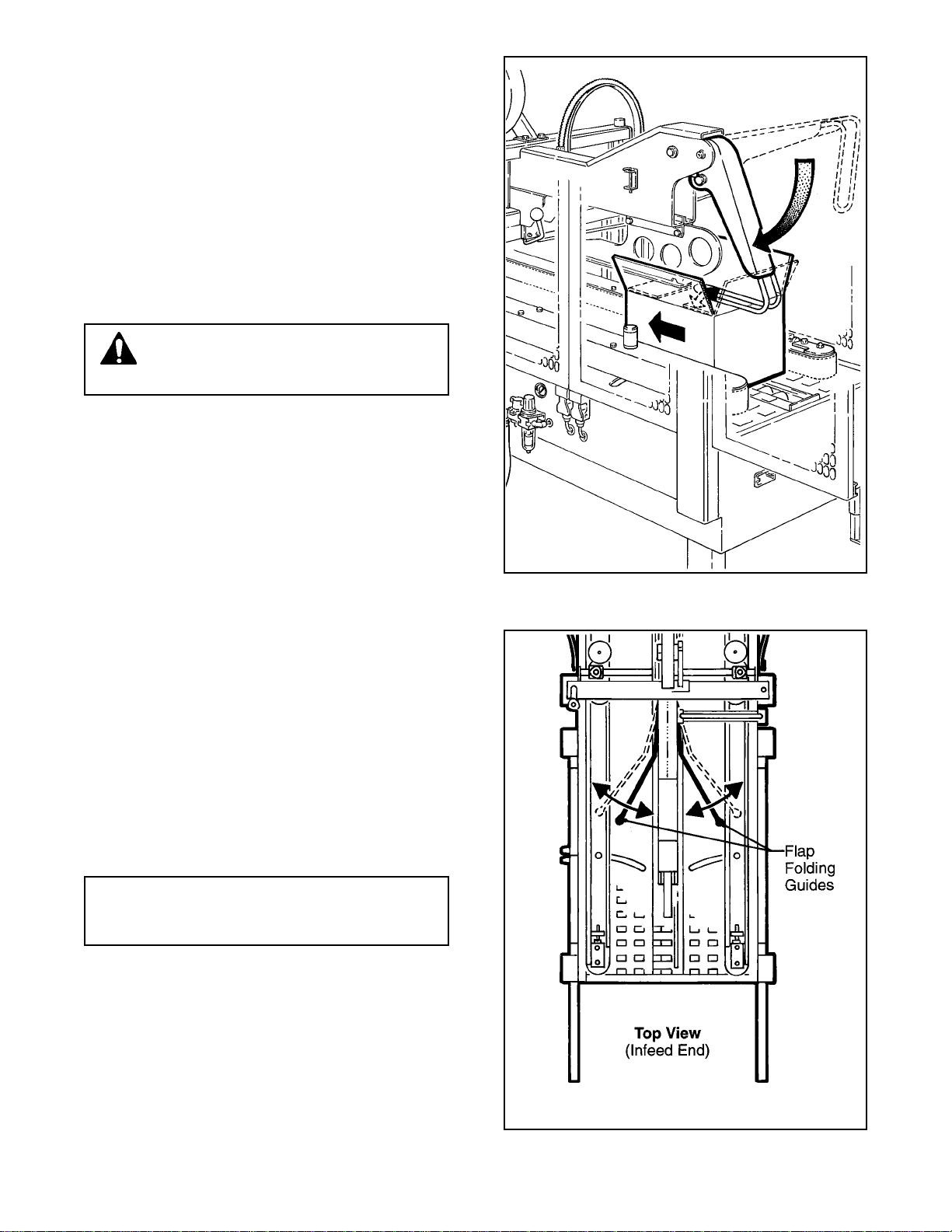
Figure 3-12
The upper side flap folding guides can be adjusted
in or out to accommodate the width of the box. For
optimum performance, the side flap folding guides
should be adjusted to the narrowest position which
allows them to catch any side flaps that may be
bent outward past vertical.
Note – Box flaps should not be bent outward
past vertical more than 15° when entering
case sealer.
Figure 3-11 – Box Size Set-Up
Figure 3-12 – Box Size Set-Up
22
Page 28
Operation (Continued)
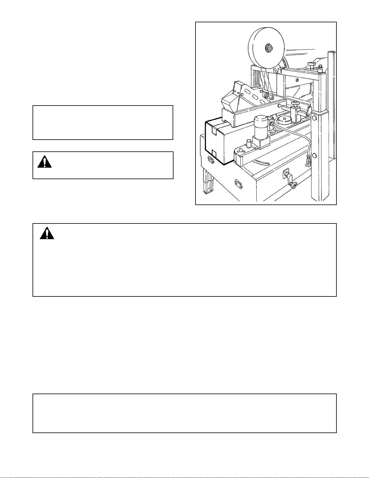
Figure 3-13
If the box is hard to move under the top head or is
crushed, raise the top head slightly.
If the box movement is jerky or stops under the top
head, move the side drive belts in slightly to add
more pressure between the box and drive belts.
Note: Upper head has unique feature for
overstuffed boxes. The head will raise up to
13 mm [1/2 inch] to compensate for this type of
condition.
CAUTION – If drive belts are allowed to
slip on box, excessive belt wear will
occur.
Box Sealing
Figure 3-13 – Box Size Set-Up
WARNINGS
1. Remove tools or other objects from machine bed before starting machine.
2. Keep hands and loose clothing away from moving belts, flap kicker and flap kicker cam.
3. When feeding boxes to the machine by hand, push box in from end only – DO NOT PUSH
WITH HANDS ON ANY CORNER OF THE BOX.
5. Never attempt to remove jammed boxes from the machine while machine is running.
See "Box Jams", page 24.
1. Connect electrical and air supplies.
2. Turn main air valve "On" and adjust air regulator if pressure does not read 5 bar gauge pressure [70 PSIG].
3. Press electrical "On" button to start drive belts.
4. Continually feed boxes to case sealer, case sealer will automatically space entrance of boxes to machine.
5. Turn electrical and air supplies "Off" when machine is not in use.
6. Reload and thread tape as necessary.
7. Be sure machine is cleaned and lubricated according to recommendations in "Maintenance" section of this
manual.
Notes:
1. Box drive motors are designed to run at a moderate temperature of 40° C [104° F]. In some cases they
may feel hot to the touch.
2. Adjustment of the machine or taping heads are described in the "Adjustment" section of this manual.
23
Page 29

Operation (Continued)
Box Jams
If a box is improperly fabricated or filled, if the machine is mis-adjusted for the box being run, or if boxes enter
the machine incorrectly, a box jam may occur. To clear a box jam, follow these steps:
1. Determine cause of box jam so corrective action can be taken to prevent reoccurrence.
2. Turn off machine.
WARNINGS
1. Turn off and disconnect air and electrical supplies before attempting to remove jammed
box or serious injury could occur.
2. Wait for flap kicker to reach down position as shown in Figure 3-11, to avoid being hit or
startled by its movement.
3. Crank upper head up and/or drive belts out until box is free.
4. Carefully pull box out of machine.
WARNINGS
1. Keep hands away from upper and lower taping head cut-off knife as knife is extremely
sharp and can cause severe injury.
2. When reaching into the machine to remove a jammed box, use proper posture to
prevent back or other injuries.
5. Readjust upper head and drive belts according to "Machine Adjustment for Box Size" instructions on pages
19 - 23.
6. Connect air and electrical supplies.
7. Turn machine "On" only when it is safe to do so!
24
Page 30

Maintenance
The case sealer been designed for long, trouble
free service. The machine will perform best when it
receives routine maintenance and cleaning.
Machine components that fail or wear excessively
should be promptly repaired or replaced to prevent
damage to other portions of the machine or to the
product.
WARNING – Turn air and electrical
supplies off and disconnect before
beginning maintenance. Failure to comply
with this warning could result in severe
personal injury or equipment damage.
Cleaning
Note – Never attempt to remove dirt by blowing
it out with compressed air. This can cause the
dirt to be blown inside the motor and onto
sliding surfaces which may cause premature
equipment wear. Never wash down or subject
equipment to conditions causing moisture
condensation on components. Serious
equipment damage could result.
Regular slotted containers produce a great deal of
dust and paper chips when processed or handled in
equipment. If this dust is allowed to build-up on
machine components, it can cause component
wear and overheating of drive motor. The dust
build-up can best be removed from the machine by
a shop vacuum. Depending on the number and
type of boxes sealed in the case sealer, this
cleaning should be done approximately once per
month. If the boxes sealed are dirty, or if the
environment in which the machine operates is
dusty, cleaning on a more frequent basis may be
necessary. Excessive dirt build-up that cannot be
removed by vacuuming should be wiped off with a
damp cloth.
Lubrication
Most of the machine bearings, including the drive
motor, are permanently lubricated and sealed and
do not require additional lubricant.
Figure 4-1 illustrates the areas of the case sealer
that require lubrication. Lubricate points indicated
by arrows ( ) with SAE #30 non-detergent oil
and points indicated by arrows ( ) with a small
amount of multi-purpose grease.
Note – Wipe off excess oil and grease. It will
attract dust and dirt which can cause premature
equipment wear and jamming. Take care that
oil and grease are not left on the surface of
rollers around which tape is threaded, as it can
contaminate the tape's adhesive.
TAPING HEAD LUBRICATION – See Section II,
""Maintenance – Lubrication", page 10.
Figure 4-1 – Lubrication Points, Frame
25
Page 31

Maintenance (Continued)
WARNING – Turn air and electrical supplies off and disconnect before beginning maintenance.
Failure to comply with this warning could result in severe personal injury or equipment
damage.
Drive Belt Replacement/Tension Adjustment
Note – 3M recommends the replacement of drive belts in pairs, especially if belts are unevenly worn.
REPLACEMENT – STEPS 1-11
TENSION ADJUSTMENT – STEPS 1, 2, 4-6, 10 & 11
Figure 4-2
1. Raise upper taping head to its fully raised position.
2. Disconnect motor plug (A).
3. Remove and retain the six screws (B) and side cover (C).
4. Remove and retain screws (D), cap washers (E) and spacers (F) from the front and rear arm assembly
pivots.
5. Lift belt assembly (G) up and off arm assembly pivots.
Note – Keep motor in vertical position to prevent gear oil from leaking out of motor.
Figure 4-2 – Drive Belt Replacement
Figure 4-3
6. Loosen, but do not remove lock nuts (H) on both the upper and lower belt tension assemblies.
7. Turn belt adjustment screws (J) clockwise to end of adjustment on both upper and lower tension assemblies.
8. Locate belt lacing (joint) by turning belt manually. Remove splicing with pliers. Remove and discard belt.
26
Page 32

Maintenance (Continued)
Figure 4-3 – Drive Belt Replacement/Tension Adjustment
9. Important – Before installing new drive belt, check belt inside surface for drive direction arrows and install
belt accordingly. If no arrows are shown, belt may be installed either way.
Install new belt around drive rollers and insert splicing pin. Pin must not extend beyond edge of belt.
10. Set drive belt tension – turn adjustment screws (J) equally on both upper and lower tension assemblies.
Turn screws clockwise to reduce belt tension, counterclockwise to increase tension.
Use force gauge to pull belt outward one inch [25 mm] at midspan, as shown in Figure 4-4, with a moderate
pulling force of 7 lbs. [3.5 kg]. Tighten lock nuts (H) on both tension assemblies to secure tension setting.
11. Assembly is reverse of disassembly.
Figure 4-4 – Drive Belt Tension Adjustment (Top View)
27
Page 33

Maintenance (Continued)
WARNING – Turn air and electrical supplies off and disconnect before beginning
maintenance. Failure to comply with this warning could result in severe personal injury or
equipment damage.
Air Line Filter – Figure 4-5
Periodically check the air line filter to drain water
and clean as necessary. Do not allow water to go
above the filter element.
Circuit Breaker
The case sealer is equipped with a circuit breaker
which trips if the motors are overloaded. Located
inside the electrical control box on the side of the
machine, the circuit breaker has been pre-set at
2.2 Amps and requires no further maintenance.
WARNING – The following procedure
must be performed by trained service
personnel because of the high voltage
electrical hazard within the control box.
If circuit is overloaded and circuit breaker trips,
unplug machine from electrical power:
1. Determine cause of overload and correct.
2. Remove electrical enclosure cover.
3. Press the red "Reset" button and then the
green "Start" button.
4. Replace cover.
5. Plug in machine. Wait two minutes.
6. Press machine "On" button, on the side
guard, to resume case sealing.
Knife Replacement, Taping Head
See Section II, "Maintenance – Blade (Knife)
Replacement", page 9.
Figure 4-5 – Air Line Filter
28
Page 34

Adjustments
WARNING – Turn air and electrical
supplies off and disconnect before
beginning adjustments. Failure to comply
with this warning could result in severe
personal injury or equipment damage.
Gate Operation
Figure 5-1
A – Permanent gate cam
B – Removable gate cam
C – Kicker cam
The 800af is shipped with both gate cams A and B
installed. With both cams the entire range of box
lengths can be run (150-760 mm [6-30 inches]).
However if only boxes longer than 305 mm [12
inches] will be run, cam B can be removed to
increase the production rate. Refer to the box rate
chart in specification section.
Drive Belt Tension
Belt tension must be adequate to positively move
boxes through the machine and belts should run
fully on the surface of the pulleys at each end of the
frame. The idler pulleys on the infeed end are
positioned by tension adjustment screws. To
adjust tension, see "Maintenance – Drive Belt
Replacement/Tension Adjustment", page 26.
Taping Head Adjustments – Refer to Section II
TAPE WEB ALIGNMENT – Section II, Page 11
TAPE DRUM FRICTION BRAKE – Section II,
Page 11
APPLYING MECHANISM SPRING – Section II,
Page 12
ONE-WAY TENSION ROLLER – Section II,
Page 12
Figure 5-1 – Gate Cams
TAPE LEG LENGTH ADJUSTMENT – Section II.
Page 13
29
Page 35

Adjustments (Continued)
WARNING – Turn air and electrical supplies off and disconnect before beginning adjustments.
Failure to comply with this warning could result in severe personal injury or equipment
damage.
Upper Taping Head Leveling
If the upper taping head is not horizontal, it can be leveled by adjusting the self-locking nut.
1. Loosen the five bolts on each side of crossbar shown in Figure 5-2A.
2. Remove access cover as shown in Figure 5-2B and (using M13 hex key wrench) tighten or loosen M8
self-locking nut until upper head is level.
3. Take measurement from exit end of upper head assembly and front of flap folding ski to machine bed, as
shown in Figure 5-2. Upper assembly must be level ±1.5 mm [±1/16 inch].
4. Retighten five bolts on each side of crossbar to secure adjustment.
Figure 5-2 – Upper Taping Head Leveling
30
Page 36

Adjustments (Continued)
WARNING – Turn air and electrical
supplies off and disconnect before
beginning adjustments. Failure to comply
with this warning could result in severe
personal injury or equipment damage.
Gate Pressure Regulator
Figure 5-3
The gate air pressure is controlled by a regulator
mounted under the machine frame. This provides
adjustment of the gate lifting force. When light
weight boxes are being run the gate pressure can
be reduced to minimize lifting of the box.
Gate Stroke Setting
Figure 5-4
The machine is initially set at the maximum gate lift
of 25 mm [1 inch]. However this can be reduced if
needed for special situations. To do this, remove
the center roller section and turn the stop nuts
clockwise until the desired lift is achieved.
Figure 5-3 – Gate Pressure Regulator
Figure 5-4 – Gate Stroke Setting
31
Page 37

THIS PAGE IS BLANK
32
Page 38

Special Set-Up Procedure
WARNING – Turn off electrical power
and air supply and disconnect power
cord from electrical supply before
beginning special set-up procedure. If
power cord is not disconnected, severe
injury to personnel could result.
Changing Drive Belt Height
The drive belt assemblies can be raised 50 mm
[2 inches] to provide better conveying of tall boxes.
This change increase the minimum box height
that can be taped to 190 mm [7-1/4 inches].
DISASSEMBLY – Figure 6-1
1. Using the height adjustment crank, raise the
upper taping head to its fully raised position.
2. Remove and retain the M6 x 16 flat head cap
screw (A), special washer (B) and spacer (C)
from the front and rear arm assembly pivots.
3. Lift drive belt assembly (D) up off the arm
assembly pivots.
Note – Keep motor in vertical position to
prevent gear oil from leaking out of motor.
REASSEMBLY – Figure 6-2
4. Reassemble the spacer (C) onto the front and
rear arm assembly pivots first.
5. Install the belt drive assembly (D) onto the
pivots and secure with special washers (B) and
M6 x 16 flat head cap screws (A).
Note – Both drive belt assemblies must be
installed at the same operating height.
Figure 6-1 – Drive Belt Height, Disassembly
Figure 6-2 – Drive Belt Height, Reassembly
33
Page 39

Special Set-Up Procedure (Continued)
Changing the Tape Leg Length
(from 70 to 50 mm [2-3/4 to 2 inches])
The following changes to the case sealer frame and upper/lower taping heads will allow the taping of boxes
95 mm [3-3/4 inch] minimum height with box widths greater than 195 mm [7-3/4 inch].
CASE SEALER FRAME
1. Crank upper taping head frame up high enough to allow clearance for removal of lower taping.
2. Remove the stop bracket (Figure 6-3C) from normal position "A" and fasten in lower position "A-A".
Relocate stop brackets on both columns.
TAPING HEADS
WARNING – Use care when working near tape cut-off knife on taping heads as knife is
extremely sharp and could cause severe injury
1. Remove tape rolls from both upper and lower taping heads.
2. Loosen, but do not remove, the two retaining screws that secure the upper taping head. See Figure 6-3A.
Slide the head forward and lift straight up to remove it from case sealer.
CAUTION – Taping heads weigh approximately 7.2 kg [16 lbs]. Use proper body mechanics
when lifting or holding taping head.
3. Lift the lower taping head, shown in Figure 6-3B, straight up to remove it from the machine bed.
4. Refer to Section II, Adjustments – Changing Tape Leg Length" page 13 for taping head set-up.
5. Replace taping heads in case sealer, reverse of disassembly.
Figure 6-3 – Removing Taping Heads from Case Sealer
34
Page 40

Special Set-Up Procedure (Continued)
Outer Column Re-Positioning (Refer to Figure 6-4)
Moving the outer columns up one set of mounting holes increases the maximum box size handled by the case
sealer from 620 mm [24-1/2 inches] to 725 mm [28-1/2 inches].
WARNING – It is recommended that no less than two people assist on this set-up or severe
injury or equipment damage could result.
To move the outer columns up one set of mounting holes:
1. Crank side drive belts to full open position.
2. Crank upper taping head frame assembly up approximately 330 mm [13 inches] from machine bed.
3. Place solid blocks approximately 305 mm [12 inches] high beneath upper taping head frame at rear of taping
head and under front flap folding ski (Figure 6-4A).
Note – Blocks (front and rear) must be the same height in order to keep upper frame level.
4. Crank upper taping head frame down until weight of upper frame is fully on blocks.
5. Remove and retain six mounting screws in each outer column assembly (Figure 6-4B).
WARNING – A second person should assist with this part of set-up to hold (steady) upper
frame until columns are re-positioned and column screws are installed and tightened.
6. Crank outer column up 100 mm [4 inches] and re-install six (6) screws in each column. Tighten screws.
7. Crank upper taping head up and remove blocks.
8. Check horizontal alignment of upper taping head frame and adjust as described in "Adjustments – Upper
Taping Head Leveling", page 30.
35
Page 41

Special Set-Up Procedure (Continued)
Figure 6-4 – Column Re-Positioning
36
Page 42

Troubleshooting
The Troubleshooting Guide lists some possible machine problems, causes and corrections. Also see Section II
"Troubleshooting", pages 15 and 16 for taping head problems.
Note – Adjustment of the machine or taping heads are described in "Adjustments", Section I and II of this manual.
Troubleshooting Guide
Problem
Drive belts do not convey boxes
Drive belts do not turn
Drive belts break
Cause
Worn drive belts
Top taping head does not apply
enough pressure
Taping head applying spring
holder missing
Taping head applying spring set
too high
Worn or missing friction rings
Drive belt tension too low
Electrical disconnect
Circuit breaker not at correct
setting
Motor not turning
Worn belt
Correction
Replace drive belts
Adjust the box height adjustment
with the crank
Replace spring holder
Reduce spring pressure
Replace friction rings
Adjust belt tension
Check power and electrical plug
Set to correct current value
Evaluate problem and correct
Replace belt
Squeaking noise as boxes pass
through machine
Tape not centered on box seam
(Continued)
Dry compression bearings
Dry column bearings
Centering guides not centered
Box flaps not of equal length
37
Lubricate compression bearings
Lubricate column bearings
Adjust centering guides
Check box specifications
Page 43

Troubleshooting (Continued)
Troubleshooting Guide
Problem
Cause
Correction
Flap kicker kicks at wrong time
Gate does not raise to stop next
box
Gate retracts too soon/kicker does
not kick
Two boxes are taped together
Kicker cam improperly set
Air cylinder flow controls out of
adjustment
Too much air pressure on gate
cylinder lifts box off of gate cam
Incoming boxes not low enough
and therefore not actuating cam
The removable portion of the gate
cam has been removed and boxes
shorter than 12 inches are being
run
Reposition kicker cam
(see page 29)
Readjust flow controls
Reduce gate air pressure using
regulator (see page 31)
Reinstall removable gate cam
portion
38
Page 44

Pneumatic Diagram
WARNING – Turn off electrical power and air supply and disconnect power cord from
electrical supply before beginning service. If power cord is not disconnected, personnel
could be exposed to dangerous voltages. Severe injury or equipment damage could result.
Figure 7-1 – Pneumatic Diagram
39
Page 45

Electrical Diagram
WARNING – Turn off electrical power and air supply and disconnect power cord from
electrical supply before beginning service. If power cord is not disconnected, personnel
could be exposed to dangerous voltages. Severe injury or equipment damage could result.
Figure 7-2 – Electrical Diagram
40
Page 46

41
Page 47

THIS PAGE IS BLANK
42
Page 48

Spare and Miscellaneous Parts
Spare Parts
The following parts are normal wear items and should be ordered and kept on hand as used.
Qty. Ref. No. Part Number Description
2 4186-49 (Sec. I) 78-8076-4865-0 Belt – Drive W/Pin
In addition, a tool/spare parts kit supplied with the 800af3 Adjustable Case Sealer contains the following spare
parts:
Qty. Ref. No. Part Number Description
1 2950-10 (Sec. II) 78-8070-1274-1 Spring – Upper Extension (Silver)
1 2955-10 (Sec. II) 78-8070-1273-3 Spring – Lower Extension (Black)
2 2883-2 (Sec. II) 78-8017-9173-8 Knife – 65 mm/2.56 Inch
4 2883-12 (Sec. II) 78-8052-6602-6 Spring – Cutter
All the above listed parts can be ordered separately and when used should be ordered and kept on hand for
spares.
Also see Section II, Page 17 for recommended taping head spare parts.
Label Kit
In the event that any labels are damaged or destroyed, they must be replaced to ensure operator safety. A label
kit, part number 78-8113-6876-6 is available as a stock item. It contains all the safety labels used on the 800af
Adjustable Case Sealer. Labels can also be purchased separately. See Parts Drawing/List, pages 86 and 87.
Tool and Parts Kit
A tool kit, part number 78-8060-8476-6, is available as a stock item. The kit contains the necessary open end
and hex socket wrenches for use with the metric fasteners on the case sealer. The threading tool, part number
78-8076-4726-4 contained in above kit is also available as a replacement stock item.
Replacement Parts Ordering Information and Service
Refer to first page of this manual "Replacement Parts and Service Information" for parts ordering information.
43
Page 49

Options/Accessories
For additional information on the options/accessories listed below, contact your 3M Representative.
Part Number Option/Accessory
78-8069-3983-7 Caster Kit Attachment
78-8069-3926-6 Low Tape Sensor Kit
78-8114-0828-1 AccuGlide II STD 2 Inch Upper Taping Head, Type 39600
78-8114-0829-9 AccuGlide II STD 2 Inch Lower Taping Head, Type 39600
78-8079-5560-0 Tape Application Sensor Kit
78-8095-4854-4 2 Inch Tape Edge Fold Attachment – Top
78-8095-4855-1 2 Inch Tape Edge Fold Attachment – Bottom
44
Page 50

Replacement Parts – Illustrations and Parts Lists
800af Adjustable Case Sealer, Type 39600 (2 Inch Width Taping Heads)
Frame Assemblies
1. Refer to Frame Assemblies Figure to find all the parts illustrations identified by figure numbers.
2. Refer to the Figure or Figures to determine the individual parts required and the parts reference
number.
3. The replacement parts list, that follows each illustration, includes the part number and part description
for the parts in that illustration.
Note – The complete description has been included for standard fasteners and some
commercially available components. This has been done to allow obtaining these
standard parts locally, should the customer elect to do so.
4. Refer to the first page of this instruction manual “Replacement Parts and Service Information” for
replacement parts ordering information.
IMPORTANT – Not all the parts listed are normally stocked items. Some parts or assemblies shown are available only on a special order basis. Contact 3M/Tape Dispenser Parts
to confirm item availability.
45
Page 51

THIS PAGE IS BLANK
46
Page 52

800af Adjustable Case Sealer
Frame Assemblies
47
Page 53

800af Adjustable Case Sealer
Figure 3019
48
Page 54

Figure 3019
Ref. No. 3M Part No. Description
3019-1 78-8076-4810-6 Column – Outer
3019-2 78-8060-8490-7 Plate – Column Mounting
3019-3 26-1003-7963-0 Screw – Soc Hd, M8 x 16
3019-4 78-8017-9318-9 Washer – Plain 8 mm
3019-5 78-8060-8493-1 Plate – Nut Stop
3019-6 78-8060-8087-1 Screw – M5 x 10
3019-7 78-8060-8492-3 Stop – Height
3019-8 78-8060-8491-5 Cap – Column
3019-9 26-1002-4955-1 Screw – Self Tap 8P x 13
3019-10 78-8005-5740-3 Washer – Plain 4 mm
3019-11 78-8076-4811-4 Guide – Outer Column
3019-12 78-8076-4503-7 Screw – M6 x 12
3019-13 78-8076-4812-2 Plug – Outer Column
3019-14 78-8076-4813-0 Column Assembly – Inner
3019-15 78-8076-4814-8 Column – Inner
3019-16 78-8059-5625-3 Bearing
3019-17 26-1000-4350-9 Bearing – 6002-2RS
3019-18 78-8076-4815-5 Screw – Bearing
3019-19 78-8076-4816-3 Bushing – Eccentric
3019-20 26-1003-7957-2 Screw – Soc Hd Hex Hd, M6 x 16
3019-21 78-8076-4817-1 Lead Screw
3019-22 78-8054-8997-4 Spring
3019-23 78-8054-8970-1 Bed Plate For Spring
3019-24 78-8091-0551-9 Nut – Lead Screw
3019-25 78-8054-8968-5 Special Nut
3019-26 78-8054-8585-7 Collar
3019-27 78-8054-8586-5 Pin
3019-28 78-8054-8584-0 Spacer
3019-29 78-8054-8583-2 Bushing
3019-30 78-8060-8497-2 Bushing – Lead Screw
3019-31 78-8059-5617-0 Set Screw – M6 x 8
3019-32 78-8060-8498-0 Bushing – Inner Column
3019-33 78-8060-8499-8 Sprocket – 3/8 Inch Z=13
3019-34 26-1003-7946-5 Screw – Soc Hd, M4 x 25
3019-35 78-8076-4818-9 Chain – 3/8 Inch Pitch 197 Pitch
3019-36 78-8076-4819-7 Crossmember – Chain
3019-37 78-8060-7878-4 Idler Screw
3019-38 78-8070-1503-3 Roller – Chain Tensioning
3019-39 78-8042-2919-9 Washer – Triple, M6
3019-40 26-1003-6916-9 Nut – Locking Plastic Insert M6
3019-41 26-1003-5829-5 Screw – Hex Hd. M6 x 12
3019-42 26-1000-0010-3 Washer – Flat M6
3019-43 78-8076-4820-5 Cover – Chain
3019-44 78-8010-7157-8 Screw – Hex Hd, M4 x 10
3019-45 78-8070-1505-8 Cap – Inner Column
3019-46 78-8076-4807-2 Crank Assembly
3019-47 78-8076-5422-9 Crank
3019-48 78-8070-1509-0 Shaft – Crank
3019-49 26-1005-5316-8 Screw – Flat Hd Hex Dr, M5 x 16
3019-50 78-8070-1510-8 Washer – Nylon, / 7 x 15 x 1
3019-51 78-8070-1511-6 Bushing
3019-52 78-8070-1512-4 Knob – VTR-B-M12
3019-53 78-8076-4800-7 Washer – Crank
3019-54 78-8076-4821-3 Key – Stop
3019-55 78-8076-4809-8 Washer – Crank
3019-56 78-8070-1506-6 Cover – Screw
3019-57 26-1004-5507-5 Washer – M8
49
Page 55

800af Adjustable Case Sealer
Figure 3020
50
Page 56

Figure 3020
Ref. No. 3M Part No. Description
3020-1 78-8076-4822-1 Support – Upper Head
3020-2 78-8076-4823-9 Cover – Rear
3020-3 26-1003-7951-5 Screw – Soc Hd Hex Soc, M5 x 20
3020-4 78-8113-6898-0 Frame Assembly – Upper, R/H (W/English Language Label)
3020-5 78-8113-6897-2 Frame Assembly – Upper, L/H (W/English Language Label)
3020-6 78-8060-8087-1 Screw – M5 x 10
3020-7 78-8070-1555-3 Block – Upper Head
3020-8 78-8076-4826-2 Support – Right Roller
3020-9 78-8076-4827-0 Support – Left Roller
3020-10 78-8032-0375-7 Screw – Hex Hd, M6 x 16
3020-11 78-8042-2919-9 Washer – Triple, M6
3020-12 78-8052-6652-1 Cap – End
3020-13 26-1003-7964-8 Screw – Soc Hd Hex Soc Dr, M8 x 20
3020-14 78-8017-9318-9 Washer – Plain 8 mm
3020-15 78-8114-4786-7 Slide
3020-16 26-1003-7963-0 Screw – Soc Hd, M8 x 16
3020-17 78-8100-1036-9 Washer
51
Page 57

800af Adjustable Case Sealer
Figure 3021
52
Page 58

Figure 3021
Ref. No. 3M Part No. Description
3021-1 78-8100-0863-7 Compression Roller Assembly
3021-2 78-8113-6899-8 Compression Roller Support Assembly (W/English Language Label)
3021-3 78-8076-4628-2 Roller – Compression
3021-4 78-8076-4629-0 Shaft – Roller
3021-5 26-1003-5841-0 Screw – M8 x 16
3021-6 78-8017-9318-9 Washer – Plain 8 mm
3021-7 78-8076-4630-8 Plate – Tube, Roller
3021-8 78-8076-4631-6 Screw – M10 x 35
3021-9 78-8076-4632-4 Cap – Support
3021-10 78-8017-9074-8 Washer – Nylon 15 mm
3021-11 78-8052-6566-3 Washer – Friction
3021-12 78-8070-1549-6 Knob – VTR-B-M10
53
Page 59

800af Adjustable Case Sealer
Figure 3025
54
Page 60

Figure 3025
Ref. No. 3M Part No. Description
3205-1 78-8091-0660-8 Housing – Wire
3205-2 78-8076-4702-5 Grommet /28
3025-3 26-1003-7963-0 Screw – Soc Hd, M8 x 16
3025-4 78-8076-4872-6 Strap – Wire
3025-5 78-8010-7163-6 Screw – Hex Hd, M5 x 10
3025-6 78-8005-5741-1 Washer – Plain, M5
3025-7 78-8010-7417-6 Nut – Hex, M5
3025-8 78-8076-4873-4 Plate – Strap
3025-9 26-1003-7949-9 Screw – Soc Hd Hex Soc, M5 x 12
3025-10 78-8060-7758-8 Fairlead /20
3025-13 78-8060-8029-3 Clamp – 140X3,5
3025-14 78-8076-4641-5 Cover
3025-15 78-8076-4875-9 Screw – Hex Hd, M4 x 8 W/Ext.
3025-16 78-8076-4520-1 Union PG13 – Sleeve /16
3025-17 78-8076-5229-8 Sleeving – /16, 1180 mm
55
Page 61

800af Adjustable Case Sealer
Figure 3027/1 of 2
56
Page 62

Figure 3027 (Page 1 of 2)
Ref. No. 3M Part No. Description
3027-2 78-8076-4668-8 Filter – Pressure Regulator
3027-3 78-8060-7899-0 Nipple – RA 012, 1/4 Inch - 1/4 Inch
3027-4 78-8091-0715-0 Valve – SMC EVHS-4500 FO2-X116
3027-5 78-8060-7900-6 Union – RA 022, 1/4 Inch - 1/4 Inch
3027-6 26-1005-6897-6 Hose Connector
3027-7 78-8076-4670-4 Reduction – 3/8 Inch - 1/8 Inch
3027-8 26-1005-6890-1 Muffler
3027-9 78-8054-8838-0 Gauge – Air
3027-10 78-8076-4885-8 Elbow – KQL08-02S
3027-11 78-8091-0419-9 Valve – MFHE-3-1/4 Inch
3027-12 78-8076-4886-6 Muffler – 1/4 Inch
3027-13 78-8076-4887-4 Union – Straight KQH08-02S
3027-14 78-8076-4888-2 Elbow – KQL04-01S
3027-15 78-8060-7651-5 Union – FR-8-1/8 Inch
3027-16 78-8076-4889-0 Union – Straight KHQ08-03S
3027-17 78-8076-4890-8 Elbow – KQL06-01S
3027-18 78-8076-4891-6 Union – Straight KQH04-01S
3027-19 78-8060-7690-3 Cap – B-1/8 Inch
3027-20 26-1005-6358-9 3-Way – 2 Position Valve
3027-21 78-8076-4892-4 Elbow – KQL04-M5
3027-23 78-8060-7656-4 Valve – VLK3-PK3
3027-24 78-8076-4894-0 Pressure Regulator – EAR111
3027-25 78-8076-4895-7 Elbow – KQL06-02S
3027-26 78-8076-4896-5 Union – Straight KQH06-02S
3027-27 78-8076-4677-9 Valve – V2A 5120-01
3027-28 78-8076-4897-3 Union – Straight KQH06-01S
3027-29 78-8076-4898-1 Union – KQT06-00
57
Page 63

800af Adjustable Case Sealer
Figure 3027/2 of 2
58
Page 64

Figure 3027 (Page 2 of 2)
Ref. No. 3M Part No. Description
3027-30 78-8076-4899-9 Union – Straight KQR04-06
3027-31 78-8076-4900-5 Flow Regulator – AS2000F-06
3027-32 78-8076-4901-3 Air Cylinder – SMC ECQ 2B 40-25
3027-33 78-8076-4902-1 Ball Joint – CQ2
3027-34 78-8076-4903-9 Hinge – Cylinder /40
3027-35 78-8076-4904-7 Extension
3027-36 78-8013-9935-9 Valve – Quick Exhaust
3027-37 78-8076-4905-4 Union – KQH04-00
3027-38 78-8076-4906-2 Union – KQH08-00
3027-39 78-8076-4665-4 Indicator – Visual
3027-40 78-8076-4907-0 Air Cylinder – C92SB40-125
3027-41 78-8076-4908-8 Hinge
3027-42 78-8057-5747-9 Mount – Cylinder Rod End
3027-43 78-8076-4909-6 Flow Regulator – EAS2200F02-085
3027-44 78-8076-4910-4 Valve – EVFA 3230-02F
3027-45 78-8060-8033-5 Tubing – D4/3
3027-46 78-8060-8034-3 Tubing – D6/4
3027-47 78-8076-4911-2 Tubing – D8X6, 5MT
3027-48 78-8076-5228-0 Clamp – 95X2.4
3027-49 78-8091-0420-7 Coil – Magnetic, MSFW 110V, 50/60HZ
3027-50 78-8076-4535-9 Bracket
3027-51 78-8076-4672-0 Union – Straight, Female
3027-52 78-8091-0422-3 Elbow – KQW08-02S
3027-53 78-8091-0423-1 Gauge – W/Support
3027-54 78-8091-0424-9 Filter/Regulator Assembly
3027-55 78-8060-7582-2 Screw – Soc Hd Hex Soc, M5 x 70
3027-56 78-8005-5741-1 Washer – Plain, M5
3027-57 26-1005-6859-6 Nut – Self-Locking, M5
59
Page 65

800af Adjustable Case Sealer
Figure 3182
60
Page 66

Figure 3182
Ref. No. 3M Part No. Description
3182-1 78-8070-1564-5 Tape Drum Bracket Assembly
3182-2 78-8070-1565-2 Tape Drum Bracket Assembly
3182-3 78-8070-1566-0 Bracket – Tape Drum
3182-4 78-8070-1395-4 Bracket – Bushing Assembly
3182-5 78-8070-1568-6 Cap – Bracket
3182-6 78-8076-4519-3 Shaft – Tape Drum
3182-7 78-8017-9169-6 Nut – M18 x 1
3182-8 78-8070-1569-4 Tape Drum Assembly
3182-9 78-8052-6749-5 Tape Drum
3182-10 78-8052-6286-6 Leaf Spring
3182-11 26-1002-5753-9 Screw – Self-Tapping
3182-12 78-8060-8172-1 Washer – Friction
3182-13 78-8052-6271-0 Washer – Tape Drum
3182-14 78-8100-1048-4 Spring – Core Holder
3182-15 78-8017-9077-1 Nut – Self-Locking, M10 x 1
3182-16 78-8032-0375-7 Screw – Hex Hd, M6 x 16
3182-17 78-8076-4742-1 Spacer – Tape Drum Bracket
3182-18 26-1000-0010-3 Washer – Flat M6
3182-19 78-8010-7169-3 Screw – Hex Hd, M6 x 12
3182-20 78-8060-8474-1 Tape Drum Assembly – Complete
3182-21 78-8052-6566-3 Washer – Friction
61
Page 67

800af Adjustable Case Sealer
Figure 3183
62
Page 68

Figure 3183
Ref. No. 3M Part No. Description
3183-1 78-8114-0828-1 AccuGlide II, Upper, 2 Inch – Type 39600
3183-3 78-8076-4991-4 Spacer
Note – See Section II of this manual for taping head parts.
63
Page 69

800af Adjustable Case Sealer
Figure 3184
64
Page 70

Figure 3184
Ref. No. 3M Part No. Description
3184-1 78-8114-0829-9 AccuGlide
3184-3 78-8060-8460-0 Stud – 2 Inch Bottom Hd Mount
Note – See Section II of this manual for taping head parts.
II,
Lower, 2 Inch – Type 39600
65
Page 71

800af Adjustable Case Sealer
Figure 4184/1 of 4
66
Page 72

Figure 4184 (Page 1 of 4)
Ref. No. 3M Part No. Description
4184-1 78-8076-4747-0 Bed Conveyor
4184-2 78-8076-5381-7 Leg Assembly – Inner, W/Stop
4184-3 78-8076-5382-5 Leg – Inner
4184-4 78-8060-8480-8 Pad – Foot
4184-5 78-8055-0867-4 Screw
4184-6 78-8017-9313-0 Nut – Self-Locking, M8
4184-7 78-8017-9318-9 Washer – Plain, 8 mm
4184-8 78-8060-8481-6 Label – Height
4184-9 78-8076-5383-3 Stop – Leg
4184-10 26-1003-7963-0 Screw – Soc Hd, M8 x 16
4184-11 78-8052-6677-8 Clamp – Inner
4184-12 78-8052-6676-0 Clamp – Outer
4184-13 78-8076-4748-8 Center Frame – Right
4184-14 78-8076-4749-6 Center Frame – Left
4184-15 26-1003-7964-8 Screw – Soc Hd Hex Soc Dr, M8 x 20
4184-16 78-8060-7722-4 Spacer – L=144
4184-17 78-8091-0696-2 Spacer
4184-18 78-8032-0375-7 Screw – Hex Hd, M6 x 16
4184-19 26-1000-0010-3 Washer – Flat, M6
4184-20 78-8076-4751-2 Bearing Support – Gate
4184-21 78-8032-0382-3 Screw – Soc Hex Hd, M5 x 16
4184-22 78-8005-5741-1 Washer – Plain, M5
4184-23 78-8076-4752-0 Gate
4184-24 78-8076-4753-8 Spacer – Gate
4184-25 78-8076-4754-6 Washer – Special, Gate
4184-26 78-8076-4755-3 Support – Cylinder, Gate
4184-27 78-8076-4756-1 Shaft – Cylinder, Gate
4184-28 78-8056-3965-1 Ring – 8 DIN 6799
4184-29 78-8076-4757-9 Bumper
67
Page 73

800af Adjustable Case Sealer
Figure 4184/2 of 4
68
Page 74

Figure 4184 (Page 2 of 4)
Ref. No. 3M Part No. Description
4184-30 78-8076-4772-8 Support Assembly W/Cam – Gate
4184-31 78-8076-4773-6 Support Assembly – Cam, Gate
4184-32 26-1003-7947-3 Screw – Soc Hd Hex Soc, M4 x 35
4184-33 78-8054-8758-0 Spacer – Valve Holder
4184-34 78-8059-5607-1 Plate – Threaded
4184-35 78-8054-8757-2 Pin – Spring Holder
4184-36 26-1005-6859-6 Nut – Self-Locking, M5
4184-37 78-8076-4774-4 Spring
4184-38 78-8055-0746-0 Link – Front Actuator, 12AF Black
4184-39 78-8055-0747-8 Link – Rear Actuator, 12AF Black
4184-40 78-8054-8857-0 Shaft – 8 x 43 mm
4184-41 78-8010-7163-6 Screw –– Hex Hd, M5 x 10
4184-42 26-1002-4955-1 Screw – Self-Tap, 8P x 13
4184-43 78-8076-4775-1 Support Assembly– Cam
4184-44 78-8054-8858-8 Spacer – 8 x 26,5 mm
4184-45 26-1002-3866-1 Screw – Flat Hd Hx Dr, M5 x 10
4184-46 78-8076-4776-9 Cam – Long
4184-47 78-8076-4777-7 Cam – Short
4184-48 26-1003-7953-1 Screw – Soc Hd, M5 x 30
4184-49 78-8023-2334-1 Screw – Soc Hd, Hex Soc, M6 x 25
4184-50 78-8076-4778-5 Actuator Assembly
4184-51 78-8076-4779-3 Support – Actuator
4184-52 26-1003-6914-4 Nut – Plastic Insert, M4
4184-53 78-8005-5740-3 Washer – Plain, 4 mm
4184-54 78-8076-4780-1 Guide – Right, Actuator
4184-55 78-8076-4781-9 Guide – Left, Actuator
4184-56 78-8076-4782-7 Actuator – Flap Folder
4184-57 78-8076-4784-3 Screw – Soc Hd Hex Hd, M6 x 35
69
Page 75

800af Adjustable Case Sealer
Figure 4184/3 of 4
70
Page 76

Figure 4184 (Page 3 of 4)
Ref. No. 3M Part No. Description
4184-58 78-8076-4783-5 Plate – Actuator
4184-59 78-8076-4764-5 Conveyor Assembly – Center
4184-60 78-8091-0356-3 Conveyor – Center
4184-61 78-8060-7693-7 Roller – 32 x 38
4184-62 78-8076-4766-0 Shaft – /8 x 83
4184-63 78-8052-6694-3 Shaft – /8 x 128
4184-64 78-8010-7209-7 Screw – Soc Hd, M6 x 12
4184-65 78-8076-4762-9 Conveyor Assembly – Rear
4184-66 78-8076-4763-7 Conveyor – Rear
4184-67 26-1003-7948-1 Screw – Soc Hd Hex Soc, M5 x 10
4184-68 78-8076-4767-8 Conveyor Assembly – Right
4184-69 78-8076-4768-6 Conveyor Assembly – Left
4184-70 78-8113-6901-2 R/H Conveyor Label Assembly (W/English Language Label)
4184-71 78-8113-6902-0 L/H Conveyor Label Assembly (W/English Language Label)
4184-72 78-8076-4771-0 Shaft – Roller
4184-73 78-8060-8035-0 E-Ring – 7DIN6799
4184-74 78-8010-7169-3 Screw – Hex Hd, M6 x 12
4184-75 78-8060-8487-3 Cover – Switch
4184-76 78-8060-8087-1 Screw – M5 x 10
4184-77 78-8010-7417-6 Nut – Hex, M5
4184-78 78-8076-4761-1 Plate
4184-79 26-1003-5829-5 Screw – Hex Hd, M6 x 12
4184-80 78-8091-0612-9 Plate – L/H
4184-81 78-8091-0613-7 Shaft – Valve
4184-82 78-8042-2919-9 Washer – Triple, M6
4184-83 26-1003-6916-9 Nut – Locking Plastic Insert, M6
4184-84 78-8076-4625-8 Screw – Special, M5 x 16
4184-85 78-8076-4702-5 Grommet – /28
4184-86 78-8060-7758-8 Fairlead /20
71
Page 77

800af Adjustable Case Sealer
Figure 4184/4 of 4
72
Page 78

Figure 4184 (Page 4 of 4)
Ref. No. 3M Part No. Description
4184-87 78-8060-7876-8 Cover Plug – Lateral
4184-88 78-8028-8208-0 Screw – 6P x 9,5
4184-89 78-8060-7873-5 Plug – Female
4184-90 78-8060-7877-6 Plug Housing – Vertical
4184-91 78-8060-7875-0 Plug – Male
4184-92 78-8076-4532-6 Union
4184-93 78-8060-8488-1 Screw – Hex Hd, M5 x 20
4184-94 78-8046-8217-3 Washer – Special
4184-95 78-8094-6479-1 Screw – Self-Tapping. 6P x 30
4184-96 26-1003-7954-9 Screw - Soc Hd, M5 x 35
4184-97 78-8060-7582-2 Screw – Soc Hd Hex Soc, M5 x 70
4184-98 78-8076-5025-0 Support Assembly – Tape Roll Bracket
4184-99 78-8076-5027-6 Support – Tape Roll Bracket
4184-100 78-8076-5028-4 Shaft – Roller
4184-101 78-8076-5030-0 Roller – Knurled, 114 mm
4184-102 78-8076-5031-8 Shaft – Roller
4184-103 78-8076-5032-6 Roller – Knurled, 110,5 mm
4184-104 78-8114-4717-2 Bracket Assembly
4184-105 78-8076-5033-4 Bracket
4184-106 78-8114-4718-0 Shaft
4184-107 78-8114-4719-8 Roller
4184-108 26-1000-1613-3 Ring – Retaining 10DIN6799
4184-109 78-8098-9076-3 Caster Assembly
4184-110 26-1009-9096-4 Caster – Dual Locking
4184-111 26-1009-9094-9 Washer – Spring, Helical, M12
4184-112 26-1009-9095-6 Nut – M12
4184-115 78-8076-4536-7 Cap – /45X1.5
73
Page 79

800af Adjustable Case Sealer
Figure 4185
74
Page 80

Figure 4185
Ref. No. 3M Part No. Description
4185-1 78-8091-0741-6 Arm Assembly – Front, R/H
4185-2 78-8091-0742-4 Arm Assembly – Front, L/H
4185-3 78-8091-0743-2 Arm Assembly – Rear, R/H
4185-4 78-8091-0744-0 Arm Assembly – Rear, L/H
4185-5 78-8076-4791-8 Bushing
4185-6 78-8060-7534-3 Washer
4185-7 78-8060-7521-0 Lock Ring
4185-8 78-8076-4792-6 Bar – Coupling
4185-9 78-8060-7525-1 Nut – Right Flat, M10
4185-10 78-8060-7546-7 Nut – Left Flat, M10
4185-11 78-8076-4793-4 Ball Joint – KA 10 D
4185-12 78-8076-4794-2 Ball Joint – KAL 10 D
4185-13 78-8076-4795-9 Spacer
4185-14 78-8052-6566-3 Washer – Friction
4185-15 78-8076-4796-7 Screw – Soc Hd Hex Hd, M10 x 80
4185-16 26-1003-6918-5 Nut – Plastic Insert, M10 Hex Flange
4185-17 78-8076-4797-5 Chain – Metric #35, 59 Links
4185-18 78-8076-4798-3 Chain – Metric #35, 47 Links
4185-19 78-8054-8787-9 Chain Link
4185-20 78-8054-8783-8 Washer – Special
4185-21 78-8060-7519-4 Screw – M3 x 25
4185-22 78-8059-5517-2 Nut – Self-Locking, M3
4185-23 78-8054-8784-6 Block – Chain
4185-24 78-8056-3945-3 E-Ring – M4
4185-25 78-8054-8785-3 Rod – Threaded Right/ Left
4185-26 78-8010-7418-4 Nut – Hex, M6
4185-27 78-8054-8786-1 Chain Connector
4185-28 78-8054-8788-7 Chain Connector
4185-29 78-8060-7520-2 Screw – M3 x 20
4185-30 78-8076-4799-1 Nut – Arm
4185-31 78-8060-7886-7 Screw – Special Hex Hd, M6 x 16
4185-32 78-8076-4754-6 Washer – Special, Gate
4185-33 78-8076-4801-5 Screw – Centering
4185-34 78-8060-7981-6 Bushing – Dowel
4185-35 78-8054-8586-5 Pin
4185-36 78-8060-7984-0 Washer – Belleville
4185-37 78-8060-7983-2 Washer
4185-38 78-8060-8036-8 Washer – Nylon
4185-39 78-8060-8436-0 Plastic Nut
4185-40 78-8076-4802-3 Ring Nut
4185-41 78-8076-4803-1 Set Screw – M5 x 8
4185-42 78-8076-4804-9 Bushing – Threaded
4185-43 78-8076-4805-6 Plate – W/Bushing
4185-44 78-8076-4806-4 Plate
4185-45 26-1000-0010-3 Washer – Flat, M6
4185-46 78-8076-4807-2 Crank Assembly
4185-47 78-8076-5422-9 Crank
4185-48 78-8070-1509-0 Shaft – Crank
4185-49 26-1005-5316-8 Screw – Flat Hd Hex Dr, M5 x 16
4185-50 78-8070-1510-8 Washer – Nylon, /7 x 15 x 1
4185-51 78-8070-1511-6 Bushing
4185-52 78-8005-5740-3 Washer – Plain 4 mm
4185-53 78-8010-7157-8 Screw – Hex Hd, M4 x 10
4185-54 78-8070-1512-4 Knob – VTR-B-M12
4185-55 78-8070-1548-8 Washer – Nylon 20 x 12, 5 x 1
4185-56 78-8032-0375-7 Screw – Hex Hd, M6 x 16
4185-57 78-8076-4809-8 Washer – Crank
4185-58 78-8060-7541-8 Washer
75
Page 81

800af Adjustable Case Sealer
Figure 4186/1of 2
76
Page 82

Figure 4186 (Page 1 of 2)
Ref. No. 3M Part No. Description
4186-1 78-8091-0745-7 Side Drive Assembly – R/H, W/O Motor
78-8098-8956-7 Side Drive Assembly – R/H, With Motor
4186-2 78-8091-0746-5 Side Drive Assembly – L/H, W/O Motor
78-8098-8957-5 Side Drive Assembly – L/H, With Motor
4186-3 78-8091-0747-3 Guide – Lower, R/H
4186-4 78-8091-0748-1 Guide – Lower, L/H
4186-5 78-8091-0749-9 Guide – Upper, R/H
4186-6 78-8091-0750-7 Guide – Upper, L/H
4186-7 78-8091-0500-6 Bushing – Side Drive
4186-8 78-8060-7995-6 Pin – Roller
4186-9 78-8060-7996-4 Roller
4186-10 78-8091-0751-5 Plate – Roller Stop, Right
4186-11 78-8091-0752-3 Plate – Roller Stop, Left
4186-12 78-8091-0753-1 Plate – Roller Stop, Right, R/H Drive
4186-13 78-8091-0754-9 Plate – Roller Stop, Left, R/H Drive
4186-14 78-8091-0755-6 Plate – Roller Stop, Right, L/H Drive
4186-15 78-8091-0756-4 Plate – Roller Stop, Left, L/H Drive
4186-16 78-8076-5255-3 Screw – Phillips Hd, M4 x 12
4186-17 78-8005-5740-3 Washer – Plain, 4 mm
4186-18 78-8076-4855-1 Washer – Special
4186-19 78-8054-8910-7 Spacer – Hexagonal
4186-20 26-1003-5829-5 Screw – Hex Hd, M6 x 12
4186-21 26-1000-0010-3 Washer – Flat, M6
4186-22 78-8076-5439-3 Flange Assembly
4186-23 78-8091-0757-2 Extension – Gearmotor
4186-24 78-8046-8135-7 Key – 5 x 5, 12 mm
4186-25 78-8091-0758-0 Sprocket – 3/8 Inch, Z=14
4186-26 78-8057-5834-5 Tab Washer
4186-27 78-8057-5835-2 Centering Washer
4186-28 78-8091-0759-8 Sprocket – 3/8 Inch, Z=23
4186-29 78-8076-4933-6 Chain – 3/8 Inch Pitch, 52 Pitch
4186-30 78-8094-6109-4 Support – Gearmotor
4186-31 78-8010-7210-5 Screw – Soc Hd Hex Soc, M6 x 20
4186-32 78-8070-1522-3 Gearmotor – 115V, 60HZ, Bodine 42R5BFC1-E2
4186-33 78-8070-1523-1 Screw – 1/4-28 x 1/2 SHCS
4186-34 26-1011-8828-7 Capacitor – 115V Gearmotor
4186-35 78-8076-4862-7 Pulley – Drive
4186-36 78-8054-8878-6 Shaft – Pulley Keyed
4186-37 78-8054-8879-4 Washer – /20,5 mm
4186-38 78-8057-5739-6 Key – M5 x 5 x 30 mm
77
Page 83

800af Adjustable Case Sealer
Figure 4186/2 of 2
78
Page 84

Figure 4186 (Page 2 of 2)
Ref. No. 3M Part No. Description
4186-39 78-8076-5105-0 Pulley Assembly – Drive
4186-40 78-8052-6713-1 Ring – Polyurethane
4186-41 78-8017-9096-1 Nut – Special, M18 x 1
4186-42 78-8076-5442-7 Flange Assembly
4186-43 26-0001-5862-1 Screw – Flat Hd Soc, M5 x 12
4186-44 78-8054-8877-8 Washer – 5.5/20 x 4
4186-45 78-8060-8014-5 Idler Roller Assembly
4186-46 78-8054-8913-1 Shaft – Roller
4186-47 78-8052-6710-7 Roller – Idler
4186-48 12-7997-0272-0 E-Ring – M-25
4186-49 78-8076-4865-0 Belt – Box Drive
4186-50 78-8091-0761-4 Plate – Belt Tensioning
4186-51 26-1003-6918-5 Nut – Plastic Insert, M10 Hex Flange
4186-52 78-8052-6566-3 Washer – Friction
4186-53 26-1000-1347-8 Nut – Hex, M8
4186-54 78-8017-9318-9 Washer – Plain, 8 mm
4186-55 78-8054-8903-2 Block – Belt
4186-56 78-8010-7210-5 Screw – Soc Hd Hex Soc, M6 x 20
4186-57 78-8054-8904-0 Screw – Belt Adjustment
4186-58 78-8091-0762-2 Cover – Drive, Right
4186-59 78-8091-0763-0 Cover – Drive, Left
4186-60 26-1002-5753-9 Screw – Self-Tapping
4186-63 26-1002-4955-1 Screw – Self-Tap, 8P x 13
4186-64 78-8091-0764-8 Cover – Chain, Right
4186-65 78-8091-0765-5 Cover – Chain, Left
4186-66 78-8010-7165-1 Screw – Flat Hd Soc, M5 x 25
4186-67 78-8060-8053-3 Wire – 3-Pole, 5 Meters Length
4186-68 78-8076-4968-2 Terminal
4186-69 78-8060-7631-7 Connector – 3/8 Inch
4186-70 78-8076-4871-8 Sleeving – /12, 600 mm
4186-71 78-8060-7626-7 Connector – PG 11/12
4186-72 78-8060-7877-6 Plug – Housing Vertical
4186-73 78-8060-7875-0 Plug – Male
4186-74 78-8091-0766-3 Spacer – Drive
4186-75 26-1001-9843-6 Screw – Flat Soc Hd, M6 x 16
4186-76 78-8054-8577-4 Washer – Special
4186-77 78-8114-4787-5 Guard – Belt
79
Page 85

800af Adjustable Case Sealer
Figure 4188/1 of 2
80
Page 86

Figure 4188 (Page 1 of 2)
Ref. No. 3M Part No. Description
4188-1 78-8113-6905-3 Jamb Assembly – Right Front (W/English Language Label)
4188-2 78-8113-6903-8 Jamb Assembly – Right Rear (W/English Language Label)
4188-3 78-8113-6904-6 Jamb Assembly – Left Rear (W/English Language Label)
4188-4 78-8113-6906-1 Jamb Assembly – Left Front (W/English Language Label)
4188-5 26-1003-5842-8 Screw – Hex Hd, M8 x 20
4188-6 78-8017-9318-9 Washer – Plain, 8 mm
4188-7 78-8076-4511-0 Cap – Front, R/H
4188-8 78-8076-4512-8 Cap – Front, L/H
4188-9 78-8010-7210-5 Screw – Soc Hd Hex Soc, M6 x 20
4188-10 78-8076-4916-1 Hinge
4188-11 26-0001-5862-1 Screw – Flat Hd Soc, M5 x 12
4188-12 78-8091-0769-7 Wing Assembly – Left
4188-13 78-8091-0768-9 Wing Assembly – Right
4188-14 78-8091-0770-5 Wing
4188-15 78-8060-7807-3 Handle
4188-16 78-8091-0771-3 Pocket
4188-17 26-1003-7949-9 Screw – Soc Hd Hex Soc, M5 x 12
4188-18 78-8005-5741-1 Washer – Plain, M5
81
Page 87

800af Adjustable Case Sealer
Figure 4188/2 of 2
82
Page 88

Figure 4188 (Page 2 of 2)
Ref. No. 3M Part No. Description
4188-19 78-8010-7209-7 Screw – Soc Hd, M6 x 12
4188-20 78-8017-9074-8 Washer – Nylon, 15 mm
4188-21 78-8091-0772-1 Panel Assembly
4188-22 78-8091-0773-9 Panel Assembly – Infeed
4188-23 26-1003-7964-8 Screw – Soc Hd Hex Soc Dr, M8 x 20
4188-24 78-8076-4930-2 Square – Support
4188-25 26-1000-0010-3 Washer – Flat, M6
4188-26 78-8076-4931-0 Drawbar – Lock
4188-27 78-8076-4932-8 Lock – Wing
4188-28 26-1005-4758-2 Screw – Flat Hd, Soc Dr, M4 x 10
4188-29 78-8005-5740-3 Washer – Plain, 4 mm
4188-30 78-8010-7416-8 Nut – Hex, M4
4188-31 78-8076-4992-2 Plate – Security Switch
4188-32 78-8076-4929-4 Security Switch – Schmersal AZ15ZVR
4188-33 26-1005-6859-6 Nut – Self-Locking , M5
4188-34 26-1003-7951-5 Screw – Soc Hd Hex Soc, M5 x 20
4188-35 78-8076-4532-6 Union
4188-36 78-8076-4645-6 Lock Nut – GMP11
4188-37 78-8114-4788-3 Plate
4188-38 26-1003-5707-3 Screw – Phillips Dr, M4 x 16
83
Page 89

800af Adjustable Case Sealer
Figure 5600
84
Page 90

Figure 5600
Ref. No. 3M Part No. Description
5600-1 78-8094-6379-3 Support – Box
5600-2 78-8094-6380-1 Box
5600-3 78-8094-6381-9 Screw – Soc Hd, Hex Hd, M4 x 15
5600-4 78-8005-5740-3 Washer – Plain, 4 mm
5600-5 26-1003-6914-4 Nut – Plastic Insert, M4
5600-6 78-8076-4715-7 Cord Grip
5600-7 78-8076-5211-6 Set Nut – GMP 13,5
5600-8 78-8057-5807-1 Cord Grip – ST 16
5600-9 78-8094-6382-7 Guide – Mounting
5600-10 78-8028-8208-0 Screw – 6PX9,5
5600-11 78-8017-9018-5 Washer – Plain, M4 SPEC
5600-12 78-8094-6383-5 Contactor – CA-5-10, 110V, 60 HZ
5600-13 78-8076-5378-3 Switch – Thermal, KTA-3-25
5600-14 78-8094-6384-3 Clamp – VGPE 4/6
5600-15 78-8076-4968-2 Terminal
5600-16 78-8028-7909-4 Power Cord – U.S.A.
5600-17 78-8100-1038-5 Cable – 3X20 AWG, 5 MT
5600-18 78-8060-8053-3 Wire – 3-Pole, 5 Meters Length
5600-19 26-1003-7957-2 Screw – Soc Hd Hex Hd, M6 x 16
5600-20 26-1000-0010-3 Washer – Flat, M6
5600-21 78-8076-4881-7 Pull Box
5600-22 78-8060-8087-1 Screw – M5 x 10
5600-23 78-8076-4532-6 Cord Grip – ST11
5600-24 78-8076-4645-6 Lock Nut – GMP 11
5600-25 78-8091-0434-8 Screw – Self-Tapping, 4.2X19
5600-28 78-8094-6386-8 Switch – On/Off, DM3N-C-01/10
5600-30 78-8010-7417-6 Nut – Hex, M5
5600-31 78-8094-6474-2 Support – E-Stop
5600-32 78-8094-6385-0 E-Stop – 800EP-MTS643LX01
5600-33 26-1005-5316-8 Screw – Flat Hd Hex Dr, M5 x 16
5600-34 78-8046-8217-3 Washer – Special
5600-35 78-8005-5741-1 Washer – Flat, M5
5600-36 26-1003-5707-3 Screw – Phillips Dr, M4 x 16
5600-37 78-8100-1202-7 Lock Nut – GMP 16
85
Page 91

800af Adjustable Case Sealer
Figure 6419
86
Page 92

Figure 6419
Ref. No. 3M Part No. Description
6419-1 78-8091-0739-0 Support – Front Flap Folder
6419-2 78-8017-9301-5 Screw – Hex Hd, M8 x 25
6419-3 78-8017-9318-9 Washer – Plain, 8 mm
6419-4 78-8076-4832-0 Plate – Box Guide
6419-5 78-8010-7210-5 Screw – Soc Hd Hex Soc, M6 x 20
6419-6 26-1000-0010-3 Washer – Flat, M6
6419-7 78-8076-4833-8 Strap
6419-8 78-8114-4706-5 Flap Folder – Front
6419-9 78-8032-0375-7 Screw – Hex Hd, M6 x 16
6419-10 26-1003-6916-9 Nut – Locking, Plastic Insert, M6
6419-11 78-8114-4707-3 Flap Folder Assembly – Rear
6419-12 78-8114-4708-1 Flap Folder – Rear
6419-13 78-8114-4709-9 Support – Bearing
6419-14 78-8114-4710-7 Washer – Support
6419-16 78-8114-4711-5 Shaft – Support, Hex
6419-17 26-1000-4350-9 Bearing – 6002-2RS
6419-18 78-8114-4712-3 Spacer – Bearing
6419-19 78-8114-4695-0 Spacer – Cylinder
6419-20 26-1002-5949-3 Screw – Hex Hd, M8 x 60
6419-21 78-8017-9313-0 Nut – Self-Locking, M8
6419-22 26-1003-7964-8 Screw – Soc Hd Hex Soc Dr, M8 x 20
6419-23 78-8076-4831-2 Pin – Air Cylinder
6419-24 78-8056-3965-1 Ring – 8 DIN 6799
6419-25 78-8091-0740-8 Holder – Hex Wrench
6419-26 78-8060-8087-1 Screw – M5 x 10
6419-27 26-1003-7947-3 Screw – Soc Hd Hex Soc, M4 x 35
6419-28 78-8005-5740-3 Washer – Plain, 4 mm
6419-29 26-1003-6914-4 Nut – Plastic Insert, M4
6419-30 78-8060-7785-1 Fairlead – /22
6419-31 26-1004-5507-5 Washer – M8
6419-32 78-8076-4830-4 Cover – Flap Folder Support
6419-33 78-8076-4840-3 Cover
6419-34 78-8114-4713-1 Flap Folder Assembly – Side
6419-35 78-8114-4791-7 Block – Side Flap Folder
6419-36 78-8114-4714-9 Side Flap Folder – R/H
6419-37 78-8114-4715-6 Side Flap Folder – L/H
6419-38 78-8114-4792-5 Plate – Side Flap Folder
6419-39 78-8060-7895-8 Screw – M8 x 35
6419-40 78-8010-7209-7 Screw – Soc Hd, M6 x 12
6419-41 78-8042-2919-9 Washer – Triple, M6
6419-42 26-1003-7965-5 Screw – Soc Hd Hex Soc, M8 x 25
6419-43 78-8060-7863-6 Grain – M6 x 20
6419-44 78-8076-4546-6 Knob
6419-45 78-8017-9059-9 Washer – Flat For M12 Screw
87
Page 93

800af Adjustable Case Sealer
Safety and Information Labels
88
Page 94

Safety and Information Labels
A label kit, part number 78-8113-6881-6, is available as a stock item. It contains all the safety and information
labels used on the case sealer, or labels can be ordered separately from the following list.
Ref. No. 3M Part No. Description Qty.
1 78-8070-1621-3 Label – Safety Instructions 2
2 78-8070-1622-1 Label – In/Out 1
3 78-8062-4266-1 Label – 3M-Matic 2
4 78-8060-8481-6 Label – Leg Height 4
5 78-8070-1623-9 Label – Permissible Lift Area 2
6 78-8070-1624-7 Label – Permissible Lift Area 2
7 78-8070-1329-3 Label – Warning Hazardous Voltage 1
8 78-8070-1626-2 Label – 3M 2
9 78-8070-1336-8 Label – Warning, Sharp Knife 2
10 78-8113-6750-3 Label – Air Pressure, 95 PSI Maximum 1
11 78-8070-1628-8 Label – Up, Down, Lock 1
12 78-8070-1629-6 Label – Belt Tensioning 2
13 78-8070-1331-9 Label – Warning, Moving Belts 1
14 78-8070-1330-1 Label – Warning, Moving Belts 1
15 78-8070-1630-4 Label – Cam 1
16 78-8070-1631-2 Label – Lifting Notice 1
17 78-8070-1365-7 Label – Tape Threading, Upper 1
18 78-8070-1364-0 Label – Tape Threading, Lower 1
19 78-8111-1496-2 Label – Air Pressure 1
20 78-8070-1335-0 Label – Warning, Sharp Knife 2
21 78-8113-6882-4 Label – Warning, Flap Kicker, L/H 1
22 78-8113-6883-2 Label – Warning, Flap Kicker, R/H 1
23 78-8113-6775-0 Label – Electrical On/Off 1
24 78-8113-6912-9 Label – Caution, Pinch Point 2
25 78-8095-1049-4 Label – Tape Threading 1
26 78-8095-1141-9 Label – Stop 2
89
 Loading...