

Page 1

The Network of Networks.
3M™ One Pass Mini FiberPathway
Installation Instructions
December 2012
78-0013-4441-1-D
3
Page 2

3M™ One Pass Mini Fiber Pathway
Contents
1.0 System Overview ............................................................................................................................3
2.0 Components and Accessories ......................................................................................................... 3
3.0 Installation Tools ............................................................................................................................. 3
4.0 Wall Surface Compatibility .............................................................................................................4
5.0 Routing Duct ................................................................................................................................... 5
6.0 Exposing Fiber for Termination ...................................................................................................... 6
7.0 Wall Outlet Installation ...................................................................................................................6
8.0 Duct Installation .............................................................................................................................. 7
9.0 Exterior and Interior Corners Installation ....................................................................................... 7
10.0 Planar Corner Installation ...............................................................................................................8
11.0 Mechanical Anchor Installation ......................................................................................................9
12.0 Bridge Strip Installation .................................................................................................................. 9
13.0 Wall Cover Installation ...................................................................................................................9
14.0 Connector Termination and Final Steps ........................................................................................ 10
15.0 Fiber Repair ..................................................................................................................................11
2 78-0013-4441-1-D
Page 3
1.0 System Overview
The One Pass Mini Fiber Pathway is designed for use in
FTTP (Fiber-to-the-Premise) networks within brownfield
or greenfield Multi Dwelling Units (MDUs). The One Pass
Mini Fiber Pathway is a surface-mount, adhesive-backed
drop cable and pathway solution designed for indoor use
only. It is installed simultaneously in just one pass around
the perimeter of the living unit. Delivery of voice, data, and
video services to tenants using the One Pass Mini Fiber
Pathway is a quick, reliable, and aesthictically pleasing
cable pathway intallation method.
3M warranty for the One Pass system is contigent on:
• Installation is completed by an appropriately trained
installer
• Strict adherence to the instructions provided in this manual
• Product installation within 24 months of date of
manufacture when stored between 40°F to 100°F (4°C to
38°C) and 0–95% relative humidity. The optimum storage
conditions are 72°F (22°C) and 50% relative humidity.
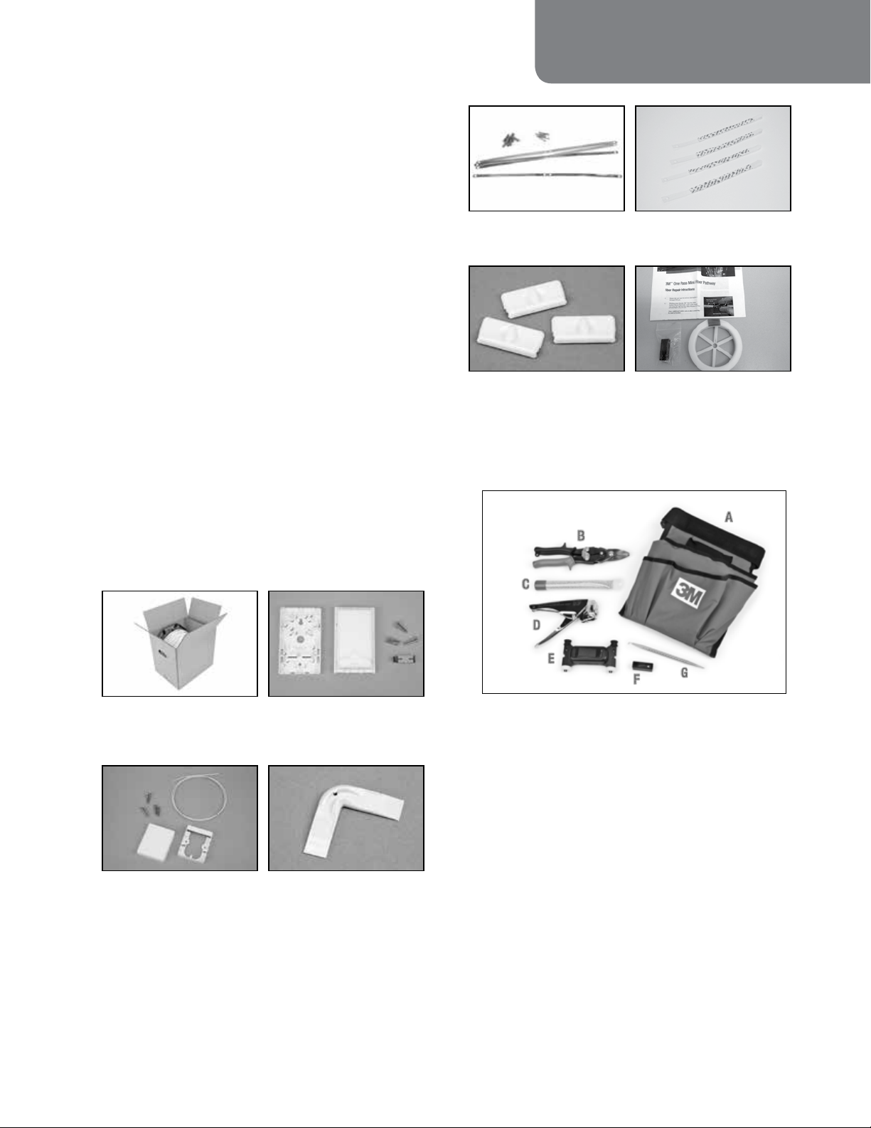
3M™ One Pass Mini Fiber Pathway
Bridge Strips
Mechanical Anchors
80-6113-8216-1
Wall Surface Compatibility
Test Kit 80-6113-9528-8
Fiber Repair Kit
80-6113-8220-3
3.0 Installation Tools
3.1 Installation Tool Kit 80-6113-8222-9
3M’s warranty does not extend to products that have
been subjected to misuse, neglect, accident or improper
installation/alteration.
2.0 Components and Accessories
Duct (optional
configurations available)
Point-of-Entry Wall Cover
80-6113-8214-6
Wall Outlet
(SCA) 80-6113-8213-8
(SCU) 80-6113-8488-6
Planar Corners
80-6113-8125-3
A
B
C
D
E
F
G
a) Pouch 80-6108-4417-9
b) Metal Snips
c) Wall Surface Test Weight
d) Duct Flange Removal Tool 80-6113-8221-1
e) Duct Installation Tool 80-6113-8219-5
f) Window Cut Tool for Fiber Repair
g) Fiber Pick
78-0013-4441-1-D 3
Page 4
3M™ One Pass Mini Fiber Pathway
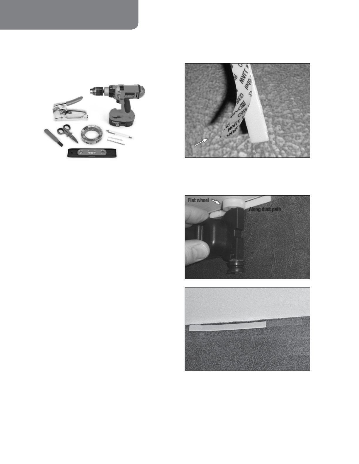
3.2 ILU installation tools are wear items, and should
be replaced on a bi-annual basis, or approximately
every 500 installed units. Sooner as required.
3.3 Additional Recommended Tools (Not Included)
A
B
D
C
E
H
G
F
a) Drill
b) Stapler
c) Splicer’s Knife
d) Fiber Snips
e) ScotchBlue™ Painter’s Tape
f) Level
g) Drill Bits - 5/16" (5 mm)
h) Pen
Wall Surface Compatibility Test Procedure
4.1 Peel liner.
4.2 Press firmly onto wall. Pressing with fingers in
tight spaces is also OK.
Flat wheel
Along duct path
4.0 Wall Surface Compatibility
The wall surface MUST be checked for compatibility with
the adhesive backed One-Pass Mini Fiber Pathway prior to
installation.
This test must be conducted on the most challenging surface
of the installation path (greasy, soiled, textured etc). Or if
installing on multiple wall surfaces, all surfaces must be
tested and all must pass.
Incompatible surfaces include:
• Highly textured walls
• Porous or unfinished/unpainted brick or concrete
• Fabric wall surfaces
• Surfaces with flaking/delaminating paint or wallpaper
NOTE: The One Pass Mini Fiber Pathway should not be
installed on the incompatible surface types listed above.
4 78-0013-4441-1-D
Page 5

3M™ One Pass Mini Fiber Pathway
4.3 Hang weight from strip.
Release tab
Tab hole
Note: Carefully follow safety, health and environmental
information given on the container label or the Material
Safety Data Sheet for the isopropyl alcohol.
Avoid installing on or immediately above direct heat
sources such as radiant heaters, steam pipes, stoves, etc. If
unavoidable, install mechanical anchors on both sides of
heat source as necessary.
Avoid installing in high humidity or water born
environments such as shower stalls, sinks, etc. If
unavoidable, install mechanical anchors on both sides of
area as necessary. Area must be clean and dry at time of
installation and minimum 72 hours following.
For best results, 3M recommends a curing time of 72 hours
after installation of the OnePass Mini Fiber Pathway before
subjecting it to temperature extremes below 60°F (16°C) or
above 100°F (38°C).
5.0 Routing the Duct
4.4 Remove successful test strips by pulling on release tab
Test Weight Hang Time Result
> 60 seconds PASS – Install
< 60 second FAIL – Do not install
The path the duct will follow MUST be clean and dry.
• Clean all surfaces along the duct installation path with
3M™ Easy Trap Duster or equivalent prior to installation.
• Greasy, slick, or soiled surfaces must be cleaned with
isopropyl alcohol or equivalent along the installation path
prior to installation.
• The adhesive is permanent. Removing the duct after
installation may damage the installation surface.
• Do not move or reposition the duct once installed. If for
some reason the duct needs to be moved, a mechanical
anchor is required to secure the duct to the wall on both
sides of the section that has been removed.
• In the event repair is necessary, the materials needed for
repairing the One Pass Mini Fiber Pathway are included
in the repair kit, PN 80-6113-8220-3. (See Fiber Repair
section for instructions).
• The best location is near the ceiling, baseboard and
interior corners. Avoid running duct across open areas or
diagonally across walls.
• Do not remove liner from duct until applying to installation
surface including when handling it while applying to wall
surface.
• Do not contaminate adhesive with dirt or oils. Do not allow
the adhesive to come into contact with anything except the
installation surface as you remove the liner.
Recommended air and duct temperature for installation is
60°F–100°F (16°C–38°C).
78-0013-4441-1-D 5
Page 6

3M™ One Pass Mini Fiber Pathway
• Do not remove duct from box. Route end through handle
as shown and pay off duct.
6.0 Exposing Fiber For Termination
Expose 2-4' (610-1220 mm) of fiber from the end of the
duct before terminating using the following method:
6.1 Snip the flange on either side of the duct, being
careful not to cut the fiber in the duct.
Cut flange on both
sides of duct
6.3 Pull the two sections of duct apart to expose the
fiber.
Pull straight
apart
7.0 Wall Outlet Installation
The beginning and the end of the One Pass Mini Fiber
Pathway must be held down mechanically. This is
accomplished with the cover of the wall outlet box and the
Point-Of-Entry Wall Cover base. If for any reason these
accessories are not used at the beginning and end of the
duct run, use of the adhesive backed mechanical anchor or
equivalent is required.
7.1 Attach the wall outlet base to the wall using two
screws (and anchors if necessary).
7.2 There are 12 ways to route the One Pass Mini
Pathway Duct into the Wall Outlet. Select one and
remove the break-away tab.
Do not cut into
fiber inside duct
6.2 Twist the section to be removed 180°.
Breakaway tab locations
6 78-0013-4441-1-D
Page 7

3M™ One Pass Mini Fiber Pathway
7.3 After exposing appropriate length of fiber for
termination, attach duct by aligning the end of the
duct with the recessed area in the base. Remove the
liner and press firmly into place.
DO NOT ROUTE the 900 µm fiber into the outlet box until
installation of the duct and termination of the connector is
complete.
Align end of duct in recess
8.0 Duct Installation
8.1 Installation Tool
Reference surface guides
Duct profile wheels
Belt clip
9.0 Exterior and Interior Corner Installation
9.1 Exterior Corner: Install duct around corner using
firm pressure.
Note: Do not overstretch duct.
9.2 a) Interior corner: Use wheel of installation tool to
ensure proper bend radius.
Note: Do not overstretch duct or allow adhesive to make
contact with the next wall until the corner is complete!
Do not let adhesive
touch wall
No duct on these wheels
8.2 Installing the duct
Straight away from wall
Firm pressure
10-30°
Remove liner as you go
• The reference surface guides should maintain contact
with reference surface during installation
• Hold duct at same height as duct installation path
• Hold duct out approximately 10-30° from wall
• Do not overstretch duct during installation
• Use firm pressure to securely attach duct to installation
surface
78-0013-4441-1-D 7
Use wheel of
installation tool to ensure
proper bend radius
b) Traverse corner with tool and continue duct
application.
Page 8

3M™ One Pass Mini Fiber Pathway
10.0 Planar Corner Installation
10.1 Peel adhesive liners and attach support in duct path.
Marking grooves
Mark flange at groove
• Proceed SLOWLY and with CAUTION to cut flanges.
Misalignment will
damage fiber!
10.3 Remove liner, press firmly into place around corner.
Remove mark
with fingertip
Leave 12" (300 mm)
of liner intact
10.2 Trim the duct flange using the 3M™ One Pass Mini
Duct Flange Removal Tool.
Example direction of travel
Align mark with
edge of tool
Align duct
carefully in tool
• Align flange against posts at back of tool. Align duct
carefully; misalignment will damage the fiber.
• Align mark to left or right edge of tool, depending on
direction of travel.
Note: No support piece is used in instances where the 90°
planar corner is not on the same wall surface, or when
an angle other that 90° is used.
8 78-0013-4441-1-D
Page 9

3M™ One Pass Mini Fiber Pathway
11.0 Mechanical Anchor Installation
11.1 Remove liner, align groove with duct and press
firmly into place. The anchor may be secured with a
T-25 staple if desired.
T-25 Staple here (optional)
• Use the adhesive-backed anchor wherever additional
adhesion is required, such as: high stress areas, low
adhesion areas, or areas where duct has been pulled off the
wall and has taken the surface with it.
12.0 Bridge Strip Installation
Bridges are used to span disruptions in the installation
surface and to ensure a continuous, uninterrupted
installation path for the duct. They can also be used to
provide additional anchoring in locations where the wall
surface is poor. This is critical to the performance of the
duct. The duct adhesive must never encounter a disruption
in the installation path. If it does, a mechanical anchor must
be used before and after the disruption
12.1 Select a length of bridge strip according to the chart.
Height From Wall Bridge Strip Length
less than 1" (25 mm) 6" (150 mm)
Up to 2" (51 mm) 12" (305 mm)
• Use the bridge strip when surface quality is poor for
adhesion, or to span gaps/holes/obstructions on the
installation surface.
NO GAPS
13.0 Wall Cover Installation
13.1 Remove the tab at the duct entry point as needed.
Furcation
anchors
Duct entry point #1
(intact)
13.2 Fasten the cover to the wall after the duct is
installed. The cover helps secure the end of the duct
to the wall and covers the drilled living unit access
hole.
Screw anchor
locations
Duct
entry
point #3
(hidden)
Duct entry point #2
(removed)
Secure with staples or
#4 screws with anchors
78-0013-4441-1-D 9
Thread fiber through
furcation tubing. Do not
pull fiber tight.
Page 10

3M™ One Pass Mini Fiber Pathway
14.0 Connector Termination and Final Steps
14.1 Terminate the fiber using a 3M™ No Polish
Connector or 3M™ Crimplok+ Connector.
3M™ One Pass Point-of-Entry Box (Hallway Side)
Anchor furcation tubing
14.2 In buildings where the One Pass Fiber Pathway is
not the horizontal cable pathway solution, terminate
the hallway distribution cable (once a penetration
hole is drilled) inside the living unit in a Point-ofEntry Box. Both the One Pass Mini Fiber Pathway
and horizontal distribution cable will terminate here.
Feed through from living unit
14.4 Attach the cover by aligning the bottom tabs to slots
in the base of the box, and then snap the cover in
place.
14.5 The tabs on the cover will hold the duct in place.
3M™ One Pass Mini Fiber Pathway
Horizontal Distribution Cable
Anchor Point
900-micron side Jumper side of box
14.3 After completing installation of the entire run of
duct and terminating the connector, route the 900 µm
fiber and install the connector in the adapter as
shown.
900 µm Fiber
Connector
Tab secures duct
14.6 Align the connector to the adapter and plug. Slide
the door closed.
Adapter
Snap
Locations
10 78-0013-4441-1-D
Page 11

3M™ One Pass Mini Fiber Pathway
15.0 Fiber Repair
15.1 Ensure that the root cause for service interruption is
damaged 900 µm.
15.2 Working away from the Wall Outlet, make small
window cuts using the Window Cut Tool at every
other corner or turn.
Note: Additional window cuts at other corners may be
made if needed.
Distance from Corner
~1" (~25 mm)
Wall Outlet Box
15.3 Cut connectors/fusion splice sleeves from the ends
of the fiber stored inside the Wall Outlet and Pointof-Entry (POE) Cover of the damaged 900 µm fiber.
Pull existing (gray) 900 µm fiber from installed duct
and discard per company practice.
Note: If pulling 900 µm is difficult the window cuts made
in step 2 may be used as intermediate pull back locations.
Window Cut Tool
15.6 Begin pushing 900 µm out the other end of the
window cut until the next window cut is reached.
Insert and push fiber
to next opening
15.7 Repeat steps 5 and 6 until the new fiber is fully
inserted into the duct, through provided furcation
tubing, and into the Point-of-Entry (POE) Box. The
fiber should be flush with each window cut.
White fiber fully inserted
into duct (no excess slack)
Tab secures duct
No cover required
15.4 Wrap 2'-4' (600-1200 mm) of the new white
900 µm fiber into the Wall Outlet to create enough
slack for connector termination and begin pushing it
into the duct.
Note: Keep new 900 µm off of the floor and clean as it
is pushed into the duct to reduce floor debris from being
carried into the duct.
15.5 When the new white 900 µm fiber comes through
each window cut, pull gently at that point to remove
slack.
White Fiber
Cut Length:
~1" (~25 mm)
15.8 Terminate new 900 µm fiber per company practice.
78-0013-4441-1-D 11
Page 12

3M™ One Pass Mini Fiber Pathway
3M and ScotchBlue are trademarks of 3M Company.
Important Notice
All statements, technical information, and recommendations related to 3M’s products are based on information believed to be reliable, but the accuracy or
completeness is not guaranteed. Before using this product, you must evaluate it and determine if it is suitable for your intended application. You assume
all risks and liability associated with such use.
Any statements related to the product which are not contained in 3M’s current publications, or any contrary
statements contained on your purchase order shall have no force or effect unless expressly agreed upon, in writing, by an authorized officer of 3M.
Warranty; Limited Remedy; Limited Liability.
This product will be free from defects in material and manufacture for a period of one (1) year from the time of purchase.
3M MAKES NO OTHER
WARRANTIES INCLUDING, BUT NOT LIMITED TO, ANY IMPLIED WARRANTY OF MERCHANTABILITY OR FITNESS FOR A PARTICULAR PURPOSE.
If this product is defective within the warranty period stated above, your exclusive remedy shall be, at 3M’s option, to replace or repair the 3M product
or refund the purchase price of the 3M product. Except where prohibited by law, 3M will not be liable for any indirect, special, incidental or
consequential loss or damage arising from this 3M product, regardless of the legal theoryasserted.
3
Communication Markets Division
6801 River Place Blvd.
Austin, TX 78726-9000
1-800-426-8688
www.3M.com/Telecom
Please Recycle. Printed in USA.
© 3M 2012. All Rights Reserved.
78-0013-4441-1-D
 Loading...