

Page 1
3
Model 724 Work Station Monitor
Instructions
Page 2

2
Index
Section Page
Safety Information..................................................................................................3
1. Theory of Operation......................................................................................4
2. Installation of 3M™ Model 724 Monitor
with Work Surface Ground Monitoring.........................................................8
3. Installation of Model 724 Monitor
without Work Surface Ground Monitoring ...................................................9
4. Selection of Test Voltage and Resistance Limit ..........................................12
5. Mounting the 724 Monitor and 3M™ Model 732 Remote.........................12
6. Wrist Strap Connection...............................................................................13
7. Fault Conditions..........................................................................................14
8. 3M™ Model 3057 Standby Jack.................................................................15
9. 3M™ Model 733 Dual Conductor Remote Input Jack ...............................15
10. Installation of Model 733 Remote...............................................................15
11. Verification Procedure for the Model 724 Monitor.....................................16
12. Specifications ..............................................................................................19
13. Parts Included..............................................................................................19
14. Required Accessories and Optional Available Parts....................................20
15. Additional Wrist Strap Monitoring Information.........................................20
16. Warranty ......................................................................................................21
Page 3
3
Safety Information
Intended Use
The 3M™Model 724 Work Station Monitor
is designed to monitor the operation of two
wrist strap grounding systems and two
work surfaces. This product has been
designed and tested for use with 3M
™
Dual
Conductor Wrist Straps and 3M Work
Surfaces Grounding Systems. For North
America this unit is designed for use with
an AC adapter included. Outside North
America, obtain an appropriate AC adapter
meeting the specifications as stated in the
user instruction manual (Section 12). Use
of other components may cause improper
performances and/or unsafe conditions. For
use outside of North America, grounding of
the Model 724 Monitor is recommended
through a separate ground wire with ring
terminal supplied (Sections 2 and 3).
CAUTION
• Incorrect grounding of an operator may cause electrostatic discharge (ESD) damage to
components or assemblies being handled. For proper grounding of the operator when
using the 3M 724 Work Station Monitor, use of the three-prong AC adapter specified
in the user instruction manual or supplied ground wire with ring terminal is required.
• Verify that the electrical ground point is suitable. If you are not sure what a suitable
ground is, contact a licensed electrician before installation.
Explanation of Symbols
– Caution: refer to user instruction manual.
– Operator(s) Wrist Strap Assembly Ground.
– W ork Surface Ground.
– Electrical ground.
– Power input connector polarity (center negative).
– See user instruction manual for explanation of the indicator lamps.
Read and understand all safety information before
operating this equipment.
Page 4
4
Section 1.
Theory of Operation
The 3M Model 724 Work Station
Monitor (Fig. 1) is designed to
monitor the operation of the wrist
strap grounding systems of two
operators. To accomplish this, it uses a
DC current source to measure a loop
electrical resistance. The system uses
a special wrist band and ground cord
that contain two independent
elements.* The 724 monitor employs
two selectable test voltages (9 and 16
volts) and resistance limits
(10 Megohms and 35 Megohms).**
It also monitors the grounding of up to
two 3M work surfaces.
The Model 724 monitor performs a
resistance measurement by applying
an electrical current of less than 3 µA
approximately every 2.0 seconds for
0.2 of a second in duration. The path
for the current is through one
conductor of the ground cord that
contains a current-limiting resistor,
through one side of the wrist band,
through the skin of the wearer under
the band, through the second side of
the wrist band, through the second
conductor of the ground cord that
contains a current-limiting resistor,
and finally back to the monitor.
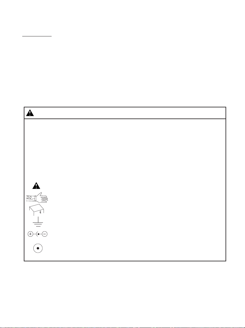
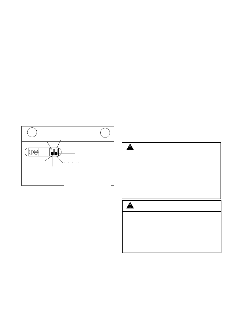
Selection of Test Voltage and
Resistance Limit
Fig. 2 - Resistance/Voltage switch selection.
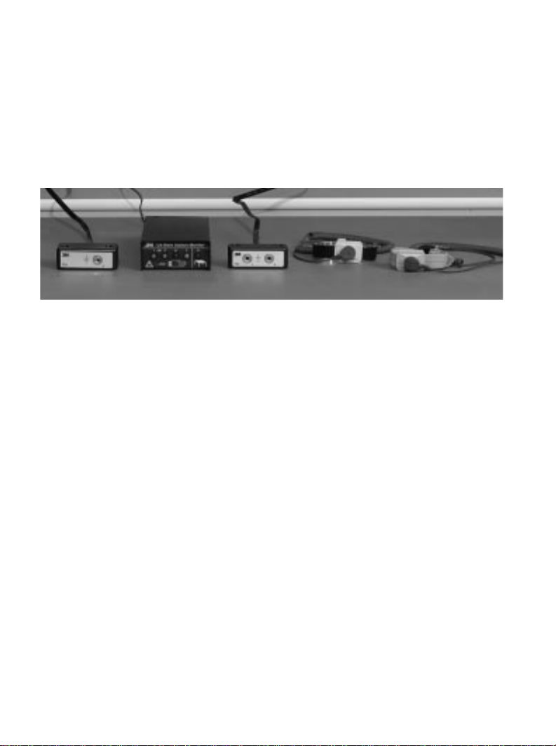
Fig. 1 - Model 724 Work Station with dual conductor wrist strap assemblies and remote input jacks.
Model 724
Work Station
Monitor
Model 732
Remote
Input Jack
Model 733
Remote
Splitter Kit
Dual Conductor
Metal Wrist Strap*
Dual Conductor
Fabric Wrist Strap*
*Resistance values are ±15%
Page 5
5
The Model 724 monitor allows for the
selection of test voltages (9v or 16v)
and resistance limits (10 Megohms or
35 Megohms). The additional ranges
have been added to accommodate
global Electrical Static Discharge
requirements. Selection of the
operating parameters are left up to the
user’s discretion (See Section 4).
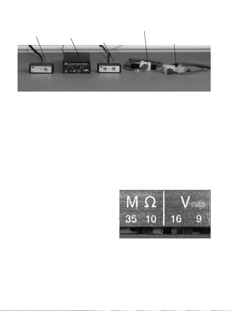
Operator Monitoring Single and Dual
Fig. 3 - Face of Model 724
The wrist strap monitoring function
is activated by plugging a wrist strap
dual conductor ground cord into either
one of the jacks on the 3M™Models
732/733 Dual Conductor Remote
Input Jack. If the resistance of the
wrist strap loop is within the limits of
the selected range (1.5 Megohms to
10 Megohms or 1.5 Megohms to 35
Megohms)* on the Model 724
Monitor, the cord, the wrist band, and
the contact to the arm of the wearer, it
is considered to be functioning
correctly. At this time, one of the
(OK) green lamps (1 or 2) will be
illuminated on the front of
the monitor.
If the resistance of the wrist strap
loop is higher than the selected range
(10 Megohms or 35 Megohms)* on the
724 monitor, an (OK) wrist strap green
lamp (1 or 2) extinguishes, and
a high wrist strap red lamp (H)
illuminates with an audible alarm. This
is an indication of a high resistance in
the cord band, or poor contact between
arm and band. If the resistance in the
loop is under 1.5 Megohms,* it is an
indication of a low resistance meaning
one or both current-limiting resistors
are bypassed. The low yellow lamp (L)
will flash and an (OK) green lamp
(1 or 2) will remain illuminated.
Caution
A low resistance condition can also
be caused by touching a grounded
object or by standing on a
conductive surface.
The wrist strap of a second operator
is measured in the same way. Operators
are identified by the two (OK) green
lamps (1 & 2). However, the same high
wrist strap red lamp (H) and low
yellow (L) lamps illuminate when a
fault is detected. The green lamp that
extinguishes identifies the operator that
is experiencing the fault condition.
* Resistance values are ±15%
3M 733 Remote Splitter Kit purchased separately.
OK #1
Operator
OK #2
Operator
Resistance High Operator
Resistance Low Operator
Resistance High
Work Surface
Page 6

6
Voltage on Operator
When Connected to the
Model 724 Monitor
There is a concern about the voltage
that is applied to an operator while
they are connected to a monitor. Some
of today’s electronic components are
extremely sensitive to electrostatic
discharge from a person (less than
10 volts). The following chart for
the Model 724 monitor illustrates the
level of voltage that will appear on the
operator under various resistance
conditions.
Note:
For more information about wrist strap
monitoring see Additional Wrist Strap
Monitoring Information (Section 15).
Voltage on Operator when connected to the Model 724 monitor
Condition 9V-10 Megohms 9V-35 Megohms 16V-10 Megohms 16V-35 Megohms
No Skin Resistance 0.9V 0.9V 1.6V 1.6V
200K Ohm Skin
Resistance 1.0V 1.0V 1.8V 1.8V
Likely Case Before
Alarm 2.5V 3.6V 4.4V 6.4V
Worst Case Before
Alarm 4.5V 7.1V 8.0V 12.6V
Absolute Worst Case 9.0V 9.0V 16.0V 16.0V
Page 7
7
Audible Alarm T ones
For wrist strap malfunctions the
Model 724 monitor indicates a
different tone for each operator-a
continuous tone for #1 operator and a
fast chirping beep for #2 operator. The
volume of the wrist strap alarm is
adjusted by selection of the internal
DIP switch #1. For work surface
malfunctions, a slow chirping beep is
made. This alarm sound is turned on
or off by selection of DIP switch #2.
Switch #1 and #2 are accessible
through a slot located in the bottom of
the chassis.
Fig. 4 - Selected desired alarm options
Work Surface Monitoring
The Model 724 monitors its
connection to ground and the
grounding of a 3M ESD work surface.
A loop resistance is measured from
the monitor, through a 3M™2380
Monitor/Table Mat Cord to the work
surface (Section 2), across the
conductive layer of the work surface,
through the grounding wire of the
work surface to an electrical ground
and finally back to the monitor through
the 724 grounding wire. If the
resistance of the loop exceeds
3.7 Megohms* the work surface high
red lamp (M) will illuminate and all
green lamps will be extinguished. If
DIP switch #2 is in the ON position
(Fig. 4) the audible alarm will activate.
If no ESD work surface is to be
monitored, the 3M 2380 Monitor/Table
Mat Cord and the ground wire of the
724 must be connected to an electrical
ground (Section 3). This is done to
ensure that the 724 is providing a
ground connection for the operators.
Again, if the loop resistance exceeds
3.7 Megohms the work surface high
red lamp (M) will illuminate and the
alarm will activate if selected.
Caution
The grounding wire from the work
surface and the ground wire from
the Model 724 monitor must be
attached to separate electrical grounds.
The work surface monitoring function
is active any time that the power supply
for the monitor is plugged in.
Caution
Disconnect the 3M 2380 Monitor/
Table Mat Cord to prevent possible
damage to the Model 724 monitor
before testing the resistance of the
work surface with a high voltage
megohmmeter.
* Resistance values are ±15%
DIP Switch
Switch #1
Loud
Switch #2
On
Model 724 Bottom View
Soft
Model 724 bottom view
DIP switch
Off
On
Loud
Switch #2
Switch #1
Page 8

8
Section 2.
Installation of 3M™724
Monitor with Work Surface
Ground Monitoring
Wire Attachments and Grounding See Fig. 12 for complete drawing of
the Model 724 monitor wire
connections.
Tools required - Small blade,
screwdriver and wire cutter.
Note:
Two snap fasteners or appropriate
connectors must be installed at
opposite corners of the work surface to
use this feature. Recommended
surfaces are 3M™8200, 8300, and
8800. Use of a 3M™Female Snap
Fastener 3034 or 3050 (depending on
the type of surface) is recommended
for connection to the 3M™2380
Monitor/Table Mat Cord that is
supplied with the Model 724 monitor.
If you are using the 3M 8300
Dissipative Hard Laminate Material,
attach the 3M™2380 cord to suitable
hardware used to make an electrical
connection to the ground layer of the
work surface. This may require you to
cut off the plastic cap end of the
2380 cord.
a) Connect the work surface to
an electrical ground with the
appropriate one megohm ground
cord you received at time of
purchase.
b) Using a small screwdriver move the
DIP switch #2 on the Model 724
monitor to the ON position to
activate the work surface audible
alarm (Fig. 4).
c) Locate the accessory package that
contains a 3M™2380 Monitor/Table
Mat Cord, Model 724 ground wire
(with ring terminal), and the twowire connector plug.
d) Attach the 3M 2380 (tinned wire
end) to the work surface terminal of
the two-wire connector by inserting
it into opening and securing with the
screwdriver (Fig. 5A or 5B). Attach
the plastic cap end to the snap on
the work surface.
Note:
If for any reason a snap fastener
cannot be used on the work surface,
the plastic cap on the end of the 2380
cord can be cut off and replaced with a
ring terminal not supplied (Fig. 6).
e) Determine how you want to ground
the Model 724 monitor:
• If you are grounding through the AC
adapter perform step (2f).
• If you are grounding through the
724 ground wire perform step (2g).
f) Attach the tinned ground wire of the
AC adapter to the ground terminal
of the two-wire connector by
inserting it into opening and
securing with screwdriver (Fig. 5B).
Continue with step (2h).
Page 9

9
g) Attach the tinned Model 724
ground wire to the ground terminal
of the two-wire connector by
inserting the tinned end into
opening and securing with
screwdriver (Fig. 5A). Attach the
ring terminal end with a screw (not
supplied) to an electrical ground
(Fig. 7B). Continue with step (2h).
h) Plug the two wire connector
into the jack at the rear of the
724 monitor (Fig. 8).
i) Insert the plug connector of the 3M
732 Dual Conductor Remote Input
Jack cable into the 732 jack at the
rear of the Model 724 monitor
(Fig. 9).
j) Insert the round connector from the
AC adapter into the jack at the rear
of the 724 monitor
Note:
Disconnect the 3M™2380 cord to
check for visual and audible high
work surface alarm condition and
reconnect. If the high work surface
lamp (M) is on before removing the
2380 cord, check for loose
connections or high resistance to
ground (>3.7 Megohms). Disconnect
the 3M 2380 cord from the work
surface and check the resistance to
ground by attaching one lead of an
ohmmeter to the connector on the
work surface and the other lead
to ground.
Section 3.
Installation of Model 724
Monitor without Work
Surface Ground Monitoring
Wire Attachments and Grounding - See
Fig. 12 for complete drawing of 724
monitor wire connections.
Tools required - Small blade,
screwdriver, and wire cutter.
a) Using a screwdriver move DIP
switch #2 on the Model 724 monitor
to the OFF position to deactivate the
work surface audible alarm (Fig. 4).
b) Locate the accessory package that
contains a 3M™2380 Monitor/Table
Mat Cord, Model 724 ground wire
(with ring terminal), and the twowire connector plug.
c) Attach the 3M™2380 (tinned wire
end) to the work surface terminal of
the two-wire connector plug by
inserting into opening and securing
with screwdriver (Fig. 5A or 5B).
d) Cut off the plastic cap on the
end of the 3M™2380 cord and strip
off approximately 1/2 inch of
insulation and twist the stranded
wire together (Fig. 6). Attach this
end to an electrical ground using a
ring terminal (not supplied) or by
wrapping the wire around the head
of a screw (Fig. 7A).
Page 10

10
e) Determine how you want to ground
the Model 724 monitor:
• If you are grounding through the AC
adapter, perform Step (3f.)
• If you are grounding through the
Model 724 ground wire, perform
Step (3g.)
f) Attach the tinned ground wire of the
AC adapter to the ground terminal of
the two-wire connector by inserting
into opening and securing with
screwdriver (Fig. 5B). Continue with
Step (3h.)
g) Attach the tinned Model 724 ground
wire to the ground terminal of the twowire connector by inserting the tinned
end into opening and securing with
screwdriver (Fig. 5A). Attach the ring
terminal end with a screw (not supplied)
to an electrical ground (Fig. 7B).
Continue with Step (3h.)
h) Plug the two wire connector into the
jack at the rear of the Model 724
monitor (Fig. 8).
Caution
Do not physically connect the 3M
2380 Monitor/Table Mat Cord and the
Model 724 ground wire together. The
ground wire for the work surface and
the ground wire from the 724 monitor
must be attached to separate electrical
grounds. However, by attaching the
wires to the same ground but at a
different physical location, the Model
724 monitor can check for loose or
lost connections to ground. This would
be indicated by the high red work
surface lamp (M) illuminating.
i) Insert the plug connector of the
Model 732 remote cable into the
732 jack at the rear of the Model
724 monitor (Fig. 9).
j) Insert the round connector from the
AC adapter into the jack at the rear
of the Model 724 monitor.
Fig. 5A & 5B - Attaching ground wire/cord and work surface cord to two-wire connector.
Fig. 5A Fig. 5B
Two-Wire Connector
2380
2380
DC Plug
724 Ground Cord
2380
AC Adapter
Ground Wire
AC Adapter
Attach 724 Ground Cord or
AC Adapter Ground Wire
Page 11

11
Fig. 6 - Cutting off table mat ground snap.
Fig. 7A - Attaching system grounds. Note work
surface and unit are grounded at different
locations.
Fig. 7B - Grounding Model 724.
Fig. 8 - Inserting two-wire connector into rear of
Model 724.
Fig. 9 - Inserting 732 plug into rear of Model 724.
Page 12

12
Section 4.
Selection of Test Voltage
and Resistance Limit
Tools required - Small blade,
screwdriver.
The Model 724 monitor allows for the
selection of test voltages (9v or 16v)
and resistance limits (10 Megohms or
35 Megohms). The additional ranges
have been added to accommodate
global ESD requirements. Selection of
the operating parameters are left up to
the user’s discretion.
a) Select the desired resistance and
voltage limit by moving the
appropriate slide switch (with
screwdriver) on the side of the
Model 724 monitor to the desired
position (Fig. 2).
Section 5.
Mounting the 3M™Model 724
Monitor and 3M™Model 732
Remote
a) Mount or position the Model 724
monitor so that the lamps are easily
viewed by the operator (Figs. 10 and
11). Mount the Model 724 monitor
to the underside of a work bench top
or shelf through the two holes
located at the top rear of the case
using the two screws supplied. If
using the screws is not possible,
apply an appropriate amount of
durable, double-sided adhesive
foam tape to the case.
b) Locate the Model 732 Dual
Conductor Remote Input Jack so
that it is convenient for the
operators to attach their wrist strap
ground cord. Mount the remote
with the screws provided.
Fig. 10 - Model 724 mounted on bench top.
Fig. 11 - Model 724 mounted under shelf or bench.
Page 13

13
c) Plug the AC
adapter into a
3-prong grounded
outlet (North
American System).
Outside North
America use
appropriate AC
adapter (see
specifications
Section 11). The
724 monitor is
ready for use.
Section 6.
Wrist Strap Connection
a) Attach a 3M Dual Conductor
Ground Cord to a 3M Dual
Conductor Wrist Band (Fig.13).
Plug the cord into either of the two
jacks on the Model 732 Dual
Conductor Remote Input Jack
(Fig.14). Plugging into a jack
activates the monitor for that input.
b.) The high wrist strap red lamp
(H) should illuminate and the
corresponding audible alarm for
the input (1 or 2) should sound
indicating proper functioning of
the monitor.
c.) Slip the wrist band on your
wrist. The alarm should quiet
and the wrist strap high red lamp
(H) should slowly extinguish.
The corresponding OK wrist
strap green lamp (1 or 2)
should illuminate.
732 Remote
Ground
When not using work station
monitoring feature,connect
work surface wire to ground.
Conductive
Work Surface
Ground
AC
Adaptor
Rear
Ground
722 Monitor
Fig. 13 - Connecting ground cord to wrist band.
Fig. 14 - Connecting wrist snap ground cord to
Model 732.
Fig. 12 - Model 724 wire connection diagram for single
work station.
Ground
Rear
Ground
Ground
AC Adapter
732 Remote
732 Monitor
Conductive
Work Surface
When not using work
station monitoring
feature, connect
work surface wire
to ground.
Page 14

14
Section 7.
Fault Conditions
(Refer to Fig. 3)
Red Wrist Strap Lamp (H)
Accompanied by an A udible Alarm
This indicates that a high resistance
condition (greater than 10 Megohms
or 35 Megohms) exists for an operator
or wrist strap assembly. If two
operators are connected to the monitor
the high condition is with the operator
whose green lamp has extinguished.
Check the operator for good contact
between the wrist and band. Check the
ground cord and connections for
continuity. Some operators have
difficulty in providing sufficient
continuity to the wrist band due to dry
skin or arm hair. They
may need to use an approved skin
moisturizer or reposition the wrist
band on the arm.
Note:
The operators may complain that the
alarm is sounding too often until they
learn to adjust the wrist band to fit
securely or apply an approved skin
moisturizer on a frequent basis.
Please remember that the monitor
is informing you that the operator
is exceeding the established static
control requirement for resistance
to ground when wearing a static
protective wrist strap assembly. These
alarms alert the operator when
sensitive electronics are possibly
being exposed to static electricity.
Prior to incorporating the work
station monitor into your static
control process, the operator was
unaware of these events.
Yellow Wrist Strap Lamp (L) with
no Audible Alarm
Caution
This indicates that a low resistance
condition (less than 1.5 Megohms)
exists between the operator and
ground. One or both of the one
megohm current-limiting resistors are
being bypassed. A low resistance
condition can be caused by touching a
grounded object or by standing on a
conductive surface.
Red Work Surface Lamp (M)
This indicates that a high resistance
condition (greater than 3.7 Megohms)
exists across the conductive layer of
the work surface and/or the ground
connections. Check the work surface,
ground cords, and the connections for
continuity. Note the audible alarm
may also sound if selected.
Page 15

15
Section 8.
3M™Model 3057
Standby Jack
Since the activating switches are
located in the Models 732/733 Dual
Conductor Remote Input Jack, the
normal operating procedure is for the
operators to disconnect their cords
from the remotes when leaving the
work station. However, an optional
standby jack (3M™Model 3057) that
allows the wrist strap ground cord to
remain plugged into the remotes is
available. Simply attach it to any
convenient location then disconnect the
cord from the wrist band and attach it
to the standby jack (Fig. 15). The OK
green lamp (1 or 2) on the Model 724
monitor will illuminate upon
connection. The low yellow lamp (L)
will slowly flash if the standby jack is
grounded. It can be grounded by
attaching a ground wire to the screws
or back plate. It can also be grounded
if the plate is attached to a grounded
metal surface. The operator should
reconnect the wrist strap ground cord
to their wrist band upon returning to
the work station.
Fig. 15 - Attach cord to Model 3057 standby jack.
Section 9.
3M™Model 733 Dual
Conductor Remote
Input Jack
The Model 733 Dual Conductor
Remote Input Jack is used to separate
the two wrist strap jacks on the Model
732 that connect to a Model 724
Monitor. This provides a separation up
to approximately 10 feet apart. This is
done using a second remote input
module (Model 733) in conjunction
with the Model 732 remote input
module originally supplied with the
Model 724 monitor. Two separate work
stations can also be created using the
Model 733 and the 3M™Model 2389
(10 ft.) Monitor/Table Mat Interconnect
Cord. Instructions for creating two
separate work stations are included
with the purchase of the 3M™2389
cord (Fig. 17).
Section 10.
Installation of 733 Remote
a) Insert the plug connector of the
Model 733 Dual Conductor Remote
Input Jack cable into the Model 733
jack at the rear of the Model 724
monitor (Fig. 16).
b) Fully insert the small plastic plug
that comes with the kit into the #2
wrist strap input on the Model 732
Dual Conductor Remote Input Jack.
This disables the #2 input and
prevents a situation where two users
would simultaneously attempt to use
the input lines to the Model 724.
Page 16

16
c) Position and mount both remote
input jacks in convenient locations.
Fig. 16 - Inserting Model 733 plug into rear of
Model 724
Section 11.
Verification Procedure for
the Model 724 Monitor
The Model 724 Monitor cannot be
recalibrated after the initial factory
calibration. However, the following
steps can be used to determine if the
Model 724 is operating within its
specifications.
Equipment Needed:
• Small blade screwdriver.
• Resistance Substitution Box (RSB),
1 Ohm to 45 Megohms ±1%.
Fig. 17 - Model 724 wire connection diagram for two work stations.
™
Page 17

17
• One two-conductor cable with
standard 3.5 mm (miniature)
phone plug attached on one end
and appropriate connectors on the
other end to connect to RSB.
Note:
Two-conductor cable must have an
isolation resistance of >1 Gigohm
between conductors. Two separated
wires may also be used to obtain
higher isolation resistance.
• Two wires with alligator clips.
• Ohmmeter capable of measuring to
45 Megohms ±0.5%, to verify the
RSB.
Procedure:
Work Surface
a) Access the DIP switches SW1 and
SW2 through a slot located at the
bottom of the chassis. Adjust SW1
to the LOUD position and SW2 to
the ON position with a small
screwdriver (Fig 4).
b) Plug in the AC adapter. Note that
the red high work surface lamp
(M) is illuminated with an audible
alarm (slow chirping beep).
c) Adjust DIP switch SW1 to the
SOFT position. Note that the
loudness of the alarm decreases.
d) Adjust DIP switch SW2 to the
OFF position. Note that the audible
alarm is silenced.
e) Attach the 3M™2380 Monitor/Table
Mat Cord and the 724 ground wire
to the RSB using the two wires with
alligator clips. Set the resistance as
follows and observe Model 724
monitor output:
3.1 Megohms – Red work surface
lamp (M) OFF.
4.3 Megohms – Red work surface
lamp (M) ON.
f) Disconnect the cords from the RSB.
g) Connect the ring terminal end of the
Model 724 ground wire to the metal
snap of the 3M™2380 Monitor/Table
Mat Cord. The red work surface
lamp (M) should now be OFF.
Wrist Strap
Set Resistance Limit 10 Megohms and
Test Voltage 9v (Fig. 2).
h) Connect the two-wire cable with
3.5 mm phone plug into the #1 input
of the Model 732 Dual Conductor
Remote Input Jack and attach the
other end to the RSB. Set the
resistance as follows and observe the
Model 724 monitor output:
1.3 Megohms – Yellow low lamp (L)
flashing, green (OK) lamp (1) ON,
and audible alarm OFF.
1.7 Megohms - Yellow low lamp (L)
OFF, green (OK) lamp (1) ON, and
audible alarm OFF.
Page 18

18
8.5 Megohms – High red wrist
strap lamp (H) OFF, green (OK)
lamp (1) ON, and audible alarm
OFF.
11.5 Megohms – High red wrist
strap lamp (H) ON, audible alarm
ON (continuous tone), and green
(OK) lamp (1) OFF.
i) Repeat step (6h) for input #2 of the
732 Dual Conductor Remote Input
Jack. Audible alarm will be a fast
chirping beep.
Set Resistance Limit 35 Megohms and
Test Voltage 9v (Fig. 2).
j) Test as in step (6h) above.
However, set the resistance as
follows and observe the 724
monitor output:
1.3 Megohms – Yellow low lamp
(L) flashing, green (OK) lamp (1)
ON, and audible alarm OFF.
1.7 Megohms – Yellow low lamp
(L) OFF, green (OK) lamp (1) ON,
and audible alarm OFF.
29.8 Megohms – High red wrist
strap lamp (H) OFF, green (OK)
lamp (1) ON, and audible alarm
OFF.
40.2 Megohms – High red wrist
strap lamp (H) ON, audible alarm
ON (continuous tone), and green
(OK) lamp (1) OFF.
k) Repeat step (6j) for input #2 of the
732 Dual Conductor Remote Input
Jack. Audible alarm will be fast
chirping beep.
Set Resistance Limit 10 Megohms and
Test Voltage 16v (Fig. 2).
l) Connect the two-wire cable with
3.5 mm phone plug into the #1
input of the Model 732 Dual
Conductor Remote Input Jack and
attach the other end to the RSB. Set
the resistance as follows and
observe the 724 monitor output:
1.3 Megohms – Yellow low lamp
(L) flashing, green (OK) lamp (1)
ON, and audible alarm OFF.
1.7 Megohms – Yellow low lamp
(L) OFF, green (OK) lamp (1) ON,
and audible alarm OFF.
8.5 Megohms – High red wrist strap
lamp (H) OFF, green (OK) lamp (1)
ON, and audible alarm OFF.
11.5 Megohms – High red wrist
strap lamp (H) ON, audible alarm
ON (continuous tone), and green
(OK) lamp (1) OFF.
m)
Repeat step (6l) for input #2 of the
Model 732 Dual Conductor Remote
Input Jack. Audible alarm will be
fast chirping beep.
Set Resistance Limit 35 Megohms and
Test Voltage 16v (Fig. 2).
Page 19

19
n) Test as in step (6l) above. However,
set the resistance as follows and
observe the 724 Monitor output:
1.3 Megohms - Yellow low lamp
(L) flashing, green (OK) lamp (1)
ON, and audible alarm OFF.
1.7 Megohms - Yellow low lamp
(L) OFF, green (OK) lamp (1) ON,
and audible alarm OFF.
29.8 Megohms - High red wrist
strap lamp (H) OFF, green (OK)
lamp (1) ON, and audible alarm
OFF.
40.2 Megohms - High red wrist
strap lamp (H) ON, audible alarm
ON (continuous tone), and green
(OK) lamp (1) OFF.
o) Repeat step (6n) for input #2 of the
Model 732 Dual Conductor
Remote Input Jack. Audible alarm
will be fast chirping beep.
Section 12.
Specifications
724 Monitor Size:
6.5 x 3.125 x 1.375 in.
(16,5 x 7,9 x 3,5 cm)
732/733 Remote Input Jack Size:
2.75 x 1.0 x 1.0 in.
(7,0 x 2,5 x 2,5 cm)
Power Supply Requirements:
Input: 120 V ac +/-10%
(North America)
Output: 25 Vdc @ 50 mA
rated load
Output Plug Polarization:
Center Negative
Output Plug Dimensions: 5,5mm O.D.
x 2,1mm I.D. x 9,5mm Length
Accuracy: +/-15%
T est Voltage: 9 VDC / 16 VDC
Open circuit
Test Current: Less than 3 microamps
Environmental Operating Conditions:
Temperature:
Maximum 110°F / 43°C
Minimum 50°F / 10°C
Humidity:
Maximum 75% R.H.
Section 13.
Parts Included
1 ea. Model 724 Work Station
Monitor
1 ea. Model 732 Dual Conductor
Remote Input Jack
1 ea. AC Adapter (North America
Only for outside North America
see Power Supply
Requirements (Section 12)
1 ea. 724 Ground Cord
1 ea. 2380 Monitor/Table Mat Cord
1 ea. Two-Wire Connector
4 ea. Mounting Screws
2 ea. Wire Management Clips
1 ea. User Instruction Manual
Page 20

20
Section 14.
Section 15.
Additional Wrist Strap
Monitoring Information
Suggested reading on wrist strap
requirements and wrist strap
monitoring:
• EIA 625 - Requirements for
Handling Electrostatic-DischargeSensitive (ESDS) Devices.
• EN100015/1 - Protection of
Electrostatic Sensitive Devices.
• 3M Tech. Response #123 - Pulsed
Current vs. Constant Current in
Work Station Monitors.
• 3M Static Digest Issue No.1, 1998 Disc Drive Industry - Static Control
Considerations.
Note:
The 3M references are available by
calling 3M Electronic Handling &
Protection Division Customer Service
Department at 1-800-328-1368.
Industry standards (EIA & EN) are
available through Global Engineering
Documents at 1-800-854-7179.
Required Accessories and Optional Available Parts
Model No. Description Size
2361 Dual Conductor Fabric Wrist Strap* small
2362 Dual Conductor Fabric Wrist Strap* medium
2363 Dual Conductor Fabric Wrist Strap* large
2364 Dual Conductor Fabric Wrist Band small
2365 Dual Conductor Fabric Wrist Band medium
2366 Dual Conductor Fabric Wrist Band large
2368 Dual Conductor Fabric Wrist Band adjustable
2381 Dual Conductor Metal Wrist Strap* small
2382 Dual Conductor Metal Wrist Strap* medium
2383 Dual Conductor Metal Wrist Strap* large
2384 Dual Conductor Metal Wrist Band small
2385 Dual Conductor Metal Wrist Band medium
2386 Dual Conductor Metal Wrist Band large
2360 Dual Conductor Coil Cord 5 ft.(1,5 m.)
2370 Dual Conductor Coil Cord 10 ft.(3,0 m.)
2371 Dual Conductor Coil Cord 20 ft.(6,0 m.)
2380 Monitor-Table Mat Replacement Cord (No resistor) 6 ft.(1,8 m.)
2389 Monitor-Table Mat Replacement Cord (No resistor) 10 ft.(3,0 m.)
3057 Stand-By Jack 1.9 x 1.3 x 1.1 in. (4,8 x 3,3 x 2,8 cm)
732 Replacement Remote Input Jack 6.5 x 3.1 x 1.4 in.(16,5 x 7,9 x 3,5 cm)
733 Dual Remote Splitter Kit 6.5 x 3.1 x 1.4 in.(16,5 x 7,9 x 3,5 cm)
* Includes band & cord
Page 21

21
Section 16.
Warranty
Limited Warranty - 3M expressly
warrants that for a period of one year
from the date of purchase, 3M static
control products will be free of
defects in materials (parts) and
workmanship (labor).
Defects occuring during the warranty
period will be repaired or products will
be replaced at 3M’s option and expense
if 3M receives notice during the
warranty period. Defective products
must be returned to 3M with proof
of purchase date.
Warranty Exclusions -THE
FOREGOING EXPRESS WARRANTY
IS MADE IN LIEU OF ALL OTHER
PRODUCT WARRANTIES, EXPRESS
AND IMPLIED.
INCLUDING FITNESS AND
MERCHANT ABILITY. The express
warranty will not apply to defects of
damage due to accidents, neglect,
misuse, alterations, operator error,
or failure to properly maintain, clean,
or repair products.
Limit of Liability - In no event will
3M or Seller be responsible or liable for
special, incidental, or consequential
losses or damages, whether based in
tort or contract. Fulfillment of 3M’s
warranty obligations will be Customer’s
exclusive remedy and 3M’s and Seller’s
limit of liablity for any breach of
warranty or otherwise.
 Loading...