

Page 1

Instructions and Parts List
™
3M-Matic
700a-s Type 10500
Adjustable
Case Sealer
with
™
Important Safety
Information
BEFORE INSTALLING OR
OPERATING THIS
EQUIPMENT
Read, understand, and follow
all safety and operating
instructions.
Ac c uGlide SST
Taping Heads
Serial No.
For reference, record machine serial number here.
Spare Parts
It is recommended you
immediately order the spare
parts listed in the "Spare
Parts/Service Information"
section. These parts are
expected to wear through
normal use, and should be
kept on hand to minimize
production delays.
3M Industrial Adhesives and Tapes
3M Center, Building 220-5E-06
St. Paul, MN 55144-1000
3M-Matic™and AccuGlide™ are Trademarks
of 3M, St. Paul, MN 55144-1000
Printed in U.S.A.
© 3M 2005 44-0009-2038-7 (A)
Page 2

Page 3

Replacement Parts and Service Information
To Our Customers:
This is the 3M-Matic™/AccuGlide™/Scotch® equipment you ordered. It
has been set up and tested in the factory with Scotch
assistance or replacement parts are needed, call or fax the appropriate
number listed below.
Included with each machine is an Instructions and Parts List manual.
Technical Assistance:
3M-Matic™ Helpline – 1-800/328 1390. Please provide the customer support
coordinator with the machine number, machine type/model and serial number.
If you have a technical question that does not require an immediate response,
®
tapes. If technical
you may Fax it to 651-736-7282.
Replacement Parts and Additional Manuals
Order parts by part number, part description and quantity required. Also,
when ordering parts and/or additional manuals, include machine name,
number and type. A parts order form is provided at the back of this manual.
3M/Tape Dispenser Parts
241 Venture Drive 1-800/344 9883
Amery, WI 54001-1325 FAX# 715/268 8153
Minimum billing on parts orders will be $25.00. Replacement part prices available on request.
$10.00 restocking charge per invoice on returned parts.
Note : Outside the U.S., contact the local 3M subsidiary for parts ordering information.
3M Industrial Adhesives and Tapes
3M Center, Building 220-5E-06
St. Paul, MN 55144-1000
3M-Matic™, AccuGlide™ and Scotch™ are Trademarks of
3M, St. Paul, MN 55144-1000
Printed in U.S.A.
© 3M 2005 44-0009-1851-4 (F)
Page 4

Page 5

Replacement Parts And Service Information
To Our Customers:
This is the 3M-Matic™/AccuGlide™/Scotch® equipment you ordered. It
has been set up and tested in the factory with Scotch
problems occur when operating this equipment and you desire a service
call or phone consultation, call, write or fax the appropriate number listed
below.
Included with each machine is an Instructions and Parts List manual.
SERVICE, REPLACEMENT PARTS AND ADDITIONAL MANUALS
AVAILABLE DIRECT FROM:
®
tapes. If any
Order parts by part number, part description and quantity required. Also, when
ordering parts and/or additional manuals, include machine name, number and
type.
3M-Matic™, AccuGlide™ and Scotch™ are Trademarks of
3M Industrial Adhesives and Tapes
3M Center, Building 220-5E-06
St. Paul, MN 55144-1000
3M, St. Paul, MN 55144-1000
Printed in U.S.A.
© 3M 2005 44-0009-1852-2(E)
Page 6

Page 7

Instruction Manual
700a-s Stainless Steel, Adjustable Case Sealer, Type 10500
This instruction manual is divided into two sections as follows:
Section
Section
I Includes all information related to installation, operation and parts for the case sealer.
II Includes specific information regarding the AccuGlide™ SST 2 Inch Taping Heads.
Table of Contents Page
Section I – 700a-s Stainless Steel Adjustable Case Sealer
Intended Use ................................................................................................................................... 1
Equipment Warranty and Limited Remedy...................................................................................... 2
700a-s Contents .............................................................................................................................. 2
Important Safeguards ...................................................................................................................... 3 - 6
Specifications .................................................................................................................................. 7 - 9
Installation and Set-Up .................................................................................................................... 10 - 13
Receiving and Handling ...................................................................................... 10
Machine Set-Up.................................................................................................. 10 - 13
Packaging and Separate Parts ................................................................. 10 -11
Machine Bed Height.................................................................................. 12
Outboard Tape Roll Mounting ................................................................... 12
Tape Leg Length....................................................................................... 12
Box Size Capacity of Case Sealer............................................................. 13
Electrical Connection and Controls ........................................................... 13
Initial Start-Up of Case Sealer................................................................... 13
Operation......................................................................................................................................... 14 - 18
Electrical On/Off Switch...................................................................................... 15
Emergency Stop Switch...................................................................................... 15
Tape Loading/Threading..................................................................................... 15
Box Size Set-Up ................................................................................................. 16 - 18
Adjust Upper Taping Head........................................................................ 16
Adjust Side Guides ................................................................................... 16
Run Boxes To Check Adjustment ............................................................. 17
Top Flap Compression Rollers.................................................................. 17
Adjust Compression Rollers...................................................................... 18
Box Sealing ........................................................................................................ 18
(Table of Contents continued on next page)
i
Page 8

Table of Contents (Continued) Page
Maintenance.................................................................................................................................... 19 - 21
Cleaning ............................................................................................................. 19
Lubrication.......................................................................................................... 19
Box Drive Belt Replacement............................................................................... 20
Circuit Breaker.................................................................................................... 21
Blade Replacement, Taping Head ...................................................................... 21
Adjustments ................................................................................................................................... 22 - 24
Box Drive Belt Tension ....................................................................................... 22 - 23
Taping Head Adjustments .................................................................................. 24
Troubleshooting............................................................................................................................... 28
Electrical Diagram ........................................................................................................................... 29
Parts and Service Information ......................................................................................................... 30
Options/Accessories........................................................................................................................ 31
Replacement Parts Illustrations and Parts Lists......................................................(Yellow Section) 32 - 55
Section II – AccuGlide™ SST 2 Inch Taping Heads
(See Section II for Table of Contents)
ii
Page 9
Intended Use
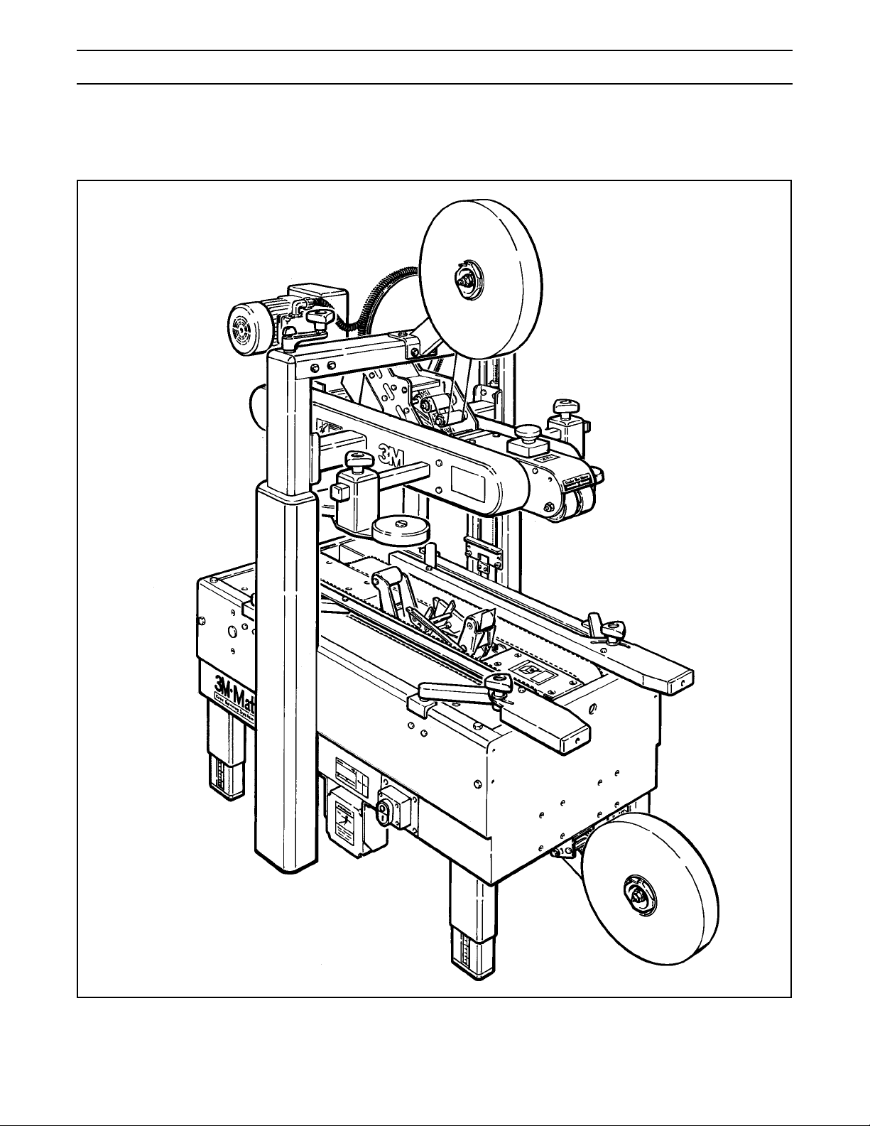
The 3M-MaticTM 700a-s Stainless Steel Adjustable Case Sealer with AccuGlideTM SST Taping Heads is designed
to apply a “C” clip of Scotch® pressure-sensitive film box sealing tape to the top and bottom center seam of regular
slotted containers. The 700a-s is manually adjustable to a wide range of box sizes (see "Specifications Section –
Box Weight and Size Capacities").
3M-MaticTM 700a-s Stainless Steel Adjustable Case Sealer, Type 10500
Note – Lower tape supply roll and bracket assembly are shown in the alternate location.
1
Page 10

Equipment Warranty and Limited Remedy: THE FOLLOWING WARRANTY IS MADE IN LIEU OF ALL
OTHER WARRANTIES, EXPRESS OR IMPLIED, INCLUDING, BUT NOT LIMITED TO, THE IMPLIED
WARRANTY OF MERCHANTABILITY, THE IMPLIED WARRANTY OF FITNESS FOR A PARTICULAR
PURPOSE AND ANY IMPLIED WARRANTY ARISING OUT OF A COURSE OF DEALING, A CUSTOM OR
USAGE OF TRADE:
3M sells its 3M-Matic
™
700a-s Adjustable Case Sealer, Type 10500
with the following warranties:
1. The drive belts and the taping head knives, springs and rollers will be free from all defects for ninety (90)
days after delivery.
2. All other taping head parts will be free from all defects for three (3) years after delivery.
3. All other parts will be free from all defects for two (2) years after delivery.
If any part is proved to be defective within its warranty period, then the exclusive remedy and 3M’s and seller’s
sole obligation shall be, at 3M’s option, to repair or replace the part, provided the defective part is returned
immediately to 3M’s factory or an authorized service station designated by 3M. A part will be presumed to have
become defective after its warranty period unless the part is received or 3M is notified of the problem no later than
five (5) calendar days after the warranty period. If 3M is unable to repair or replace the part within a reasonable
time, then 3M at its option, will replace the equipment or refund the purchase price. 3M shall have no obligation
to provide or pay for the labor required to install the repaired or replacement part. 3M shall have no obligation to
repair or replace (1) those parts failing due to operator misuse, carelessness, or due to any accidental cause
other than equipment failure, or (2) parts failing due to non-lubrication, inadequate cleaning, improper operating
environment, improper utilities or operator error.
Limitation of Liability: 3M and seller shall not be liable for direct, indirect, special, incidental or consequential
damages based upon breach of warranty, breach of contract, negligence, strict liability or any other legal theory.
The foregoing Equipment Warranty and Limited Remedy and Limitation of Liability may be changed only by a
written agreement signed by authorized officers of 3M and seller.
Contents – 700a-s Stainless Steel Adjustable Case Sealer
(1 ) 700a-s Stainless Steel Adjustable Case Sealer, Type 10500
(1 ) Upper Assembly Height Adjustment Crank/Hardware
(1 ) Upper Tape Drum/Bracket/Hardware
(2 ) Column Stop Bracket/Hardware
(1 ) Tool/Spare Parts Kit
(1 ) Instruction and Parts Manual
Scotch
®
, AccuGlideTM, and 3M-MaticTM are Trademarks of 3M, St. Paul, Minnesota 55144-1000
2
Page 11
Important Safeguards
This safety alert symbol identifies
important messages in this manual.
READ AND UNDERSTAND THEM BEFORE
INSTALLING OR OPERATING THIS
EQUIPMENT.
Explanation of Signal Word Consequences
WARNING:
CAUTION:
Indicates a potentially hazardous
situation, which, if not avoided,
could result in death or serious
injury and/or property damage.
Indicates a potentially hazardous
situation, which, if not avoided,
may result in minor or moderate
injury and/or property damage.
WARNING
• To reduce the risk associated with
mechanical and electrical hazards:
− Read, understand and follow all safety and
operating instructions before operating or
servicing the case sealer
− Allow only properly trained and qualified
personnel to operate and/or service this
equipment
− Turn electrical supply off and disconnect
before performing any adjustments,
maintenance or servicing the machine or
taping heads
• To reduce the risk associated with pinch
and entanglement hazards:
− Do not leave the machine running while
unattended
WARNING (continued)
• To reduce the risk associated with sharp
blade hazards:
− Keep hands and fingers away from tape cutoff
blades under orange blade guards. The
blades are extremely sharp
• To reduce the risk associated with fire and
explosion hazards:
− Do not operate this equipment in potentially
flammable/explosive environments
• To reduce the risk associated with muscle
strain:
− Use the appropriate rigging and material
handling equipment when lifting or
repositioning this equipment
− Use proper body mechanics when removing
or installing taping heads that are moderately
heavy or may be considered awkward to lift
CAUTION
• To reduce the risk associated with pinch
and entanglement hazards:
− Keep hands clear of the upper head support
assembly as boxes are transported through
the machine
− Keep hands, hair, loose clothing and jewelry
away from box compression rollers
− Always feed boxes into the machine by
pushing only from the end of the box
− Keep hands, hair, loose clothing, and jewelry
away from moving belts and taping heads
− Turn the machine off while not in use
− Never attempt to work on any part of the
machine, load tape, or remove jammed boxes
from the machine while the machine is
running
• To reduce the risk associated with
hazardous voltage:
− Position electrical cord away from foot and/or
vehicle traffic
3
Page 12
Important Safeguards (Continued)
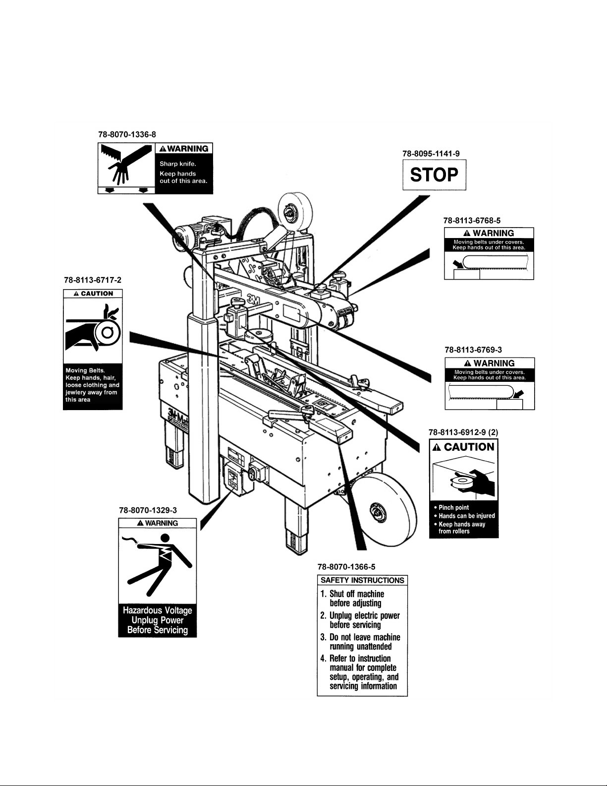
Important – In the event the following safety labels are damaged or destroyed, they must be replaced to ensure
operator safety. Replacement part numbers for individual labels are shown in Figures 1-1 and 1-2, or a label kit,
part number 78-8098-9175-3, is available that includes all labels used on the machine.
Figure 1-1 – Replacement Labels/3M Part Numbers
4
Page 13
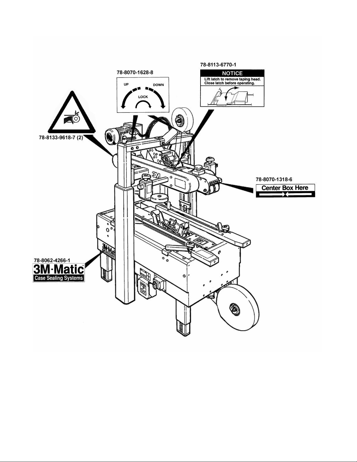
Important Safeguards (Continued)
Figure 1-2 – Replacement Labels/3M Part Numbers
78-8060-8481-6 (4)
Leg Height Adjustment Label
(Not shown)
78-8070-1339-2 (2)
3M Logo (Each side of upper
assembly - Not shown)
5
Page 14

Important Safeguards (Continued)
WARNING
• To reduce the risk associated with
mechanical and electrical hazards:
− Allow only properly trained and qualified
personnel to operate and/or service this
equipment
Operator Skill Level Descriptions
Skill 1 - Machine Operator
This operator is trained to use the machine with the
machine controls, to feed cases into the machine,
make adjustments for different case sizes, to change
the tape and to start, stop and restart production.
N.B.: the factory manager must ensure that the
operator has been properly trained on all the machine
functions before starting work.
Skill 2 - Mechanical Maintenance Technician
This operator is trained to use the machine as the
MACHINE OPERATOR and in addition is able to work
with the safety protection disconnected, to check and
adjust mechanical parts, to carry out maintenance
operations and repair the machine. He is not allowed
to work on live electrical components.
Skill 2a - Electrical Maintenance Technician
This operator is trained to use the machine as the
MACHINE OPERATOR and in addition is able to work
with the safety protection disconnected, to make
adjustments, to carry out maintenance operations and
repair the electrical components of the machine. He is
allowed to work on live electrical panels, connector
blocks, control equipment, etc.
Skill 3 - Specialist From the Manufacturer
Skilled operator sent by the manufacturer or its agent
to perform complex repairs or modifications, when
agreed with the customer.
Operator's Skill Levels Required to Perform the Main Operations on Machine
noitarepOenihcaMehtfoetatS
.enihcamehtfoputesdnanoitallatsnI
.ezisxobehtfotnemtsujdA
ecalperepaT
.tnem
.sedalbfotnemecalpeR.detcennocsidrewopcirtcelE21
.stl
ebevirdfotnemecalpeR.detcennocsidrewopcirtcelE21
.ecnanetniamyranidrO.detcennocsidrewopcirtcelE21
yranidroartxE
.)lacinahcem(
ecnanetniam
.delbasid
.delbasid
ytefashtiwgninnuR
snoitcetorp
ehtgnisserpybdeppotS
.nottubPOTSYCNEGREME
ehtgnisserpybdeppotS
.nottubPOTSYCNEGREME
snoitcetorpytefashtiwgninnuR
s'rotarepO
llikS
a2dna22
11
11
31
forebmuN
srotarepO
.)lacirtcele(ecnanetniamyranidroartxE
.delbasid
6
snoitcetorpytefashtiwgninnuR
a21
Page 15
Specifications
1. Power Requirements:
Electrical - 115 VAC, 60 Hz, 5.6 A
The machine is equipped with a 2.4 m [8 foot] standard neoprene covered power cord and a grounded plug.
Contact your 3M Representative for power requirements not listed above.
2. Operating Rate:
Box drive belt speed is approximately 0.4 m/s [78 feet per minute].
3. Operating Conditions:
IMPORTANT SAFEGUARD
Use in a relatively clean environment at 5o to 40o C [40o to 105o F] with clean, dry boxes.
Important: Machine should not be washed down.
WARNING
IMPORTANT SAFEGUARD
• To reduce the risk associated with fire and
explosion hazards:
− Do not operate this equipment in potentially
flammable/explosive environments
4. Tape:
Scotch® pressure-sensitive film box sealing tapes.
5. Tape Width:
36 mm [1 1/2 inch] minimum to 48 mm [2 inch] maximum
(Specifications continued on next page.)
7
Page 16

Specifications (Continued)
6. Tape Roll Diameter:
Up to 405 mm [16 inch] maximum on a 76.2 mm [3 inch] diameter core.
(Accommodates all system roll lengths of Scotch
7. Tape Application Leg Length – Standard:
70 mm ± 6 mm [2.75 inch ±.25 inch ]
8. Box Board:
Style – regular slotted containers – RSC
125 to 275 P.S.I. bursting test, single wall or double wall B or C flute.
9. Box Weight and Size Capacities:
A. Box Weight, filled – up to 38.6 kg [85 lbs.] maximum. Contents must support flaps.
B. Box Size: Minimum Maximum
Length – 150 mm [6.0 inch] Unlimited
Width – 150 mm [6.0 inch]* 550 mm [21.5 inch]
Height – 120 mm [4.75 inch]** 620 mm [24.5 inch] **
®
film tapes.)
* Cartons narrower than 250 mm [10 inch] in width may require more frequent belt replacement
because of limited contact area.
** 165 mm [6.5 inch] minimum to 725 mm [28.5 inch] maximum height with columns adjusted to upper
position. (See "Special Set-Up Procedure – Box and Machine Bed Height Range".)
Special modifications may be available for carton sizes not listed above.
Contact your 3M Representative for information.
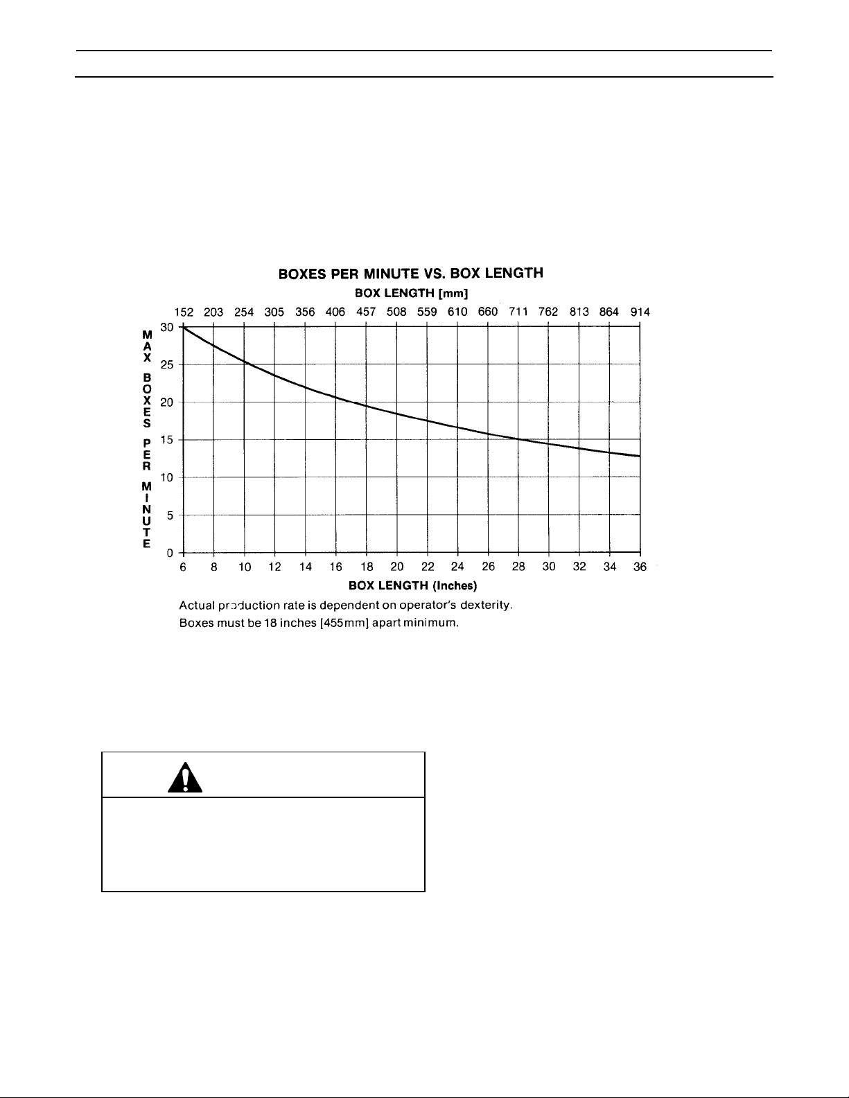
Note: The case sealer can accommodate most boxes within the size range listed above. However, if the
box length (in direction of seal) to box height ratio is .5 or less, then several boxes should be test run to
assure proper machine performance.
DETERMINE THE BOX LIMITATIONS BY COMPLETING THIS FORMULA:
BOX LENGTH IN DIRECTION OF SEAL MUST BE GREATER THAN .5
=
BOX HEIGHT
Any box ratio approaching this limitation should be test run to assure performance.
(Specifications continued on next page.)
8
Page 17
Specifications (Continued)
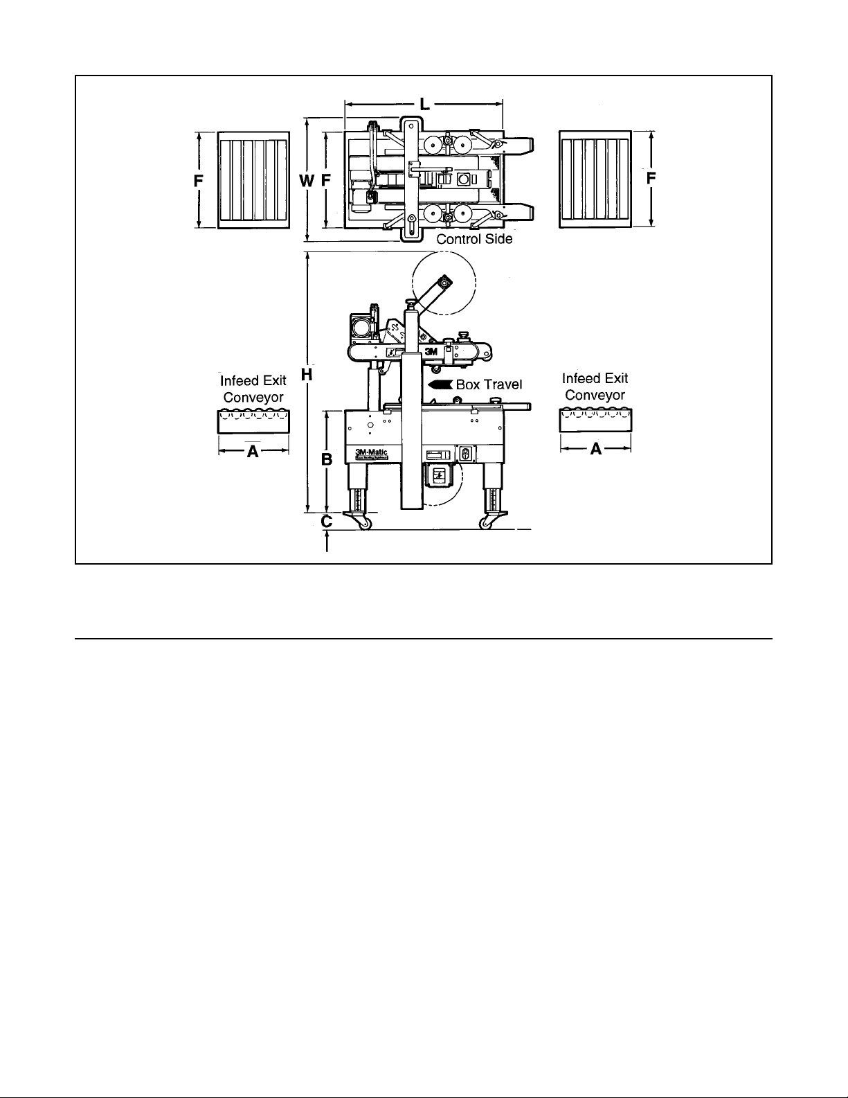
10. Machine Dimensions:
W L H A* B C** F
Minimum
mm 790 1030 1350 460 610 100 625
[Inches] [31] [40 .5] [53] [18] [24]*** [4] [24.5]
Maximum
mm 2185 890
[Inches] - - - - [86]*** - - [35]*** - - - -
* Infeed/Exit conveyors are optional
** Casters are optional
*** When columns are adjusted to upper position, "B" minimum dimension is 520 mm [20.5 inch], maximum
dimension is 780 mm [31 inch] and "H" maximum dimension is 2290 mm [90 inch]. (See "Special Set-Up
Procedure – Box and Machine Bed Height Range".)
Weight – 180 kg [400 lbs] crated (approximate)
160 kg [350 lbs] uncrated (approximate)
11. Set-Up Recommendations:
• Machine must be level.
• Customer supplied infeed and exit conveyors (if used) should provide straight and level box entry and exit.
• Exit conveyors (powered or gravity) must convey sealed boxes away from machine.
9
Page 18
Installation and Set-Up
Receiving And Handling
After the machine has been uncrated, examine the
case sealer for damage that might have occurred
during transit. If damage is evident, file a damage
claim immediately with the transportation company
and also notify your 3M Representative.
Machine Set-Up
WARNING
• To reduce the risk associated with
mechanical and electrical hazards:
− Read, understand and follow all safety and
operating instructions before operating or
servicing the case sealer
The following instructions are presented in the order
recommended for setting up and installing the case
sealer, as well as for learning the operating
functions and adjustments. Following them step by
step will result in your thorough understanding of the
machine and an installation in your production line
that best utilizes the many features built into the case
sealer. Refer to Figure 3-1 to identify the various
components of the case sealer.
6. Loosen and move both compression rollers out
so they don't catch on side guides.
7. Install height adjustment crank and locking knob
on top of left column as shown in
Figure 2-1B. Crank upper assembly up high
enough to allow clear access to lower taping
head. Remove and discard the two cushion
shipping blocks.
8. Using 17 mm wrench, remove nuts from top of
side guides. Replace with black knobs from
parts box. Figure 2-1C.
9. Cut and remove cable ties on both upper and
lower taping heads. (Applying/buffing rollers are
held retracted for shipment.)
WARNING
• To reduce the risk associated with sharp
blade hazards:
− Keep hands and fingers away from tape cutoff
blades under orange blade guards. The
blades are extremely sharp
Note – A tool kit consisting of metric open end
and hex socket wrenches is provided with the
machine. These tools should be adequate to setup the machine, however, other tools supplied by
the customer will be required for machine
maintenance.
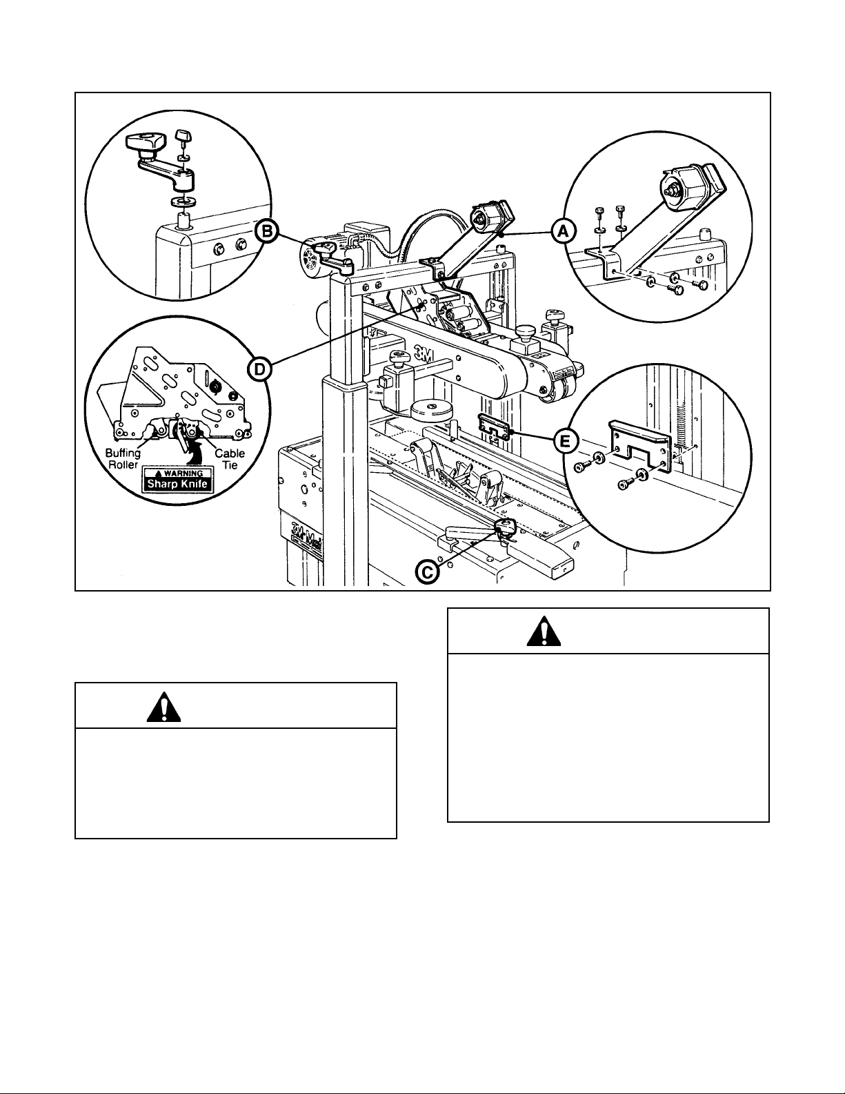
PACKAGING AND SEPARATE PARTS
1. Remove straps and staples and lift fiberboard
cover off pallet.
2. Remove protective wrapping around machine.
3. Cut and remove cable tie from electrical conduit.
4. Cut cable ties that secure upper assembly to
machine bed on each side.
5. Remove tape drum bracket bolts (4) from top
crossbar and install tape drum bracket from
parts box as shown in Figure 2-1A.
Hold taping head BUFFING ROLLER and cut
and remove cable tie that holds applying/
buffing arms retracted. See Figure 2-1D.
Allow buffing/applying arms to extend slowly.
10. Install machine stops onto columns as shown in
Figure 2-1E. Use the lowest hole position and
bolt into the lowest threaded insert on the
column.
10
Page 19
Installation and Set-Up (Continued)
Figure 2-1 – 700a-s Frame Set-Up
11. Check for free action of both upper and lower
taping heads.
WARNING
• To reduce the risk associated with sharp
blade hazards:
− Keep hands and fingers away from tape cutoff
blades under orange blade guards. The
blades are extremely sharp
Push buffing roller into head to check for free,
smooth action of taping heads.
12. Ensure that the tape drum bracket assembly,
located on the lower taping head, is mounted
straight down, as shown in Figure 2-2A. The
tape drum bracket assembly can be pivoted to
provide tape roll clearance in certain cases.
13. Remove fasteners that secure case sealer legs
to pallet.
W ARNING
• To reduce the risk associated with muscle
strain:
− Use the appropriate rigging and material
handling equipment when lifting or
repositioning this equipment
− Use proper body mechanics when removing
or installing taping heads that are moderately
heavy or may be considered awkward to lift
14. Remove the machine from the pallet and move it
into position.
Important – Whenever the machine is lifted with
a fork truck, insure that the forks span completely across the machine frame and do not
contact any wiring or mechanism under the
machine frame. In some cases the lower taping
head may need to be removed to avoid damage.
15. Continue with the remainder of the Installation
and Set-Up procedure through the end of the
11
topic.
Page 20
Installation and Set-Up (Continued)
MACHINE BED HEIGHT
Adjust machine bed height. The case sealer is
equipped with four adjustable legs that are
located at the corners of the machine frame.
The legs can be adjusted to obtain different
machine bed heights from 610 mm [24 inch]
minimum to 890 mm [35 inch] maximum.
Note – Minimum machine bed height can be
reduced to 520 mm [20.5 inch] by moving
outer columns up one set of mounting holes.
However, this change also increases the
minimum box height of 120 mm [4.8 inch] to
165 mm [6.5 inch]. (See "Special Set-Up
Procedure – Box/Machine Bed Height Range".)
1. Use appropriate material handling equipment
and blocking techniques to raise the machine
frame to allow adequate leg adjustment.
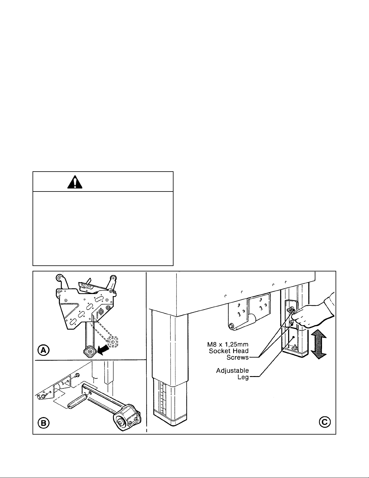
2. Loosen, but do not remove, two M8 x 1.25
socket head screws in one leg (use M6 hex
wrench). Adjust the leg length for the desired
machine bed height. Retighten the two
screws to secure the leg. Adjust all four legs
equally.
OUTBOARD TAPE ROLL MOUNTING
(Lower Taping Head)
Refer to Figure 2-2C and set the machine bed
height as follows:
W ARNING
• To reduce the risk associated with muscle
strain:
− Use the appropriate rigging and material
handling equipment when lifting or
repositioning this equipment
− Use proper body mechanics when removing
or installing taping heads that are moderately
heavy or may be considered awkward to lift
Remove the tape drum bracket assembly, spacer
and fasteners from the lower taping head. Install
and secure on the infeed end of the lower frame,
as shown in Figure 2-2B.
Figure 2-2 – Machine Bed Height Adjustment and Lower Tape Drum Bracket Position
12
Page 21

Installation and Set-Up (Continued)
BOX SIZE CAPACITY OF CASE SEALER
At its factory setting, the case sealer handles box
sizes up to 620 mm [24.5 inch] maximum height.
If larger capacity is needed, the machine can be
adjusted to accommodate boxes up to 725 mm
[28.5 inch] high. Refer to "Special Set-Up
Procedure – Box and Machine Bed Height
Range".
Note – Adjusting machine to accommodate 725
mm [28.5 inch] high boxes also increases
minimum box size to 165 mm [6.5 inch].
ELECTRICAL CONNECTION AND CONTROLS
The electrical control box (with circuit breaker)
and "On/Off" switch are located on the lower left
side of the machine frame. See Figure 3-1. If
desired, for operator convenience, the "On/Off"
switch can be relocated to the right side of the
machine frame. A standard three conductor power
cord with plug is provided at the back of the
electrical control box for 115 Volt, 60 Hz.
electrical service. The receptacle providing this
service shall be properly grounded. Before the
power cord is plugged into 115 Volt, 60 Hz outlet
make sure that all packaging materials and tools
are removed from the machine. Do not plug
electrical cord into outlet until ready to run
machine.
Use of an extension cord is not recommended.
However, if one is needed for temporary use, it
must have a wire size of 1.5 mm diameter
[AWG 16 ], have a maximum length of 30.5 m
[100 ft], and must be properly grounded.
WARNING
• To reduce the risk associated with
hazardous voltage:
− Position electrical cord away from foot and/or
vehicle traffic
Note – Machines outside the U.S. may be
equipped with 220/240 Volt, 50 Hz systems or
other electrical requirements compatible with
local practice.
INITIAL START-UP OF CASE SEALER
After completing the "Installation and Set-Up"
procedure, continue through "Operation" for tape
loading and start-up to be sure case sealer is
properly adjusted to run boxes
13
Page 22

Operation
WARNING
• To reduce the risk associated with mechanical and electrical hazards:
− Read, understand and follow all safety and operating instructions before operating or
servicing the case sealer
Refer to Figure 3-1 below to acquaint yourself with the various components and controls of the case sealer. Also see
Figures 3-1 and 3-2 in Section II for taping head components.
Figure 3-1 – 700a-s Stainless Steel Case Sealer Components (Left Front View)
14
Page 23

Operation (Continued)
Important – Before turning drive belts on, be sure
no tools or other objects are on the conveyor bed.
Electrical "On/Off" Switch
The box drive belts are turned on and off ("Off"
button is red) with the electrical switch on the side of
the machine frame.
Note – The case sealer has a circuit breaker
located in the electrical enclosure on the lower left
side of the machine frame. If circuit becomes
overloaded and circuit breaker trips, unplug the
machine electrical cord and determine cause of
overload. After two minutes, open the electrical
enclosure and reset the circuit breaker by lifting
the reset lever. Close the electrical enclosure, plug
machine electrical cord into outlet and restart
machine by pressing "I" (On) button.
Emergency Stop Switch
The machine electrical supply can be turned off by
pressing the latching emergency stop switch. To
restart machine, rotate emergency stop switch
(releases switch latch) and then restart machine by
pressing "I" (On) button on side of machine frame.
Tape Loading/Threading
See Section II, Operation Section.
Note – If lower tape drum is mounted in alternate
lower outboard position, remove taping head from
machine bed by pulling straight up, insert
threading needle in taping head and replace
taping head. Install tape roll on drum (adhesive on
tape leg up), thread tape under knurled roller on
outboard mount, then attach tape to threading
needle and pull tape through taping head with
threading needle.
W ARNING
• To reduce the risk associated with muscle
strain:
− Use proper body mechanics when removing
or installing taping heads that are moderately
heavy or may be considered awkward to lift
15
Page 24

Operation (Continued)
Box Size Set-Up
1. ADJUST UPPER TAPING HEAD
The upper taping head is positioned for the box
height by means of the height adjustment crank
shown in Figure 3-2. Turn crank clockwise to
lower head, counterclockwise to raise head.
Move the top flap compression rollers to a
position wider than the box.
Place box on infeed end of machine bed with both
top and bottom flaps folded and insert under
upper head ski approximately 150 mm
[6 inch] as shown in Figure 3-3. Lower the head
until all flaps are fully closed. Align box top flap
center seam with arrows on front of upper frame.
Figure 3-2 – Upper Taping Head
2. ADJUST SIDE GUIDES (Figure 3-4)
Align box top flap center seam with arrows on
front of ski.
Move side guides against each side of box to
hold box in position, centered on arrows on front
of ski.
Tighten hand knobs to secure side guides.
Figure 3-3 – Upper Taping Head
Figure 3-4 – Side Guides
16
Page 25

Operation (Continued)
3. RUN BOXES TO CHECK ADJUSTMENT
(Figure 3-5)
Important – Before turning drive belts on, be
sure no tools or other objects are on the conveyor
bed.
CAUTION
• To reduce the risk associated with pinch
and entanglement hazards:
− Keep hands clear of the upper head support
assembly as boxes are transported through
the machine
Turn electrical switch to "On" to start drive belts.
Move box forward under upper taping head until it
is taken away by drive belts. If box is hard to
move under head or is crushed, raise head
slightly. If box movement is jerky or stops under
upper head, lower upper head slightly to add
more pressure between box and drive belts.
Figure 3-5 – Check Adjustments
Note – Upper head has unique feature for
overstuffed boxes. The head will raise up to
13 mm [1/2 inch] to compensate for this type
of condition.
Important – If drive belts are allowed to slip on
box, excessive belt wear will occur.
4. TOP FLAP COMPRESSION ROLLERS
(Figure 3-6)
CAUTION
• To reduce the risk associated with pinch
and entanglement hazards:
− Keep hands, hair, loose clothing and jewelry
away from box compression rollers.
The top flap compression rollers have two
mounting positions to provide side compression
through the full range of box widths.
The rollers have been pre-assembled in position
"B" to accommodate box widths from 200 mm
[8 inch] to 545 mm [21.5 inch] maximum.
Figure 3-6 – Compression Rollers
To accommodate box widths less than 200 mm
[8 inch] to 140 mm [5.5 inch] minimum, move all
four rollers to position "A".
Adjust the top flap compression rollers against
top edge of box and tighten knobs to secure
rollers in operating position.
17
Page 26

Operation (Continued)
5. ADJUST COMPRESSION ROLLERS
Adjust the top flap compression rollers against
top edge of box and tighten knobs to secure
rollers in operating position as shown in
Figure 3-7.
Box Sealing
CAUTION
• To reduce the risk associated with pinch
and entanglement hazards:
− Keep hands clear of the upper head support
assembly as boxes are transported through
the machine
− Always feed boxes into the machine by
pushing only from the end of the box
− Keep hands, hair, loose clothing and jewelry
away from box compression rollers
− Keep hands, hair, loose clothing, and jewelry
away from moving belts and taping heads
WARNING
• To reduce the risk associated with pinch,
entanglement, and hazardous voltage:
− Never attempt to work on any part of the
machine, load tape, or remove jammed boxes
from the machine while the machine is
running
1. Feed boxes to machine at minimum 455 mm
[18 inch] intervals.
2. Reload and thread tape as necessary.
Figure 3-7 – Compression Rollers
Notes –
1. Machine or taping head adjustments are
described in "Adjustments" Section I for
machine or Section II for taping heads.
2. Box drive motors are designed to run at a
moderate temperature of 40°C [104°F]. In
some cases, they may feel hot to the
touch.
3. Be sure machine is cleaned and lubricated
according to recommendations in "Maintenance"
section of this manual.
WARNING
• To reduce the risk associated with pinch
and entanglement hazards:
− Do not leave the machine running while
unattended
18
Page 27

Maintenance
The case sealer has been designed for long, trouble
free service. The machine will perform best when it
receives routine maintenance and cleaning. Machine
components that fail or wear excessively should be
promptly repaired or replaced to prevent damage to
other portions of the machine or to the product.
WARNING
• To reduce the risk associated with
mechanical and electrical hazards:
− Read, understand and follow all safety and
operating instructions before operating or
servicing the case sealer
− Allow only properly trained and qualified
personnel to operate and/or service this
equipment
− Turn electrical supply off and disconnect
before performing any adjustments,
maintenance or servicing the machine or
taping heads
Lubrication
Most of the machine bearings, including the drive
motor, are permanently lubricated and sealed and do
not require additional lubricant.
Figure 4-1 illustrates the machine points that do
require lubrication every 250 hours of operation.
Lubricate the points indicated by arrows ( ) with a
small amount of multi-purpose grease.
Note – Wipe off excess oil and grease. It will attract
dust which can cause premature equipment wear
and jamming. Take care that oil and grease are not
left on the surface of rollers around which tape is
threaded, as it can contaminate the tape's adhesive.
Cleaning
Note – Never attempt to remove dirt from the machine
by blowing it out with compressed air. This can cause
the dirt to be blown inside the motor and onto sliding
surfaces which may cause premature equipment
wear. Never wash down this equipment. Serious
equipment damage could result.
Regular slotted containers produce a great deal of
dust and paper chips when processed or handled in
equipment. If this dust is allowed to build-up on
machine components, it can cause component wear
and overheating of drive motor. The dust build-up can
best be removed from the machine by a shop vacuum.
Depending on the number and type of boxes sealed in
the case sealer, this cleaning should be done approximately once per month. If the boxes sealed are dirty,
or if the environment in which the machine operates is
dusty, cleaning on a more frequent basis may be
necessary. Excessive dirt build-up that cannot be
removed by vacuuming should be wiped off with a
damp cloth.
Figure 4-1 – Lubrication Points – Frame
19
Page 28

Maintenance (Continued)
WARNING
• To reduce the risk associated with mechanical and electrical hazards:
− Turn electrical supply off and disconnect before performing any adjustments, maintenance or servicing the
machine or taping heads
Box Drive Belt Replacement
Note – 3M recommends the replacement of drive
belts in pairs, especially if belts are unevenly worn.
LOWER DRIVE BELTS
Figure 4-2
1. Remove and retain center plate (A) and four
screws.
2. Remove and retain side cover (B) and fasteners.
3. Loosen, but do not remove lock nut (C).
4. Loosen tension screw (D) until all belt tension is
removed.
5. Pull belt splicing pin (E) out and remove belt.
6. Place new belt over pulleys with laced splice at
top. Insert splicing pin.
Important – Pin must not extend beyond edge of
belt.
7. Adjust belt tension as explained in "Adjustments
- Box Drive Belt Tension."
8. Replace side cover and center plate and secure
with original fasteners.
UPPER DRIVE BELTS
Figure 4-3
1. Remove and retain front cover (A) and four
screws.
2. Loosen, but do not remove lock nut (C).
3. Loosen tension screw (D) until all tension is
removed from belt.
4. Move compression roller assembly out to full
open position.
5. Remove 4 screws on side of belt guard (E) and
slide belt guard out to expose belt.
Figure 4-2 – Lower Drive Belt Replacement
6. Pull belt splicing pin (F) out and remove belt.
7. Place new belt over pulleys with laced splice at
top. Insert splicing pin.
Important – Pin must not extend beyond edge of
belt.
8. Adjust belt tension as explained in "Adjustments
– Box Drive Belt Tension."
9. Replace front cover and belt guard(s) and
secure with original fasteners.
Figure 4-3 – Upper Drive Belt Replacement
20
Page 29

Maintenance (Continued)
WARNING
• To reduce the risk associated with mechanical and electrical hazards:
− Turn electrical supply off and disconnect before performing any adjustments, maintenance or servicing the
machine or taping heads
Circuit Breaker
The case sealer is equipped with a circuit breaker
which trips if the motors are overloaded. Located
inside the electrical enclosure on the side of the
machine frame just below the machine bed, the
circuit breaker has been pre-set at 3.4 amps and
requires no further maintenance.
If circuit is overloaded and circuit breaker trips,
unplug machine from electrical power:
1. Determine cause of overload and correct.
2. Remove electrical enclosure cover.
3. Press "Reset" and then press "On" button.
If circuit breaker will not reset, wait 2
minutes and retry.
4. Replace cover.
5. Plug in machine.
6. Press machine "On" button to resume case
sealing.
Blade Replacement, Taping Head
See Section II, "Maintenance – Blade Replacement."
21
Page 30

Adjustments
WARNING
• To reduce the risk associated with mechanical and electrical hazards:
− Turn electrical supply off and disconnect before performing any adjustments, maintenance or servicing the
machine or taping heads
Box Drive Belt Tension
The four continuously moving drive belts convey boxes through the tape applying mechanism. The box drive belts
are powered by an electric motor.
Tension adjustment of these belts may be required during normal operation. Belt tension must be adequate to
positively move the box through the machine and the belts should run fully on the surface of the pulleys at each end
of the frame. The idler pulleys on the infeed end are adjusted in or out to provide proper belt tension. Each belt is
adjusted separately.
Belt tension is obtained by tightening the adjustment screw so that a moderate pulling force of 3.5 kg [7 lbs.]
applied at the midspan, as shown in Figure 5-1, will deflect the belt 25 mm [1 inch]. This will assure positive contact
between the belt and the drive pulley on the discharge end of the drive assembly.
Note – Figure 5-1 illustrates the lower drive belts; however, upper belts are adjusted in the same manner.
Figure 5-1 – Box Drive Belt Tension Adjustment
22
Page 31

Adjustments (Continued)
WARNING
• To reduce the risk associated with mechanical and electrical hazards:
− Turn electrical supply off and disconnect before performing any adjustments, maintenance or servicing the
machine or taping heads
Refer to Figure 5-2 and 5-3 and adjust belt tension as follows:
1. Remove and retain center plate/front cover and four screws.
2. Loosen, but do not remove, M10 lock nut with a 17 mm open end wrench.
3. Reset the tension on the drive belts as needed. Adjust the M8 tension screws in (clockwise) to increase
tension or out (counterclockwise) to decrease tension. Tighten lock nut to secure tension setting.
4. Replace center plate/front cover and secure with original screws.
Figure 5-2 – Box Drive Belt Tension Adjustment, Lower Belts (Infeed End)
23
Page 32

Adjustments (Continued)
WARNING
• To reduce the risk associated with mechanical and electrical hazards:
− Turn electrical supply off and disconnect before performing any adjustments, maintenance or servicing the
machine or taping heads
Figure 5-3 – Box Drive Belt Tension Adjustment, Upper Belts (Infeed End)
Taping Head Adjustments – Refer to Section II.
WARNING
• To reduce the risk associated with sharp blade hazards:
− Keep hands and fingers away from tape cutoff blades under orange blade guards. The blades are extremely
sharp
TAPE WEB ALIGNMENT – Section II
TAPE DRUM FRICTION BRAKE – Section II
APPLYING MECHANISM SPRING – Section II
ONE-WAY TENSION ROLLER – Section II
TAPE LEG LENGTH ADJUSTMENT – Section II
24
Page 33

Special Set-Up Procedure
WARNING
• To reduce the risk associated with mechanical and electrical hazards:
− Turn electrical supply off and disconnect before performing any adjustments, maintenance or servicing the
machine or taping heads
Figure 6-1 – Case Sealer Frame Changes
25
Page 34

Special Set-Up Procedure (Continued)
WARNING
• To reduce the risk associated with mechanical and electrical hazards:
− Turn electrical supply off and disconnect before performing any adjustments, maintenance or servicing the
machine or taping heads
TAPING HEAD REMOVAL
WARNING
• To reduce the risk associated with sharp blade hazards:
− Keep hands and fingers away from tape cutoff blades under orange blade guards. The blades are extremely
sharp
1. Remove tape from upper taping head and raise upper assembly to a convenient working height.
2. Pivot up the clamp that secures the upper taping head as shown in Figure 6-1B.
3. Hold upper taping head applying and buffing arms from under upper assembly, slide head forward and down
to remove. See Figure 6-2.
CAUTION
• To reduce the risk associated with muscle strain:
− Use proper body mechanics when removing or installing taping heads that are moderately heavy or may be
considered awkward to lift
4. Raise upper assembly to provide working room around lower taping head and remove tape from taping
head.
5. Lift the lower taping head, shown in Figure 6-3 and 6-1C, straight up to remove it from the case sealer bed.
6. Replace taping heads reverse of disassembly.
Figure 6-2 – Remove Upper Taping Head Figure 6-3 – Remove Lower Taping Head
26
Page 35

Special Set-Up Procedure (Continued)
Box and Machine Bed Height Range – Refer to Figure 6-4
Moving the outer columns up one set of mounting holed increases the maximum box size handled by the
700a-s case sealer and decreases the minimum machine bed height.
Note – This also increases the minimum box height from 120 mm [4.8 inch] to 165 mm [6.5 inch].
To move the outer columns up one set of mounting holes:
WARNING
• To reduce the risk associated with muscle strain:
− Use the appropriate rigging and material handling equipment when lifting or repositioning this equipment
− Use proper body mechanics when removing or installing taping heads that are moderately heavy or may be
considered awkward to lift
1. Place minimum 305 mm [12 inch] high blocks at the front and rear of the upper taping head assembly as shown
in Figure 6-4A. Crank the upper taping head assembly down until it touches these blocks.
Important – Blocks (front and rear) must be same height in order to keep upper taping head assembly parallel
with machine bed/drive belts.
2. Remove and retain the six screws and plain washers that fasten each column to the frame. Figure 6-4B.
3. Turn the height adjustment crank clockwise to raise the outer columns up one set of mounting holes
(100 mm [4 inch]).
4. Install and tighten the six screws and plain washers in each column that were removed in Step 2. Crank upper
taping head assembly up and remove blocks.
If desired, the bed height can now be decreased to 520 mm [20.5 inch] by adjusting legs upward. (See "Installation
and Set-Up – Machine Bed Height".)
Figure 6-4 – Box and Machine Bed Height Range
27
Page 36

Troubleshooting
The Troubleshooting Guide lists some possible machine problems, causes and corrections. Also see Section II
"Troubleshooting" for taping head problems.
Troubleshooting Guide
Problem
Cause
Correction
Drive belts do not convey boxes
Drive belts do not turn
Narrow boxes
Worn drive belts
Top taping head does not apply
enough pressure
Top flap compression rollers in too
tight
Taping head applying spring
holder missing
Taping head applying spring set
too high
Worn or missing friction rings
Drive belt tension too low
Electrical disconnect
Circuit breaker not at correct
setting
Check machine specifications.
Boxes are narrower than
recommended, causing slippage
and premature belt wear.
Replace drive belts
Adjust the box height adjustment
with the crank
Readjust compression rollers
Replace spring holder
Reduce spring pressure
Replace friction rings
Adjust belt tension
Check power and electrical plug
Set to correct current value
Upper and lower applying
mechanisms interfere with each
other
Drive belts break
Light boxes tip back on exit
Squeaking noise as boxes pass
through machine
Motor not turning
Machine's minimum height stop
does not match tape head leg
length setting
Worn belt
Upper ski down too far
Dry compression rollers
Dry column bearings
Defective column bearings
28
Evaluate problem and correct
Check manual to make sure
taping heads match machine
setting
Replace belt
Carefully adjust upper ski
Lubricate compression rollers
Lubricate column bearings
Replace column bearings
Page 37

Electrical Diagram
WARNING
•
To reduce the risk associated with mechanical and electrical hazards:
− Turn electrical supply off and disconnect before performing any adjustments, maintenance or servicing the
machine or taping heads
Figure 7-1 – Electrical Diagram
29
Page 38

Replacement Parts And Service Information
Spare Parts
It is suggested that the following spare parts be ordered and kept on hand:
Qty. Ref. No. Part Number Description
4 10426-85 & 10427-70 78-8070-1531-4 Belt - Drive W/Pin
Also see Section II for recommended taping head spare parts.
Label Kit
In the event that any labels are damaged or destroyed, they must be replaced to ensure operator safety. A
label kit, part number 78-8098-9175-3 is available as a stock item. It contains all the safety labels used on the
700a-s Adjustable Case Sealer.
Tool Kit
A tool kit, part number 78-8060-8476-6, is available as a stock item. The kit contains the necessary open end and
hex socket wrenches for use with the metric fasteners on the case sealer. The threading tool, part number
78-8076-4726-4, contained in above kit is also available as a replacement stock item.
Replacement Parts Ordering Information and Service
Refer to the first page of this instruction manual "Replacement Parts and Service Information".
30
Page 39

Options/Accessories
For additional information on the options/accessories listed below, contact your 3M Representative.
Part Number Option/Accessory
78-8052-6553-1 Box Hod Down Attachment, Model 18500
70-0064-0379-7 Caster Kit Attachment
70-0064-0378-9 Conveyor Extension Attachment
78-8060-8156-4 AccuGlide SST 2 Inch Upper Taping Head, Type 18900
78-8060-8157-2 AccuGlide SST 2 Inch Lower Taping Head, Type 18900
31
Page 40

Replacement Parts – Illustrations and Parts Lists
700a-s Stainless Steel Adjustable Case Sealer, Type 10500
Frame Assemblies
To Order Parts:
1. Refer to first illustration, Frame Assemblies, for the Figure Number that identifies a specific portion of the
machine.
2. Refer to the appropriate Figure or Figures to determine the parts required and the parts reference number.
3. The Parts List that follows each illustration, includes the Reference Number, Part Number and Part
Description for the parts on that illustration.
Note – The complete description has been included for standard fasteners and some commercially
available components. This has been done to allow obtaining these standard parts locally, if desired.
4. Order parts by Part Number, Part Description and Quantity required. Also include machine name, number
and type.
5. Refer to the first page of this instruction manual “Replacement Parts and Service Information” for
replacement parts ordering information.
Important – Not all the parts listed are normally stocked items. Some parts or assemblies shown are
available only on special order. Contact 3M/Tape Dispenser Parts to confirm item availability.
32
Page 41

700a-s Stainless Steel Adjustable Case Sealer
Frame Assemblies
33
Page 42

700a-s Stainless Steel Adjustable Case Sealer
Figure 10428
34
Page 43

Figure 10428
Ref. No. 3M Part No. Description
10428-1 78-8070-1536-3 Support - Guide Arm
10428-2 78-8060-8292-7 Screw - Hex.Hd, M6x12
10428-3 78-8060-8312-3 Washer - Flat, M6
10428-4 78-8060-1976-5 Lever - Pivot
10428-5 78-8134-1977-3 Bushing
10428-6 78-8060-8326-3 Set Screw - M5x6
10428-7 78-8134-1978-1 Link - Guide
10428-8 78-8017-9074-8 Washer - Nylon, 15 mm
10428-9 78-8060-8339-6 Ring - M10
10428-10 78-8070-1540-5 Support - Lever
10428-11 78-8134-1979-9 Screw - Soc.Hd, M5x16
10428-12 78-8134-1980-7 Guide Arm - Front, Right
10428-13 78-8134-1981-5 Guide Arm - Front, Left
10428-14 78-8134-1982-3 Guide Arm - Rear
10428-15 78-8076-4505-2 Set Screw - M6x8
10428-16 78-8134-1983-1 Guide - R/H
10428-17 78-8134-1984-9 Guide - L/H
10428-19 78-8070-1546-2 Cap - Guide
10428-20 78-8134-1985-6 Screw - Soc.Hd, M5x30
10428-21 78-8134-1986-4 Shaft - Guide
10428-22 78-8070-1548-8 Washer - Nylon, 20 mm
10428-23 78-8134-1987-2 Screw - Hex.Hd, M10x40
10428-24 78-8060-8315-6 Washer - Flat, M10
10428-25 78-8070-1549-6 Knob
10428-26 78-8134-1988-0 Washer - Flat, M5
10428-27 78-8060-8295-0 Screw - Hex.Hd, M6x16
35
Page 44

700a-s Stainless Steel Adjustable Case Sealer
Figure 10422
36
Page 45

Figure 10422
Ref. No. 3M Part No. Description
10422-1 78-8134-1900-5 Side Compression Rollers Assy
10422-2 78-8134-1901-3 Support - Roller
10422-3 78-8076-4628-2 Roller - Compression
10422-4 78-8134-1902-1 Shaft - Roller
10422-5 78-8060-8323-0 Screw - Hex.Hd. M8x16
10422-6 78-8060-8308-1 Washer - Flat, M8
10422-7 78-8134-1903-9 Plate - Tube
10422-8 78-8134-1904-7 Screw - Carriage, M10x35
10422-9 78-8134-1905-4 Cap - Support
10422-10 78-8017-9074-8 Washer - Nylon
10422-11 78-8060-8315-6 Washer - Flat, M10
10422-12 78-8070-1549-6 Knob
37
Page 46

700a-s Stainless Steel Adjustable Case Sealer
Figure 10425
38
Page 47

Figure 10425
Ref. No. 3M Part No. Description
10425-1 78-8134-1933-6 Tape Roll Bracket Assy
10425-2 78-8134-1934-4 Tape Drum Bracket Assy
10425-3 78-8134-1935-1 Bracket - Tape Drum, Upper
10425-4 78-8134-1936-9 Bracket - Tape Drum, Lower
10425-5 78-8070-1568-6 Cap - Bracket
10425-6 78-8134-1937-7 Shaft - Tape Drum
10425-7 78-8134-1938-5 Nut - M18x1
10425-8 78-8076-4730-6 Tape Drum Assy - 2" Wide
10425-9 78-8052-6749-5 Tape Drum
10425-10 78-8060-8362-8 Leaf spring
10425-11 78-8060-8337-0 Screw - Self Tapping, 7SPx8
10425-12 78-8060-8172-1 Washer - Friction
10425-13 78-8134-1939-3 Washer - Tape Drum
10425-14 78-8134-1940-1 Spring - Tape Drum
10425-15 78-8060-8201-8 Nut - Self Locking, M10x1
10425-16 78-8060-8295-0 Screw - Hex.Hd, M6x16
10425-17 78-8134-1941-9 Spacer
10425-18 78-8060-8312-3 Washer - Flat, M6
10425-19 78-8060-8292-7 Screw - Hex.Hd, M6x12
10425-20 78-8134-1942-7 Tape Drum Assy - 2" Wide
10425-21 78-8060-8315-6 Washer - Flat, M10
39
Page 48

700a-s Adjustable Case Sealer
Figure 10429
40
Page 49

Figure 10429
Ref. No. 3M Part No. Description
10429-1 78-8134-1989-8 Conveyor Bed Assembly
10429-2 78-8134-1990-6 Bed – Conveyor
10429-3 78-8134-1991-4 Support – Drive
10429-4 78-8060-8319-8 Screw – Hex Hd, M8 x 20
10429-5 78-8060-8308-1 Washer – Plain, 8 mm
10429-6 78-8134-1992-2 Leg Assembly – Inner
10429-7 78-8134-1993-0 Leg – Inner
10429-8 78-8060-8480-8 Pad – Foot
10429-9 78-8134-1994-8 Screw – Hex Hd, M8 x 30
10429-10 78-8060-8320-6 Nut – Self Locking, M8
10429-11 78-8134-1995-5 Stop – Leg
10429-12 78-8060-8332-1 Screw – Soc Hd, M8 x 16
10429-13 78-8060-8481-6 Label – Height
10429-14 78-8060-8195-2 Clamp – Inner
10429-15 78-8060-8196-0 Clamp – Outer
10429-16 78-8134-1996-3 Support assy - Tape Bracket
10429-17 78-8134-1997-1 Support
10429-18 78-8134-1998-9 Shaft - Roller
10429-19 78-8060-8485-7 Roller
10429-20 78-8060-8295-0 Screw – Hex.Hd, M6 x 16
10429-21 78-8060-8312-3 Washer – Flat, M6
10429-22 78-8060-8331-3 Screw – Soc Hd, M6 x 16
10429-23 78-8076-4620-9 Plane – Conveyor Bed
10429-24 78-8060-8486-5 Bushing
10429-25 78-8060-8290-1 Screw – Soc Hd, M6 x 25
10429-26 78-8134-1999-7 Cover – Switch
10429-27 78-8134-2000-3 Screw – M5 x 10
10429-28 78-8060-8293-5 Nut – M5
10429-29 78-8134-1974-0 Screw – Hex Hd, M5 x 20
10429-30 78-8060-8401-4 Washer – Special
10429-31 78-8060-8303-2 Washer – Flat, M5
10429-32 78-8076-4701-7 Cap /28
10429-33 78-8060-8404-8 Caster Assembly
10429-34 78-8134-2294-2 Caster /80
10429-35 78-8060-8405-5 Spacer - Caster
10429-36 78-8060-8406-3 Washer /12-45, 5x4
10429-37 78-8060-8304-0 Washer – Flat, M12
10429-38 78-8060-8407-1 Nut – Self Locking, M12
41
Page 50

700a-s Stainless Steel Adjustable Case Sealer
Figure 10423
42
Page 51

1
Figure 10423
Ref. No. 3M Part No. Description
10423-1 78-8134-1906-2 Column Assy - Outer
10423-2 78-8134-1907-0 Plate - Column Mounting
10423-3 78-8060-8307-3 Screw - Soc.Hd, M8x20
10423-4 78-8060-8308-1 Washer - Flat, M8
10423-5 78-8060-8491-5 Cap - Column
10423-6 78-8134-1908-8 Screw - Self Tapping, 8Px13
10423-7 78-8060-8297-6 Washer - Flat, M4
10423-8 78-8134-1909-6 Stop - Height
10423-9 78-8134-1910-4 Plate - Nut Stop
10423-10 78-8134-1911-2 Screw - Pan Hd., M5x12
10423-11 78-8134-1912-0 Column Assy - Inner
10423-12 78-8134-1913-8 Column - Inner
10423-13 78-8054-8617-8 Bearing - Special
10423-14 78-8060-8272-9 Screw - Special
10423-15 78-8060-8318-0 Nut - Self Locking, M6
10423-16 78-8134-1914-6 Lead Screw
10423-17 78-8134-1915-3 Spring
10423-18 78-8054-8970-1 Bed Plate - Spring
10423-19 78-8054-8571-7 Plastic Nut
10423-20 78-8060-8284-4 Nut - Special
10423-21 78-8060-8271-1 Collar
10423-22 78-8060-8343-8 Pin
10423-23 78-8134-1916-1 Bearing
10423-24 78-8054-8583-2 Bushing
10423-25 78-8134-1917-9 Bushing - Lead Screw
10423-26 78-8134-1918-7 Set Screw - M6x8
10423-27 78-8060-8498-0 Bushing - Inner Ccolumn
10423-28 78-8134-1919-5 Sprocket - 3/8", P=13
10423-29 78-8060-8310-7 Screw - Soc.Hd. M4x25
10423-30 78-8134-1920-3 Chain - 3/8", P=156
10423-31 78-8134-1921-1 Housing - Chain
10423-32 78-8060-8295-1 Idler Screw
10423-33 78-8070-1503-3 Roller - Chain Tensioning
10423-34 78-8060-8296-8 Washer - Triple, M6
10423-35 78-8060-8204-2 Screw - Special, M6x12
10423-36 78-8060-8312-3 Washer - Flat, M6
10423-37 78-8134-1922-9 Cover
10423-38 78-8100-0905-6 Screw - Hex.Hd. M4x10
10423-39 78-8070-1505-8 Cap - Inner Column
10423-40 78-8070-1506-6 Cover - Screw
10423-41 78-8134-1923-7 Crank Assy
10423-42 78-8076-5422-9 Crank
10423-43 78-8134-1924-5 Shaft - Crank
10423-44 78-8060-8327-1 Screw - Flat Hd, M5x16
10423-45 78-8070-1510-8 Washer - Nylon
10423-46 78-8134-1925-2 Bushing
10423-47 78-8070-1512-4 Knob
10423-48 78-8076-4800-7 Washer - Crank, Lower
10423-49 78-8134-1926-0 Washer - Crank, Upper
10423-50 78-8134-1927-8 Key - Stop
10423-51 78-8054-8821-6 Cap
10423-52 78-8060-8335-4 Washer - Triple, M8
43
Page 52

700a-s Stainless Steel Adjustable Case Sealer
Figure 10426/1 of 2
44
Page 53

Figure 10426 (Page 1 of 2)
Ref. No. 3M Part No. Description
10426-1 78-8134-1943-5 Drive Assy -Ttop, W/O Motor
10426-2 78-8134-1944-3 Frame - Top Drive
10426-3 78-8134-1944-3 Guide - Drive Belt
10426-4 78-8060-8333-9 Screw - Flat Hd, M5x20
10426-5 78-8134-1945-0 Clamp - Upper Head
10426-6 78-8134-1946-8 Shaft - Roller
10426-7 78-8060-8306-5 Screw - Soc.Hd, M5x10
10426-8 788134-1947-6 Spacer
10426-9 78-8060-8292-7 Screw - Hex.Hd, M6x12
10426-10 78-8060-8312-3 Washer - Flat, M6
10426-11 78-8134-1948-4 Tube - Roller
10426-12 78-8052-6641-4 Roller
10426-13 78-8070-1592-6 Spacer - Roller
10426-14 78-8134-1949-2 Shaft - Roller
10426-15 78-8134-1950-0 Nut - Special, M8
10426-16 78-8060-8308-1 Washer - FLat, M8
10426-17 78-8060-7693-7 Roller
10426-18 78-8070-1593-4 Spacer - Roller
10426-19 78-8060-8325-5 Screw - Hex.Hd, M5x12
10426-20 78-8060-8303-2 Washer - Flat, M5
10426-21 78-8134-1951-8 Support - Roller
10426-22 78-8134-1952-6 Bracket - Compression Roller
10426-23 78-8060-8307-3 Screw - Soc.Hd, M8x20
10426-24 78-8134-1953-4 Screw - Soc.Hd, M8x40
10426-25 78-8052-6652-1 Cap
10426-26 78-8134-1954-2 Belt Tensioning Assy - R/H
10426-27 78-8134-1955-9 Belt Tensioning Assy - L/H
10426-28 78-8134-1956-7 Belt Tensioning - R/H
10426-29 78-8134-1957-5 Belt Tensioning - L/H
10426-30 78-8052-6710-7 Roller - Idler
10426-31 78-8060-8248-9 Washer - Special
10426-32 78-8060-8294-3 Washer - Lock, M6
10426-33 78-8060-8331-3 Screw - Soc.Hd, M6x16
10426-34 78-8134-1958-3 Spacer - Shaft
10426-35 78-8060-8328-9 Nut - Self Locking M10
10426-36 78-8134-1959-1 Screw - Hex.Hhd, M6x60
10426-37 78-8060-8391-7 Gearbox Assy - W/O Motor
10426-40 78-8060-8282-8 Spacer
10426-41 78-8060-8281-0 Spacer
10426-42 78-8060-8330-5 Screw - Flat Hd, M5x12
10426-44 78-8060-8372-7 Pulley - Timing Belt
10426-45 78-8060-8373-5 Support - Pulley
10426-46 78-8060-8336-2 Key 4x4x10
10426-47 78-8060-8279-4 Sprocket - 3/8", 11 Teeth
10426-48 78-8060-8269-5 Washer - 5,5/20x4
10426-49 78-8060-8243-0 Washer - 6,5/30x5
10426-50 78-8060-8299-2 Screw - Flat Hd, M6x16
10426-51 78-8060-8301-6 Screw - Hex.Hd, M6x20
45
Page 54

700a-s Stainless Steel Adjustable Case Sealer
Figure 10426/2 of 2
46
Page 55

Figure 10426 (Page 2 of 2)
Ref. No. 3M Part No. Description
104-26-52 78-8060-8296-8 Washer - Triple, M6
104-26-54 78-8060-8370-1 Pulley - Reducer
104-26-55 78-8060-8280-2 Shaft - Pulley
104-26-56 78-8060-8314-9 E-ring - 10 mm
104-26-57 78-8060-8320-6 Nut - Self Locking M8
104-26-58 78-8057-5808-9 Belt - Timing, 187L100
104-26-59 78-8057-5724-8 Belt - Timing, 187L050
104-26-60 78-8060-8283-6 Pulley - Timing, 11 teeth
104-26-61 78-8060-8326-3 Set Screw - M5x6
104-26-62 78-8060-8302-4 Screw - Hex.Hd, M8x25
104-26-63 78-8060-8335-4 Washer - Triple, M8
104-26-64 78-8060-8302-4 Lockwasher - M8
104-26-65 78-8060-8289-3 Nut - M8
104-26-67 78-8060-8277-8 Sprocket - 3/8", 28 teeth
104-26-68 78-8060-8316-4 Key 6x6x20
104-26-69 78-8060-83131 Key 5x5x30
104-26-70 78-8060-8278-6 Bushing
104-26-71 78-8060-8374-3 Flange - Shaft
104-26-72 78-8060-8352-9 Shaft - Drive
104-26-73 78-8060-8345-3 Chain - 3/8", 57 pitch
104-26-74 78-8060-8233-1 Cover - Top
104-26-76 78-8060-8322-2 Screw - Soc.Hd, M5x12
104-26-77 78-8076-4585-4 Support - Bearing, R/H
104-26-78 78-8076-4586-2 Support - Bearing, L/H
104-26-79 78-8060-8322-2 Screw - Soc.Hd, M5x12
104-26-80 78-8060-8371-9 Pulley Assy - Drive
104-26-81 78-8052-6713-1 Ring - Pulley
104-26-82 78-8060-8351-1 Nut - Self Locking, M20x1
104-26-83 78-8134-1960-9 Bracket
104-26-84 78-8076-4702-5 Grommet /28
104-26-85 78-8070-1531-4 Belt - Drive, Laced
104-26-86 78-8134-1961-7 Cover - Upper, Front
104-26-87 78-8134-1962-5 Screw - Pan Hd., M5x10
104-26-88 78-8134-1963-3 Guard - Belt, R/H
104-26-89 78-8134-1964-1 Guard - Belt, L/H
104-26-90 78-8134-1965-8 Screw - Pan Hd., M5x16
104-26-91 78-8134-1966-6 Washer - Special
104-26-92 78-8076-4994-8 Motor - 110V 60Hz 1Ph, IP56
104-26-99 78-8076-5372-6 Fan - Motor
104-26-100 78-8076-4532-6 Cord Grip ST11
104-26-101 78-8114-4601-8 Gasket
104-26-102 78-8134-1967-4 Stud - Mounting
104-26-103 78-8060-8230-7 Frame - R/H
104-26-104 78-8060-8231-5 Frame - L/H
104-26-105 78-8060-8232-3 Cover - Bottom
47
Page 56

700a-s Stainless Steel Adjustable Case Sealer
Figure 10427/1 of 2
48
Page 57

Figure 10427 (Page 1 of 2)
Ref. No. 3M Part No. Description
10427-1 78-8134-1969-0 Drive Assy - Bottom, W/O Motor
10427-2 78-8134-1970-8 Frame - Bottom Drive
10427-3 78-8134-1947-6 Spacer
10427-4 78-8060-8292-7 Screw - Hex.Hd, M6x12
10427-5 78-8134-1954-2 Belt Tensioning Assy - R/H
10427-6 78-8134-1955-9 Belt Tensioning Assy - L/H
10427-7 78-8134-1956-7 Belt Tensioning - R/H
10427-8 78-8134-1957-5 Belt Tensioning - L/H
10427-9 78-8052-6710-7 Roller - Idler
10427-10 78-8060-8248-9 Washer - Special
10427-11 78-8060-8294-3 Washer - Lock, M6
10427-12 78-8060-8331-3 Screw - Soc.Hd, M6x16
10427-13 78-8134-1958-3 Spacer - Shaft
10427-14 78-8060-8328-9 Nut - Self Locking M10
10427-15 78-8134-1971-6 Screw - Soc.Hd, M8x70
10427-16 78-8060-8308-1 Washer - Flat, M8
10427-17 78-8134-1944-3 Guide - Drive Belt
10427-18 78-8060-8333-9 Screw - flat hd, M5x20
10427-19 78-8060-8391-7 Gearbox Assy - W/O Motor
10427-22 78-8060-8282-8 Spacer
10427-23 78-8060-8281-0 Spacer
10427-24 78-8060-8325-5 Screw - Hex.Hd, M5x12
10427-25 78-8060-8303-2 Washer - Flat, M5
10427-26 78-8060-8330-5 Screw - Flat Hd, M5x12
10427-28 78-8060-8372-7 Pulley - Timing Belt
10427-29 78-8060-8373-5 Support - Pulley
10427-30 78-8060-8336-2 Key 4x4x10
10427-31 78-8060-8279-4 Sprocket - 3/8", 11 teeth
10427-32 78-8060-8269-5 Washer - 5,5/20x4
10427-33 78-8060-8243-0 Washer - 6,5/30x5
10427-34 78-8060-8299-2 Screw - Flat Hd, M6x16
10427-35 78-8060-8301-6 Screw - Hex.Hd, M6x20
10427-36 78-8060-8296-8 Washer - Triple, M6
10427-38 78-8060-8370-1 Pulley - Reducer
10427-39 78-8060-8280-2 Shaft - Pulley
10427-40 78-8060-8314-9 E-ring - 10 mm
10427-41 78-8060-8320-6 Nut - Self Locking M8
10427-42 78-8057-5808-9 Belt - Timing, 187L100
10427-43 78-8057-5724-8 Belt - Timing, 187L050
10427-44 78-8060-8283-6 Pulley - Timing, 11 teeth
10427-45 78-8060-8326-3 Set Screw - M5x6
49
Page 58

700a-s Stainless Steel Adjustable Case Sealer
Figure 10427/2 of 2
50
Page 59

Figure 10427 (Page 2 of 2)
Ref. No. 3M Part No. Description
10427-46 78-8060-8302-4 Screw - Hex.Hd, M8x25
10427-47 78-8060-8335-4 Washer - Triple, M8
10427-48 78-8060-8302-4 Lockwasher - M8
10427-49 78-8060-8289-3 Nut - M8
10427-51 78-8060-8277-8 Sprocket - 3/8", 28 teeth
10427-52 78-8060-8316-4 Key 6x6x20
10427-53 78-8060-8313-1 Key 5x5x30
10427-54 78-8060-8278-6 Bushing
10427-55 78-8060-8374-3 Flange - Shaft
10427-56 78-8060-8352-9 Shaft - Drive
10427-57 78-8060-8345-3 Chain - 3/8", 57 pitch
10427-58 78-8060-8233-1 Cover - Top
10427-60 78-8060-8322-2 Screw - Soc.Hd, M5x12
10427-61 78-8076-4585-4 Support - Bearing, R/H
10427-62 78-8076-4586-2 Support - Bearing, L/H
10427-63 78-8060-8322-2 Screw - Soc.Hd, M5x12
10427-64 78-8134-1972-4 Bracket - Roller, Rear
10427-65 78-8060-8292-7 Screw - Hex.Hd, M6x12
10427-66 78-8060-8312-3 Washer - Flat, M6
10427-67 78-8060-8371-9 Pulley Assy - Drive
10427-68 78-8052-6713-1 Ring - Pulley
10427-69 78-8060-8351-1 Nut - Self Locking, M20x1
10427-70 78-8070-1531-4 Belt - Drive, Laced
10427-71 78-8070-1584-3 Cover - Drive, Front
10427-72 78-8076-4618-3 Cover - Drive, Rear
10427-73 78-8060-8267-9 Spacer
10427-74 78-8060-8327-1 Screw - Flat Hd, M5x16
10427-75 78-8134-1973-2 Stud - Side Plate
10427-76 78-8134-1974-0 Screw - Hex Hd, M5x20
10427-77 78-8060-8323-0 Screw - Hex Hd, M8x16
10427-78 78-8076-4994-8 Motor - 110V 60Hz 1Ph, IP56
10427-85 78-8076-5372-6 Fan - Motor
10427-86 78-8076-4532-6 Cord Grip ST11
10427-87 78-8134-1967-4 Stud - Mounting
10427-88 78-8060-8230-7 Frame - R/H
10427-89 78-8060-8231-5 Frame - L/H
10427-90 78-8060-8232-3 Cover - Bottom
51
Page 60

700a-s Stainless Steel Adjustable Case Sealer
Figure 10424
52
Page 61

Figure 10424
Ref. No. 3M Part No. Description
10424-1 78-8134-1928-6 Housing - Wire
10424-2 78-8076-4702-5 Grommet /28
10424-3 78-8060-8332-1 Screw - Soc.Hd, M8x16
10424-4 78-8134-1929-4 Strap - Wire
10424-5 78-8060-8300-8 Screw - Hex.Hd, M5x10
10424-6 78-8060-8303-2 Washer - Flat, M5
10424-7 78-8060-8293-5 Nut - M5
10424-8 78-8076-4715-7 Cord Grip ST13,5
10424-9 78-8134-1975-7 Cable - 491P 3 G 1.5, 6 mt
10424-10 78-8076-4532-6 Cord Grip ST11
10424-11 78-8060-8029-3 Clamp
10424-12 78-8134-1931-0 Cover - Housing
10424-13 78-8100-0905-6 Screw - Hex.Hd, M4x10
10424-14 78-8134-1932-8 Washer - Triple, M4
10424-15 78-8076-4645-6 Nut - Lock, GMP11
10424-16 78-8076-5211-6 Nut - Lock, GMP13,5
53
Page 62

700a-s Stainless Steel Adjustable Case Sealer
Figure 10430
54
Page 63

Figure 10430
Ref. No. 3M Part No. Description
10430-1 78-8134-2001-1 Support - Electric Box
10430-2 78-8113-6759-4 Electric Box
10430-3 78-8094-6381-9 Screw - Soc.Hd, M4x15
10430-4 78-8060-8297-6 Washer - Flat, M4
10430-5 78-8060-8321-4 Nut - Self Locking, M4
10430-6 78-8076-4715-7 Cord Grip ST13,5
10430-7 78-8076-5211-6 Nut - Lock GMP 13,5
10430-9 78-8094-6382-7 Guide - Mounting
10430-10 78-8028-8208-0 Screw - Self Tapping, 6Px9,5
10430-11 78-8017-9018-5 Washer - Triple, M4
10430-12 78-8094-6383-5 Contactor - Allen Bradley 10E
10430-13 78-8076-5378-3 Switch - Allen Bradley 3-25
10430-14 78-8094-6384-3 Clamp
10430-15 78-8076-4968-2 Terminal
10430-16 78-8028-7909-4 Power Cord
10430-17 78-8100-1038-5 Cable - 3x20 AWG, 5 mt
10430-18 78-8060-8053-3 Cable - 3-pole, 5 mt
10430-19 78-8060-8331-3 Screw - Soc.Hd, M6x16
10430-20 78-8060-8312-3 Washer - Flat, M6
10430-21 78-8076-5194-4 Box - E-Stop
10430-22 78-8094-6386-8 Switch - ON/OFF
10430-23 78-8134-2002-9 Support - ON/OFF Sswitch
10430-24 78-8017-9257-9 Screw - Pan Hd, M5x12
10430-25 78-8134-2000-3 Screw - M5x10
10430-26 78-8060-8293-5 Nut - M5
10430-27 26-1014-5845-8 E-Stop W/Latch
10430-28 78-8134-2003-7 Screw - Hex.hd, M4x20
10430-29 78-8134-2004-5 Washer - Triple, M4
10430-30 78-8060-8414-7 Nut - M4
10430-31 78-8134-2005-2 Collar
10430-33 78-8114-4896-4 Box - ON/O FF
10430-35 78-8134-1975-7 Cable - 491P 3G 1.5, 6 mt
55
Page 64

THIS PAGE IS BLANK
 Loading...