

Page 1
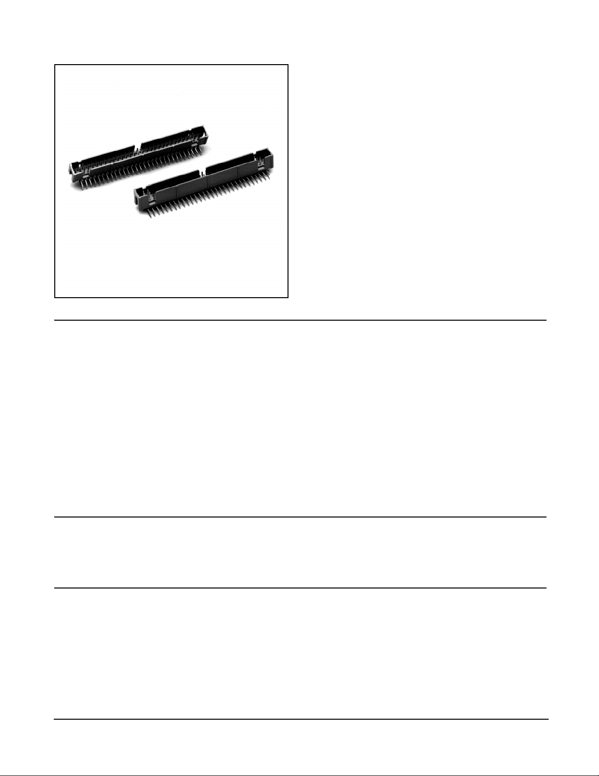
3M™ 4-Wall Header
.100″ × .100″ Low Profile, SMT Straight, PTH Straight and Right Angle 2500 Series
• Low profile, space saving design
• Center slot polarization prevents mis-insertions
and reduces insertion time
• Dual slot polarization means broader compatibility
with competitive polarization designs
• Optional retainer clip for locking sockets in place
and increasing connection reliability in vibrationprone environments
• High temperature insulator suitable for “no lead”
soldering operations
• Thru hole version suitable for "paste in hole" reflow
soldering techniques
• Exposed solder tails (on right angle version)
provide ease of cleaning and reduced repair costs
• RoHS* compliant
• Straight surface mount version available
Physical
Electrical
Insulator
Material:
Flammability:
Color:
Contact
Material:
Plating
Underplating:
Wiping Area:
Solder Tails:
Terminal Finish Indicator:
Marking:
Current Rating:
Insulation Resistance:
Withstanding Voltage:
Date Modified: June 21, 2006
Glass Filled Polyester (PCT)
UL 94V-0
Black
Copper Alloy
100 μ″ [ 2.54 μm ] Nickel - Overall
30 μ″ [ 0.76 μm ] Gold
200 μ″ [ 5.08 μm ] Matte Tin
e3 (per JESD97)
3M Logo, Part Identification Number and Orientation Triangle
2 A
>1 × 10⁹ Ω at 500 Vdc
1000 Vrms at Sea Level
TS-0770-17
Sheet 1 of 5
Environmental
Temperature Rating:
Process Rating:
Moisture Sensitivity Level:
"RoHS compliant" means that the product or part does not contain any of the following substances in exce ss of the following maximum con centration values
in any homogeneous material, unless the substance is in an application that is exempt under RoHS: (a) 0.1% (by weight) fo r l ead, mercury, hexavalent
chromium, polybrominated biphenyls or polybrominated diphenyl ethers; or (b) 0. 01% (by weigh t) for cadmium. Unless o the rwise sta ted by 3M in writ ing,
UL File No.: E68080
3M
Interconnect Solutions
http://www.3M.com/interconnects/
*RoHS = Directive 2002/95/EC, Restriction of the Use of Certain Hazardous Substances in Electrical and Electronic Equipment
-55°C to +105°C
Maximum 260°C, single pass, (profile per J-STD-020C)
1 (per J-STD-020C)
this information represents 3M's knowledge and belief based upon information provided by third party suppliers to 3M.
3M is a trademark of 3M Company.
For technical, sales or ordering information call
800-225-5373
Page 2
3M™ 4-Wall Header
.100″ × .100″ Low Profile, SMT Straight, PTH Straight and Right Angle 2500 Series
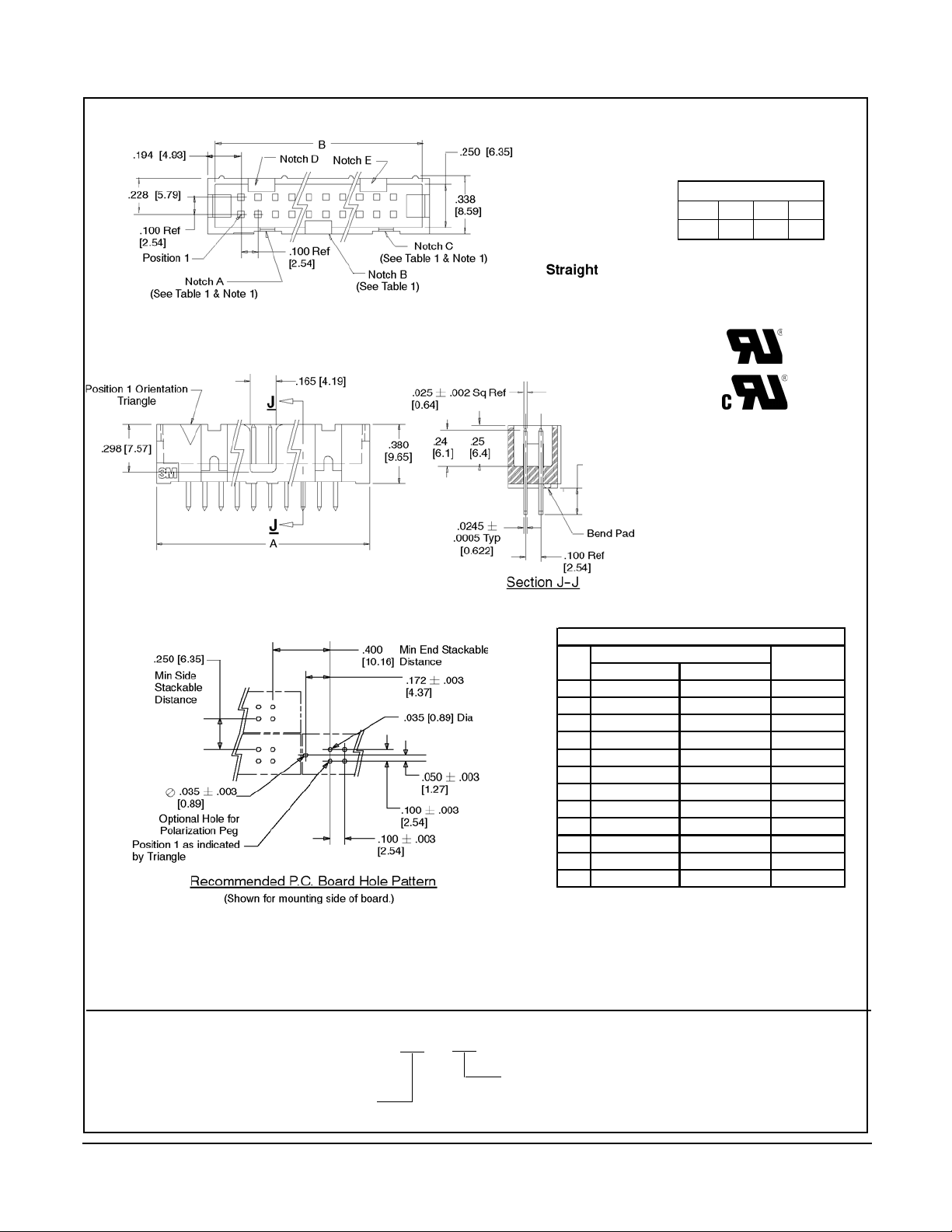
Inch
Tolerance Unless Noted
Inch
.112 +/- .01 [2.84] for 02 & K2 versions
.155 +/-.01 [3.94] for 03 version
[mm]
.00 .000
.0
± .01
± .1
[ ] Dimensions for
Reference only
± .005
Notes:
1. Notches A & C will accomodate 3M Polarizing Keys (3M Part #N3518).
2. Contact tails .0245 [0.622] crowned wire with .0075 [0.191] corner radii & .028 [.072] diagonal.
3. See page 4 for kink tail positions.
4. Solder stand offs facilitate .01 clearance above board for reflow soldering.
Ordering Information
N25XX-60XX-RB
Tail
02 = for .062 [1.57] thick board
Pin Quantity:
(See Table 1)
03 = for .094 to .125 [2.39 to 3.18] thick board
K2 = kinked for .062 [1.57] thick board
Table 1
Pin
Qty
Dimensions
AB
Polarizing
Notches
10 .788 [20.02] .708 [17.98] BC
14 .988 [25.10] .908 [22.06] B C D E
16 1.088 [27.64] 1.008 [25.60] A B C D E
20 1.288 [32.72] 1.208 [30.68] A B C D E
24 1.488 [37.80] 1.408 [35.76] A B C D E
26 1.588 [40.34] 1.508 [38.30] A B C D E
30 1.788 [45.42] 1.708 [43.38] A B C D E
34 1.988 [50.50] 1.908 [48.46] A B C D E
40 2.288 [58.12] 2.208 [56.08] A B C D E
50 2.788 [70.82] 2.708 [68.78] A B C D E
60 3.288 [83.52] 3.208 [81.48] A B C D E
64 3.488 [88.60] 3.408 [86.56] A B C D E
TS-0770-17
Sheet 2 of 5
3M
Interconnect Solutions
http://www.3M.com/interconnects/
3M is a trademark of 3M Company.
For technical, sales or ordering information call
800-225-5373
Page 3

3M™ 4-Wall Header
.100″ × .100″ Low Profile, SMT Straight, PTH Straight and Right Angle 2500 Series
Table 1
Pin
Qty
Dimensions
AB
10 .788 [20.02] .708 [17.98] BC
14 .988 [25.10] .908 [22.06] B C D E
16 1.088 [27.64] 1.008 [25.60] A B C D E
20 1.288 [32.72] 1.208 [30.68] A B C D E
24 1.488 [37.80] 1.408 [35.76] A B C D E
26 1.588 [40.34] 1.508 [38.30] A B C D E
30 1.788 [45.42] 1.708 [43.38] A B C D E
34 1.988 [50.50] 1.908 [48.46] A B C D E
40 2.288 [58.12] 2.208 [56.08] A B C D E
50 2.788 [70.82] 2.708 [68.78] A B C D E
60 3.288 [83.52] 3.208 [81.48] A B C D E
64 3.488 [88.60] 3.408 [86.56] A B C D E
Polarizing
Notches
.112 +/- .01 [2.84] for 02 & K2 versions
.155 +/-.01 [3.94] for 03 version
Notes:
1. Notches A & C will accomodate 3M Polarizing Keys (3M Part #N3518).
2. Contacts tails .0245 [0.622] crowned wire with .0075 [0.1 91] corner radii & .028 [.072] diag onal.
3. See page 4 for kink tail positions.
Ordering Information
N25XX-50XX-RB
Tail
02 = for .062 [1.57] thick board
Pin Quantity:
(See Table 1)
03 = for .094 to .125 [2.39 to 3.18] thick board
K2 = kinked for .062 [1.57] thick board
Inch
Tolerance Unless Noted
Inch
[mm]
.00 .000
.0
± .01
± .1
[ ] Dimensions for
Reference only
± .005
TS-0770-17
Sheet 3 of 5
3M
Interconnect Solutions
http://www.3M.com/interconnects/
3M is a trademark of 3M Company.
For technical, sales or ordering information call
800-225-5373
Page 4

3M™ 4-Wall Header
.100″ × .100″ Low Profile, SMT Straight, PTH Straight and Right Angle 2500 Series
B
.194
4.93
.228
5.79
.100
2.54
REF.
PIN 1
POSITION 1
ORIENTATION TRIANGLE
.380
9.65
.100
2.54
REF.
NOTCH D
.300
7.62
.200
5.08
NOTCH B
SEE TABLE 1
NOTCH A
SEE TABLE 1 & NOTE 1
NOTCH C
SEE TABLE 1 & NOTE 1
.165
4.19
A
A
A
NOTCH E
VACUUM CAP
.010
0.25
.298
7.57
.250
6.35
.338
8.59
.400
10.16
.0245
0.62
TYP
Tolerance Unless Noted
.0
Inch
± .1
[ ] Dimensions for
Reference only
VACUUM CAP
REMOVED FOR CLARITY
THIS VIEW
.25
6.43
.010
0.10
.005
0.10
.170
4.32
SECTION
Inch
[mm]
.00 .000
± .01
11.18
± .005
.243
6.17
.010.440
0.10
A-A
Table 1
Pin
Qty
10 .788 [20.02] .708 [17.98] BC WD (44 mm)
14 .988 [25.10] .908 [22.06] B C D E WD (44 mm)
16 1.088 [27.64] 1.008 [25.60] A B C D E WE (56 mm)
20 1.288 [32.72] 1.208 [30.68] A B C D E WE (56 mm)
24 1.488 [37.80] 1.408 [35.76] A B C D E WE (56 mm)
26 1.588 [40.34] 1.508 [38.30] A B C D E WF (72 mm)
30 1.788 [45.42] 1.708 [43.38] A B C D E WF (72 mm)
34 1.988 [50.50] 1.908 [48.46] A B C D E WF (72 mm)
40 2.288 [58.12] 2.208 [56.08] A B C D E WH (120 mm)
50 2.788 [70.82] 2.708 [68.78] A B C D E WG (88 mm)
60 3.288 [83.52] 3.208 [81.48] A B C D E WH (120 mm)
64 3.488 [88.60] 3.408 [86.56] A B C D E WH (120 mm)
Notes:
1. Notches A & C will accommodate 3M polarizing key N3518.
2. Vacuum cap will be centered on connectors with odd # ofpins/row. It will be offset away from Pin 1 on connectors having an even # of pins per row (shown).
3. Coplanarity .004 for less than 30 position, .006 for 30 and above.
Dimensions
AB
Ordering Information
3M
Interconnect Solutions
http://www.3M.com/interconnects/
Polarizing
Notches
Pin Quantity:
(See Table)
Tape & Reel
Pkg Code
N25XX-6V0C-RB -XX
Packaging Options:
WX = tape & reel packaging (see table)
3M is a trademark of 3M Company.
For technical, sales or ordering information call
TS-0770-17
Sheet 4 of 5
800-225-5373
Page 5

3M™ 4-Wall Header
.100″ × .100″ Low Profile, SMT Straight, PTH Straight & Right Angle 2500 Series
2500 & 3000 Serie s Shroude d He ade r
Total
Number of
Pins
10 4 3 4 7 8
14 4 3 4 11 12
16 4 3 4 13 14
20 4 3 4 17 18
24 4 3 4 21 22
26 4 3 4 23 24
30 4 5 6 25 26
34 4 7 8 27 28
36 4 7 8 27 28
40 4 7 8 33 34
50 4 7 8 43 44
60 4 11 12 49 50
64 4 11 12 53 54
Kinked Tail Detail:
Kink is located .05” below bottom surface of plastic.
External radius of kink toward part centerline.
Number of
Tails Kinked
Positions Kinked
Part Number Material Color
3505-33B Nylon Black
.144
[3.66]
.204
[5.18]
Connector
Dimension
Pin Qty
10 .81 [20.6,]
14 1.02 [25.9]
16 1.12 [28.4]
20 1.32 [33.5]
24 1.52 [38.7]
26 1.63 [41.4]
30 1.83 [46.4]
34 2.03 [51.6]
40 2.33 [59.2]
50 2.83 [71.9]
60 3.33 [84.6]
64 3.53 [89.7]
Maximum Uncoated Area
A
Clip Height Code
0 = .31 [ 7.9 ] for Sockets W/O
Strain Relief
1 = .53 [ 13.5 ] for Sockets with
Strain Relief
A
(On both edges)
3505-8XXX
Connector Pin Count:
(See Table)
.11
[2.8]
.830
[21.08]
.057
[1.45]
.573
[14.55]
.118
[3.00]
.043
[1.09]
Long Snap In Latch
Note: Latches not compatible with reflow soldering. For reflow soldering,
attach latches after soldering.
Part Number Material Color
3201-3 PCT Black
.118
[3.00]
.370
[9.40]
.030 Dia
[0.76]
.267
[6.78]
Polarizing Post
.082
[2.10]
.102
[2.59]
.2 ± .1
[5.1]
Alternate
Uncoated
Area
Clip Height
Code
Short/Long Socket Retainer Clip
Note: Stainless steel with gray polyurethane coating.
Part Number Material Color Dim A
N3518 LCP Black 0.02
Breakaway Tab
.15
[3.8]
Note: #2216 B/A Scotchweld can be used to adhere keys.
.34 Ref
[8.6]
Polarizing Keys
.09
[2.3]
A
TS-0770-17
Sheet 5 of 5
3M
Interconnect Solutions
http://www.3M.com/interconnects/
3M is a trademark of 3M Company.
For technical, sales or ordering information call
800-225-5373
Page 6

Important Notice
All statements, technical information, and recommendations
related to 3M’s products are based on information believed to be
reliable, but the accuracy or completeness is not guaranteed.
Before using this product, you must evaluate it and determine if it
is suitable for your intended application. You assume all risks and
liability associated with such use. Any statements related to the
product which are not contained in 3M’s current publications, or
any contrary statements contained on your purchase order shall
have no force or effect unless expressly agreed upon, in writing,
by an authorized officer of 3M.
3
3M Electronics
6801 River Place Blvd.
Austin, TX 78726-9000
800/225-5373
www.3M.com/electronics
Warranty; Limited Remedy; Limited Liability.
This product will be free from defects in material and manufacture
for a period of 90 days from the time of purchase. 3M MAKES
NO OTHER WARRANTIES INCLUDING, BUT NOT LIMITED
TO, ANY IMPLIED WARRANTY OF MERCHANTABILITY OR
FITNESS FOR A PARTICULAR PURPOSE. If this product is
defective within the warranty period stated above, your exclusive
remedy shall be, at 3M’s option, to replace or repair the 3M
product or refund the purchase price of the 3M product.
where prohibited by law, 3M will not be liable for any indirect,
special, incidental or consequential loss or damage arising
from this 3M product, regardless of the legal theory asserted.
Minimum 10%
Post-Consumer Fiber
Printed in USA.
© 3M 2006
Except
 Loading...